Embed Size (px)
Citation preview
US 20030054962A1
(12) Patent Application Publication (10) Pub. No.: US 2003/0054962 A1 (19) United States
England et al. (43) Pub. Date: Mar. 20, 2003
(54) METHODS FOR STIMULATING HYDROCARBON PRODUCTION
(76) Inventors: Kevin W. England, Houston, TX (US); Curtis L. Boney, Houston, TX (US); Matthew J. Miller, Missouri City, TX (Us)
Correspondence Address: SCHLUMBERGER TECHNOLOGY CORPORATION IP DEPT., WELL STIMULATION 110 SCHLUMBERGER DRIVE, MDl SUGAR LAND, TX 77478 (US)
(21) Appl. No.: 10/195,704
(22) Filed: Jul. 15, 2002
Related U.S. Application Data
(60) Provisional application No. 60/312,340, ?led on Aug. 14, 2001.
Publication Classi?cation
(51) Int. Cl? ..................................................... ..C09K 7/00 (52) U.S. c1. ............................................................ .. 507/117
(57) ABSTRACT Methods are provided for stimulation of hydrocarbon pro duction from loW permeability formations by hydraulic fracturing, acid fracturing, and hydraulic fracturing folloWed by gravel packing in a single operation. The methods use a ?rst injected viscous pad made With loW concentration uncrosslinked polymer to initiate and propagate the fracture and control ?uid loss, folloWed by a second injected ?uid gelled With a viscoelastic surfactant for carrying proppant or acid into the fracture.
Patent Application Publication Mar. 20, 2003 Sheet 1 0f 2 US 2003/0054962 A1
CONDUCTIVITY IN MD-FT O
‘6:’ O I m
855 ‘"2 "'< Zn: :4
-25: ‘°zn:~ Lu:
"'6 LL. _|<
QSEE 'gmo
cc< :nr:
5“. 355 l -8“-<
N E ,_
9 U
C
Patent Application Publication Mar. 20, 2003 Sheet 2 0f 2 US 2003/0054962 A1
ooo _. oow
CONDUCTIVITY lN MD-FT
IA _
oo o
oow
ooN
m o o
SEHONI NI H.l.CllM CIHddOHd

US 2003/0054962 A1
METHODS FOR STIMULATING HYDROCARBON PRODUCTION
REFERENCE TO RELATED PROVISIONAL APPLICATION
[0001] This application claims the bene?t of provisional application serial No. 60/312,340 ?led Aug. 14, 2001.
TECHNICAL FIELD OF THE INVENTION
[0002] This Invention relates to stimulation of Wells drilled into subterranean formations to improve recovery of hydrocarbons. In particular it relates to hydraulic fracturing and acid fracturing of loW permeability producing Zones to improve the ?oWpath available to oil and gas ?oWing to the Wellbore. Most particularly it relates to using less expensive chemicals, less complicated procedures, and less hydraulic horsepoWer to create fractures that have greater Width and higher conductivity than Would be produced by other meth ods When fracturing comparable formations.
BACKGROUND OF THE INVENTION
[0003] Stimulating the production of hydrocarbons (or other ?uids such as Water, brine, and carbon dioxide) is Well knoWn. Hydraulic fracturing (pumping a ?uid into a Well bore at a pressure and rate suf?cient to split open the formation rock), acidiZing, or a combination of the tWo (called acid fracturing or fracture acidiZing) are the most common techniques. In hydraulic and acid fracturing, a ?rst, viscous ?uid called a “pad” is typically injected into the formation to initiate and propagate the fracture and often to contribute to ?uid loss control. This is folloWed by a second ?uid. In hydraulic fracturing the second ?uid contains a proppant that keeps the fracture open after the pumping pressure is released. In acid fracturing, the second ?uid contains an acid that can dissolve part of the rock, causing irregular etching of the fracture face and removal of some of the mineral matter, resulting in the fracture not completely closing When the pumping is stopped. The choice of the pad ?uid depends upon the nature of the subsequently injected ?uid and of the formation and on the desired results and attributes of the stimulation job.
[0004] Occasionally, hydraulic fracturing is done Without a highly viscosi?ed second ?uid; this choice is made pri marily as a Way to reduce the deleterious effect of polymers described beloW. This technique, sometimes called a “Water frac” involves using extremely loW polymer concentrations, so loW that they cannot be effectively crosslinked, through out the job. This alternative has a major draWback: since there is inadequate viscosity to carry much proppant, high pump rates must be used and only very small concentrations (pounds mass proppant added per gallon of ?uid), called “PPA”, of proppant can be used. Very little proppant Will be placed in the fracture to keep it open after the pumping is stopped. [0005] Pads and fracturing ?uids are usually viscosi?ed in one of three Ways. If the injected ?uid is an oil, it is gelled With certain additives designed for the purpose, such as certain aluminum phosphate compounds. If the ?uid is Water or brine, for hydraulic or acid fracturing, it is gelled With polymers (usually crosslinked With a boron, Zirconium or titanium compound), or With viscoelastic ?uids (“VES’s”) that can be formed using certain surfactants that form
Mar. 20, 2003
appropriately siZed and shaped micelles. Polymers, espe cially crosslinked polymers, often tend to form a “?ltercake” on the fracture face, that is they coat out on the fracture face as some ?uid leaks off, provided that the rock pores are too small to permit entry of the polymer or crosslinked polymer. Some ?ltercake is generally desirable for ?uid loss control. This process of ?ltercake formation is also called Wallbuild ing. VES ?uids do not form ?ltercakes as a result of leak-off. VES leak-off control is viscosity controlled, i.e., the resis tance due to the ?oW of the viscous VES ?uid through the formation porosity limits the leak-off rate. The viscosity controlled leak-off rate can be high in certain formation permeabilities because the highly shear-thinning ?uid has a loW apparent viscosity in high ?oW velocity areas. Reducing the ?oW velocity (by correspondingly reducing the pressure gradient or simply as a result of the same injected volumetric ?oW rate leaking off into the formation through a greater surface area as the fracture groWs in length and height) Will alloW micelle structure to reassemble and Will result in regeneration of viscosity and ?uid loss control. On the other hand, polymers have tWo major de?ciencies: a) the ?lter cake, if left in place, can impede subsequent ?oW of hydro carbons into the fracture and then into the Wellbore, and b) polymer or crosslinked polymer Will be left in the fracture itself, impeding or cutting off ?oW, either by physically blocking the ?oW path through the proppant pack or by leaving a high viscosity ?uid in the fracture. VES ?uids do not form a ?ltercake or leave solids in the fracture. VES ?uids therefore leave a cleaner, more conductive and there fore more productive fracture. They are easier to use because they require feWer components and less surface equipment, but they may be more expensive and less ef?cient than polymers, depending upon the formation permeability and the speci?c VES system and polymer system.
[0006] For expediency, pads are typically chemically simi lar to the fracture ?uids used in the same job. Thus in hydraulic fracturing With Water-based crosslinked polymer containing ?uids, the pad is typically a Water-based crosslinked or uncrosslinked polymer. Crosslinking decreases the amount of polymer needed but increases complexity and often the cost of the job and usually leaves a more harmful residue on the fracture face or in the fracture after the job. In hydraulic fracturing With Water-based VES ?uids, the pad is typically also a Water-based VES ?uid, but all of this ?uid leaks off, and it may be expensive.
[0007] US. Pat. No. 5,036,919 (Ronnie L. Thomas and Curtis L. Boney, issued Aug. 6, 1991), hereby incorporated by reference, describes the bene?t and importance of a method of fracturing designed to minimiZe damage to the fracture proppant pack conductivity by using a less damag ing, less thermally stable, viscosi?er in the fracture ?uid than in the pad. In that case, the pad Was an organo-metallic crosslinked polymer-based system and the fracture ?uid Was preferably a borate-crosslinked polymer-based system.
[0008] Whereas, the pad is typically the same chemical system (albeit at different concentrations as the proppant laden or acid containing stages), optimal performance may be realiZed by using substantially different ?uid chemistry or ?uid types for both the pad and proppant-laden or acid containing stages. The pad need not be chemically the same as the ?uid used in the later stages since the pad does not need to transport proppant or acid and the stimulation plan may include greater pad leak-off than leak-off of subsequent

US 2003/0054962 A1
fracture stages. There is a need in hydraulic and acid fracturing to provide an inexpensive material for the pad that Will a) create and propagate a su?iciently Wide fracture, b) minimize chemical, equipment and hydraulic horsepower expense, c) form a ?ltercake to control leak-off during the job (not absolutely needed in all cases, for example not required When acid fracturing With a loW viscosity acid) and d) be degradable to maximiZe subsequent production.
SUMMARY OF THE INVENTION
[0009] In loW permeability formations being fractured With VES ?uids, a loW concentration (such as about 10 to about 15 ppt (pounds per thousand gallons ?uid)) of uncrosslinked polymer may be used in the pad and provide an inexpensive and effective material for the pad that Will a) create and propagate a su?iciently Wide fracture, b) mini miZe complexity and chemicals, equipment and hydraulic horsepoWer requirements, c) form a ?ltercake to control leak off during the job (not absolutely needed in all cases, for example not required When acid fracturing With a loW viscosity acid) and d) be degradable to maximiZe subsequent production. This optimiZes the pad and the fracture ?uid separately for loW permeability formations. The viscosity of the uncrosslinked polymer may actually be loWer than that of the VES ?uid subsequently pumped, but the uncrosslinked polymer is less expensive than crosslinked polymer or than VES, less complicated to use and requires feWer chemicals and less equipment than crosslinked poly mer, and, in loW permeability formations, Will still form a ?ltercake to increase fracture generation e?iciency. Either the pad or the subsequent fracture ?uid or both can be foamed or energiZed, if the surfactants selected to form the VES are knoWn to create stable foams, or if the ?uids further comprise foamers and the VES surfactants selected are not anti-foamers. The pad and subsequently pumped fracture ?uid may have all the additives typically used in such ?uids. The job may be a hydraulic fracture, an acid fracture or a fracture immediately folloWed by gravel-packing, for example With a screen in place, in a single operation. It is a particularly important aspect of the Invention to employ these ?uids and methods in fracturing jobs in Which only a small amount of proppant is used (commonly called “Water fracs” or “Water-fracs” or “slickWater fracs”. It is another particularly important aspect of the Invention that the meth ods alloW pads ahead of VES fracture ?uids to be pumped With minimiZed hydraulic horsepoWer, number of pumps, etc. relative to conventional fracturing With pad composi tions previously knoWn in the art for VES based ?uids. It is another aspect of the Invention to generate a higher con ductivity fracture than if crosslinked polymer or a high concentration of uncrosslinked polymer Was used in the pad. It is yet another aspect of the present Invention to provide sufficient fracture Width and ?uid loss control While mini miZing damage to the proppant pack When proppant is used. A particularly preferred embodiment of the Invention is a method of stimulating production of ?uids from subterra nean formations penetrated by a Wellbore involving inject ing a ?rst ?uid (the pad), made from an aqueous carrier ?uid containing an uncrosslinked polymer at a concentration of less than about 15 pounds per thousand gallons ?uid, and then injecting a second ?uid containing a thickening amount of a viscoelastic surfactant. The key unifying element of the methods of the Invention is a loW concentration of an inexpensive, easy to use uncrosslinked polymer used in the
Mar. 20, 2003
pad to minimiZe damage due to the pad While then subse quently using a fracturing ?uid that is completely non damaging but nonetheless has excellent proppant carrying properties.
BRIEF DESCRIPTION OF THE FIGURES
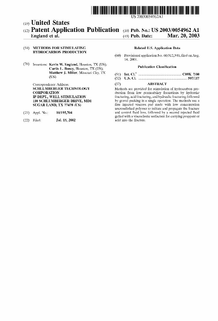
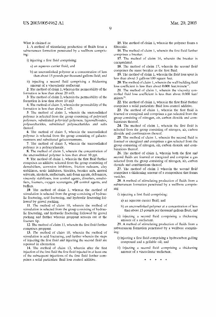
[0010] FIG. 1 shoWs results predicted When fracturing With loW proppant concentrations and only Water and a friction reducer in the pad and the proppant stages.
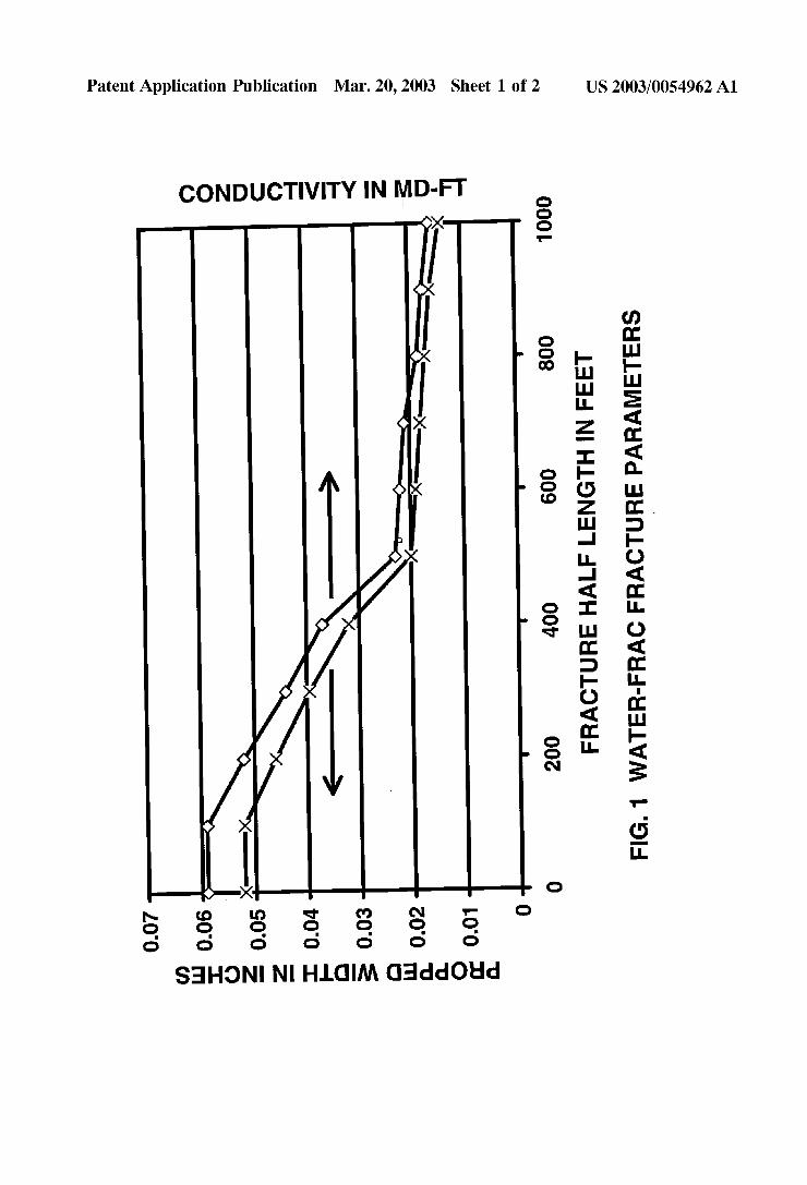
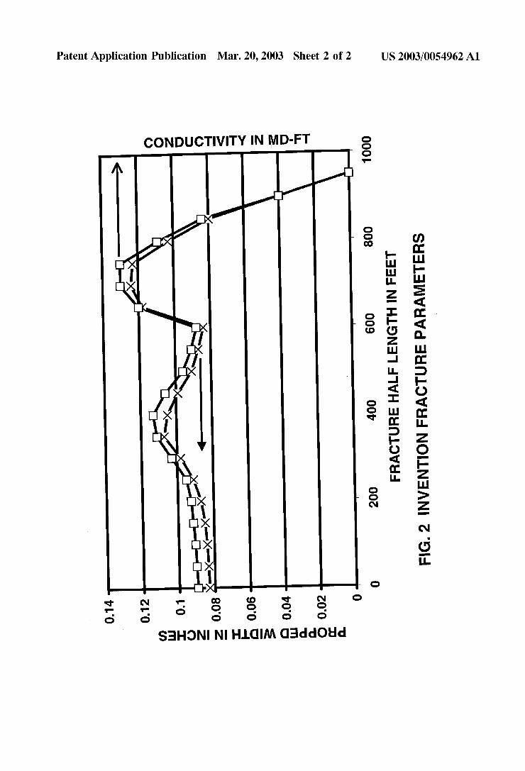
[0011] FIG. 2 shoWs results predicted When fracturing With loW proppant concentrations, the uncrosslinked loW polymer concentration pad of the Invention, and a VES ?uid in the proppant stages.
DESCRIPTION OF ILLUSTRATIVE EMBODIMENTS
[0012] In hydraulic fracturing according to this Invention, most of the injected fracturing ?uid contains a proppant such as sand or synthetic ceramic beads, so that When the pressure is released the proppant is trapped betWeen the fracture faces and prevents the fracture from completely closing, thus leaving a ?oWpath open. The injected fracturing ?uid is viscosi?ed. Increased viscosity results in formation of a Wider fracture, thus a larger ?oWpath. A minimal viscosity is also required to transport adequate amounts of proppant; the actual viscosity required depends primarily upon the ?uid ?oW rate and the density of the proppant. In a typical fracturing process, such as hydraulic fracturing With aque ous ?uids, the fracture is initiated by ?rst pumping a high viscosity crosslinked polymer-based aqueous ?uid With good to moderate leak-off properties, relatively loW polymer loadings, and typically no proppant, into the formation. This initial ?uid, typically referred to as a “pad”, is usually folloWed by a second ?uid (fracturing ?uid) of similar viscosity carrying an initially loW concentration and then a gradually increasing concentration of proppant into the extended fractures. The pad initiates and propagates the fracture but does not need to carry proppant. All the ?uids tend to “leak-off” into the formation from the fracture being created. Commonly, by the end of the job the entire volume of the pad Will have leaked off into the formation. This leak-off is determined and controlled by the properties of the ?uid (and additives it may contain) and the properties of the rock. A certain amount of leak-off greater than the minimal possible may be desirable, for example a) if the intention is to place some ?uid in the rock to change the rock properties or to ?oW back into the fracture during closure, or b) if the intention is deliberately to cause What is called a “tip screen-out”, or “TSO”, a condition in Which the proppant forms a bridge at the end of the fracture, stopping the lengthening of the fracture and resulting in a subsequent increase in the fracture Width. On the other hand, excessive leak-off is undesirable because it may Waste valuable ?uid and result in reduced e?iciency of the job. Proper leak-off control is therefore critical to job success. Many solid particulate additives, such as silica, mica and starch, have been developed to control leak-off.
[0013] In acid fracturing methods of the Invention, the injected ?uid contains an acid that dissolves a portion of the rock by a process like etching so that, When the pumping is stopped and the pressure is released and the fracture closes, the fracture faces no longer match up and an open path to the

US 2003/0054962 A1
Wellbore is left in place. This serves the function of the proppant in conventional hydraulic fracturing. The acid may also create Wormholes into the rock to form additional pathWays, Which is usually undesirable in acid fracturing because it Wastes acid and draWs the acid in undesirable directions. Acids are often viscosi?ed to increase fracture Width and to reduce the rate of acid leak-off into the fracture face. Acid fracture jobs are also typically preceded With pads, typically crosslinked polymers, or extremely high concentration uncrosslinked polymers, as in hydraulic frac turing.
[0014] Fracture ?uids described herein typically also con tain other materials such as demulsi?ers, corrosion inhibi tors, friction reducers, clay stabiliZers, scale inhibitors, bio cides, breaker aids, mutual solvents, alcohols, surfactants, anti-foam agents, defoamers, viscosity stabiliZers, iron con trol agents, diverters, emulsi?ers, foamers, oXygen scaven gers, pH control agents, and buffers, and the like. The fracture jobs of the Invention are conducted normally eXcept for the composition, and sometimes amount, of the pad. The pad and the fracturing or other stimulation ?uid and their additives are transported to the site, miXed, stored, and pumped in the usual Ways for the respective chemicals. In the term “fracture” We include hydraulic fracturing, acid fracturing and combined fracturing folloWed by gravel pack ing in a single operation.
[0015] The Invention is carried out by considering infor mation about the Well, the formation, the ?uids available, and criteria for a successful fracture stimulation, and pre paring an optimiZed plan for maXimiZing stimulated Well performance according to the data and the criteria. Such a design Will include injection of an amount of a selected pad ?uid and an amount of a selected fracture ?uid. This is usually done by analyZing the Well using fracturing design and evaluation softWare in Which pressure gradients are combined With fracture length and height evolution algo rithms, complete leak-off information, and the effects of multiple ?uid injections and their temperature changes. Given loW concentration uncrosslinked polymer ?uids as options for the pad and VES ?uids as options for the fracturing or other stimulation ?uid, this job design is Well Within the capability of those skilled in the art.
[0016] The theory and practice of hydraulic fracturing, acid fracturing, and fracturing With deliberate tip screen-out are given in detail in Michael J. Economides and Kenneth G, Nolte, eds., Reservoir Stimulation, John Wiley and Sons, Ltd, 3rd Edition, NeW York, 2000, in particular Chapter 5, “Basics of Hydraulic Fracturing” by M. B. Smith and J. W. Shlyapobersky (pp.5-1 to 5-28); Chapter 7, “Fracturing Fluid Chemistry and Proppants” by Janet Gulbis and Rich ard M. Hodge (pp. 7-1 to 7-23); and Chapter 10, “Fracture Treatment Design” by Jack Elbel and Larry Britt (pp. 10-1 to 10-50).
[0017] We de?ne loW permeability formations here as having permeabilities of less than about 20 mD, especially less than about 10 mD, and most especially less than about 2 mD. One important issue With polymer-free ?uid systems, in loW permeability formations, if they are used for both the pad and the proppant carrying fracture ?uid, is that there are no solids to aid in controlling ?uid loss to the formation during fracturing. In these cases it Would be desirable to pump a polymer-based ?uid for the pad folloWed by a
Mar. 20, 2003
VES-based (or other solids-free) ?uid to carry proppant or to divert or delay an acid. This might cause some fracture face damage as a result of the solids in the pad, Which can be addressed by chemical (usually encapsulated) breakers, Which in some cases are chemically equivalent to the chemistry needed to promote faster cleanup of the VES based ?uids.
[0018] The pad of the Invention comprises a carrier ?uid and a viscosifying polymer. It may additionally contain other additives normally used in such ?uids, provided that none of the components of the pad is deleterious to the formation or to the fracture ?uid. Fluids used as the pad in the present Invention may typically contain materials such as corrosion inhibitors, friction reducers, clay stabiliZers, scale inhibitors, biocides, and the like.
[0019] The carrier ?uid provides a medium for the trans port of the other components into the formation. Preferably, the carrier ?uid can be Water or brine. Selected organic or inorganic salts or miXtures can be used, provided that they are compatible With all components in the pad, the fracture ?uid, the formation and the formation ?uids. Solutions containing 1 to 5% by Weight potassium chloride (KCl) or ammonium chloride are often used as the base liquid in fracturing ?uids and pads to stabiliZe clays and prevent sWelling. Sometimes other brines or sea Water may be used. An organic cation salt, such as, in particular, tetramethyl ammonium chloride, is an effective salt at about 0.2 to about 0.5 percent by Weight.
[0020] Typically, the polymer is Water-soluble. Common classes of effective Water-soluble polymers include polyvi nyl polymers, polymethacrylamides, cellulose ethers, polysaccharides, lignosulfonates, and ammonium, alkali metal, and alkaline earth salts thereof. Speci?c eXamples of typical Water soluble polymers are acrylic acid-acrylamide copolymers, acrylic acid-methacrylamide copolymers, poly acrylamides, partially hydrolyZed polyacrylamides, partially hydrolyZed polymethacrylamides, polyvinyl alcohol, poly vinly acetate, polyalkyleneoXides, carboXycelluloses, car boXyalkylhydroXyethyl celluloses, hydroXyethylcellulose, galactomannans (e.g., guar gum), substituted galactoman nans (e.g., hydroXypropyl guar, carboXymethyl hydroXypro pyl guar, and carboXymethyl guar), heteropolysaccharides obtained by the fermentation of starch-derived sugar (e.g., Xanthan gum), and ammonium and alkali metal salts thereof. Preferred Water-soluble polymers include hydroXyethyl cel lulose, starch, scleroglucan, galactomannans, and substi tuted galactomannans.
[0021] The uncrosslinked polymer pad is used at a con centration of up to about 10 ppt if the pad ?uid is foamed or energiZed and up to about 15 ppt if the pad ?uid is not foamed. This concentration is loWer than that used in pads in fracturing procedures in the past, in Which the minimal polymer concentration Was about 15 ppt if the polymer Was crosslinked or foamed and about 20 ppt if the polymer Was uncrosslinked. US. Pat. No. 5,036,919 (Ronnie L. Thomas and Curtis L. Boney, issued Aug. 6, 1991), hereby incorpo rated by reference, describes hydraulic fracturing With crosslinked guar-based polymer ?uids, Which may be foamed, and states that the polymer loading in the pad may be from about 20 to about 80 ppt (pounds per thousand gallons ?uid). The minimal polymer concentration depends upon the dimensions of the pore system of the formation, the

US 2003/0054962 A1
pump rate, the desired fracture dimensions, and the choice of polymer and its properties as they affect Wallbuilding and the ability of the polymer to viscosify the pad ?uid. The minimal polymer concentration is about 2 ppt for synthetic polymers such as polyacrylamide and about 10 ppt for natural poly mers such as guars and substituted guars. These minima are
the same Whether the pad ?uid is foamed or not. The optimal polymer concentration can be determined by choosing the desired leak-off parameters and measuring leak-off With samples of the intended ?uids and of the formation or of a rock similar to the formation. Leak-off is de?ned by three terms: “spurt”, Which is the initial rapid leak-off of ?uid before a ?ltercake barrier is formed on the fracture face and is measured in gallons/100 square feet, and, for the subse quent leak-off that occurs even after a ?ltercake is formed and is governed by the viscosity and the Wall-building propensity: CW, the Wall-building ?uid loss coefficient, and Cv, the viscosity controlled ?uid loss coef?cient. CW is not applicable Where there is no Wall-building material present. Cv is not applicable Where there is a loW, ?nite CW. CW and Cv are measured in ft/min1/2. Preferred values of spurt, CW and Cv respectively are 0 to about 5, about 0.001 to about 0.05, and about 0.001 to about 0.05; more preferred values are 0 to about 2, about 0.001 to about 0.008, and about 0.001 to about 0.008; most preferred values are 0 to about 1, about 0.001 to about 0.003, and about 0.001 to about 0.003. Atest method for determining these values is given in Navarrete, R. C., CaWeiZel, K. E., and Constien, V. G.: “Dynamic Fluid Loss in Hydraulic Fracturing Under Realistic Shear Condi tions in High-Permeability Rocks,” SPE Production and Facilities, pp 138-143 (August, 1996).
[0022] The pad may be foamed or energiZed With a gas such as air, nitrogen, carbon dioxide or mixtures thereof to provide some energy and to decrease the amount of chemi cals needed. In this embodiment, any surfactant capable of alloWing suf?cient foaming of the ?uid (i.e. at least about 50%, preferably about 70%, gas by volume at one atmo sphere pressure and about 20-40° C.) can be used in the ?uid. The selection of a suitable surface active agent or agents to form the foam is Within the ability of those skilled in the art. Preferred surfactants are those that are effective When incorporated into Water in a concentration of about 5 volume percent or less and are compatible With all compo nents in the pad, the fracture ?uid, the formation and the formation ?uids.
[0023] In a typical propped hydraulic fracturing treatment, the pad ?uid is designed to completely leak off into the formation; this complete leak-off ideally coincides precisely With the termination of pumping of the proppant stages (pumping a slurry containing proppant) so that the neWly created fracture is propped open. Thus the volume of the pad, relative to the volume of the fracture ?uid, is deter mined by a large number of factors governed by the prop erties of the ?uids and of the formation and the desired ?nal fracture dimensions. The selection of a suitable pad volume is Within the ability of those skilled in the art, taking into account the affects of the loWer polymer concentration of the Invention on pad viscosity and ?uid loss.
[0024] Because the polymer in the pad is pumped only ahead of the polymer-free fracture ?uid containing the proppant, the proppant bed left in the fracture after the job
Mar. 20, 2003
does not contain signi?cant and deleterious amounts of solids, as Would be the case if the fracture ?uid contained any polymer.
[0025] The methods of the present Invention Work satis factorily in formations in Which the pore throats at the fracture faces are suf?ciently small that the uncrosslinked polymer molecules in the pad cannot enter the formation, but rather form a ?ltercake on the fracture faces (except in some cases, for example acid fracturing With a loW viscosity ungelled ?uid). The most common Way to determine Whether this criterion is met is through measurement or estimation of the formation permeability. The preferred formation permeability for the present Invention is less than about 20 mD; more preferred is less than about 10 mD; most preferred is less than about 2 mD. If this criterion is not met, then a pad having a composition knoWn in the art, such as a crosslinked polymer, a high concentration of an uncrosslinked polymer or a VES ?uid, must be used. In loW permeability formations, only minimal ?uid loss control is generally needed, and provision of viscosity to Widen the fracture is a relatively more important role of the pad ?uid. In high permeability formations, ?uid loss control is more dif?cult and more critical and uncrosslinked polymer per meates the formations.
[0026] While this Invention is not bound by any particular mechanism of operation or theory, it appears that one can de?ne three permeability ranges for a given polymer, crosslinked polymer, or VES ?uid:
[0027] First, a high permeability range, above Which the polymer, crosslinked polymer, or VES ?uid micelles can enter the formation Without forming a ?ltercake such that leak-off is high in the absence of added leak-off control agents such as mica or starch.
[0028] Second, an intermediate permeability range, depending upon the dimensions of the polymer, crosslinked polymer, or VES ?uid micelles, and the stability of the micelles of the VES ?uid, the crosslinked polymer could not enter, the uncrosslinked polymer could enter, and the micelles either could enter or could break, then enter as surfactant molecules, and then reform.
[0029] Third, a loWer permeability beloW Which, still depending upon the dimensions of the polymer, crosslinked polymer, and VES ?uid micelles, and the stability of the micelles of the VES ?uid, the crosslinked polymer could not enter, the micelles either could enter or could break and enter as surfactant micelles and then reform or not reform, and the uncrosslinked polymer could not enter. (Polymer or crosslinked polymer that does not enter forms a ?ltercake.)
[0030] One skilled in the art and knoWing the properties of the formation and the properties of the ?uid components could determine When a VES ?uid might extensively enter (leak-off into) a formation but an uncrosslinked polymer Would not. This Would depend, for example, upon the nature of the VES, the structure and molecular Weight of the polymer, and the formation permeability and pore structure. In that case, the methods of this Invention Would be most valuable. US. Pat. No. 5,964,295 (BroWn, et. al., issued Oct. 12, 1999; hereby incorporated by reference) describes sev eral types of effective VES ?uids, although the Invention is not limited to those VES ?uids, and explains the inter relationships of viscosity, and ?uid loss and leak-off in
US 2003/0054962 A1
relatively loW permeability formations (less than about 10 mD for the VES ?uid surfactants described in Us. Pat. No. 5,964,295, but different for different VES ?uid surfactants).
[0031] In most, if not all, fracture treatments, leak-off in excess of the minimal amount required for optimal ?uid ef?ciency and fracture dimensions is inevitable and unde sirable. Moderate leak-off of the pad in the present Inven tion, in excess of this minimum, can be acceptable because the pad ?uid is less expensive than pad ?uids used previ ously in the art, is less complicated and easier to use than most, and in particular is less expensive than the subse quently injected, proppant-carrying VES fracture ?uid.
[0032] Reduction of the deleterious effects of polymers left in the fracture is usually brought about by “breakers” that are intended literally to destroy the polymer. These are usually oxidiZers or enZymes. VES ?uid micelles are usually broken by the natural in?oW of hydrocarbons and Water or brine, but breakers such as certain salts or alcohols are sometimes also used. Breaker aids such as activators, delay agents or stabiliZers may also be used speci?cally in con junction With the breakers.
[0033] Examples of breakers suitable for use in the method of the present Invention include enZymes such as galactomannanase (for breaking polysaccharides based on galactomannan) and oxidiZers such as ammonium persulfate (for breaking all polymers by oxidation and for breaking some of the VES micelles by increasing the salinity). Additionally, the breakers can be encapsulated to delay their release, as is Well knoWn in the art. Encapsulation is advan tageous because most or all of the polymer to be broken Will be in the ?ltercake and, With encapsulation, that is Where the breaker Will be after the job. If the breaker is not encapsu lated, at least some of it Will leak off and not be in contact With the polymer in the ?ltercake, although some may ?oW back into contact With the polymer When the fracture pres sure is released. Encapsulation is also advantageous because a breaker can be chosen that Will break both the polymer and the micelles in the VES. Encapsulation is also advantageous for the delayed reaction it provides.
[0034] Any VES based ?uid can be used, after the pad, that is compatible With the formation, the formation ?uids, and the pad ?uid and its components and additives. Particu larly effective non-limiting examples of ?uids are those described in Us. Pat. Nos. 5,551,516; 5,964,295; 5,979, 555; 5,979,557; 6,140,277; and 6,258,859, all hereby incor porated by reference.
[0035] Although the Invention has been described throughout using the term “VES”, or “viscoelastic surfac tant” to describe the non-polymeric viscosi?ed aqueous ?uid in the second stage, any non-polymeric material may be used to viscosify the aqueous ?uid provided that the requirements described herein for such a ?uid are met, for example the required viscosity, stability, compatibility, and lack of dam age to the Wellbore, formation or fracture face. Examples, Without regard to Whether they form, or are described as forming, vesicles or viscoelastic ?uids, include, but are not limited to, those viscosi?ers described in US. Pat. No. 6,035,936 and in GB application No. 2,366,307A.
[0036] The proppant may be any synthetic or natural proppant used in hydraulic fracturing, including but not limited to glass beads, ceramic beads, sand, and bauxite. The
Mar. 20, 2003
proppant may be resin coated, provided that the resin and any other chemicals in the coating are compatible With the other chemicals of the Invention, particularly the compo nents of the viscoelastic surfactant ?uid micelles.
[0037] Also optionally, the fracturing ?uid can contain materials designed to limit proppant ?oWback after the fracturing operation is complete by forming a porous pack in the fracture Zone. Such materials can be any knoWn in the art, such as are available from Schlumberger under the tradename PropNETTM (for example see US. Pat. No. 5,501,275). Exemplary proppant ?oWback inhibitors include ?bers or platelets of novoloid or novoloid-type polymers (US. Pat. No. 5,782,300).
[0038] This Invention may be practiced at any formation temperature, taking into account any cool-doWn that may occur, at Which the pad and fracture ?uids and their com ponents, in particular the polymer in the pad and the VES and micelles in the fracture ?uid, have the needed properties, in particular stability.
[0039] Asmall amount of proppant may be included in the later stages of the pad, but the proppant Would tend to fall out and the pad ?uid Would not be able to suspend the proppant evenly Within the fracture being generated. LoW concentrations of proppant, betWeen 0.25 and 1.0 pounds of proppant added per gallon of ?uid are often added to the pad stage for a variety of reasons including the folloWing: to cause erosion of perforations, to reduce ?uid leak-off into formations With natural fractures or ?ssures, to reduce near Wellbore friction, to bridge at the fracture perimeter to reduce fracture propagation doWnWard, or as a propping agent for improving fracture conductivity. The mass of proppant employed in the pad for these reasons ranges from a feW hundred pounds to several tens of thousands of pounds (or from about 0.01% of the total proppant mass to about 10% of the total proppant mass). These proppant sWeeps as they are called can be distributed through out the pad, although, they typically are not pumped in the ?rst 10% of the pad. Also, the sWeeps tend to be discrete, i.e., a 2500 lb slug of 0.25 pound of proppant added per gallon of ?uid (ppa) Will be pumped, folloWed by 10,000 or 20,000 gallons of clean ?uid, folloWed again by another 2500 lb slug of 0.25 ppa ?uid.
[0040] The pad can also be a gelled oil such as a gelled re?ned oil (commonly called a “frac oil” in the industry) or any similar material that provides some viscosity, reduces ?uid loss, and does not leave damaging solids in the fracture. The folloWing products of Dome Petroleum Limited of Calgary, Alberta, may be used: FRAC OIL 120, FRAC OIL 200, FRAC OIL 300, FRAC OIL 500; as Well as SUPER FRACTM available from Home Oil Company Limited of Calgary; as Well as kerosene, diesel fuel, condensate, and crude oil. All of these We Will term “gellable oils”. In order to prevent any tendency of the oil to break the VES micelles, an aqueous spacer can be used to separate the gelled oil pad from the VES fracture ?uid.
[0041] In some cases, a certain amount of leak-off is desired, sometimes so that a tip screen-out occurs, a condi tion in Which the proppant forms a bridge at the end of the fracture aWay from the Wellbore, stopping the lengthening of the fracture and resulting in a subsequent increase in the fracture Width. For example, hydraulic fracturing folloWed by gravel-packing in a single operation, sometimes called a
US 2003/0054962 A1
frac-pac, fracpac, frac pac, frac and pac, or StimPac, some times With a deliberate tip screen-out to generate a short Wide fracture, is usually performed in relatively high per meability formations for sand-control purposes. HoWever, such operations are sometimes performed in loW permeabil ity formations, occasionally for sand control, but also for other reasons, for eXample to bypass permeability damage near the Wellbore caused by scaling or to improve upon poor communication betWeen the Wellbore and the formation or a previous fracture, or in formations in Which perforating creates damaging ?nes, or for other reasons. Such jobs designed to generate short Wide fractures may also be performed Without subsequent gravel-packing When sand control is not an issue. The methods of the present Invention can be used in any of these cases (fracturing folloWed by gravel packing and/or fracturing for short Wide fractures, in either case With or Without deliberate tip screen-out) in loW permeability formations.
[0042] The acid used in the acid fracturing methods of this Invention can be any acid used in acid fracturing, including gelled, self-diverting, and delayed acids. Commonly used, but not limiting, acids are hydrochloric, hydro?uoric, ?u oboric, acetic, and formic acids and miXtures thereof and those acids in the form of oil external emulsions (for reaction rate retardation), or oil internal emulsions (for hydrocarbon solvency). The acids can contain additives such as corrosion inhibitors and chelants used to help dissolve rock compo nents and keep them in solution. Gelled, self-diverting, and delayed acids can be gelled by polymers or by VES’s.
[0043] Although in proppant fracturing the most common Way to control ?uid loss is to build an impermeable or reduced-permeability ?ltercake on the fracture Walls, in acid fracturing, especially With a loW viscosity ungelled acid, pad viscosity is important for ?uid loss control. In fact, if the pad of an ungelled acid fracturing treatment is an uncrosslinked polymer ?uid, some leak-off control Will still result even if no or little ?ltercake is formed, because as the pad leaks off into the formation it Will form a layer of viscous ?uid in the ?rst several inches of the formation adjacent to the fracture. This layer can reduce loW viscosity ungelled acid leak-off better than a Wallbuilding system that dissolves or decom poses in acid. In this special case, an uncrosslinked polymer, at least some of Which (depending upon the permeability and the dimensions of the polymer) leaks off into the formation and does not form a ?ltercake, can be chosen for the pad. Furthermore, the viscous pad could sloW acid entry into natural fractures. If a ?ltercake does form in the treatment, and is desirable but Would otherWise decompose or dissolve due to the acid, this problem may be alleviated by either periodically replenishing the ?ltercake, or utiliZing a more stable polymer such as certain polyacrylamide copolymers knoWn in the industry to be more stable to acid. The methods of the Invention can be used in these Ways With loW viscosity acid-fracturing ?uids in loW permeability forma tions.
[0044] Sometimes acid fracturing is performed With a series of alternating pad, acid, pad, acid, etc. stages. The ?rst non-acidic pad initiates a fracture for the ?rst acid stage to folloW. That ?rst acid stage etches a portion of the fracture face. Subsequent stages of pad and acid repeat the process until the designed treatment volumes have been injected and the desired fracture has been created. In the past, this process has alWays used a gelled pad, such as crosslinked polymer,
Mar. 20, 2003
or uncrosslinked polymer at high concentrations such as 40 to 60 ppt. The method of the Invention can be used in loW permeability formations in at least the ?rst pad and some times in all the pad stages. If Wormholes are formed, or very ?ne natural fractures are encountered, that attract acid and minimiZe the amount of acid that travels doWn the intended hydraulic fracture (Which is commonly found in the types of limestone and dolomite formations subjected to acid frac turing or fracturing With alternating pad and acid stages), later pads may need additional components such as ?ne sand, oil-soluble resins, or ?ne salt, to act as a solid particulate ?uid loss control additive and block the Worm holes or undesirable natural fractures.
[0045] In otherWise conventional hydraulic fracturing, acid fracturing, or fracturing immediately folloWed by gravel-packing, this Invention alloWs pads ahead of VES fracture ?uids to be pumped With minimiZed hydraulic horsepoWer, number of pumps, etc. relative to fracturing With pad compositions previously knoWn in the art for VES-based ?uids. This reduced pump eXpense results from the ability to optimiZe the viscosity and ?uid loss properties of the pad independently from those of the subsequently pumped ?uids. Relative to VES pads, the methods of the present Invention are less expensive. Relative to crosslinked polymer pads, the methods of the present Invention are less damaging to the formation and to the fracture (and so result in higher conductivities) and also are less chemically com plicated so they are less sensitive to miX-Water composition and require less skill, less equipment and less pre-j ob testing to perform.
[0046] Relative to the special case of Water-fracs (high rate, fresh Water fracturing treatments commonly pumped in Southeast TeXas in formations such as the Cotton Valley Taylor Sand), the pad of this Invention With loW concentra tions of uncrosslinked polymer Will a) have better ?uid ef?ciency (due to better ?uid loss control) b) enable greater Width creation (due to higher viscosity than the pad of a Water-frac job that may have only a very small amount of polymer used as a friction reducer) c) Will have superior proppant carrying capacity in the proppant-laden stages, and d) Will result in loWer friction pressure in the proppant-laden stages.
[0047] The key unifying element is the loW concentration of uncrosslinked polymer used in the pad.
[0048] The present Invention can be further understood from the folloWing eXample. These treatments Were com pared by modeling using FracCADE, a fracture simulator available from Schlumberger.
EXAMPLE 1
Stimulation of Bonner in East TeXas
[0049] Identical proppant quantities Were used in both fracture designs illustrated in this eXample (218,000 lb of 30/50 CarboE, Which is EconoProp available from Carbo Ceramics, Dallas, TeX.). The Conventional Water-Frac Method required almost 200,000 gallons more ?uid than the method of the Invention. Moreover, the Conventional Water
US 2003/0054962 A1
Frac Method Was pumped at 100 barrels per minute com pared With 50 barrels per minute for the method of the Invention. Despite the high pump rate, and additional ?uid, the fracture created by the method taught in this Invention had a higher conductivity over a longer length of created fracture than the conventional method. The fracture created by this Invention had a conductivity of >800 mD-ft (milli darcy-feet) for a length of 850 feet along the fracture, Whereas the Conventional Water-Frac method created a
fracture that had a maXimum conductivity of only 600 mD-ft, and that conductivity declined to less than 250 mD-ft Within a length of 500 feet doWn the fracture. Thus, the fracture of this Invention Was more effective at producing
hydrocarbons in this eXample. The primary reason for the difference is that the proppant in the Water-frac eXample settled to the bottom of the fracture and Was not transported along the fracture length e?iciently, Whereas the proppant in the treatment designed folloWing the method of the Inven tion Was e?iciently transported doWn the fracture and eXpe rienced minimal settling due to the superior proppant trans port characteristics of the ?uid. It is important to note that in the method of the Invention, the small amount of
Mar. 20, 2003
uncrosslinked polymer in the pad initiated a fracture into Which more proppant could be effectively pumped.
[0050] Conventional Water-Frac Method: (Slick Water pad folloWed by slick Water proppant-laden stages.)
[0051] Slick Water means an essentially unviscosi?ed aqueous ?uid. (In this eXample the slick Water contained about 1.4 ppt polyacrylamide as a friction reducer; that value is given in the “Gel. Conc.” (Gel Concentration) column.) The results are shoWn in FIG. 1 and Tables 1 and 2. Note that in the ?gures, the right-hand scale (conductivity in mD.ft) increases vertically from 0 to 600 in FIG. 1 and from 0 to 1400 in FIG. 2. In the Tables, Water PAD means a pad stage containing no proppant, Gelled Water PAD means a pad stage containing uncrosslinked polymer but no prop pant, 0.XY PAD means a pad containing proppant at a concentration of 0.XY PPA (pounds proppant added) per gallon of ?uid, ?ush means a ?uid added after the last proppant-laden stage, and, because it contains no viscosi?er here, Water-FRAC means slick Water With or Without prop pant. Note that uncrosslinked polymers or VES’s can form gels, that is, gelled does not necessarily mean crosslinked.
TABLE 1
Water-Frac —— Job Description
Water-Frac —— Job Description
Pump Stage Fluid Gel Prop. Stage Rate Fluid Volume Conc. Prop. Conc. Name (bbl/min) Name (gal) (lb/mgal) Type and Mesh (PPA)
Water PAD 100.0 Water-FRAC 40000 1.4 0.00 0.25 PAD 100.0 Water-FRAC 5000 1.4 30/50 CarboE 0.25 Water PAD 100.0 Water-FRAC 40000 1.4 0.00 0.25 PPA 100.0 Water-FRAC 50000 1.4 30/50 CarboE 0.25 0.5 PPA 100.0 Water-FRAC 100000 1.4 30/50 CarboE 0.50 0.75 PPA 100.0 Water-FRAC 100000 1.4 30/50 CarboE 0.75 1.0 PPA 100.0 Water-FRAC 80000 1.4 30/50 CarboE 1.00 ?ush 100.0 2% KCl Water 17718 1.4 0.00
[0052]
TABLE 2
Water-Frac —— Job Execution
Water-Frac —— Job Execution
Stage Stage Cum. Avg. Fluid Cum. Fluid Slurry Slurry Stage Cum. Surface Stage Cum.
Stage Volume Volume Volume Volume Prop Prop. Pressure Time Time
Name (gal) (gal) (bbl) (bbl) (lb) (lb) (psi) (mm) (mm)
Water 40000 40000 952.4 952.4 0 0 10800 9.5 9.5
PAD
0.25 PAD 5000 45000 120.4 1072.8 1250 1250 10753 1.2 10.7
Water 40000 85000 952.4 2025.1 0 1250 10765 9.5 20.3
PAD
0.25 PPA 50000 135000 1203.7 3228.9 12500 13750 10787 12.0 32.3
0.5 PPA 100000 235000 2434.0 5662.9 50000 63750 10749 24.3 56.6
0.75 PPA 100000 335000 2460.5 8123.4 75000 138750 10752 24.6 81.2
1.0 PPA 80000 415000 1989.6 10113.0 80000 218750 10759 19.9 101.1
?ush 17718 432718 421.8 10534.8 0 218750 10399 4.2 105.3

US 2003/0054962 A1
[0053] Method of the Invention: (Gelled Water Pad fol lowed by VES Proppant-Laden Stages.)
[0054] The results are shown in FIG. 2 and Tables 3 and 4. Terms in these tables have the same meanings as those in Tables 1 and 2. In addition, “Uncrosslinked Polymer” is an uncrosslinked polysaccharide, “VES” is a viscoelastic sur factant, and “VES Gel” is a gel that naturally forms when the viscoelastic surfactant is added to water containing a salt.
TABLE 3
Mar. 20, 2003
tional fracture jobs, these problems are avoided by using highly viscous fracturing ?uids and slurries having high proppant contents. Examples 1 and 2 above show that the method of the Invention can use a much smaller total slurry volume to deliver the same amount of proppant at only half the pump rate and at much lower surface pressures. This is accomplished in part by using a low concentration of an uncrosslinked polymer in the pad.
Gelled Water Pad followed by VES Proppant-Laden Fluid —— Job Description Gelled Pad with VES Proppant-Laden Fluid —— Job Description
Gel Pump Stage Fluid Conc. Prop.
Stage Rate Fluid Volume (lb/mgal Prop. Conc. Name (bbl/min) Name (gal) or vol %) Type and Mesh (PPA)
Gelled 50.0 Uncrosslinked 40000 15 lb/mgal 0.00 Water PAD Polymer 0.25 PAD 50.0 Uncrosslinked 5000 15 lb/mgal 30/50 CarboE 0.25
Polymer Gelled 50.0 Uncrosslinked 40000 15 lb/mgal 0.00
Water PAD Polymer VES PAD 50.0 VES Gel 30000 4 vol % 0.00 0.5 PPA 50.0 VES Gel 10000 4 vol % 30/50 CarboE 0.50 1.0 PPA 50.0 VES Gel 10000 4 vol % 30/50 CarboE 1.00 1.5 PPA 50.0 VES Gel 15000 4 vol % 30/50 CarboE 1.50 2.0 PPA 50.0 VES Gel 20000 4 vol % 30/50 CarboE 2.00 2.5 PPA 50.0 VES Gel 20000 4 vol % 30/50 CarboE 2.50 3.0 PPA 50.0 VES Gel 30000 4 vol % 30/50 CarboE 3.00 flush 50.0 2% KCL Water 17718 0.0 0.00
[0055]
TABLE 4
Gelled Pad with VES Proppant-Laden Fluid —— Job Execution Gelled Pad with VES Proppant-Laden Fluid —— Job Execution
Stage Stage Cum. Avg. Fluid Cum. Fluid Slurry Slurry Stage Cum. Surface Stage Cum.
Stage Volume Volume Volume Volume Prop Prop. Pressure Time Time Name (gal) (gal) (bbl) (bbl) (lb) (lb) (psi) (min) (min)
Water PAD 40000 40000 952.4 952.4 0 0 10187 19.0 19.0 .25 PAD 5000 45000 120.4 1072.8 1250 1250 10133 2.4 21.5
Water PAD 40000 85000 952.4 2025.1 0 1250 10167 19.0 40.5 VES PAD 30000 115000 714.3 2739.4 0 1250 7975 14.3 54.8 0.5 PPA 10000 125000 243.4 2982.8 5000 6250 5408 4.9 59.7 1.0 PPA 10000 135000 248.7 3231.5 10000 16250 5358 5.0 64.6 1.5 PPA 15000 150000 381.0 3612.5 22500 38750 5149 7.6 72.3 2.0 PPA 20000 170000 518.6 4131.1 40000 78750 4875 10.4 82.6 2.5 PPA 20000 190000 529.2 4660.4 50000 128750 4747 10.6 93.2 3.0 PPA 30000 220000 809.7 5470.1 90000 218750 4842 16.2 109.4 flush 17718 237718 421.8 5891.9 0 218750 6146 8.4 117.8
[0056] In the tables, PPA 15 Pounds of proppant added Per [0058] The preceding description of speci?c embodiments gallon of ?uid; bbl is barrels (equal to 42 US. gallons), mgal is thousand gallons, min is minutes, gal is gallons, lb is pounds mass, and psi is pounds force/square inch.
[0057] An important purpose of water-fracs is to use as little viscosi?er and proppant as possible to create a hydrau lic fracture. There are signi?cant drawbacks; very high pump rates and very high total slurry volumes must be used, and success is uncertain because it is possible that the fracture may not be adequately propped open. In conven
of the present Invention is not intended to be a complete list of every possible embodiment of the Invention. Persons skilled in this ?eld will recogniZe that modi?cations can be made to the speci?c embodiments described here that would be within the scope of the present Invention. For example, while the Invention will have its greatest application in oil?eld operations, it may also be utiliZed in production of other subterranean ?uids such as water and carbon dioxide, or in stimulating geothermal wells.
US 2003/0054962 A1
What is claimed is: 1. A method of stimulating production of ?uids from a
subterranean formation penetrated by a Wellbore compris ing:
i) injecting a ?rst ?uid comprising:
a) an aqueous carrier ?uid; and
b) an uncrosslinked polymer at a concentration of less than about 15 pounds per thousand gallons ?uid; and
ii) injecting a second ?uid comprising a thickening amount of a viscoelastic surfactant.
2. The method of claim 1, Wherein the permeability of the formation is less than about 20 mD.
3. The method of claim 2, Wherein the permeability of the formation is less than about 10 mD.
4. The method of claim 3, Wherein the permeability of the formation is less than about 2 mD.
5. The method of claim 1, Wherein the uncrosslinked polymer is selected from the group consisting of polyvinyl polymers, substituted polyvinyl polymers, lignosulfonates, polysaccharides, substituted polysaccharides and salts thereof.
6. The method of claim 5, Wherein the uncrosslinked polymer is selected from the group consisting of galacto mannans and substituted galactomannans.
7. The method of claim 5, Wherein the uncrosslinked polymer is a polyacrylamide.
8. The method of claim 5, Wherein the concentration of the uncrosslinked polymer is less than about 10 ppt.
9. The method of claim 1, Wherein the ?rst ?uid further comprises an additive selected from the group consisting of demulsi?ers, corrosion inhibitors, friction reducers, clay stabiliZers, scale inhibitors, biocides, breaker aids, mutual solvents, alcohols, surfactants, anti-foam agents, defoamers, viscosity stabiliZers, iron control agents, diverters, emulsi ?ers, foamers, oXygen scavengers, pH control agents, and buffers.
10. The method of claim 1, Wherein the method of stimulation is selected from the group consisting of hydrau lic fracturing, acid fracturing, and hydraulic fracturing fol loWed by gravel packing.
11. The method of claim 10, Wherein the method of stimulation is selected from the group consisting of hydrau lic fracturing, and hydraulic fracturing folloWed by gravel packing and further Wherein proppant screens out at the fracture tip.
12. The method of claim 11, Wherein the ?rst ?uid further comprises proppant.
13. The method of claim 10, Wherein the method of stimulation is acid fracturing, and further Wherein the steps of injecting the ?rst ?uid and injecting the second ?uid are repeated in alternation.
14. The method of claim 13, Wherein after the ?rst injection of the ?rst ?uid the ?rst ?uid injected in at least one of the subsequent injections of the ?rst ?uid further com prises a solid particulate ?uid loss control additive.
Mar. 20, 2003
15. The method of claim 1, Wherein the polymer forms a ?ltercake.
16. The method of claim 1, Wherein the ?rst ?uid further comprises a breaker.
17. The method of claim 16, Wherein the breaker is encapsulated.
18. The method of claim 17, Wherein the second ?uid comprises the same breaker as the ?rst ?uid.
19. The method of claim 1, Wherein the ?uid loss spurt is less than about 5 gallons/ 100 square feet.
20. The method of claim 1, Wherein the Wall building ?uid loss coef?cient is less than about 0.008 feet/minute”.
21. The method of claim 1, Wherein the viscosity con trolled ?uid loss coef?cient is less than about 0.008 feet/ minute1/2.
22. The method of claim 1, Wherein the ?rst ?uid further comprises a solid particulate ?uid loss control additive.
23. The method of claim 1, Wherein the ?rst ?uid is foamed or energiZed and comprises a gas selected from the group consisting of nitrogen, air, carbon dioXide and com binations thereof.
24. The method of claim 1, Wherein the ?rst ?uid is selected from the group consisting of nitrogen, air, carbon dioxide and combinations thereof.
25. The method of claim 1, Wherein the second ?uid is foamed or energiZed and comprises a gas selected from the group consisting of nitrogen, air, carbon dioXide and com binations thereof.
26. The method of claim 1, Wherein both the ?rst and second ?uids are foamed or energiZed and comprise a gas selected from the group consisting of nitrogen, air, carbon dioxide and combinations thereof.
27. The method of claim 1 Wherein the second ?uid comprises a thickening amount of a composition that forms vesicles.
28. A method of stimulating production of ?uids from a subterranean formation penetrated by a Wellbore compris mg:
i) injecting a ?rst ?uid comprising:
a) an aqueous carrier ?uid; and
b) an uncrosslinked polymer at a concentration of less than about 15 pounds per thousand gallons ?uid; and
ii) injecting a second ?uid comprising a thickening amount of a surfactant.
29. A method of stimulating production of ?uids from a subterranean formation penetrated by a Wellbore compris mg:
i) injecting a ?rst ?uid comprising a hydrocarbon gelling compound and a gellable oil; and
ii) injecting a second ?uid comprising a thickening amount of a viscoelastic surfactant.