Embed Size (px)
Citation preview

Dynamic Article LinksC<Journal ofMaterials Chemistry
Cite this: J. Mater. Chem., 2011, 21, 15872
www.rsc.org/materials FEATURE ARTICLE
Methods for carbon nanotubes synthesis—review
Jan Prasek,a Jana Drbohlavova,a Jana Chomoucka,a Jaromir Hubalek,a Ondrej Jasek,b Vojtech Adamc
and Rene Kizek*c
Received 20th May 2011, Accepted 18th July 2011
DOI: 10.1039/c1jm12254a
Carbon nanotubes (CNTs) have been under scientific investigation for more than fifteen years because
of their unique properties that predestine them for many potential applications. The field of
nanotechnology and nanoscience push their investigation forward to produce CNTs with suitable
parameters for future applications. It is evident that new approaches of their synthesis need to be
developed and optimized. In this paper we review history, types, structure and especially the different
synthesis methods for CNTs preparation including arc discharge, laser ablation and chemical vapour
deposition. Moreover, we mention some rarely used ways of arc discharge deposition which involves
arc discharge in liquid solutions in contrary to standard used deposition in a gas atmosphere. In
addition, the methods for uniform vertically aligned CNTs synthesis using lithographic techniques for
catalyst deposition as well as a method utilizing a nanoporous anodized aluminium oxide as a pattern
for selective CNTs growth are reported too.
1. Introduction
Carbon nanotubes (CNTs) belong to relatively new nano-
materials that have been publically known for almost twenty
years, but their history is a little bit longer. Carbon nanotubes
(CNTs) were firstly observed and described in 1952 by Radush-
kevich and Lukyanovich1 and later in 1976 the single (or double)
walled carbon nanotubes were observed by Oberlin et al.2 In
more recent history the discovery of CNTs is attributed to Iijima
as the first scientist who described the multiwalled carbon
nanotubes (MWNTs) preparation process after a random event
during the test of a new arc evaporation method for C60 carbon
molecule fabrication in 1991.3 Although he was the first one who
published in Nature new phenomena for many scientists, at the
same time a small company in the USA was already able to
produce defected carbon nanotubes called carbon fibrils using
a chemical vapour deposition process. In 1993 another two
separate works from Iijima et al. and Bethune et al. describing
the growth process of single walled carbon nanotubes (SWNTs)
were reported.4,5
Structurally, SWNTs can be compared to ‘‘rolled up’’ one-
atom-thick sheets of graphite called graphene (Fig. 1). The way
the graphene is wrapped along the honeycomb graphene
aDepartment of Microelectronics, Faculty of Electrical Engineering andCommunication, Brno University of Technology, Technicka 10, CZ-61600 Brno, Czech RepublicbDepartment of Physical Electronics, Faculty of Science, MasarykUniversity, Kotlarska 2, CZ-611 37 Brno, Czech RepubliccDepartment of Chemistry and Biochemistry, Faculty of Agronomy,Mendel University in Brno, Zemedelska 1, CZ-613 00 Brno, CzechRepublic. E-mail: [email protected]; Fax: +420-5-4521-2044; Tel:+420-5-4513-3350
15872 | J. Mater. Chem., 2011, 21, 15872–15884
structure is given by chiral vector ~C which is a result of a pair
(n,m) of integers that correspond to graphene vectors ~a1 and ~a2.
The principle of SWNT construction from a graphene sheet
along the chiral vector ~C is shown in Fig. 2. There are two
standard types of SWNTs constructions from a single graphene
sheet according to integers (n,m). The (n,0) structure is called
‘‘zigzag’’ and the structure where n¼m (n,n) is called ‘‘armchair’’.
The third non-standard type of CNTs construction, which can be
characterized by the equation where n > m > 0, is called ‘‘chiral’’.
The chirality predestinates the electrical, mechanical, optical and
other properties of CNTs. For example Dresselhaus et al.
reported how the chiral vector and the corresponding pairs of
integers influence the electrical properties of CNTs.6
CNTs can be constructed in two basic forms, SWNTs and
MWNTs. SWNTs consist of a single tube of graphene (Fig. 1),
whereas MWNTs are composed of several concentric tubes of
graphene fitted one inside the other. The diameter of CNTs
varies from a few nanometres in the case of SWNTs to several
tens of nanometres in the case of MWNTs. The lengths of the
CNTs are usually in the micrometre range.7 The simplest
example of MWNTs is double walled carbon nanotubes
Fig. 1 Wrapping of graphene sheet to form SWNT.
This journal is ª The Royal Society of Chemistry 2011

Fig. 2 The principle of CNT construction from graphene sheet along the chiral vector ~C.
(DWNTs) as shown in the Fig. 3a. They provide a combination
of outstanding properties of SWNTs and thus they have several
advantages over simple SWNTs (e.g. higher stability and stiff-
ness or independent doping of inner and outer tubes).8 The TEM
image of MWNTs deposited using PECVD at atmospheric
pressure is shown in Fig. 3b.
From the publication of Iijima’s discovery,3 the CNTs have
begun to be widely used in many applications due to their unique
electrical, mechanical, optical, thermal and other properties. The
application of CNTs is usually given by the CNTs structure
(number of walls, diameter, length, chiral angle, etc.), which gives
them the specific properties. The possible applications of CNTs
include conductive films, solar cells, fuel cells, supercapacitors,
transistors, memories, displays, separation membranes and
filters, purification systems, sensors, clothes, etc.
The CNTs in sizeable quantities could be produced using
various methods that are summarized in Fig. 4. Each of them has
some advantages and disadvantages resulting in different growth
Fig. 3 (a) DWNT as a simplest example of MWNTs. (b) TEM image of
MWNTs deposited using PECVD.
This journal is ª The Royal Society of Chemistry 2011
results, which predestinates a choice of specific method for
preparation of CNTs with requested properties. The fact that
a SWNT and a MWNT of the same length do not have the same
weight has been neglected until now. Therefore, it is very
important to establish the relationships between the weight and
the density of CNTs and their geometrical characteristics (inner
diameter, outer diameter, and number of walls).9 The diameter
Fig. 4 Currently used methods for CNTs synthesis.
J. Mater. Chem., 2011, 21, 15872–15884 | 15873

differences also affect the CNTs solubility in superacids and
dispersibility in surfactants. Postprocessing such as purification
also influences solubility of CNTs and must be controlled. For
example Duque et al. showed that in oleum, the small-diameter
SWNTs are more easily protonated and thus more soluble than
larger ones. Regarding these results, the yield in single (n,m)
SWNT-type separation can be increased. Moreover, they
observed that solubility and dispersibility play key role for
macroscopic SWNT processing techniques including fiber spin-
ning, material reinforcement, and thin-film production.10 The
aim of this study is to provide a short review about the current
methods used for CNTs synthesis.
2. CNTs synthesis
High temperature preparation techniques such as arc discharge
or laser ablation were first used to produce CNTs but nowadays
these methods have been replaced by low temperature chemical
vapour deposition (CVD) techniques (<800 �C), since the
orientation, alignment, nanotube length, diameter, purity and
density of CNTs can be precisely controlled in the latter.11 The
most utilized methods and some of other non-standard tech-
niques like liquid pyrolysis and bottom-up organic approach are
discussed below.
Most of these methods require supporting gases and vacuum,
but the growth at atmospheric pressure has been already repor-
ted.12–16 However, gas-phase methods are volumetric and hence
they are suitable for applications such as composite materials
that require large quantities of nanotubes and industrial-scale
synthesis methods to make them economically feasible. On the
other hand, the disadvantages of gas-phase synthesis methods
are low catalyst yields, where only a small percentage of catalysts
form nanotubes, short catalyst lifetimes, and low catalyst
number density.17
Whatever CNT preparation method is applied, the CNTs are
always produced with a number of impurities whose type and
amount depend on the technique used. Most of above mentioned
techniques produce powders which contain only a small fraction
of CNTs and also other carbonaceous particles such as nano-
crystalline graphite, amorphous carbon, fullerenes and different
metals (typically Fe, Co, Mo or Ni) that were introduced as
catalysts during the synthesis. These impurities interfere with
most of the desired properties of CNTs and cause a serious
impediment in detailed characterisation and applications.
Therefore, one of the most fundamental challenges in CNT
science is the development of efficient and simple purification
methods.18 Most common purification methods are based on
acid treatment of synthesized CNTs.19
2.1 Arc discharge
Arc discharge belongs to the methods that use higher tempera-
tures (above 1700 �C) for CNT synthesis which usually causes the
growth of CNTs with fewer structural defects in comparison with
other techniques.
2.1.1 MWNTs synthesis. The arc discharge synthesis of
MWNTs is very simple in the case when all growth conditions are
ensured. Themost utilizedmethods useDCarc discharge between
15874 | J. Mater. Chem., 2011, 21, 15872–15884
two graphite usually water-cooled electrodes with diameters
between 6 and 12 mm in a chamber filled with helium at subat-
mospheric pressure. Nevertheless, some other works with the use
of hydrogen or methane atmosphere have been also reported. For
example, Ebbesen and Ajayan use a variant of the standard arc-
discharge technique also used by Iijima3 for fullerene synthesis
under He atmosphere to obtain first large-scale synthesis of
CNTs. Under certain conditions, a pure nanotube and nanoscale
particles in high yield were obtained. The purity and yield
depended sensitively on the gas pressure in the reaction vessel.20
Wang et al. showed that different atmospheresmarkedly influence
the final morphology of CNTs. They used DC arc discharge of
graphite electrodes in He and methane. By evaporation under
high pressured CH4 gas and high arc current, thick nanotubes
embellished with many carbon nanoparticles were obtained. On
theother hand, thin and longMWNTswere obtainedunder aCH4
gas pressure of 50 Torr and an arc current of 20 A for the anode
with a diameter of 6 mm.21 Moreover, Zhao et al. found that the
variation of carbon nanotube morphology was more marked for
the case of evaporation in CH4 gas than that in He gas.22 In
different work, Zhao et al. used hydrogen gas atmosphere for
preparation of fine and longMWNTs. By comparingwithHe and
methane gases, a very big difference was found. Namely, little
carbon smoke occurred in H2 gas, but much more carbon smoke
was observed for the evaporation in CH4 and He gases.23 Later
they showed that evaporation of graphite electrodes in H2 gas by
DC arc discharge forms not only fine and long MWNTs but also
graphene sheets deposited on the cathode.24 Shimotani et al.
reported synthesis of MWNTs using an arc discharge technique
under He, ethanol, acetone and hexane atmosphere at various
pressures (from 150 to 500 Torr). They concluded that arc
discharges in the three organic atmospheres (ethanol, acetone and
hexane) produce moreMWNTs, by two times at least, than those
in the He atmosphere. This can be explained as follows: contrary
to helium, the acetone, ethanol and hexane can be ionized and the
molecules can be decomposed into hydrogen and carbon atoms.
These ionized species may contribute the synthesis ofMWNTs, so
the higher yield of CNTs is produced. They showed that in all the
cases of organic molecular atmospheres, yields of MWNTs
increase as the pressure increases up to 400 Torr.25 Jiang et al.
studied the influence of NH3 atmosphere on the arc-discharge
growth of CNTs and demonstrating that the arc-discharge
method in NH3 atmosphere is one highly efficient method for
CNTs preparation. They concluded that there is no significant
difference of the shapes and the structures between NH3 atmo-
sphere and other atmospheres such as He, H2, etc.26 The
consumption of anode during the process is faster than the growth
of MWNTs layer on the cathode. Therefore the gap between the
electrodes of 30 to 110 mm2 surface area has to be held in the
desired distance during the growth process (usually between 1 and
4mm). This is ensured by one electrode constant feed that leads to
a high yield and stable arc discharge growth process.
The arc discharge deposition is usually done as a DC arc
discharge, but pulsed techniques were also reported. For example
Parkansky et al. reported single-pulse arc production of near
vertically oriented MWNTs deposited on the Ni/glass samples
using a graphite counter-electrode in ambient air. MWNTs
(typically 5–15 walls) with a diameter of about 10 nm and lengths
of up to 3 mm were produced on the samples with a single 0.2 ms
This journal is ª The Royal Society of Chemistry 2011

pulse.27 Tsai et al. also used single-pulse discharge in air. They
obtainedMWNTs with the outer diameter of 17 nm and an inner
diameter of 5 nm using a peak current of 2.5 A and a discharging
time of 1000 ms.28
Arc discharge is usually used for some non-standard CNTs
deposition. Contrary to standard MWNTs deposition using
a gas atmosphere there were reported several works involving arc
discharge in liquid solutions. Jung et al. reported high yield
synthesis of MWNTs by arc discharge in liquid nitrogen. They
concluded that this technique can be a practical option for the
large-scale synthesis of MWNTs with high purity.29 A similar
method was also used for MWNTs deposition by Sornsuwit and
Maaithong30 Montoro et al. reported the synthesis of high-
quality SWNTs and MWNTs through arc-discharge in H3VO4
aqueous solution from pure graphite electrodes. DC arc
discharge was generated between two high purity graphite elec-
trodes. The high-resolution TEM images clearly showed that
MWNTs are highly crystalline, with a well-ordered structure and
free of defects. They obtain MWNTs with an outer diameter of
10–20 nm and an interlayer distance of approximately 0.35 nm
between graphene layers.31 MWNTs were also synthesized in
high yield by arc discharge in water between pure graphite
electrodes by Guo et al.32 The production of carbon nano-
materials by arc discharge under water or liquid nitrogen was
also reported by Xing et al.33
2.1.2 SWNTs synthesis. The arc discharge deposition of
CNTs could be done without use of or with use of different
catalyst precursors. Usually the MWNTs are produced when no
catalyst is used. On the other hand, the SWNTs are produced
when the transition metal catalyst is used. The process of SWNTs
growth in arc discharge utilizes a composite anode, usually in
hydrogen or argon atmosphere. The anode is made as a compo-
sition of graphite and a metal, such as Ni, Fe, Co, Pd, Ag, Pt, etc.
or mixtures of Co, Fe, Ni with other elements like Co–Ni, Fe–Ni,
Fe–No, Co–Cu, Ni–Cu, Ni–Ti, etc. The metal catalyst plays
a significant role in the process yield. To ensure high efficiency,
the process also needs to be held on a constant gap distance
between the electrodes which ensures stable current density and
anode consumption rate. In this process, unwanted products
such as MWNTs or fullerenes are usually produced too.
Firstly, the SWNTs growth process was described in two
separate works by Iijima and Ichihashi4 who presented SWNTs
of 1 nm and Bethune et al. who described Co catalyzed growth
of SWNTs. Bethune et al. reported that co-evaporation of
carbon and cobalt in an arc generator leads to the formation of
carbon nanotubes with very small diameters (about 1.2 nm) and
walls made of a single atomic layer thick only.5 Ajayan et al.
also use Co catalyst for SWNTs synthesis of 1–2 nm diameter
using arc discharge in He atmosphere.34 One of the most utilized
catalysts for SWNTs synthesis is nickel. Seraphin et al. studied
the catalytic role of Ni, Pd, and Pt in the formation of carbon
nanoclusters using DC arc discharge operated at 28 V, 70 A,
and under a 550 Torr He atmosphere. They found out that
nickel-filled anode stimulated the growth of SWNTs.35 A similar
method was used by Saito et al. who reported SWNTs growing
radially from Ni fine particles.36 Zhou et al. reported radially
grown SWNTs synthesized using yttrium carbide loaded
anode.37 In 1996 Saito et al. reported the investigation of single-
This journal is ª The Royal Society of Chemistry 2011
layered nanotubes produced with platinum-group metals (Ru,
Rh, Pd, Os, Ir, Pt) using arc discharge. They reported that Rh,
Pd, and Pt showed catalytic activity for growing SWNTs, but
the other metals did not. Bundles of dense SWNTs with
diameter 1.3–1.7 nm were extruding radially from metal parti-
cles for Rh and Pd; the sizes of core particles were 20–30 nm for
Rh and 50–200 nm for Pd. In the case of Pt, one or few SWNTs
(typically 1.3–2.0 nm in diameter and sometimes similar to
3 nm) grew from a tiny particle (of about 10 nm).38 In another
work, Saito et al. reported SWNTs produced by the arc
discharge method with Fe, Co, Ni, F/Ni, La, and Ce catalysts.
According to growth patterns and morphology of SWNTs, they
divided the synthesis results into three groups: the tubes tangled
with each other to form ‘‘highway junction’’ pattern for Co and
Fe/Ni, long and thin tubes radially growing from Ni particles,
and short and thick tubes growing from lanthanide compound
particles.39
The arc discharge method is still in use for SWNTs synthesis,
but usually with a new approach. Chen et al. reported the FH
(ferrum–hydrogen) arc discharge method. Using this method,
SWNTs are produced by a hydrogen DC arc discharge with
evaporation of carbon anode containing 1% Fe catalyst in H2–Ar
mixture gas. The as-grown SWNTs have high crystallinity. An
oxidation purification process of as-grown SWNTs with H2O2
has been developed to remove the coexisting Fe catalyst nano-
particles. As a result, SWNTs with purity higher than 90% have
been achieved.40,41 Fan et al. looked for a cheap method for
SWNTs synthesis. They successfully produced SWNTs in argon
DC arc discharge from charcoal as carbon source and FeS (20 wt
%) as catalyst. According to SEM, TEM and Raman analysis,
they achieved high purity SWNTs with diameter of about 1.2 nm.
By this easy-to-get and relatively low cost material, the experi-
mental results clearly indicated that charcoal has the opportunity
of reducing the cost of SWNTs production.42 In another work,
Wang et al. studied the role of Mo on the growth of SWNTs in
the arc discharge method. They incorporated Mo into Ni/Y–He
and Fe–Ar/H2, which are two typical arc systems. In both
systems Mo dramatically increased the yield of soot. The authors
found that the purity of SWNTs did not change effectively for
the Ni–Y/Mo–He system with the addition of Mo, but noticeable
increment of purity was observed for Fe/Mo–Ar/H-2 system.43 Li
et al. presented a possibility of SWNTs synthesis in air by pulsed
arc discharge by preheating the catalyst to 600 �C as an optimum
that assists with the synthesis of SWNTs in air under pressure of
5–10 kPa. The SWNTs had a diameter of 1.5–2 nm and reached
the length of several micrometres.44
2.1.3 DWNTs synthesis. The process of DWNTs deposition
is more complicated than the production of SWNTs and
MWNTs, but several successful attempts at methods for their
preparation using arc discharge have been reported. Hutchison
et al. first reported DWNTs an arc discharge technique in
a mixture atmosphere of argon and hydrogen.45 The anode was
a graphite rod of 8.2 mm in diameter filled with catalyst. A
mixture of Ni, Co, Fe and S was used as the catalyst. The
obtained DWNTs formed into bundles as a rule. Occasionally,
SWNTs were observed as a by-product. Sugai et al. reported new
synthesis of high-quality DWNTs by the high-temperature
pulsed arc discharge method using Y/Ni alloy catalysts.46
J. Mater. Chem., 2011, 21, 15872–15884 | 15875

Later, more sophisticated methods for DWNTs of higher
quality appeared. DWNTs super bundles grown selectively
above a bowl-like cathode by arc discharge in a hydrogen-free
atmosphere were reported by Huang et al.47 Their DWNTs can
resist high-temperature (up to 720 �C) oxidation in air without
additional annealing even after acid treatment. This can be
explained by an in situ defect-healing effect of the bowl-like
cathode and the absence of reactive gases during arc discharge.
Synthesis of DWNTs from coal in hydrogen-free atmosphere
was also reported by Qiu J.S. et al.48
Qiu HX et al. reported highly efficient and high scale synthesis
of relatively perfect structural integrity DWNTs by an arc
discharge method using trace halide (particularly potassium
chloride) as a promoter in an iron sulfide catalyst.49 Both as-
synthesized DWNTs and purified DWNTs resisted to high
temperature oxidation. It was proved that potassium chloride is
a crucial factor for high yield formation of DWNTs with fewer
defects. Another work by Liu et al. reported preparation of
DWNTs using nickel formate dihydrate as an effective catalyst
precursor for selectively synthesizing DWNTs with excellent
oxidation resistance up to 800 �C using a hydrogen arc discharge
technique.50
The synthesis of DWNTs from MWNTs by hydrogen arc
discharge was reported by Li et al. DWNTs were synthesized in
a large scale using graphite powders or MWNTs/carbon nano-
fibers as carbon source. They found that their DWNT product
had higher purity than that from graphite powders. The results
from HRTEM observations revealed that more than 80% of the
CNTs were DWNTs and the rest were SWNTs. It was observed
that the ends of the isolated DWNTs were uncapped and it was
also found that cobalt as the dominant composition of the
catalyst played a vital role in the growth of DWNTs by this
method.51
The general problem of produced CNTs is the presence of
impurities that usually influence the final properties of CNTs as
a material that could be used in some special application.
Therefore, several papers reported on dealing with this problem.
Acidic and thermal treatment, annealing, oxidation, filtration,
ultrasonication and other techniques are used for CNTs purifi-
cation. For example Ando et al. reported that easy purification of
the MWNTs prepared by DC arc discharge of graphite elec-
trodes in H2 gas could be done by removal of coexisting carbon
nanoparticles using infrared irradiation in a heating system in air
at 500 �C for 30 minutes.52 The effect of calcination at different
temperatures ranging from 300 to 600 �C on MWNTs produced
by DC arc discharge was studied by Pillai et al. They found that
calcination in air at 400 �C for 2 hours is an efficient and simple
method to eliminate carbonaceous impurities from the nanotube
bundles with minimal damage to the tube walls and length.53 The
issue of CNT purification represents a wide field of investigation
and reviews of CNTs purification have been already published,
e.g. in ref. 54–57.
2.2 Laser ablation
The properties of CNTs prepared by the pulsed laser deposition
process (PLD) are strongly dependent on many parameters such
as: the laser properties (energy fluence, peak power, cw versus
pulse, repetition rate and oscillation wavelength), the structural
15876 | J. Mater. Chem., 2011, 21, 15872–15884
and chemical composition of the target material, the chamber
pressure and the chemical composition, flow and pressure of the
buffer gas, the substrate and ambient temperature and the
distance between the target and the substrates.
Laser ablation, as crucial step of PLD, is one of the superior
methods to grow SWNTs with high-quality and high-purity. In
this method, which was first demonstrated by Smalley’s group in
1995,58 the principles and mechanisms are similar to the arc
discharge with the difference that the energy is provided by
a laser hitting a graphite pellet containing catalyst materials
(usually nickel or cobalt).59 Almost all the lasers used for the
ablation have been Nd:YAG and CO2. For example, Zhang et al.
prepared SWNTs by continuous wave CO2 laser ablation
without applying additional heat to the target. They observed
that the average diameter of SWNTs produced by CO2 laser
increased with increasing laser power.60–62
Until now, the relationship between the excitation wavelength
and the growth mechanisms of SWNTs has not been clarified. It
may be expected that a UV laser creates a new species of nano-
particles and suggests a new generation mechanism of CNTs
because the UV laser is superior in the photochemical ablation to
the infrared laser which is effective for photothermal ablation.
Lebel et al. synthesized SWNTs using the UV-laser (KrF exci-
mer) ablation of a graphite target appropriately doped with Co/
Ni metal catalyst.63 In their work, they tested as-prepared
SWNTs as a reinforcing agent of polyurethane. Kusaba and
Tsunawaki used XeCl excimer laser with the oscillation wave-
length of 308 nm to irradiate a graphite containing Co and Ni at
various temperatures and they found that laser ablation at
1623 K produced the highest yield of SWNTs with the diameter
between 1.2 and 1.7 nm and the length of 2 mm or above.64
Recently, Stramel et al. have successfully applied commercial
MWNTS and MWNTs–polystyrene targets (PSNTs) for depo-
sition of composite thin films onto silicon substrates using PLD
with a pulsed, diode pumped, Tm:Ho:LuLF laser (a laser host
material LuLF (LuLiF4) is doped with holmium and thulium in
order to reach a laser light production in the vicinity of 2 mm).65
They found that usage of pure MWNTs targets gives rise to
a thin film containing much higher quality MWNTs compared to
PSNTs targets. Similarly, Bonaccorso et al. prepared MWNTs
thin films deposited by PLD techniques (with Nd:YAG laser)
ablating commercially polystyrene-nanotubes pellets on alumina
substrates.66
2.3 Chemical vapour deposition
Catalytic chemical vapour deposition (CCVD)—either thermal67
or plasma enhanced (PE)—is now the standard method for the
CNTs production. Moreover, there are trends to use other CVD
techniques, like water assisted CVD,68–70 oxygen assisted CVD,71
hot-filament (HFCVD),72,73 microwave plasma (MPECVD)74,75
or radiofrequency CVD (RF-CVD).76 CCVD is considered to be
an economically viable process for large scale and quite pure
CNTs production compared with laser ablation. The main
advantages of CVD are easy control of the reaction course and
high purity of the obtained material, etc.77
The CNT growth model is still under discussion. Recently,
Fotopoulos and Xanthakis discussed the traditionally accepted
models, which are base growth and tip growth. In addition, they
This journal is ª The Royal Society of Chemistry 2011

mentioned a hypothesis that SWNTs are produced by base
growth only, i.e. the cap is formed first and then by a lift off
process the CNT is created by addition of carbon atoms at the
base. They refer to recent in situ video rate TEM studies which
have revealed that the base growth of SWNT in thermal CVD is
accompanied by a considerable deformation of the Ni catalyst
nanoparticle and the creation of a subsurface carbon layer. These
effects may be produced by the adsorption on the catalyst
nanoparticle during pyrolysis.78 In order to produce SWNTs, the
size of the nanoparticle catalyst must be smaller than about 3 nm.
The function of the catalyst in the CVD process is the
decomposition of carbon source via either plasma irradiation
(plasma-enhanced CVD, PECVD) or heat (thermal CVD) and its
new nucleation to form CNTs. The most frequently used cata-
lysts are transition metals, primarily Fe, Co, or Ni.79 Sometimes,
the traditionally used catalysts are further doped with other
metals, e.g. with Au.80 Concerning the carbon source, the most
preferred in CVD are hydrocarbons such as methane,81 ethane,82
ethylene,83 acetylene,84 xylene,85,86 eventually their mixture,87
isobutane88 or ethanol.89,90 In the case of gaseous carbon source,
the CNTs growth efficiency strongly depends on the reactivity
and concentration of gas phase intermediates produced together
with reactive species and free radicals as a result of hydrocarbon
decomposition. Thus, it can be expected that the most efficient
intermediates, which have the potential of chemisorption or
physisorption on the catalyst surface to initiate CNT growth,
should be produced in the gas phase.91
Commonly used substrates are Ni, Si, SiO2, Cu, Cu/Ti/Si,
stainless steel or glass, rarely CaCO3; graphite and tungsten foil or
other substrates were also tested.92,93 A special type of substrate,
mesoporous silica, was also tested since it might play a templating
role in guiding the initial nanotube growth.For example, Zhu et al.
reported a CCVD synthesis of DWNTs over supported metal
catalysts decomposed fromFe and Co onmesoporous silica. They
obtained bundles of tubes with a relatively high percentage of
DWNTs in areas where tubular layered structures could be clearly
resolved. Moreover, the crystal-like alignment of very uniform
DWNTs was observed.94 Similarly, Ramesh et al. succeeded in
high-yield selective CVD synthesis of DWNTs over Fe/Co loaded
high-temperature stable mesoporous silica.95 Another substrate,
zeolites, was studied by Hiraoka et al. They used CCVD of acet-
ylene over well-dispersed metal particles (typically Co/Fe binary
system) embedded in heat-resistant zeolites at temperatures above
900 �C for selective synthesis of DWNTs.96
The choice of catalyst is one of the most important parameters
affecting the CNTs growth. Therefore, its preparation is also
a crucial step in CNTs synthesis. The influence of the composi-
tion and the morphology of the catalyst nanoparticles on CNTs
growth by CVD are summarized in a review paper.97 Flahaut
et al. reported the influence of catalyst preparation conditions for
the synthesis of CNTs by CCVD. In their work, the catalysts
were prepared by the combustion route using either urea or citric
acid as the fuel. They found that the milder combustion condi-
tions obtained in the case of citric acid can either limit the
formation of carbon nanofibers or increase the selectivity of the
CCVD synthesis towards CNTs with fewer walls, depending on
the catalyst composition.98 Xiang et al. prepared CNTs via
CCVD of acetylene on a series of catalysts derived from Co/Fe/
Al layered double hydroxides (LDHs). They observed that the
This journal is ª The Royal Society of Chemistry 2011
content of Co in the precursors had a distinct effect on the
growth of CNTs. Increasing Co content enhanced the carbon
yield, due to good dispersion of a large number of active Co
species. Higher Co content led to the formation of CNTs with
smaller diameters and less structural disorder.99
Lyu et al. produced high-quality and high-purity DWNTs by
catalytic decomposition of benzene as an ideal carbon source and
Fe–Mo/Al2O3 as a catalyst at 900 �C. They obtained DWNTs
bundles free of amorphous carbon covering on the surface and of
a low defect level in the atomic carbon structure.100Zhang et al.
prepared MWNTs with diameters of 40–60 nm by the catalytic
decomposition of methane at 680 �C for 120 min, using nickel
oxide–silica binary aerogels as the catalyst.101,102 Sano and
colleagues evaluated two systems of metallic catalyst/carbon
sources for CNTs growth: ethanol/Co and benzene/Fe. More-
over, they investigated the effects of two different reactors (gas-
flow reactor and a submerged-in-liquid reactor) on the quality of
CNTs.103 Jiang et al. studied the growth of CNTs in situ on the
pretreated graphite electrode (GE) via CCVD using Ni(NO3)2 as
the catalyst.104 The prepared CNTs had 80 and 20 nm in outer
and inner diameter, respectively. Moreover, the CNTs were not
very long (compared with data reported elsewhere): their length
was from about 200 to 1000 nm as a result of shorter growing
time. Scheibe et al. tested Fe and Co for MWNTs fabrication.
Additionally, the authors were interested in concentrations of the
carboxyl and hydroxyl groups on the carbon nanotube surface,
which are essential features for applications in many science
branches such as nanomedicine, biosensors or polymer
nanocomposites.105
Feng et al. used acetone as a carbon source, ferrocene as source
of Fe catalyst and thiophene as promoter to synthesize high-
quality DWNTs thin-films in a one-step CCVD reaction process
in an argon flow.106 Li studied the synthesis of well aligned
MWNTs on a large area of Ni deposited SiO2/Si substrates via
the pyrolysis of C2H2 using the thermal CVD technique at 900�C. He found that NH3 pretreatment was very crucial to control
the surface morphology of catalytic metals and thus to achieve
the vertical alignment of CNTs. With a higher density of Ni
particles, better alignment of the CNTs can be obtained due to
a steric hindrance effect between neighbouring CNTs. The degree
of crystallization of the CNTs increased with increasing NH3
pretreatment time. Energy dispersive X-ray spectrum analysis
revealed that CNTs grew by a tip growth mechanism.107 Liu and
colleagues recently published the comprehensive review dealing
with direct CVD growth of aligned, ultralong SWNTs on
substrate surfaces, which are attractive building blocks for
nanoelectronics. They discussed the key technical points, mech-
anisms, advantages, and limitations of this method.108
Kim et al. reported a novel method for the growth of CNTs
that uses three different iron-containing proteins: hemoglobin,
myoglobin, and cytochrome c in order to control precisely the
size and atomic structure of the CNTs. These iron-containing
proteins were strongly adsorbed onto amine-terminated self-
assembled monolayer (SAM) surfaces by peptide bonds between
the carboxyl groups of the proteins and the amine groups of the
SAMs, and used directly as catalysts in the synthesis of CNTs.
Although this study has demonstrated the growth of MWCNTs
from iron-containing proteins, the authors suggest that this
method can also be applied to the synthesis of SWCNTs.109
J. Mater. Chem., 2011, 21, 15872–15884 | 15877
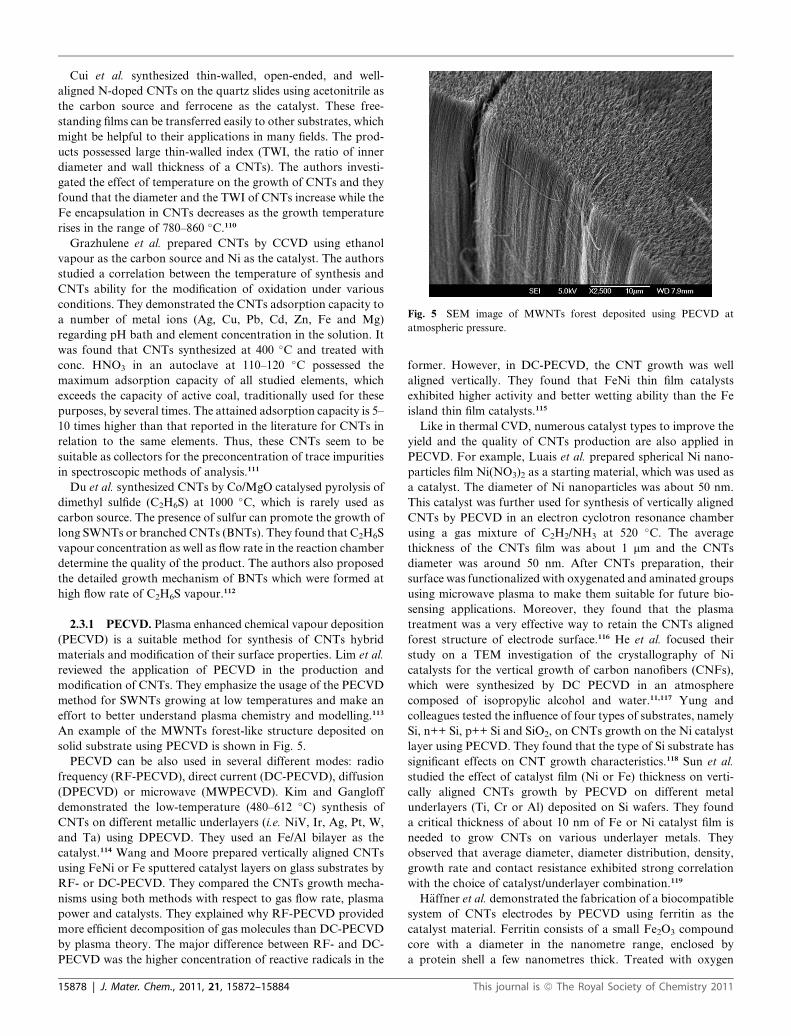
Fig. 5 SEM image of MWNTs forest deposited using PECVD at
atmospheric pressure.
Cui et al. synthesized thin-walled, open-ended, and well-
aligned N-doped CNTs on the quartz slides using acetonitrile as
the carbon source and ferrocene as the catalyst. These free-
standing films can be transferred easily to other substrates, which
might be helpful to their applications in many fields. The prod-
ucts possessed large thin-walled index (TWI, the ratio of inner
diameter and wall thickness of a CNTs). The authors investi-
gated the effect of temperature on the growth of CNTs and they
found that the diameter and the TWI of CNTs increase while the
Fe encapsulation in CNTs decreases as the growth temperature
rises in the range of 780–860 �C.110
Grazhulene et al. prepared CNTs by CCVD using ethanol
vapour as the carbon source and Ni as the catalyst. The authors
studied a correlation between the temperature of synthesis and
CNTs ability for the modification of oxidation under various
conditions. They demonstrated the CNTs adsorption capacity to
a number of metal ions (Ag, Cu, Pb, Cd, Zn, Fe and Mg)
regarding pH bath and element concentration in the solution. It
was found that CNTs synthesized at 400 �C and treated with
conc. HNO3 in an autoclave at 110–120 �C possessed the
maximum adsorption capacity of all studied elements, which
exceeds the capacity of active coal, traditionally used for these
purposes, by several times. The attained adsorption capacity is 5–
10 times higher than that reported in the literature for CNTs in
relation to the same elements. Thus, these CNTs seem to be
suitable as collectors for the preconcentration of trace impurities
in spectroscopic methods of analysis.111
Du et al. synthesized CNTs by Co/MgO catalysed pyrolysis of
dimethyl sulfide (C2H6S) at 1000 �C, which is rarely used as
carbon source. The presence of sulfur can promote the growth of
long SWNTs or branched CNTs (BNTs). They found that C2H6S
vapour concentration as well as flow rate in the reaction chamber
determine the quality of the product. The authors also proposed
the detailed growth mechanism of BNTs which were formed at
high flow rate of C2H6S vapour.112
2.3.1 PECVD. Plasma enhanced chemical vapour deposition
(PECVD) is a suitable method for synthesis of CNTs hybrid
materials and modification of their surface properties. Lim et al.
reviewed the application of PECVD in the production and
modification of CNTs. They emphasize the usage of the PECVD
method for SWNTs growing at low temperatures and make an
effort to better understand plasma chemistry and modelling.113
An example of the MWNTs forest-like structure deposited on
solid substrate using PECVD is shown in Fig. 5.
PECVD can be also used in several different modes: radio
frequency (RF-PECVD), direct current (DC-PECVD), diffusion
(DPECVD) or microwave (MWPECVD). Kim and Gangloff
demonstrated the low-temperature (480–612 �C) synthesis of
CNTs on different metallic underlayers (i.e. NiV, Ir, Ag, Pt, W,
and Ta) using DPECVD. They used an Fe/Al bilayer as the
catalyst.114 Wang and Moore prepared vertically aligned CNTs
using FeNi or Fe sputtered catalyst layers on glass substrates by
RF- or DC-PECVD. They compared the CNTs growth mecha-
nisms using both methods with respect to gas flow rate, plasma
power and catalysts. They explained why RF-PECVD provided
more efficient decomposition of gas molecules than DC-PECVD
by plasma theory. The major difference between RF- and DC-
PECVD was the higher concentration of reactive radicals in the
15878 | J. Mater. Chem., 2011, 21, 15872–15884
former. However, in DC-PECVD, the CNT growth was well
aligned vertically. They found that FeNi thin film catalysts
exhibited higher activity and better wetting ability than the Fe
island thin film catalysts.115
Like in thermal CVD, numerous catalyst types to improve the
yield and the quality of CNTs production are also applied in
PECVD. For example, Luais et al. prepared spherical Ni nano-
particles film Ni(NO3)2 as a starting material, which was used as
a catalyst. The diameter of Ni nanoparticles was about 50 nm.
This catalyst was further used for synthesis of vertically aligned
CNTs by PECVD in an electron cyclotron resonance chamber
using a gas mixture of C2H2/NH3 at 520 �C. The average
thickness of the CNTs film was about 1 mm and the CNTs
diameter was around 50 nm. After CNTs preparation, their
surface was functionalized with oxygenated and aminated groups
using microwave plasma to make them suitable for future bio-
sensing applications. Moreover, they found that the plasma
treatment was a very effective way to retain the CNTs aligned
forest structure of electrode surface.116 He et al. focused their
study on a TEM investigation of the crystallography of Ni
catalysts for the vertical growth of carbon nanofibers (CNFs),
which were synthesized by DC PECVD in an atmosphere
composed of isopropylic alcohol and water.11,117 Yung and
colleagues tested the influence of four types of substrates, namely
Si, n++ Si, p++ Si and SiO2, on CNTs growth on the Ni catalyst
layer using PECVD. They found that the type of Si substrate has
significant effects on CNT growth characteristics.118 Sun et al.
studied the effect of catalyst film (Ni or Fe) thickness on verti-
cally aligned CNTs growth by PECVD on different metal
underlayers (Ti, Cr or Al) deposited on Si wafers. They found
a critical thickness of about 10 nm of Fe or Ni catalyst film is
needed to grow CNTs on various underlayer metals. They
observed that average diameter, diameter distribution, density,
growth rate and contact resistance exhibited strong correlation
with the choice of catalyst/underlayer combination.119
H€affner et al. demonstrated the fabrication of a biocompatible
system of CNTs electrodes by PECVD using ferritin as the
catalyst material. Ferritin consists of a small Fe2O3 compound
core with a diameter in the nanometre range, enclosed by
a protein shell a few nanometres thick. Treated with oxygen
This journal is ª The Royal Society of Chemistry 2011

plasma, amino acids around the ferritin cores were removed, the
iron cores were automatically separated from each other and
dense vertically aligned CNTs grew from the well separated iron
cores. For possible application of these CNTs electrodes in
neuroimplants, which is based on flexible temperature sensitive
substrates (like artificial mica), it is important to reach low
temperatures during the preparation process (down to 450 �C).120
Pd was also tested as a catalyst material in the work of Vol-
lebregt et al., who prepared vertically self-aligned CNTs and
CNFs. The authors compared two preparation methods with
various conditions and catalysts (Pd, Ni, Fe, Co) as follows:
PECVD at 450 �C to 500 �C and atmospheric-pressure chemical
vapour deposition (APCVD) between 450 �C and 640 �C. High-
density self-aligned CNTs were obtained using APCVD and Pd
as the catalyst, while Co and Fe resulted in random growth.
TEM revealed that the CNTs grown by Pd with PECVD formed
large bundles of tubes, while Ni formed large-diameter CNFs.
The authors found that the CNTs grown using Pd or Ni were of
low quality compared with those grown by Co and Fe.121
However, some works were published with no usage of cata-
lysts for CNTs growing. Qu and colleagues prepared new hybrid
material consisting of spontaneous assembly of carbon nano-
spheres on aligned or nonaligned SWNTs using the PECVD
method. The carbon nanospheres were formed with a uniform
size of 30–60 nm. The formation of these spheres is a catalyst-free
process and strongly depends on the applied plasma power and
other factors. This heterojunction structure based on different
types of carbon seems to be promising as a building complex
system for various applications.122
Analogous to various catalysts, different substrates for CNTs
preparation can be also used in the PECVD process. For
example, Duy et al. reported the fabrication of CNTs on Ni-
coated stainless steel or Si substrates using DC-PECVD. The
synthesized CNTs have a diameter of about 30 nm and a length
of about 1.2 mm. They found that CNTs grown on the stainless
steel substrates were more uniform compared with those grown
on the Si substrates. Moreover, they showed the potential of
CNTs in field emission applications, especially CNT-based cold-
cathode X-ray tubes.123
Jang and Ahn fabricated flexible thin film transistors (TFT)
with randomly oriented single-walled SWNTs, which were
synthesized selectively on a designed array of catalyst photore-
sists using the PECVD method. The process involves SWNTs
growth on SiO2/Si substrates. This might be of interest for
various applications of SWNTs in flexible electronics.124 Ono
et al. also prepare TFTwith a carbon CNTs network as a channel
using grid-inserted PECVD.125 Yang et al. synthesized two types
of hybrid carbon materials by RF-PECVD: the tree-CNTs with
branches of different diameters using ferrocene powder as the
catalyst and the wing-like CNTs with graphitic-sheets of
different densities using Co or Ni thin film coated on the surface
of Ti thin film (20 nm). In both cases, Si(100) was used as the
substrate. They found that both the tree- and wing-like CNTs
exhibited lower turn-on field and higher emission current density
than the pristine CNTs, which can be ascribed to the effects of
branch size, crystal orientation, and graphitic-sheet density.126
Seo et al. investigated the growth of metal-free MWNTs on
Corning glass substrates with a microwave PECVD (MPECVD)
method using methane and hydrogen gases. An amorphous
This journal is ª The Royal Society of Chemistry 2011
carbon layer deposited with RF magnetron sputtering was used
as a catalyst to grow metal-free CNTs. The catalyst layer was
pretreated using H2 plasma at 600 �C for 3 min and the CNTs
grew with the different thickness of the catalyst layer for 30 min
at 600 �C.127 Bu and Oei also used Corning glass as a substrate
for vertically aligned CNTs deposition using PECVD. MWNTs
grew by flow carbon-containing gas over silicon substrates
coated with Ni catalyst and indium tin oxide diffusion barrier at
temperature over 700 �C. They functionalized the CNTs surface
with 1H,1H-2H,2H perfluorodecyl-trichlorosilane and hexane
mixture in order to provide protective hydrophobic surface
coating. Such self-cleaning CNTs coated glass is ideal for UV-
blocking applications, such as UV inhibitors in windows.128
A reproducible high-yield purification process of MWNTs by
thermal annealing in ultrapure oxygen was developed by Bu, who
prepared vertically aligned MWNTs by PECVD, using acetylene
and ammonia at 650 �C.129
2.3.2 CVD methods for uniform vertically aligned CNTs
synthesis. The growth of vertically aligned carbon nanotube
forests is studied extensively because it represents one of the
highest yield methods of nanotube growth.130 The aim of several
works is to fabricate vertically aligned CNTs with homogeneous
distribution on the surfaces and high uniformity. It is evident to
use nanolithography to create pattern of the catalyst on the
surface on which CNTs are formed using CVD methods. In the
work of Kim et al., the Si wafer was used as a substrate and Ni as
a catalyst deposited on a diffusion barrier from Ni/Ti. Ni dots
catalyst of 1.6 mm and about 200 nmwas patterned using UV and
e-beam lithography, respectively. ThemethodofCNTs formation
uses the triode PECVD reactor with gas ratio C2H2/(H2 or NH3)
at 620 �C. The positive ions in the cathode sheath of the plasma
can force the CNTs to grow perpendicular to the substrate. The
diameter of created CNTs depended on Ni dots size.131
Yamada et al. used high efficiency water-assisted CVD
synthesis of vertically aligned DWNTs forests with heights of up
to 2.2 mm using Fe catalyst. They achieved CNTs with a carbon
purity of 99.95%.132
Very interesting methods are the ones which use non-litho-
graphic techniques. The most frequently used method of aligned
CNTs formation (Fig. 6) is the usage of nanoporous anodized
aluminium oxide (AAO) as template for CNTs growth. In the
work of Kim et al.,133 the CNTs were grown on AAO/Si
substrate. A catalytic metal layer was formed on the Si wafer by
direct deposition. Two types (A and B) of nanoporous
aluminium templates were used for the study of the growth
characteristics of CNTs. Type A was aluminium of 500 nm
thickness, which was deposited on a silicon wafer. Type B was
aluminium on Co-coated silicon wafer. The thickness of the Co-
layer was 100 �A. The pore diameter and pore depth was
approximately 33 nm and 210 nm for Type A and 5 nm and 220
nm for Type B, respectively. After the pore widening process, the
pore was enlarged to approximately 60 nm and 33 nm for Type A
and Type B, respectively. The CNTs growth was carried out on
the AAO at temperature below 550 �C by DC-PECVD. An
acetylene gas was used as a carbon source and an ammonia gas
was used as a dilution and catalytic gas. The DC plasma was
applied to grow vertically aligned CNTs. The CNT growth with
PECVD on Type A was quite different from the CNT growth
J. Mater. Chem., 2011, 21, 15872–15884 | 15879

Fig. 6 Process of CNTs growth using the AAO template.
with thermal CVD because CNTs were not grown on the AAO/Si
barrier. Graphitization of the CNTs was very poor compared to
the CNTs grown on glass substrate using thermal CVD. The
CNTs grown on the barrier between pores do not look like
nanotubes but carbon nanofibers. In the case of Type B the
length of CNT is almost the same as the pore depth because
CNTs did not grow on the AAO/Si barrier, but only on the
catalyst on the bottom of the pores. CNTs grew on AAO/Si
without a catalyst, while there was no overgrowth of CNTs on
AAO/Si with a catalyst. In synthesis of CNTs using AAO
template with/without a Co layer, both alumina and Co can work
as a catalyst with flowing acetylene.
Similar work employing CVD on an AAO template is
described by Sui et al.134 The authors found the pores in
templates had diameters of 24 nm and 86 nm according to the
anodizing voltage and acid used. Porous anodic alumina film in
this case also acts as both the catalyst and the template in the
formation of CNTs by thermal decomposition of acetylene. The
MWNTs grew by CVD in a tubular stove with a gas-flowmixture
of N2/C2H2 (90 : 10) with a rate of 100 ml min�1 for 2 h at 650 �C.The walls of both CNTs types consisted of numerous stacked
flakes, which is different from that of MWNTs made by arc-
discharging and other CVD methods. Both kinds of CNTs had
the same wall structures. After treatment of templates in boiling
water before CVD, different results were obtained. The CNTs
with the bamboo-like appearances grow from the template with
24 nm pore diameter. However solid carbon nanofibers rather
than CNTs were obtained in the template with 86 nm pore
diameter. If the temperature of the CVD process decreased to
550 �C, only CNTs were formed and there was no evident effect
of boiling in water. When the CVD temperature decreased
further to 500 �C, no CNTs or nanofibers were formed.
15880 | J. Mater. Chem., 2011, 21, 15872–15884
Lee et al. also described a CVD process with AAO templates to
fabricate CNTs.135 In their work, CNTs were synthesized
through the decomposition of acetylene/argon at 800 �C for 20
min in the infrared tube furnace. In this case at first, a niobium
layer of 200 nm thickness was deposited on an oxidized silicon
wafer before AAO template formation. After aluminium was
completely consumed, the niobium layer was anodized to create
an oxide catalyst on the bottom of the template. Average pore
diameter in the template was 70 nm. CNTs formed in the
template had the same diameter as pores. If plasma treatment in
oxygen for 10 min (100 W of RF power) is applied, the uniform
length of the CNTs is obtained after dissolution of the template.
Chang et al. proposed a simple, inexpensive and reproducible
method to produce nanoscale electrode arrays in large areas.
They prepared vertically aligned MWNTs with a bamboo-like
structure and high density on a large area of plain quartz
substrates using PECVD. Ammonia and acetylene were used as
the etchant gases and the carbon source, respectively. MWNTs
were grown on a TiN coated quartz plate with Fe catalysts
patterned by UV nanoimprint lithography (NIL). Patterned
catalysts allow the precise placement of individual CNT elec-
trodes on the substrate. The prepared electrodes had diameters
ranging from 50 nm to 100 nm and lengths of about 300 nm. In
addition, they investigated the biocompatibility by cell culturing
on the fabricated CNTs/quartz template for potential
bioapplications.136
2.3.3 Liquid pyrolysis. The aerosol pyrolysis process is
a catalytic CVD-based method involving pyrolysis of mixed
liquid aerosols composed of both liquid hydrocarbon and cata-
lyst precursor. Byeon and colleagues developed a new aerosol-
assisted chemical vapour deposition (AACVD) process to
synthesize vertically aligned CNTs arrays with outstanding
height (4.38 mm) with very low metal contents in a short time (20
min) without supporting materials and water-assistance. An
essential part of this technique was in situ formation of metal
catalyst nanoparticles via pyrolysis of ferrocene–ethanol aerosol
right before CNTs synthesis.137
Jeong et al. presented an ultrasonic evaporator atomizing the
mixed liquid solution for MWNTs production by the thermal
pyrolysis process. They produced aligned and clean CNTs which
can be easily controlled in a cost-effective manner.138 A similar
approach for nitrogen-doped CNTs with the tunable structure
and high yield production by ultrasonic spray pyrolysis was done
by Liu et al.139 Khatri et al. reported SWNTs synthesis using
ethanol and bimetallic catalyst of cobalt and molybdenum
acetates by an ultrasonic spray pyrolysis method on silicon
substrates at 850 �C.140 Later, this author focused his research on
zeolites powder as catalyst supporting material for SWNTs
production using ultrasonic spray pyrolysis.141 In another study,
Camarena and colleagues prepared MWNTs by spray pyrolysis
using toluene as the carbon source and ferrocene as the cata-
lyst.142 Sadeghian reported preparation of MWNTs by spray
pyrolysis, using hexane as a carbon source and ferrocene as
a catalyst precursor.143 Clean and aligned MWNTs produced by
aerosol pyrolysis of mixed liquid aerosols composed of both
liquid hydrocarbon (toluene or cyclohexane) and catalyst
precursor (ferrocene) were also reported by Pinault et al.144 In
another work, Nebol’sin and Vorob’ev studied CNTs growth via
This journal is ª The Royal Society of Chemistry 2011

catalytic pyrolysis of acetylene. They found that surface free
energy plays a key role in determining the catalytic activity of the
liquid droplet on the CNT tip and is responsible for the constant
nanotube diameter.145 An interesting paper describing the usage
of a less common liquid carbon source, namely various pinene
components isolated from turpentine, for MWNTs production
by spray pyrolysis was recently published by Lara-Romero
et al.146 Next, a green natural carbon source for CNTs fabrica-
tion, neem oil extracted from the seeds of the neem-Azadirachta
indica, was tested in the work of Kumar et al.147 Similarly,
coconut oil can be also used as a natural renewable precursor for
MWNTs synthesis.148
Quan et al. reported a new and interesting way of CNTs
synthesis through waste pyrolysis oil. This process is based on
treatment of waste pyrolysis liquid from printed circuit board
(PCB) waste, which contains high concentrations of phenol and
phenol derivatives. Hence, it can be applied as a carbon source in
the preparation of advanced carbonaceous materials like CNTs.
First, the pyrolysis oil is prepared by pyrolysis of PCB waste at
600 �C. In the second step, the product is polymerized in
a formaldehyde solution to synthesize pyrolysis oil-based resin
which is used as the precursor CNTs. Finally, this resin was
mixed with ferrocene and homogenized in ethanol. After alcohol
evaporation, the mixture was ground into fine powder, loaded on
a ceramic boat and placed inside a stainless steel tubular reactor.
The mixture was heated to 200 �C in air with 1 h soaking time,
and then up to 900 �C in a flow of N2 with holding periods for 1 h
at 900 �C. The resulting CNTs had hollow cores with outer
diameter of 338 nm and wall thickness of 86 nm and most of
them were filled with metal nanoparticles or nanorods. X-Ray
diffraction revealed that CNTs had an amorphous structure.149
Ionescu et al. presented, that for a safe and easy way to scale
up the CNTs growth, which is applicable in industrial produc-
tion, it is possible to use spray pyrolysis CVD in the absence of
hydrogen at low carrier gas flow rates and at relatively low
synthesis temperature (typically 750 �C). They concluded that
this approach promises great potential in building various
nanodevices with different electron conducting requirements.150
2.3.4 Solid state pyrolysis. Nowadays, solid state pyrolysis
for CNTs synthesis is less frequently used compared to previ-
ously mentioned ones. Kucukayan and colleagues synthesized
MWNTs through pyrolysis of the sulfuric acid-carbonized
byproduct of sucrose. They observed the presence of sulfur in
catalyst particles trapped inside nanotubes, but no sulfur was
present in the side-walls of the CNTs.151 Clauss et al. thermally
decomposed two nitrogen-rich iron salts, ferric ferrocyanide
(Prussian Blue, ‘‘PB’’) and iron melonate (‘‘FeM’’) in a micro-
wave oven, which was used to heat a molybdenum wire after
being coated with the precursor and protected from ambient
atmosphere. While the PB-precursor did not give any nanotube-
containing products, the FeM-precursor furnished tubular
carbon nanostructures in a reproducible manner. This result may
be due to the graphite-like nature of the melonate anions pre-
sented in FeM.152 Kuang et al. synthesized straight CNTs in large
scale through thermal CVD by pyrolysis of two mixed metal
phthalocyanines with a certain amount of S at 800–950 �C. Theas-synthesized CNTs were 15–35 nm in diameter and 200–800
nm in length, quite straight and well-graphitized with nearly no
This journal is ª The Royal Society of Chemistry 2011
defects. Two kinds of mixed transition metal phthalocyanines (M
(II)Pc, M ¼ Fe, Co) were used as the carbon source as well as
catalysts favoring the growth of the straight CNTs.153 Du et al.
prepared MWNTs through the solid-phase transformation of
metal-containing glass-like carbon nanoparticles by heating at
temperatures of 800–1000 �C. Frommicroscopic observations on
the morphologies and structures of the nanotubes and various
intermediate objects, it is shown that the transformation occurs
by nanoparticles first assembling into wire-like nanostructures,
and then transforming into nanotubes via particle-particle coa-
lescence and structural crystallization.154 El Hamaoui studied the
influence of novel polyphenylene-metal complexes to synthesis of
various carbon nanoparticles (CNPs) including graphitic CNTs,
graphitic carbon rods, and carbon-metal hybrid particles by
solid-state pyrolysis of these complexes. The ultimate structures
of the CNPs were found to depend on the structure and
composition of the starting compounds. Precursors containing
graphenes always result in graphitic CNTs in high yield, whereas
dendritic precursors given rodlike carbon materials. Alterna-
tively, linear oligo(arylethylene) precursors afford mostly
carbon-metal hybrids with large amounts of amorphous
carbon.155
2.4 Flame pyrolysis
This technique is presented very uniquely by the research group
of Liu et al. as a new method for mass CNTs production using
simple equipment and experimental conditions. The authors
called it V-type pyrolysis flame. They captured successfully
CNTs with less impurities and high yield using carbon monoxide
as the carbon source. Acetylene/air premixed gas provided heat
by combustion. Pentacarbonyl was used as the catalyst and
hydrogen/helium premixed gas acted as diluted and protection
gas. The diameter of obtained CNTs was approximately between
10 nm and 20 nm, and its length was dozens of microns.156
Moreover they studied the effect of sampling time, hydrogen and
helium to the CNTs growth process.157–159
2.5 Bottom-up organic approach
The bottom-up approach to integrate vertically PECVD grown
MWNTs into multilevel interconnects in silicon integrated-
circuit manufacturing from patterned catalyst spot was reported
first by Li et al.160
More recently, Jasti and Bertozzi described in their frontier
article the potential advantages, recent advances, and challenges
that lie ahead for the bottom-up organic synthesis of homoge-
neous CNTs with well-defined structures.161 Current synthetic
methods used for CNTs fabrication produce mixtures of struc-
tures with varying physical properties. Jasti and Bertozzi
demonstrated the CNTs synthesis with control of chirality, which
relies on utilizing hoop-shaped carbon macrocycles, i.e. small
fragments of CNTs that retain information regarding chirality
and diameter, as templates for CNTs synthesis (Fig. 7). Their
strategy lies in two basic areas: the synthesis of aromatic
macrocyclic templates and the development of polymerization
reactions to extend these templates into longer CNTs. This
approach is particularly attractive because it can be used for
synthesis of both zigzag and armchair CNTs of different
J. Mater. Chem., 2011, 21, 15872–15884 | 15881

Fig. 7 Bottom-up, organic synthesis approach to CNTs with discrete
chirality, modified according to ref. 161
diameters, as well as of chiral CNTs with various helical pitches.
For example, a (5, 5) armchair CNT can be constructed by fusing
additional phenyl rings to [5]cycloparaphenylene (Fig. 7a). In
similar fashion, a (10, 0) zigzag CNT can be constructed from
[10]cyclacene (Fig. 7b).
Since the publication work of Jasti and Bertozzi, several
approaches for carbon macrocycles as a step toward the bottom-
up synthesis of CNTs with selective chirality have been reported.
Omachi et al. reported a modular and size-selective synthesis of
[14]-, [15]-, and [16]cycloparaphenylenes for selective synthesis of
[n,n] type SWNTs.162 Concise synthesis of [12]cyclo-
paraphenylene and its crystal structure was presented by Segawa
et al.163 A simple and realistic model for the shortest sidewall
segments of chiral SWNTs has been designed, and one of the
chiral carbon nanorings, cyclo[13]paraphenylene-2,6-naph-
thylene for chemical synthesis of chiral CNTs has been success-
fully synthesized by Omachi et al.164 Selective and random
synthesis of a [8]–[13] cycloparaphenylenes mixture was prepared
in good combined yields by mixing biphenyl and terphenyl
precursors with platinum sources by Iwamoto et al.165 Finally
Fort and Scott also presented interesting groundwork for the
selective solvent-free growth of uniform diameter armchair
CNTs by gas-phase Diels–Alder cycloaddition of benzyne to an
aromatic hydrocarbon bay region on the rims of suitable cylin-
drical hydrocarbon templates followed by rearomatizations and
thermal cyclodehydrogenations to join adjacent benzo groups.166
3. Conclusions
Although the growth mechanism of CNTs is not exactly known,
new synthesis methods for higher yield, higher purity and low
defects of produced CNTs are main points of investigation which
are pushed forward by the prospering fields of nanotechnology
and nanoscience that have many ideas of possible applications.
In this paper, we reviewed the history, types, structures and
especially the different synthesis methods for CNTs preparation
including arc discharge, laser ablation and CVD and some new
approaches of synthesis regarding the various CNTs types,
namely MWNTs, SWNTs and DWNTs. The problem of puri-
fication of CNTs has been discussed as well.
15882 | J. Mater. Chem., 2011, 21, 15872–15884
Special emphasis is given to CVD and PECVD techniques as
the most utilized methods in the last few years. Moreover, we
mentioned some rarely used ways of arc discharge deposition
which involve arc discharge in liquid solutions contrary to the
standard use of deposition in a gas atmosphere. In addition, the
methods for uniform vertically aligned CNTs synthesis using
lithographic techniques for catalyst deposition as well as
a method utilizing a nanoporous anodized aluminium oxide as
a pattern for selective CNTs grown are reported too.
Acknowledgements
This review was supported by the Czech grant projects GACR
102/09/P640, NANIMEL GACR 102/08/1546 and GACR P205/
10/1374.
References
1 L. V. Radushkevich and V. M. Lukyanovich, Zh. Fiz. Khim., 1952,26, 88–95.
2 A. Oberlin, M. Endo and T. Koyama, J. Cryst. Growth, 1976, 32,335–349.
3 S. Iijima, Nature, 1991, 354, 56–58.4 S. Iijima and T. Ichihashi, Nature, 1993, 363, 603–605.5 D. S. Bethune, C. H. Kiang, M. S. Devries, G. Gorman, R. Savoy,J. Vazquez and R. Beyers, Nature, 1993, 363, 605–607.
6 M. S. Dresselhaus, G. Dresselhaus and R. Saito, Carbon, 1995, 33,883–891.
7 Biosensing Using Nanomaterials, ed. A. Merkoci, Wiley, New Jersey,2009.
8 Carbon Nanotubes, ed. A. Jorio, G. Dresselhaus and M. S.Dresselhaus, Springer-Verlag, Berlin, 2008.
9 C. Laurent, E. Flahaut and A. Peigney,Carbon, 2010, 48, 2994–2996.10 J. G. Duque, A. N. G. Parra-Vasquez, N. Behabtu, M. J. Green,
A. L. Higginbotham, B. K. Price, A. D. Leonard, H. K. Schmidt,B. Lounis, J. M. Tour, S. K. Doorn, L. Cognet and M. Pasquali,ACS Nano, 2010, 4, 3063–3072.
11 Z. B. He, J. L. Maurice, C. S. Lee, C. S. Cojocaru and D. Pribat,Arabian J. Sci. Eng., Sect. B, 2010, 35, 19–28.
12 H. Barankova and L. Bardos, Polym. Int., 2008, 57, A1.13 T. Nozaki and K. Okazaki, Plasma Processes Polym., 2008, 5, 301–
321.14 J. H. Ting, J. Y. Lyu, F. Y. Huang, T. L. Li, C. L. Hsu, C. W. Liu
and IEEE, in 2008 17th Biennial University/Government/IndustryMicro-Nano Symposium, Proceedings, IEEE, New York, 2008, pp.157–160.
15 S. Wei, W. P. Kang, J. L. Davidson, B. K. Choi and J. H. Huang, J.Vac. Sci. Technol., B: Microelectron. Nanometer Struct.–Process.,Meas., Phenom., 2006, 24, 1190–1196.
16 L. Zajickova,M. Elias, O. Jasek, V. Kudrle, Z. Frgala, J. Matejkova,J. Bursik and M. Kadlecikova, Plasma Phys. Controlled Fusion,2005, 47, B655–B666.
17 C. J. Unrau, R. L. Axelbaum and C. S. Lo, J. Phys. Chem. C, 2010,114, 10430–10435.
18 I. Kruusenberg, N. Alexeyeva, K. Tammeveski, J. Kozlova,L. Matisen, V. Sammelselg, J. Solla-Gull�on and J. M. Feliu,Carbon, 2011, 49, 4031–4039.
19 N. M. Mubarak, F. Yusof and M. F. Alkhatib, Chem. Eng.J. (Amsterdam, Neth.), 2011, 168, 461–469.
20 T. W. Ebbesen and P. M. Ajayan, Nature, 1992, 358, 220–222.21 M. Wang, X. L. Zhao, M. Ohkohchi and Y. Ando, Fullerene Sci.
Technol., 1996, 4, 1027–1039.22 X. L. Zhao, M. Wang, M. Ohkohchi and Y. Ando, Jpn. J. Appl.
Phys., Part 1, 1996, 35, 4451–4456.23 X. Zhao, M. Ohkohchi, M. Wang, S. Iijima, T. Ichihashi and
Y. Ando, Carbon, 1997, 35, 775–781.24 X. Zhao, M. Ohkohchi, H. Shimoyama and Y. Ando, J. Cryst.
Growth, 1999, 198, 934–938.25 K. Shimotani, K. Anazawa, H. Watanabe and M. Shimizu, Appl.
Phys. A: Mater. Sci. Process., 2001, 73, 451–454.
This journal is ª The Royal Society of Chemistry 2011

26 Y. Jiang, H. Wang, X. F. Shang, Z. H. Li and M. Wang, Inorg.Mater., 2009, 45, 1237–1239.
27 N. Parkansky, R. L. Boxman, B. Alterkop, I. Zontag, Y. Lereah andZ. Barkay, J. Phys. D: Appl. Phys., 2004, 37, 2715–2719.
28 Y. Y. Tsai, J. S. Su, C. Y. Su and W. H. He, J. Mater. Process.Technol., 2009, 209, 4413–4416.
29 S. H. Jung, M. R. Kim, S. H. Jeong, S. U. Kim, O. J. Lee, K. H. Lee,J. H. Suh and C. K. Park, Appl. Phys. A: Mater. Sci. Process., 2003,76, 285–286.
30 N. Sornsuwit and W. Maaithong, Int. J. Precis. Eng. Manuf., 2008,9, 18–21.
31 L. A. Montoro, R. C. Z. Lofrano and J. M. Rosolen, Carbon, 2005,43, 200–203.
32 J. J. Guo, X. M. Wang, Y. L. Yao, X. W. Yang, X. G. Liu andB. S. Xu, Mater. Chem. Phys., 2007, 105, 175–178.
33 G. Xing, S. L. Jia and Z. Q. Shi, New Carbon Mater., 2007, 22, 337–341.
34 P. M. Ajayan, J. M. Lambert, P. Bernier, L. Barbedette, C. Colliexand J. M. Planeix, Chem. Phys. Lett., 1993, 215, 509–517.
35 S. Seraphin, D. Zhou, J. Jiao, M. A. Minke, S. Wang, T. Yadav andJ. C. Withers, Chem. Phys. Lett., 1994, 217, 191–198.
36 Y. Saito, M. Okuda, N. Fujimoto, T. Yoshikawa, M. Tomita andT. Hayashi, Jpn. J. Appl. Phys., Part 2, 1994, 33, L526–L529.
37 D. Zhou, S. Seraphin and S.Wang,Appl. Phys. Lett., 1994, 65, 1593–1595.
38 Y. Saito, K. Nishikubo, K. Kawabata and T. Matsumoto, J. Appl.Phys., 1996, 80, 3062–3067.
39 Y. Saito, M. Okuda and T. Koyama, Surf. Rev. Lett., 1996, 3, 863–867.
40 B. Chen, X. Zhao, S. Inoue and Y. Ando, J. Nanosci. Nanotechnol.,2010, 10, 3973–3977.
41 B. Chen, S. Inoue and Y. Ando, Diamond Relat. Mater., 2009, 18,975–978.
42 W. W. Fan, J. Zhao, Y. K. Lv, W. R. Bao and X. G. Liu, J. WuhanUniv. Technol., Mater. Sci. Ed., 2010, 25, 194–196.
43 H. F. Wang, Z. H. Li, S. Inoue and Y. Ando, J. Nanosci.Nanotechnol., 2010, 10, 3988–3993.
44 Z. J. Li, P. Liu, B. Zhao, H. Y. Wang and Y. F. Zhang, Carbon,2008, 46, 1819–1822.
45 J. L. Hutchison, N. A. Kiselev, E. P. Krinichnaya, A. V. Krestinin,R. O. Loutfy, A. P. Morawsky, V. E. Muradyan, E. D. Obraztsova,J. Sloan, S. V. Terekhov andD. N. Zakharov,Carbon, 2001, 39, 761–770.
46 T. Sugai, H. Yoshida, T. Shimada, T. Okazaki and H. Shinohara,Nano Lett., 2003, 3, 769–773.
47 H. J. Huang, H. Kajiura, S. Tsutsui, Y. Murakami and M. Ata,J. Phys. Chem. B, 2003, 107, 8794–8798.
48 J. S. Qiu, Z. Y. Wang, Z. B. Zhao and T. H. Wang, Fuel, 2007, 86,282–286.
49 H. X. Qiu, Z. J. Shi, L. H. Guan, L. P. You, M. Gao, S. L. Zhang,J. S. Qiu and Z. N. Gu, Carbon, 2006, 44, 516–521.
50 Q. F. Liu, W. C. Ren, F. Li, H. T. Cong and H. M. Cheng, J. Phys.Chem. C, 2007, 111, 5006–5013.
51 L. X. Li, F. Li, C. Liu and H. M. Cheng, Carbon, 2005, 43, 623–629.52 Y. Ando, X. Zhao, H. Kataura, Y. Achiba, K. Kaneto,
M. Tsuruta, S. Uemura and S. Iijima, Diamond Relat. Mater.,2000, 9, 847–851.
53 S. K. Pillai, W. G. Augustyn, M. H. Rossouw and R. I. McCrindle,J. Nanosci. Nanotechnol., 2008, 8, 3539–3544.
54 P. Chaturvedi, P. Verma, A. Singh, P. K. Chaudhary, Harsh andP. K. Basu, Def. Sci. J., 2008, 58, 591–599.
55 K. MacKenzie, O. Dunens and A. T. Harris, Sep. Purif. Technol.,2009, 66, 209–222.
56 S. K. Pillai, S. S. Ray and M. Moodley, J. Nanosci. Nanotechnol.,2007, 7, 3011–3047.
57 K. Saeed, J. Chem. Soc. Pak., 2010, 32, 559–564.58 T. Guo, P. Nikolaev, A. Thess, D. T. Colbert and R. E. Smalley,
Chem. Phys. Lett., 1995, 243, 49–54.59 T. Ikegami, F. Nakanishi, M. Uchiyama and K. Ebihara, Thin Solid
Films, 2004, 457, 7–11.60 A. P. Bolshakov, S. A. Uglov, A. V. Saveliev, V. I. Konov,
A. A. Gorbunov, W. Pompe and A. Graff, Diamond Relat. Mater.,2002, 11, 927–930.
61 H. Y. Zhang, Y. Ding, C. Y. Wu, Y. M. Chen, Y. J. Zhu, Y. Y. Heand S. Zhong, Phys. B (Amsterdam, Neth.), 2003, 325, 224–229.
This journal is ª The Royal Society of Chemistry 2011
62 R. Marchiori, W. F. Braga, M. B. H. Mantelli and A. Lago,J. Mater. Sci., 2010, 45, 1495–1502.
63 L. L. Lebel, B. Aissa, M. A. El Khakani and D. Therriault, Compos.Sci. Technol., 2010, 70, 518–524.
64 M. Kusaba and Y. Tsunawaki, Thin Solid Films, 2006, 506, 255–258.65 A. A. Stramel, M. C. Gupta, H. R. Lee, J. Yu and W. C. Edwards,
Opt. Lasers Eng., 2010, 48, 1291–1295.66 F. Bonaccorso, C. Bongiorno, B. Fazio, P. G. Gucciardi,
O. M. Marago, A. Morone and C. Spinella, Appl. Surf. Sci., 2007,254, 1260–1263.
67 S. A. Steiner, T. F. Baumann, B. C. Bayer, R. Blume,M. A.Worsley,W. J. MoberlyChan, E. L. Shaw, R. Schlogl, A. J. Hart, S. Hofmannand B. L. Wardle, J. Am. Chem. Soc., 2009, 131, 12144–12154.
68 H. Tempel, R. Joshi and J. J. Schneider, Mater. Chem. Phys., 2010,121, 178–183.
69 R. Smajda, J. C. Andresen, M. Duchamp, R. Meunier,S. Casimirius, K. Hernadi, L. Forro and A. Magrez, Phys. StatusSolidi B, 2009, 246, 2457–2460.
70 S. P. Patole, P. S. Alegaonkar, H. C. Lee and J. B. Yoo, Carbon,2008, 46, 1987–1993.
71 H. R. Byon, H. Lim, H. J. Song and H. C. Choi, Bull. Korean Chem.Soc., 2007, 28, 2056–2060.
72 Y. M. Chen and H. Y. Zhang, in Advances in Composites, ed. J. L.Bu, Z. Y. Jiang and S. Jiao, Trans Tech Publications Ltd, Stafa-Zurich, 2011, Pts 1 and 2, pp. 1560–1563.
73 D. Varshney, B. R. Weiner and G. Morell, Carbon, 2010, 48, 3353–3358.
74 H. D. Kim, J. H. Lee andW. S. Choi, J. Korean Phys. Soc., 2011, 58,112–115.
75 B. Brown, C. B. Parker, B. R. Stoner and J. T. Glass, Carbon, 2011,49, 266–274.
76 Y. Xu, E. Dervishi, A. R. Biris and A. S. Biris,Mater. Lett., 2011, 65,1878–1881.
77 Y. J. Zhu, T. J. Lin, Q. X. Liu, Y. L. Chen, G. F. Zhang, H. F. Xiongand H. Y. Zhang, Mater. Sci. Eng., B, 2006, 127, 198–202.
78 N. Fotopoulos and J. P. Xanthakis, Diamond Relat. Mater., 2010,19, 557–561.
79 O. Lee, J. Jung, S. Doo, S. S. Kim, T. H. Noh, K. I. Kim andY. S. Lim, Met. Mater. Int., 2010, 16, 663–667.
80 R. Sharma, S. W. Chee, A. Herzing, R. Miranda and P. Rez, NanoLett., 2011, 11, 2464–2471.
81 M. Palizdar, R. Ahgababazadeh, A. Mirhabibi, R. Brydson andS. Pilehvari, J. Nanosci. Nanotechnol., 2011, 11, 5345–5351.
82 T. Tomie, S. Inoue, M. Kohno and Y. Matsumura, Diamond Relat.Mater., 2010, 19, 1401–1404.
83 U. Narkiewicz, M. Podsiadly, R. Jedrzejewski and I. Pelech, Appl.Catal., A, 2010, 384, 27–35.
84 D. L. He, H. Li, W. L. Li, P. Haghi-Ashtiani, P. Lejay and J. B. Bai,Carbon, 2011, 49, 2273–2286.
85 Y. Shirazi, M. A. Tofighy, T. Mohammadi and A. Pak, Appl. Surf.Sci., 2011, 257, 7359–7367.
86 G. Atthipalli, R. Epur, P. N. Kumta, M. J. Yang, J. K. Lee andJ. L. Gray, J. Phys. Chem. C, 2011, 115, 3534–3538.
87 H. Li, D. L. He, T. H. Li, M. Genestoux and J. B. Bai, Carbon, 2010,48, 4330–4342.
88 S. Santangelo, G. Messina, G. Faggio, M. Lanza, A. Pistone andC. Milone, J. Mater. Sci., 2010, 45, 783–792.
89 B. Hou, R. Xiang, T. Inoue, E. Einarsson, S. Chiashi, J. Shiomi,A. Miyoshi and S. Maruyama, Jpn. J. Appl. Phys., 2011, 50, 4.
90 Z. Yong, L. Fang and Z. Zhi-hua, Micron, 2011, 42, 547–552.91 B. Skukla, T. Saito, S. Ohmori, M. Koshi, M. Yumura and S. Iijima,
Chem. Mater., 2010, 22, 6035–6043.92 A. S. Afolabi, A. S. Abdulkareem, S. D. Mhlanga and S. E. Iyuke,
J. Exp. Nanosci., 2011, 6, 248–262.93 S. Dumpala, J. B. Jasinski, G. U. Sumanasekera andM. K. Sunkara,
Carbon, 2011, 49, 2725–2734.94 J. Zhu, M. Yudasaka and S. Iijima, Chem. Phys. Lett., 2003, 380,
496–502.95 P. Ramesh, T. Okazaki, R. Taniguchi, J. Kimura, T. Sugai, K. Sato,
Y. Ozeki and H. Shinohara, J. Phys. Chem. B, 2005, 109, 1141–1147.96 T. Hiraoka, T. Kawakubo, J. Kimura, R. Taniguchi, A. Okamoto,
T. Okazaki, T. Sugai, Y. Ozeki, M. Yoshikawa and H. Shinohara,Chem. Phys. Lett., 2003, 382, 679–685.
97 A. Szabo, C. Perri, A. Csato, G. Giordano, D. Vuono andJ. B. Nagy, Materials, 2010, 3, 3092–3140.
J. Mater. Chem., 2011, 21, 15872–15884 | 15883

98 E. Flahaut, C. Laurent and A. Peigney, Carbon, 2005, 43, 375–383.
99 X. Xiang, L. Zhang, H. I. Hima, F. Li and D. G. Evans, Appl. ClaySci., 2009, 42, 405–409.
100 S. C. Lyu, B. C. Liu, C. J. Lee, H. K. Kang, C. W. Yang andC. Y. Park, Chem. Mater., 2003, 15, 3951–3954.
101 D. S. Zhang, L. Y. Shi, J. H. Fang, K. Dai and X. K. Li, Mater.Chem. Phys., 2006, 97, 415–419.
102 D. S. Zhang, L. Y. Shi, J. H. Fang, X. K. Li and K. Dai, Mater.Lett., 2005, 59, 4044–4047.
103 N. Sano, S. Ishimaru and H. Tamaon, Mater. Chem. Phys., 2010,122, 474–479.
104 Q. Jiang, L. J. Song, H. Yang, Z. W. He and Y. Zhao, Electrochem.Commun., 2008, 10, 424–427.
105 B. Scheibe, E. Borowiak-Palen and R. J. Kalenczuk, Mater.Charact., 2010, 61, 185–191.
106 J.-M. Feng, R. Wang, Y.-L. Li, X.-H. Zhong, L. Cui, Q.-J. Guo andF. Hou, Carbon, 2010, 48, 3817–3824.
107 G. Li, Russ. J. Phys. Chem. A, 2010, 84, 1560–1565.108 Z. F. Liu, L. Y. Jiao, Y. G. Yao, X. J. Xian and J. Zhang, Adv.
Mater., 2010, 22, 2285–2310.109 H.-J. Kim, E. Oh, J. Lee, D.-S. Shim and K.-H. Lee, Carbon, 2011,
49, 3717–3722.110 T. X. Cui, R. T. Lv, F. Y. Kang, Q. Hu, J. L. Gu, K. L. Wang and
D. H. Wu, Nanoscale Res. Lett., 2010, 5, 941–948.111 S. S. Grazhulene, A. N. Red’kin, G. F. Telegin, A. V. Bazhenov and
T. N. Fursova, J. Anal. Chem., 2010, 65, 682–689.112 G. H. Du, Y. S. Zhou and B. S. Xu, Mater. Charact., 2010, 61, 427–
432.113 S. H. Lim, Z. Q. Luo, Z. X. Shen and J. Y. Lin,Nanoscale Res. Lett.,
2010, 5, 1377–1386.114 S. M. Kim and L. Gangloff, Phys. E (Amsterdam, Neth.), 2009, 41,
1763–1766.115 H. Wang and J. J. Moore, J. Vac. Sci. Technol., B:
Microelectron. Nanometer Struct.–Process., Meas., Phenom.,2010, 28, 1081–1085.
116 E. Luais, C. Thobie-Gautier, A. Tailleur, M.-A. Djouadi,A. Granier, P. Y. Tessier, D. Debarnot, F. Poncin-Epaillard andM. Boujtita, Electrochim. Acta, 2010, 55, 7916–7922.
117 Z. W. He, Q. Jiang, R. Yang, P. Qi, F. Zhao, H. Yuan and Y. Zhao,Acta Phys.-Chim. Sin., 2010, 26, 1214–1218.
118 K. P. Yung, R. Y. J. Tay, J. Wei, B. K. Tay and ASME, Effects ofSilicon Substrate on the Growth of Carbon Nanotubes, Amer SocMechanical Engineers, New York, 2010.
119 X. H. Sun, K. Li, R. Wu, P. Wilhite, T. Saito, J. Gao andC. Y. Yang, Nanotechnology, 2010, 21, 6.
120 M. H€affner, K. Schneider, B. E. Schuster, B. Stamm, F. Latteyer,M. Fleischer, C. Burkhardt, T. Chasse, A. Stett and D. P. Kern,Microelectron. Eng., 2010, 87, 734–737.
121 S. Vollebregt, J. Derakhshandeh, R. Ishihara, M. Y. Wu andC. I. M. Beenakker, J. Electron. Mater., 2010, 39, 371–375.
122 L. T. Qu, H. Zhang, J. Zhu and L. M. Dai, Nanotechnology, 2010,21, 8.
123 D. Q. Duy, H. S. Kim, D. M. Yoon, K. J. Lee, J. W. Ha,Y. G. Hwang, C. H. Lee and T. C. Bach, Appl. Surf. Sci., 2009,256, 1065–1068.
124 S. J. Jang and J. H. Ahn, Flexible Thin Flim Transistor Using PrintedSingle-Walled Carbon Nanotubes, Ieee, New York, 2010.
125 Y. Ono, S. Kishimoto, Y. Ohno and T. Mizutani, Nanotechnology,2010, 21, 4.
126 G. M. Yang, C. C. Yang, Q. Xu, W. T. Zheng and S. Li, J. SolidState Chem., 2009, 182, 3393–3398.
127 J. K. Seo, H. Jung, J. H. Lee, S. Y. Deok, J. J. Young andW. S. Choi, Curr. Appl. Phys., 2010, 10, S447–S450.
128 I. Y. Y. Bu and S. P. Oei, Appl. Surf. Sci., 2010, 256, 6699–6704.129 I. Y. Y. Bu, K. Hou and D. Engstrom,Diamond Relat. Mater., 2011,
20, 746–751.130 P. Vinten, J. Bond, P. Marshall, J. Lefebvre and P. Finnie, Carbon,
2011, In press, DOI: 10.1016/j.carbon.2011.02.017.131 D. Kim, S. H. Lim, A. J. Guilley, C. S. Cojocaru, J. E. Bouree,
L. Vila, J. H. Ryu, K. C. Park and J. Jang, Thin Solid Films, 2008,516, 706–709.
132 T. Yamada, T. Namai, K. Hata, D. N. Futaba, K. Mizuno, J. Fan,M. Yudasaka, M. Yumura and S. Iijima,Nat. Nanotechnol., 2006, 1,131–136.
15884 | J. Mater. Chem., 2011, 21, 15872–15884
133 M. J. Kim, J. H. Choi, J. B. Park, S. K. Kim, J. B. Yoo andC. Y. Park, Thin Solid Films, 2003, 435, 312–317.
134 Y. C. Sui, B. Z. Cui, R. Guardian, D. R. Acosta, L. Martinez andR. Perez, Carbon, 2002, 40, 1011–1016.
135 O. J. Lee, S. K. Hwang, S. H. Jeong, P. S. Lee and K. H. Lee, Synth.Met., 2005, 148, 263–266.
136 W. S. Chang, J. W. Kim, D. G. Choi and C. S. Han, Thin Solid Films,2010, 518, 6624–6629.
137 H. Byeon, S. Y. Kim, K. H. Koh and S. Lee, J. Nanosci.Nanotechnol., 2010, 10, 6116–6119.
138 N. Jeong, Y. Seo and J. Lee, Diamond Relat. Mater., 2007, 16, 600–608.
139 J. Liu, Y. Zhang, M. I. Ionescu, R. Li and X. Sun, Appl. Surf. Sci.,2011, 257, 7837–7844.
140 I. Khatri, T. Soga, T. Jimbo, S. Adhikari, H. R. Aryal andM. Umeno, Diamond Relat. Mater., 2009, 18, 319–323.
141 I. Khatri, N. Kishi, J. H. Zhang, T. Soga, T. Jimbo, S. Adhikari,H. R. Aryal and M. Umeno, Thin Solid Films, 2010, 518, 6756–6760.
142 J. P. Camarena, H. Espinoza-Gomez, R. Somanathan, H. Tiznado,E. Velez-Lopez, R. Romero-Rivera, M. A. Martinez-Lopez,M. Avalos-Borja, A. Bek, G. Alonso-Nunez and E. Rogel-Hernandez, J. Nanosci. Nanotechnol., 2011, 11, 5539–5545.
143 Z. Sadeghian, New Carbon Mater., 2009, 24, 33–38.144 M. Pinault, M. Mayne-L’Hermite, C. Reynaud, O. Beyssac,
J. N. Rouzaud and C. Clinard, Diamond Relat. Mater., 2004, 13,1266–1269.
145 V. A. Nebol’sin and A. Y. Vorob’ev, Inorg. Mater., 2011, 47, 128–132.
146 J. Lara-Romero, J. C. Calva-Yanez, J. Lopez-Tinoco, G. Alonso-Nunez, S. Jimenez-Sandoval and F. Paraguay-Delgado, Fullerenes,Nanotubes, Carbon Nanostruct., 2011, 19, 483–496.
147 R. Kumar, R. S. Tiwari and O. N. Srivastava, Nanoscale Res. Lett.,2011, 6, 6.
148 S. Paul and S. K. Samdarshi, New Carbon Mater., 2011, 26, 85–88.149 C. Quan, A.M. Li andN. B. Gao, J. Hazard.Mater., 2010, 179, 911–
917.150 M. I. Ionescu, Y. Zhang, R. Li, X. Sun, H. Abou-Rachid and
L.-S. Lussier, Appl. Surf. Sci., 2011, 257, 6843–6849.151 G. Kucukayan, R. Ovali, S. Ilday, B. Baykal, H. Yurdakul,
S. Turan, O. Gulseren and E. Bengu, Carbon, 2011, 49, 508–517.152 C. Clauss, M. Schwarz and E. Kroke, Carbon, 2010, 48, 1137–1145.153 Y. H. Kuang, K. Z. Li, H. J. Li, Z. W. Xu and Y. J. Wang, Chin. J.
Inorg. Chem., 2009, 25, 951–955.154 G. X. Du, C. Song, J. H. Zhao, S. Feng and Z. P. Zhu, Carbon, 2008,
46, 92–98.155 B. El Hamaoui, L. Zhi, J. Wu, J. Li, N. T. Lucas, Z. Tomovic,
U. Kolb and K. Mullen, Adv. Funct. Mater., 2007, 17, 1179–1187.156 Y. C. Liu, N. N. Zheng, J. D. Huang and B. M. Sun, in Advanced
Polymer Science and Engineering, ed. C. H. Wang, L. X. Ma andW. Yang, Trans Tech Publications Ltd, Stafa-Zurich, 2011, pp.99–103.
157 Y. C. Liu, B. M. Sun and Z. Y. Ding, in Advanced Polymer Scienceand Engineering, ed. C. H. Wang, L. X. Ma and W. Yang, 2011, pp.235–239.
158 Y. C. Liu, B. M. Sun and Z. Y. Ding, in Advanced Polymer Scienceand Engineering, ed. C. H. Wang, L. X. Ma and W. Yang, 2011, pp.540–544.
159 Y. C. Liu, B. M. Sun and Z. Y. Ding, in Advanced Polymer Scienceand Engineering, ed. C. H. Wang, L. X. Ma and W. Yang, 2011, pp.545–549.
160 J. Li, Q. Ye, A. Cassell, H. T. Ng, R. Stevens, J. Han andM. Meyyappan, Appl. Phys. Lett., 2003, 82, 2491–2493.
161 R. Jasti and C. R. Bertozzi, Chem. Phys. Lett., 2010, 494, 1–7.162 H. Omachi, S. Matsuura, Y. Segawa and K. Itami, Angew. Chem.,
Int. Ed., 2010, 49, 10202–10205.163 Y. Segawa, S. Miyamoto, H. Omachi, S. Matsuura, P. �Senel,
T. Sasamori, N. Tokitoh and K. Itami, Angew. Chem., Int. Ed.,2011, 50, 3244–3248.
164 H. Omachi, Y. Segawa and K. Itami, Org. Lett., 2011, 13, 2480–2483.
165 T. Iwamoto, Y. Watanabe, Y. Sakamoto, T. Suzuki and S. Yamago,J. Am. Chem. Soc., 2011, 133, 8354–8361.
166 E. H. Fort and L. T. Scott, Tetrahedron Lett., 2011, 52, 2051–2053.
This journal is ª The Royal Society of Chemistry 2011


![Double-walled carbon nanotubes: synthesis, structural ...077-088]-01.pdf · Double-walled carbon nanotubes: synthesis, structural characterization, and ... are seamless cylindrical](https://img.dokumen.tips/doc/110x75/5aa2b5537f8b9ac67a8d717c/double-walled-carbon-nanotubes-synthesis-structural-077-088-01pdfdouble-walled.jpg)