Embed Size (px)
Citation preview

INTERNATIONAL ENERGY AGENCYEnergy conservation in buildings and
community systems programme
Methods and techniquesfor airtight buildings
F.R. Carrié, R. Jobert, V. Leprince
Contributed Report 14
This publication was produced inclose collaboration with TightVent Europe
Air Infiltration and Ventilation CentreOperating Agent and Management
INIVE EEIGLozenberg 7
B-1932 Sint-Stevens-WoluweBelgium


Contributed Report 14
Methods and techniquesfor airtight buildings
F.R. Carrié, R. Jobert, V. Leprince
AcknowledgementThis report is republished with the authorisation of CETE de Lyon (copyright)
CETE de Lyon25 Avenue François Mitterrand
Case n°169674 BRON Cedex
FRANCE
www.cete-lyon.developpement-durable.gouv.fr/
DisclaimerAIVC is republishing this work with permission of the author. The AIVC believes this work to be ofinterest to the field, but has not reviewed the work for errors or omissions. The views given in thispublication do not necessarily represent the views of the AIVC. AIVC does not warrant that theinformation in this publication is free of errors. No responsibility or liability can be accepted for anyclaims arising through the use of the information contained within this publication. The user assumesthe entire risk of the use of any information in this publication.
Document AIVC-CR14Year of publication: 2012


AcknowledgementsThis work was funded in part by the French Environment and EnergyManagement Agency (ADEME) within the PREBAT programme forresearch and experimentation on energy conservation in buildings; and bythe ministry for ecology, energy, sustainable development, and sea(MEEDDM). The sole responsibility for the content of this publication lieswith the authors. It does not necessarily reflect the opinion of the Agency orthe Ministry.
The authors wish to thank TightVent Europe and AIVC for their technicalsupport to finalize this report.
Special thanks are due to TightVent partners who have provided picturesincluded in this publication: Isover and Knauf Insulation as members of Eurima Lindab Soudal Tremco illbruck Wienerberger
The TightVent Europe “Building and Ductwork Airtightness Platform” waslaunched on January 1, 2011. It has been initiated by INIVE EEIG(International Network for Information on Ventilation and EnergyPerformance) with the financial and technical support of the followingfounding partners:
Building Performance Institute Europe, European Climate Foundation,Eurima, Lindab, Soudal, Tremco illbruck, and Wienerberger.
Since November 2011, BlowerDoor GmbH and Retrotec have joinedTightVent and thereby bring air leakage measurement expertise to theconsortium.
The platform aims at facilitating exchanges and progress on building andductwork airtightness issues, namely through the production anddissemination of documents and the organization of events.

2/30 Methods and techniques for airtight buildings
Methods and techniques for airtight buildings 3/30
Table of contents
ACKNOWLEDGEMENTS.................................................................................................1
TABLE OF CONTENTS ....................................................................................................3
ABSTRACT .........................................................................................................................4
INTRODUCTION...............................................................................................................5
1. KEY QUALITY PRINCIPLES FOR ACHIEVING AIRTIGHT ENVELOPES....6
2. AIRTIGHTNESS DESIGN ........................................................................................72.1. OVERALL DESIGN PRINCIPLE .........................................................................................72.2. ENVELOPE PENETRATIONS ............................................................................................82.3. COMMON LEAKAGE SITES ...............................................................................................92.4. COMMON TRAPS............................................................................................................ 10Gypsum board ceiling........................................................................................................... 10Suspended ceilings................................................................................................................. 13Floor joists ................................................................................................................................. 13
3. IMPORTANT PRECAUTIONS.............................................................................153.1. RUN-OFF WATER .......................................................................................................... 153.2. WATER LEAKS FROM WALLS AND ROOF ................................................................... 163.3. CAPILLARITY ................................................................................................................. 173.4. COMPATIBILITY WITH VENTILATION SYSTEM.......................................................... 184. TIGHTENING PRODUCTS...................................................................................194.1. TREATMENT OF OPAQUE WALLS ................................................................................ 20
Plasters........................................................................................................................................ 20Vapour barriers or retarders............................................................................................ 214.2. TREATMENT OF JOINTS BETWEEN OPAQUE WALLS AND OTHER BUILDINGCOMPONENTS ............................................................................................................................. 22Pre-compressed impregnated foams............................................................................. 22Adhesive membranes and tapes ...................................................................................... 24Extruded mastics .................................................................................................................... 25Expanding foams .................................................................................................................... 27Specific sealing products..................................................................................................... 27
CONCLUSION..................................................................................................................29
REFERENCES..................................................................................................................30

4/30 Methods and techniques for airtight buildings
Abstract
This paper gives an overview to the design principles and constructionmethods for building airtightness. Its primary objective is to disseminatebasic information on steps to follow at design stage as well as on tighteningproducts and frequent field issues.
It stems from the MININFIL project run between 2009 and 2010 under thePREBAT programme with the support of ADEME. In particular, it can beread as an introduction to the over 150 construction details developed withinthis project.

Methods and techniques for airtight buildings 5/30
Introduction
There exists a significant body of literature on energy and indoor air qualityimpacts of envelope leakage. In fact, this topic has been studied since the70s and has lead to many publications, in particular within the AirInfiltration Centre established in 1979 that has become the Air Infiltrationand Ventilation Center (AIVC) since 1987. Most available literature onenvelope leakage characterization, measurement methods, airflowmodelling can be found in the publication database developed and managedby the AIVC at www.aivc.org.
While it was a very active field of investigations in the 70s and 80s, interestfor this issue has decreased in the 90s and until the mid-2000s. An importantexception lies in low-energy building approaches that have encouragedpursuing efforts on research and development of methods and products. TheCEPHEUS1 project (www.cepheus.de, 1998-2001) is a good illustration ofwork undertaken in the late 90s on very low-energy buildings that addressedspecifically envelope airtightness issues. The Passivhaus standard developedsince 1988 with the joint work of Professors Bo Adamson (University ofLund, Sweden) and Wolfgang Feist (Institute for Housing and theEnvironment, Germany) is another corner stone for envelope airtightnessdevelopments. Because extremely low leakage levels are required in thesetypes of buildings (n50 below 0.6 ach), some professionals haveprogressively developed methods and products to reliably tighten buildingenvelopes. Therefore, while these techniques were quite crude in the firstpassive houses built in the early 90s, the development of new seals, bonds,and barriers has allowed designers to be more confident to meet thosestringent requirements. However, this market remained quasi-confidentialuntil 2005.
Since 2005, there is a revived interest for topic with the recent steps takenby many countries to generalize very low-energy buildings. This trend hasbeen clearly identified in the ASIEPI2 project (www.asiepi.eu, 2007-2010)together with the need for dissemination on methods and products toachieve good airtightness. Growing experience on this issue shows thatgeneralizing airtight envelopes is a great challenge that calls into questionthe training of architects, engineers and craftsmen. This is one fundamentalreason behind the TightVent Europe initiative (www.tightvent.eu).
The objective of this paper is to disseminate practical information onmethods and techniques. It starts with key quality principles, continues witha description of the steps to follow at design stage, proposes classification oftightening products, and explains frequent field issues.
1 Cost Efficient Passive Houses as European Standards, a project within the THERMIEProgramme of the European Commission, Directorate-General Transport and Energy.Project Number: BU/0127/97, duration: 1/98-12/012 Assessment and Improvement of the EPBD Impact, a project within the IEE SAVEProgramme of the European Commission. Project n°EIE/07/169/SI2.466278, duration:10/07-03/10
6/30 Methods and techniques for airtight buildings
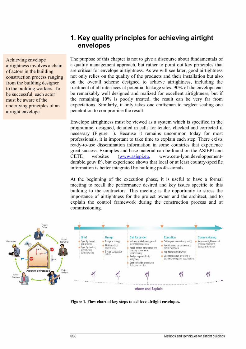
1. Key quality principles for achieving airtightenvelopes
The purpose of this chapter is not to give a discourse about fundamentals ofa quality management approach, but rather to point out key principles thatare critical for envelope airtightness. As we will see later, good airtightnessnot only relies on the quality of the products and their installation but alsoon the overall scheme designed to achieve airtightness, including thetreatment of all interfaces at potential leakage sites. 90% of the envelope canbe remarkably well designed and realized for excellent airtightness, but ifthe remaining 10% is poorly treated, the result can be very far fromexpectations. Similarly, it only takes one craftsman to neglect sealing onepenetration to compromise the result.
Envelope airtightness must be viewed as a system which is specified in theprogramme, designed, detailed in calls for tender, checked and corrected ifnecessary (Figure 1). Because it remains uncommon today for mostprofessionals, it is important to take time to explain each step. There existsready-to-use dissemination information in some countries that experiencegreat success. Examples and base material can be found on the ASIEPI andCETE websites (www.asiepi.eu, www.cete-lyon.developpement-durable.gouv.fr), but experience shows that local or at least country-specificinformation is better integrated by building professionals.
At the beginning of the execution phase, it is useful to have a formalmeeting to recall the performance desired and key issues specific to thisbuilding to the contractors. This meeting is the opportunity to stress theimportance of airtightness for the project owner and the architect, and toexplain the control framework during the construction process and atcommissioning.
Figure 1. Flow chart of key steps to achieve airtight envelopes.
Achieving envelopeairtightness involves a chainof actors in the buildingconstruction process rangingfrom the building designerto the building workers. Tobe successful, each actormust be aware of theunderlying principles of anairtight envelope.

Methods and techniques for airtight buildings 7/30
2. Airtightness design
2.1. Overall design principleThe fundamental principle for designing good airtightness is to think of it asa continuous and tight skin around the acclimatized volume (Figure 2). Inhorizontal and vertical section, the designer must be able to follow thisvirtual skin with a pencil, without lifting it. Each junction between buildingcomponents must be analysed to define the materials that will durablyensure airtightness at this location. When treating one given junction, thedesigner must keep in mind the continuity of the skin to the adjoining joints(Figure 3).
Note that the “skin” can take several forms: it can be plaster on a verticalwall, and then a vapour barrier for the roof, these two parts being boundwith an appropriate membrane for instance.
From an airtightness point of view, the “skin” can either be inside or outsideor both, however, it seems more commonly designed from the inside inpassive houses. Note that the use an external barrier to achieve airtightnessis a subject of research that is very promising regarding the envelopeleakage, but that needs to be further studied with regard to condensationdamage, a potential side effect being that the inside vapour barrier beneglected (Langmans et al, 2009). It has already been shown that thissolution was risky in cold climates regarding condensation (Geving et al.,2010). One conclusion of that study was that the outer barrier should haveno more than a tenth of the vapour resistance of the inner barrier.
Experience shows that construction details are often insufficiently preciseon the way sensible joints must be sealed, which is detrimental for tworeasons: first, it gives an inappropriate signal to the contractors andcraftsmen who do not feel the will of the architect to correctly treat thosejunctions; second, the craftsmen who are left alone have to improvise theirown solutions that can be inadequate. We recommend each junction to bedrawn at a scale of 1:5 to 1:10 approximately to clearly see how airtightnesswill be achieved.
Figure 2. Illustration of the principle of the airtight and continuous “skin”.
The designer must identifythe junctions that must besealed and specify adequatetightening products andmethods. The airtight andcontinuous “skin” method isstraightforward in principle.The designer should drawthe junctions at a scale of1:5 to 1:10 approximatelyfor a detailed description ofthe tightnening methods.

8/30 Methods and techniques for airtight buildings
Detail 01 (from figure 2)
Figure 3. Illustration of the continuity between several junctions.
2.2. Envelope penetrationsBecause each envelope penetration (e.g., for electricity supply) is a potentialleakage site, the general advice is to limit their number. For instance, thePassivhaus institute recommends a maximum of 15 penetrations.
The electrical network is often a source of irremediable problems. Oneeffective solution is to have only one penetration for the main electricitysupply to the electrical cabinet, and then to have the entire networkdistributed within the envelope (Figure 4). The problem is therefore reducedto sealing the penetration for the mains supply cable, which is quite simple.If this solution cannot be applied, the alternative is to seal each perforationwhich is extremely tedious. Several products are available on the market forthis specific application. Note however that if the electrical conduit allowsair to pass, the designer must see that this does not allow air to leak tooutside.
The same rule (i.e., one main penetration and a network distribution withinthe conditioned space) applies to water and gas supply lines.
Figure 4. Penetration for electricity supply.
Envelope penetrations maybe unavoidable, however,they should be minimizedand treated consistently withthe airtight “skin”.

Methods and techniques for airtight buildings 9/30
2.3. Common leakage sitesCommon leakage sites are identified in Figure 6 and in Figure 5. In Figure6, the sites are classified in 4 categories.
Figure 5. Vertical section of a typical building with identification of potential leakagejunctions.
1 Junction lower floor / vertical wall2 Junction window sill / vertical wall3 Junction window lintel / vertical wall4 Junction window reveal / vertical wall (horizontal view)5 Vertical wall (Cross section)6 Perforation vertical wall7 Junction top floor / vertical wall8 Penetration of top floor9 Junction French window / vertical wall10 Junction inclined roof / vertical wall11 Penetration inclined roof12 Junction inclined roof / roof ridge13 Junction inclined roof / window14 Junction rolling blind / vertical wall15 Junction intermediate floor / vertical wall16 Junction exterior door lintel / vertical wall17 Junction exterior door sill / sill18 Penetration lower floor / crawlspace or basement19 Junction service shaft / access door20 Junction internal wall / intermediate floor
It is useful for buildingprofessionals to be aware ofcommon leakage sites.These are listed andclassified in Figure 6 andFigure 5.

10/30 Methods and techniques for airtight buildings
Junctions between wallsand other walls or floors
Junctions between windowframes and walls
Electrical equipment
Access doors and other wallpenetrations
Figure 6. Common leakage sites classified in 4 categories.
2.4. Common trapsAside from the issues listed previously in this chapter, there are severaldetails that are known to be difficult to treat even with extreme care on site.We have listed those in this paragraph and included recommendations toovercome the problems raised.
Gypsum board ceilingIt is common to find gypsum board ceilings in residences or servicebuildings that are suspended with metal or plastic rods or spacers (Figure 7).Unless the rods are specifically designed for this, it should absolutely beavoided to perforate the vapour barrier with the rods: there are too many ofthem to ensure careful tightening around all rods.
The solutions below can be implemented:- The preferred solution is to staple the vapour barrier on the wood
frame if building design allows, and to screw the spacers on thewood frame. This way, the horizontal metal bars on which thegypsum boards are screwed can be attached to the spacers, leavingsome space for electrical conduits for instance (Figure 8) ;
- Another solution is to attach the horizontal metal bars to the metalsuspension rods, to glue the vapour barrier on the metal bars (e.g.with double-face tape) and then screw the boards on the metal bars.This solution proves to be effective with regard to airtightness buthas three disadvantages: first, if an airtightness test is performedduring the construction, it must be in pressurization mode to avoidpeeling the vapour film off the bars; second, it forbids any hole to be
Notoriously difficult designoptions for airtightnessshould be avoided.

Methods and techniques for airtight buildings 11/30
drilled in the ceiling; third, there is no space for electrical or otherconduits to run (Figure 9);
- Airtightness can also be achieved with a membrane perforated byspecifically designed suspension rods recently available on themarket.
Figure 7. Rods perforating the vapour barrier behind a gypsum board ceiling. Unlessthe rods are specifically designed for this, it is very difficult to achieve goodairtightness in this case.
Figure 8. Possible solution to achieve airtightness behind a gypsum board ceiling. Thevapour barrier is stapled directly on the wood frame.

12/30 Methods and techniques for airtight buildings
Figure 9. Possible solution to achieve airtightness behind a gypsum board ceiling. Thevapour barrier is glued on the metal bars.
Figure 10. Space left behind gypsum board to allow electrical cabling to pass withoutperforating the airtight layer. Courtesy Isover.

Methods and techniques for airtight buildings 13/30
Suspended ceilingsSuspended ceilings in service sector buildings are often made of tiles laid ona metal grid. On purpose, they can be lifted up to access the cavity wherepipes, wires and ductwork is installed. Supposedly airtight designs withvapour barrier and insulation layers directly behind the suspended ceilingsare bound to fail: by principle, the ceiling cannot be airtight as the tiles mustcome off easily; besides, there would be many perforations of the vapourbarrier (at each rod suspending the metal grid). An additional shortcomingof this design (if the insulation layer is directly on the tile) lies in the heatlosses through the ducts and pipes that run in an unconditioned space (Delpet al., 1998; Malmström et al., 2002).
In case of a suspended ceiling, the airtight barrier must be designed severaldecimetres away from the tiles. This allows the technical installations to belaid and maintained in the cavity without damaging the airtightness layer.
Floor joistsThe continuity of the “skin” is notoriously difficult to achieve with joistslaid on the vertical walls. Two common solutions are:
- To cut and tape the vapour barrier around each joist (Figure 11).This work requires patience and extreme care. The result is rarelyexcellent. In addition, it does not address the issue of vapourtransmission through the joist;
- To wrap around the joist a weather protect barrier before it isinstalled, and to tape the wrapping to the rest of the vapour barrier(Figure 11). This solution may be slightly easier to implement thanthe previous, but remains unsatisfactory.
Besides, both solutions do not address the thermal bridge problem at thisjunction. A better solution is to design the floor so that the joists do notpenetrate the vapour barrier. Figure 12 illustrates this option by hanging thejoists on hooks. This is a thermal-bridge- and leak- free design as theinsulation layer and vapour barrier are continuous. The designer shouldhowever check that provisions are made to solve noise and fire transmissionissues.

14/30 Methods and techniques for airtight buildings
Figure 11. Common problematic airtight designs for floor joists.
Figure 12. Thermal-bridge and leak- free design at floor joist.

Methods and techniques for airtight buildings 15/30
3. Important precautionsAirtightness is clearly an important aspect for low-energy buildings;however, it is sometimes not well understood that it is part of a buildingdesign whose interactions between various features can be complex. Toavoid problems, particular attention should be paid to: Liquid water management at the building level (water leakage
treatment, capillarity), which implies also some thinking at a largerscale (run-off water);
Provision for air renewal, which means that a natural, mechanical orhybrid ventilation system must be designed to extract indoorpollutants (including water vapour and flue gases if applicable) andthat it must be compatible with the airtightness sought.
3.1. Run-off waterThe designer should take measures to avoid run-off water to accumulatenear the building facades. This requires to have a global view on thedrainage of storm water at the neighbourhood scale and to define a strategyfor the lot of interest. Appropriate slopes should allow surface water to beevacuated from the immediate surrounding of the facades, and thereby limitwater capillarity issues or water leaks. This can be the opportunity makeprovision for storage in a water tank or pond away from the building (Figure13).
Figure 13. Example of a strategy implemented to keep run-off water away from abuilding.
Liquid water managementand provision for airrenewal are two key issuesassociated with envelopeairtightness. The designermust carefully address thoseissues and take measures toavoid building damage ordegraded indoor air quality.
Run-off water should bedriven away from thebuilding facades withappropriate slopes anddrainage strategy.

16/30 Methods and techniques for airtight buildings
3.2. Water leaks from walls and roofWhile it is in general essential to avoid water leaks in the envelope, itbecomes even more crucial with an airtight building as it will be harder forthe water to escape. In case of renovation, a pre-requisite is to performcareful repairs of water leaks to obtain a perfectly watertight envelope.Where applicable, a rain screen can be useful for additional safety in case oftile failure, as well as to preserve the thermal resistance of the insulationlayer which can be downgraded due to wind infiltration (Figure 15-Figure14).
Figure 14. Schematicrepresentation of watertightenvelope.
Figure 15. Installation of a rain screen.Courtesy Knauf Insulation.
The designer should takemeasures to avoid (andrepair if applicable) waterinfiltration from throughwalls and roof.

Methods and techniques for airtight buildings 17/30
3.3. CapillarityWater can enter the envelope by capillarity, i.e., the ability for water tomove up through porous building materials. Generally, this issue is notcrucial in new constructions given their foundations and installation ofcapillary breaks. Design options for new buildings are well-documented.This problem is however essential in old buildings and aggravated with theabsence of foundations and porous structures. To overcome this problem,the following actions can be envisaged:
- install a drainage system around the building. It will typically beabout 1 m away from the façade to avoid weakening the structure,especially in the absence of foundation; and/or
- underpin the building and install a water barrier. This solution issimilar to what is installed in new constructions, however, extremecare must be taken to avoid the collapse of the façade. This work isusually performed by portions.
Figure 16. Water barrier.
Figure 17. Drainage system. Courtesy Wienerberger.
While capillarity issues aregenerally well-documentedand treated in newbuildings, they areparticularly important toaddress in buildingrenovation.
18/30 Methods and techniques for airtight buildings
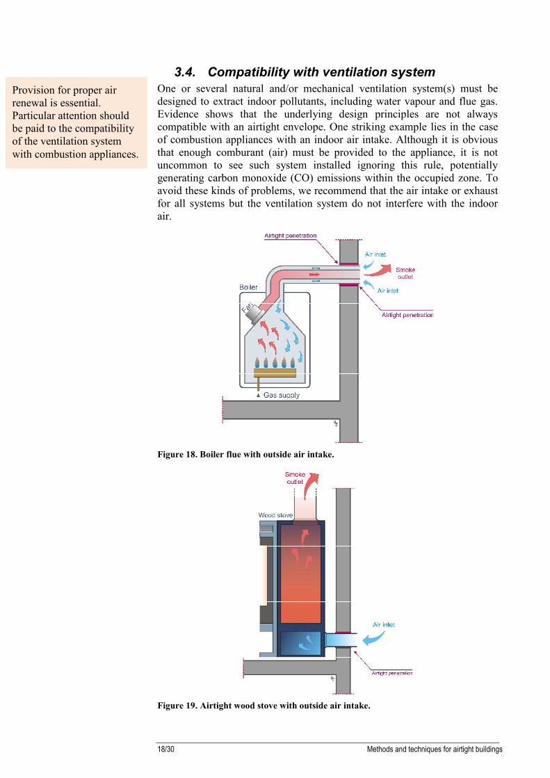
3.4. Compatibility with ventilation systemOne or several natural and/or mechanical ventilation system(s) must bedesigned to extract indoor pollutants, including water vapour and flue gas.Evidence shows that the underlying design principles are not alwayscompatible with an airtight envelope. One striking example lies in the caseof combustion appliances with an indoor air intake. Although it is obviousthat enough comburant (air) must be provided to the appliance, it is notuncommon to see such system installed ignoring this rule, potentiallygenerating carbon monoxide (CO) emissions within the occupied zone. Toavoid these kinds of problems, we recommend that the air intake or exhaustfor all systems but the ventilation system do not interfere with the indoorair.
Figure 18. Boiler flue with outside air intake.
Figure 19. Airtight wood stove with outside air intake.
Provision for proper airrenewal is essential.Particular attention shouldbe paid to the compatibilityof the ventilation systemwith combustion appliances.

Methods and techniques for airtight buildings 19/30
4. Tightening products
The approach to design and install a continuous airtight layer systemdepends on the construction types; however, it is possible to define twocommon major steps: The treatment of opaque walls; The treatment of joints between building components and walls.
The designer should choose the appropriate tightening materials based ontheir specifications in terms of product compatibility, vapour diffusionproperties, etc. Today, there is little information on the durability of theseproducts, although there exist recent studies on this subject (Gross andMaas, 2011).
Timber-frame structure Brick structure
Treatment of opaquewalls
Treatment of joints between buildingcomponents and walls
Figure 20. Distinction between the treatment of walls and joints between buildingcomponents and walls.
In this paper, the productsare described in generalterms, although there maybe large differences betweenthe physical characteristicsof products falling under thesame generic term (e.g.vapour barrier, siliconemastic, etc.).Designers and installersshould check on a case-by-case basis the compatibilityof the products for theirspecific use.

20/30 Methods and techniques for airtight buildings
4.1. Treatment of opaque wallsThe treatment of opaque walls consist in tightening large surfaces that areleaky either because they are porous or because they include a large numberof discontinuities. There are two major ways to tighten these surfaces: Plasters are generally used for the heavy constructions made of
masonry blocks in external insulation systems or low-U masonryblocks;
Vapour barriers or retarders are dominantly used for dryconstructions (e.g., timber-frame constructions) or internal insulationsystems.
PlastersPlasters are fluid or paste-like mixtures made of cement, lime, or gypsum.These products are spread or projected on the surface. The choice of theplaster should be based on: The hygrothermal behaviour of the finished wall, including the
plaster and possibly additional coverings; The nature of the surface, in particular its compatibility with the
plaster and surface grime; The location of the surface (e.g., whether it is exposed to rain or
bumps); The methods and conditions for on-site implementation; The type of finish desired; The possible additional coverings.
Figure 21. Plaster applied on interior wall.
The solution chosen for thetreatment of the opaquewalls is a first crucial stepbecause it dictates thelocation of the weak pointsat joints that have to betreated. It represents themajor part of the “airtightskin”.
Methods and techniques for airtight buildings 21/30
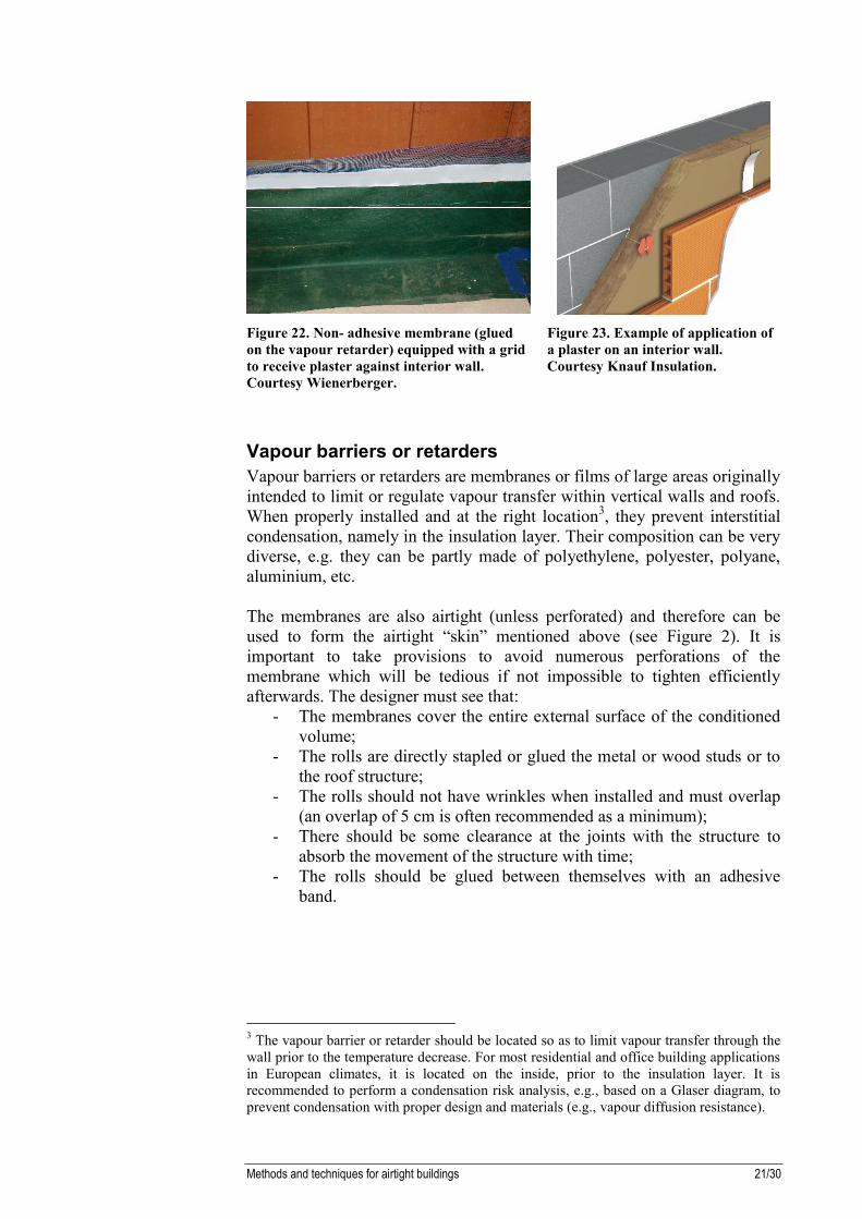
Figure 22. Non- adhesive membrane (gluedon the vapour retarder) equipped with a gridto receive plaster against interior wall.Courtesy Wienerberger.
Figure 23. Example of application ofa plaster on an interior wall.Courtesy Knauf Insulation.
Vapour barriers or retardersVapour barriers or retarders are membranes or films of large areas originallyintended to limit or regulate vapour transfer within vertical walls and roofs.When properly installed and at the right location3, they prevent interstitialcondensation, namely in the insulation layer. Their composition can be verydiverse, e.g. they can be partly made of polyethylene, polyester, polyane,aluminium, etc.
The membranes are also airtight (unless perforated) and therefore can beused to form the airtight “skin” mentioned above (see Figure 2). It isimportant to take provisions to avoid numerous perforations of themembrane which will be tedious if not impossible to tighten efficientlyafterwards. The designer must see that:
- The membranes cover the entire external surface of the conditionedvolume;
- The rolls are directly stapled or glued the metal or wood studs or tothe roof structure;
- The rolls should not have wrinkles when installed and must overlap(an overlap of 5 cm is often recommended as a minimum);
- There should be some clearance at the joints with the structure toabsorb the movement of the structure with time;
- The rolls should be glued between themselves with an adhesiveband.
3 The vapour barrier or retarder should be located so as to limit vapour transfer through thewall prior to the temperature decrease. For most residential and office building applicationsin European climates, it is located on the inside, prior to the insulation layer. It isrecommended to perform a condensation risk analysis, e.g., based on a Glaser diagram, toprevent condensation with proper design and materials (e.g., vapour diffusion resistance).

22/30 Methods and techniques for airtight buildings
4.2. Treatment of joints between opaque walls andother building components
Each joint between the opaque walls and the other building components hasto be tightened. This includes joints with other opaque walls, windows,building structure components (e.g., beam, floor joist), doors, ducts (e.g., fora ventilation system, an exhaust hood, or a combustion appliance), pipes,electrical conduits or cables.
The designers and workers must keep in mind the principle of continuity ofthe airtight skin at these joints.
Pre-compressed impregnated foamsThe products that are used are polyurethane or polyester foams impregnatedwith a synthetic butyl or acrylic resin.
The foams are presented as rolls a few centimetres wide. Their thickness isreduced when rolled-up, but they get thicker more or less rapidly as they areinstalled. The retarded decompression process allows the gaps to be fillednicely while the foam was put without force into them. It is particularlyuseful for window installers when the windows are placed within the wallstructure as the window can be adjusted before decompression occurs. Thisalso prevents the foam from sliding and rolling while it is placed within thewall structured.
Joints between opaque wallsand other buildingcomponents are generallysealed with either:- pre-compressed
impregnated foams;- adhesive membranes and
tapes;- extruded mastics;- closed-cell expanding
foams; or- specific sealing products.
One common requirementfor these products is thatthey must be flexibleenough to absorb buildingstress without cracking.

Methods and techniques for airtight buildings 23/30
Figure 24. Pre-compressed foam. It gets thicker slowly when unrolled to allow theworker to put it in place and adjust the window before the full decompression occurs.Courtesy Tremco illbruck.
Figure 25. Multi-functional pre-compressed foam. Its size and design prevents air andwater infiltration on both sides of the window or door as well as thermal insulation.Courtesy Tremco illbruck.

24/30 Methods and techniques for airtight buildings
Adhesive membranes and tapesAdhesives membranes seal joints between the peripheral of a window and avapour barrier or retarder or a plaster.
These membranes are flexible. They generally consist of a polyethylene filmassociated with a nonwoven fabric with:
- on one side, an adhesive tape, single or double-face, that is glued tosmooth surfaces (wood, aluminium, PVC). If the membrane is notequipped with an adhesive tape, the installer can use an extrudedmastic;
- on the other side:o either an adhesive tape (e.g., butyl-based to adhere on porous
surfaces such as concrete or masonry blocks); oro a polyester or fibre glass grid that can be covered with a
plaster.
Figure 26. Application of a membrane around a window. Courtesy Soudal
Adhesive tapes seal junctions between similar building elements. They areoften used in three cases:
- To seal Orientated Strained Boards (OSB) or other wood panels intimber-frame constructions;
- To glue two adjacent rolls of vapour barrier or retarder;- To seal a film on a non-mineral smooth surface (wood elements and
panels, PVC) or a smooth metal surface.
Depending on the application, the tapes can be rigid or flexible. They aremade of a paper or nonwoven textile (polyethylene or polypropylene)support. The surface where the tape is glued must be clean, dry, grease- andsolvent-free for a good adhesion. A primer can be used in some cases toincrease adhesion.

Methods and techniques for airtight buildings 25/30
Figure 27. Use of a tape on a vapour barrier. Courtesy Knauf Insulation.
Figure 28. Plasto-elastic butyl rubber adhesive / sealant applied to one side of analuminised polyester film. Courtesy Tremco illbruck.
Extruded masticsThese products can fill small gaps (about 10 mm maximum). They aregenerally packaged in cartridges that can be used in a regular caulking gun.
There exits a wide range of mastics based on “hybrid”, polyurethane (PU),silicone, butyl or acrylic. Acrylic-based mastics should be used for interioruse and finishing only, while other mastics can be used outdoors with someprecautions. Butyl mastics provide excellent adhesion to most surfaces buthave limited elasticity and are solvent-based. Most silicone mastics provideexcellent airtightness with glass and metal and are UV-resistant, while PUmastics adhere very well to most surfaces, but are more UV-sensitive thansilicone. Paint can be applied on PU mastics, which can help protect thejoints. “Hybrid” sealants4 are claimed to combine the strength ofpolyurethanes with the weathering resistance of silicones.
4 The terminology used for these sealants is confuse. They are sometimes referred to asSilyl Modified Polymers (SMP) or MS polymers for instance.

26/30 Methods and techniques for airtight buildings
ISO 11600 proposes a classification for glass (G) and construction (F,standing for “façade”) sealants based on end-use (F or G), movementcapability, elasticity, and modulus for an appropriate choice depending onthe application (BASA, 1999).
Mastics alone should not be used to fill large deep gaps. For this, a back-upmaterial (or backer rod) can be installed simply to limit the depth that has tobe filled with the mastic. Generally, it has a square or circular section and ismade of polyethylene closed- or open-cell foams.
The use of a backer rod is also recommended:- to provide a backing against which the sealant is applied, forcing thesealant to the sides of the joint;- to prevent 3-sided bonding (which would be detrimental to the jointfunctioning and longevity) since the mastic does not adhere to the backerrod.
Figure 29. Closed-cell PE round backer rod. Courtesy Soudal.
Figure 30. Application of sealant with caulking gun. Courtesy Knauf insulation.

Methods and techniques for airtight buildings 27/30
Expanding foamsExpanding foams recommended for airtightening are generally elastic PU-foams. Elasticity is an important requirement for these foams so that thejunction remains airtight with time. Rigid foams will crack as the buildingstructure ages. Dry foam should not be cut to avoid deterioration of itsairtightness properties and stability.
In air sealing applications, these foams are used primarily at the junctionbetween the windows and the walls.
Figure 31. Application of elastic PU foam around a window. Courtesy Soudal.
Specific sealing productsIn addition to the materials and products listed above, there are products forvery specific applications. These include:
Pipe, duct or cable rubber grommetsThese products allow one to create an airtight seal around circular-sectionelements such as plumbing pipes, electrical conduits or cables as these passthrough the airtight layer.
There exists an array of products for diameters ranging from a fewmillimetres up to 355 mm.
Figure 32. Self adhesive membrane grommet. For sealing building components whichpenetrate the roof or wall construction and/or the vapour barrier. Courtesy Lindab.
28/30 Methods and techniques for airtight buildings
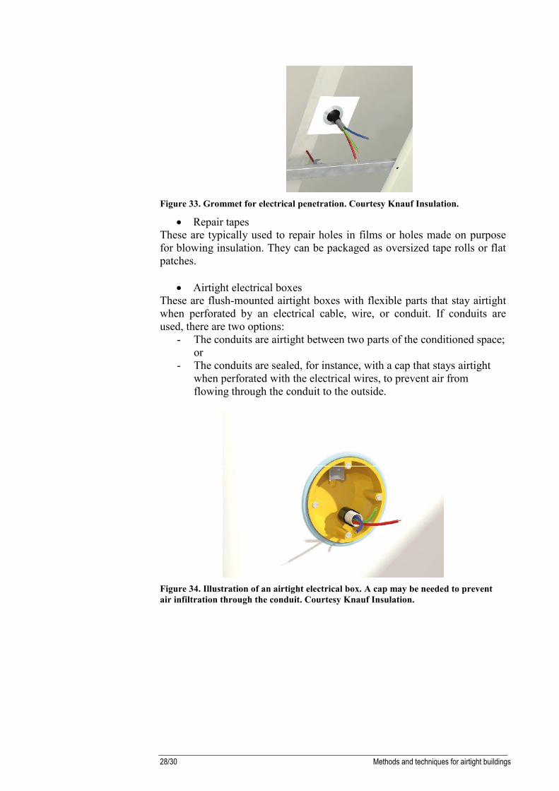
Figure 33. Grommet for electrical penetration. Courtesy Knauf Insulation.
Repair tapesThese are typically used to repair holes in films or holes made on purposefor blowing insulation. They can be packaged as oversized tape rolls or flatpatches.
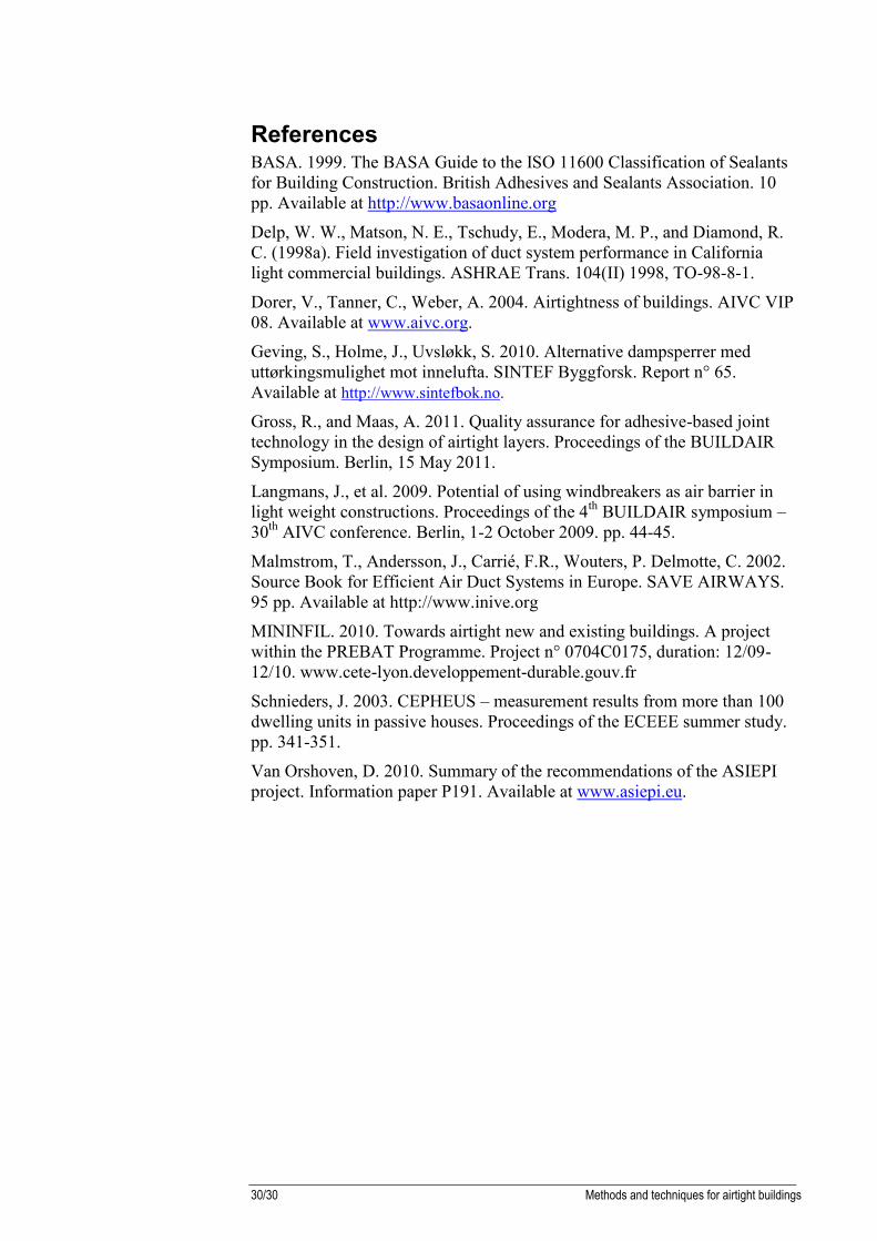
Airtight electrical boxesThese are flush-mounted airtight boxes with flexible parts that stay airtightwhen perforated by an electrical cable, wire, or conduit. If conduits areused, there are two options:
- The conduits are airtight between two parts of the conditioned space;or
- The conduits are sealed, for instance, with a cap that stays airtightwhen perforated with the electrical wires, to prevent air fromflowing through the conduit to the outside.
Figure 34. Illustration of an airtight electrical box. A cap may be needed to preventair infiltration through the conduit. Courtesy Knauf Insulation.

Methods and techniques for airtight buildings 29/30
ConclusionEnvelope airtightness clearly represents a major challenge towards thegeneralization of nearly zero-energy buildings in new constructions andrenovation. There are many technical and organizational issues to deal with,and todays’ observations and field campaigns suggest that there issignificant room for improvement to overcome these challenges.
The good news is that there are methods and products readily available tobuild airtight. There are both:
- Solutions that have proved to be very effective for a number of yearsalready (about 20 for some), in particular in pioneering very low-energy buildings projects; and
- Fairly new approaches and technical solutions emerging thanks tothe considerable RTD efforts of research bodies, technical centresand industries.
Especially with the latter, there are many areas that merit furtherinvestigation, for instance with regard to cost and durability,ventilation/infiltration/indoor air quality interactions.
One major barrier resides in the opposition between on the one hand theprofound changes that are needed to build airtight in the design options andsolutions implementation of nearly all building workers; on the other hand,the weight of tradition in the building sector. Therefore, we expect that themarket transformation towards airtight buildings in any country willing toimplement a wide-scale policy on this issue will be a long process, althoughthe market uptake of labels such as PassivHaus, Minergie-P or Effinergiefor instance in some regions brings optimism. Good training anddissemination are two important keys to achieve this goal.
30/30 Methods and techniques for airtight buildings
ReferencesBASA. 1999. The BASA Guide to the ISO 11600 Classification of Sealantsfor Building Construction. British Adhesives and Sealants Association. 10pp. Available at http://www.basaonline.org
Delp, W. W., Matson, N. E., Tschudy, E., Modera, M. P., and Diamond, R.C. (1998a). Field investigation of duct system performance in Californialight commercial buildings. ASHRAE Trans. 104(II) 1998, TO-98-8-1.
Dorer, V., Tanner, C., Weber, A. 2004. Airtightness of buildings. AIVC VIP08. Available at www.aivc.org.
Geving, S., Holme, J., Uvsløkk, S. 2010. Alternative dampsperrer meduttørkingsmulighet mot innelufta. SINTEF Byggforsk. Report n° 65.Available at http://www.sintefbok.no.
Gross, R., and Maas, A. 2011. Quality assurance for adhesive-based jointtechnology in the design of airtight layers. Proceedings of the BUILDAIRSymposium. Berlin, 15 May 2011.
Langmans, J., et al. 2009. Potential of using windbreakers as air barrier inlight weight constructions. Proceedings of the 4th BUILDAIR symposium –30th AIVC conference. Berlin, 1-2 October 2009. pp. 44-45.
Malmstrom, T., Andersson, J., Carrié, F.R., Wouters, P. Delmotte, C. 2002.Source Book for Efficient Air Duct Systems in Europe. SAVE AIRWAYS.95 pp. Available at http://www.inive.org
MININFIL. 2010. Towards airtight new and existing buildings. A projectwithin the PREBAT Programme. Project n° 0704C0175, duration: 12/09-12/10. www.cete-lyon.developpement-durable.gouv.fr
Schnieders, J. 2003. CEPHEUS – measurement results from more than 100dwelling units in passive houses. Proceedings of the ECEEE summer study.pp. 341-351.
Van Orshoven, D. 2010. Summary of the recommendations of the ASIEPIproject. Information paper P191. Available at www.asiepi.eu.


The Air Infiltration and Ventilation Centre was inaugurated through the International Energy Agencyand is funded by the following countries:
Belgium, Czech Republic, Denmark, France, Germany, Greece, Italy, Japan, Republic of Korea,Netherlands, New Zealand, Norway, Sweden, and United States of America.
The Centre provides technical support in air infiltration and ventilation research and application. Theaim is to provide an understanding of the complex behaviour of the air flow in buildings and toadvance the effective application of associated energy saving measures in both the design of newbuildings and the improvement of the existing building stock.
Air Infiltration and Ventilation CentreOperating Agent and ManagementINIVE EEIGLozenberg 7B-1932 Sint-Stevens-WoluweBelgium
www.aivc.orgTel: +32 2 655 77 11
Fax: +32 2 653 07 [email protected]