Embed Size (px)
Citation preview
Methodology for ablationinvestigations in the VKI Plasmatron
facility: Preliminary results with acarbon fiber preform
5th Ablation Workshop, Lexington (KY), Februrary 27th - March 01st 2012
Bernd Helber1,2, Olivier Chazot1, Annick Hubin2 and Thierry Magin1
1
Aeronautics and Aerospace Department, von Karman Institute for Fluid Dynamics, Belgium
2
Department of Electrochemical and Surface Engineering, Vrije Universiteit Brussel

Introduction Ground testing Numerical tools Preliminary results Conclusions & perspective
Outline
1 Introduction
2 Ground testing in Plasmatron facility
3 Numerical tools development
4 Results with a carbon fiber preform (preliminary)
5 Conclusions and perspective
von Karman Institute for Fluid Dynamics / Vrije Universiteit Brussel 2 / 31

Introduction Ground testing Numerical tools Preliminary results Conclusions & perspective
Outline
1 IntroductionBackgroundOverview of ablation test campaigns at VKIResearch goals
2 Ground testing in Plasmatron facility
3 Numerical tools development
4 Results with a carbon fiber preform (preliminary)
5 Conclusions and perspective
von Karman Institute for Fluid Dynamics / Vrije Universiteit Brussel 3 / 31
Introduction Ground testing Numerical tools Preliminary results Conclusions & perspective
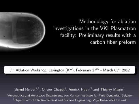
Background: VKI
Ablation investigations for high enthalpy plasma flows andhypersonic applications
2
EXPERIMENTAL DATA
PHYSICO-CHEMICAL MODELS
COMPUTATIONALMETHODS
Basic ingredients for prediction in aerospace science
von Karman Institute for Fluid Dynamics / Vrije Universiteit Brussel 4 / 31
Introduction Ground testing Numerical tools Preliminary results Conclusions & perspective
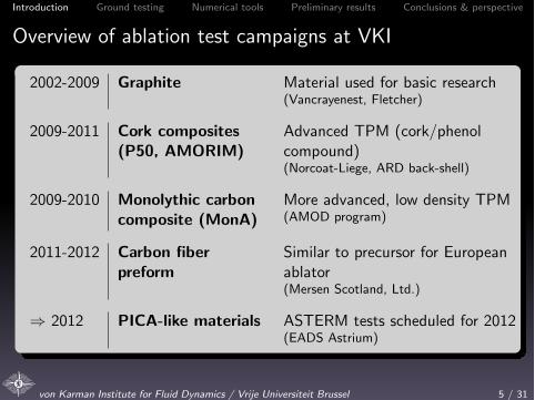
Overview of ablation test campaigns at VKI
2002-2009 Graphite Material used for basic research(Vancrayenest, Fletcher)
2009-2011 Cork composites(P50, AMORIM)
Advanced TPM (cork/phenolcompound)(Norcoat-Liege, ARD back-shell)
2009-2010 Monolythic carboncomposite (MonA)
More advanced, low density TPM(AMOD program)
2011-2012 Carbon fiberpreform
Similar to precursor for Europeanablator(Mersen Scotland, Ltd.)
) 2012 PICA-like materials ASTERM tests scheduled for 2012(EADS Astrium)
von Karman Institute for Fluid Dynamics / Vrije Universiteit Brussel 5 / 31

Introduction Ground testing Numerical tools Preliminary results Conclusions & perspective
Research goals
Definition of a methodology to characterizematerial response and gas-gas / gas-surface interactionof innovative ablators in the VKI Plasmatron facility
Ablation modelling framework for development ofmaterial response models for carbon / resin composites
and coupling with in-house codes
Model validation
Flight extrapolation
von Karman Institute for Fluid Dynamics / Vrije Universiteit Brussel 6 / 31

Introduction Ground testing Numerical tools Preliminary results Conclusions & perspective
Outline
1 Introduction
2 Ground testing in Plasmatron facilityPlasmatron facilityRecession AnalysisEmission Spectroscopy
3 Numerical tools development
4 Results with a carbon fiber preform (preliminary)
5 Conclusions and perspective
von Karman Institute for Fluid Dynamics / Vrije Universiteit Brussel 7 / 31

Introduction Ground testing Numerical tools Preliminary results Conclusions & perspective
High-enthalpy tests combined with multiscalecharacterization
von Karman Institute:Analysis in High-Enthalpy PlasmaFlows
Vrije Universiteit Brussel:Multiscale Characterization(SEM, EDX, XPS, AES)
10μm
von Karman Institute for Fluid Dynamics / Vrije Universiteit Brussel 8 / 31

Introduction Ground testing Numerical tools Preliminary results Conclusions & perspective
Plasmatron facility
1.2 MW Inductively Coupled Plasmatron (ICP)pressure probe
heat flux probe + protective O-ring + holder protection (cork)
optical access radiometer
spectrometer optics
high speed camera
ablative sample
plasma jet exit
optical access pyrometer
sample holder +protection (cork)
Plasmatron test chamber showing experimental setup and torch exit
Gas: Air, N2
, CO2
, Ar
Power: 1.2 MW
Heat-flux: 90 kW/m2 - 10 MW/m2
Pressure: 10 mbar - 600 mbar
von Karman Institute for Fluid Dynamics / Vrije Universiteit Brussel 9 / 31

Introduction Ground testing Numerical tools Preliminary results Conclusions & perspective
Measurement techniques development
windows'
'test'sample'
plasma'torch'
light'collec2on'system'(lens'&'mirrors)''
exhaust'&'''''heat'exchanger''
reac2ve'boundary'''''layer'
op2cal'fibre'ends'
High'speed'camera'
test'chamber'
HR>4000'spectrometer'
2>color'pyrometer'Radiometrysurface temperatures &emissivity
ThermocouplesInternal temperature histories
High-speed-camerain-situ recession and gas-phaseanalysis
Optical emissionspectroscopytemporally and spatiallyresolved boundary layerchemistry
(future: recession sensors)
von Karman Institute for Fluid Dynamics / Vrije Universiteit Brussel 10 / 31
Introduction Ground testing Numerical tools Preliminary results Conclusions & perspective
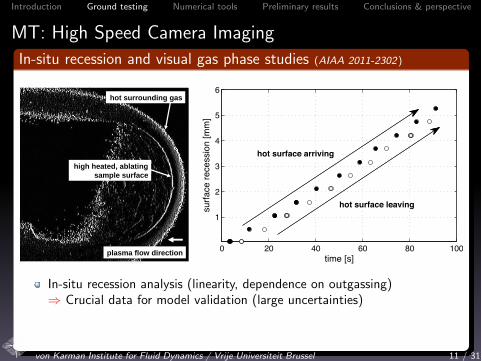
MT: High Speed Camera ImagingIn-situ recession and visual gas phase studies (AIAA 2011-2302)
Test start Test end
high heated, ablating
sample surface
hot surrounding gas
plasma flow direction0 20 40 60 80 100
1
2
3
4
5
6
time [s]
surfa
ce re
cess
ion
[mm
]
hot surface arriving
hot surface leaving
hot surface arriving
hot surface leaving
In-situ recession analysis (linearity, dependence on outgassing)) Crucial data for model validation (large uncertainties)
Gas phase observation (o↵-set of surrounding flame)
) Outgassing e↵ects
von Karman Institute for Fluid Dynamics / Vrije Universiteit Brussel 11 / 31
Introduction Ground testing Numerical tools Preliminary results Conclusions & perspective
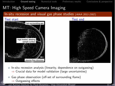
MT: High Speed Camera ImagingIn-situ recession and visual gas phase studies (AIAA 2011-2302)
Test start Test end
high heated, ablating
sample surface
hot surrounding gas
plasma flow direction
In-situ recession analysis (linearity, dependence on outgassing)) Crucial data for model validation (large uncertainties)
Gas phase observation (o↵-set of surrounding flame)) Outgassing e↵ects
von Karman Institute for Fluid Dynamics / Vrije Universiteit Brussel 11 / 31

Introduction Ground testing Numerical tools Preliminary results Conclusions & perspective
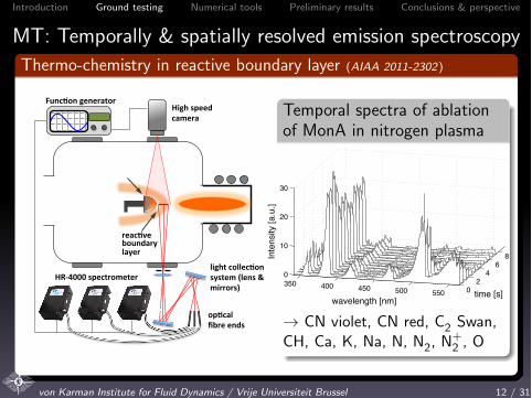
MT: Temporally & spatially resolved emission spectroscopy
Thermo-chemistry in reactive boundary layer
(AIAA 2011-2302)
light&collec*on&system&(lens&&&mirrors)&&
reac*ve&boundary&&&&&layer&
op*cal&fibre&ends&
High&speed&camera&
HR<4000&spectrometer&
Func*on&generator&3 spectrometers with broadwavelength range per acquisition(200� 1000 nm)) temporal resolution (up to 5 ms)
imaging mode with opticalmagnification factor of ⇠ 2) narrow boundary layer screening (allspectrometers within ⇠ 3mm)
Function generator to triggeracquisition with high-speed-camera) temporally resolved distance ofprobing volumes from ablating surface
von Karman Institute for Fluid Dynamics / Vrije Universiteit Brussel 12 / 31
Introduction Ground testing Numerical tools Preliminary results Conclusions & perspective
MT: Temporally & spatially resolved emission spectroscopyThermo-chemistry in reactive boundary layer (AIAA 2011-2302)
light&collec*on&system&(lens&&&mirrors)&&
reac*ve&boundary&&&&&layer&
op*cal&fibre&ends&
High&speed&camera&
HR<4000&spectrometer&
Func*on&generator&Temporal spectra of ablationof MonA in nitrogen plasma
02
46
8
350 400 450 500 550
0
10
20
30
time [s]wavelength [nm]
Inte
nsity
[a.u
.]
! CN violet, CN red, C2
Swan,CH, Ca, K, Na, N, N
2
, N+
2
, O
von Karman Institute for Fluid Dynamics / Vrije Universiteit Brussel 12 / 31
Introduction Ground testing Numerical tools Preliminary results Conclusions & perspective
Outline
1 Introduction
2 Ground testing in Plasmatron facility
3 Numerical tools development
4 Results with a carbon fiber preform (preliminary)
5 Conclusions and perspective
von Karman Institute for Fluid Dynamics / Vrije Universiteit Brussel 13 / 31
Introduction Ground testing Numerical tools Preliminary results Conclusions & perspective
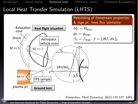
Local Heat Transfer Simulation (LHTS)
M">>"1"
Shock"
Relaxa/on"zone"
Aerospace"vehicle"nose"
M << 1
Real%flight%situa-on%
Ground%test%
y"Body"
x"
δ"
Ve"
(dU/dx)e"
M"<<"1"
plasma"jet"
TPS"sample"
Rebuilding of freestream properties& stgn.pt. heat flux similarity:
Hf = Hexp,pf = pexp,�f = �exp, � = (dU/dx)e
Kolesnikov, Fluid Dynamics, 28(1):131-137, 1993.
von Karman Institute for Fluid Dynamics / Vrije Universiteit Brussel 14 / 31

Introduction Ground testing Numerical tools Preliminary results Conclusions & perspective
Combined numerical/experimental rebuilding procedure
M"<<"1"TPS"sample"
Ground'test'measurements'Navier0Stokes0domain'EM0field'
domain'
Coupled'domain' Boundary'layer'parameter'
VKI'ICP'code'(LTE'assumpCon)'
qw,'Tw,'ps,'pd'
Boundary layer solver
Input: Boundary layer parameter (LTE CFD computation) &measurements from experiments
Procedure: Iteration on boundary layer edge temperature Te :) qnw = q
(exp)w = qw (�,Tw , pe , he ,�, ...)
Output: Edge enthalpy He , boundary layer chemistry, (catalycity)
von Karman Institute for Fluid Dynamics / Vrije Universiteit Brussel 15 / 31
Introduction Ground testing Numerical tools Preliminary results Conclusions & perspective
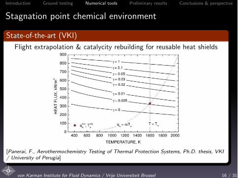
Stagnation point chemical environment
State-of-the-art (VKI)
Flight extrapolation & catalycity rebuilding for reusable heat shields
[Panerai, F., Aerothermochemistry Testing of Thermal Protection Systems, Ph.D. thesis, VKI/ University of Perugia]
von Karman Institute for Fluid Dynamics / Vrije Universiteit Brussel 16 / 31

Introduction Ground testing Numerical tools Preliminary results Conclusions & perspective
Stagnation point chemical environment
Extension to ablationGSI models for CFD codes:Control volume approach for B’-tablegeneration (MUTATION)
Pyrolysis gases B’gChar flux B’c
Mass transfer flux Advection flux
Flow field
Control Volume
Assumptions:
Chemically active surface:! carbon char reacts withoxygen
Chemically active species from! pyrolysis of decomposingmaterial! edge of boundary layer(equilibrium chemistry)
Collaboration J. de Muelenaere (VKI),J. Lachaud & N.N. Mansour (NASA Ames) (AIAA 2011-3616)
von Karman Institute for Fluid Dynamics / Vrije Universiteit Brussel 17 / 31

Introduction Ground testing Numerical tools Preliminary results Conclusions & perspective
Stagnation point chemical environmentExtension to ablation
GSI models for CFD codes:Control volume approach for B’-tablegeneration (MUTATION)
Pyrolysis gases B’gChar flux B’c
Mass transfer flux Advection flux
Flow field
Control Volume 1000 2000 3000 4000Temperature [K]
0.001
0.01
0.1
1
10
100
1000
B’c
B’g = 10
2.510.10.050.010.0010.00001
) Coupling with stagnation lineformulation
) Development of a new approachto build B’-tables
Collaboration J. de Muelenaere (VKI),J. Lachaud & N.N. Mansour (NASA Ames) (AIAA 2011-3616)
von Karman Institute for Fluid Dynamics / Vrije Universiteit Brussel 17 / 31
Introduction Ground testing Numerical tools Preliminary results Conclusions & perspective
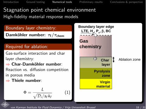
Stagnation point chemical environmentHigh-fidelity material response models
Boundary layer chemistry:
Damkohler number: ⌧f/⌧chem
Required for ablation:
Gas-surface interaction and charlayer chemistry:) Char-Damkohler number:Reaction vs. di↵usion competitionin porous media) Thiele number:
� =Lp
Di/sf kf(1)
Char
layer
Pyrolysis
zone
Virgin
material
Boundary layer edge
LTE, He, P
e, ‚, BC
Gas
chemistry
Ablation zone
! Experiments with microscalecharacterization
von Karman Institute for Fluid Dynamics / Vrije Universiteit Brussel 18 / 31

Introduction Ground testing Numerical tools Preliminary results Conclusions & perspective
Stagnation point chemical environmentHigh-fidelity material response models
Boundary layer chemistry:
Damkohler number: ⌧f/⌧chem
Required for ablation:
Gas-surface interaction and charlayer chemistry:) Char-Damkohler number:Reaction vs. di↵usion competitionin porous media) Thiele number:
� =Lp
Di/sf kf(1)
Char
layer
Pyrolysis
zone
Virgin
material
Boundary layer edge
LTE, He, P
e, ‚, BC
Gas
chemistry
Ablation zone
estimation of
the effective
reactive
surface area
not available
! Experiments with microscalecharacterization
von Karman Institute for Fluid Dynamics / Vrije Universiteit Brussel 18 / 31

Introduction Ground testing Numerical tools Preliminary results Conclusions & perspective
Outline
1 Introduction
2 Ground testing in Plasmatron facility
3 Numerical tools development
4 Results with a carbon fiber preform (preliminary)Plasma tests of carbon fiber preformScanning Electron Microscopy
5 Conclusions and perspective
von Karman Institute for Fluid Dynamics / Vrije Universiteit Brussel 19 / 31

Introduction Ground testing Numerical tools Preliminary results Conclusions & perspective
Plasma tests of carbon fiber preform
Carbon fiber preform, Mersen Scotland Ltd.
Chopped carbon fibers inphenol-resin slury, fullycarbonized (1200K)
density: 180� 210 kg/m3
specific surface area: 18m2/g(fiber volume surface:3.24E6 m2/m3)
2D randomly oriented carbonfibers, through-the-thickness(TTT) direction parallel toflow field in this study
similar to precursor forEuropean ablator ASTERM
von Karman Institute for Fluid Dynamics / Vrije Universiteit Brussel 20 / 31
Introduction Ground testing Numerical tools Preliminary results Conclusions & perspective
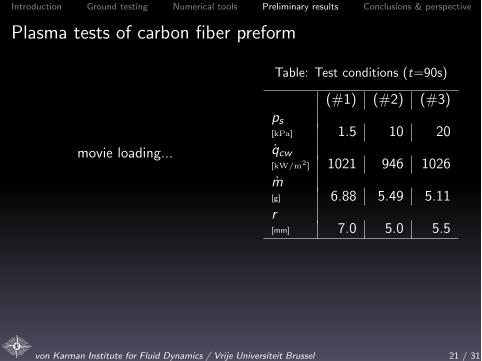
Plasma tests of carbon fiber preform
movie loading...
Table: Test conditions (t=90s)
(#1) (#2) (#3)ps[kPa] 1.5 10 20qcw[kW/m2
] 1021 946 1026m[g] 6.88 5.49 5.11r[mm] 7.0 5.0 5.5
! strongest degradation at lowest static pressure) di↵usion mechanisms in di↵usion limited regime (TS > 2000K )?) other failure modes (Spallation?)
von Karman Institute for Fluid Dynamics / Vrije Universiteit Brussel 21 / 31

Introduction Ground testing Numerical tools Preliminary results Conclusions & perspective
Plasma tests of carbon fiber preform
movie loading...
Table: Test conditions (t=90s)
(#1) (#2) (#3)ps[kPa] 1.5 10 20qcw[kW/m2
] 1021 946 1026
m[g] 6.88 5.49 5.11r[mm] 7.0 5.0 5.5
! strongest degradation at lowest static pressure) di↵usion mechanisms in di↵usion limited regime (TS > 2000K )?) other failure modes (Spallation?)
von Karman Institute for Fluid Dynamics / Vrije Universiteit Brussel 21 / 31
Introduction Ground testing Numerical tools Preliminary results Conclusions & perspective
Plasma tests of carbon fiber preform
movie loading...
Table: Test conditions (t=90s)
(#1) (#2) (#3)ps[kPa] 1.5 10 20qcw[kW/m2
] 1021 946 1026m[g] 6.88 5.49 5.11r[mm] 7.0 5.0 5.5
! strongest degradation at lowest static pressure) di↵usion mechanisms in di↵usion limited regime (TS > 2000K )?) other failure modes (Spallation?)
von Karman Institute for Fluid Dynamics / Vrije Universiteit Brussel 21 / 31

Introduction Ground testing Numerical tools Preliminary results Conclusions & perspective
Plasma tests of carbon fiber preform
movie loading...
Table: Test conditions (t=90s)
(#1) (#2) (#3)ps[kPa] 1.5 10 20qcw[kW/m2
] 1021 946 1026m[g] 6.88 5.49 5.11r[mm] 7.0 5.0 5.5
! strongest degradation at lowest static pressure) di↵usion mechanisms in di↵usion limited regime (TS > 2000K )?) other failure modes (Spallation?)
von Karman Institute for Fluid Dynamics / Vrije Universiteit Brussel 21 / 31
Introduction Ground testing Numerical tools Preliminary results Conclusions & perspective
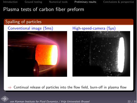
Plasma tests of carbon fiber preform
Spalling of particles
Conventional image (5ms) High-speed-camera (5µs)
) Continual release of particles into the flow field, burn-o↵ in plasma flow
von Karman Institute for Fluid Dynamics / Vrije Universiteit Brussel 22 / 31

Introduction Ground testing Numerical tools Preliminary results Conclusions & perspective
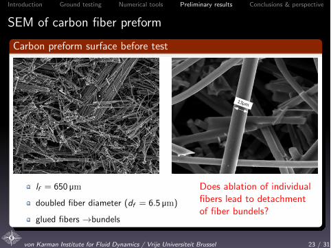
SEM of carbon fiber preform
Carbon preform surface before test
650μm
13μm
lf = 650 µm
doubled fiber diameter (df = 6.5 µm)
glued fibers !bundels
Does ablation of individualfibers lead to detachmentof fiber bundels?
von Karman Institute for Fluid Dynamics / Vrije Universiteit Brussel 23 / 31

Introduction Ground testing Numerical tools Preliminary results Conclusions & perspective
SEM of carbon fiber preform
Carbon preform surface before test
13μm
lf = 650 µm
doubled fiber diameter (df = 6.5 µm)
glued fibers !bundels
Does ablation of individualfibers lead to detachmentof fiber bundels?
von Karman Institute for Fluid Dynamics / Vrije Universiteit Brussel 23 / 31
Introduction Ground testing Numerical tools Preliminary results Conclusions & perspective
SEM of carbon fiber preform
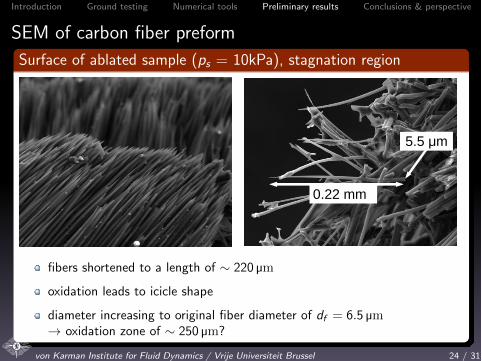
Surface of ablated sample (ps = 10kPa), stagnation region
0.22 mm
5.5 μm
fibers shortened to a length of ⇠ 220 µm
oxidation leads to icicle shape
diameter increasing to original fiber diameter of df = 6.5 µm! oxidation zone of ⇠ 250 µm?
von Karman Institute for Fluid Dynamics / Vrije Universiteit Brussel 24 / 31
Introduction Ground testing Numerical tools Preliminary results Conclusions & perspective
SEM of carbon fiber preform
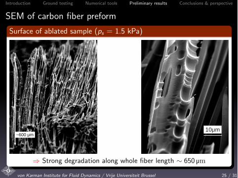
Surface of ablated sample (ps = 1.5 kPa)
~600 μm10μm
) Strong degradation along whole fiber length ⇠ 650 µm
von Karman Institute for Fluid Dynamics / Vrije Universiteit Brussel 25 / 31

Introduction Ground testing Numerical tools Preliminary results Conclusions & perspective
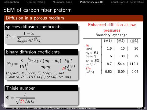
SEM of carbon fiber preformDi↵usion in a porous medium
species di↵usion coe�cients
Di =1� xiPj 6=i xj/Di ,j
binary di↵usion coe�cients
Di ,j =3
16
s2⇡kBT (mi +mj)
mimj
kBT
p⌦(1,1)i ,j
(Capitelli, M., Gorse, C., Longo, S., andGiordano, D., JTHT 14 (2) (2000) 259-268.)
Thiele number
� =Lp
Di/sf kf
Enhanced di↵usion at lowpressures
Boundary layer edge
(#1) (#2) (#3)ps[kPa] 1.5 10 20⇢e ⇥ E4[kg/m3
] 6 38 79cO ⇥ E3[mol/m3
] 8.7 54.4 112.1DO[m2/s] 0.52 0.09 0.04
) valid in continuum flow regime(stagnation region !Knudsennumber)) in porous media defined by mean
pore diameter: Kn = �dp
(Kn > 0.1
possible)
von Karman Institute for Fluid Dynamics / Vrije Universiteit Brussel 26 / 31

Introduction Ground testing Numerical tools Preliminary results Conclusions & perspective
SEM of carbon fiber preformDi↵usion in a porous medium
species di↵usion coe�cients
Di =1� xiPj 6=i xj/Di ,j
binary di↵usion coe�cients
Di ,j =3
16
s2⇡kBT (mi +mj)
mimj
kBT
p⌦(1,1)i ,j
(Capitelli, M., Gorse, C., Longo, S., andGiordano, D., JTHT 14 (2) (2000) 259-268.)
Thiele number
� =Lp
Di/sf kf
Enhanced di↵usion at lowpressures
Boundary layer edge
(#1) (#2) (#3)ps[kPa] 1.5 10 20⇢e ⇥ E4[kg/m3
] 6 38 79
cO ⇥ E3[mol/m3
] 8.7 54.4 112.1DO[m2/s] 0.52 0.09 0.04
) valid in continuum flow regime(stagnation region !Knudsennumber)) in porous media defined by mean
pore diameter: Kn = �dp
(Kn > 0.1
possible)
von Karman Institute for Fluid Dynamics / Vrije Universiteit Brussel 26 / 31
Introduction Ground testing Numerical tools Preliminary results Conclusions & perspective
SEM of carbon fiber preformDi↵usion in a porous medium
species di↵usion coe�cients
Di =1� xiPj 6=i xj/Di ,j
binary di↵usion coe�cients
Di ,j =3
16
s2⇡kBT (mi +mj)
mimj
kBT
p⌦(1,1)i ,j
(Capitelli, M., Gorse, C., Longo, S., andGiordano, D., JTHT 14 (2) (2000) 259-268.)
Thiele number
� =Lp
Di/sf kf
Enhanced di↵usion at lowpressures
Boundary layer edge
(#1) (#2) (#3)ps[kPa] 1.5 10 20⇢e ⇥ E4[kg/m3
] 6 38 79cO ⇥ E3[mol/m3
] 8.7 54.4 112.1DO[m2/s] 0.52 0.09 0.04
) valid in continuum flow regime(stagnation region !Knudsennumber)) in porous media defined by mean
pore diameter: Kn = �dp
(Kn > 0.1
possible)
von Karman Institute for Fluid Dynamics / Vrije Universiteit Brussel 26 / 31

Introduction Ground testing Numerical tools Preliminary results Conclusions & perspective
SEM of carbon fiber preformDi↵usion in a porous medium
species di↵usion coe�cients
Di =1� xiPj 6=i xj/Di ,j
binary di↵usion coe�cients
Di ,j =3
16
s2⇡kBT (mi +mj)
mimj
kBT
p⌦(1,1)i ,j
(Capitelli, M., Gorse, C., Longo, S., andGiordano, D., JTHT 14 (2) (2000) 259-268.)
Thiele number
� =Lp
Di/sf kf
Enhanced di↵usion at lowpressures
Boundary layer edge
(#1) (#2) (#3)ps[kPa] 1.5 10 20⇢e ⇥ E4[kg/m3
] 6 38 79cO ⇥ E3[mol/m3
] 8.7 54.4 112.1DO[m2/s] 0.52 0.09 0.04
) valid in continuum flow regime(stagnation region !Knudsennumber)) in porous media defined by mean
pore diameter: Kn = �dp
(Kn > 0.1
possible)von Karman Institute for Fluid Dynamics / Vrije Universiteit Brussel 26 / 31

Introduction Ground testing Numerical tools Preliminary results Conclusions & perspective
Outline
1 Introduction
2 Ground testing in Plasmatron facility
3 Numerical tools development
4 Results with a carbon fiber preform (preliminary)
5 Conclusions and perspective
von Karman Institute for Fluid Dynamics / Vrije Universiteit Brussel 27 / 31
Introduction Ground testing Numerical tools Preliminary results Conclusions & perspective
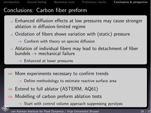
Conclusions: Carbon fiber preform
Enhanced di↵usion e↵ects at low pressures may cause strongerablation in di↵usion-limited regime
Oxidation of fibers shows variation with (static) pressure
! Conform with theory on species di↵usion
Ablation of individual fibers may lead to detachment of fiberbundels ! mechanical failure
! Enhanced at lower pressures
) More experiments necessary to confirm trends
! Define methodology to estimate reactive surface area
) Extend to full ablator (ASTERM, AQ61)
) Modelling of carbon preform ablation tests
! Start with control volume approach suppressing pyrolysis
von Karman Institute for Fluid Dynamics / Vrije Universiteit Brussel 28 / 31

Introduction Ground testing Numerical tools Preliminary results Conclusions & perspective
Perspectives for ablation studies at the VKI
Testing condition and boundary layer characterization
) Application of LHTS methodology to ablation testing) Uncertainty quantification methods
Mircoscale analysis of virgin and tested ASTERM / AQ61
) Comparison to preform (no phenolic impregnation)) Definition of reactive surface needed, char layer depth, porosity
Very high heat-flux testing
) Appropriate measurement techniques
Reference test case definition for model validation
Flight extrapolation methodology
von Karman Institute for Fluid Dynamics / Vrije Universiteit Brussel 29 / 31

Introduction Ground testing Numerical tools Preliminary results Conclusions & perspective
Perspectives: Extend ablation framework to related studiesat VKI
Converging nozzle
Supersonic plasma flow studies atVKI
Extension to high heat fluxtesting (aim: 10MW/m2)
QB50 / flight demonstrator
50 double-unit cubesats:in-situ, multipoint &long-duration measurements
10 triple-unit cubesats:re-entry flight demonstrator forablation studies
von Karman Institute for Fluid Dynamics / Vrije Universiteit Brussel 30 / 31
Introduction Ground testing Numerical tools Preliminary results Conclusions & perspective
Questions?
Acknowledgements
AFOSR
ESA
Lockheed Martin UK (Ampthill)
Mersen Scotland Holytown Ltd.
EADS Astrium ST
Agency for Innovation by Science and Technology (IWT)
N.N. Mansour, J. Lachaud, J.-M. Bouilly
[email protected] Karman Institute for Fluid Dynamics / Vrije Universiteit Brussel 31 / 31


![v/;k; & 6scert.cg.gov.in/dedodldistance201213...gSaA ';ke dh cksyh lkQ ugha gS] igyh ckj vki mldh ckr ugha le> ldrs ysfdu tc vki ,d ckj mlls ckr djus yxs rks vki mldh cksyh le> ldrs](https://img.dokumen.tips/doc/110x75/5ff9cdb6270f0c2b9a0b73b1/vk-gsaa-ke-dh-cksyh-lkq-ugha-gs-igyh-ckj-vki-mldh-ckr-ugha-le.jpg)