Embed Size (px)
Citation preview
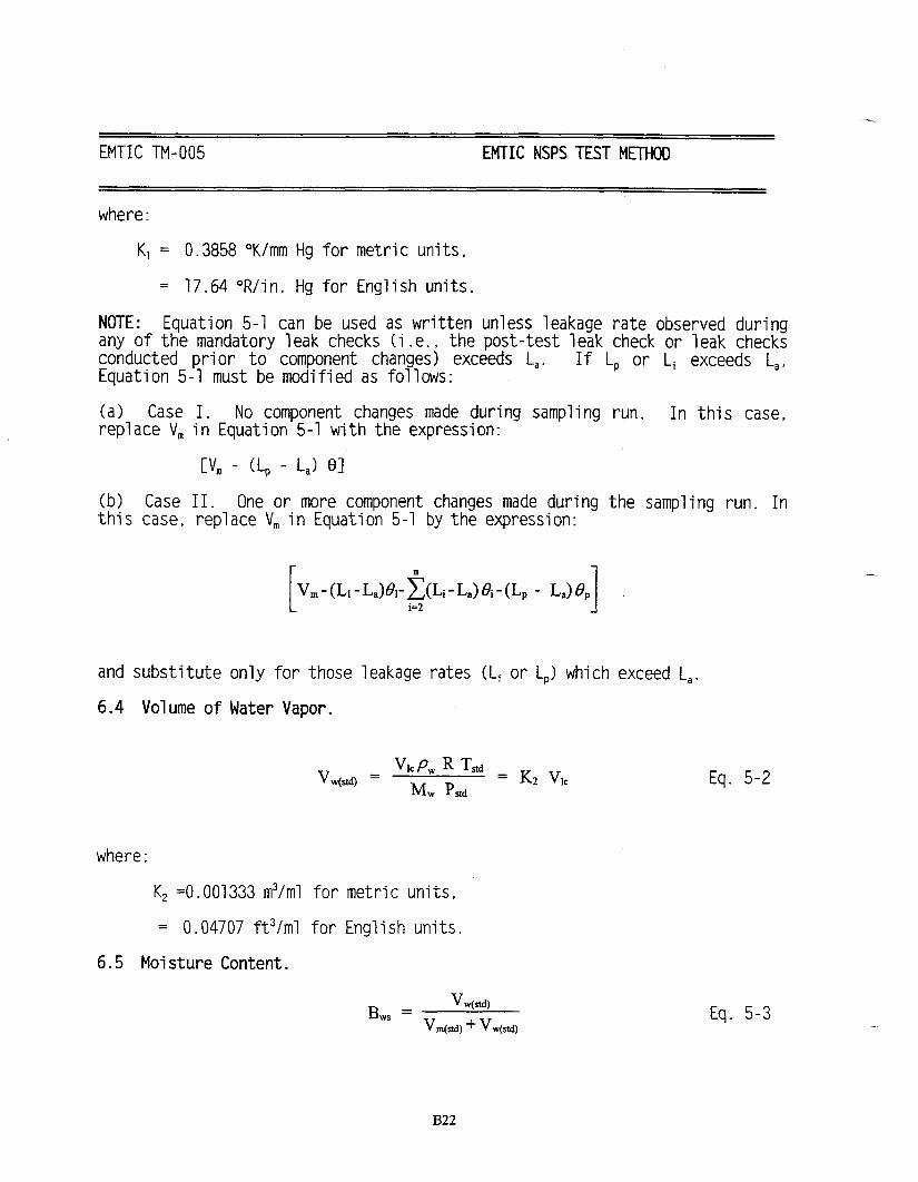
METHOD 8A - DETERMINATION OF SULFURIC ACID VAPOROR MIST AND SULFUR DIOXIDE EMISSIONS FROM
KRAFT RECOVERY FURNACES
NCASISouthern Regional Center
December 1996
i
Acknowledgments
This method was prepared by Ashok K. Jain, Regional Manager at the NCASI Southern RegionalCenter.
For more information about this method, contact:
Ashok K. JainNCASIP. O. Box 141020Gainesville, FL 32614-1020(352) 377-4708, ext. 226FAX (352) 371-6557
For information about NCASI publications, contact:
Publications CoordinatorNCASIP. O. Box 13318Research Triangle Park, NC 27709-3318(919) 558-1987
National Council of the Paper Industry for Air and Stream Improvement, Inc. (NCASI). 1997.Methods Manual, Method 8 - Determination of Sulfuric Acid Vapor or Mist and Sulfur DioxideEmissions from Kraft Recovery Furnaces, Research Triangle Park, N.C.: National Council of thePaper Industry for Air and Stream Improvement, Inc.
© 1997 by the National Council of the Paper Industry for Air and Stream Improvement, Inc.
NCASI’s MissionTo serve the forest products industry as a center of excellence for providing technicalinformation and scientific research needed to achieve the industry’s environmental goals.

ii
Disclaimer
The mention of trade names or commercial products does not constitute endorsement orrecommendation for use.

1 December 1996
METHOD 8A - DETERMINATION OF SULFURIC ACID VAPOROR MIST AND SULFUR DIOXIDE EMISSIONS FROM
KRAFT RECOVERY FURNACES
1.0 Introduction
This method was developed as an alternative to EPA Method 8 for determining sulfuricacid emissions from kraft recovery furnaces. When testing recovery furnaces, EPAMethod 8 is subject to significant interference from sulfates, which are present in theparticulate matter, and sulfur dioxide. The alternative method uses a quartz in-line filterto remove particulate matter from the gas stream prior to capturing sulfuric acid. The useof a controlled condensation technique eliminates the potential for interference fromsulfur dioxide.
EPA approved the use of Method 8A in December 1996 for the determination of acidvapor or mist and sulfur dioxide emissions from kraft recovery furnaces.
2.0 Method Description
2.1 Principle and applicability
2.1.1 Principle - A gas sample is extracted from the sampling point in the recoveryfurnace stack. The sulfuric acid vapor or mist (including sulfur trioxide) and thesulfur dioxide are separated, and both fractions are measured separately by thebarium-thorin titration method.
2.1.2 Applicability - This method is applicable for the determination of sulfuric acidvapor or mist (including sulfur trioxide, and in the presence of other particulatematter) and sulfur dioxide emissions from kraft recovery furnaces. Tests haveshown the minimum detectable limits of the method are 0.50 milligrams/cubicmeter (3.1 x 10⁻⁸ lb/ft3) for sulfur trioxide. No upper limits have been established. Based on theoretical calculations, for 200 mL of 3% hydrogen peroxide solution,the upper concentration limit for sulfur dioxide in a 1.0 m3 (35.3 ft3) gas sample isabout 12,500 mg/m3 (7.7 x 10⁻⁴ lb/ft3). The upper limit can be extended byincreasing the quantity of peroxide solution in the impingers.
Possible interfering agents of this method are fluorides, free ammonia, dimethylaniline and recovery furnace salt cake.
2.2 Apparatus
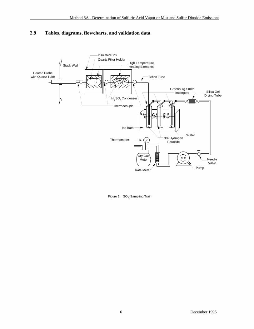
2.2.1 Sampling - A schematic of the sampling train used in this method is shown inFigure 1. Component parts are discussed below. The schematic is similar to theEPA Method 6 (see Appendix A) train except that the impingers are not the midgettype but larger as in the EPA Method 8 (see Appendix C) train. Also, the

Method 8A - Determination of Sulfuric Acid Vapor or Mist and Sulfur Dioxide Emissions
2 December 1996
impingers are preceded by a heated sampling probe, a heated quartz filter holderand a heated H2SO4 condenser.
2.2.1.1 Probe - Quartz, straight tube approximately 12-mm inside diameter,with a heating element and a stainless steel jacket. A thermocoupletaped on the quartz tube and insulated with glass wool allows formeasurement of the probe temperature.
2.2.1.2 Sulfuric acid sampling box - Insulated box with heating elements forfilter holder and H2SO4 condenser.
(a) Filter holder - Quartz, as described in Figure 2. Filter mediumis Tissuequartz filter paper with a 37-mm diameter (PallflexCorporation). Filter holder is always maintained attemperatures >260°C (500°F) by a cylindrical heating mantle.
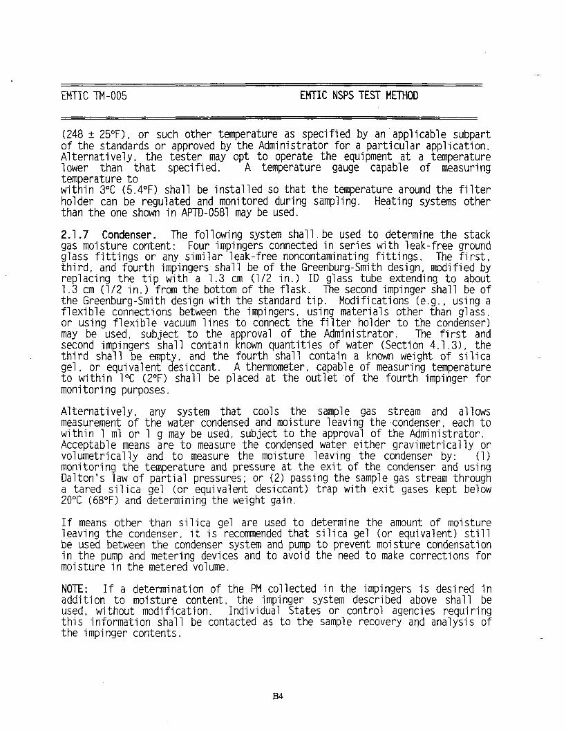
(b) H2SO4 condenser - Modified Grahm condenser, with Type Cglass frit and 200 cm of 5-mm ID glass tubing for condensercoil, as shown in Figure 3. Condenser filled with water andtemperature maintained between 75 and 85°C (167 to 185°F)with a cylindrical heating mantle.
2.2.1.3 Thermocouples - Copper-constantan thermocouples to measuretemperatures at the probe end, after the filter holder and after theH2SO4 condenser (see Figure 1).
2.2.1.4 Impingers - Three, as shown in Figure 1. The first and thirdimpingers shall be of the Greenburg-Smith design with standard tips. The second shall be of the Greenburg-Smith design, modified byreplacing the insert with an approximately 13 mm (0.5 in.) ID glasstube, having an unconstricted tip located 13 mm (0.5 in.) from thebottom of the flask.
2.2.1.5 Metering system - Same as EPA Method 6, Sections 2.1.5 to 2.1.10,except rotameter should be capable of measuring flow rate to within2% of the selected flow rate of about 10,000 cc/min (and not 1,000cc/min).
2.2.1.6 Barometer - Same as EPA Method 6, Section 2.1.11.
2.2.1.7 Vacuum gauge and rotameter - Same as EPA Method 6, Section2.1.12.
2.2.2 Sample Recovery - Same as EPA Method 8, Section 2.2.
2.2.3 Analysis - Same as EPA Method 8, Section 2.3.

Method 8A - Determination of Sulfuric Acid Vapor or Mist and Sulfur Dioxide Emissions
3 December 1996
2.3 Reagents
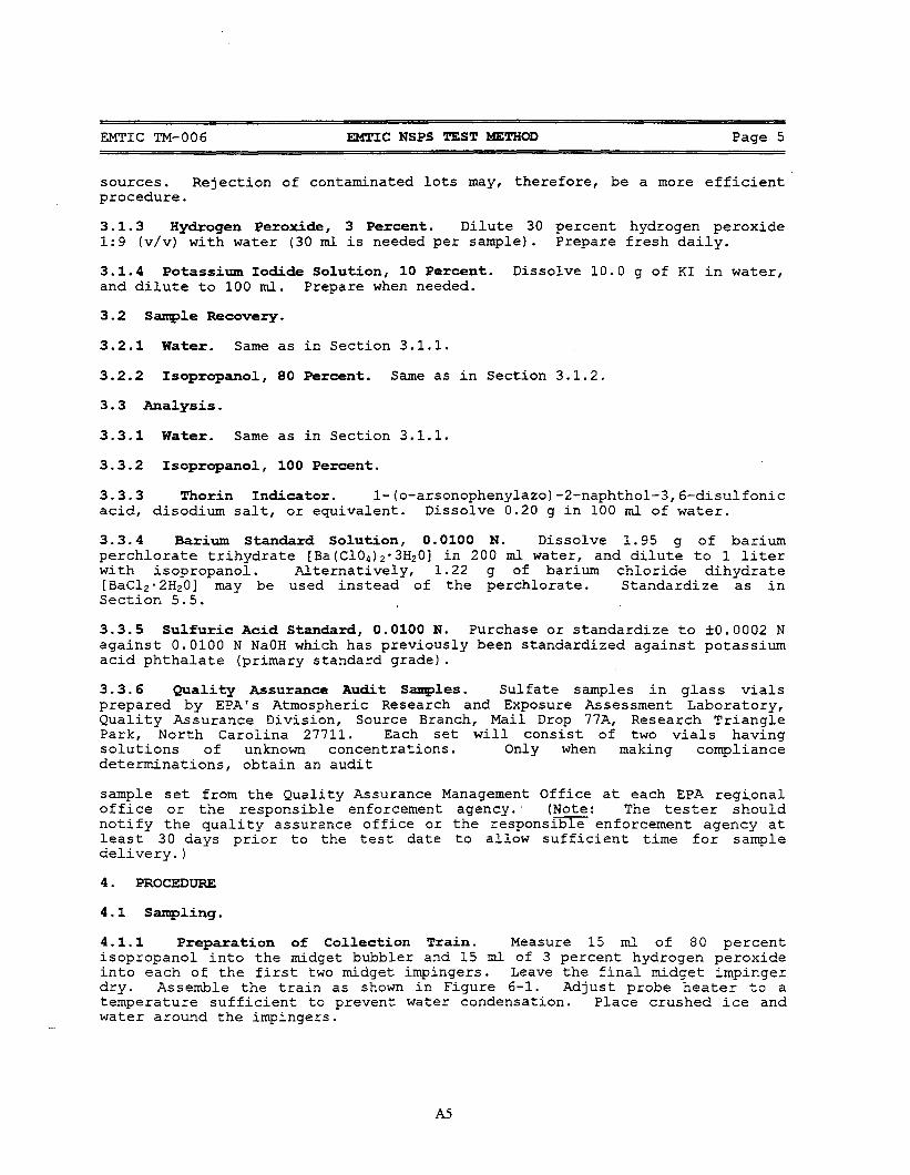
2.3.1 Sampling
2.3.1.1 Filters - Tissuequartz filter papers with a 37-mm diameter (PallflexCorporation).
2.3.1.2 Silica Gel, Water, Hydrogen Peroxide, Crushed Ice - Same asdescribed in EPA Method 8, Section 3.1.3 to 3.1.6.
2.3.2 Sample Recovery - Water. Same as for EPA Method 8, Section 3.2.
2.3.3 Analysis
2.3.3.1 Water, thorin indicator, barium perchlorate and sulfuric acidstandard - Same as for EPA Method 8, Section 3.3.
2.4 Procedure
2.4.1 Sampling
2.4.1.1 Preparation of collection train - Measure 100 mL of 3% hydrogenperoxide into each of the first two impingers. Pour 100 mL of distilleddeionized water into the third impinger. Retain a portion of eachreagent used as a blank solution. Assemble the train as shown inFigure 1. Adjust probe heater to maintain probe temperature above177°C (350°F) to prevent condensation of H2SO4 in the gas passingthrough the probe. Adjust heaters to the quartz filter and sulfuric acidcondenser to the desired temperatures given in Sections 2.2.1.2 (a) and2.2.1.2 (b). Place crushed ice around the impingers.
2.4.1.2 Leak-check procedure - Follow the procedure laid out in EPAMethod 8, Section 4.1.4.
2.4.1.3 Sample collection - Record the initial dry gas meter reading andbarometric pressure (see data sheet, Figure 4). To begin sampling,position the tip of the probe at the sampling point at right angles todirection of gas flow, connect the probe, filter and condenser assemblyto the first impinger, and start the pump. Adjust the sample flow to aconstant rate of about 10.0 L/min as indicated by the rotameter. Maintain this constant rate (+10%) during the entire sampling run. Sample for a minimum of 30 minutes and take readings (dry gas meter,temperatures at dry gas meter, probe, filter and condenser) at leastevery five minutes (Figure 4). Add more ice during the run if needed.At the conclusion of each run, turn off the pump, remove probe fromthe stack, and record the final readings. Conduct a leak check as

Method 8A - Determination of Sulfuric Acid Vapor or Mist and Sulfur Dioxide Emissions
4 December 1996
described in Section 2.4.1.2. (This leak check is mandatory.) If thepost-leakage rate exceeds the specified acceptable rate (see Section4.1.4 of EPA Method 8), the tester shall either correct the samplevolume, as specified in Section 6.3 of EPA Method 5 (see AppendixB), or shall void the run.
Drain the ice bath and, with the probe disconnected, purge theremaining part of the train by drawing clean ambient air through thesystem for 15 minutes at the average flow rate used for sampling (seeSection 4.1.5 of EPA Method 8 for details).
2.4.2 Sample recovery - Disconnect the impingers after purging. Rinse separately theprobe, quartz filter holder and the H2SO4 condenser with deionized water usingmultiple rinses for good washing. Collect the condenser wash solution inContainer No. 1, and the No. 1 and No. 2 impinger solutions in Container No. 2. Note levels of liquids in each container.
2.4.3 Sample analysis - Note the level of liquid in containers 1 and 2, and confirmwhether or not any sample was lost during shipment; note this on the analyticaldata sheet. If a noticeable amount of leakage has occurred, either void the sampleor use methods, subject to the approval of the administrator, to correct the finalresults.
2.4.3.1 Container no. 1 - Transfer the entire contents of Container no. 1 into a250 mL Erlenmeyer flask, add enough isopropyl alcohol to give an80% isopropyl alcohol solution. Pipette a 100-mL aliquot of thissolution into a 250-mL Erlenmeyer flask, add 2 to 4 drops of thorinindicator, and titrate to a pink end point using 0.0100 N bariumperchlorate. Repeat the titration with a second aliquot of sample andaverage the titration values. Replicate titrations must agree within 1%or 0.2 mL, whichever is greater. Caution: The H2SO4 concentrations inkraft recovery furnace stacks are typically so low that at times almostthe entire sample in Container no. 1 may have to be used during thetitration.
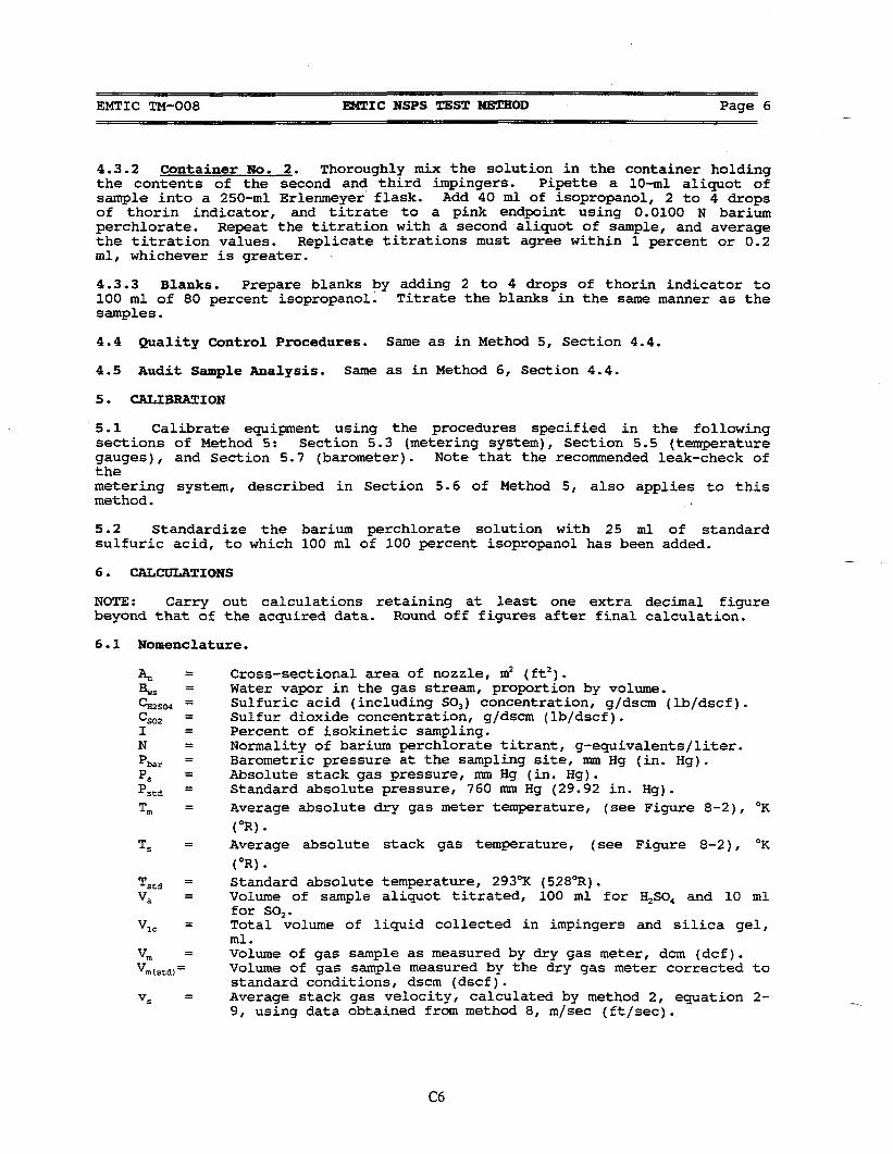
2.4.3.2 Container no. 2 - If concurrent SO2 concentrations in the stack aredesired carry out the following. Thoroughly mix the solution inContainer no. 2 which holds the contents of the 1st and 2nd impingers. Pipette a 10-mL aliquot of this solution into a 250-mL Erlenmeyerflask. Add 40 mL isopropanol, 2 to 4 drops of thorin indicator, andtitrate to a pink end point using 0.0100 N barium perchlorate. Repeatthe titration with a second aliquot of sample and average the titrationvalues. Replicate titrations must agree within 1% or 0.2 mL,whichever is greater.

Method 8A - Determination of Sulfuric Acid Vapor or Mist and Sulfur Dioxide Emissions
5 December 1996
2.4.3.3 Blanks - Prepare blanks by adding 2 to 4 drops of thorin indicator to100 mL of 80% isopropanol. Titrate the blanks in the same manner asthe samples.
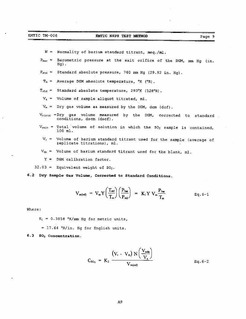
2.5 Calibration - Same as Section 5 of EPA Method 8.
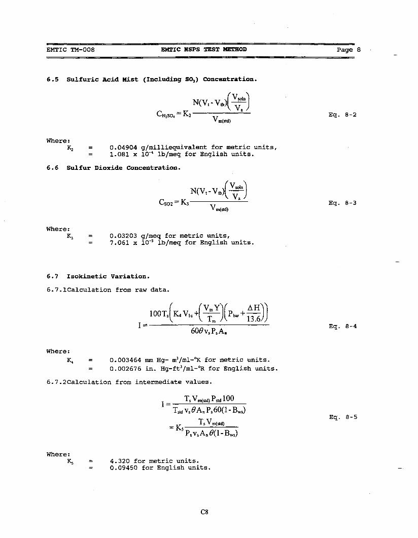
2.6 Calculations - Same as Section 6 of EPA Method 8, except that equation 8-1 should bereplaced by equation 6-1 of EPA Method 6, and references to isokinetic sampling in thissection should be omitted. Recovery furnace stack gas temperatures are expected to behigher than the estimated dewpoint of H2SO4 in the stack gas, and H2SO4 is expected tobe present in vapor phase only. Consequently, neither isokinetic sampling nor a stacktraverse is required.
2.7 Alternative procedures - Not applicable to this method.
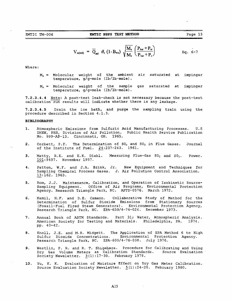
2.8 References
National Council of the Paper Industry for Air and Stream Improvement, Inc. (NCASI). 1980. A study of SOx measurement procedures and their use at kraft recovery furnaces. Atmospheric Quality Improvement Technical Bulletin No. 106. Research Triangle Park,NC: National Council of the Paper Industry for Air and Stream Improvement, Inc.
Method 8A - Determination of Sulfuric Acid Vapor or Mist and Sulfur Dioxide Emissions
6 December 1996
2.9 Tables, diagrams, flowcharts, and validation data
Figure 1. SO Sampling TrainX
Heated Probe with Quartz Tube
Stack Wall
Insulated BoxQuartz Filter Holder
High Temperature Heating Elements
H SO Condenser 2 4
Thermocouple
Teflon Tube
Silica Gel Drying Tube
Water3% Hydrogen
Peroxide
Rate Meter
Thermometer
Ice Bath
Greenburg-Smith Impingers
Needle Valve
Pump
Dry Gas Meter

Method 8A - Determination of Sulfuric Acid Vapor or Mist and Sulfur Dioxide Emissions
7 December 1996
28/15 Ball
Spring Attachment Hooks
Tissue Quartz Filter Thermocouple Well
28/15 Socket
Extra Coarse Quartz Fit
Standard Taper Quartz 40/50
Seal Extension to Std. Taper Joint
Figure 2. Quartz Filter Holder

Method 8A - Determination of Sulfuric Acid Vapor or Mist and Sulfur Dioxide Emissions
8 December 1996
Glass Jacket
Gas Sample In
Sintered Glass Filter
Figure 3. H SO Condenser2 4

Method 8A - Determination of Sulfuric Acid Vapor or Mist and Sulfur Dioxide Emissions
9 December 1996
Source ____________ Date _________________
Run No. __________ Furnace Load ________________
Stack Gas Temp. _____________ Atmospheric Pressure _________
Final Dry Gas Meter Reading _________
Initial Dry Gas Meter Reading _________
Volume Sampled ____________________
Temperature, °FDry Gas Meter
Time (min) Probe Filter Condenser In Out
0
5
10
15
20
25
30
Figure 4. SO3 Measurement Field Data Sheet

Method 8A - Determination of Sulfuric Acid Vapor or Mist and Sulfur Dioxide Emissions
10 December 1996
Figure 5. EPA Approval Letter