Embed Size (px)
DESCRIPTION
Piping welding works procedures
Citation preview

METHOD STATEMENT FOR PIPE WELDING WORKS

Introduction This Method statement describes in detail the welding process for pipe work and the
welder’s qualification test procedures. This includes addressing programs for
implementing commitments regarding the quality of welding works.
Contents
1.0 Scope and Purpose of Method Statement
2.0 Index
3.0 Description of Activities
4.0 List of Main Equipment
5.0 Health, Safety and Environment Measures
1.0 Scope and Purpose of Method Statement This document outlines the method for executing welding process for pipe work and
welding procedure qualification test for welders. This method statement covers all
piping welding works for Burj Dubai Tower Project either shop fabricated or site
installed.
The procedure provides guidance for assessing the activities for jointing mechanical
piping system. This guidance is based on the requirements set forth in the Safety
Requirement Document (SRD) and The Quality Assurance Program (QAP).
1.1 Objectives This document provides guidance in implementing an effective program for all pipe
welding works. This includes addressing programs for the following: (1) implementing
commitments regarding the quality of the weld joints; (2) managing and providing
oversight to ensure installation and related quality control have been adequately
addressed by specifications, drawings, and procedures; (3) managing and providing
supervision and control to assure qualification of welders; and (4) recording installation
and test activities.
This procedure is one component of a complete construction and inspection program.
This and other procedures will be used, as needed, to provide assurance that construction
activities are being conducted as required by the specification and manufacturer
procedures. It is not expected that completion of the entire procedure will be
accomplished during any one inspection and/or every time the inspection procedure is
used. It is a continuing activity until all piping networks are installed and tested.
2
1.2 Inspection and Recording Requirements The engineer should verify that the supervisor/foreman with construction
responsibilities for the pipe welding works is familiar with this method statement and is
issued with copies of the inspection checklists and test plans.
The engineer should satisfy procedures provided by QA/QC inspections to ensure the
pipe welding works meet specified engineering requirements and drawings. As part of
the assessment, the QC Inspection Procedures, must ensure a quantitative or qualitative
acceptance criteria for determining the prescribed activities have been accomplished
satisfactorily.
The QC inspection personnel, in coordination with Site Supervisor, should verify that
the quality of the pipe welding works and related testing activities are within the project
design specifications requirements.
The Supervisor should verify that the pipe welding works is accomplished in
accordance with the specifications and the manufacturer’s procedures.
The Supervisor should verify any as-built record of pipe welding works and testing, and
confirm that the information meets the project requirements.
1.3 Inspection Guidance Pipe welding works need to follow strictly established codes and safety procedures.
Care should be taken to ensure that applicable codes and standards be strictly adhered to
during pipe welding works.
The Supervisor can choose to follow the most appropriate welding technique applicable
at such a given time and in coordination with the construction progress, QA/QC
inspection and testing requirements. The Engineers should use judgment in determining
sample selection focusing on examination of the most important aspects of the particular
welding activity being inspected. The intent is to establish a high level of assurance that
the end product meets the project requirements.
Review the implementing procedures and safety standards for the pipe welding works
provided by the QA/QC. The QA/QC inspectors should verify that the procedures (1)
are approved, and (2) specify the requirements of the design and/or from the
manufacture’s technical manual(s) and codes or standards prescribed by the Client.
1.4 Training and Qualification of Personnel The Supervisor should verify that the personnel have sufficient knowledge of the
procedure requirements. The Supervisor should review any training and qualification
3
records for those individuals who shall do the task to determine whether they are skilled
enough to follow the procedure before the actual work is carried out.
2.0 Index 2.1 Preparation of Materials and Execution of Works
• General
• Pipe Joint Preparation
• Pipe to Pipe Fit Up
• 45° Elbow to Pipe Fit Up
• 90° Elbow to Pipe Fit Up
• Tee to Pipe Fit Up
• Flange to Pipe Fit Up
2.2 Welding Procedure Qualification Test Requirements
• Welding Process
• Base Metals
• Filler Metals
• Position of Groove & Weld Progression
• Temperature Requirements
• Postweld Heat Treatment
• Type of Gas
• Electrical Characteristics
• Travel Speed & Passes
• Laboratory Test Results
4

3.0 Description of Activities 3.1 General
• Check all pipes and fittings to be used for joint are free from
defects, dents or deformities and are straight. Remove pipes and
fittings with defects and replace with acceptable materials.
• Remove foreign matter or dirt from inside of the pipe and fittings
before fit up.
• For longer work breaks, place suitable stoppers to prevent debris,
earth or water from entering pipe open ends.
• Welding electrodes shall be stored and handled as per
Manufacturer’s instructions.
3.2 Pipe Joint Preparation
• Cut the pipes to the required length using an appropriate pipe
cutter, or profile cutter (Oxy-Acetylene), allowing for provision of
pipe fitting later. Works shall be carried out in accordance with the
approved shop drawings.
• The pipes shall be checked by the assigned foreman for its
squareness and straightness, after being cut to the correct angle and
site requirements, as per sample of welding details in Figure 1
shown below.
5

Figure 1 – Sample of Welding Details
6

3.3 Pipe to Pipe Fit Up
• Lay the two (2) pipes on top of the pipe stand or adjustable support,
with each pipe ends aligned near each other using adjustable bolt
stopper as shown on Figure 2 below.
Figure 2 – Pipe to Pipe Fit Up
Note : For larger sizes only, 4”dia. and above
• Level one length of pipe using spirit level.
• Bring lengths together leaving only a small welding gap. In normal
practice, a welding electrode of 2.4 mm Ø size, removed of its
covering and bent in the middle at an angle of 30° is inserted
between the two pipes to obtain a perfect welding gap. It is
recommended to weld adjustable bolt stoppers (small piece of
plate about 12 mm thick with an M-16 hexagon bolt and nut
welded at one end as shown in Figure 2) for perfect and easy
alignment.
7
• Remove the adjustable bolt stoppers after fit up and grind flush all
tack welded points making sure that there is no over grinding of
the base metal.
• Place the spirit level over both pipes as shown on Figure 2 and
maneuver until both pipes are leveled. Adjusting the pipe support
can easily do this. Ensure that there is no high-low situation or
misalignment between the two outside surfaces.
• Tack weld at the top and bottom.
• Rotate the pipes 90°.
• Repeat the same procedure.
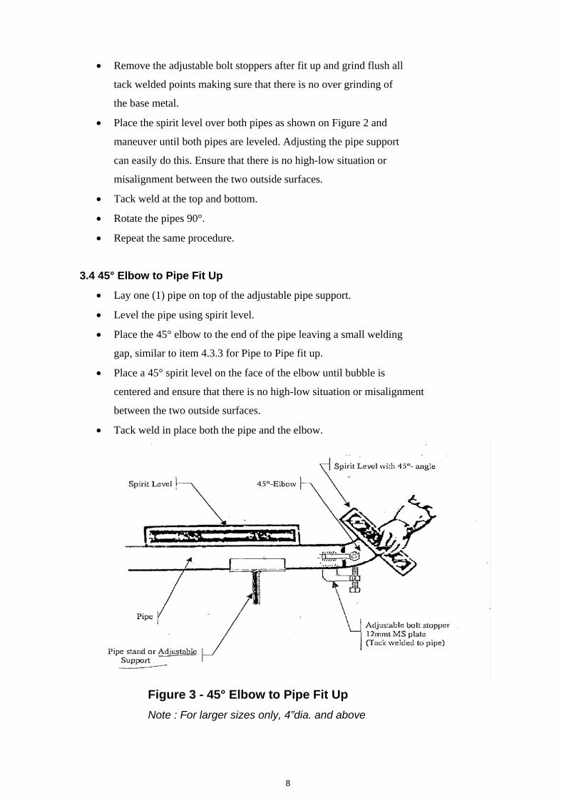
3.4 45° Elbow to Pipe Fit Up
• Lay one (1) pipe on top of the adjustable pipe support.
• Level the pipe using spirit level.
• Place the 45° elbow to the end of the pipe leaving a small welding
gap, similar to item 4.3.3 for Pipe to Pipe fit up.
• Place a 45° spirit level on the face of the elbow until bubble is
centered and ensure that there is no high-low situation or misalignment
between the two outside surfaces.
• Tack weld in place both the pipe and the elbow.
Figure 3 - 45° Elbow to Pipe Fit Up Note : For larger sizes only, 4”dia. and above
8

3.5 90° Elbow to Pipe Fit Up
• Lay one (1) pipe on top of the adjustable pipe supports.
• Level the pipe using spirit level.
• Place the 90° elbow to end of the pipe leaving a small welding
gap the same as item 4.3.3 for Pipe to Pipe Fit up.
• Place a spirit level on the face of the elbow and maneuver the
elbow until it is leveled and ensure that there is no high-low
situation or misalignment between the two outside surfaces.
• Tack weld in place both the pipe and elbow.
Figure 4 - 90° Elbow to Pipe Fit Up Note : For larger sizes only, 4”dia. and above
9
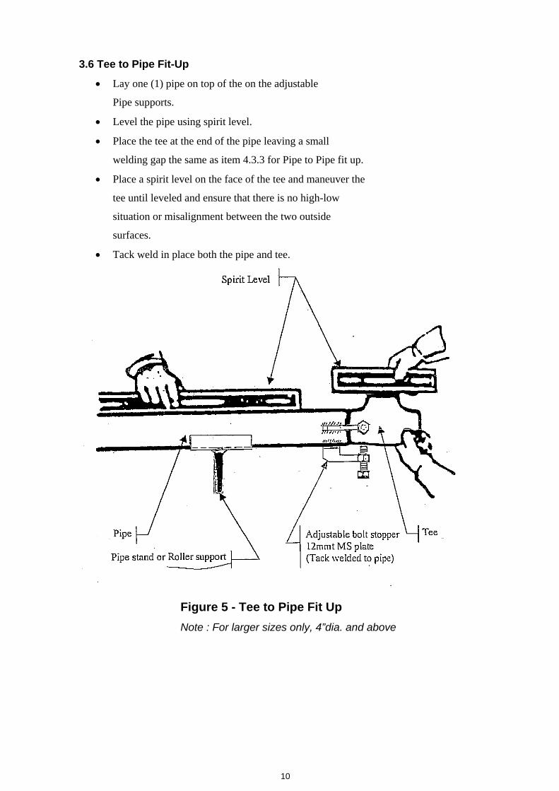
3.6 Tee to Pipe Fit-Up
• Lay one (1) pipe on top of the on the adjustable
Pipe supports.
• Level the pipe using spirit level.
• Place the tee at the end of the pipe leaving a small
welding gap the same as item 4.3.3 for Pipe to Pipe fit up.
• Place a spirit level on the face of the tee and maneuver the
tee until leveled and ensure that there is no high-low
situation or misalignment between the two outside
surfaces.
• Tack weld in place both the pipe and tee.
Figure 5 - Tee to Pipe Fit Up Note : For larger sizes only, 4”dia. and above
10
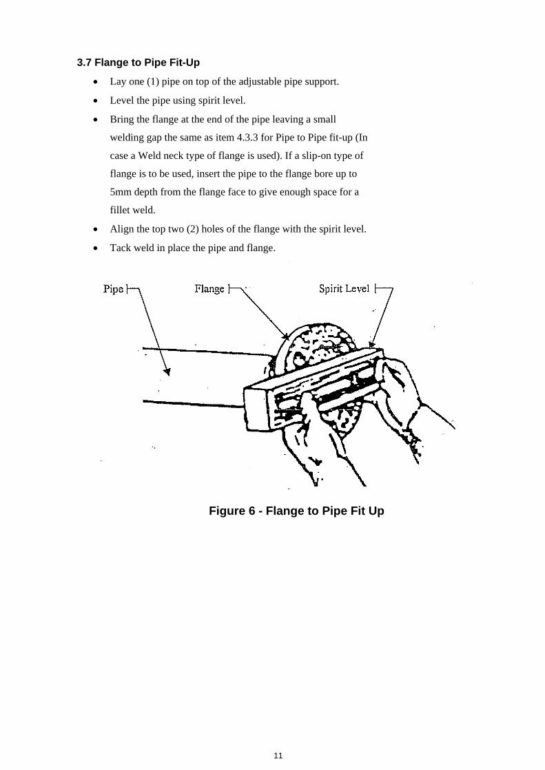
3.7 Flange to Pipe Fit-Up
• Lay one (1) pipe on top of the adjustable pipe support.
• Level the pipe using spirit level.
• Bring the flange at the end of the pipe leaving a small
welding gap the same as item 4.3.3 for Pipe to Pipe fit-up (In
case a Weld neck type of flange is used). If a slip-on type of
flange is to be used, insert the pipe to the flange bore up to
5mm depth from the flange face to give enough space for a
fillet weld.
• Align the top two (2) holes of the flange with the spirit level.
• Tack weld in place the pipe and flange.
Figure 6 - Flange to Pipe Fit Up
11

TYPICAL DETAILS OF ADJUSTABLE BOLT
STOPPER USE FOR PIPE FIT UP and ALIGNMENT Note : For larger sizes only, 4”dia. and above
12
4.0 List of Main Equipment, Tools, Instruments
4.1 EQUIPMENT AND TOOLS
A. Boom truck
B. Chain blocks (1Ton – 5Ton Cap.)
C. A-frame (steel fabricated)
D. Nylon sling or straps (New and tested)
E. Set of shackles
F. Adjustable bolt stopper
G. Adjustable pipe supports
H. Spirit level
I. Alignment Tools (Plumb Bob, Chalk line, Nylon String Line, Felt Tip Marker)
J. Welding Personnel Protective Equipments
K. Hand tools
M. Steel measuring tape
N. Angle & Straight Grinders
O. Welding Machines
P. Steel Scaffolding and Ladders
5.0 Health, Safety and Environment Measures 5.1 Preparation
Notify all concerned in site for the date of material delivery.
- Coordinate with Safety Department for delivery trucks access routes.
- Ensure all workers involved in the hauling operation put on PPE all times.
- Brief individual worker the roles and responsibilities of each.
- Ensure transporter route is cleared of obstruction.
- Coordinate with Construction Department for Pipe Hoisting area.
- Ensure designated hoisting area is cleared of obstruction.
- The lorry transporting the pipes will be guided to the designated hoisting
area and released all the latching belts only after the lorry parked firmly.
5.2 Pipe Lifting
- Ensure safe work procedure for lifting operation is observed.
- Ensure proper lifting method - with the correct equipments are used.
- Ensure the pipes are firmly placed on the designated location before
releasing the hoisting hook.
13
5.3 During Site Execution
- Ensure workers are distributed to each designated place.
- Ensure workers at all times to be in proper gear where required.
- Ensure all workers assigned are involved in its particular task.
- Brief individual worker the roles and responsibilities before start work.
- Ensure the pipe lengths to suit site routes into designated work area.
- Ensure pipe support systems are installed accordingly as required.
- Ensure all tools to be used have been inspected and tag by Safety Dept.
- Ensure work areas are clearly marked to restrict access to authorized
personnel only.
- Ensure that equipments to be used are properly tagged and checked.
- Ensure that welders are qualified, with the correct PPEs, and well versed on the
job at hand with the latest revised drawing/s.
5.4 Housekeeping
- Maintain cleanliness and orderly stocking of materials & tools.
- Pick up and dispose wastes & other debris prior to leaving site area.
- Remove safety yellow tape or other warning devices that were used to
control access to the work area.
- Store tools, equipment and unused materials properly at the end of the
workday.
5.5 Safety Inspections
- It shall be responsibility of the Supervisor to routinely inspect the physical
areas under their control in pipe welding works. This inspection shall
include determining if pipes, supports, scaffolds and ladders are
appropriately installed and/or use, and if the job site is cleaned up after the
day’s work.
14

INSPECTION CHECKLIST FOR
WELDING MONITORING
Report No. :……...... Contractor’s Name :….… …………. Description of Works : ..…Pipe Welding.......... Reference No. : ……………………………. Date Prepared : …………………………… Specific Location……………………………… Inspection Requested : Date …………… Time ……………. ITEMS TO BE PERFORMED Accept Reject Hold Remarks 1. WELDING ELECTRODES & CONSUMABLES 1.1 Type of Consumables
1.2 Type used is per approved submittal (Yes/No)
1.3 Storage condition & handling satisfactory
2. WELDING PROCEDURE MONITORING 2.1 Type of Joint
2.2 Joint Alignment
2.3 Champer uniform & free of ripples or notches
2.4 Root Face ( height per approved WPS )
2.5 Tack welds
2.6 Root gap and free from foreign matter
2.7 Interpass cleaning & slag removal
2.8 Root Pass inspection
2.9 Interpass temperature
2.10 Electrical requirements
2.11 Welding speed & number of passes
2.12 Welding Process (SMAW/GTAW/SAW/GMAW) 3. VISUAL INSPECTION 3.1 Welder stamp identified (Hard Stamped)
3.2 Joint Number
3.3 Welds acceptability per code
3.4 Width & height of capping pass acceptable
Observations : Signature Name Date
15


![Using%20 twitter%20for%20employability[2]](https://img.dokumen.tips/doc/110x75/555db9b0d8b42a68328b55e2/using20-twitter20for20employability2.jpg)


![15%20 things%20i’m%20thankful%20for[1]](https://img.dokumen.tips/doc/110x75/5592d4c21a28ab34118b47ae/1520-things20im20thankful20for1.jpg)