Embed Size (px)
Citation preview

November 2020
METERING COST-EFFECTIVENESS ASSESSMENT TOOL User Guide
Reduced input cost effectiveness tool (RCET) V1.1 Full input cost effectiveness tool (FCET) V1.0

© Crown copyright 2020
This publication is licensed under the terms of the Open Government Licence v3.0 except where otherwise stated. To view this licence, visit nationalarchives.gov.uk/doc/open-government-licence/version/3 or write to the Information Policy Team, The National Archives, Kew, London TW9 4DU, or email: [email protected].
Where we have identified any third-party copyright information you will need to obtain permission from the copyright holders concerned.
Any enquiries regarding this publication should be sent to us at: [email protected]
3
Contents Introduction _______________________________________________________________ 6
The Reduced input cost effectiveness assessment tool (RCET) _______________________ 7
Reduced User Inputs (RCET) _________________________________________________ 7
Overview (RCET) _________________________________________________________ 7
Section 1: Network and Building Setup (RCET) __________________________________ 7
Network Inputs _________________________________________________________ 8
Building Inputs _________________________________________________________ 8
Section 3: Fuel Consumption (RCET)__________________________________________ 8
Fuel Inputs ____________________________________________________________ 9
Section 3: Unit types within building (RCET) ___________________________________ 11
Overview _____________________________________________________________ 11
Building Unit Inputs _____________________________________________________ 12
Section 4: Quoted costs (RCET) ____________________________________________ 14
Overview _____________________________________________________________ 14
Metering Cost Inputs ____________________________________________________ 14
Tool Outputs (RCET) _______________________________________________________ 15
Cost / Benefit Analysis (RCET) ______________________________________________ 15
Overview _____________________________________________________________ 15
Methodology __________________________________________________________ 15
Energy Saved _________________________________________________________ 16
Meter installation _______________________________________________________ 17
Data gathering equipment ________________________________________________ 17
Operational costs for meters and HCAs _____________________________________ 17
Installation of user controls _______________________________________________ 17
HCA Installation _______________________________________________________ 17
Water meter installation _________________________________________________ 17
The Full input cost effectiveness assessment tool (FCET) __________________________ 18
User Inputs (FCET) ________________________________________________________ 18
Overview _______________________________________________________________ 18
Network and Building Setup ________________________________________________ 18
Network Inputs ________________________________________________________ 19
Building Inputs ________________________________________________________ 19
Building Input Buttons ___________________________________________________ 23
Fuel Consumption _______________________________________________________ 26
4
Fuel Inputs ___________________________________________________________ 26
Heat generating plant within or outside the building ______________________________ 29
Plant Inputs ___________________________________________________________ 29
Plant input buttons _____________________________________________________ 33
Unit types within building __________________________________________________ 34
Overview _____________________________________________________________ 34
Building Unit Inputs _____________________________________________________ 35
Building Unit macro buttons ______________________________________________ 40
Tool Outputs (FCET) _______________________________________________________ 41
Integrity Check __________________________________________________________ 41
Appraisal _______________________________________________________________ 42
Core Calculations (FCET) ___________________________________________________ 44
Underlying principles _____________________________________________________ 44
Establishing demand ____________________________________________________ 44
Cost assumptions ______________________________________________________ 44
Detailed Energy Calculations _______________________________________________ 45
Energy Demand _______________________________________________________ 45
Energy Supply Calculations ________________________________________________ 48
Overview _____________________________________________________________ 48
Energy dispatch hierarchy not provided by user _______________________________ 48
Heat / cooling supply ____________________________________________________ 49
Fuel consumption ______________________________________________________ 50
Fuel Cost _____________________________________________________________ 50
Cost / Benefit Analysis ____________________________________________________ 50
Overview _____________________________________________________________ 50
Methodology __________________________________________________________ 50
Energy Saved _________________________________________________________ 51
Meter installation _______________________________________________________ 51
Data gathering equipment ________________________________________________ 52
Operational costs for meters and HCAs _____________________________________ 52
Installation of user controls _______________________________________________ 52
HCA Installation _______________________________________________________ 52
Water meter installation _________________________________________________ 52
Appendix 1 (FCET): CIBSE Values used ________________________________________ 53
External Walls ___________________________________________________________ 53
1. Stone Walls ______________________________________________________ 53
5
2. No fines concrete walls _____________________________________________ 53
3. Solid brick walls ___________________________________________________ 54
4. Dense concrete walls _______________________________________________ 54
5. Precast concrete panel walls _________________________________________ 55
6. Brick/brick cavity walls ______________________________________________ 56
7. Brick/dense concrete block cavity walls _________________________________ 56
8. Brick/lightweight aggregate concrete block cavity walls _____________________ 57
9. Brick/autoclaved aerated concrete block cavity walls ______________________ 58
10. Timber Frame Walls________________________________________________ 58
External Floors __________________________________________________________ 59
1. Ground contact solid concrete floors ___________________________________ 59
2. Ground contact suspended timber floors ________________________________ 60
3. Outside air contact floors ____________________________________________ 60
External Roofs __________________________________________________________ 62
1. Flat concrete roofs _________________________________________________ 62
2. Flat timber roofs ___________________________________________________ 62
3. Pitched roofs (insulated at ceiling level) _________________________________ 63
4. Pitched roofs (insulated at rafter level)__________________________________ 64
5. Sheet metal construction ____________________________________________ 65
Glazing types ___________________________________________________________ 65
Double glazed, air filled __________________________________________________ 65
Double glazed, air filled, low-E ____________________________________________ 66
Double glazed, argon filled _______________________________________________ 66
Double glazed, argon filled, low-E __________________________________________ 66
Triple glazed, air filled ___________________________________________________ 67
Triple glazed, air filled, low-E _____________________________________________ 67
Triple glazed, argon filled ________________________________________________ 67
Triple glazed, argon filled, low-E ___________________________________________ 67
Single glazed _________________________________________________________ 68
With secondary glazing __________________________________________________ 68

Full and Reduced cost effectiveness assessment tool – User Guide
6
Introduction Enabling existing communal and district heat networks to consistently evaluate whether heat meters or heat cost allocators should or should not be installed in buildings connected in line with the requirements of the Energy Efficiency Directives (2012/27 EU and 2018/2002/EU).
A full input and reduced input Microsoft Excel tool (the tools) have been developed to assist with the economic appraisal of whether heat meters, or failing that, heat cost allocators should or should not be installed within specific buildings that fall within the definition of communal or district heating networks. The tools have been developed to materially adhere to the European Commission’s 2016 “Guidelines on good practice in cost-effective cost allocation and billing of individual consumption of heating, cooling and domestic hot water in multi-apartment and multi-purpose buildings”1.
The underlying assumption of better metering is that consumption patterns will change when heat customers are aware of how much heat they consume. Research undertaken by the European Commission (see the guidance document) suggests that heat metering can reduce domestic heat consumption by 20% and non-domestic heat consumption by 10%2. The fuel saved is taken as the benefit of installing heat meters, a benefit that should accrue to the customer.
However, installing heat meters or heat cost allocators will incur costs to a heat supplier. The discounted costs to the heat supplier are weighed against the discounted benefit to the customer over a 10 year period. If the present value of the benefits are greater than the present value of the estimated (or actual) cost of installing and managing heat meters for a given building then the tools will recommend that heat meters are installed in each such building.
If the present value of the costs are greater than or equal to the discounted benefits then the tools assess if the present value of the benefits outweigh the present value of the costs associated with installing heat cost allocators. If they do, then the tools will recommend the installation of heat cost allocators for all such buildings.
1 Empirica GmbH (2016) ‘Guidelines on good practice in cost-effective cost allocation and billing of individual consumption of heating, cooling and domestic hot water in multi-apartment and multi-purpose buildings’ (available at: https://ec.europa.eu/energy/sites/ener/files/documents/mbic_guidelines20170123_en.pdf 2 ibid

Full and Reduced cost effectiveness assessment tool – User Guide
7
The Reduced input cost effectiveness assessment tool (RCET) The reduced input cost effectiveness tool has been designed to allow compliance with the Heat Network (Metering and Billing) (Amendment) Regulations 2020 cost effectiveness assessment requirements where energy consumption for a building is known and a quote for heat metering device installation and billing costs has been sought.
Reduced User Inputs (RCET)
Overview (RCET)
The reduced user input sheet is intended to allow the user to assess a single building on their network and input sufficient information to allow net present value (NPV) calculations to be carried out for the installation of heat metering devices. A building is added by the user and the user sets out the actual heat or coolth consumption of the building, its use type and metering requirements. Cost information from a quote from a metering provider is then entered to provide actual installation costs. In this way the user is able to tailor the assessment to their actual buildings.
All user inputs are labelled with a reference number in Column B of the user input sheet of the tool. The calculations section below explains how each user input is used in order to derive key values to establish the cost/benefit analysis for the installation of heat meters or heat cost allocators.
Section 1: Network and Building Setup (RCET)
Input labels and supporting descriptions
Network Inputs
Building Inputs
Full and Reduced cost effectiveness assessment tool – User Guide
8
Network Inputs
Network Name [1] (mandatory) The network name is a mandatory field and should be the unique identification number provided by the regulator or if this is not known a name that the user readily associates with the network (communal or district) that is being assessed. A building cannot be entered into the tool unless this field is populated.
Network geographical location [2] (mandatory) The network’s geographical location is a mandatory field and requires the user to select the region of the UK that the network is located in. In the unlikely event that a network spans across more than one UK region please select the region where majority of customers are located.
Network unique identification number [3] (optional) The network’s unique identification number is an optional field where the user can enter the networks unique identification number if they know it.
Building Inputs
Building Name [A1] (mandatory)
This should be the name of the building that is to be assessed for the installation of either heat meters or heat cost allocators. For example, imagine a district heat network of 10 buildings is being assessed. Each of the 10 buildings 5 would be entered into a separate reduced input tool and a separate name for each of the 10 buildings would be provided in this field upon entry of each building.
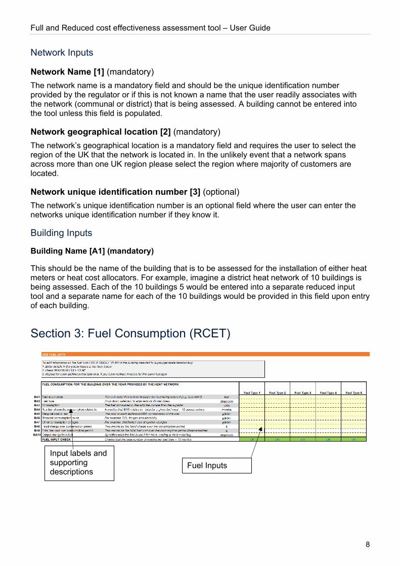
Section 3: Fuel Consumption (RCET)
Input labels and supporting descriptions
Fuel Inputs
Full and Reduced cost effectiveness assessment tool – User Guide
9
Fuel Inputs
Overview The user must complete Section ADD FUEL DATA for the building. This section allows the user to enter 12 months of fuel costs and accompanying information, rather than entering the specific heat/cooling plant used to supply heat/cooling to the building (permitted in the full input tool). As the tool is evaluating the annual savings that are forecast to be delivered through the installation of a heat meter or heat cost allocator, it is imperative that the user enters exactly 12 months of fuel costs attributable to the building selected. It is possible to enter multiple invoices separately into the tool; however, the total months for a given fuel type must add to 12. Where dual fuel (or potentially more still) is used to supply heat/cooling to a building (e.g. biomass and gas) then the total months entered for each fuel type [BA2] must add to 12.
Evidence for the costs entered should be retained for 7 years. If the values are not directly reconcilable to an energy supplier invoice then a clear reconciliation should be prepared and filed with supporting evidence.
Fuel description [BA1] (mandatory) This field is solely for the benefit of the user to be able to refer to relevant invoices, reconciliations etc. for example, “Natural gas June 2020 invoice”.
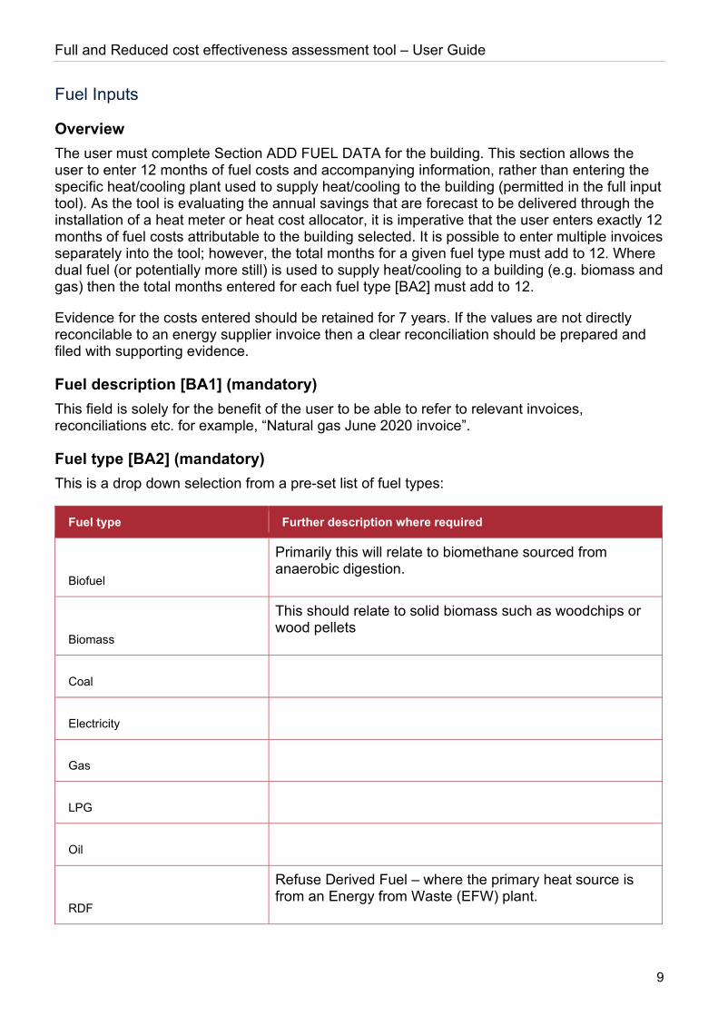
Fuel type [BA2] (mandatory) This is a drop down selection from a pre-set list of fuel types:
Fuel type Further description where required
Biofuel
Primarily this will relate to biomethane sourced from anaerobic digestion.
Biomass
This should relate to solid biomass such as woodchips or wood pellets
Coal
Electricity
Gas
LPG
Oil
RDF
Refuse Derived Fuel – where the primary heat source is from an Energy from Waste (EFW) plant.
Full and Reduced cost effectiveness assessment tool – User Guide
10
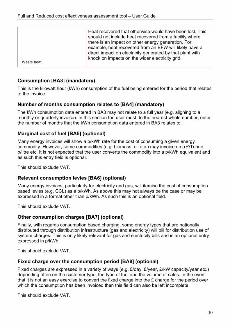
Waste heat
Heat recovered that otherwise would have been lost. This should not include heat recovered from a facility where there is an impact on other energy generation. For example, heat recovered from an EFW will likely have a direct impact on electricity generated by that plant with knock on impacts on the wider electricity grid.
Consumption [BA3] (mandatory) This is the kilowatt hour (kWh) consumption of the fuel being entered for the period that relates to the invoice.
Number of months consumption relates to [BA4] (mandatory) The kWh consumption data entered in BA3 may not relate to a full year (e.g. aligning to a monthly or quarterly invoice). In this section the user must, to the nearest whole number, enter the number of months that the kWh consumption data entered in BA3 relates to.
Marginal cost of fuel [BA5] (optional) Many energy invoices will show a p/kWh rate for the cost of consuming a given energy commodity. However, some commodities (e.g. biomass, oil etc.) may invoice on a £/Tonne, p/litre etc. It is not expected that the user converts the commodity into a p/kWh equivalent and as such this entry field is optional.
This should exclude VAT.
Relevant consumption levies [BA6] (optional) Many energy invoices, particularly for electricity and gas, will itemise the cost of consumption based levies (e.g. CCL) as a p/kWh. As above this may not always be the case or may be expressed in a format other than p/kWh. As such this is an optional field.
This should exclude VAT.
Other consumption charges [BA7] (optional) Finally, with regards consumption based charging, some energy types that are nationally distributed through distribution infrastructure (gas and electricity) will bill for distribution use of system charges. This is only likely relevant for gas and electricity bills and is an optional entry expressed in p/kWh.
This should exclude VAT.
Fixed charge over the consumption period [BA8] (optional) Fixed charges are expressed in a variety of ways (e.g. £/day, £/year, £/kW capacity/year etc.) depending often on the customer type, the type of fuel and the volume of sales. In the event that it is not an easy exercise to convert the fixed charge into the £ charge for the period over which the consumption has been invoiced then this field can also be left incomplete.
This should exclude VAT.
Full and Reduced cost effectiveness assessment tool – User Guide
11
Total fuel cost over the consumption period [BA9] (mandatory) This should be the total amount payable for the period invoiced and must exclude VAT but include all other charges.
Output energy from fuel [BA10] (mandatory) This can be one of:
Output energy type
Heat
Cooling
Heat & cooling
Most fuel types will typically be used to deliver either heat or cooling; however, some fuel types might be used to deliver both (e.g. electricity, waste heat recovery). The significance of selecting heat & cooling is that the cost of fuel will be apportioned in ratio of the heat: cooling demand estimated by the tool.
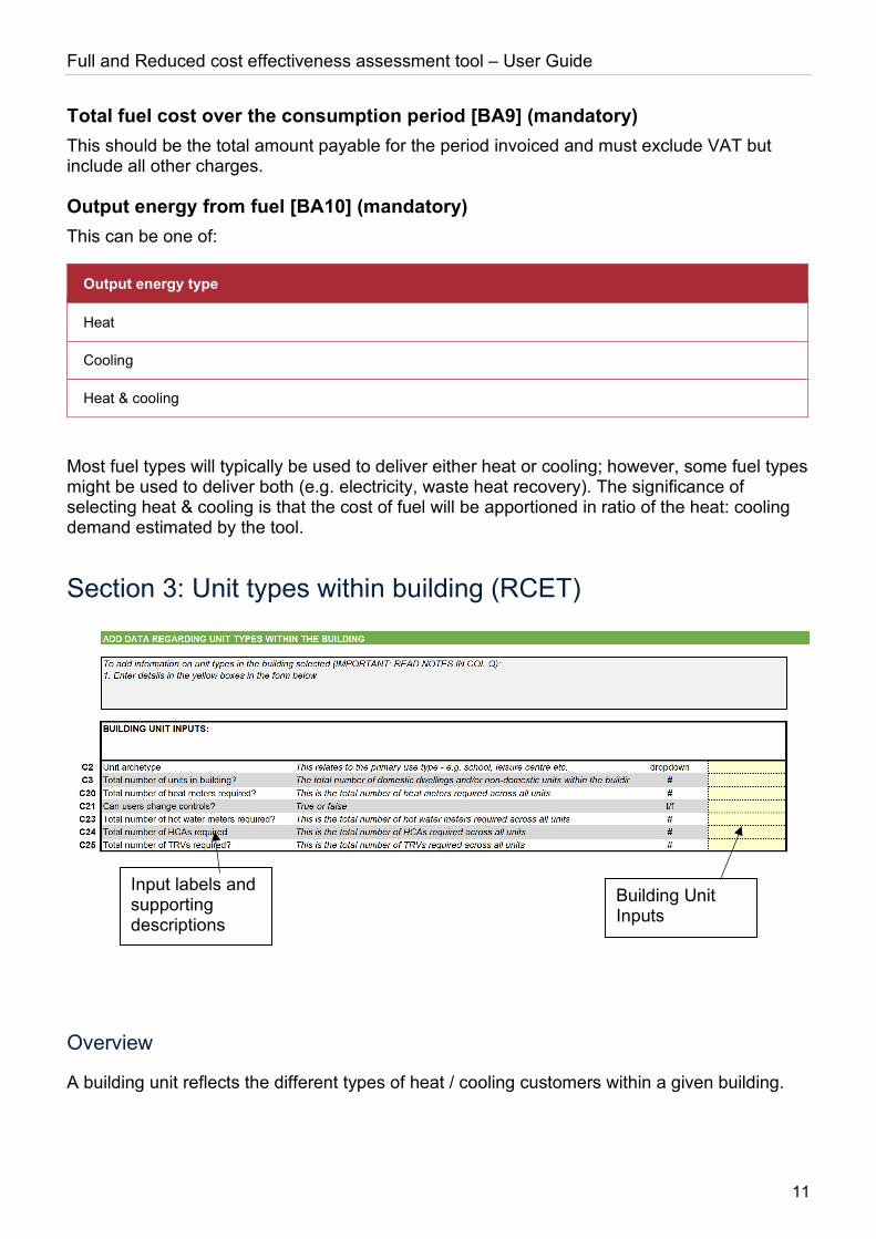
Section 3: Unit types within building (RCET)
Overview
A building unit reflects the different types of heat / cooling customers within a given building.
Building Unit Inputs
Input labels and supporting descriptions
Full and Reduced cost effectiveness assessment tool – User Guide
12
Building Unit Inputs
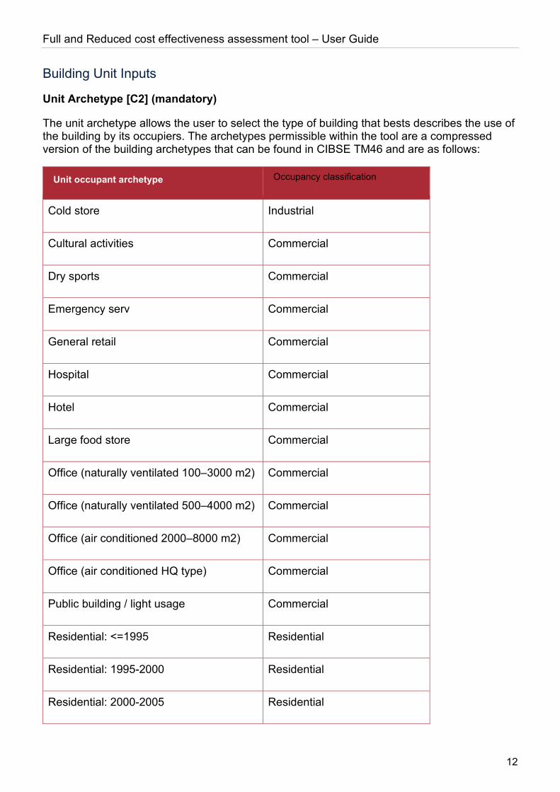
Unit Archetype [C2] (mandatory)
The unit archetype allows the user to select the type of building that bests describes the use of the building by its occupiers. The archetypes permissible within the tool are a compressed version of the building archetypes that can be found in CIBSE TM46 and are as follows:
Unit occupant archetype Occupancy classification
Cold store Industrial
Cultural activities Commercial
Dry sports Commercial
Emergency serv Commercial
General retail Commercial
Hospital Commercial
Hotel Commercial
Large food store Commercial
Office (naturally ventilated 100–3000 m2) Commercial
Office (naturally ventilated 500–4000 m2) Commercial
Office (air conditioned 2000–8000 m2) Commercial
Office (air conditioned HQ type) Commercial
Public building / light usage Commercial
Residential: <=1995 Residential
Residential: 1995-2000 Residential
Residential: 2000-2005 Residential
Full and Reduced cost effectiveness assessment tool – User Guide
13
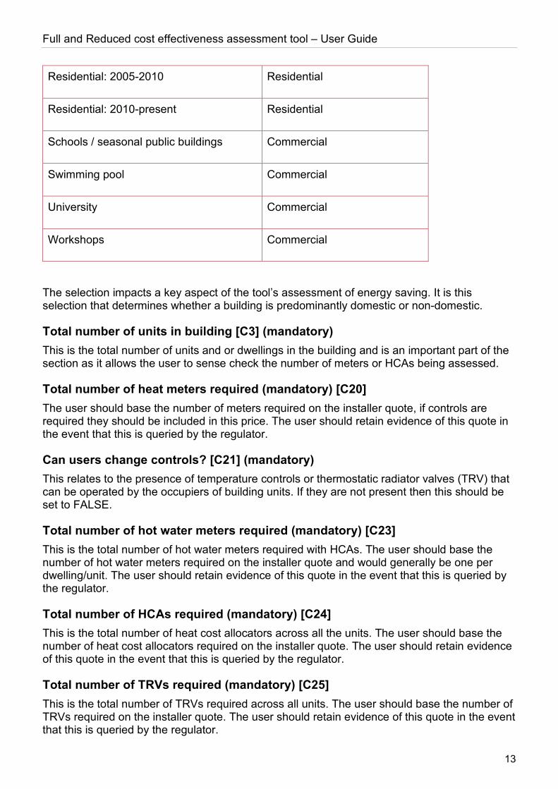
Residential: 2005-2010 Residential
Residential: 2010-present Residential
Schools / seasonal public buildings Commercial
Swimming pool Commercial
University Commercial
Workshops Commercial
The selection impacts a key aspect of the tool’s assessment of energy saving. It is this selection that determines whether a building is predominantly domestic or non-domestic.
Total number of units in building [C3] (mandatory) This is the total number of units and or dwellings in the building and is an important part of the section as it allows the user to sense check the number of meters or HCAs being assessed.
Total number of heat meters required (mandatory) [C20] The user should base the number of meters required on the installer quote, if controls are required they should be included in this price. The user should retain evidence of this quote in the event that this is queried by the regulator.
Can users change controls? [C21] (mandatory) This relates to the presence of temperature controls or thermostatic radiator valves (TRV) that can be operated by the occupiers of building units. If they are not present then this should be set to FALSE.
Total number of hot water meters required (mandatory) [C23] This is the total number of hot water meters required with HCAs. The user should base the number of hot water meters required on the installer quote and would generally be one per dwelling/unit. The user should retain evidence of this quote in the event that this is queried by the regulator.
Total number of HCAs required (mandatory) [C24] This is the total number of heat cost allocators across all the units. The user should base the number of heat cost allocators required on the installer quote. The user should retain evidence of this quote in the event that this is queried by the regulator.
Total number of TRVs required (mandatory) [C25] This is the total number of TRVs required across all units. The user should base the number of TRVs required on the installer quote. The user should retain evidence of this quote in the event that this is queried by the regulator.
Full and Reduced cost effectiveness assessment tool – User Guide
14
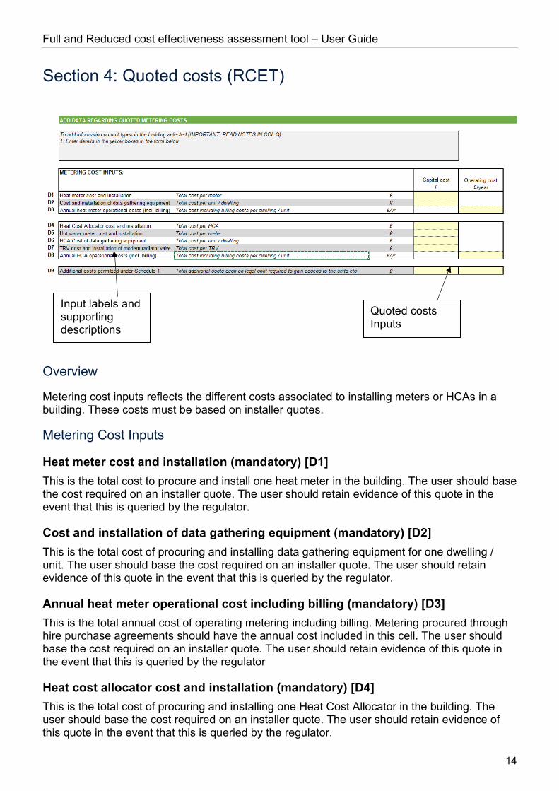
Section 4: Quoted costs (RCET)
Overview
Metering cost inputs reflects the different costs associated to installing meters or HCAs in a building. These costs must be based on installer quotes.
Metering Cost Inputs
Heat meter cost and installation (mandatory) [D1] This is the total cost to procure and install one heat meter in the building. The user should base the cost required on an installer quote. The user should retain evidence of this quote in the event that this is queried by the regulator.
Cost and installation of data gathering equipment (mandatory) [D2] This is the total cost of procuring and installing data gathering equipment for one dwelling / unit. The user should base the cost required on an installer quote. The user should retain evidence of this quote in the event that this is queried by the regulator.
Annual heat meter operational cost including billing (mandatory) [D3] This is the total annual cost of operating metering including billing. Metering procured through hire purchase agreements should have the annual cost included in this cell. The user should base the cost required on an installer quote. The user should retain evidence of this quote in the event that this is queried by the regulator
Heat cost allocator cost and installation (mandatory) [D4] This is the total cost of procuring and installing one Heat Cost Allocator in the building. The user should base the cost required on an installer quote. The user should retain evidence of this quote in the event that this is queried by the regulator.
Quoted costs Inputs
Input labels and supporting descriptions

Full and Reduced cost effectiveness assessment tool – User Guide
15
Hot water meter cost and installation (mandatory) [D5] This is the total cost to procure and install one hot water meter in the building. The user should base the cost required on an installer quote. The user should retain evidence of this quote in the event that this is queried by the regulator.
HCA cost of data gathering equipment (mandatory) [D6] This is the total cost of procuring and installing data gathering equipment for one dwelling / unit. The user should base the cost required on an installer quote. The user should retain evidence of this quote in the event that this is queried by the regulator.
TRV cost and installation of a modern radiator valve (mandatory) [D7] This is the total cost of procuring and installing one Thermostatic Radiator Valve in the building. The user should base the cost required on an installer quote. The user should retain evidence of this quote in the event that this is queried by the regulator.
Annual HCA operational cost including billing (mandatory) [D8] This is the total annual cost of operating HCA including billing. HCAs procured through hire purchase agreements should have the annual cost included in this cell. The user should base the cost required on an installer quote. The user should retain evidence of this quote in the event that this is queried by the regulator.
Additional costs permitted under Schedule 1 (mandatory) [D9] This is the total of all additional costs permitted in Schedule 1 of the regulations such as legal costs or signal booster costs if required. The user must be able to evidence these additional costs should they be included for example by having a quote from a solicitor for additional legal costs. The user should retain evidence to support these additional costs in the event that this is queried by the regulator
Tool Outputs (RCET)
Cost / Benefit Analysis (RCET)
Overview
The cost / benefit analysis (CBA) assesses whether the benefit of the fuel estimated to be saved by the heat / cooling customer when a heat meter or heat cost allocators are installed does or does not outweigh the cost of their installation, maintenance and monitoring over the assessment period.
Methodology
The CBA is calculated on a building by building basis. The assessment for heat meters can be summarised as follows:
Cash Flow Unit 1 2 3 4 5 6 7 8 9 10
Energy Saved £ + + + + + + + + + +
Full and Reduced cost effectiveness assessment tool – User Guide
16
Meter installation £ -
Data gathering equipment
£ -
Meter operational costs
£ - - - - - - - - - -
Installation of user controls
£ -
Net Cash Flow £ - + + + + + + + + +
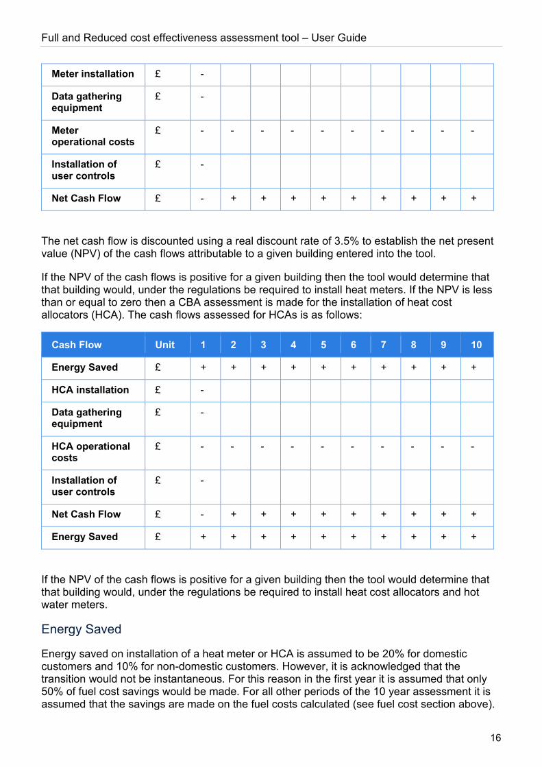
The net cash flow is discounted using a real discount rate of 3.5% to establish the net present value (NPV) of the cash flows attributable to a given building entered into the tool.
If the NPV of the cash flows is positive for a given building then the tool would determine that that building would, under the regulations be required to install heat meters. If the NPV is less than or equal to zero then a CBA assessment is made for the installation of heat cost allocators (HCA). The cash flows assessed for HCAs is as follows:
Cash Flow Unit 1 2 3 4 5 6 7 8 9 10
Energy Saved £ + + + + + + + + + +
HCA installation £ -
Data gathering equipment
£ -
HCA operational costs
£ - - - - - - - - - -
Installation of user controls
£ -
Net Cash Flow £ - + + + + + + + + +
Energy Saved £ + + + + + + + + + +
If the NPV of the cash flows is positive for a given building then the tool would determine that that building would, under the regulations be required to install heat cost allocators and hot water meters.
Energy Saved
Energy saved on installation of a heat meter or HCA is assumed to be 20% for domestic customers and 10% for non-domestic customers. However, it is acknowledged that the transition would not be instantaneous. For this reason in the first year it is assumed that only 50% of fuel cost savings would be made. For all other periods of the 10 year assessment it is assumed that the savings are made on the fuel costs calculated (see fuel cost section above).
Full and Reduced cost effectiveness assessment tool – User Guide
17
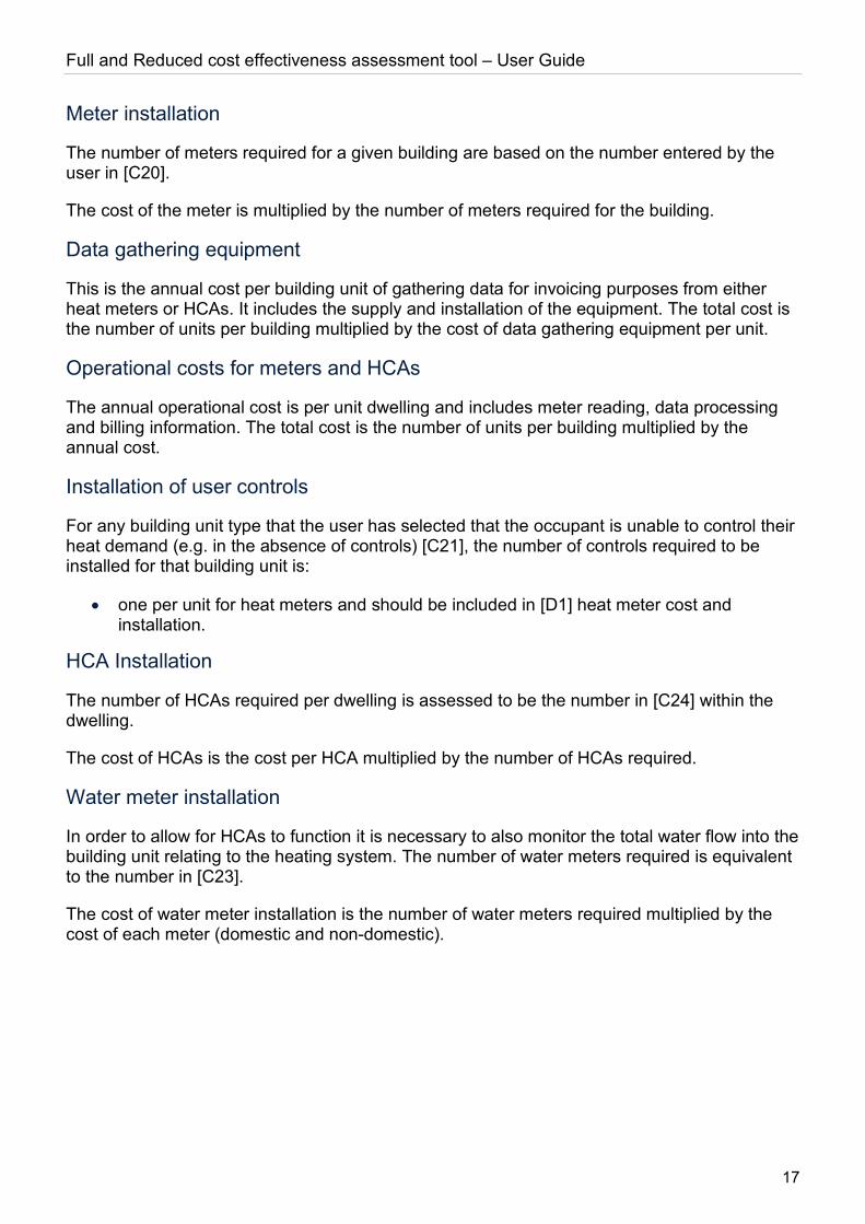
Meter installation
The number of meters required for a given building are based on the number entered by the user in [C20].
The cost of the meter is multiplied by the number of meters required for the building.
Data gathering equipment
This is the annual cost per building unit of gathering data for invoicing purposes from either heat meters or HCAs. It includes the supply and installation of the equipment. The total cost is the number of units per building multiplied by the cost of data gathering equipment per unit.
Operational costs for meters and HCAs
The annual operational cost is per unit dwelling and includes meter reading, data processing and billing information. The total cost is the number of units per building multiplied by the annual cost.
Installation of user controls
For any building unit type that the user has selected that the occupant is unable to control their heat demand (e.g. in the absence of controls) [C21], the number of controls required to be installed for that building unit is:
• one per unit for heat meters and should be included in [D1] heat meter cost and installation.
HCA Installation
The number of HCAs required per dwelling is assessed to be the number in [C24] within the dwelling.
The cost of HCAs is the cost per HCA multiplied by the number of HCAs required.
Water meter installation
In order to allow for HCAs to function it is necessary to also monitor the total water flow into the building unit relating to the heating system. The number of water meters required is equivalent to the number in [C23].
The cost of water meter installation is the number of water meters required multiplied by the cost of each meter (domestic and non-domestic).
Full and Reduced cost effectiveness assessment tool – User Guide
18
The Full input cost effectiveness assessment tool (FCET) The full input cost effectiveness tool has been designed to allow compliance with the Heat Network (Metering and Billing) (Amendment) Regulations 2020 cost effectiveness assessment requirements where energy consumption for a building is not known and estimated heat metering device installation costs are required.
User Inputs (FCET)
Overview
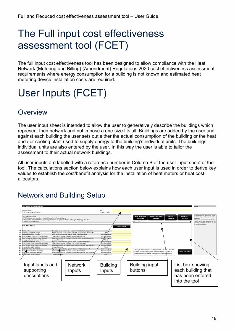
The user input sheet is intended to allow the user to generatively describe the buildings which represent their network and not impose a one-size fits all. Buildings are added by the user and against each building the user sets out either the actual consumption of the building or the heat and / or cooling plant used to supply energy to the building’s individual units. The buildings individual units are also entered by the user. In this way the user is able to tailor the assessment to their actual network buildings.
All user inputs are labelled with a reference number in Column B of the user input sheet of the tool. The calculations section below explains how each user input is used in order to derive key values to establish the cost/benefit analysis for the installation of heat meters or heat cost allocators.
Network and Building Setup
SECTION 1: NETWORK SET UP NOTES
1 Network name: text2 Network geographical location: dropdown option
BUILDING INPUTS:
A1 Building Name This is just for your reference - e.g. Town Hall, Central Library, Block A… textA2 Enter fuel costs for building? TRUE: enter fuel for the building (2A); FALSE: ener plant details (2B) T/FA3 Enter external wall U-Value? If you have calculated the specific U-Value for the building dropdown optionA4 External wall construction type - summary Selection from CIBSE standard wall construction types dropdown optionA5 External wall construction type - detailed Selection from CIBSE standard wall construction types (sub-selection) dropdown optionA6 Average external wall fabric efficiency U-value(If known) W/m2kA7 Enter external floor U-Value? If you have calculated the specific U-Value for the external floor dropdown optionA8 External floor construction type - summary Selection from CIBSE standard floor construction types dropdown optionA9 External floor construction type - Detailed Selection from CIBSE standard floor construction types (sub-selection) dropdown optionA10 Average floor fabric efficiency U-value(If known) W/m2kA11 Enter external roof U-Value? If you have calculated the specific U-Value for the external roof dropdown optionA12 Roof construction type - summary Selection from CIBSE standard roof construction types dropdown optionA13 Roof construction type - detailed Selection from CIBSE standard roof construction types (sub-selection) dropdown optionA14 Average roof fabric efficiency U-value(If known) W/m2k
1. Input building data as instructed. This will update the file and enable plant data to be added below.2. To amend details, select the building that needs amending using the adjacent text box, amend the data in the yellow boxes and click 'Amend Building Details'.
To add a new building:1. Add building name and other relevant information in the yellow boxes.2. Press 'ADD NEW BUILDING' - summary information will appear in the box to the right. This may take time.3. Repeat for each building.
ADD NEW NEW BUILDING
DELETE RECORD
AMEND BUILDING DETAILS
CLEAR FORM
DESELECTRECORD
COPY BUILDINGWhen you have created a building, its plant and units within the building you can then copy the building, its plant and units to allow for a quicker creation of a different building in the tool.
List box showing each building that has been entered into the tool
Network Inputs
Building Inputs
Building input buttons
Input labels and supporting descriptions
Full and Reduced cost effectiveness assessment tool – User Guide
19
Network Inputs
Network Name [1] (mandatory) The network name is a mandatory field and should be the unique identification number provided by the regulator or if this is not known a name that the user readily associates with the network (communal or district) that is being assessed. A building cannot be entered into the tool unless this field is populated.
Network geographical location [2] (mandatory) The network’s geographical location is a mandatory field and requires the user to select the region of the UK that the network is located in. In the unlikely event that a network spans across more than one UK region please select the region where majority of customers are located.
Network unique identification number [3] (optional) The network’s unique identification number is an optional field where the user can enter the networks unique identification number if they know it.
Building Inputs
Building Name [A1] (mandatory) This should be the name of one of the buildings that is to be assessed for the installation of either heat meters or heat cost allocators. For example, imagine a district heat network of 10 buildings is being assessed. Each of the 10 buildings would be entered into the tool (see “Add New Building” section below) and a separate name for each of the 10 buildings would be provided in this field upon entry of each building.
Enter fuel costs for building? [A2] (mandatory) The user can enter fuel bills relevant for heat/cooling supplied to or generated within each building entered into the tool. Fuel bills are entered in section 2 of the tool. If the user selects TRUE then the fuel cost(s) entered by the user in section 2A will be used in the economic appraisal. If FALSE is entered by the user then a derived fuel consumption and associated cost of fuel will be established by the tool based on the plant installed to deliver heat/cooling to the building entered in section 2B.
Enter external wall U-value [A3] (mandatory) If the user intends to enter his/her self-calculated U-Value for the external wall construction type, rather than rely on industry standards for the wall construction type, then the user should select “TRUE”. On selecting “TRUE” [A5] will no longer be hashed out and the user will be required to enter a U-Value. On selecting “FALSE” [A5] will remain hashed and the user need not make an entry.
External Wall Construction Type - summary [A4] (mandatory) The external wall construction type allows the user to select the type of external wall construction that is used in the building. Evidently different construction types and insulation used will impact the wall’s thermal conductivity (the extent to which heat will pass through it to the outside). This selection only impacts the calculation of heat/cooling demand in the event that the user does not specify the average U-value for the building’s external wall ([A5]).

Full and Reduced cost effectiveness assessment tool – User Guide
20
This is a mandatory field, even when a self-calculated U-Value for external wall is being provided. This is because we reserve the right to compare the U-Value provided to the industry benchmark for the External Wall Construction type selected.
The list of External Wall Construction types corresponds to CIBSE Guide A, Table 3.48 (2019):
Fuel type
1. Stone walls
2. No fines concrete walls
3. Solid brick walls
4. Dense concrete walls
5. Precast concrete panel walls
6. Brick/brick cavity walls
7. Brick/dense concrete block cavity walls
8. Brick/lightweight aggregate concrete block cavity walls
9. Brick/autoclaved aerated concrete block cavity walls
10. Timber frame walls
External wall construction type - detailed [A5] The dropdown list for [A4] is only populated when the user makes a selection for the summary external wall type. The detailed sub-list for each summary external wall construction type with accompanying U-Values and wall thicknesses can be found in Appendix 1: CIBSE.
Average external wall fabric efficiency [A6] The average external wall fabric efficiency or U-value reflects the W/m2K (Watt per meter squared Kelvin) thermal conductance of the external wall. The U-value provides the combined thermal conductivity of all the separate components of the external wall (e.g. brick, cavity, internal plaster etc.) as well as the convection of the internal and external surfaces.
It is not expected that all users will know the average U-value for a given building’s external walls. For this reason, industry average U-values are stored in the tool (refer to [A4]). Where a U-value is provided by the user, calculations for the U-value entered should be prepared and stored with completed tool in the event that the regulator requests evidence of the value used. For each building material used in the external wall, the K-value (thermal conductivity) should be sourced from either the original supplier or an equivalent supplier as supporting evidence for the U-value calculation. Internal and external surface resistance should be sourced from CIBSE Guide A.

Full and Reduced cost effectiveness assessment tool – User Guide
21
Enter external floor U-value [A7] (mandatory) If the user intends to enter his/her self-calculated U-Value for the external floor construction type, rather than rely on industry standards for the floor construction type, then the user should select “TRUE”. On selecting “TRUE” [A9] will no longer be hashed out and the user will be required to enter a U-Value. On selecting “FALSE” [A9] will remain hashed and the user need not make an entry.
External floor construction type - summary [A8] (mandatory) The external floor construction type allows the user to select the type of floor construction that is used in the building where it is in contact with the ground. Evidently different construction types and insulation used will impact the floor’s thermal conductivity (the extent to which heat will pass through it to the outside). This selection only impacts the calculation of heat/cooling demand in the event that the user does not specify the average U-value for the building’s floor that is in contact with the ground ([A9]).
This is a mandatory field, even when a self-calculated U-Value for the external floor is being provided. This is because we reserve the right to compare the U-Value provided to the industry benchmark for the external floor construction type selected.
The list of external floor construction types corresponds to CIBSE Guide A, Tables 3.52 – 3.54 (2019):
Fuel type
1. Ground contact solid concrete floors
2. Ground contact suspended timber floors
3. Outside air contact floors
External floor construction type - detailed [A9] The dropdown list for [A8] is only populated when the user makes a selection for the summary external floor type. The detailed sub-list for each summary external floor construction type with accompanying U-Values can be found in Appendix 1: CIBSE.
Average floor fabric efficiency [A10] The average external floor fabric efficiency or U-value reflects the W/m2K (Watt per meter squared Kelvin) thermal conductance of the building’s floors that are in contact with the ground. The U-value provides the combined thermal conductivity of all the separate components of the external floor (e.g. carpet, floor boards, air cavity, concrete etc.) as well as the convection of the internal and external surfaces (where appropriate).
It is not expected that all users will know the average U-value for a given building’s floors. For this reason, industry average U-values are stored in the tool. Where a U-value is provided by the user, calculations for the U-value entered should be prepared and stored with completed tool in the event that the regulator requests evidence of the value used. For each building material used in the external floor, the K-value (thermal conductivity) should be sourced from either the original supplier or an equivalent supplier as supporting evidence for the U-value calculation.
Full and Reduced cost effectiveness assessment tool – User Guide
22
Enter external floor U-value [A11] (mandatory) If the user intends to enter his/her self-calculated U-Value for the external roof construction type, rather than rely on industry standards for the roof construction type, then the user should select “TRUE”. On selecting “TRUE” [A13] will no longer be hashed out and the user will be required to enter a U-Value. On selecting “FALSE” [A13] will remain hashed and the user need not make an entry.
Roof construction type – summary [A12] (mandatory) The roof construction type allows the user to select the type of roof construction that is used in the building. Evidently different construction types and insulation used will impact the roof’s thermal conductivity (the extent to which heat will pass through it to the outside). This selection only impacts the calculation of heat/cooling demand in the event that the user does not specify the average U-value for the building’s roof ([A8]).
This is a mandatory field, even when a self-calculated U-Value for the external roof is being provided. This is because we reserve the right to compare the U-Value provided to the industry benchmark for the external roof construction type selected.
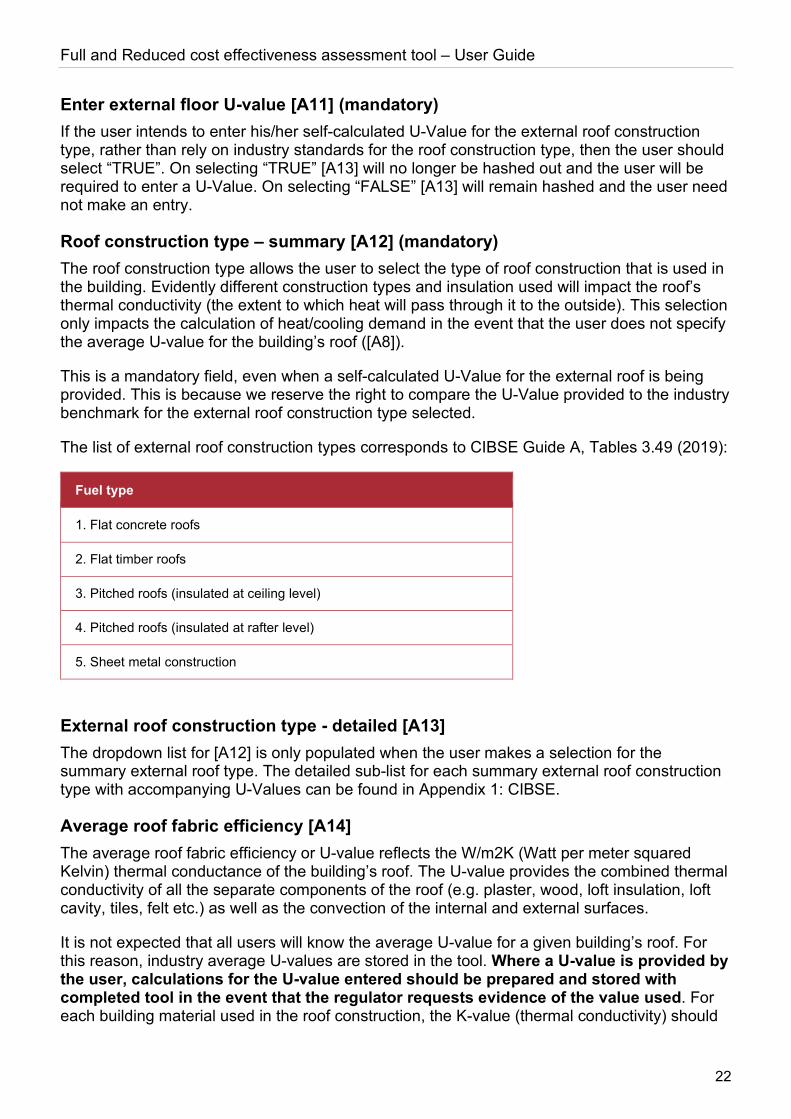
The list of external roof construction types corresponds to CIBSE Guide A, Tables 3.49 (2019):
Fuel type
1. Flat concrete roofs
2. Flat timber roofs
3. Pitched roofs (insulated at ceiling level)
4. Pitched roofs (insulated at rafter level)
5. Sheet metal construction
External roof construction type - detailed [A13] The dropdown list for [A12] is only populated when the user makes a selection for the summary external roof type. The detailed sub-list for each summary external roof construction type with accompanying U-Values can be found in Appendix 1: CIBSE.
Average roof fabric efficiency [A14] The average roof fabric efficiency or U-value reflects the W/m2K (Watt per meter squared Kelvin) thermal conductance of the building’s roof. The U-value provides the combined thermal conductivity of all the separate components of the roof (e.g. plaster, wood, loft insulation, loft cavity, tiles, felt etc.) as well as the convection of the internal and external surfaces.
It is not expected that all users will know the average U-value for a given building’s roof. For this reason, industry average U-values are stored in the tool. Where a U-value is provided by the user, calculations for the U-value entered should be prepared and stored with completed tool in the event that the regulator requests evidence of the value used. For each building material used in the roof construction, the K-value (thermal conductivity) should
Full and Reduced cost effectiveness assessment tool – User Guide
23
be sourced from either the original supplier or an equivalent supplier as supporting evidence for the U-value calculation.
Building Input Buttons
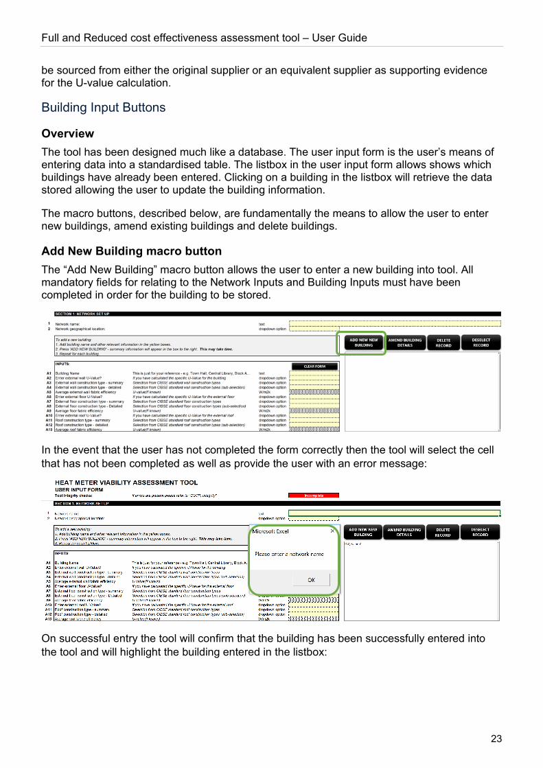
Overview The tool has been designed much like a database. The user input form is the user’s means of entering data into a standardised table. The listbox in the user input form allows shows which buildings have already been entered. Clicking on a building in the listbox will retrieve the data stored allowing the user to update the building information.
The macro buttons, described below, are fundamentally the means to allow the user to enter new buildings, amend existing buildings and delete buildings.
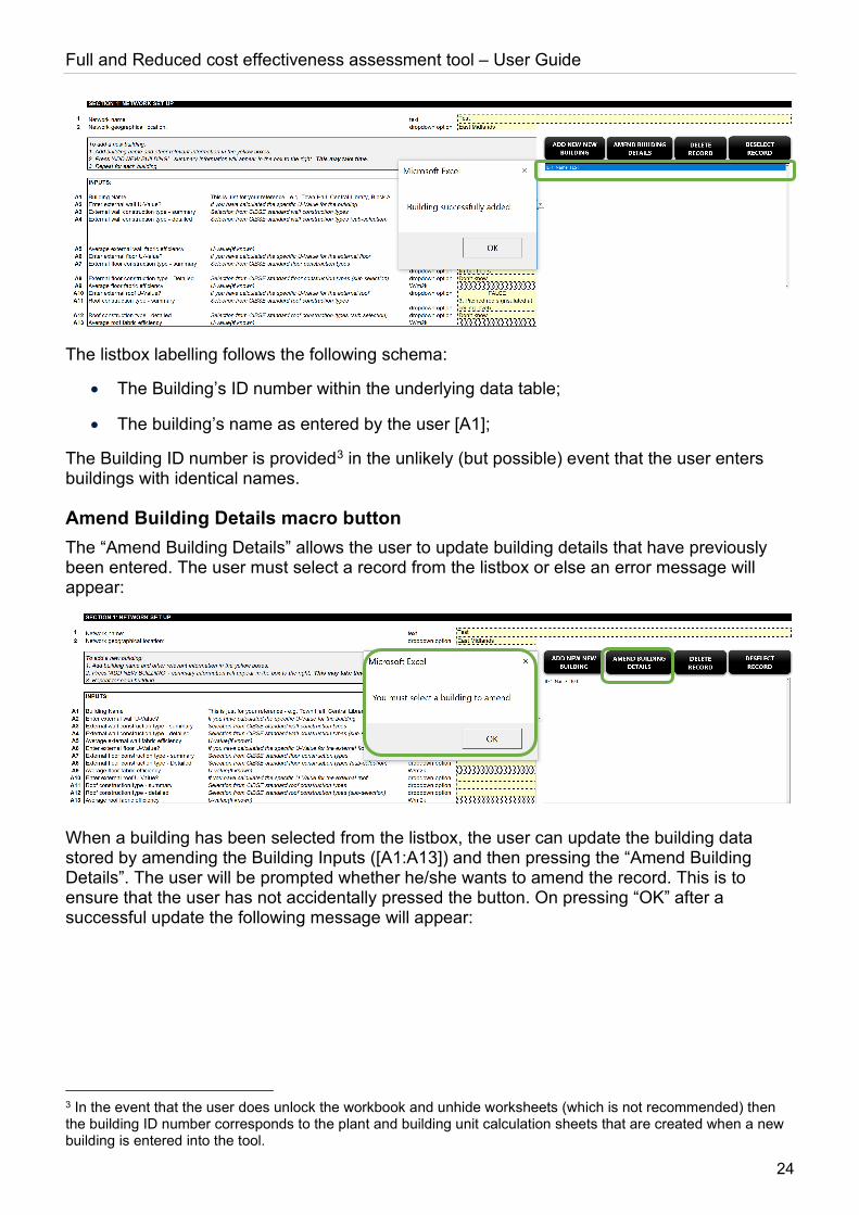
Add New Building macro button The “Add New Building” macro button allows the user to enter a new building into tool. All mandatory fields for relating to the Network Inputs and Building Inputs must have been completed in order for the building to be stored.
In the event that the user has not completed the form correctly then the tool will select the cell that has not been completed as well as provide the user with an error message:
On successful entry the tool will confirm that the building has been successfully entered into the tool and will highlight the building entered in the listbox:
Full and Reduced cost effectiveness assessment tool – User Guide
24
The listbox labelling follows the following schema:
• The Building’s ID number within the underlying data table;
• The building’s name as entered by the user [A1];
The Building ID number is provided3 in the unlikely (but possible) event that the user enters buildings with identical names.
Amend Building Details macro button The “Amend Building Details” allows the user to update building details that have previously been entered. The user must select a record from the listbox or else an error message will appear:
When a building has been selected from the listbox, the user can update the building data stored by amending the Building Inputs ([A1:A13]) and then pressing the “Amend Building Details”. The user will be prompted whether he/she wants to amend the record. This is to ensure that the user has not accidentally pressed the button. On pressing “OK” after a successful update the following message will appear:
3 In the event that the user does unlock the workbook and unhide worksheets (which is not recommended) then the building ID number corresponds to the plant and building unit calculation sheets that are created when a new building is entered into the tool.

Full and Reduced cost effectiveness assessment tool – User Guide
25
Delete Record macro button The “Delete Record” macro button allows the user to delete a building stored within the tool. As with the amend record button a building must be selected in the listbox or else an error message will appear.
The user will be asked to confirm that he/she does want to delete the record. On pressing “OK” the building will be deleted from the tool. It should be noted that any plant items and any building units stored in the tool that are attributed to the building being deleted will also be deleted from the tool. As such deletions should only be made if the user is absolutely sure. It is recommended to store the tool as a separate instance of the tool just in case it is subsequently decided that the deletion should not have been made.
Deselect Record macro button The “Deselect Record” macro button allows the user to first recall a building already stored in the tool and then subsequently deselect it from the listbox whilst retaining the building data in the Building Inputs section. This is useful where a new building with similar characteristics as another building is to be entered into the tool. The user will recall that the “Add New Building” macro button will not allow the user to enter a new building when a building is already selected in the listbox.
Clear Form macro button The “Clear Form” macro button allows the user to clear the Building Inputs allowing the user to start again. Any data that has not been stored (either via the Add New Building or Amend Existing Building macro buttons) will be lost. A prompt will appear asking the user to confirm they want to clear the form. On pressing “OK” all entries will be cleared but no records will be deleted in the tool’s underlying data table for buildings.
Full and Reduced cost effectiveness assessment tool – User Guide
26
Fuel Consumption
Fuel Inputs
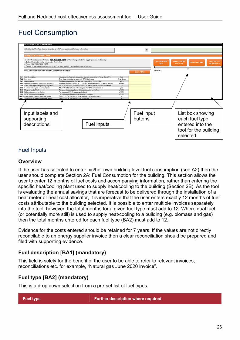
Overview If the user has selected to enter his/her own building level fuel consumption (see A2) then the user should complete Section 2A: Fuel Consumption for the building. This section allows the user to enter 12 months of fuel costs and accompanying information, rather than entering the specific heat/cooling plant used to supply heat/cooling to the building (Section 2B). As the tool is evaluating the annual savings that are forecast to be delivered through the installation of a heat meter or heat cost allocator, it is imperative that the user enters exactly 12 months of fuel costs attributable to the building selected. It is possible to enter multiple invoices separately into the tool; however, the total months for a given fuel type must add to 12. Where dual fuel (or potentially more still) is used to supply heat/cooling to a building (e.g. biomass and gas) then the total months entered for each fuel type (BA2) must add to 12.
Evidence for the costs entered should be retained for 7 years. If the values are not directly reconcilable to an energy supplier invoice then a clear reconciliation should be prepared and filed with supporting evidence.
Fuel description [BA1] (mandatory) This field is solely for the benefit of the user to be able to refer to relevant invoices, reconciliations etc. for example, “Natural gas June 2020 invoice”.
Fuel type [BA2] (mandatory) This is a drop down selection from a pre-set list of fuel types:
Fuel type Further description where required
SECTION 2A: FUEL CONSUMPTION
ADD PLANT & EQUIPMENT DATA
FUEL CONSUMPTION FOR THE BUILDING OVER THE YEAR
BA1 Fuel description You can enter free text to describe the fuel being entered (e.g. Gas-INV1) textBA2 Fuel type Drop down selection to align with BEIS fuel types Drop downBA3 Consumption The fuel consumed in line with the invoice from the supplier kWhBA4 Number of months consumption relates to # months that BA3 relates to - total for a given fuel must = 12 across entries monthsBA5 Is the consumption degree day adjusted? Have you adjusted your consumption to reflect annual weather variation? T/FBA6 If not adjusted: year of consumption If BA5=FALSE: please enter the year that BA3 corresponds to yearBA7 Marginal cost of fuel The cost of each additional kWh consumption of the fuel p/kWhBA8 Relevant consumption levies For example CCL for gas and electricity p/kWhBA9 Other consumption charges For example distribution use of system charges p/kWhBA10 Fixed charge over consumption period This should be the fixed charge over the consumption period £BA11 Total fuel cost over consumption period This should be the total annual cost of the fuel £
Select the building from the drop down list for which you want to add fuel cost information
To add information on the fuel cost FOR A SINGLE YEAR of the building selected to supply/generate heat/cooling:1. Enter details in the yellow boxes in the form below2. Press 'ADD NEW FUEL ITEM'3. Repeat for each additional fuel type (n.b. if you have multiple invoices for the same fuel type
ADD NEW FUELITEM
CLEAR FORM
AMEND EXISTINGFUEL ITEM DELETE EXISTING DESELECT FUEL
FROM LISTBOX
List box showing each fuel type entered into the tool for the building selected
Fuel Inputs
Fuel input buttons
Input labels and supporting descriptions
Full and Reduced cost effectiveness assessment tool – User Guide
27
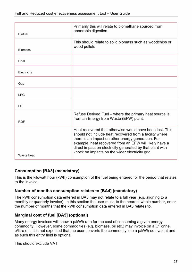
Biofuel
Primarily this will relate to biomethane sourced from anaerobic digestion.
Biomass
This should relate to solid biomass such as woodchips or wood pellets
Coal
Electricity
Gas
LPG
Oil
RDF
Refuse Derived Fuel – where the primary heat source is from an Energy from Waste (EFW) plant.
Waste heat
Heat recovered that otherwise would have been lost. This should not include heat recovered from a facility where there is an impact on other energy generation. For example, heat recovered from an EFW will likely have a direct impact on electricity generated by that plant with knock on impacts on the wider electricity grid.
Consumption [BA3] (mandatory) This is the kilowatt hour (kWh) consumption of the fuel being entered for the period that relates to the invoice.
Number of months consumption relates to [BA4] (mandatory) The kWh consumption data entered in BA3 may not relate to a full year (e.g. aligning to a monthly or quarterly invoice). In this section the user must, to the nearest whole number, enter the number of months that the kWh consumption data entered in BA3 relates to.
Marginal cost of fuel [BA5] (optional) Many energy invoices will show a p/kWh rate for the cost of consuming a given energy commodity. However, some commodities (e.g. biomass, oil etc.) may invoice on a £/Tonne, p/litre etc. It is not expected that the user converts the commodity into a p/kWh equivalent and as such this entry field is optional.
This should exclude VAT.
Full and Reduced cost effectiveness assessment tool – User Guide
28
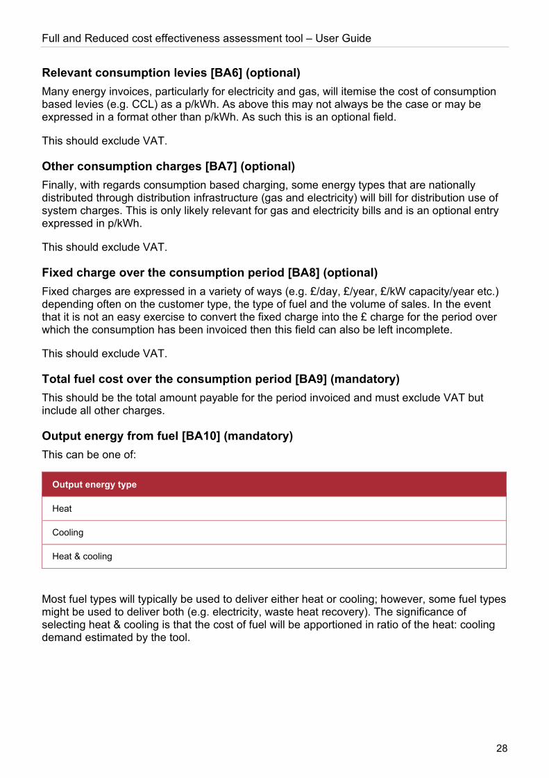
Relevant consumption levies [BA6] (optional) Many energy invoices, particularly for electricity and gas, will itemise the cost of consumption based levies (e.g. CCL) as a p/kWh. As above this may not always be the case or may be expressed in a format other than p/kWh. As such this is an optional field.
This should exclude VAT.
Other consumption charges [BA7] (optional) Finally, with regards consumption based charging, some energy types that are nationally distributed through distribution infrastructure (gas and electricity) will bill for distribution use of system charges. This is only likely relevant for gas and electricity bills and is an optional entry expressed in p/kWh.
This should exclude VAT.
Fixed charge over the consumption period [BA8] (optional) Fixed charges are expressed in a variety of ways (e.g. £/day, £/year, £/kW capacity/year etc.) depending often on the customer type, the type of fuel and the volume of sales. In the event that it is not an easy exercise to convert the fixed charge into the £ charge for the period over which the consumption has been invoiced then this field can also be left incomplete.
This should exclude VAT.
Total fuel cost over the consumption period [BA9] (mandatory) This should be the total amount payable for the period invoiced and must exclude VAT but include all other charges.
Output energy from fuel [BA10] (mandatory) This can be one of:
Output energy type
Heat
Cooling
Heat & cooling
Most fuel types will typically be used to deliver either heat or cooling; however, some fuel types might be used to deliver both (e.g. electricity, waste heat recovery). The significance of selecting heat & cooling is that the cost of fuel will be apportioned in ratio of the heat: cooling demand estimated by the tool.
Full and Reduced cost effectiveness assessment tool – User Guide
29
Heat generating plant within or outside the building
Plant Inputs
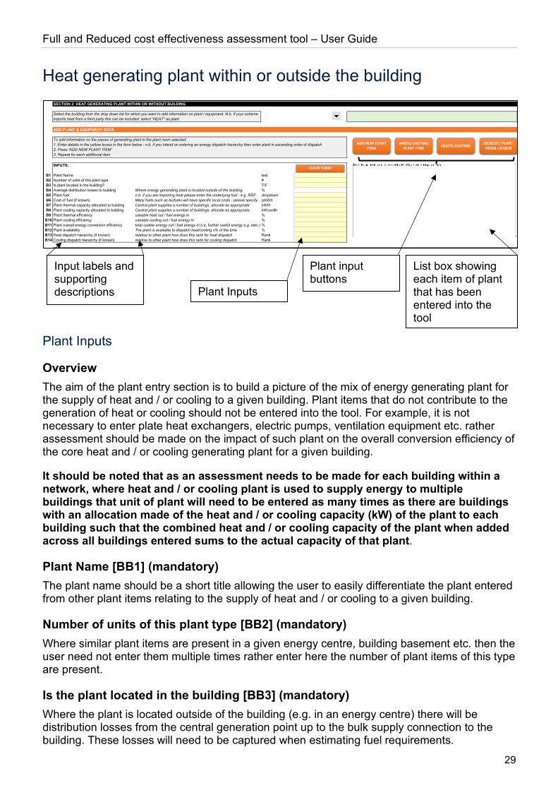
Overview The aim of the plant entry section is to build a picture of the mix of energy generating plant for the supply of heat and / or cooling to a given building. Plant items that do not contribute to the generation of heat or cooling should not be entered into the tool. For example, it is not necessary to enter plate heat exchangers, electric pumps, ventilation equipment etc. rather assessment should be made on the impact of such plant on the overall conversion efficiency of the core heat and / or cooling generating plant for a given building.
It should be noted that as an assessment needs to be made for each building within a network, where heat and / or cooling plant is used to supply energy to multiple buildings that unit of plant will need to be entered as many times as there are buildings with an allocation made of the heat and / or cooling capacity (kW) of the plant to each building such that the combined heat and / or cooling capacity of the plant when added across all buildings entered sums to the actual capacity of that plant.
Plant Name [BB1] (mandatory) The plant name should be a short title allowing the user to easily differentiate the plant entered from other plant items relating to the supply of heat and / or cooling to a given building.
Number of units of this plant type [BB2] (mandatory) Where similar plant items are present in a given energy centre, building basement etc. then the user need not enter them multiple times rather enter here the number of plant items of this type are present.
Is the plant located in the building [BB3] (mandatory) Where the plant is located outside of the building (e.g. in an energy centre) there will be distribution losses from the central generation point up to the bulk supply connection to the building. These losses will need to be captured when estimating fuel requirements.
SECTION 2: HEAT GENERATING PLANT WITHIN OR WITHOUT BUILDING
ADD PLANT & EQUIPMENT DATA
INPUTS:
B1 Plant Name textB2 Number of units of this plant type #B3 Is plant located in the building? T/FB4 Average distribution losses to building Where energy generating plant is located outside of the building %B5 Plant fuel n.b. if you are importing heat please enter the underlying fuel - e.g. RDF dropdownB6 Cost of fuel (if known) Many fuels such as biofuels will have specific local costs - please specify p/kWhB7 Plant thermal capacity allocated to building Central plant supplies a number of buildings: allocate as appropriate kWthB8 Plant cooling capacity allocated to building Central plant supplies a number of buildings: allocate as appropriate kWcoolthB9 Plant thermal efficiency useable heat out / fuel energy in %B10 Plant cooling efficiency useable cooling out / fuel energy in %B11 Plant overall energy conversion efficiency total usable energy out / fuel energy in (i.e. further useful energy e.g. elec.) %B12 Plant availability The plant is available to dispatch heat/cooling x% of the time %B13 Heat dispatch hierarchy (if known) relative to other plant how does this rank for heat dispatch RankB14 Cooling dispatch hierarchy (if known) relative to other plant how does this rank for cooling dispatch Rank
To add information on the pieces of generating plant in the plant room selected:1. Enter details in the yellow boxes in the form below - n.b. if you intend on entering an energy dispatch hierarchy then enter plant in ascending order of dispatch2. Press 'ADD NEW PLANT ITEM'3. Repeat for each additional item
Select the building from the drop down list for which you want to add information on plant / equipment. N.b. if your scheme imports heat from a third party this can be included: select "HEAT" as plant
ADD NEW PLANT ITEM
CLEAR FORM
AMEND EXISTINGPLANT ITEM DELETE EXISTING DESELECT PLANT
FROM LISTBOX
List box showing each item of plant that has been entered into the tool
Plant Inputs
Plant input buttons
Input labels and supporting descriptions
Full and Reduced cost effectiveness assessment tool – User Guide
30
Average distribution losses to end customers [BB4] (mandatory if BB3 is set to FALSE) When plant is located outside of the building it is necessary to include the distribution losses that will arise on supplying heat / cooling from the central point to the individual Heat Interface Units within the building being supplied. The percentage entered should be a percentage loss of supply not of demand. For example, if heat losses across a distribution network to end customers are estimated to be 5% this should reflect 5% of the supply into that network not 5% of the demand from that network.
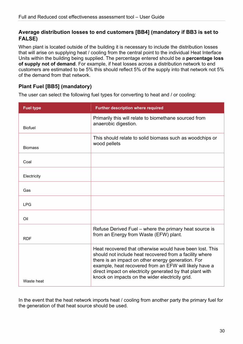
Plant Fuel [BB5] (mandatory) The user can select the following fuel types for converting to heat and / or cooling:
Fuel type Further description where required
Biofuel
Primarily this will relate to biomethane sourced from anaerobic digestion.
Biomass
This should relate to solid biomass such as woodchips or wood pellets
Coal
Electricity
Gas
LPG
Oil
RDF
Refuse Derived Fuel – where the primary heat source is from an Energy from Waste (EFW) plant.
Waste heat
Heat recovered that otherwise would have been lost. This should not include heat recovered from a facility where there is an impact on other energy generation. For example, heat recovered from an EFW will likely have a direct impact on electricity generated by that plant with knock on impacts on the wider electricity grid.
In the event that the heat network imports heat / cooling from another party the primary fuel for the generation of that heat source should be used.
Full and Reduced cost effectiveness assessment tool – User Guide
31
Cost of fuel [BB6] (mandatory if not a BEIS published commodity type) For fuels other than Coal, Electricity, Gas and Oil the user must enter a p/kWh cost of that fuel. Where there is both a fixed and variable charge associated with the fuel the user should convert the fixed charge into a p/kWh value. This can be done by taking the average annual fuel consumption (kWh) and divide the total annual cost (expressed in pence) by this value. This can then be added to the variable (p/kWh) charge of the fuel type.
If the fuel type consumption is quoted in units other than kWh then the most recent published conversion rates should be used4.
Plant thermal capacity allocated to building [BB7] (mandatory) The thermal capacity allocated to the building should reflect the kWth capacity of the plant that is available for the building that has been selected. For example, if a gas boiler of 10,000kWth is peaking plant for heat supply to 10 buildings of equal size then the allocation might be 1,000kWth entered on the basis of 1/10 allocation. Another method may be to add the estimated diversified peak heating demand of each customer within a given building to establish the capacity allocation to fthat building.
The sum of capacities allocated across different buildings must not exceed the plant’s actual heat generating capacity.
Where the plant supplies only cooling the value entered should be 0.
Plant cooling capacity allocated to building [BB8] (mandatory) The cooling capacity allocated to the building should reflect the kWcoolth capacity of the plant that is available for the building that has been selected. For example, if an electric chiller 10,000kWcoolth is supplying cooling to 10 buildings of equal size then the allocation might be 1,000kWcoolth entered on the basis of 1/10 allocation. Another method may be to add the estimated diversified peak cooling demand of each customer within a given building to establish the capacity allocation to that building.
The sum of capacities allocated across different buildings must not exceed the plant’s actual cooling generating capacity.
Where the plant supplies only heating the value entered should be 0.
Plant thermal efficiency [BB9] (mandatory) The plant’s thermal efficiency should reflect the heat capacity (kWth) out divided by the fuel supplied to the plant (kW) to enable that capacity output. For example, if a Combined Heat and Power (CHP) engine has a thermal capacity of 1,000kWth and has a total gas fuel requirement of 2,325kW then the thermal efficiency entered would be 43% (1000/2325).
If no heat is being supplied then enter 0%.
Plant cooling efficiency [BB10] (mandatory) The plant’s cooling efficiency should reflect the cooling capacity (kWcoolth) out divided by the fuel supplied to the plant (kW) to enable that capacity output. For example, if an electric chiller
4 Government emission conversion factors for greenhouse gas company reporting: https://www.gov.uk/government/collections/government-conversion-factors-for-company-reporting
Full and Reduced cost effectiveness assessment tool – User Guide
32
has a cooling capacity of 1,000kWcoolth and has a total electricity input requirement of 222kW then the thermal efficiency entered would be 450% (1000/222).
If no cooling is being supplied then enter 0%.
Plant overall energy conversion efficiency [BB11] (mandatory) The overall energy conversion efficiency reflects the possibility that the plant may be generating useful energy other than heat or cooling. Namely this will be electricity. For example, a CHP may have a thermal efficiency of 43% but an overall conversion efficiency of 82% when taking both heat and electricity into account.
The overall energy conversion efficiency should typically be the same as the sum of the cooling and heating efficiencies but it should never be less.
Plant availability [BB12] (mandatory) The plant availability reflects the % of total hours in the year that the plant is able to operate at its stated capacity. For example, if the plant will only operate over the winter period then the availability entered would be the number of hours in the winter when it may supply heat divided by the total number of hours in the year (8760).
Heat dispatch hierarchy (if known) [BB13] The heat dispatch hierarchy reflects the relative order of dispatch of heat. For example, if a heat network has a watersource heat pump (WSHP), a small gas CHP engine and a back-up gas boiler the dispatch hierarchy may be that the WSHP will be the primary supply of heat to the extent that it is available, the CHP as the secondary plant and the gas boiler held in reserve (third).
If the dispatch hierarchy is not known then this can be left blank and the tool will determine the dispatch hierarchy (see calculations section).
Values entered must be sequential starting from 1. As such, using the example above, if the user were to first enter the gas boiler it would not be possible to enter 3 as 1 & 2 would not have been entered into the tool at that point. The user would need to store the gas boiler leaving the heat dispatch hierarchy blank. When all other plant items had been added then the gas boiler’s dispatch hierarchy could be updated to 3.
In the event that a plant item is deleted and the plant item has a dispatch hierarchy lower than the plant item deleted then the tool will automatically adjust the hierarchy down by 1. Taking the example above, were the CHP engine deleted from the tool the gas boiler’s heat dispatch hierarchy would be adjusted down to 2.
Cooling dispatch hierarchy (if known) [BB14] This is exactly the same logic as for heat dispatch (see section above) only with regards the dispatch of cooling.
It should be noted that cooling dispatch and heating dispatch are treated completely separately within the tool.
Full and Reduced cost effectiveness assessment tool – User Guide
33
Plant input buttons
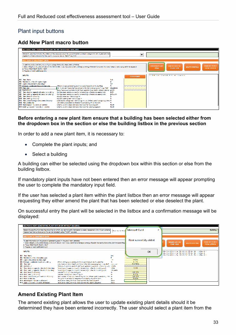
Add New Plant macro button
Before entering a new plant item ensure that a building has been selected either from the dropdown box in the section or else the building listbox in the previous section
In order to add a new plant item, it is necessary to:
• Complete the plant inputs; and
• Select a building
A building can either be selected using the dropdown box within this section or else from the building listbox.
If mandatory plant inputs have not been entered then an error message will appear prompting the user to complete the mandatory input field.
If the user has selected a plant item within the plant listbox then an error message will appear requesting they either amend the plant that has been selected or else deselect the plant.
On successful entry the plant will be selected in the listbox and a confirmation message will be displayed:
Amend Existing Plant Item The amend existing plant allows the user to update existing plant details should it be determined they have been entered incorrectly. The user should select a plant item from the
Full and Reduced cost effectiveness assessment tool – User Guide
34
listbox, make the update in the plant inputs section and then press the “Amend Existing Plant Item” button.
Delete Existing Plant Item To delete an item of plant that has been entered into the tool, the user should select the plant item from the plant listbox and then press “Delete Existing”. The user will be asked to confirm that he/she wants to delete the plant item. On pressing “OK” the plant item will be deleted from the tool.
Deselect Record macro button The “Deselect Record” macro button allows the user to first recall a plant item already stored in the tool and then subsequently deselect it from the listbox whilst retaining the plant item data in the Plant Inputs section. This is useful where a new plant item with similar characteristics as another plant item is to be entered into the tool.
Clear Form macro button The “Clear Form” macro button allows the user to clear the Plant Inputs allowing the user to start again. Any data that has not been stored (either via the Add New Plant or Amend Existing Plant macro buttons) will be lost. A prompt will appear asking the user to confirm they want to clear the form. On pressing “OK” all entries will be cleared but no records will be deleted in the tool’s underlying data table for plant items.
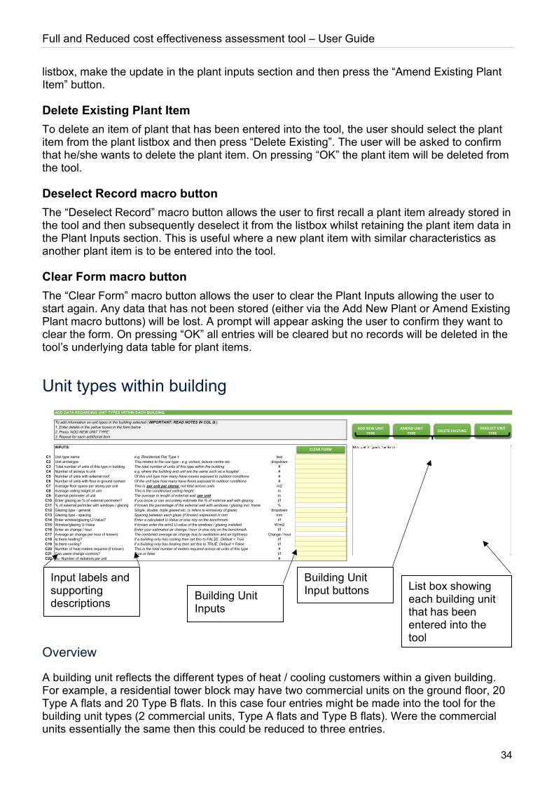
Unit types within building
Overview
A building unit reflects the different types of heat / cooling customers within a given building. For example, a residential tower block may have two commercial units on the ground floor, 20 Type A flats and 20 Type B flats. In this case four entries might be made into the tool for the building unit types (2 commercial units, Type A flats and Type B flats). Were the commercial units essentially the same then this could be reduced to three entries.
ADD DATA REGARDING UNIT TYPES WITHIN EACH BUILDING
INPUTS:
C1 Unit type name e.g. Residential Flat Type 1 textC2 Unit archetype This relates to the use type - e.g. school, leisure centre etc. dropdownC3 Total number of units of this type in building The total number of units of this type within the building #C4 Number of storeys in unit e.g. where the building and unit are the same such as a hospital #C5 Number of units with external roof Of this unit type how many have rooves exposed to outdoor conditions #C6 Number of units with floor in ground contact Of the unit type how many have floors exposed to outdoor conditions #C7 Average floor space per storey per unit This is per unit per storey not total across units m2C8 Average ceiling height of unit This is the conditioned ceiling height mC9 External perimeter of unit The average m length of external wall per unit mC10 Enter glazing as % of external perimeter? If you know or can accurately estimate the % of external wall with glazing t/fC11 % of external perimiter with windows / glazing If known the percentage of the external wall with windows / glazing incl. frame %C12 Glazing type - general Single, double, triple glazed etc. (ε refers to emissivity of glaze) dropdownC13 Glazing type - spacing Spacing between each glaze (if known) expressed in mm mmC14 Enter window/glazing U-Value? Enter a calculated U-Value or else rely on the benchmark t/fC15 Window/glazing U-Value If known enter the w/m2 U-value of the windows / glazing installed W/m2C16 Enter air change / hour Enter your estimated air change / hour or else rely on the benchmark t/fC17 Average air change per hour (if known) The combined average air change due to ventilation and air tightness Change / hourC18 Is there heating? If a building only has cooling then set this to FALSE. Default = True t/fC19 Is there cooling? If a building only has heating then set this to TRUE. Default = False t/fC20 Number of heat meters required (if known) This is the total number of meters required across all units of this type #C21 Can users change controls? True or false t/fC22 Av. Number of radiators per unit #
To add information on unit types in the building selected ( IMPORTANT: READ NOTES IN COL Q ):1. Enter details in the yellow boxes in the form below2. Press 'ADD NEW UNIT TYPE'3. Repeat for each additional item
ADD NEW UNIT TYPE
CLEAR FORM
AMEND UNIT TYPE DELETE EXISTING
DESELECT UNIT TYPE
List box showing each building unit that has been entered into the tool
Building Unit Inputs
Building Unit Input buttons
Input labels and supporting descriptions
Full and Reduced cost effectiveness assessment tool – User Guide
35
Building Unit Inputs
Unit type name [C1] (mandatory) The unit type name should be a title that is understood by the user to identify the unit or units being appraised. For example, this could be a flat type (e.g. Type 1A) or it could be a commercial unit (e.g. Commercial Unit 1), or any other collection of occupied spaces with similar characteristics. A key objective is to consolidate as many building units into a single entry such that it does not require the user to enter every single connected customer’s individual occupied space.
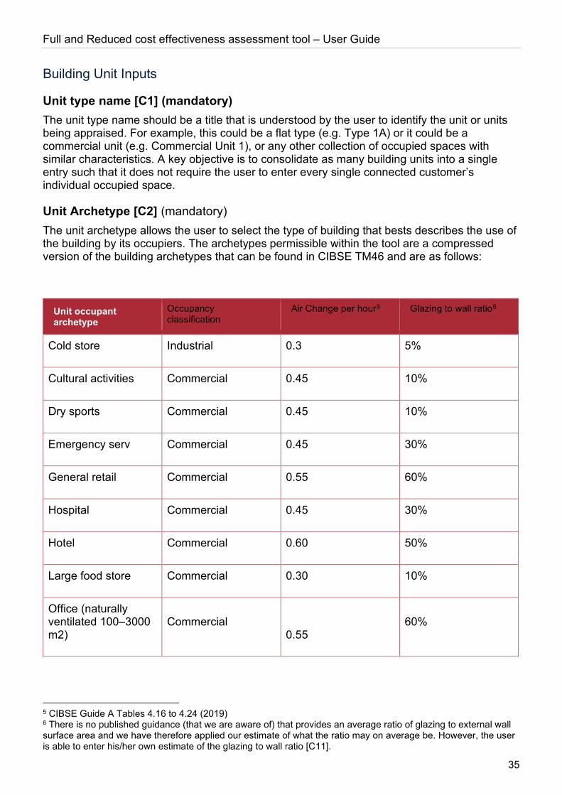
Unit Archetype [C2] (mandatory) The unit archetype allows the user to select the type of building that bests describes the use of the building by its occupiers. The archetypes permissible within the tool are a compressed version of the building archetypes that can be found in CIBSE TM46 and are as follows:
Unit occupant archetype
Occupancy classification
Air Change per hour5 Glazing to wall ratio6
Cold store Industrial 0.3 5%
Cultural activities Commercial 0.45 10%
Dry sports Commercial 0.45 10%
Emergency serv Commercial 0.45 30%
General retail Commercial 0.55 60%
Hospital Commercial 0.45 30%
Hotel Commercial 0.60 50%
Large food store Commercial 0.30 10%
Office (naturally ventilated 100–3000 m2)
Commercial 0.55
60%
5 CIBSE Guide A Tables 4.16 to 4.24 (2019) 6 There is no published guidance (that we are aware of) that provides an average ratio of glazing to external wall surface area and we have therefore applied our estimate of what the ratio may on average be. However, the user is able to enter his/her own estimate of the glazing to wall ratio [C11].
Full and Reduced cost effectiveness assessment tool – User Guide
36
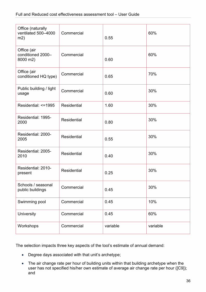
Office (naturally ventilated 500–4000 m2)
Commercial 0.55
60%
Office (air conditioned 2000–8000 m2)
Commercial 0.60
60%
Office (air conditioned HQ type) Commercial 0.65 70%
Public building / light usage Commercial 0.60 30%
Residential: <=1995 Residential 1.60 30%
Residential: 1995-2000 Residential 0.80 30%
Residential: 2000-2005 Residential 0.55 30%
Residential: 2005-2010 Residential 0.40 30%
Residential: 2010-present Residential 0.25 30%
Schools / seasonal public buildings Commercial 0.45 30%
Swimming pool Commercial 0.45 10%
University Commercial 0.45 60%
Workshops Commercial variable variable
The selection impacts three key aspects of the tool’s estimate of annual demand:
• Degree days associated with that unit’s archetype;
• The air change rate per hour of building units within that building archetype when the user has not specified his/her own estimate of average air change rate per hour ([C9]); and
Full and Reduced cost effectiveness assessment tool – User Guide
37
• The glazing to wall ratio in the event that the user has not specified his/her own estimate of the average ratio of glazing to wall fabric ([C11])
Total number of units of this type in building [C3] (mandatory) Continuing the example presented in the overview above for the Type A flat the value entered would be 20. This is an important part of the section as it allows the user to avoid having to enter every single unit of a given type.
Number of storeys in unit [C4] (mandatory) Some units may be split across several floors. The user should enter the number of floors that a given unit covers.
Number of units with external roof [C5] (mandatory) Of the total number of units entered ([C3]) how many of these have external roofs? For example, if the block of flats was a high-rise then perhaps only 4 of the 20 units had external roofs. Alternatively, if the Building Units entered was a low rise block of flats then perhaps 10 of the Type A flats have external roofs.
This entry is important for the calculation of heat losses through roofs (see calculation section).
Number of units with floor in ground contact [C6] (mandatory) Of the total number of units entered ([C3]) how many of these have floors that are in contact with the ground? For example if the block of flats was a high-rise then perhaps only 2 of the 20 units had contact with the ground. Alternatively if the Building Units entered was a low rise block of flats then perhaps 10 of the Type A flats have ground contact.
This entry is important for the calculation of heat losses through floors (see calculation section).
Average floor space per storey per unit [C7] (mandatory) This is the average m2 floor space per storey of the building unit type being entered. Continuing the example, if the Type A flat typically had a floor space of 50m2 on a single storey then 50 would be entered. If there were two storeys then the user might enter 25m2 (2 x 25 = 50m2). What would not be entered would be 50 x 20 units.
Average ceiling height of unit [C8] (mandatory) The average ceiling height is the number of meters that the ceiling is above the floor for the building unit type being entered. For simplicity, the ceiling should be taken as the visible ceiling – i.e. the ceiling of the conditioned internal space. Where suspending ceilings are used it is not necessary to enter the cavity above the suspending ceiling.
External perimeter of unit [C9] (mandatory) The external wall length should be the average length, in meters, of wall that is in contact with outside conditions on a per unit per storey basis. Continuing with the example if the average Type A flat had total external walls of 8 meter length (the remaining walls being in contact with other flats and common parts) then 8 would be entered here. What would not be entered would be 8 x 20 units. If the unit was split over two storeys 8 would still be entered here.
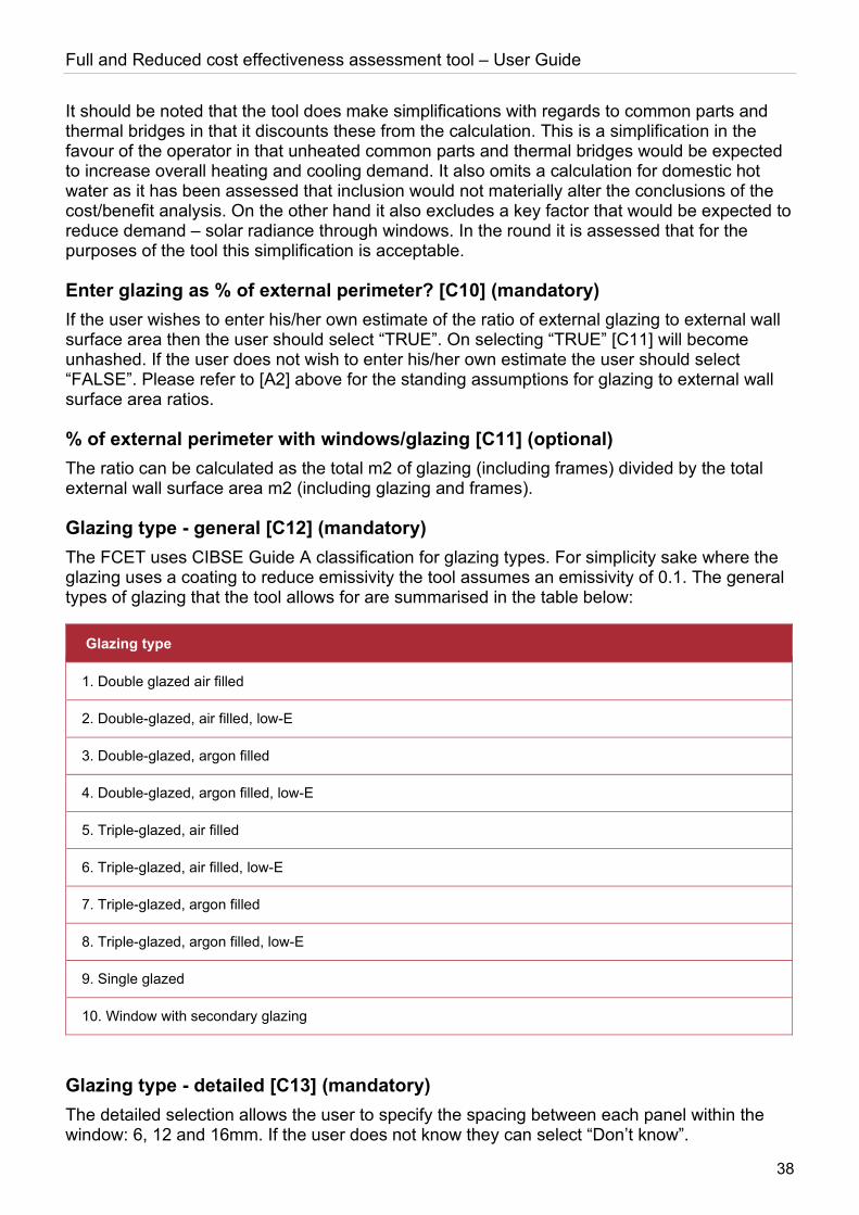
Full and Reduced cost effectiveness assessment tool – User Guide
38
It should be noted that the tool does make simplifications with regards to common parts and thermal bridges in that it discounts these from the calculation. This is a simplification in the favour of the operator in that unheated common parts and thermal bridges would be expected to increase overall heating and cooling demand. It also omits a calculation for domestic hot water as it has been assessed that inclusion would not materially alter the conclusions of the cost/benefit analysis. On the other hand it also excludes a key factor that would be expected to reduce demand – solar radiance through windows. In the round it is assessed that for the purposes of the tool this simplification is acceptable.
Enter glazing as % of external perimeter? [C10] (mandatory) If the user wishes to enter his/her own estimate of the ratio of external glazing to external wall surface area then the user should select “TRUE”. On selecting “TRUE” [C11] will become unhashed. If the user does not wish to enter his/her own estimate the user should select “FALSE”. Please refer to [A2] above for the standing assumptions for glazing to external wall surface area ratios.
% of external perimeter with windows/glazing [C11] (optional) The ratio can be calculated as the total m2 of glazing (including frames) divided by the total external wall surface area m2 (including glazing and frames).
Glazing type - general [C12] (mandatory) The FCET uses CIBSE Guide A classification for glazing types. For simplicity sake where the glazing uses a coating to reduce emissivity the tool assumes an emissivity of 0.1. The general types of glazing that the tool allows for are summarised in the table below:
Glazing type
1. Double glazed air filled
2. Double-glazed, air filled, low-E
3. Double-glazed, argon filled
4. Double-glazed, argon filled, low-E
5. Triple-glazed, air filled
6. Triple-glazed, air filled, low-E
7. Triple-glazed, argon filled
8. Triple-glazed, argon filled, low-E
9. Single glazed
10. Window with secondary glazing
Glazing type - detailed [C13] (mandatory) The detailed selection allows the user to specify the spacing between each panel within the window: 6, 12 and 16mm. If the user does not know they can select “Don’t know”.
Full and Reduced cost effectiveness assessment tool – User Guide
39
Appendix 1: CIBSE sets out the U-Values that are stored within the FCET from CIBSE Guide A Table 3.29 (2019). Where the user has calculated his/her own estimate of the U-Value of the glazing used in the building this can be entered manually [C15].
Enter window/glazing U-Value? [C14] (mandatory) If the user intends to enter his/her self-calculated U-Value for the glazing type, rather than rely on industry standards for the glazing construction type, then the user should select “TRUE”. On selecting “TRUE” [A15] will no longer be hashed out and the user will be required to enter a U-Value. On selecting “FALSE” [A15] will remain hashed and the user need not make an entry.
Window/glazing U-Value [A15] The average window glazing efficiency or U-value reflects the W/m2K (Watt per meter squared Kelvin) thermal conductance of the building’s glazing (including frames). The U-value provides the combined thermal conductivity of all the separate components of the window (e.g. each panel, the spacing between – argon filled, air filled etc.) as well as the convection of the internal and external surfaces.
It is not expected that all users will know the average U-value for a given building’s glazing. For this reason, industry average U-values are stored in the tool. Where a U-value is provided by the user, calculations for the U-value entered should be prepared and stored with completed tool in the event that the regulator requests evidence of the value used. For each building material used in the glazing’s construction, the K-value (thermal conductivity) should be sourced from either the original supplier or an equivalent supplier as supporting evidence for the U-value calculation.
Enter air change / hour? [C16] (mandatory) If the user intends to enter his/her self-calculated air change per hour for the unit type, rather than rely on industry standards for the unit archetype selected, then the user should select “TRUE”. On selecting “TRUE” [A17] will no longer be hashed out and the user will be required to enter an air change per hour assumption. On selecting “FALSE” [A17] will remain hashed and the user need not make an entry.
Average air change per hour [C17] (optional) This is not a mandatory field and may be something that the user does not know. If the user is unaware of the average air change per hour arising due to the combination of mechanical ventilation and air infiltration, the tool will use an appropriate assumption based on industry standards for the building archetype selected ([A2]).
If the air change per hour is known then this should be entered as a positive value. Where the user enters his/her own air change per hour this should be calculated at atmospheric pressure and the calculations and evidence to support this assumption should be retained with the completed tool in the event that this is queried by the regulator.
Is there heating? [C18] (mandatory) It is likely that this will always be set to TRUE; however, there may be instances where only cooling is provided say to certain types of commercial or industrial units. In such cases this would be set to FALSE.
For calculation purpose this entry relates to whether the building unit is supplied heat.
Full and Reduced cost effectiveness assessment tool – User Guide
40
Is there cooling? [C19] (mandatory) It is likely that this will be set to FALSE as there are few district or communal cooling networks. For calculation purpose this entry relates to whether the building unit is supplied cooling.
Number of heat meters required (if known) [C20] The tool’s presumption is that there is a 1-to-1 relationship between the number of heat meters required in a building and building units. If the ratio is other than this (e.g. due to internal pipework configurations for some but not all of the building units) then the user can enter the number of meters estimated. Where the ratio is other than 1-to-1 the user should retain evidence of how this estimate was made in the event that this is queried by the regulator.
Can users change controls? [C21] (mandatory) This relates to the presence of thermostatic radiator valves (TRV) that can be operated by the occupiers of building units. If they are not present then this should be set to FALSE.
Evidently if users are unable to change the way they heat internal spaces then the presumption of energy savings on installation of heat meters or heat cost allocators would be undermined. For this reason for schemes that would require TRVs to be installed this cost needs to be included in the Cost/Benefit Analysis.
Av. Number of radiators per unit [C22] (mandatory) This represents the average number of radiators within the building unit type being entered. To continue the example: if the average number of radiators in the Type A flat is 5 then 5 would be entered here. What would not be entered would be 5 x 20 units.
Building Unit macro buttons
The principles of the macro buttons follow the same logic as the plant inputs – see section above.
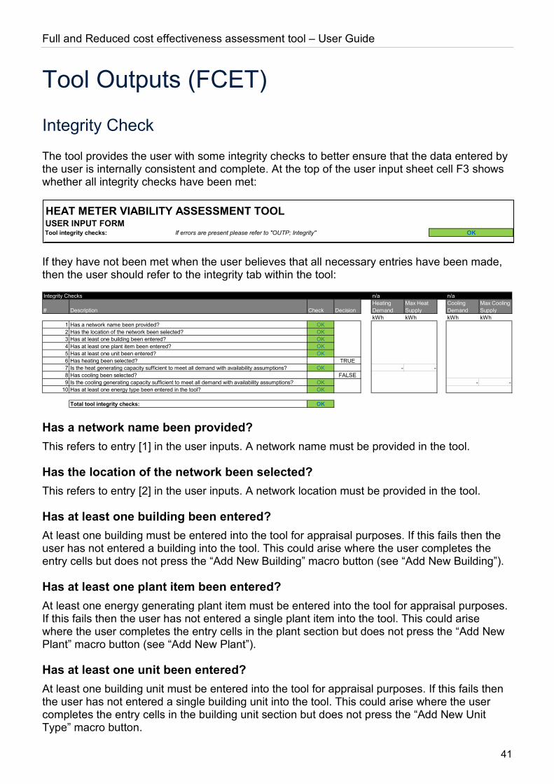
Full and Reduced cost effectiveness assessment tool – User Guide
41
Tool Outputs (FCET)
Integrity Check
The tool provides the user with some integrity checks to better ensure that the data entered by the user is internally consistent and complete. At the top of the user input sheet cell F3 shows whether all integrity checks have been met:
If they have not been met when the user believes that all necessary entries have been made, then the user should refer to the integrity tab within the tool:
Has a network name been provided? This refers to entry [1] in the user inputs. A network name must be provided in the tool.
Has the location of the network been selected? This refers to entry [2] in the user inputs. A network location must be provided in the tool.
Has at least one building been entered? At least one building must be entered into the tool for appraisal purposes. If this fails then the user has not entered a building into the tool. This could arise where the user completes the entry cells but does not press the “Add New Building” macro button (see “Add New Building”).
Has at least one plant item been entered? At least one energy generating plant item must be entered into the tool for appraisal purposes. If this fails then the user has not entered a single plant item into the tool. This could arise where the user completes the entry cells in the plant section but does not press the “Add New Plant” macro button (see “Add New Plant”).
Has at least one unit been entered? At least one building unit must be entered into the tool for appraisal purposes. If this fails then the user has not entered a single building unit into the tool. This could arise where the user completes the entry cells in the building unit section but does not press the “Add New Unit Type” macro button.
HEAT METER VIABILITY ASSESSMENT TOOLUSER INPUT FORMTool integrity checks: If errors are present please refer to "OUTP; Integrity" OK
Integrity Checks
# Description Check DecisionHeating Demand
Max Heat Supply
Cooling Demand
Max Cooling Supply
kWh kWh kWh kWh1 Has a network name been provided? OK2 Has the location of the network been selected? OK3 Has at least one building been entered? OK4 Has at least one plant item been entered? OK5 Has at least one unit been entered? OK6 Has heating been selected? TRUE7 Is the heat generating capacity sufficient to meet all demand with availability assumptions? OK - -8 Has cooling been selected? FALSE9 Is the cooling generating capacity sufficient to meet all demand with availability assumptions? OK - -
10 Has at least one energy type been entered in the tool? OK
Total tool integrity checks: OK
n/a n/a
Full and Reduced cost effectiveness assessment tool – User Guide
42
Has heating been selected? If the user has selected that heating is supplied to at least one building unit type ([C10]) then:
Is the heat generating capacity sufficient to meet all demand with availability assumptions? This checks whether total heating demand for a given building is met by total heat supply. If it does not then cell G3 (on image above: “n/a” above heating demand) will provide the building name entered by the user of the building where the heat supplied by the plant entered is not sufficient to meet the demand estimated by the tool. In the columns below the building name the tool provides the total heating demand estimated across all the units within the building (integrity check #7, G12) and the maximum annual heating supply that the plant entered by the user could supply (integrity check #7, H12). Fundamentally this is the plant’s thermal capacity allocated to the building ([B7]) multiplied by the plant’s availability ([B12]) multiplied by the number of hours in the year (8760). If this is less than the demand then it either suggests that there has been an error in the spatial values of the building units entered or else that the plant values have been incorrectly entered (e.g. MWth instead of the required kWth plant capacity).
Has cooling been selected? If the user has selected that cooling is supplied to at least one building unit type ([C18]) then:
Is the cooling generating capacity sufficient to meet all demand with availability assumptions? This checks whether total cooling demand for a given building is met by total heat supply. If it does not then cell J3 (on image above: “n/a” above cooling demand) will provide the building name entered by the user of the building where the cooling supplied by the plant entered is not sufficient to meet the demand estimated by the tool. In the columns below the building name the tool provides the total cooling demand estimated across all the units within the building (integrity check #9, J14) and the maximum annual cooling supply that the plant entered by the user could supply (integrity check #9, K14). Fundamentally this is the plant’s cooling capacity allocated to the building ([B8]) multiplied by the plant’s availability ([B12]) multiplied by the number of hours in the year (8760). If this is less than demand then it either suggests that there has been an error in the spatial values of the building units entered or else that the plant values have been incorrectly entered (e.g. MWcoolth instead of the required kWcoolth plant capacity).
Has at least one energy type been entered in the tool? The tool must have at least either heating or cooling assessed in at least one building unit.
Appraisal
Having entered all of the network’s buildings, heat/cooling generating plant and building unit types within buildings and confirmed that all integrity checks have been met, the Appraisal tab provides the user with the assessment of whether a) heat meters should be installed; and failing that whether b) heat cost allocators should be installed.
The appraisal is on a building by building basis, not a whole network basis. For each building entered into the tool a corresponding line entry is provided:

Full and Reduced cost effectiveness assessment tool – User Guide
43
The tool first assesses whether a net present benefit arises on installing heat meters over a 10 year assessment period. The above example would suggest that Heat Cost Allocators would, under the regulations, be required to be installed in Building 1.
Accompanying each building some key outputs from the calculations are provided to allow the user to assess whether the values calculated are within the user’s expectations:
In the event that the heat/cooling demand and fuel consumption is at odds with expectations this may be a cause to return to the assumptions entered for the building.
Newtork 1
£ NPV / (£NPC) Meters required? £ NPV / (£NPC) HCA required?
Building 1 (22,867) FALSE 3,128 TRUE
Meter Assessment Heat Cost Allocator
Newtork 1 Total Heat demand
Total Cooling demand
Total Fuel consumed Heat Meters
Data Monitoring HCAs
Water Meters
£ NPV / (£NPC) Meters required? £ NPV / (£NPC) HCA required? kWh/Y kWh/Y kWh/Y # # # #
Building 1 (22,867) FALSE 3,128 TRUE 118,800 - 40,340 - - 100 1
Meter Assessment Heat Cost Allocator

Full and Reduced cost effectiveness assessment tool – User Guide
44
Core Calculations (FCET)
Underlying principles
Establishing demand
The tool is intended to provide a sufficient level of detail such that reasonable estimates for heat demand, relating to the provision of space heating, and the associated cost of metering can be made without placing too great a burden on the user of the tool.
The user is able to add buildings and unit types within each building such that an accurate representation of the buildings and the units within them can be captured. From this information heat demand estimates are established using the principles of:
• Fabric losses through external walls, roofs, glazing and floors in contact with the ground; and
• Ventilation / air infiltration air change rate per hour
Heat / cooling demand is then established based on the heat/cooling degree days for the building archetype in the UK region where the heat network is located. Where users do not specify their own estimates for fabric efficiencies and air change rates the tool uses averages of published CIBSE7 values by fabric type and unit archetype.
Other factors that will influence heating demand, such as solar irradiance through windows, thermal bridges and domestic hot water supply are not included. This is because the tool is intended to find a balance between simplicity whilst still being able to approximate a network tailored estimate for heat/cooling demand.
Cost assumptions
The actual cost of installing heat meters or cost allocators will vary depending on specific building characteristics. For this reason the Regulations provide technical exemptions to installing heat meters or heat cost allocators where it is not necessary to undertake a viability assessment.
For all other buildings supplied heat by either a communal heat network or a district heat network the costs for installing, maintaining and monitoring heat meters and heat cost allocators are assumed as follows:
Heat Meter Cost Items Units Domestic Non-Domestic
Meter cost and installation £/meter £389 £1,526
Annual meter operational costs (includes meter reading, data processing, billing)
£/meter/year £92 £92
7 Chartered Institution of Building Services Engineers: CIBSE Guide A
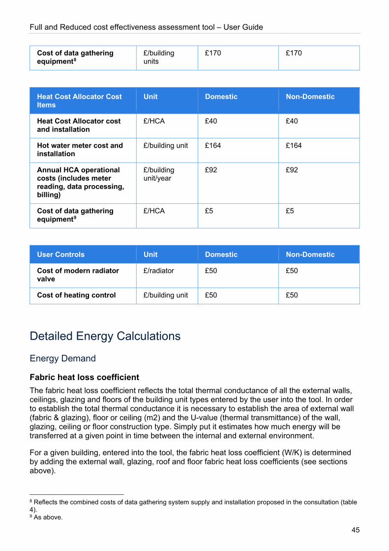
Full and Reduced cost effectiveness assessment tool – User Guide
45
Cost of data gathering equipment8
£/building units
£170 £170
Heat Cost Allocator Cost Items
Unit Domestic Non-Domestic
Heat Cost Allocator cost and installation
£/HCA £40 £40
Hot water meter cost and installation
£/building unit £164 £164
Annual HCA operational costs (includes meter reading, data processing, billing)
£/building unit/year
£92 £92
Cost of data gathering equipment9
£/HCA £5 £5
User Controls Unit Domestic Non-Domestic
Cost of modern radiator valve
£/radiator £50 £50
Cost of heating control £/building unit £50 £50
Detailed Energy Calculations
Energy Demand
Fabric heat loss coefficient The fabric heat loss coefficient reflects the total thermal conductance of all the external walls, ceilings, glazing and floors of the building unit types entered by the user into the tool. In order to establish the total thermal conductance it is necessary to establish the area of external wall (fabric & glazing), floor or ceiling (m2) and the U-value (thermal transmittance) of the wall, glazing, ceiling or floor construction type. Simply put it estimates how much energy will be transferred at a given point in time between the internal and external environment.
For a given building, entered into the tool, the fabric heat loss coefficient (W/K) is determined by adding the external wall, glazing, roof and floor fabric heat loss coefficients (see sections above).
8 Reflects the combined costs of data gathering system supply and installation proposed in the consultation (table 4). 9 As above.

Full and Reduced cost effectiveness assessment tool – User Guide
46
External wall fabric heat loss coefficient The tool establishes the total external wall area (m2) by taking the external wall perimeter length by building unit type [C9] multiplied by the average ceiling height [C8] multiplied by the number of units of that type within the building [C3] multiplied by the number of storeys in a given unit [C4]. The glazing area is established by multiplying the total surface area by either the user specified % [C11] or the tool’s stored value for the unit archetype. The difference between the total surface area and the glazing is the fabric surface area.
If the user has provided his/her own fabric efficiency assumption (W/m2 K) [A5] then this is used in the calculation. If no value has been provided or if the value provided is 0 then the fabric efficiency is sourced from CIBSE (2015), Guide A average fabric efficiency for the external wall construction type selected by the user [A3, A4]. This logic also applies to the glazing U-Value [C14, C15].
The external wall fabric heat loss coefficient (W/K) is calculated by multiplying the external wall fabric area by the fabric efficiency value plus the glazing area multiplied by the glazing U-Value.
Roof fabric heat loss coefficient The roof area (m2) is determined by the average floor space for the building unit type [C7] multiplied by the number of units of that building type that have an external roof [C5] – i.e. excluding building units that have ceilings in direct contact with the floor of the building unit above where the tool assumes the same temperature and hence no thermal transfer.
The determination of the roof fabric efficiency is the same as with the external wall with the exception that in the absence of a value provided by the user [A13] the tool looks up the CIBSE (2015), Guide A average fabric efficiency for the roof construction type selected by the user [A11, A12].
The roof fabric heat loss coefficient (W/K) is calculated by multiplying the roof area by the fabric efficiency value.
Floor fabric heat loss coefficient The floor area (m2) is determined by the average floor space for the building unit type [C7] multiplied by the number of units of that building type that are in contact with the ground [C6] – i.e. excluding building units that have floors in direct contact with the ceiling of the building unit below where the tool assumes the same temperature and hence no thermal transfer.
The determination of the floor fabric efficiency, before ground contact adjustments, is the same as with the external wall with the exception that in the absence of a value provided by the user [A9] the tool looks up the CIBSE (2015), Guide A average fabric efficiency for the floor construction type selected by the user [A8] (for values see appendix).
If the floor type is in direct contact with the ground, as opposed to being suspended and in contact with the air, then the calculation for thermal conductivity is not linear through the floor fabric. CIBSE (2015), Guide A sections 3.20 to 3.23 (2019) set out the methodology for estimating the ground contact adjusted W/m2 K conductivity of the floor. These calculations are applied to establish:
• The characteristic dimension of the floor (B’); and
• The equivalent thickness of the floor (def);

Full and Reduced cost effectiveness assessment tool – User Guide
47
The floor fabric heat loss coefficient (W/K) is calculated by multiplying the floor area by the ground adjusted (if applicable) U-Value of the floor.
Ventilation / infiltration heat loss coefficient The ventilation / infiltration heat loss coefficient reflects the energy required to heat the air that circulates within a given building unit. Essentially the more frequently the external air replaces the internal air, the greater amount of energy is required to elevate the external air temperature to the desired internal air temperature. Air change occurs primarily due to two reasons:
• Mechanical ventilation takes internal air and exchanges it with external air. This is important for avoiding internal condensation among other things;
• Air tightness – cracks under doors, windows etc. as well as the pores within building fabric mean that air will circulate in the absence of mechanical ventilation.
In order to calculate the ventilation / infiltration heat loss coefficient it necessary to know the internal volume of the building unit (m3), the number of times that the air changes per hour (change / hour) and the energy required to raise one cubic meter of air by one degree kelvin which is an empirically established value of 0.33 Wh/m3K.
The internal volume of a given building unit type entered into the tool is established by multiplying the total number of building units of that type in the building [C3] by the average floor space per unit [C7] by the average building unit ceiling height [C8].
The ventilation / infiltration heat loss coefficient (W/K) is calculated by multiplying the internal volume by 0.33 (the volume based heat capacity of air) by the number of air changes per hour.
Heat / Cooling Demand at the building unit level The user will have selected the geographical location in section 1 of the input sheet [1] as well as the unit archetype [C2]. For each archetype and geographical location heating and cooling degree day values are stored in the tool.
The degree day values have been established as follows:
• Met Office hourly average temperatures for each UK region were obtained for the period 01/01/2014 – 31/12/2018;
• For each building archetype an assumption was made for the hourly heating and cooling regimes over weekdays and weekends was made, in line with CIBSE guidance10;
• A heating event is assessed to occur in the event that the hourly temperature in a given region was below the base temperature for that building (typically assumed to be 15.5 Degrees Celsius) and the hour in which the event occurred was set as part of the heating regime. The heating degree days for that hour would be calculated to be the difference between the base temperature and the outdoor temperature divided by 24.
• A cooling event is assessed to occur in the event that the hourly temperature in a given region was above the base temperature and the hour in which the event occurred was set as part of the cooling regime. The cooling degree days for that hour would be
10 CIBSE TM46: Energy Benchmarks
Full and Reduced cost effectiveness assessment tool – User Guide
48
calculated to be the difference between the outdoor temperature and the base temperature for cooling.
Degree days are an important part of the heat / cooling demand calculation as they represent the temperature differential (Delta-T) that needs to be overcome in order to keep the dwelling at the target internal temperature.
Heat/cooling demand (kWh) is calculated by multiplying the sum of the fabric and ventilation / air infiltration heat loss coefficients by the heating/cooling degrees days11. If the user has selected that heat [C18] or cooling [C19] is not supplied to that building unit (e.g. there is no air conditioning) then no demand for that building unit will be calculated.
Heat / Cooling Demand at the building level The tool aggregates all the calculated heat and cooling demand by building such that a total heat and cooling demand by building is established and presented in annual kWh values.
Energy Supply Calculations
Overview
A core part of the cost/benefit analysis is the cost of fuel that is assumed to be saved by heat/cooling customers. In order to establish this it is necessary to first understand the heating/cooling demand of each building supplied by the heat network. Having established this (see section above) it is then necessary to estimate the fuel required to supply that heat/cooling to customers.
In order to do this the tool gathers information on the heat/cooling plant that is available to the network. A key challenge is establishing fuel consumption is that more complex schemes will have a variety of plant capable of delivering heat or cooling. For example, a district heat network may have a water-source heat pump that operates throughout the year. In peak winter periods further plant, such as gas boilers, may be used to top up the heat requirement. The heat pump may be an electric heat pump meaning that for much of the heat supplied a reduction in heat would mean that electricity consumption is reduced. However, for some of the supply when the gas boilers are being operated, a heat reduction would result in lower gas costs also.
The tool attempts to address the hierarchy of heat / cooling dispatch as follows:
• The user can enter the dispatch ranking of the heat / cooling plant entered into the tool for a given item of plant within a given building; or
• If the user is unsure then the tool will establish a dispatch hierarchy on the basis that the plant is operated with lowest carbon impact in mind;
Energy dispatch hierarchy not provided by user
If the user does not provide a relative ranking for heat / cooling dispatch then the tool will rank any unranked plant on the basis of carbon equivalent emissions. It does this as follows:
11 As the heat loss coefficient is expressed in W/K it is necessary to divide by 1000 in order to express the demand in kWh values.
Full and Reduced cost effectiveness assessment tool – User Guide
49
• Some plant will also produce electricity. As such when the plant is used to provide heat and potentially cooling there is a potential benefit of displacing other forms of electricity generation. As the carbon content of electricity on the national grid reduces this benefit diminishes. The electricity generating efficiency of the plant is established by taking the total plant efficiency entered by the user [B11] less the heat [B9] and cooling [B10] generating efficiencies entered by the user. The plant’s capacity (kWe) to displace electricity is established from this and the carbon offsetting potential of the plant is calculated by multiplying the electricity generating capacity with the long run marginal average commercial / public sector kgCO2e of electricity consumption;
• The fuel type for the plant is selected by the user [B5]. The carbon content (kgCO2e/kWh) of the fuel type selected is stored within the tool and is sourced from published guidance12. This is adjusted to reflect the thermal or cooling conversion efficiency of the plant;
• Any emissions relating to displaced electricity are subtracted from the fuel consumption emissions;
• The emissions are then ranked from lowest emissions to highest. Where there are duplicates then the ranking follows the user’s input sequence with plant entered first being ranked higher than those entered last;
• Having calculated separate dispatch hierarchies for heat and cooling supply the user’s dispatch hierarchies for heat [B13] and cooling [B14] are overlaid such that the tool’s determined hierarchies come after the dispatch hierarchy entered by the user.
For example, if the user entered a CHP engine as primary dispatch and separately entered a water-source heat pump and 2 gas boilers with no dispatch assumptions; the tool would rank the water-source heat pump (WSHP) as first and the gas boilers as second for heat dispatch. It would then set the CHP as the first heat dispatch, the WSHP as second and the gas boilers as third.
Heat / cooling supply
Having determined the plant dispatch hierarchy for both heating and cooling for a given building, the tool then determines the heat supplied by different plant types entered up to the point that the heat / cooling demand calculated has been met. Where plant is not located in the building, distribution losses are calculated based on the user’s input [B4], and the heat supply value is amended to reflect both the distribution losses plus the demand.
The plant’s availability [B12] is an important part of the calculation as while a plant item may have the capacity to deliver heat or cooling it may not be available to do so. For example, some plant may only be operated in winter/summer periods. The calculation of heat supply by plant type is therefore the plant’s capacity multiplied by its availability (hours in the year) limited by the amount of heat / cooling demand not already allocated a supply by the tool.
12 Green Book supplementary guidance: valuation of energy use and greenhouse gas emissions for appraisal
https://www.gov.uk/government/publications/valuation-of-energy-use-and-greenhouse-gas-emissions-for-appraisal
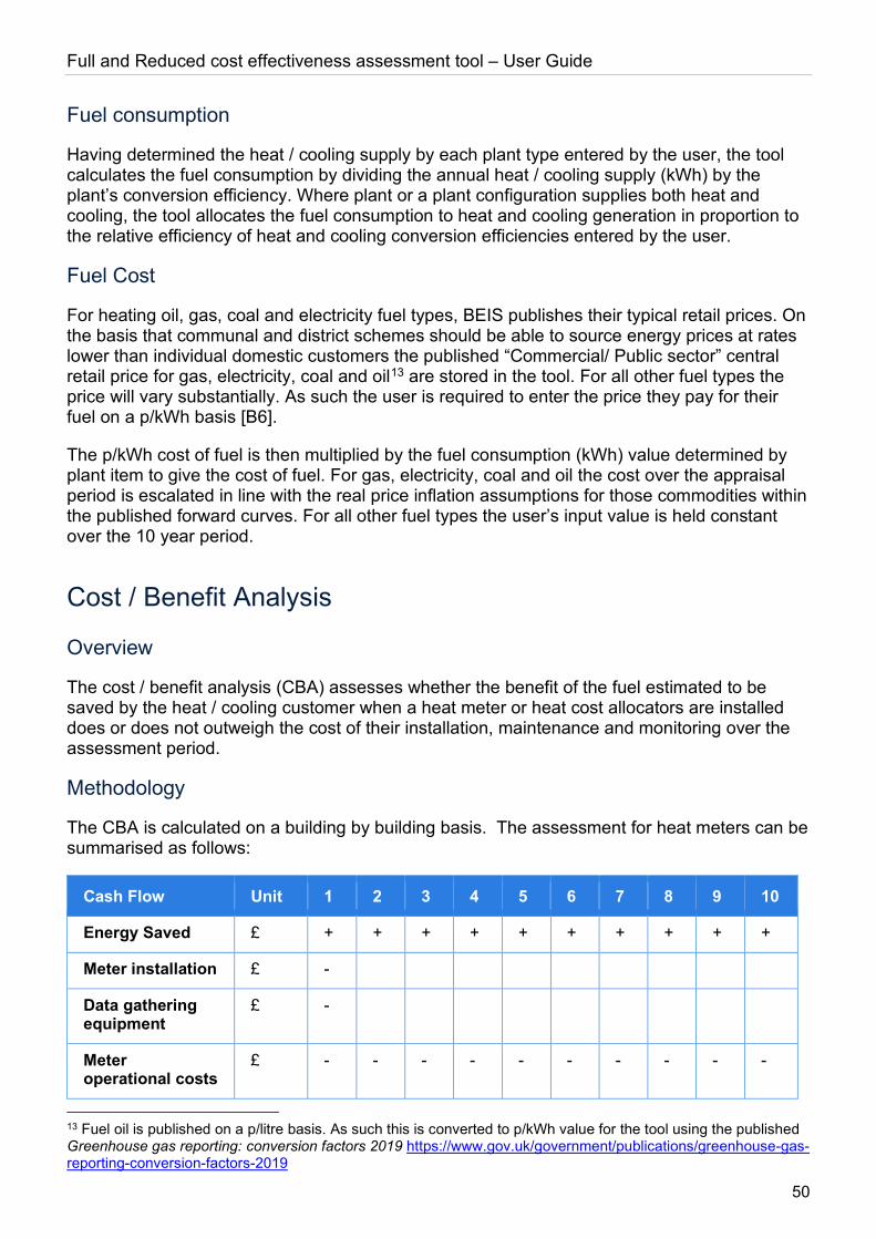
Full and Reduced cost effectiveness assessment tool – User Guide
50
Fuel consumption
Having determined the heat / cooling supply by each plant type entered by the user, the tool calculates the fuel consumption by dividing the annual heat / cooling supply (kWh) by the plant’s conversion efficiency. Where plant or a plant configuration supplies both heat and cooling, the tool allocates the fuel consumption to heat and cooling generation in proportion to the relative efficiency of heat and cooling conversion efficiencies entered by the user.
Fuel Cost
For heating oil, gas, coal and electricity fuel types, BEIS publishes their typical retail prices. On the basis that communal and district schemes should be able to source energy prices at rates lower than individual domestic customers the published “Commercial/ Public sector” central retail price for gas, electricity, coal and oil13 are stored in the tool. For all other fuel types the price will vary substantially. As such the user is required to enter the price they pay for their fuel on a p/kWh basis [B6].
The p/kWh cost of fuel is then multiplied by the fuel consumption (kWh) value determined by plant item to give the cost of fuel. For gas, electricity, coal and oil the cost over the appraisal period is escalated in line with the real price inflation assumptions for those commodities within the published forward curves. For all other fuel types the user’s input value is held constant over the 10 year period.
Cost / Benefit Analysis
Overview
The cost / benefit analysis (CBA) assesses whether the benefit of the fuel estimated to be saved by the heat / cooling customer when a heat meter or heat cost allocators are installed does or does not outweigh the cost of their installation, maintenance and monitoring over the assessment period.
Methodology
The CBA is calculated on a building by building basis. The assessment for heat meters can be summarised as follows:
Cash Flow Unit 1 2 3 4 5 6 7 8 9 10
Energy Saved £ + + + + + + + + + +
Meter installation £ -
Data gathering equipment
£ -
Meter operational costs
£ - - - - - - - - - -
13 Fuel oil is published on a p/litre basis. As such this is converted to p/kWh value for the tool using the published Greenhouse gas reporting: conversion factors 2019 https://www.gov.uk/government/publications/greenhouse-gas-reporting-conversion-factors-2019
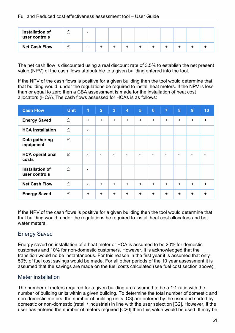
Full and Reduced cost effectiveness assessment tool – User Guide
51
Installation of user controls
£ -
Net Cash Flow £ - + + + + + + + + +
The net cash flow is discounted using a real discount rate of 3.5% to establish the net present value (NPV) of the cash flows attributable to a given building entered into the tool.
If the NPV of the cash flows is positive for a given building then the tool would determine that that building would, under the regulations be required to install heat meters. If the NPV is less than or equal to zero then a CBA assessment is made for the installation of heat cost allocators (HCA). The cash flows assessed for HCAs is as follows:
Cash Flow Unit 1 2 3 4 5 6 7 8 9 10
Energy Saved £ + + + + + + + + + +
HCA installation £ -
Data gathering equipment
£ -
HCA operational costs
£ - - - - - - - - - -
Installation of user controls
£ -
Net Cash Flow £ - + + + + + + + + +
Energy Saved £ + + + + + + + + + +
If the NPV of the cash flows is positive for a given building then the tool would determine that that building would, under the regulations be required to install heat cost allocators and hot water meters.
Energy Saved
Energy saved on installation of a heat meter or HCA is assumed to be 20% for domestic customers and 10% for non-domestic customers. However, it is acknowledged that the transition would no be instantaneous. For this reason in the first year it is assumed that only 50% of fuel cost savings would be made. For all other periods of the 10 year assessment it is assumed that the savings are made on the fuel costs calculated (see fuel cost section above).
Meter installation
The number of meters required for a given building are assumed to be a 1:1 ratio with the number of building units within a given building. To determine the total number of domestic and non-domestic meters, the number of building units [C3] are entered by the user and sorted by domestic or non-domestic (retail / industrial) in line with the user selection [C2]. However, if the user has entered the number of meters required [C20] then this value would be used. It may be
Full and Reduced cost effectiveness assessment tool – User Guide
52
necessary that more than one meter is required per building unit – this is the means for allowing the user to reflect some of the additional costs such a configuration would entail.
The cost of the meter for domestic meters (see cost section above) is multiplied by the number of domestic meters required for the building. The same approach is taken for non-domestic meters.
Data gathering equipment
This is the annual cost per building unit of gathering data for invoicing purposes from either heat meters or HCAs. It includes the supply and installation of the equipment. The total cost is the number of units per building multiplied by the cost of data gathering equipment per unit.
Operational costs for meters and HCAs
The annual operational cost is per meter or per building unit, in the case of HCAs, and includes meter reading, data processing and billing information. The total cost is the number of units per building multiplied by the annual cost, unless a different number of meters has been provided for the building.
Installation of user controls
For any building unit type that the user has selected that the occupant is unable to control their heat demand (e.g. in the absence of controls or thermostatic valves on radiators) [C21], the number of controls required to be installed for that building unit is:
• one per unit for heat meters or
• the number of radiators in each unit of that type [C22] where HCA are installed.
The cost of controls is the number of controls multiplied by the cost of controls (£/control) – see cost assumptions section.
HCA Installation
The number of HCAs required per dwelling is assessed to be the number of radiators [C22] within the dwelling.
The cost of HCAs is the cost per HCA multiplied by the number of HCAs required.
Water meter installation
In order to allow for HCAs to function it is necessary to monitor to also monitor the total water flow into the building unit relating to the heating system. The number of water meters required is equivalent to the number of building units within the building.
The cost of water meter installation is the number water meters required multiplied by the cost of each meter (domestic and non-domestic).
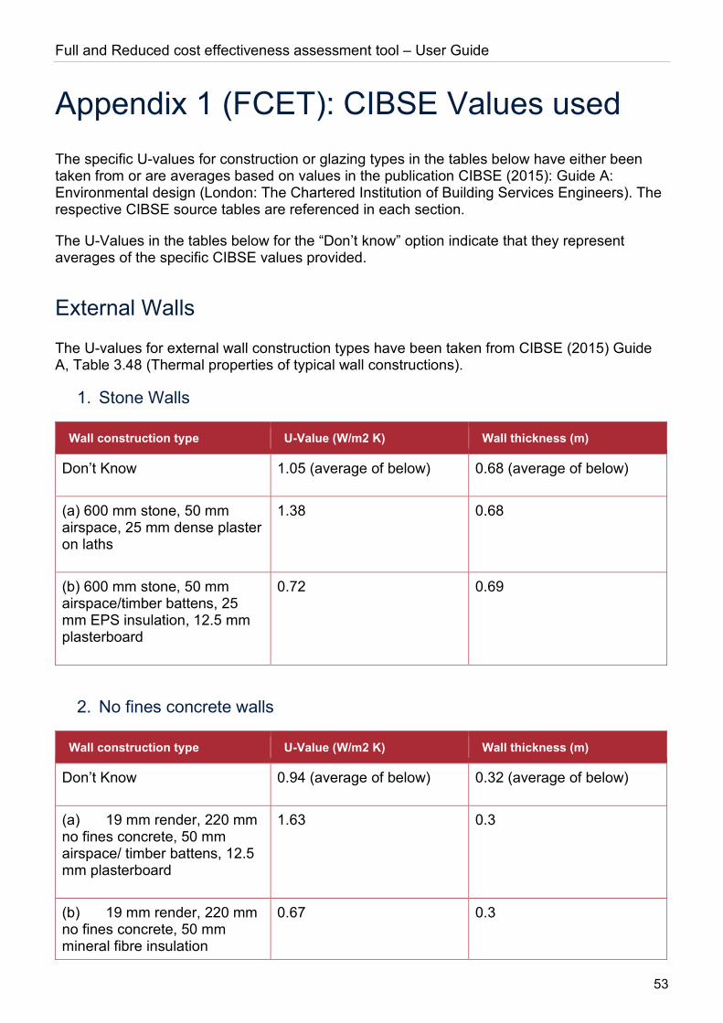
Full and Reduced cost effectiveness assessment tool – User Guide
53
Appendix 1 (FCET): CIBSE Values used The specific U-values for construction or glazing types in the tables below have either been taken from or are averages based on values in the publication CIBSE (2015): Guide A: Environmental design (London: The Chartered Institution of Building Services Engineers). The respective CIBSE source tables are referenced in each section.
The U-Values in the tables below for the “Don’t know” option indicate that they represent averages of the specific CIBSE values provided.
External Walls
The U-values for external wall construction types have been taken from CIBSE (2015) Guide A, Table 3.48 (Thermal properties of typical wall constructions).
1. Stone Walls
Wall construction type U-Value (W/m2 K) Wall thickness (m)
Don’t Know 1.05 (average of below) 0.68 (average of below)
(a) 600 mm stone, 50 mm airspace, 25 mm dense plaster on laths
1.38 0.68
(b) 600 mm stone, 50 mm airspace/timber battens, 25 mm EPS insulation, 12.5 mm plasterboard
0.72 0.69
2. No fines concrete walls
Wall construction type U-Value (W/m2 K) Wall thickness (m)
Don’t Know 0.94 (average of below) 0.32 (average of below)
(a) 19 mm render, 220 mm no fines concrete, 50 mm airspace/ timber battens, 12.5 mm plasterboard
1.63 0.3
(b) 19 mm render, 220 mm no fines concrete, 50 mm mineral fibre insulation
0.67 0.3
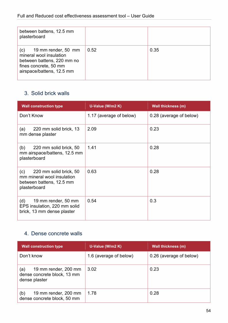
Full and Reduced cost effectiveness assessment tool – User Guide
54
between battens, 12.5 mm plasterboard
(c) 19 mm render, 50 mm mineral wool insulation between battens, 220 mm no fines concrete, 50 mm airspace/battens, 12.5 mm
0.52 0.35
3. Solid brick walls
Wall construction type U-Value (W/m2 K) Wall thickness (m)
Don’t Know 1.17 (average of below) 0.28 (average of below)
(a) 220 mm solid brick, 13 mm dense plaster
2.09 0.23
(b) 220 mm solid brick, 50 mm airspace/battens, 12.5 mm plasterboard
1.41 0.28
(c) 220 mm solid brick, 50 mm mineral wool insulation between battens, 12.5 mm plasterboard
0.63 0.28
(d) 19 mm render, 50 mm EPS insulation, 220 mm solid brick, 13 mm dense plaster
0.54 0.3
4. Dense concrete walls
Wall construction type U-Value (W/m2 K) Wall thickness (m)
Don’t know 1.6 (average of below) 0.26 (average of below)
(a) 19 mm render, 200 mm dense concrete block, 13 mm dense plaster
3.02 0.23
(b) 19 mm render, 200 mm dense concrete block, 50 mm
1.78 0.28

Full and Reduced cost effectiveness assessment tool – User Guide
55
airspace/battens, 12.5 mm plasterboard
(c) 19 mm render, 200 mm dense concrete block, 25 mm polyurethane insulation between battens, 12.5 mm plasterboard
0.9 0.26
(d) 19 mm render, 50 mm mineral wool between battens, 200 mm dense concrete block, 13 mm dense plaster
0.7 0.28
5. Precast concrete panel walls
Wall construction type U-Value (W/m2 K) Wall thickness (m)
Don’t know 0.78 (average of below) 0.25 (average of below)
(a) 80 mm dense concrete, 25 mm EPS insulation, 100 mm dense concrete, 13 mm dense plaster
1.07 0.22
(b) 80 mm dense concrete, 25 mm EPS insulation, 100 mm dense concrete, 50 mm airspace/battens, 12.5 mm plasterboard
0.85 0.27
(c) 80 mm dense concrete, 50 mm EPS insulation, 100 mm dense concrete, 12.5 mm plasterboard
0.56 0.24
(d) 19 mm render, 80 mm dense concrete, 50 mm EPS insulation, 100 mm dense concrete, 13 mm dense plaster
0.63 0.26
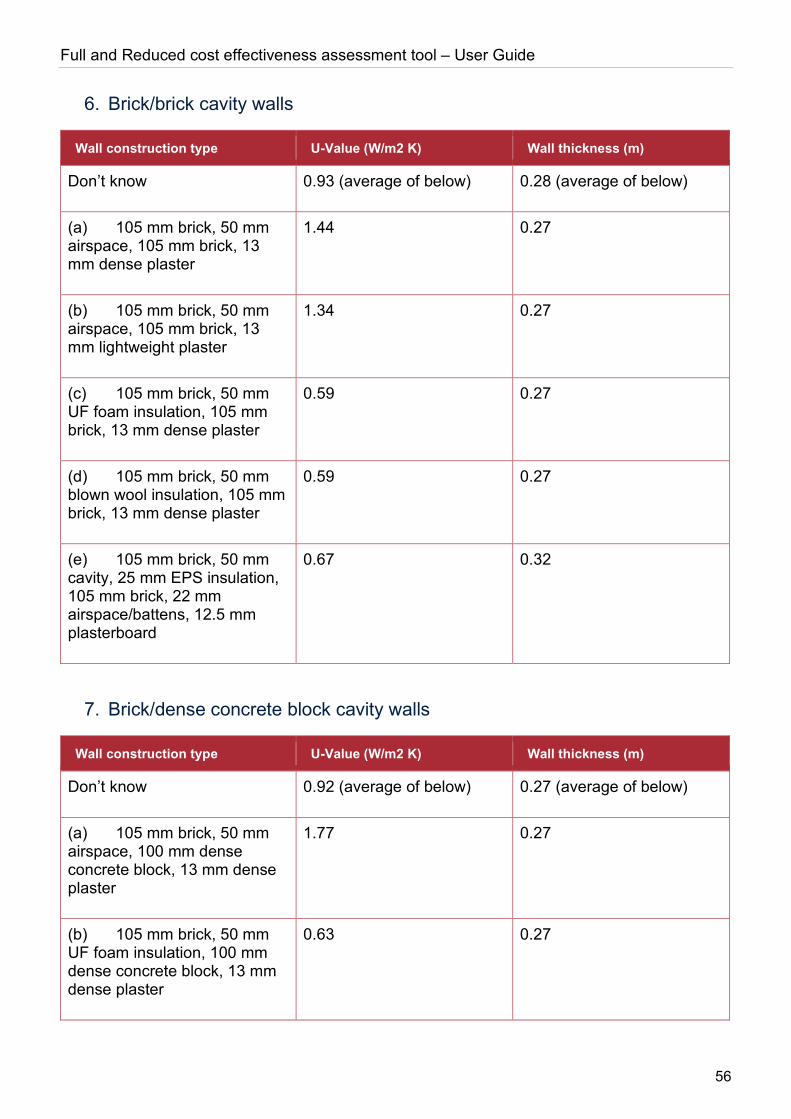
Full and Reduced cost effectiveness assessment tool – User Guide
56
6. Brick/brick cavity walls
Wall construction type U-Value (W/m2 K) Wall thickness (m)
Don’t know 0.93 (average of below) 0.28 (average of below)
(a) 105 mm brick, 50 mm airspace, 105 mm brick, 13 mm dense plaster
1.44 0.27
(b) 105 mm brick, 50 mm airspace, 105 mm brick, 13 mm lightweight plaster
1.34 0.27
(c) 105 mm brick, 50 mm UF foam insulation, 105 mm brick, 13 mm dense plaster
0.59 0.27
(d) 105 mm brick, 50 mm blown wool insulation, 105 mm brick, 13 mm dense plaster
0.59 0.27
(e) 105 mm brick, 50 mm cavity, 25 mm EPS insulation, 105 mm brick, 22 mm airspace/battens, 12.5 mm plasterboard
0.67 0.32
7. Brick/dense concrete block cavity walls
Wall construction type U-Value (W/m2 K) Wall thickness (m)
Don’t know 0.92 (average of below) 0.27 (average of below)
(a) 105 mm brick, 50 mm airspace, 100 mm dense concrete block, 13 mm dense plaster
1.77 0.27
(b) 105 mm brick, 50 mm UF foam insulation, 100 mm dense concrete block, 13 mm dense plaster
0.63 0.27

Full and Reduced cost effectiveness assessment tool – User Guide
57
(c) 105 mm brick, 50 mm blown fibre insulation, 100 mm dense concrete block, 13 mm dense plaster
0.63 0.27
(d) 105 mm brick, 50 mm EPS insulation, 100 mm dense concrete block, 13 mm dense plaster
0.64 0.27
8. Brick/lightweight aggregate concrete block cavity walls
Wall construction type U-Value (W/m2 K) Wall thickness (m)
Don’t know 0.6 (average of below) 0.28 (average of below)
(a) 105 mm brick, 50 mm airspace, 100 mm lightweight aggregate concrete block, 13 mm dense plaster
1.06 0.27
(b) 105 mm brick, 50 mm UF foam insulation, 100 mm lightweight aggregate concrete block, 13 mm dense plaster
0.52 0.27
(c) 105 mm brick, 50 mm blown fibre insulation, 100 mm lightweight aggregate concrete block, 13 mm dense plaster
0.52 0.27
(d) 105 mm brick, 100 mm blown fibre insulation, 100 mm lightweight aggregate concrete block, 13 mm dense plaster
0.33 0.32
(e) 105 mm brick, 50 mm EPS insulation, 100 mm lightweight aggregate concrete block, 13 mm dense plaster
0.52 0.27
(f) 105 mm brick, 25 mm airspace, 25 mm EPS insulation, 100 mm lightweight
0.66 0.27
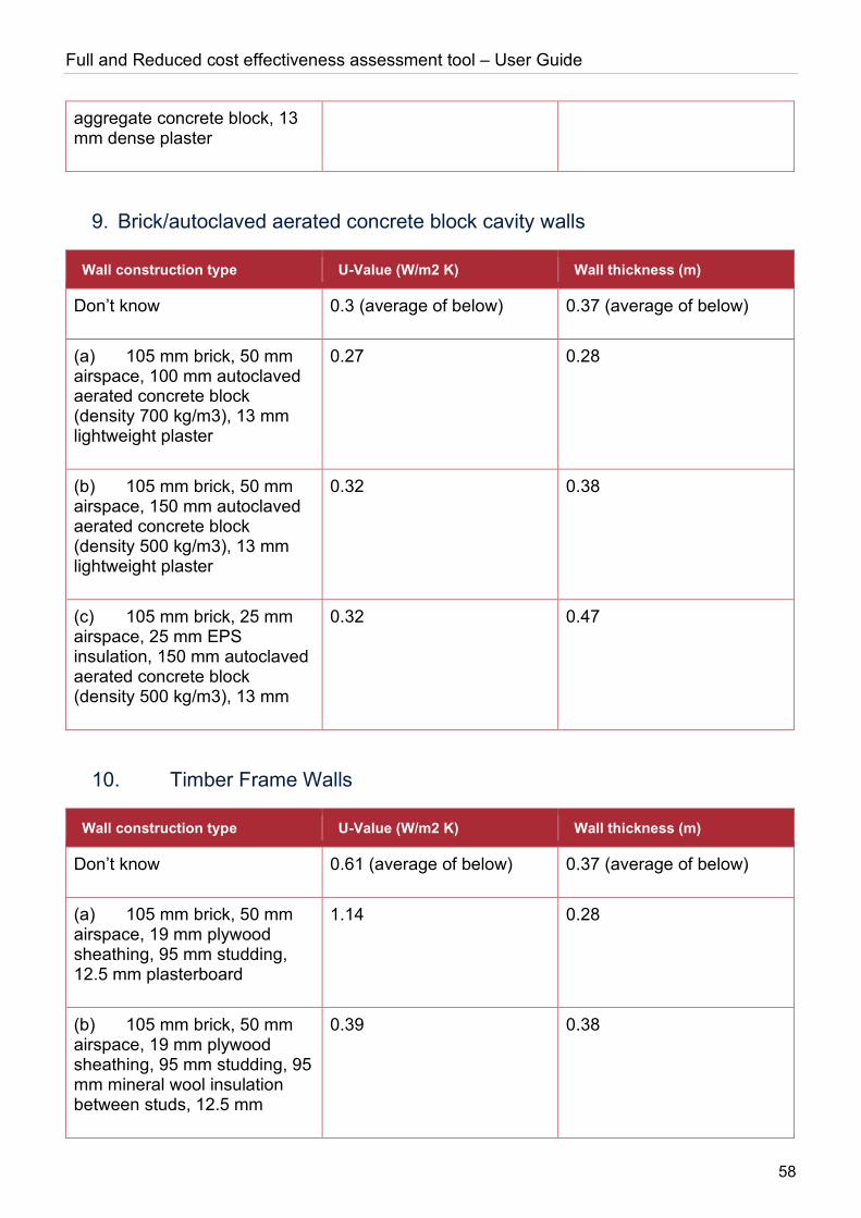
Full and Reduced cost effectiveness assessment tool – User Guide
58
aggregate concrete block, 13 mm dense plaster
9. Brick/autoclaved aerated concrete block cavity walls
Wall construction type U-Value (W/m2 K) Wall thickness (m)
Don’t know 0.3 (average of below) 0.37 (average of below)
(a) 105 mm brick, 50 mm airspace, 100 mm autoclaved aerated concrete block (density 700 kg/m3), 13 mm lightweight plaster
0.27 0.28
(b) 105 mm brick, 50 mm airspace, 150 mm autoclaved aerated concrete block (density 500 kg/m3), 13 mm lightweight plaster
0.32 0.38
(c) 105 mm brick, 25 mm airspace, 25 mm EPS insulation, 150 mm autoclaved aerated concrete block (density 500 kg/m3), 13 mm
0.32 0.47
10. Timber Frame Walls
Wall construction type U-Value (W/m2 K) Wall thickness (m)
Don’t know 0.61 (average of below) 0.37 (average of below)
(a) 105 mm brick, 50 mm airspace, 19 mm plywood sheathing, 95 mm studding, 12.5 mm plasterboard
1.14 0.28
(b) 105 mm brick, 50 mm airspace, 19 mm plywood sheathing, 95 mm studding, 95 mm mineral wool insulation between studs, 12.5 mm
0.39 0.38
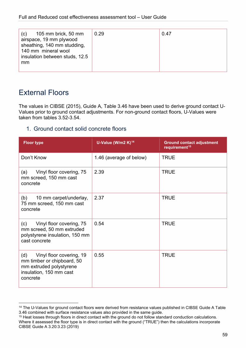
Full and Reduced cost effectiveness assessment tool – User Guide
59
(c) 105 mm brick, 50 mm airspace, 19 mm plywood sheathing, 140 mm studding, 140 mm mineral wool insulation between studs, 12.5 mm
0.29 0.47
External Floors
The values in CIBSE (2015), Guide A, Table 3.46 have been used to derive ground contact U-Values prior to ground contact adjustments. For non-ground contact floors, U-Values were taken from tables 3.52-3.54.
1. Ground contact solid concrete floors
Floor type U-Value (W/m2 K)14 Ground contact adjustment requirement15
Don’t Know 1.46 (average of below) TRUE
(a) Vinyl floor covering, 75 mm screed, 150 mm cast concrete
2.39 TRUE
(b) 10 mm carpet/underlay, 75 mm screed, 150 mm cast concrete
2.37 TRUE
(c) Vinyl floor covering, 75 mm screed, 50 mm extruded polystyrene insulation, 150 mm cast concrete
0.54 TRUE
(d) Vinyl floor covering, 19 mm timber or chipboard, 50 mm extruded polystyrene insulation, 150 mm cast concrete
0.55 TRUE
14 The U-Values for ground contact floors were derived from resistance values published in CIBSE Guide A Table 3.46 combined with surface resistance values also provided in the same guide. 15 Heat losses through floors in direct contact with the ground do not follow standard conduction calculations. Where it assessed the floor type is in direct contact with the ground (“TRUE”) then the calculations incorporate CIBSE Guide A 3.20:3.23 (2019)

Full and Reduced cost effectiveness assessment tool – User Guide
60
2. Ground contact suspended timber floors
Floor type U-Value (W/m2 K) Ground contact adjustment requirement
Don’t Know 1.75 (average of below) TRUE
(a) Vinyl floor covering, 19 mm timber or chipboard on 100 mm joists, ventilated underfloor cavity
3.15 TRUE
(b) Vinyl floor covering, 19 mm timber or chipboard on 100 mm joists, 100 mm mineral fibre between joists, ventilated underfloor cavity
0.37 TRUE
(c) 10 mm carpet/underlay, 19 mm timber or chipboard on 100 mm joists, ventilated underfloor cavity
3.1 TRUE
(d) 10 mm carpet/underlay, 19 mm timber or chipboard on 100 mm joists, 100 mm mineral fibre between joists, ventilated underfloor cavity
0.37 TRUE
3. Outside air contact floors
Floor type U-Value (W/m2 K) Ground contact adjustment requirement
Don’t Know 0.85 (average of below) FALSE
(a) Vinyl floor covering, 50 mm screed, 150 mm cast concrete
2.26 FALSE
(b) Vinyl floor covering, 50 mm screed, 150 mm cast concrete, 50 mm mineral fibre insulation between battens, 12
0.63 FALSE
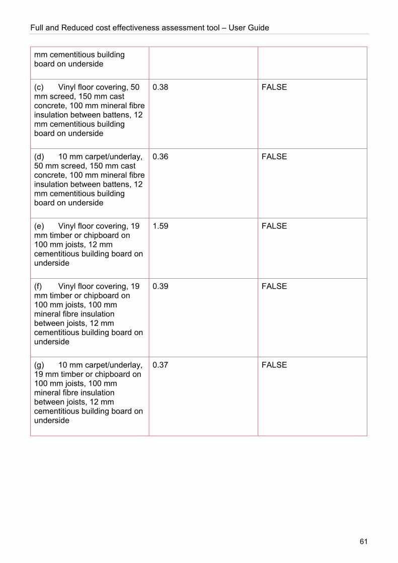
Full and Reduced cost effectiveness assessment tool – User Guide
61
mm cementitious building board on underside
(c) Vinyl floor covering, 50 mm screed, 150 mm cast concrete, 100 mm mineral fibre insulation between battens, 12 mm cementitious building board on underside
0.38 FALSE
(d) 10 mm carpet/underlay, 50 mm screed, 150 mm cast concrete, 100 mm mineral fibre insulation between battens, 12 mm cementitious building board on underside
0.36 FALSE
(e) Vinyl floor covering, 19 mm timber or chipboard on 100 mm joists, 12 mm cementitious building board on underside
1.59 FALSE
(f) Vinyl floor covering, 19 mm timber or chipboard on 100 mm joists, 100 mm mineral fibre insulation between joists, 12 mm cementitious building board on underside
0.39 FALSE
(g) 10 mm carpet/underlay, 19 mm timber or chipboard on 100 mm joists, 100 mm mineral fibre insulation between joists, 12 mm cementitious building board on underside
0.37 FALSE
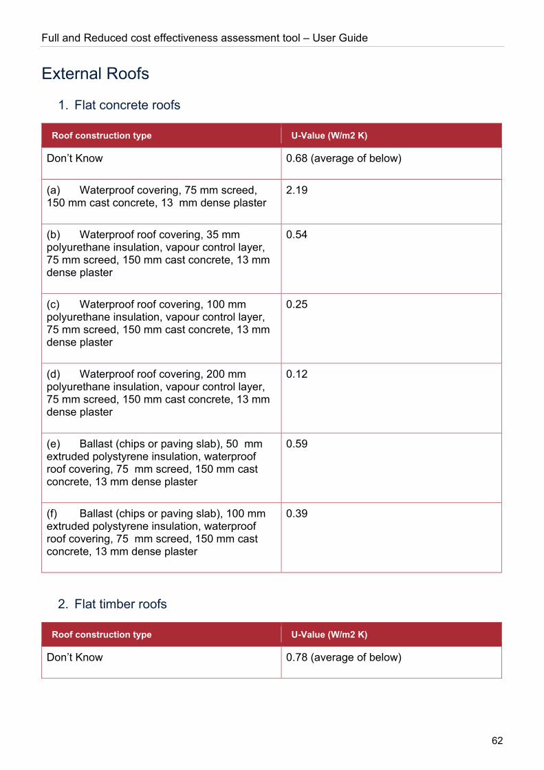
Full and Reduced cost effectiveness assessment tool – User Guide
62
External Roofs
1. Flat concrete roofs
Roof construction type U-Value (W/m2 K)
Don’t Know 0.68 (average of below)
(a) Waterproof covering, 75 mm screed, 150 mm cast concrete, 13 mm dense plaster
2.19
(b) Waterproof roof covering, 35 mm polyurethane insulation, vapour control layer, 75 mm screed, 150 mm cast concrete, 13 mm dense plaster
0.54
(c) Waterproof roof covering, 100 mm polyurethane insulation, vapour control layer, 75 mm screed, 150 mm cast concrete, 13 mm dense plaster
0.25
(d) Waterproof roof covering, 200 mm polyurethane insulation, vapour control layer, 75 mm screed, 150 mm cast concrete, 13 mm dense plaster
0.12
(e) Ballast (chips or paving slab), 50 mm extruded polystyrene insulation, waterproof roof covering, 75 mm screed, 150 mm cast concrete, 13 mm dense plaster
0.59
(f) Ballast (chips or paving slab), 100 mm extruded polystyrene insulation, waterproof roof covering, 75 mm screed, 150 mm cast concrete, 13 mm dense plaster
0.39
2. Flat timber roofs
Roof construction type U-Value (W/m2 K)
Don’t Know 0.78 (average of below)
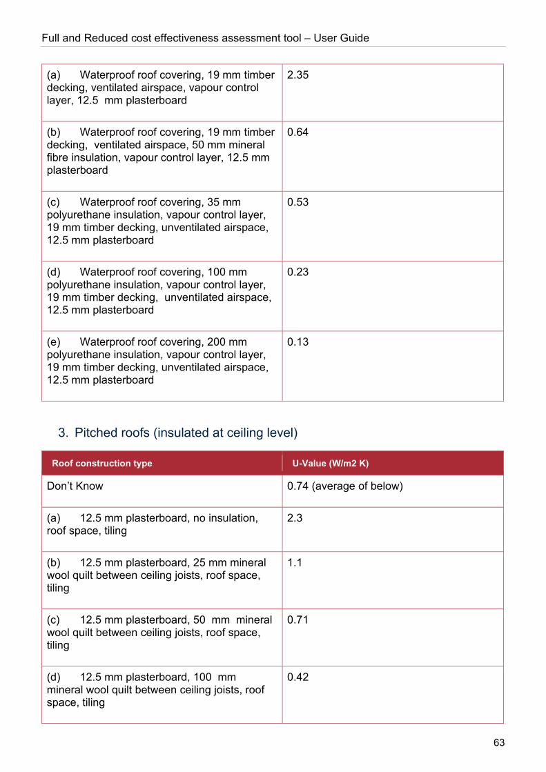
Full and Reduced cost effectiveness assessment tool – User Guide
63
(a) Waterproof roof covering, 19 mm timber decking, ventilated airspace, vapour control layer, 12.5 mm plasterboard
2.35
(b) Waterproof roof covering, 19 mm timber decking, ventilated airspace, 50 mm mineral fibre insulation, vapour control layer, 12.5 mm plasterboard
0.64
(c) Waterproof roof covering, 35 mm polyurethane insulation, vapour control layer, 19 mm timber decking, unventilated airspace, 12.5 mm plasterboard
0.53
(d) Waterproof roof covering, 100 mm polyurethane insulation, vapour control layer, 19 mm timber decking, unventilated airspace, 12.5 mm plasterboard
0.23
(e) Waterproof roof covering, 200 mm polyurethane insulation, vapour control layer, 19 mm timber decking, unventilated airspace, 12.5 mm plasterboard
0.13
3. Pitched roofs (insulated at ceiling level)
Roof construction type U-Value (W/m2 K)
Don’t Know 0.74 (average of below)
(a) 12.5 mm plasterboard, no insulation, roof space, tiling
2.3
(b) 12.5 mm plasterboard, 25 mm mineral wool quilt between ceiling joists, roof space, tiling
1.1
(c) 12.5 mm plasterboard, 50 mm mineral wool quilt between ceiling joists, roof space, tiling
0.71
(d) 12.5 mm plasterboard, 100 mm mineral wool quilt between ceiling joists, roof space, tiling
0.42
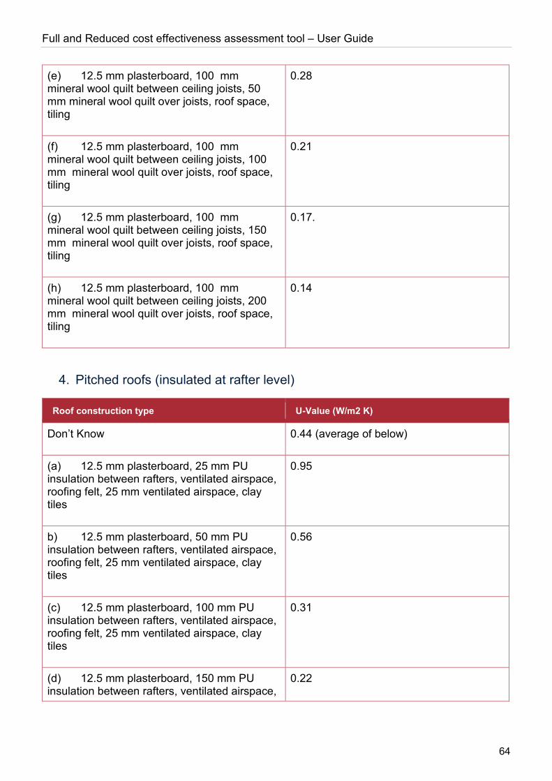
Full and Reduced cost effectiveness assessment tool – User Guide
64
(e) 12.5 mm plasterboard, 100 mm mineral wool quilt between ceiling joists, 50 mm mineral wool quilt over joists, roof space, tiling
0.28
(f) 12.5 mm plasterboard, 100 mm mineral wool quilt between ceiling joists, 100 mm mineral wool quilt over joists, roof space, tiling
0.21
(g) 12.5 mm plasterboard, 100 mm mineral wool quilt between ceiling joists, 150 mm mineral wool quilt over joists, roof space, tiling
0.17.
(h) 12.5 mm plasterboard, 100 mm mineral wool quilt between ceiling joists, 200 mm mineral wool quilt over joists, roof space, tiling
0.14
4. Pitched roofs (insulated at rafter level)
Roof construction type U-Value (W/m2 K)
Don’t Know 0.44 (average of below)
(a) 12.5 mm plasterboard, 25 mm PU insulation between rafters, ventilated airspace, roofing felt, 25 mm ventilated airspace, clay tiles
0.95
b) 12.5 mm plasterboard, 50 mm PU insulation between rafters, ventilated airspace, roofing felt, 25 mm ventilated airspace, clay tiles
0.56
(c) 12.5 mm plasterboard, 100 mm PU insulation between rafters, ventilated airspace, roofing felt, 25 mm ventilated airspace, clay tiles
0.31
(d) 12.5 mm plasterboard, 150 mm PU insulation between rafters, ventilated airspace,
0.22

Full and Reduced cost effectiveness assessment tool – User Guide
65
roofing felt, 25 mm ventilated airspace, clay tiles
(e) 12.5 mm plasterboard, 150 mm PU insulation between rafters and 50 mm over rafters, ventilated airspace, roofing felt, 25 mm ventilated airspace, clay tiles
0.15
5. Sheet metal construction
Roof construction type U-Value (W/m2 K)
Don’t Know 0.35 (average of below)
(a) 0.4 mm inner sheet, 150 mm Z-spacer with MW insulation, 0.7 mm outer sheet
0.35
(b) 0.4 mm inner sheet, 85 mm MW insulation, 40 mm MW insulation between rails, 0.7 mm profiles outer sheet
0.35
Glazing types
The U-values for different glazing types are averages based on values provided in CIBSE (2015) Guide A, Table 3.29 (“U-values for windows”).
Double glazed, air filled
Glazing type spacing U-Value (W/m2 K)
Don’t Know 2.87
6 mm gap 3.10
12 mm gap 2.80
16 mm or greater gap 2.70

Full and Reduced cost effectiveness assessment tool – User Guide
66
Double glazed, air filled, low-E
Glazing type spacing U-Value (W/m2 K)
Don’t Know 2.20
6 mm gap 2.60
12 mm gap 2.10
16 mm or greater gap 1.90
Double glazed, argon filled
Glazing type spacing U-Value (W/m2 K)
Don’t Know 2.73
6 mm gap 2.90
12 mm gap 2.70
16 mm or greater gap 2.60
Double glazed, argon filled, low-E
Glazing type spacing U-Value (W/m2 K)
Don’t Know 2.00
6 mm gap 2.30
12 mm gap 1.90
16 mm or greater gap 1.80

Full and Reduced cost effectiveness assessment tool – User Guide
67
Triple glazed, air filled
Glazing type spacing U-Value (W/m2 K)
Don’t Know 2.17
6 mm gap 2.40
12 mm gap 2.10
16 mm or greater gap 2.00
Triple glazed, air filled, low-E
Glazing type spacing U-Value (W/m2 K)
Don’t Know 1.70
6 mm gap 2.00
12 mm gap 1.60
16 mm or greater gap 1.50
Triple glazed, argon filled
Glazing type spacing U-Value (W/m2 K)
Don’t Know 2.03
6 mm gap 2.20
12 mm gap 2.00
16 mm or greater gap 1.90
Triple glazed, argon filled, low-E
Glazing type spacing U-Value (W/m2 K)
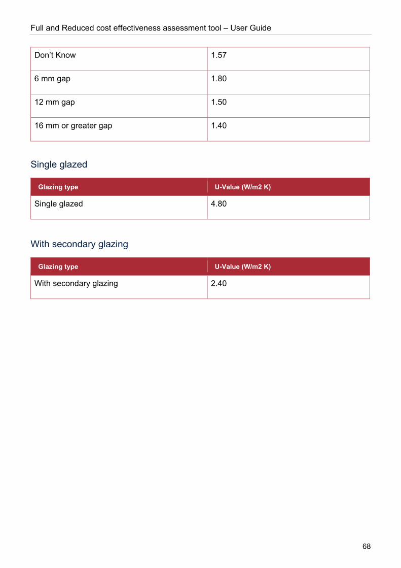
Full and Reduced cost effectiveness assessment tool – User Guide
68
Don’t Know 1.57
6 mm gap 1.80
12 mm gap 1.50
16 mm or greater gap 1.40
Single glazed
Glazing type U-Value (W/m2 K)
Single glazed 4.80
With secondary glazing
Glazing type U-Value (W/m2 K)
With secondary glazing 2.40

This publication is available from: www.gov.uk/beis
If you need a version of this document in a more accessible format, please email [email protected]. Please tell us what format you need. It will help us if you say what assistive technology you use.