Embed Size (px)
Citation preview
19
Metamaterial-Based Compact Filter Design
Merih Palandöken Berlin Institute of Technology
Germany
1. Introduction
Emerging requirements of increasingly complex wireless systems necessitate novel design
methods of wireless components to be developed for the fulfillment of many performance
criteria simultaneously. One of these wireless components to be enhanced for high data rate
transmission systems and matched with the new challenges in new generation
communication systems is the microwave filter. This chapter is mainly dealing with the
novel microwave filter design methods based on artificial materials. How to design
electrically small resonators and to couple each of these resonators with the successive
resonators in a periodic/aperiodic manner in addition to the feeding line for the bandpass
and bandstop filter designs are highlighted throughout this chapter.
In this chapter, because the current trend in filter design is the filter miniaturization for
more compact wireless systems, basic approaches in electrically small filter design based
on artificial metamaterials are explained. The compact resonators result the signal
suppression level of the incoming signal in bandstop filter designs and signal selectivity
of the transmitted signal in bandpass filter designs to be higher as a performance
enhancement. It is due to the target geometrical compactness, resulting into the possibility
of cascading more electrically small resonator cells in a restricted area. Because these
performance parameters are highly related with Q factor of each individual resonator, the
eigenmodes of periodically loaded negative permittivity and negative permeability
resonators are analytically calculated in Section 2. The passband frequencies and Q factor
of the filter to be designed can be engineered with the geometrical and topological
parameters of the resonators, which is the fundamental idea of artificial material based
filter designs. This analytical calculation points out the effect of electromagnetic material
parameters of negative permittivity and permeability materials on filter performance. In
Section 3 and Section 4, two compact filter designs are proposed and explained along with
the numerical results as metamaterial based filter examples. One of these designs is the
fractal resonator based bandstop filter. The other design is the compact bandpass filter
based on thin wire loaded spiral resonator cells. These are quite good examples of
compact filter designs with negative permeability and left-handed metamaterial unit cells,
respectively. These numerically calculated filters points out the compactness and
performance enhancement of novel designs in comparison to the conventional filter
designs in a restricted volume.
www.intechopen.com
Metamaterial
514
2. Theoretical analysis
The motivating principle of theoretical research on LHM is first introduced by Veselago with his theoretical paper in 1968 [Veselago, 1968]. He considered electromagnetic wave propagation through a homogenous isotropic electromagnetic material in which both permittivity and permeability were assumed to have negative real values. Because the direction of the Poynting vector of a monochromatic plane wave is opposite to that of its phase velocity in such a material, he referred to this medium as left-handed medium. This material property makes in turn these materials to support backward-wave propagation due to its negative refractive index. The natural inexistence of such exotic materials had unfortunately led the motivating ideas of Veselago on negative refraction, its various electromagnetic and optical consequences to receive little attention in the scientific community [Engheta & Ziolkowski, 2006; Caloz & Itoh, 2005; Eleftheriades & Balmain, 2005]. However, the work of Pendry on the electromagnetic engineering of magnetic permeability and electric permittivity of the materials with electrically small metallic inclusions has made Veselago’s ideas realisable [Pendry et al.,1999; Pendry et al., 1996]. In 2000, Smith inspired by the work of Pendry and constructed a composite LH medium in the microwave regime by arranging the periodic arrays of small metallic wires and SRRs [Smith & Kroll, 2000]. He demonstrated the anomalous refraction at the interface of this LH medium with the air, which is the result of negative refraction in this artificial material. The effective electromagnetic parameters were also retrieved experimentally and numerically from the transmission and reflection data to prove the negative refractive index [Smith et al., 2005 ; Alexopoulos et al., 2007; Chen et al., 2004 ; Smith et al., 2000]. There have now been several theoretical and experimental studies that have been reported confirming negative refractive index. There are some engineering applications derived from this concept such as phase compensation and electrically small resonators [Engheta, 2002], negative angles of refraction [Kong et al., 2002; Kolinko & Smith, 2003; Ziolkowski, 2003], sub-wavelength waveguides with lateral dimensions below diffraction limits [Alu & Engheta, 2003,2004], enhanced focusing [Grbic & Eleftheriades,2004], backward wave antennas [Grbic & Eleftheriades,2002; Caloz & Itoh, 2005 ], enhanced electrically small antennas [Ziolkowski & Kipple, 2003 ] and compact microwave filters [Marques et al., 2008].
The main principle of negative refractive index in LHMs can be deduced quite easily by the
calculation of TE and TM wave impedances of waveguide modes. The TEmn and TMmn wave
impedances are calculated in a general form as
LHMTEmn
zmn zmn
zmn zmnTMmn
LHM
Zk k
k kZ
ω µωµ
ωε ω ε
= = −
= = −
(1)
with the longitudinal wave number, zmnk at the operation frequency of ω with the magnetic
permeability, µ and electric permittivity, ε of the waveguide filling material. Because the
wave impedance of a passive microwave component is always positive, the phase constant
has to be correspondingly negative in the impedance formulation due to the negative
permittivity and permeability. As a result, the effective refractive index is also negative. This
is an alternative explanation to understand the underlying reasoning why the refractive
www.intechopen.com
Metamaterial-Based Compact Filter Design
515
index has to be negative in the artificial materials with negative permittivity and
permeability. Due to the exploitation of electrically small resonators in the resonator design,
compact resonators can be cascaded to increase the frequency selectivity and stop-band
rejection level in a restricted volume. The accompanying degradation of Q factor due to the
periodic arrangement of intercoupled cells can be compensated by the implementation of
complementary resonators, in which virtual magnetic currents are the excited resonant
sources instead of electrical currents flowing through the lossy metal [Marques et al., 2008].
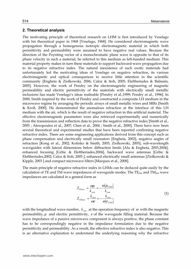
In this chapter, the subwavelength resonance feature of periodically arranged negative permittivity and permeability materials in a rectangular waveguide is explained by the calculation of eigenmode equation for TE modes. The eigenmode calculation can be similarly done for TM modes by replacing TE wave impedance with TM wave impedance in ABCD matrix formulation. The periodically loaded waveguide model is shown in Fig. 1.
Fig. 1. Waveguide model of periodically arranged negative permeability and permittivity materials
ABCD matrix of negative permittivity material of length az1 is formulated with TE-wave impedance, ZH1 and phase constant, kz1 as
1 1 1 1 1
_ 1 11 1
1
cos( ) sin( )
sin( )cos( )
z z H z z
ABCD negeps z zz z
H
k a jZ k a
M k aj k a
Z
=
2 2 21 1 1 ( ) ( )z
m nk
a b
π πω µ ε= − −
(2.a)
11
1
H
z
Zk
ωµ=
where a and b are the waveguide side lengths in x and y directions, respectively.
In the same manner, ABCD matrix of negative permeability material of length az2 is formulated with TE-wave impedance, ZH2 and phase constant, kz2 as
2 2 2 2 2
_ 2 22 2
2
cos( ) sin( )
sin( )cos( )
z z H z z
ABCD negmu z zz z
H
k a jZ k a
M k aj k a
Z
=
www.intechopen.com

Metamaterial
516
2 2 22 2 2 ( ) ( )z
m nk
a b
π πω µ ε= − −
22
2
H
z
Zk
ωµ=
(2.b)
Thus, ABCD matrix of one unit cell of length, az1+az2, consisting of the negative permeability and permittivity materials is calculated by cascading ABCD matrices of the respective materials as
2 22 2 2
1 1 1 1 1
_ 1 122 1 1
21
2
2
2 22 2 2
22
22
2
cos( ) sin( ) cos( ) sin( )2 2sin( )
sin( ) cos( )2 cos( )
2
cos( ) sin( )2 2
sin( )2 cos( )
2
z zz H z
z z H z z
ABCD cell z zzz z z
zH
z
H
z zz H z
zz
zz
H
a ak jZ k k a jZ k a
M k aak j k aa Zj kZ
a ak jZ k
ak
aj k
Z
=
_ABCD cell
A BM
C D
=
(2.c)
where the matrix elements are calculated as in (2.d).
( ) ( )( )
2 11 1 2 2 1 1 2 2
1 2
2 2 2 21 12 1 1 2 2 1 2 1 2 2 2
1
21 11 1 2 2 12
2 1 2
1cos( )cos( ) sin( )sin( )
2
sin( )cos( )sin( ) cos( )
2
1 sin( )cos( )sin( )
2
H Hz z z z z z z z
H H
z zH z z z z H H H H z z
H
z zz z z z H
H H H
Z ZA k a k a k a k a
Z Z
k aB jZ k a k a j Z Z Z Z k a
Z
k aC j k a k a j Z Z
Z Z Z
= − + = + − + +
= + − +( ) ( )( )2 2 22 2 1 2 2
2 11 1 2 2 1 1 2 2
1 2
cos( )
1cos( )cos( ) sin( )sin( )
2
H H H z z
H Hz z z z z z z z
H H
Z Z k a
Z ZD k a k a k a k a
Z Z
+ +
= − +
(2.d)
Thus, the dispersion relation of the periodic array of negative permeability and permittivity
materials is calculated from ABCD parameters to determine the complex propagation
constant, zeffγ as
1 21 2 1 1 2 2 1 1 2 2
2 1
1cosh( ( )) cos( )cos( ) sin( )sin( )
2H H
zeff z z z z z z z z z z
H H
Z Za a k a k a k a k a
Z Zγ
+ = − + (2.e)
This dispersion relation can be formulated in an alternative form for the case of ideal lossless
material parameters as
www.intechopen.com

Metamaterial-Based Compact Filter Design
517
1 21 2 1 1 2 2 1 1 2 2
2 1
1cosh( ( )) cosh( )cosh( ) sinh( )sinh( )
2zeff z z z z z z z z z z
Z Za a a a a a
Z Zγ α α α α
+ = − + (3.a)
with the wave reactances, Z1,2 and attenuation constants, 1,2zα of the negative permittivity
and permeability media, respectively. The wave reactances and attenuation constants are
calculated from (2.a) and (2.b) in the form of
11 1
2 2 21 1
22 2
2 2 22 2
( ) ( )
( ) ( )
H
H
Z jZm n
ja b
Z jZm n
ja b
ωµ
π πω µ ε
ω µ
π πω µ ε
= =
− + +
= = −
+ +
(3.b)
2 2 21 1 1
2 2 22 2 2
( ) ( )
( ) ( )
z
z
m n
a b
m n
a b
π πα ω ε µ
π πα ω ε µ
= + +
= + +
(3.c)
As it is deduced from (3.b), the wave impedances of negative permittivity and permeability materials are inductive and capacitive, respectively. Thus, the wave propagation can be in principle obtained at any frequency by engineering the material parameters and adjusting the slab thicknesses correspondingly to satisfy the resonance condition. Because of the parametric dependence of eigenmode equation on monotonically increasing functions, only one resonance frequency is calculated for a certain phase shift per cell. This results only one frequency band to be obtained in the dispersion diagram for each transversal wave number in the case of lossless material parameters with low material dispersion. This property makes the novel cavity resonators with one resonance frequency for each transversal wave number to be designed by loading the negative permittivity material with the negative permeability material. However, this is not possible in the resonator designs by longitudinal pairing of two RHMs or one RHM with LHM [Engheta & Ziolkowski, 2006].
Another potential application is the design of monomode waveguides with arbitrary thick lateral dimension by loading the waveguide walls with the negative permeability and permittivity materials laterally instead of longitudinally [Alu & Engheta, 2003]. Another important issue is the design of a cavity resonator with negative material parameters at a predetermined resonance frequency, which can be derived from the eigenmode equation. Eigenmode equation indicates that the resonance frequency of a cavity resonator is only dependent on the ratio of each slab thickness rather than the total slab thickness unlike in the conventional resonators [Engheta, 2002]. The same result can also be concluded for the transmission line and resonator designs, which are based on pairing of LH and RH materials in the same unit cell but not of two RH materials. This property leads the compact subwavelength transmission media and resonators to be designed by pairing any slab thicknesses of negative permittivity and permability materials.This is also the main principle in the design of subwavelength guided wave structures with the lateral dimensions below the diffraction limits [Grbic & Eleftheriades,2004].
www.intechopen.com
Metamaterial
518
As a case study, one negative permittivity material of Drude type electric response and one
negative permeability material of Lorentzian type magnetic response are periodically
arranged inside a rectangular waveguide. The slab lengths of negative permittivity and
permeability materials are 1mm and 2mm, respectively. The magnetic resonance, magnetic
plasma frequency and loss parameter are 2.10 GHz, 2.21 GHz and 100 Hz for the negative
permeability material. The electric plasma frequency and loss parameter are 10 GHz and 100
Hz for the negative permittivity material. As deduced from the material parameters, the
material losses are taken into account in the model, however, kept quite small to have low
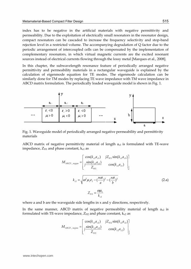
transmission loss and observe the transmission band broadening. The dispersion diagram
and Bloch impedance are analytically calculated and shown in Fig. 2 between the magnetic
resonance and plasma frequencies of the negative permeability medium.
As it is deduced from Fig. 2a, the propagation constant is negative between 2.106 GHz and
2.146 GHz with 40 MHz bandwidth. It results approximately into Q factor of 53 in LH
passband. However, in addition to this LH band, RH band is also obtained between 2.173
GHz and 2.21GHz with 37 MHz bandwidth. This RH passband has an approximate Q factor
of 60 with the center frequency of 2.19GHz. There is 27 MHz bandgap between LH and RH
bands, extending from 2.146 GHz to 2.173 GHz with the highest signal rejection level at the
stop band frequency of 2.16 GHz. The emergence of these two bands is mainly related with
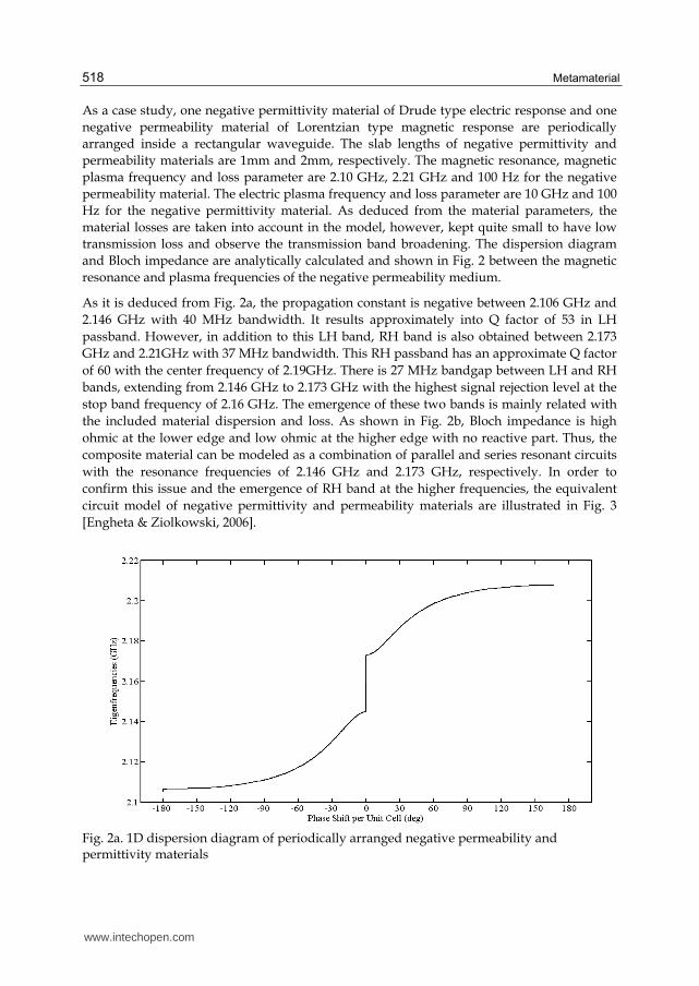
the included material dispersion and loss. As shown in Fig. 2b, Bloch impedance is high
ohmic at the lower edge and low ohmic at the higher edge with no reactive part. Thus, the
composite material can be modeled as a combination of parallel and series resonant circuits
with the resonance frequencies of 2.146 GHz and 2.173 GHz, respectively. In order to
confirm this issue and the emergence of RH band at the higher frequencies, the equivalent
circuit model of negative permittivity and permeability materials are illustrated in Fig. 3
[Engheta & Ziolkowski, 2006].
Fig. 2a. 1D dispersion diagram of periodically arranged negative permeability and permittivity materials
www.intechopen.com
Metamaterial-Based Compact Filter Design
519
Fig. 2b. Resistance (red) and reactance (blue) of periodically arranged negative permeability and permittivity materials
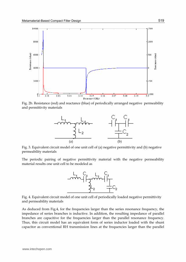
(a) (b)
Fig. 3. Equivalent circuit model of one unit cell of (a) negative permittivity and (b) negative permeability materials
The periodic pairing of negative permittivity material with the negative permeability
material results one unit cell to be modeled as
Fig. 4. Equivalent circuit model of one unit cell of periodically loaded negative permittivity and permeability materials
As deduced from Fig.4, for the frequencies larger than the series resonance frequency, the
impedance of series branches is inductive. In addition, the resulting impedance of parallel
branches are capacitive for the frequencies larger than the parallel resonance frequency.
Thus, this circuit model has an equivalent form of series inductor loaded with the shunt
capacitor as conventional RH transmission lines at the frequencies larger than the parallel
www.intechopen.com
Metamaterial
520
and series resonance frequencies. This is the main reason why this composite material has
an additional RH band at the frequencies larger than the LH band. In a similar manner, the
equivalent circuit model of LH materials can be derived by the investigation of the same
circuit model for the frequencies smaller than the parallel and series resonance frequencies.
For this case, the circuit model has an equivalent form of series capacitor loaded with the
shunt inductor. It is the dual of RH circuit model. One important conclusion from these
circuit models is that the negative permittivity and permeability materials can be
alternatively designed without relying on high lossy resonance phenomenon. In other
words, rather than embedding the electrically small resonant metallic inclusions into the
host material, the left handed feature can also be realized with low loss by periodic loading
of conventional microstrip transmission lines with series capacitors and shunt inductors in
planar microwave technology [Caloz & Itoh, 2005; Eleftheriades & Balmain, 2005]. Many
microwave circuits have been implemented by using this strategy such as compact
broadband couplers [Nguyen & Caloz 2007], broadband phase shifters [Eleftheriades &
Balmain, 2005], compact wideband filters[Gil et al., 2007], compact resonant antennas [Lee et
al., 2005, 2006; Schüßler et al., 2004; Sanada et al. 2004].
3. Spiral fractal resonator based compact band-stop filter
In this section, a compact, low insertion loss, high selective band-stop filter is explained. The filter is composed of two unit cells of electrically small artificial magnetic metamaterials, which have the topological form of fractal spiral resonators in [Palandoken & Henke, 2009]. The geometry of fractal spiral resonators is formed with the direct connection of two concentric Hilbert fractal curves of different dimensions as in a spiral form to excite the magnetic resonance. The operation principle of band-stop filter is based on the excitation of two electrically coupled fractal spiral resonators through direct connection with the feeding line.
The geometry of one unit cell of periodic artificial magnetic material is described shortly in Section 3.1 along with the reflection/transmission parameters and the resonant field pattern at the magnetic resonance frequency. In Section 3.2, the proposed filter topology is depicted with the geometrical and material parameters. The logical approach of the filter design is explained. In Section 3.3, the transmission and reflection parameters are illustrated to verify the desired filter performance and the operation principle is clarified in the light of simulated current distribution at the stopband frequency.
3.1 Structural design of fractal spiral resonator
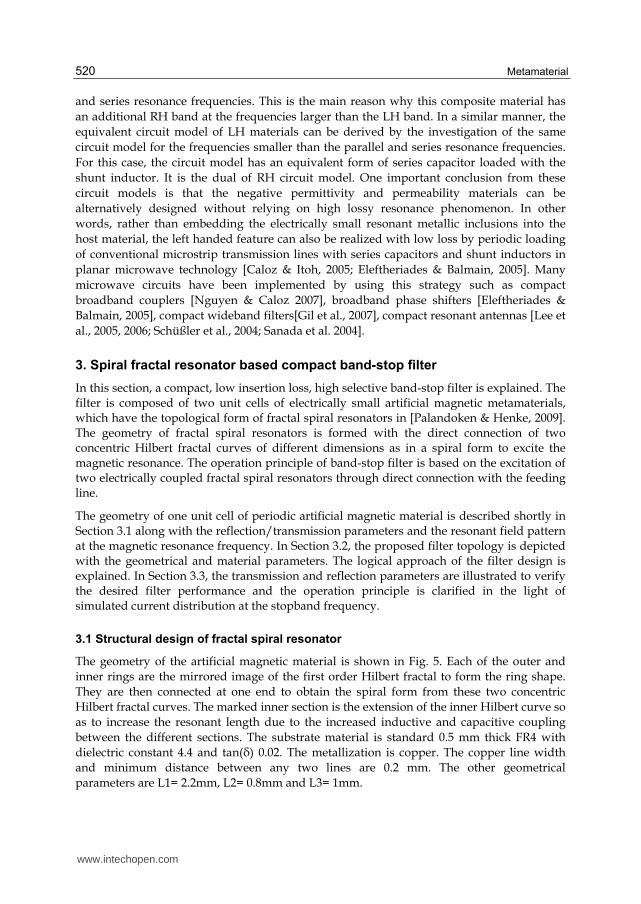
The geometry of the artificial magnetic material is shown in Fig. 5. Each of the outer and
inner rings are the mirrored image of the first order Hilbert fractal to form the ring shape.
They are then connected at one end to obtain the spiral form from these two concentric
Hilbert fractal curves. The marked inner section is the extension of the inner Hilbert curve so
as to increase the resonant length due to the increased inductive and capacitive coupling
between the different sections. The substrate material is standard 0.5 mm thick FR4 with
dielectric constant 4.4 and tan(├) 0.02. The metallization is copper. The copper line width
and minimum distance between any two lines are 0.2 mm. The other geometrical
parameters are L1= 2.2mm, L2= 0.8mm and L3= 1mm.
www.intechopen.com
Metamaterial-Based Compact Filter Design
521
The unit cell size is ax = 5mm, ay =2mm, az = 5mm. Only one side of the substrate is structured with the prescribed fractal geometry while leaving the other side without any metal layer. Because two unit cells of this spiral fractal geometry is excited through the direct connection with the feeding line in the proposed band-stop filter, it is important to verify the magnetic resonance frequency as this frequency is the stopband frequency at which no field transmission is allowed.
Fig. 5. Fractal spiral resonator geometry
In order to induce the magnetic resonance for the determination of stopband frequency, the structure has to be excited with out-off- plane directed magnetic field. Thus, in the numerical model, the structure is excited by z-direction propagating, x-direction polarized plane wave. Perfect Electric Conductor at two x planes and Perfect Magnetic Conductor at two y planes are assigned as the boundary conditions.
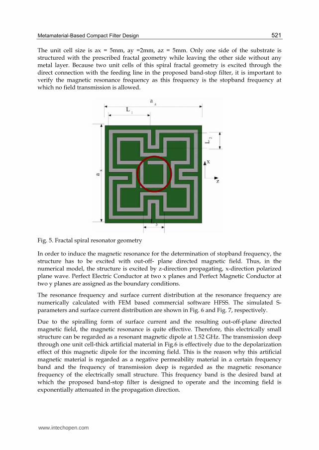
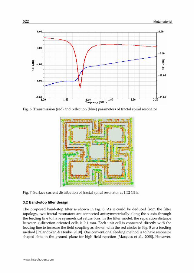
The resonance frequency and surface current distribution at the resonance frequency are
numerically calculated with FEM based commercial software HFSS. The simulated S-
parameters and surface current distribution are shown in Fig. 6 and Fig. 7, respectively.
Due to the spiralling form of surface current and the resulting out-off-plane directed
magnetic field, the magnetic resonance is quite effective. Therefore, this electrically small
structure can be regarded as a resonant magnetic dipole at 1.52 GHz. The transmission deep
through one unit cell-thick artificial material in Fig.6 is effectively due to the depolarization
effect of this magnetic dipole for the incoming field. This is the reason why this artificial
magnetic material is regarded as a negative permeability material in a certain frequency
band and the frequency of transmission deep is regarded as the magnetic resonance
frequency of the electrically small structure. This frequency band is the desired band at
which the proposed band-stop filter is designed to operate and the incoming field is
exponentially attenuated in the propagation direction.
www.intechopen.com
Metamaterial
522
Fig. 6. Transmission (red) and reflection (blue) parameters of fractal spiral resonator
Fig. 7. Surface current distribution of fractal spiral resonator at 1.52 GHz
3.2 Band-stop filter design
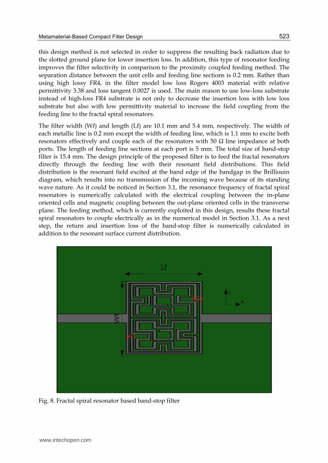
The proposed band-stop filter is shown in Fig. 8. As it could be deduced from the filter
topology, two fractal resonators are connected antisymmetrically along the x axis through
the feeding line to have symmetrical return loss. In the filter model, the separation distance
between x-direction oriented cells is 0.1 mm. Each unit cell is connected directly with the
feeding line to increase the field coupling as shown with the red circles in Fig. 8 as a feeding
method [Palandoken & Henke, 2010]. One conventional feeding method is to have resonator
shaped slots in the ground plane for high field rejection [Marques et al., 2008]. However,
www.intechopen.com
Metamaterial-Based Compact Filter Design
523
this design method is not selected in order to suppress the resulting back radiation due to
the slotted ground plane for lower insertion loss. In addition, this type of resonator feeding
improves the filter selectivity in comparison to the proximity coupled feeding method. The
separation distance between the unit cells and feeding line sections is 0.2 mm. Rather than
using high lossy FR4, in the filter model low loss Rogers 4003 material with relative
permittivity 3.38 and loss tangent 0.0027 is used. The main reason to use low-loss substrate
instead of high-loss FR4 substrate is not only to decrease the insertion loss with low loss
substrate but also with low permittivity material to increase the field coupling from the
feeding line to the fractal spiral resonators.
The filter width (Wf) and length (Lf) are 10.1 mm and 5.4 mm, respectively. The width of each metallic line is 0.2 mm except the width of feeding line, which is 1.1 mm to excite both resonators effectively and couple each of the resonators with 50 Ω line impedance at both ports. The length of feeding line sections at each port is 5 mm. The total size of band-stop filter is 15.4 mm. The design principle of the proposed filter is to feed the fractal resonators directly through the feeding line with their resonant field distributions. This field distribution is the resonant field excited at the band edge of the bandgap in the Brilliouin diagram, which results into no transmission of the incoming wave because of its standing wave nature. As it could be noticed in Section 3.1, the resonance frequency of fractal spiral resonators is numerically calculated with the electrical coupling between the in-plane oriented cells and magnetic coupling between the out-plane oriented cells in the transverse plane. The feeding method, which is currently exploited in this design, results these fractal spiral resonators to couple electrically as in the numerical model in Section 3.1. As a next step, the return and insertion loss of the band-stop filter is numerically calculated in addition to the resonant surface current distribution.
Fig. 8. Fractal spiral resonator based band-stop filter
www.intechopen.com
Metamaterial
524
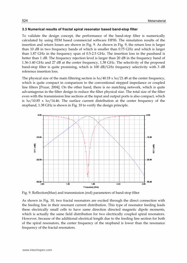
3.3 Numerical results of fractal spiral resonator based band-stop filter
To validate the design concept, the performance of the band-stop filter is numerically
calculated by using FEM based commercial software HFSS. The simulation results of the
insertion and return losses are shown in Fig. 9. As shown in Fig. 9, the return loss is larger
than 10 dB in two frequency bands of which is smaller than 0.75 GHz and which is larger
than 1.87 GHz in the frequency span of 0.5-2.5 GHz. The insertion loss in the passband is
better than 1 dB. The frequency rejection level is larger than 20 dB in the frequency band of
1.36-1.40 GHz and 27 dB at the center frequency, 1.38 GHz. The selectivity of the proposed
band-stop filter is quite promising, which is 100 dB/GHz frequency selectivity with 3 dB
reference insertion loss.
The physical size of the main filtering section is λo/40.18 x λo/21.48 at the center frequency,
which is quite compact in comparison to the conventional stepped impedance or coupled
line filters [Pozar, 2004]. On the other hand, there is no matching network, which is quite
advantageous in the filter design to reduce the filter physical size. The total size of the filter
even with the transmission line sections at the input and output ports is also compact, which
is λo/10.85 x λo/14.46. The surface current distribution at the center frequency of the
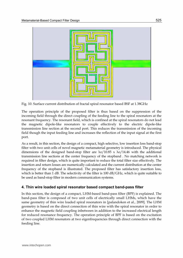
stopband, 1.38 GHz is shown in Fig. 10 to verify the design principle.
Fig. 9. Reflection(blue) and transmission (red) parameters of band-stop filter
As shown in Fig. 10, two fractal resonators are excited through the direct connection with
the feeding line in their resonant current distribution. This type of resonator feeding leads
these electrically small cells to have same direction directed magnetic dipole moments,
which is actually the same field distribution for two electrically coupled spiral resonators.
However, because of the additional electrical length due to the feeding line section for both
of the spiral resonators, the center frequency of the stopband is lower than the resonance
frequency of the fractal resonators.
www.intechopen.com
Metamaterial-Based Compact Filter Design
525
Fig. 10. Surface current distribution of fractal spiral resonator based BSF at 1.38GHz
The operation principle of the proposed filter is thus based on the suppression of the incoming field through the direct coupling of the feeding line to the spiral resonators at the resonant frequency. The resonant field, which is confined at the spiral resonators do not lead the magnetic dipole-like resonators to couple effectively to the electric dipole-like transmission line section at the second port. This reduces the transmission of the incoming field though the input feeding line and increases the reflection of the input signal at the first port.
As a result, in this section, the design of a compact, high selective, low insertion loss band-stop filter with two unit cells of novel magnetic metamaterial geometry is introduced. The physical dimensions of the designed band-stop filter are λo/10.85 x λo/14.46 with the additional transmission line sections at the center frequency of the stopband . No matching network is required in filter design, which is quite important to reduce the total filter size effectively. The insertion and return losses are numerically calculated and the current distribution at the center frequency of the stopband is illustrated. The proposed filter has satisfactory insertion loss, which is better than 1 dB. The selectivity of the filter is 100 dB/GHz, which is quite suitable to be used as band-stop filter in modern communication systems.
4. Thin wire loaded spiral resonator based compact band-pass filter
In this section, the design of a compact, LHM-based band-pass filter (BPF) is explained. The band-pass filter is composed of two unit cells of electrically small LHMs, which have the same geometry of thin wire loaded spiral resonators in [palandoken et al., 2009]. The LHM geometry is based on the direct connection of thin wire with the spiral resonator in order to enhance the magnetic field coupling inbetween in addition to the increased electrical length for reduced resonance frequency. The operation principle of BPF is based on the excitation of two coupled LHM resonators at two eigenfrequencies through direct connection with the feeding line.
www.intechopen.com
Metamaterial
526
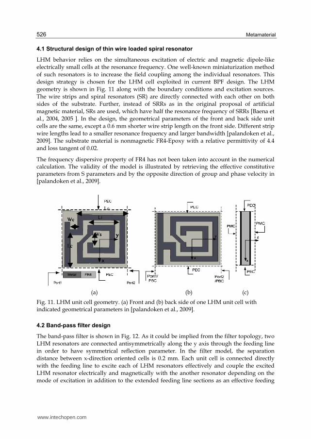
4.1 Structural design of thin wire loaded spiral resonator
LHM behavior relies on the simultaneous excitation of electric and magnetic dipole-like
electrically small cells at the resonance frequency. One well-known miniaturization method
of such resonators is to increase the field coupling among the individual resonators. This
design strategy is chosen for the LHM cell exploited in current BPF design. The LHM
geometry is shown in Fig. 11 along with the boundary conditions and excitation sources.
The wire strips and spiral resonators (SR) are directly connected with each other on both
sides of the substrate. Further, instead of SRRs as in the original proposal of artificial
magnetic material, SRs are used, which have half the resonance frequency of SRRs [Baena et
al., 2004, 2005 ]. In the design, the geometrical parameters of the front and back side unit
cells are the same, except a 0.6 mm shorter wire strip length on the front side. Different strip
wire lengths lead to a smaller resonance frequency and larger bandwidth [palandoken et al.,
2009]. The substrate material is nonmagnetic FR4-Epoxy with a relative permittivity of 4.4
and loss tangent of 0.02.
The frequency dispersive property of FR4 has not been taken into account in the numerical calculation. The validity of the model is illustrated by retrieving the effective constitutive parameters from S parameters and by the opposite direction of group and phase velocity in [palandoken et al., 2009].
(a) (b) (c)
Fig. 11. LHM unit cell geometry. (a) Front and (b) back side of one LHM unit cell with indicated geometrical parameters in [palandoken et al., 2009].
4.2 Band-pass filter design
The band-pass filter is shown in Fig. 12. As it could be implied from the filter topology, two
LHM resonators are connected antisymmetrically along the y axis through the feeding line
in order to have symmetrical reflection parameter. In the filter model, the separation
distance between x-direction oriented cells is 0.2 mm. Each unit cell is connected directly
with the feeding line to excite each of LHM resonators effectively and couple the excited
LHM resonator electrically and magnetically with the another resonator depending on the
mode of excitation in addition to the extended feeding line sections as an effective feeding
www.intechopen.com

Metamaterial-Based Compact Filter Design
527
method. LHM resonator shaped slots in the ground plane are not exploited in the current
band-pass filter due to the resulting back radiation from the slotted ground plane. The
separation distance between one unit cell and feeding line sections in y-direction is 0.8 mm.
One LHM resonator is shifted from the another resonator along y-direction with the
distance of 0.4 mm to obtain optimum field intercoupling. Instead of using high lossy FR4,
in the filter model low loss Rogers 5880 material with the relative permittivity 2.2 and loss
tangent 0.0009 is used. The main reason to use low-loss substrate instead of high-loss FR4
substrate is not only to decrease the insertion loss with low loss substrate but also with low
permittivity material to increase the field coupling from the first resonator into the second
resonator in addition to the field coupling from the feeding line to each of LHM resonators.
Fig. 12. Thin wire loaded spiral resonator based BPF
The lengths of extended feeding line in x- (Lextx ) and y-directions (Lexty ) are 2.5mm and 4.9mm, respectively. The width and length (Lfeed) of feeding line are 1.5mm and 9.8mm, respectively. The direct connection length of the feeding line, (Lextfeed) in the extended sections is 1.9mm. The width and length of Rogers substrate are 30 mm and 24.2mm, respectively. The total size of band-pass filter is 6.4mm x 5.4 mm.
The design principle of the proposed filter is to feed one of the LHM resonators directly
through the feeding line with its resonant field distribution. The highly concentrated field
distribution results the directly excited first resonator to couple to the second LHM
resonator electrically and magnetically depending on the excited 0 and 180 modes. The
excited field in the first LHM resonator is enhanced by the magnetic field of the extended
www.intechopen.com
Metamaterial
528
section of the feeding line. The feeding method, which is currently exploited in this design,
results these LHM resonators to couple feeding line in an optimal manner. As a next step,
the return and insertion loss of the band-pass filter is numerically calculated in addition to
the resonant surface current distribution at two eigenfrequencies.
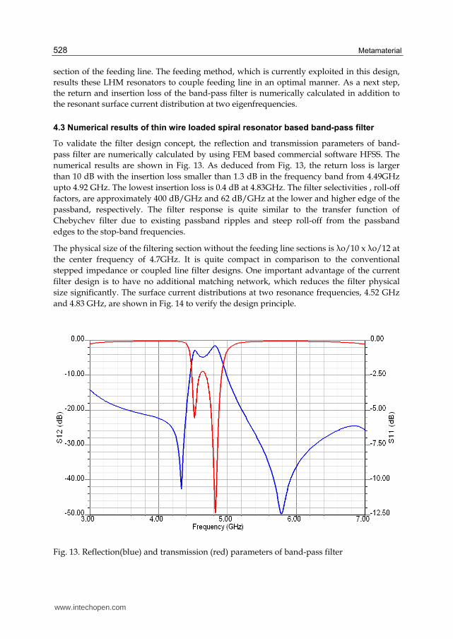
4.3 Numerical results of thin wire loaded spiral resonator based band-pass filter
To validate the filter design concept, the reflection and transmission parameters of band-
pass filter are numerically calculated by using FEM based commercial software HFSS. The
numerical results are shown in Fig. 13. As deduced from Fig. 13, the return loss is larger
than 10 dB with the insertion loss smaller than 1.3 dB in the frequency band from 4.49GHz
upto 4.92 GHz. The lowest insertion loss is 0.4 dB at 4.83GHz. The filter selectivities , roll-off
factors, are approximately 400 dB/GHz and 62 dB/GHz at the lower and higher edge of the
passband, respectively. The filter response is quite similar to the transfer function of
Chebychev filter due to existing passband ripples and steep roll-off from the passband
edges to the stop-band frequencies.
The physical size of the filtering section without the feeding line sections is λo/10 x λo/12 at
the center frequency of 4.7GHz. It is quite compact in comparison to the conventional
stepped impedance or coupled line filter designs. One important advantage of the current
filter design is to have no additional matching network, which reduces the filter physical
size significantly. The surface current distributions at two resonance frequencies, 4.52 GHz
and 4.83 GHz, are shown in Fig. 14 to verify the design principle.
Fig. 13. Reflection(blue) and transmission (red) parameters of band-pass filter
www.intechopen.com
Metamaterial-Based Compact Filter Design
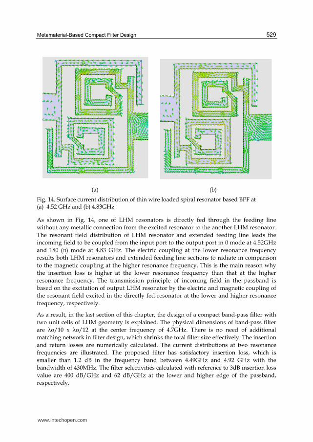
529
(a) (b)
Fig. 14. Surface current distribution of thin wire loaded spiral resonator based BPF at (a) 4.52 GHz and (b) 4.83GHz
As shown in Fig. 14, one of LHM resonators is directly fed through the feeding line
without any metallic connection from the excited resonator to the another LHM resonator.
The resonant field distribution of LHM resonator and extended feeding line leads the
incoming field to be coupled from the input port to the output port in 0 mode at 4.52GHz
and 180 (л) mode at 4.83 GHz. The electric coupling at the lower resonance frequency
results both LHM resonators and extended feeding line sections to radiate in comparison
to the magnetic coupling at the higher resonance frequency. This is the main reason why
the insertion loss is higher at the lower resonance frequency than that at the higher
resonance frequency. The transmission principle of incoming field in the passband is
based on the excitation of output LHM resonator by the electric and magnetic coupling of
the resonant field excited in the directly fed resonator at the lower and higher resonance
frequency, respectively.
As a result, in the last section of this chapter, the design of a compact band-pass filter with
two unit cells of LHM geometry is explained. The physical dimensions of band-pass filter
are λo/10 x λo/12 at the center frequency of 4.7GHz. There is no need of additional
matching network in filter design, which shrinks the total filter size effectively. The insertion
and return losses are numerically calculated. The current distributions at two resonance
frequencies are illustrated. The proposed filter has satisfactory insertion loss, which is
smaller than 1.2 dB in the frequency band between 4.49GHz and 4.92 GHz with the
bandwidth of 430MHz. The filter selectivities calculated with reference to 3dB insertion loss
value are 400 dB/GHz and 62 dB/GHz at the lower and higher edge of the passband,
respectively.
www.intechopen.com
Metamaterial
530
5. References
N. G. Alexopoulos, C. A. Kyriazidou, and H. F. Contopanagos, “Effective parameters for
metamorphic materials and metamaterials through a resonant inverse scattering
approach,” IEEE Trans. Microw. Theory Tech., vol. 55, no. 2, pp. 254–267, Feb.
2007
A. Alù and N. Engheta, “Pairing an epsilon-negative slab with a mu-negative slab:
Resonance, tunneling and transparency,” IEEE Trans. Antennas Propag., vol. 51,
no. 10, pp. 2558–2571, Oct. 2003.
A. Alù and N. Engheta, “Guided modes in a waveguide filled with a pair of
single-negative(SNG), double-negative (DNG), and/or double-positive (DPS)
layers,” IEEE Trans. Microw. Theory Tech., vol. 52, no. 1, pp. 199–210, Jan.
2004.
J. Baena, R. Marqués & F. Medina, “Artificial magnetic metamaterial design by using spiral
resonators,” Phy. Rev. B, vol. 69, pp. 0144021–0144025, 2004
C.Caloz and T. Itoh, Electromagnetic Metamaterials: Transmission Line Theory and Microwave
Applications, Piscataway, NJ: Wiley- IEEE, 2005
X. Chen, T. M. Grzegorczyk, B.-I.Wu, J. Pacheco, Jr., and J. A. Kong, “Robust method to
retrieve the constitutive effective parameters of metamaterials,” Phys. Rev. Lett. E,
vol. 70, pp. 0166081–0166087, 2004.
G. V. Eleftheriades and K. G. Balmain, Negative Refraction Metamaterials: Fundamental
Principles and Applications, New York:Wiley Interscience, 2005
N. Engheta, “An idea for thin subwavelength cavity resonators using metamaterials with
negative permittivity and permeability,” IEEE Antennas Wireless Propag. Lett., vol.
1, no. 1, pp. 10–13, 2002
N. Engheta and R. W. Ziolkowski, Metamaterials Physics and Engineering Explorations, Eds.
New York: Wiley/IEEE, 2006.
M. Gil, J. Bonache, J. Garcia-Garcia, J. Martel & F. Martin, “Composite right/left-handed
metamaterial transmission lines based on complementary split-rings resonators
and their applications to very wideband and compact filter design,” IEEE Trans.
Microw. Theory Tech., vol. 55, no. 6, pp. 1296–1304, Jun. 2007.
A. Grbic and G. V. Eleftheriades, “Overcoming the diffraction limit with a planar
left- handed transmission lines,” Phys. Rev. Lett., vol. 92, no. 11, p. 117 403, Mar.
2004.
A. Grbic and G. V. Eleftheriades, “Experimental verification of backward-wave radiation
from a negative refractive index metamaterial,” J.Appl. Phys., vol. 92, pp. 5930–
5935, Nov. 2002.
P. Kolinko and D. R. Smith, “Numerical study of electromagnetic waves interacting
with negative index materials,” Opt. Express, vol. 11, pp. 640–648, Apr.
2003
J. A. Kong, B.-I. Wu, and Y. Zhang, “A unique lateral displacement of a Gaussian beam
transmitted through a slab with negative permittivity and permeability,”
Microwave Opt. Technol. Lett., vol. 33, pp. 136–139, Mar. 2002.
www.intechopen.com
Metamaterial-Based Compact Filter Design
531
C.-J. Lee, K. M. K. H. Leong, and T. Itoh, “Composite right/left-handed transmission line
based compact resonant antennas for RF module integration,” IEEE Trans. Antennas
Propag., vol. 54, no. 8, pp. 2283–2291, Aug. 2006.
C.-J. Lee, K. M. K. H. Leong, and T. Itoh, “Design of resonant small antenna using composite
right/left handed transmission line,” in Antennas Propag. Soc. Int. Symp., 2005, vol.
2B
Ricardo Marqués, Ferran Martín, Mario Sorolla, Metamaterials with negative parameter:theory,
design, and microwave applications, John Wiley & Sons, 2008
H. V. Nguyen and C. Caloz, “Generalized coupled-mode approach of metamaterial coupled
line couplers: Coupling theory, phenomenological explanation and experimental
demonstration,” IEEE Trans. Microw.Theory Tech., vol. 55, no. 5, pp. 1029–1039, May
2007
M. Palandöken, A. Grede & H. Henke, “Broadband microstrip antenna with Left-
handedMetamaterials, ”IEEE Trans. Antennas Propag., vol. 57, no.2, pp. 331–338,
Feb. 2009
M. Palandöken, H. Henke, “Fractal spiral resonator as magnetic metamaterial, ”Applied
Electromagnetics Conference, pp. 1–4, 2009
M. Palandöken, H. Henke, “Compact LHM-based band-stop filter”, Mediterranean
Microwave Symposium, pp. 229–231, Aug. 2010
J. B. Pendry, A. J. Holden, D. J. Robbins & W. J. Stewart, “Magnetism from conductors and
enhanced nonlinear phenomena,” IEEE Trans. Microw. Theory Tech., vol. 47, no.
11, pp. 2075–2081, Nov. 1999
J. B. Pendry, A. J. Holden, D. J. Robbins & W. J. Stewart, “Low-frequency plasmons in thin
wire structures,” J. Phys., Condens.Matter, vol. 10, pp. 4785–4809, 1998
David Pozar, Microwave Engineering , 2004, Wiley
A. Sanada, M. Kimura, I. Awai, C. Caloz, and T. Itoh, “A planar zeroth- order resonator
antenna using a left handed transmission line,” in 34th Eur. Microw. Conf.,
Amsterdam, The Netherlands, 2004, pp. 1341–1344.
M. Schüßler, J. Freese, and R. Jakoby, “Design of compact planar antennas using LH-
transmission lines,” in Proc. IEEE MTT-S Int. Microw. Symp., 2004, vol. 1, pp. 209–
212.
D. R. Smith and N. Kroll, “Negative refractive index in left-handed materials,” Phys. Rev.
Lett., vol. 85, pp. 2933–2936, Oct. 2000.
D. R. Smith, D. C. Vier, N. Kroll, and S. Schultz, “Direct calculation of permeability and
permittivity for a left- handed metamaterial,” App.Phys. Lett., vol. 77, no. 14, pp.
2246–2248, Oct. 2000
D. R. Smith, D. C. Vier, T. Koschny, and C. M. Soukoulis, “Electromagnetic parameter
retrieval from inhomogeneous metamaterials,” Phys. Rev. E, vol. 71, pp. 0366171–
03661711, 2005
R.W. Ziolkowski and A. Kipple, “Application of double negative metamaterials to increase
the power radiated by electrically small antennas,” IEEE Trans. Antennas Propag.,
vol. 51, no. 10, pp. 2626–2640, Oct. 2003
R. W. Ziolkowski, “Pulsed and CW Gaussian beam interactions with double negative
metamaterial slabs,” Opt. Express, vol. 11, pp. 662–681, Apr. 2003
www.intechopen.com

Metamaterial
532
V. G. Veselago, “The electrodynamics of substances with simultaneously negative values of
┝ and µ,” Sov. Phys.—Usp., vol. 47, pp. 509–514, Jan.–Feb. 1968.
www.intechopen.com
MetamaterialEdited by Dr. Xun-Ya Jiang
ISBN 978-953-51-0591-6Hard cover, 620 pagesPublisher InTechPublished online 16, May, 2012Published in print edition May, 2012
InTech EuropeUniversity Campus STeP Ri Slavka Krautzeka 83/A 51000 Rijeka, Croatia Phone: +385 (51) 770 447 Fax: +385 (51) 686 166www.intechopen.com
InTech ChinaUnit 405, Office Block, Hotel Equatorial Shanghai No.65, Yan An Road (West), Shanghai, 200040, China
Phone: +86-21-62489820 Fax: +86-21-62489821
In-depth analysis of the theory, properties and description of the most potential technological applications ofmetamaterials for the realization of novel devices such as subwavelength lenses, invisibility cloaks, dipole andreflector antennas, high frequency telecommunications, new designs of bandpass filters, absorbers andconcentrators of EM waves etc. In order to create a new devices it is necessary to know the mainelectrodynamical characteristics of metamaterial structures on the basis of which the device is supposed to becreated. The electromagnetic wave scattering surfaces built with metamaterials are primarily based on theability of metamaterials to control the surrounded electromagnetic fields by varying their permeability andpermittivity characteristics. The book covers some solutions for microwave wavelength scales as well asexploitation of nanoscale EM wavelength such as visible specter using recent advances of nanotechnology, forinstance in the field of nanowires, nanopolymers, carbon nanotubes and graphene. Metamaterial is suitable forscholars from extremely large scientific domain and therefore given to engineers, scientists, graduates andother interested professionals from photonics to nanoscience and from material science to antennaengineering as a comprehensive reference on this artificial materials of tomorrow.
How to referenceIn order to correctly reference this scholarly work, feel free to copy and paste the following:
Merih Palandoken (2012). Metamaterial-Based Compact Filter Design, Metamaterial, Dr. Xun-Ya Jiang (Ed.),ISBN: 978-953-51-0591-6, InTech, Available from:http://www.intechopen.com/books/metamaterial/metamaterial-based-compact-filter-design

© 2012 The Author(s). Licensee IntechOpen. This is an open access articledistributed under the terms of the Creative Commons Attribution 3.0License, which permits unrestricted use, distribution, and reproduction inany medium, provided the original work is properly cited.