Embed Size (px)
Citation preview

Metallurgical Failures in Oil and Gas Pipelines
By Dr Jonathan Sykes
Asia Offshore Energy Conference
The Intercontinental Hotel, Jimbaran, Indonesia
September 2012

Introduction
1. Why investigate the cause of pipe failures?
2. How do pipelines fail?
3. How are the failures investigated?

Burgoynes
ASSOCIATED OFFICES WORLD-WIDE
Dr J. H. Burgoyne & Partners LLPUK
Burgoyne IncorporatedAtlanta, USA
Dr J. H. Burgoyne & Partners (International) Ltd
Singapore
Dr J. H. Burgoyne & Partners (International) Ltd
Hong Kong
Dr JH Burgoyne & Partners (Int’l) Ltd
Singapore Office
+65 6225 9011
Hong Kong Office
+852 2526 6731

Marine Pipeline Incidents by Reported Cause- Gulf of Mexico (Total 916 incidents)
Corrosion49%
Material Failure10%
Maritime Activity14%
Storms12%
Other or unknown15%
Pipeline Failures
Source: Woodson R.D. 1991. A Critical Review of Offshore Pipeline Failures

Pipeline Failures
Source: Parloc 2001: The update of Loss of Containment Data for Offshore Pipelines
Maritime Pipeline Incidents by Reported Cause- North Sea (Total 64 Leaks)
Corrosion40%
Material Failure17%
Maritime Activity26%
Storms0%
Other or unknown17%
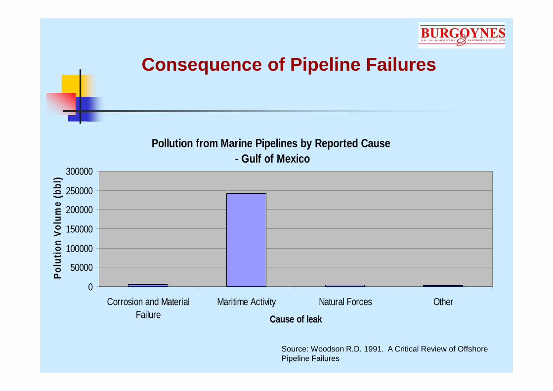
Consequence of Pipeline Failures
Pollution from Marine Pipelines by Reported Cause - Gulf of Mexico
0
50000
100000
150000
200000
250000
300000
Corrosion and MaterialFailure
Maritime Activity Natural Forces Other
Cause of leak
Pol
utio
n V
olum
e (b
bl)
Source: Woodson R.D. 1991. A Critical Review of Offshore Pipeline Failures

Consequence of Pipeline Failures
“In the early afternoon of 3 June 2008 a high pressure 12 inch export sales gas pipeline (SGL), critically weakened by a region of external corrosion, ruptured and exploded on the beach of VaranusIsland off the coast of Western Australia.
………There was approximately A$60 million in damage to the plant. Plant closure led to up to A$3 billion of losses to the WA economy which lost 30 per cent of its gas supply for two months.”
Source: Offshore PetroleumSafety Regulation, Varanus Island Incident Investigation

Consequences of Pipe Failures- Costs
• Various techniques for repairing leaks:
• Clamps
• Sleeves
• Cutting out and welding in place new pipe sections.
• In shallow water repairs can be performed by divers. In deeper waters ROVs must be used.
• Loss of fluid transport capacity due to shutdown of the line
Source: DET NORSKE VERITAS RECOMMENDED PRACTICE: DNV-RP-F113 PIPELINE SUBSEA REPAIR

Causes of Pipeline Failures
• Corrosion
• External
• Internal
• Mechanical Failure
• Fatigue
• Buckling

Corrosion
Corrosion is an electrochemical process that results in dissolution and loss (wastage) of metals such as steel.
(i) An anodic reaction, which generates electrons:
2Fe (metallic iron) → 2Fe2+ (dissolved iron) + 4e- (electrons)
The passage of positive charge from metal to solution produced by the above reaction is balanced by the passage of negative charge from solution to metal at sites termed
cathodes:
(ii) A cathodic reaction, which consumes electrons:
(iia) O2 + 4e- + 2H2O → 4OH-
or
(iib) 4H+ + 4e- → 2H2

Corrosion
Fe2+
Electrons
O or H2
+
OH or H
Fe
-2

Corrosion Morphology
METAL SUBSTRATE
Corrosion wastage
Original Metal Surface
Fe
Fe Fe2+
+ 2e
2+
-
2e-
OH O2 2 OH-
O + H O + 2e = 2OH2 2
2
- -
ANODE
CATHODE
12
General Corrosion
• Discrete anode and cathode sites reverse their polarity rapidly, causing metal loss over the entire surface at relatively uniform rates
• Readily measurable so often considered a “safe” form of corrosion
Pitting Corrosion
• Discrete anodes at the metal surface, due to the presence of an irregularity at the metal surface or within the metal structure.
•Penetration can be rapid
•Difficult to detect and can therefore lead to perforation of the pipe.

External Corrosion
• External corrosion occurs due to exposure to seawater. The rate of corrosion is dependent upon availability of dissolved oxygen.
• Corrosion is largely general corrosion, leading to uniform wastage at a rate of about 0.15mm/year.
• Pitting corrosion can lead to localised penetration at rates of 1.0mm/year
Fe2+
Electrons
O or H2
+
OH or H
Fe
-2

External Corrosion Protection
• Primary method of protecting the external surfaces of pipes is by the use of a coating.
•The coating should form a continuous barrier to isolate the metal from direct contact with the surrounding corrosive environment.
• The most common type of coating is Fusion Bonded Epoxy (FBE). When this coating is damaged it chips off and does not form a crevice.
• Heat the pipe to 250oC
• Apply FBE as a powder to hot surface
• Epoxy flows and cures
• Quench

External Corrosion Protection
• All coatings contain defects where high rates of corrosion can occur.
• Paint coating usually used in combination with cathodic protection.
• Technique involves the supply of electrons to the surface to “replace” electrons generated by pipe corrosion.
• Sacrificial anodes
• Impressed current from a generator.
• Cathodic protection protects only the external surface.

External Corrosion Protection
Anode
Pipe
4 Al12 e
12 OH
3 O + 6H O
+
2 2

External Corrosion Protection

External Corrosion Protection
Pipe
4 OH
O + 2H O2 2
Anode2Cl
4Cl
2
DC Power Supply

Internal Corrosion
Internal corrosion is influenced by several factors:
• The composition of the fluid:
• free water,
• carbon dioxide (CO2)
• hydrogen sulphide (H2S)
• Flow velocity and temperature of the fluids within the pipeline.
• Entrained solids within the fluids.

Internal Corrosion-Flow Rate
• Oil transported in pipelines contains water. Even after it passes through separators there will be some suspended microdroplets.
• The entrained water can wet the internal surface if there is insufficient flow through the pipe. Minimum required flow rate to prevent water wetting is considered to be about 1m/s
Droplets of water suspended in the oil flow
Droplets coalesce At high velocity water entrained within the oil flow
At low velocities wetting of the pipe surface occurs

Internal Corrosion-Carbon Dioxide
• Carbon dioxide is highly soluble in water and produces an acid in solution.
• Corrosion by the acid causes a film of corrosion product to form at the metal surface that protects the underlying steel.

Internal Corrosion-Carbon Dioxide
• If the iron carbonate film is not continuous then localised corrosion can occur, leading to rapid pitting.
Source: Subsea Pipeline Engineering 2nd edition: A.C. Palmer & R.A. King

Prevention of carbon dioxide corrosion
• Pipelines can be protected from carbon dioxide corrosion by the use of inhibitors
• Inhibitors promote the formation of an iron carbonate film at the internal surface of the pipe.
• To provide uninterrupted corrosion protection the inhibitor must be added continuously at an adequate concentration.

Preferential weld corrosion in an offshore flowline
• Leaks occurred in flowlines from the wellhead to a production manifold in an offshore platform.
• Carbon steel pipeline contained gas, condensate and water.
• Gas stream had a 1 mol% concentration of CO2.
• Corrosion inhibitor injected into flowlines. Operators had difficulty maintaining required level of inhibitor in the system

Internal Corrosion- Hydrogen Sulfide
Wet gas that contains hydrogen sulfide is said to be “sour” and can be very damaging to pipelines.
• Pitting Corrosion
• Sulphide Stress Cracking
• Hydrogen Induced Cracking
Source: Mitigation of Internal Corrosion in Sour Gas Pipeline Systems: Canadian Association of Petroleum Producers: June 2009

Internal Corrosion- Hydrogen Sulfide Pitting
• The presence of hydrogen sulphide causes and iron sulphide film to form.
•At breaks in the film rapid pitting can occur.

Internal Corrosion- Hydrogen Sulfide (Sulfide Stress Cracking)
TENSILE
STRESS
SUSCEPTIBLE
MATERIAL
CORROSIVE
ENVIRONMENT
SCC
• A form of stress corrosion cracking caused by the conjoint action of stress and a corrosive environment.
• High strength steels are susceptible to cracking. If conditions are known to be sour then steels with a hardness in excess of 250HV should be avoided.

Sulfide Stress Cracking
• Sections of pipe were replaced due to internal pitting corrosion
• It was specified that the replacement pipe should be resistant to SSC as it was known that it carried sour gas.
• Leak occurred at a weld
• Investigation found that the hardness of the weld was higher than specified and would have been susceptible to SSC

Internal Corrosion- Hydrogen Sulfide (Hydrogen Induced Cracking)
• When corrosion occurs in H2S, atomic hydrogen is produced which diffuses into the steel.
• The hydrogen accumulates at inclusions in the steels and combines to form hydrogen gas. The gas forms blisters that cause the steel to crack.

Internal Corrosion- Entrained Solids
Sand Production
0
5
10
15
20
25
30
35
40
Month
San
d P
rod
uct
ion
• Solids entrained in the fluid erode protective films that form at the internal surface.
• Effects more severe at pipe bends and other areas of turbulent flow.
• If sand cannot be avoided, designers should incorporate large diameter bends in pipe runs.

Mechanical Failure Mechanisms- Fatigue fracture
• Fatigue is a progressive cracking mechanism caused by cyclic stresses.

Mechanical Failure Mechanisms- Fatigue fracture
• Oil and gas pipes are susceptible to cyclic loading and fatigue cracking at connections to reciprocating pumps and compressors that induce vibration.
• Pipe lengths can also suffer fatigue cracking during transport, prior to installation. This is termed transit fatigue. Cracks are only discovered after installation

Mechanical Failure Mechanisms- Fatigue fracture
• Newly installed section of pipe leaked during hydrotest. Leak originated at a spiral weld.
• Review of the mill records indicated that:
• The weld had been ultrasonic tested for cracks
• The pipe section had been successfully hydrotested at the mill.
• The pipe sections had been transported by road over 110km, 30km of which was on gravel road.
Source: “Pipeline Failure by Transit Fatigue””””, Mohammed A. Al-Anezi, Sanyasi Rao and Dr. Graham R. Lobley; Saudi Aramco Journal Of Technology Winter 2008

Mechanical Failure Mechanisms- Fatigue fracture
• Cracks originated at the toes of the welds at both the inside and outside of the pipe.
• Cracks had propagated by a mechanism of fatigue.
•Cyclic stresses generated by repeated deformation of the pipe as it was transported over uneven ground.

Mechanical Failure Mechanisms- Localised Pipe buckling
• Localised buckling of pipes is the collapse of the pipe cross-section due to bending or external pressure.
• The collapse of the cross-section can lead to fracture of the pipe.
• Pipes are susceptible to buckling during pipe laying.
• Susceptibility to buckling is increased if there are step changes in wall thickness or misalignment of welds.
Investigation of Pipeline Failures

Metallurgical Investigation

Radiography
Source: http://www.ndt-ed.org/EducationResources/CommunityCollege/Radiography/TechCalibrations/RadiographInterp.htm

Magnetic Particle Inspection

Laboratory Examination and Testing to Determine Failure Modes
• Where components have fractured, the fracture surface should be examined using a Scanning Electron Microscope (SEM). Different failure modes have different fracture features.

Laboratory Examination and Testing to Determine Failure Modes
• Chemical analyses on deposits, corrosion scales can assist in determining whether any aggressive environments led to failure.
•Chemical analyses on and materials of manufacture to ensure that they conformed to specified requirements.

Laboratory Examination and Testing to Determine Failure Modes
• Mechanical testing to determine the properties of materials of construction

Investigation of Pipeline Failures
• Interview relevant personnel to determine circumstances of incident.
• Review relevant records:
• Installation drawings
• Inspection reports
• Analysis results
• Carry out metallurgical examination and testing
• Formulate conclusions based on evidence as a whole

Summary
• Failures of pipelines occur frequently
• Catastrophic failures are rare but they do occur.
• Whilst failure might not lead to a substantial leak they can be expensive to rectify.
• It is important to determine the cause of the failure to establish liability and to determine future risk