Embed Size (px)
Citation preview
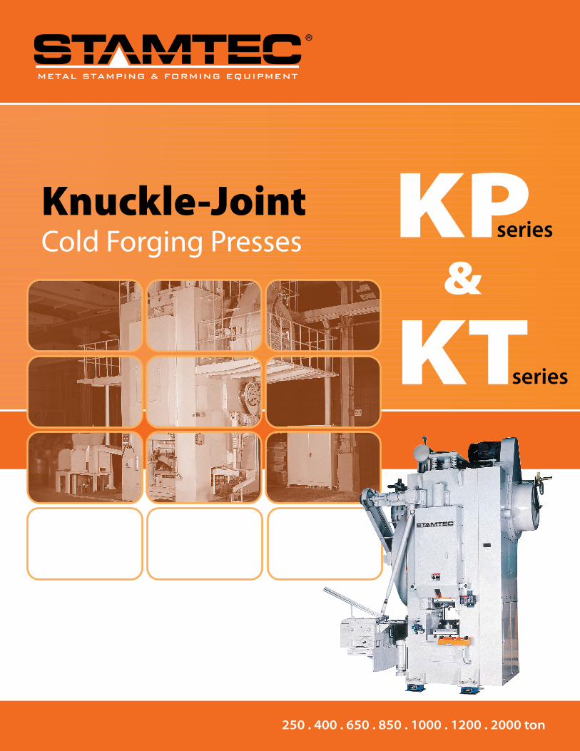
Knuckle-JointCold Forging Presses
250 . 400 . 650 . 850 . 1000 . 1200 . 2000 ton
KW2 SERIES
HIGH PRECISIONPROGRESSIVE
KW1 SERIES
COLD ANDSEMI-HOT
KT SERIES
AUTO TRANSFERRING
KP SERIES
1-POINT
U.S.A. - STAMTEC, INC.
4160 Hillsboro Highway | Manchester, TN 37355 U.S.A.
TEL: +1-931-393-5050 | FAX: +1-931-393-5060 | www.stamtec.com
Stamtec has been providing dependable, affordably priced metal stamping presses for almost 30 years in the North American market, and 60 years worldwide through our parent company Chin Fong. Our 72,000 sq. ft. sales, service, logistics, and assembly facility in Tennessee is home not only to North America's largest inventory of new presses and spare parts, but also our most important asset - our people. Our staff of engineering, sales, service, and support personnel are here to serve you in the most timely and professional manner. So, tap into our global strength, and grow with us as we grow with you! KP
&
KT
series
series
METAL STAMPING & FORMING EQUIPMENTMETAL STAMPING & FORMING EQUIPMENT
METAL STAMPING & FORMING EQUIPMENT

72
KP SERIESKnuckle-Joint 1-Point Cold Forging Presses
OUTLINE DIMENSIONS
MODEL
KP-250 KP-400 KP-650 KP-850 KP-1000 KP-1200 KP-2000
A 1650 1700 1900 2140 2750 3050 2950
B 1000 1250 1500 1500 1720 2000 3200
C 3015 3540 4150 4340 5155 6075 7080
D 500 550 600 600 700 800 1000
E 3850 4500 5060 5460 6234 7280 8000
F 400 400 450 450 480 800 800
G 570 590 700 700 820 1000 1300
H 700 820 1000 1030 1300 1455 2030
I 490 560 560 580 660 850 730
J 1530 1570 1750 1990 2590 2890 2450
K 780 950 1100 1100 1270 1500 2900
L 1850 2125 2460 2735 3160 3450 5470
M 2100 2640 3095 3420 4980 5060 6480
KP-2000 Knuckle-Joint Press
K Knuckle Joint Series
The KL, KP, KT, and KW2 forging presses are specially designed for cold forging and are ideal for near net-shape forming. The cold forge technology forms steel components without cutting metal fibers, giving the product a more consistent and durable strength.
Tonnage Range: 250-2,000
Stamtec Cold Forge Technology
Stamtec cold forging press technology provides particular advantages for producing steel components, improving strength and consistency. Near net shape forming, improved mechanical characteristics, superior plasticity, higher surface quality, and increased productivity are just some of the benefits of cold forging presses.
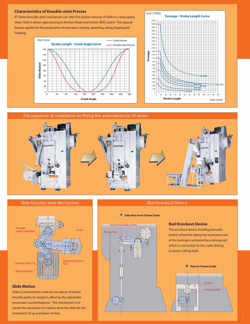
Characteristics of Knuckle-Joint PressesKT Series Knuckle-Joint mechanism can alter the motion velocity of Slide to a slow speed
when Slide is driven approaching to Bottom Dead-end Center (BDC) point. This special
feature applies for the production of extrusion, coining, upsetting, sizing, forging and
heading.
Crank Angle
Slid
e M
oti
on
Unit: (mm)
Stroke Length - Crank Angle CurveCrank Presses
Knuckle-Joint Presses
Tonnage - Stroke Length CurveUnit: (TONS)
Unit: (mm)Stroke Length
Ton
nag
e
The sequence of installation for fitting the automations to KP series
Slide Knuckle-Joint Mechanism Bed Knockout Device
Slide MotionSlide is connected to crank by two pieces of linked
knuckle joints; its weight is offset by the adjustable
pneumatic counterbalancer. This mechanism is to
transit the revolution of crank to drive the slide for the
movement of up and down strokes.
Bed Knockout DeviceThe knockout device installing beneath
bolster of bed for taking the work-piece out
of the toolings is activated by a driving rod,
which is connection to the crank-driving
eccentric rolling shaft.
Side View from Frame Outer
View to Frame Inside

3
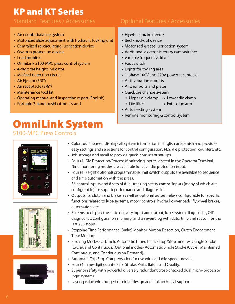
KP and KT SeriesStandard Features / Accessories Optional Features / Accessories
6
• Air counterbalance system• Motorized slide adjustment with hydraulic locking unit• Centralized re-circulating lubrication device• Overrun protection device• Load monitor• OmniLink 5100-MPC press control system• 4-digit die height indicator• Misfeed detection circuit• Air Ejector (3/8”)• Air receptacle (3/8”)• Maintenance tool kit• Operating manual and inspection report (English)• Portable 2-hand pushbutton t-stand
• Flywheel brake device• Bed knockout device• Motorized grease lubrication system• Additional electronic rotary cam switches• Variable frequency drive• Foot switch• Lights for tooling area• 1-phase 100V and 220V power receptacle• Anti-vibration mounts• Anchor bolts and plates• Quick die change system » Upper die clamp » Lower die clamp » Die lifter » Extension arm• Auto feeding system• Remote monitoring & control system
OmniLink System5100-MPC Press Controls
• Color touch screen displays all system information in English or Spanish and provides easy settings and selections for control configuration, PLS, die protection, counters, etc.• Job storage and recall to provide quick, consistent set-ups.• Four (4) Die Protection/Process Monitoring inputs located in the Operator Terminal. Nine monitoring modes are available for each die protection input.• Four (4), (eight optional) programmable limit switch outputs are available to sequence and time automation with the press.• 56 control inputs and 8 sets of dual-tracking safety control inputs (many of which are configurable) for superb performance and diagnostics.• Outputs for clutch and brake, as well as optional output relays configurable for specific functions related to lube systems, motor controls, hydraulic overloads, flywheel brakes, automation, etc.• Screens to display the state of every input and output, lube system diagnostics, OIT diagnostics, configuration memory, and an event log with date, time and reason for the last 256 stops.• Stopping Time Performance (Brake) Monitor, Motion Detection, Clutch Engagement Time Monitor• Stroking Modes- Off, Inch, Automatic Timed Inch, Setup/StopTime Test, Single Stroke (Cycle), and Continuous. (Optional modes- Automatic Single Stroke (Cycle), Maintained Continuous, and Continuous on Demand).• Automatic Top Stop Compensation for use with variable speed presses.• Four (4) nine-digit counters for Stroke, Parts, Batch, and Quality.• Superior safety with powerful diversely redundant cross-checked dual micro-processor logic systems• Lasting value with rugged modular design and Link technical support
SPECIFICATIONS
Type KP-250 KP-400 KP-650 KP-850 KP-1000 KP-1200 KP-2000
Main Specifi cations S V S V S V S V S V S V S V
Capacity Tons 250 400 650 850 1000 1200 2000
Rated tonnage point mm 4 6 8 8 8 8 8
Stroke length mm 120 160 160 180 160 250 180
Strokes per minute S.P.M. Continuos 40 30-50 32 25-40 30 25-35 30 25-35 30 25-35 25-35 22-32
Die height (S.D.A.U.) mm 370 400 400 400 500 600 550
Maximum upper die weight kg 500 800 1000 1000 1200 1200 1200
Bolster area (L-R x F-B) mm 500 x 600 550 x 660 600 x 700 600 x 700 700 x 800 800 x 1000 1000 x 800
Slide area (L-R x F-B) mm 400 x 420 400 x 500 450 x 550 450 x 550 480 x 650 800 x 800 800 x 700
Slide adjustment mm 15 15 15 15 15 15 15
Bolster thickness mm 100 120 150 180 180 200 250
Air Pressure Requirement kg/cm2 5 5 5 5 5 5 5
Main motor HP 20 25 40 50 50 75 75 75100
Bed knockout device
Capacity Tons 10 15 30 30 50 50 80
Stroke length mm 50 60 70 70 70 100 80
2 / 3 Axis transfer unit
Model KTF-3-14530 KTF-3-170 KTF-3-200
Feed pitch mm 145 170 200
Clamping stroke mm 35 35 60
Lifting stroke mm 15 15 20
Inner distance between feeds mm 110 110 270
Stokes per minute S.P.M. 40 40 30
Feeding direction (front - to - rear) front - to - rear left - to - right
100 100 150
METAL STAMPING & FORMING EQUIPMENT

54
KT SERIESKnuckle-Joint Auto-Transferring Presses
SPECIFICATIONS
Press Advantages
Slide is connected to crankshaft by a linked knuckle mechanism that modifies the motion of the slide, achieving a mechanical advantage and dwell that supplies very high tonnage near the bottom of the stroke.
OUTLINE DIMENSIONS
KT-800 Knuckle-Joint Press
MODEL
KT-400 KT-650 KT-800 KT-1000
A 2100 2500 3250 3400
B 1620 1850 2250 2250
C 4215 4830 6070 6205
D 700 800 1100 1100
E 5250 5952 7220 7040
F 700 800 1080 1080
G 920 1050 1350 1350
H 1050 1200 1250 1300
I 730 730 900 920
J 1900 2300 3090 3240
K 1270 1450 1800 1800
L 2240 2505 3275 3410
M 4510 4750 5305 5345
Hydraulic Slide Locking Device Main Motor
Counterbalancer
Transmission Gearboxand Brake Device
Take-off Shaftand Gearbox
Main Driven Drviceof Transfer Unit*
Bed Knockout Device
Hydraulic Slide Locking Device
Auxiliary Driven Deviceof Transfer Unit
METAL STAMPING & FORMING EQUIPMENT
Type KT-400 KT-650 KT-800 KT-1000
Main Specifi cations
Capacity Tons 400 650 800 1000
Rated tonnage point mm 8 8 8 8
Stroke length mm 180 180 250 250
Strokes per minute S.P.M. Continuous 25-40 25-35 25-35 25-35
Die height (S.D.A.U.) mm 550 550 650 400
Bolster area (L-R x F-B x T.) mm 700 x 700 x 120 800 x 800 x 150 1100 x 800 x 170 1100 x 800 x 180
Slide area (L-R x F-B) mm 680 x 700 780 x 800 1080 x 800 1080 x 800
Slide open (F-B x H.) mm 500 x 500 550 x 630 700 x 730 700 x 730
Slide adjustment mm 15 15 15 15
Air Pressure Requirement kg/cm2 5 5 5 5
Main motor HPXP V.S.50X4 V.S.100X4 V.S.100X4 V.S.125X4
Bed Knockout Device
Capacity Tons 10 x 3 = 30 15 x 3 = 45 12 x 5 = 60 12 x 5 = 60
Stroke length mm 60 70 70 70
3-Axis Transfer Unit
Model VTF-170 VTF-200 VTF-200 VTF-200
Feed pitch mm 170 200 200 200
Clamping stroke mm 50 60 60 60
Lift stroke mm 20 20 25 25
Inner distance of feed bars mm 240 270 360 360
Feed line height mm 270 300 300 300
Strokes per minute S.P.M. 30 30 30 30
Feed bar sectional profi le mm 70 x 70 75 x 80 100 x 100 100 x 100
Feed direction (left to right) Left to Right
3
KP and KT SeriesStandard Features / Accessories Optional Features / Accessories
6
• Air counterbalance system• Motorized slide adjustment with hydraulic locking unit• Centralized re-circulating lubrication device• Overrun protection device• Load monitor• OmniLink 5100-MPC press control system• 4-digit die height indicator• Misfeed detection circuit• Air Ejector (3/8”)• Air receptacle (3/8”)• Maintenance tool kit• Operating manual and inspection report (English)• Portable 2-hand pushbutton t-stand
• Flywheel brake device• Bed knockout device• Motorized grease lubrication system• Additional electronic rotary cam switches• Variable frequency drive• Foot switch• Lights for tooling area• 1-phase 100V and 220V power receptacle• Anti-vibration mounts• Anchor bolts and plates• Quick die change system » Upper die clamp » Lower die clamp » Die lifter » Extension arm• Auto feeding system• Remote monitoring & control system
OmniLink System5100-MPC Press Controls
• Color touch screen displays all system information in English or Spanish and provides easy settings and selections for control configuration, PLS, die protection, counters, etc.• Job storage and recall to provide quick, consistent set-ups.• Four (4) Die Protection/Process Monitoring inputs located in the Operator Terminal. Nine monitoring modes are available for each die protection input.• Four (4), (eight optional) programmable limit switch outputs are available to sequence and time automation with the press.• 56 control inputs and 8 sets of dual-tracking safety control inputs (many of which are configurable) for superb performance and diagnostics.• Outputs for clutch and brake, as well as optional output relays configurable for specific functions related to lube systems, motor controls, hydraulic overloads, flywheel brakes, automation, etc.• Screens to display the state of every input and output, lube system diagnostics, OIT diagnostics, configuration memory, and an event log with date, time and reason for the last 256 stops.• Stopping Time Performance (Brake) Monitor, Motion Detection, Clutch Engagement Time Monitor• Stroking Modes- Off, Inch, Automatic Timed Inch, Setup/StopTime Test, Single Stroke (Cycle), and Continuous. (Optional modes- Automatic Single Stroke (Cycle), Maintained Continuous, and Continuous on Demand).• Automatic Top Stop Compensation for use with variable speed presses.• Four (4) nine-digit counters for Stroke, Parts, Batch, and Quality.• Superior safety with powerful diversely redundant cross-checked dual micro-processor logic systems• Lasting value with rugged modular design and Link technical support
SPECIFICATIONS
Type KP-250 KP-400 KP-650 KP-850 KP-1000 KP-1200 KP-2000
Main Specifi cations S V S V S V S V S V S V S V
Capacity Tons 250 400 650 850 1000 1200 2000
Rated tonnage point mm 4 6 8 8 8 8 8
Stroke length mm 120 160 160 180 160 250 180
Strokes per minute S.P.M. Continuos 40 30-50 32 25-40 30 25-35 30 25-35 30 25-35 25-35 22-32
Die height (S.D.A.U.) mm 370 400 400 400 500 600 550
Maximum upper die weight kg 500 800 1000 1000 1200 1200 1200
Bolster area (L-R x F-B) mm 500 x 600 550 x 660 600 x 700 600 x 700 700 x 800 800 x 1000 1000 x 800
Slide area (L-R x F-B) mm 400 x 420 400 x 500 450 x 550 450 x 550 480 x 650 800 x 800 800 x 700
Slide adjustment mm 15 15 15 15 15 15 15
Bolster thickness mm 100 120 150 180 180 200 250
Air Pressure Requirement kg/cm2 5 5 5 5 5 5 5
Main motor HP 20 25 40 50 50 75 75 75100
Bed knockout device
Capacity Tons 10 15 30 30 50 50 80
Stroke length mm 50 60 70 70 70 100 80
2 / 3 Axis transfer unit
Model KTF-3-14530 KTF-3-170 KTF-3-200
Feed pitch mm 145 170 200
Clamping stroke mm 35 35 60
Lifting stroke mm 15 15 20
Inner distance between feeds mm 110 110 270
Stokes per minute S.P.M. 40 40 30
Feeding direction (front - to - rear) front - to - rear left - to - right
100 100 150
METAL STAMPING & FORMING EQUIPMENT
72
KP SERIESKnuckle-Joint 1-Point Cold Forging Presses
OUTLINE DIMENSIONS
MODEL
KP-250 KP-400 KP-650 KP-850 KP-1000 KP-1200 KP-2000
A 1650 1700 1900 2140 2750 3050 2950
B 1000 1250 1500 1500 1720 2000 3200
C 3015 3540 4150 4340 5155 6075 7080
D 500 550 600 600 700 800 1000
E 3850 4500 5060 5460 6234 7280 8000
F 400 400 450 450 480 800 800
G 570 590 700 700 820 1000 1300
H 700 820 1000 1030 1300 1455 2030
I 490 560 560 580 660 850 730
J 1530 1570 1750 1990 2590 2890 2450
K 780 950 1100 1100 1270 1500 2900
L 1850 2125 2460 2735 3160 3450 5470
M 2100 2640 3095 3420 4980 5060 6480
KP-2000 Knuckle-Joint Press
K Knuckle Joint Series
The KL, KP, KT, and KW2 forging presses are specially designed for cold forging and are ideal for near net-shape forming. The cold forge technology forms steel components without cutting metal fibers, giving the product a more consistent and durable strength.
Tonnage Range: 250-2,000
Stamtec Cold Forge Technology
Stamtec cold forging press technology provides particular advantages for producing steel components, improving strength and consistency. Near net shape forming, improved mechanical characteristics, superior plasticity, higher surface quality, and increased productivity are just some of the benefits of cold forging presses.
Characteristics of Knuckle-Joint PressesKT Series Knuckle-Joint mechanism can alter the motion velocity of Slide to a slow speed
when Slide is driven approaching to Bottom Dead-end Center (BDC) point. This special
feature applies for the production of extrusion, coining, upsetting, sizing, forging and
heading.
Crank Angle
Slid
e M
oti
on
Unit: (mm)
Stroke Length - Crank Angle CurveCrank Presses
Knuckle-Joint Presses
Tonnage - Stroke Length CurveUnit: (TONS)
Unit: (mm)Stroke Length
Ton
nag
e
The sequence of installation for fitting the automations to KP series
Slide Knuckle-Joint Mechanism Bed Knockout Device
Slide MotionSlide is connected to crank by two pieces of linked
knuckle joints; its weight is offset by the adjustable
pneumatic counterbalancer. This mechanism is to
transit the revolution of crank to drive the slide for the
movement of up and down strokes.
Bed Knockout DeviceThe knockout device installing beneath
bolster of bed for taking the work-piece out
of the toolings is activated by a driving rod,
which is connection to the crank-driving
eccentric rolling shaft.
Side View from Frame Outer
View to Frame Inside

Knuckle-JointCold Forging Presses
250 . 400 . 650 . 850 . 1000 . 1200 . 2000 ton
KW2 SERIES
HIGH PRECISIONPROGRESSIVE
KW1 SERIES
COLD ANDSEMI-HOT
KT SERIES
AUTO TRANSFERRING
KP SERIES
1-POINT
U.S.A. - STAMTEC, INC.
4160 Hillsboro Highway | Manchester, TN 37355 U.S.A.
TEL: +1-931-393-5050 | FAX: +1-931-393-5060 | www.stamtec.com
Stamtec has been providing dependable, affordably priced metal stamping presses for almost 30 years in the North American market, and 60 years worldwide through our parent company Chin Fong. Our 72,000 sq. ft. sales, service, logistics, and assembly facility in Tennessee is home not only to North America's largest inventory of new presses and spare parts, but also our most important asset - our people. Our staff of engineering, sales, service, and support personnel are here to serve you in the most timely and professional manner. So, tap into our global strength, and grow with us as we grow with you! KP
&
KT
series
series
METAL STAMPING & FORMING EQUIPMENTMETAL STAMPING & FORMING EQUIPMENT
METAL STAMPING & FORMING EQUIPMENT