Embed Size (px)
Citation preview

Metal-plate connections loaded in combined bending and tension
Ronald W. Wolfe
Abstract This study evaluates the load capacity of metal-plate
connections under combined bending and axial loads and shows the reduction in connection tensile capacity with an increase in applied moment. Five load categories, includ- ing pure axial tension, pure bending, and three interme- diate levels of combined loading, were applied to joints fabricated using one plate type in southern pine 2 by 4 lumber. Each joint was tested to failure and the axial and or moment load at the connection was evaluated on the basis of its fraction of pure axial and or moment capa- city. A tension-bending interaction equation was derived to represent the observed interaction response of these connections.
Metal-plate connections (MPCs) used primarily for the fabrication of light-frame wood trusses, are normally not assumed to provide moment resistance. An MPC is some- times checked for moment, but the check is usually made independent of any axial load. Truss design standards do not require moment checks, and test standards do not include test procedures to evaluate the moment capacity of MPCs.
Although the test and design standards dealing with MPCs do not address their resistance to bending moments, the problem of transferring bending stresses has been rec- ognized at the research level (13, 15, 16). Tests of trusses and truss assemblies (22) have shown that connection be- havior has a major influence on assembly performance. Some test results (8, 15) suggest that bending moments have a significant effect on the axial load capacity of MPCs. If so, this effect must be considered in character- izing ultimate load capacity of any assembly constructed using MPCs. Analytical models have been developed to recognize bending rigidity of connections (10, 13). Some of these models enable simulation of the nonlinear bend- ing behavior of MPCs on the basis of standard axial load test results. The assessment of modeling accuracy, how- ever, is limited by the knowledge base. While model esti-
mates of joint axial and moment capacity, made with no actual test verification, may provide support for engineer- ing judgment, such estimates must be used with caution.
This report summarizes a study conducted to provide a preliminary assessment of the importance of tension- bending interaction on joint capacity and a limit state model to be used as a failure criterion for truss and truss assembly model evaluations.
Literature review Structural performance of MPCs has received exten-
sive research attention over the past 20 years. The pri- mary use of these connectors is in the fabrication of light- frame wood trusses, for which the connections are rarely assumed to carry moment. As a result, most truss-plate research has focused on performance under axial load (12, 17, 19) and how these connections are affected by various test and environmental variables (5, 6, 11, 14). A few re- searchers (9, 13, 15, 18, 20), evaluating moment capacity of MPCs, have shown limited success at modeling the mo- ment rotation curves up to the point of plate buckling or gap closure, but little information is available that can be used to set limit states for MPCs subject to combined axial and bending loads.
A number of standards have been developed for the evaluation of the strength and stiffness of MPCs. The American Society for Testing and Materials (ASTM) main- tains several standards that deal directly with these con- nections (2-4). The Canadian Standard Association (CSA) also publishes a truss-plate test standard (7). None of these test standards provide guidelines for testing the moment capacity of MPCs.
A computer model proposed by Foschi (9) provides a means of evaluating moment and axial load capacity. His
The author is a Research Engineer, USDA Forest Serv., For- est Prod. Lab., One Gifford Pinchot &., Madison, WI 53705-2398. This paper was received for publication in September 1989. © Forest Products Research Society 1990.
Forest Prod. J. 40(9):17-23.
FOREST PRODUCTS JOURNAL Vol. 40. No. 9 17
model uses parameters derived on the basis of four stan- dard axial test configurations described by the CSA stan- dard (7). A number of studies have been conducted that focus on the derivation of these parameters for various species of wood and plate configurations (9, 12, 20). How- ever, the true accuracy of this model for predicting mo- ment capacity has not been established.
Few data are Available to characterize the performance of MPCs under combined tension and bending. The inter- action equation presented by Zahn (23-25) to characterize wood member load capacity under combined axial and bending loads provides a model format that is easily used to define a failure limit state. The Foschi (9) MPC model may be used to predict joint performance well into the elasto-plastic range, but some judgment is needed to de- fine ultimate load capacity. Preliminary analysis of MPCs using this model and the assumption that connection ca- pacity may be defined as the point at which the joint stiff- ness is 10 percent of its initial value suggest that an inter- action equation of a format similar to that proposed by Zahn could also be used for modeling limit states of plated connections.
More information is needed to accurately evaluate the load capacity of MPCs. Current tests and design standards focus only on axial load capacity. Available models that have the capacity to trace a plate load slip or moment rotation curve into the plastic range cannot identify the plate failure without better data on joint limit states. To establish the needed database, a standard method for test- ing and analyzing connection capacity under combined loading must be developed.
Objectives and scope This paper was written as part of a study conducted
to develop a test procedure that could be used to evaluate the capacity of MPCs subjected to combined tension and bending loads. The parent study included the design and evaluation of a set of eccentric loading grips and a series of tests on MPCs to characterize load interaction behavior. The grips were designed specifically for 2 by 4 lumber and 20-gauge metal connector plates characteristic of ma- terials used for light-frame floor and roof trusses. Test methods and results are discussed, and a preliminary in- teraction equation is presented. Design details and an assessment of the loading grip will be discussed in a fu- ture paper.
Methods Tests conducted to determine the capacity of MPCs
under combined load included tests of the constituent ma- terials and tests of the plated connections. Material tests included the determination of wood modulus of elasticity (MOE), specific gravity (SG), strength of the plate steel, and net section strength of the plates. MPCs were tested in axial tension, pure bending, and at three levels of com- bined tension and bending. The combined loads were ap-
1 The use of trade or firm names in this publication is for reader information and does not imply endorsement by the U.S. De- partment of Agriculture of any product or service.
18
plied as an eccentrically applied axial load with three dis- crete levels of eccentricity.
Tests were confined to one joint configuration. The metal-plate connector used was a 3- by 5.25-inch 20-gauge plate with a tooth density of 9 teeth per square inch. The wood used was a medium density southern pine. Twenty- four teeth were removed around the centerline of each plate. This left two groups of 60 teeth separated by a gap of 1.12 inches. The plates were then pressed symmetri- cally with respect to the joint, giving a total of 120 effec- tive teeth per member (60 teeth per side).
Data analysis methods focused on the axial load and moment at the location of the MPC. Under pure axial and pure bending, loads were assumed to be uniformly distrib- uted over the length of the specimen between load points. For combined loading, secondary moment effects were ac- counted for on the basis of member end rotation and cen- terline deflection.
The effect of combined load was evaluated by fitting a line to the plot of the axial load ratio and comparing it to the bending load ratio at the point of maximum load.
Sample preparation All test samples were fabricated and conditioned in
the same manner. For 2 weeks prior to sample fabrication, the lumber was stored in a 12 percent moisture content (MC) conditioning room. Each 14-foot-long piece was num- bered and tested for MOE using an E-Computer 1 that de- termined MOE on the basis of vibration frequency. Each piece was then cut into three 50-inch-long samples and marked to note location along the original piece. Next, a 1-inch-long MC and SG block was cut from the center of each sample, leaving two end-matched pieces 24-3/8 inches long to be joined with an MPC to form the test specimen. All specimens were cut to avoid knots in the area of the end joint. In the case of specimens to be tested in tension or combined tension and bending, care was also taken to avoid knots in the area of the grip attachment. Ten- sile forces were transferred to the specimens through a 2-5/8-inch-diameter shear plate embedded in the surface of the 2 by 4. A 3/4-inch-diameter hole was drilled in the center of this grooved area for the bolt used to transfer load from the test machine to the shear plate.
The pieces were tightly butted and held in alignment to produce test specimens that were straight with no gap. MPCs were pressed one at a time to full uniform contact between plate and wood, one side at a time to keep the specimen straight. After fabrication, the specimens were again placed in a conditioning room where temperature and relative humidity were controlled to give an equilib- rium MC of 12 percent. They remained in this room for at least 12 days prior to testing.
Test procedures Tests were conducted to determine mechanical prop-
erties of individual materials and those of the connections. Material tests included strength tests of the metal plates, stiffness tests of the lumber, SG, and MC evaluations for the joint samples. Connection tests included evaluations of load displacement and capacity at five different levels of combined loading.
The plate tests included steel coupon tests following
SEPTEMBER 1990

ASTM E 8 (1) standard test procedure for tension testing of metallic materials and net section tests of the connec- tor plate following ASTM E 489-81 (3) standard test pro- cedure for tensile strength properties of steel truss plates.
Tests of the MPCs under combined loading were con- ducted using a screw-type test machine to apply an eccen- tric axial load. The rate of head movement was controlled to give a constant strain rate. For axial tension and com- bined axial/bending tests, a strain rate of 0.035 in./min. was used, resulting in failure in about 5 minutes for each test. The bending tests were conducted at 0.05 in./min. in about the same time to failure. Load application
Special test grips (Fig. 1) were used to apply combined axial and bending loads to the MPCs. The grips were de- signed to apply axial load through pin connections at the centroid on each end of a 2 by 4 test specimen and to apply moment through a transverse couple with a 7.9-inch arm placed symmetrically around the centroid loading pin.
The magnitude of the couple was controlled by varying the eccentricity of the load applied to the grips. The grip was designed to provide three discrete load eccentricities, 7/8 inch, 2-5/8 inches, and 9-7/8 inches. These values were selected on the basis of preselected ratios of axial tension to bending moment to be applied at the centerline of a 48-inch-long 2 by 4 specimen at maximum load. The ana- lytical model used to derive these values assumed uniform section and elasticity properties over the length of the specimen, a member MOE of 1.5 × 10 6 psi, and a linear interaction relationship with a maximum tension capacity of 10,000 pounds and a maximum moment capacity of 14,000 in.-lb. These axial and moment capacities were
Figure 1. — Test grip design showing the three loading lugs, the pivot point, the rotation reference point, and the bearing plates used to transfer moment and axial tension to the ends of a 2 by 4 test spec- imen.
pilot test results. Assume an interaction limit state equa- tion of the form:
Rp + Rm = 1 where:
Rp = ratio of applied axial load to pure axial load ca-
Rm = ratio of applied moment to pure bending capac-
Target load ratios were initially set to give Rp/Rm of 0.75/0.25, 0.5/0.5, and 0.25/0.75. However, the analytical model used to evaluate eccentricity indicated that a 0.25- inch eccentricity would be needed to give a bending stress of 25 percent of the maximum at the time axial load was 75 percent of its maximum. An eccentricity this small created a number of design problems. As a result, the ec- centricities used for the test setup (Fig. 2) were more heav- ily weighted on the bending moment side, giving ratios of about 0.5/0.5, 0.2/0.8, and 0.1/0.9 for Rp/Rm at ultimate load.
In addition to the combined load tests, samples were also tested in pure axial tension and pure bending. The axial tension tests used a pin connection through a shear plate centered on each end of a 4-foot specimen with an MPC at midlength (Fig. 3). The pure bending test was conducted using a two-point load on a 44-inch span, to give a constant moment section 26 inches long containing the MPC (Fig. 4).
Pilot tests conducted to evaluate the grip-load capacity showed a tendency for tension perpendicular failures to occur as a result of radial bearing forces along the circum- ference of the shear plate. This was only a problem for
pacity
ity
FOREST PRODUCTS JOURNAL Vol. 40, No. 9 19
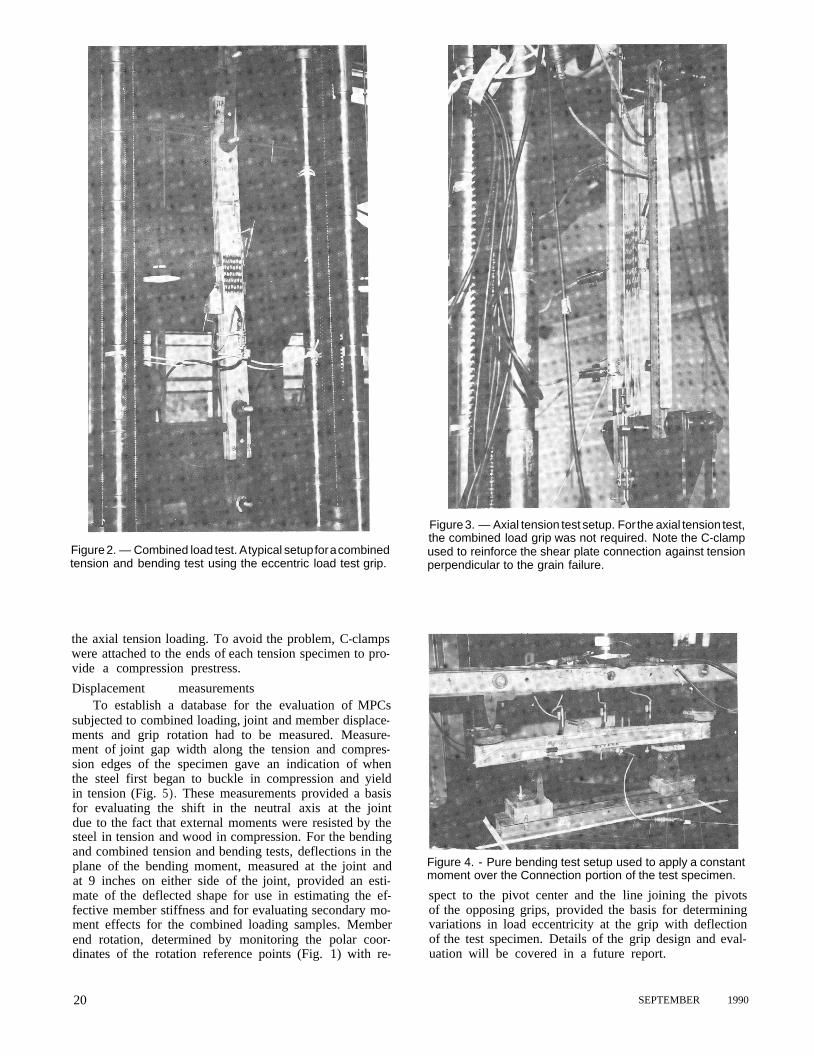
Figure 3. — Axial tension test setup. For the axial tension test, the combined load grip was not required. Note the C-clamp
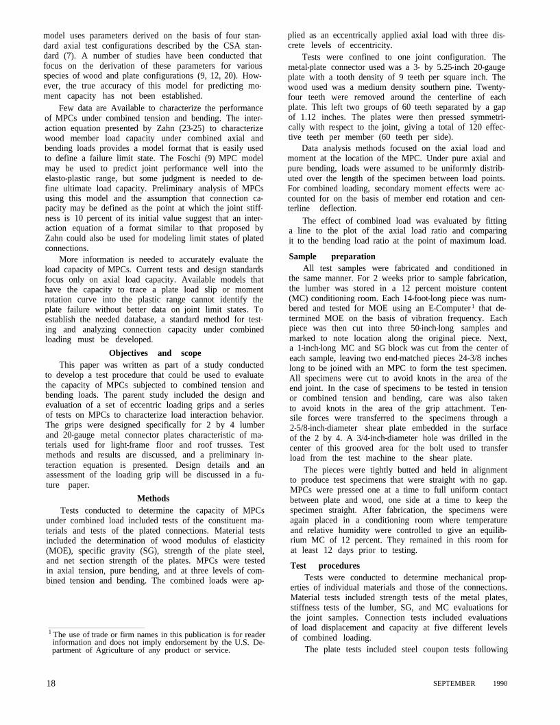
Figure 2. — Combined load test. A typical setup for a combined tension and bending test using the eccentric load test grip.
used to reinforce the shear plate connection against tension perpendicular to the grain failure.
the axial tension loading. To avoid the problem, C-clamps were attached to the ends of each tension specimen to pro- vide a compression prestress. Displacement measurements
To establish a database for the evaluation of MPCs subjected to combined loading, joint and member displace- ments and grip rotation had to be measured. Measure- ment of joint gap width along the tension and compres- sion edges of the specimen gave an indication of when the steel first began to buckle in compression and yield in tension (Fig. 5). These measurements provided a basis for evaluating the shift in the neutral axis at the joint due to the fact that external moments were resisted by the steel in tension and wood in compression. For the bending and combined tension and bending tests, deflections in the plane of the bending moment, measured at the joint and at 9 inches on either side of the joint, provided an esti- mate of the deflected shape for use in estimating the ef- fective member stiffness and for evaluating secondary mo- ment effects for the combined loading samples. Member end rotation, determined by monitoring the polar coor- dinates of the rotation reference points (Fig. 1) with re-
Figure 4. - Pure bending test setup used to apply a constant moment over the Connection portion of the test specimen.
spect to the pivot center and the line joining the pivots of the opposing grips, provided the basis for determining variations in load eccentricity at the grip with deflection of the test specimen. Details of the grip design and eval- uation will be covered in a future report.
20 SEPTEMBER 1990

Results Table 1 gives average ultimate axial load and mo-
ments measured for each group of test specimens along with the average MC and SG of the lumber in each group. The axial loads were read directly from the test; however, the bending moments were determined on the basis of the initial eccentricity, the rotation of the grip, and the center- line deflection of the test specimen. All samples had an MC in the range of 12 ± 1 percent at the time of joint fabrication. Connector steel
Steel coupon tests on a solid section (0.5 in. wide by 0.04 in. thick) all failed at loads between 1,050 and 1,070 pounds, averaging 2,120 lb./in. of width. Net section tests of the MPCs (3 in. wide by 0.04 in. thick by 2 sides) all failed between 6,000 and 7,100 pounds, averaging 1,090 lb./in. of width. Based on these tests, the “effectiveness ratio” (21) for these plates is 0.51. The net cross section for the plates was estimated to be 0.061 in.2
Pure axial tension and bending Maximum loads for the axial tests ranged from 6,130
pounds to 7,360 pounds and averaged 6,700 pounds as shown in Table 1. Bending moment capacity ranged from 7,870 to 9,470 in.-lb. and averaged 8,680 in.-lb.
For the axial tests, 8 of the 20 specimens failed due to yielding of the steel, and the rest failed due to tooth pullout. Those that failed due to tooth pullout had a slight- ly lower maximum load (9%) than those that failed due to steel yield.
All bending tests failed due to steel yield. In every case, the compression edge strands buckled and the ten- sion edge strands were strained to failure. Signs of yield- ing were apparent in the fourth strand from the tension edge at the maximum moment.
Strain in the edge steel strand at maximum load, in- dicated by the measurement of gap opening, appeared to be fairly consistent for all tests. Gap opening averaged 0.061 inch for the axial tests and 0.078 inch for the bend- ing tests. For the axial tests that failed due to tooth pull- out, the gap width opening at maximum load was not sig- nificantly greater than that measured on specimens with steel failure. Combined tension and bending
Average bending moment and axial load values for the three specimen types with combined tension and bend- ing are given in Table 1. Maximum axial loads averaged
Figure 5. — Gap measurement. Two linear variable differential transducers were placed on opposite ends of the diagonal at the test joint to measure gap opening. These measurements were used to evaluate effects of stress distribution in the MPC.
TABLE 1. — Test results for various levels of combined axial tension and pure bending load on metal-plate connections.
Target
Rp/Rm a of tests Load COV b ratio c Moment cov ratio MC SG
Lumber Moment ratio Number Axial Axial Bending
(lb.) (%) (in.-lb.) (%) 1/0 20 6,700 6 1.00 0 0 0 12 0.46
0.5/0.5 10 4,800 7 0.72 3,330 9 0.39 12 0.50 0.2/0.8 10 2,530 5 0.38 6,040 3 0.58 12 0.50 0.1/0.9 12 940 5 0.14 7,110 5 0.82 12 0.64
0/1 10 0 0 0 8,680 6 1.00 12 0.46 a Rp = ratio of applied axial load to pure axial load capacity; Rm is the ratio of applied moment to pure bending capacity. b Coefficient of variation. c Axial and moment ratios refer to the ratio of the average axial load and/or bending moment on the joint at the point of failure to strength of samples tested in pure tension or pure bending, respectively.
FOREST PRODUCTS JOURNAL Vol. 40, No. 9 21
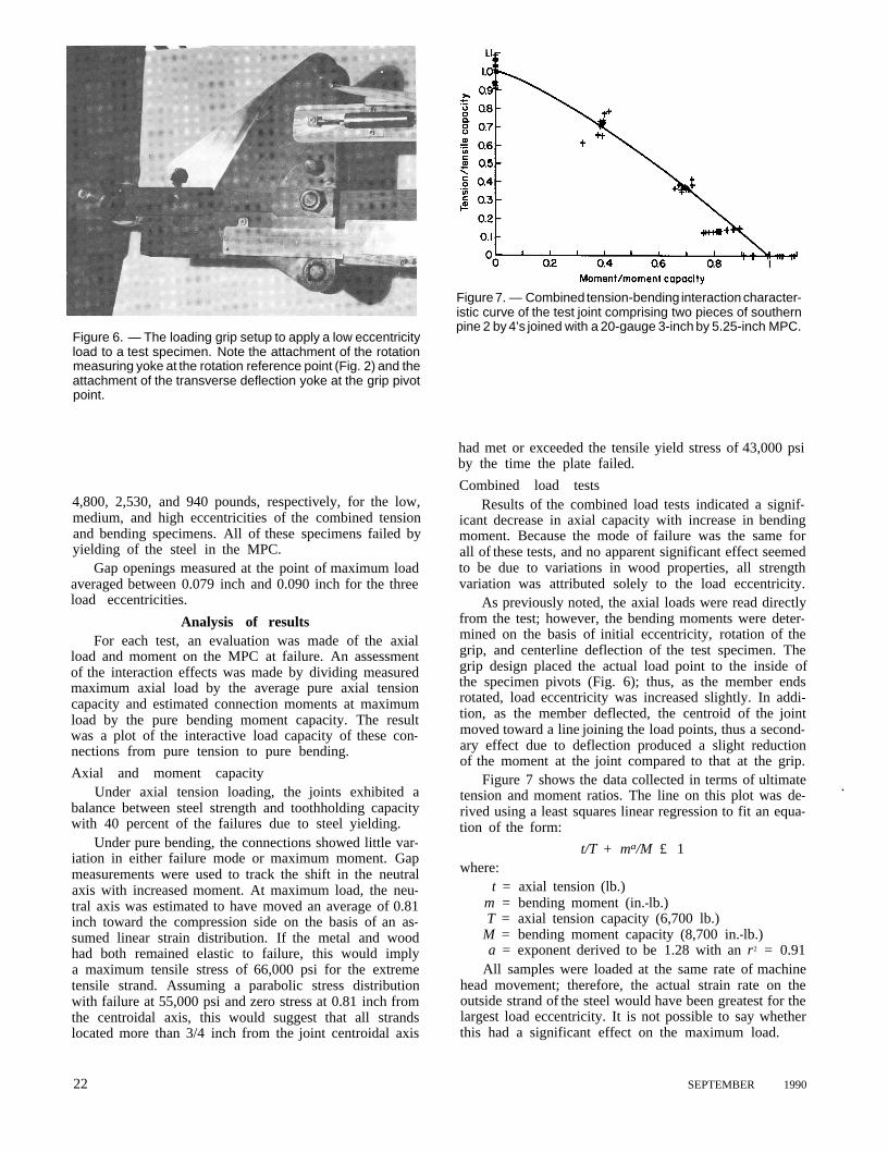
Figure 6. — The loading grip setup to apply a low eccentricity load to a test specimen. Note the attachment of the rotation measuring yoke at the rotation reference point (Fig. 2) and the attachment of the transverse deflection yoke at the grip pivot point.
4,800, 2,530, and 940 pounds, respectively, for the low, medium, and high eccentricities of the combined tension and bending specimens. All of these specimens failed by yielding of the steel in the MPC.
Gap openings measured at the point of maximum load averaged between 0.079 inch and 0.090 inch for the three load eccentricities.
Analysis of results For each test, an evaluation was made of the axial
load and moment on the MPC at failure. An assessment of the interaction effects was made by dividing measured maximum axial load by the average pure axial tension capacity and estimated connection moments at maximum load by the pure bending moment capacity. The result was a plot of the interactive load capacity of these con- nections from pure tension to pure bending. Axial and moment capacity
Under axial tension loading, the joints exhibited a balance between steel strength and toothholding capacity with 40 percent of the failures due to steel yielding.
Under pure bending, the connections showed little var- iation in either failure mode or maximum moment. Gap measurements were used to track the shift in the neutral axis with increased moment. At maximum load, the neu- tral axis was estimated to have moved an average of 0.81 inch toward the compression side on the basis of an as- sumed linear strain distribution. If the metal and wood had both remained elastic to failure, this would imply a maximum tensile stress of 66,000 psi for the extreme tensile strand. Assuming a parabolic stress distribution with failure at 55,000 psi and zero stress at 0.81 inch from the centroidal axis, this would suggest that all strands located more than 3/4 inch from the joint centroidal axis
Figure 7. — Combined tension-bending interaction character- istic curve of the test joint comprising two pieces of southern pine 2 by 4’s joined with a 20-gauge 3-inch by 5.25-inch MPC.
had met or exceeded the tensile yield stress of 43,000 psi by the time the plate failed. Combined load tests
Results of the combined load tests indicated a signif- icant decrease in axial capacity with increase in bending moment. Because the mode of failure was the same for all of these tests, and no apparent significant effect seemed to be due to variations in wood properties, all strength variation was attributed solely to the load eccentricity.
As previously noted, the axial loads were read directly from the test; however, the bending moments were deter- mined on the basis of initial eccentricity, rotation of the grip, and centerline deflection of the test specimen. The grip design placed the actual load point to the inside of the specimen pivots (Fig. 6); thus, as the member ends rotated, load eccentricity was increased slightly. In addi- tion, as the member deflected, the centroid of the joint moved toward a line joining the load points, thus a second- ary effect due to deflection produced a slight reduction of the moment at the joint compared to that at the grip.
Figure 7 shows the data collected in terms of ultimate tension and moment ratios. The line on this plot was de- rived using a least squares linear regression to fit an equa- tion of the form:
t/T + ma/M £ 1 where:
.
t = axial tension (lb.) m = bending moment (in.-lb.) T = axial tension capacity (6,700 lb.)
M = bending moment capacity (8,700 in.-lb.) a = exponent derived to be 1.28 with an r 2 = 0.91
All samples were loaded at the same rate of machine head movement; therefore, the actual strain rate on the outside strand of the steel would have been greatest for the largest load eccentricity. It is not possible to say whether this had a significant effect on the maximum load.
22 SEPTEMBER 1990

Conclusions Results of the tests show that the axial capacity of
the MPC tested is decreased significantly when a bend- ing moment is applied in conjunction with axial tension.
The significance of this study is not in the parameters for the interaction equation, but rather in the point that axial capacity is significantly affected by bending. MPCs subjected to combined bending and axial tension should be checked for their interactive load capacity, not just axial load capacity.
Literature cited
FOREST PRODUCTS JOURNAL Vol. 40, No. 9 23


![Behavior of bolted angle connections subjected to combined ...daryanpub.com/userfiles/file/Articles/sdarticle2.pdf · welded moment connections of steel frames [1,2]. Since then,](https://img.dokumen.tips/doc/110x75/5e9942a22ea80b5629071f77/behavior-of-bolted-angle-connections-subjected-to-combined-welded-moment-connections.jpg)


![Behaviour of combined channel/angle connections … of combined channel/angle connections to tubular columns under ... Eurocode 3 Part 1.8 [13] proposes rules ... performed tests on](https://img.dokumen.tips/doc/110x75/5aa9c7ab7f8b9a9a188d6241/behaviour-of-combined-channelangle-connections-of-combined-channelangle-connections.jpg)


