Embed Size (px)
Citation preview

Metal−Organic Framework Materials with Ultrahigh Surface Areas: Isthe Sky the Limit?Omar K. Farha,*,†,‡ Ibrahim Eryazici,†,‡ Nak Cheon Jeong,†,⊥ Brad G. Hauser,† Christopher E. Wilmer,§
Amy A. Sarjeant,† Randall Q. Snurr,§ SonBinh T. Nguyen,† A. Ozgur Yazaydın,*,∥ and Joseph T. Hupp*,†
†Department of Chemistry and International Institute for Nanotechnology, Northwestern University, 2145 Sheridan Road, Evanston,Illinois 60208-3113, United States§Department of Chemical & Biological Engineering, Northwestern University, 2145 Sheridan Road, Evanston, Illinois 60208, UnitedStates∥Department of Chemical Engineering, University of Surrey, Guildford, GU2 7XH, United Kingdom⊥Department of Emerging Materials Science, Daegu Gyeongbuk Institute of Science and Technology (DGIST), Daegu 711-873,Korea
*S Supporting Information
ABSTRACT: We have synthesized, characterized, and computation-ally simulated/validated the behavior of two new metal−organicframework (MOF) materials displaying the highest experimentalBrunauer−Emmett−Teller (BET) surface areas of any porousmaterials reported to date (∼7000 m2/g). Key to evacuating theinitially solvent-filled materials without pore collapse, and therebyaccessing the ultrahigh areas, is the use of a supercritical CO2activation technique. Additionally, we demonstrate computationallythat by shifting from phenyl groups to “space efficient” acetylenemoieties as linker expansion units, the hypothetical maximum surfacearea for a MOF material is substantially greater than previously envisioned (∼14600 m2/g (or greater) versus ∼10500 m2/g).
■ INTRODUCTION
Extensive research over the past few years has been focused onthe synthesis and characterization of microporous materialswith high internal surface areas. Metal−organic frameworks(MOFs),1−3 a crystalline subset of these materials, have shownpromise in a wide range of applications from gas storage,4−6
chemical separations,7−10 chemical sensing,11 and catalysis,12−14
to ion exchange,15 light harvesting,16,17 and drug delivery.18,19
High internal surface area is one of the foremost attributes ofMOFs and has been shown to be highly desirable in manypotential applications involving catalysis or storage. (Partic-ularly relevant is the sorption-based storage of technologicallyimportant gases at temperatures above their respective criticaltemperatures. For example, at T > 191 K methane cannot formmethane/methane multilayers; thermodynamically, excessadsorption, therefore, can be achieved only via direct contactbetween individual methane molecules and the sorbentsurface.)Additionally fueling interest in MOFs is their extraordinary
compositional and structural variety (e.g., ca. 10000 exper-imentally known MOFs versus fewer than 300 zeolites) and thefact that many display permanent porosity, ultralow densities,and well-defined pores and channels. Further, the crystallinityof MOFs allows for their unambiguous structural character-ization by X-ray diffraction, greatly simplifying efforts to usecomputational modeling to predict or explain their unusual or
unique physical properties. In this report, we have synthesizedand characterized two new MOFs that display the highestexperimental Brunauer−Emmett−Teller (BET) surface areas todate (∼7000 m2/g). Additionally, we demonstrate computa-tionally a new surface area ceiling for MOFs (∼14600 m2/g)that substantially exceeds what much of the MOF communityperceives to be a theoretical limit (∼10500 m2/g).One of the first breakthroughs in obtaining MOFs with
permanent microporosity came in 1998 from Li et al., whodescribed a material having a Langmuir surface area of 310 m2/g.20 Striking increases in reported surface areas for MOFsfollowed for the next several years, with values reaching 3800m2/g in 200521 and a remarkable 5200 m2/g in 2009.22 Amongthe reported high-area materials were MOF-523,24(especially inanhydrous form25), MOF-177,25,26 MIL-101,21 UMCM-1,27
and UMCM-222 (Table 1). Efforts to achieve even highersurface areas appeared to stall − not primarily because ofdifficulty in synthesizing new candidate materials, but becauseof the progressively greater tendency of these materials tocollapse upon removal of solvent. Fortunately, a MOFactivation method recently introduced by our lab28,29 andbased on supercritical carbon dioxide (see below) has enableddifficult-to-activate, large-cavity MOFs to be evacuated without
Received: June 8, 2012Published: August 20, 2012
Article
pubs.acs.org/JACS
© 2012 American Chemical Society 15016 dx.doi.org/10.1021/ja3055639 | J. Am. Chem. Soc. 2012, 134, 15016−15021

framework collapse or channel blockage. Based on this advance,two MOFs with experimentally accessible BET surface areasslightly above 6000 m2/g have been reported: MOF-21030 andNU-10031 (NU = Northwestern University; NU-100 is alsoknown as PCN-61032).
■ RESULTS AND DISCUSSIONMany researchers believe that the record-high surface areas forNU-10031 and MOF-21030 are “close to the ultimate[experimental] limit for solid materials.”33 This belief nodoubt stems from (a) simulations showing that the uppertheoretical limit for MOF surface areas is about 10500 cm2/gwhen linkers are constructed from repeating phenyl groups,25,34
and (b) anticipated practical problems, such as poor solubility,low synthetic yields, and cumbersome purification protocols,for candidate linkers featuring very large numbers of phenylrepeat units. We reasoned, however, that both the experimentalmaximum and the perceived theoretical ceiling could besubstantially increased by moving beyond phenyl-only strutsto more “area-efficient” acetylene building blocks for MOFlinkers. A recent preliminary report from our laboratoriesprovides qualitative support for this notion.35
We thus turned our attention to (3,24)-paddlewheelconnected MOF networks (rht-topology), pioneered by theEddaoudi group47 and significantly further explored by us,31,48
Zhou and co-workers32 and Schroeder and co-workers.41 A keyfeature of the rht-topology is that catenation (interpenetrationor interweaving of multiple frameworks) is mathematicallyprecluded.49,50 Capitalizing on this topology, we synthesizedtwo new materials with ultrahigh surface areas, NU-109 andNU-110, from two new hexa-carboxylated linkers. Thesynthesis and characterization of the hexa-carboxylic-acidforms of the desired linkers (LH6-1 and LH6-2, Figure 1aand h, Schemes S1 and S2) are described in the SupportingInformation (SI). Briefly, LH6 species were obtained via
saponification of the corresponding hexaester precursors,which, in turn, were obtained via Sonagashira coupling of
Table 1. BET Surface Areas and Pore Volumes for HighlyPorous MOFs
MOFBET surface area
(m2 g−1)pore volume(cm3 g−1) ref.
MFU-4 L 2750 1.26 36NOTT-102 2940 1.14 37PCN-61 3000 1.36 38Cu24(TPBTM)8(H2O)24 3160 1.27 39SNU-77 3670 1.52 40NOTT-112 3800 1.62 41MOF-5 3800 1.55 24UMCM-1-NH2 3920 42PCN-66 4000 1.36 38Be12(OH)12(BTB)24 4030 43UMCM-1 4160 27MIL-101c 4230 2.15 21Bio-MOF-100 4300 4.30 44MOF-205 4460 2.16 30MOF-177 4750 1.59 26DUT-23-Co 4850 2.03 45NOTT-116/PCN-68 4660/5110 2.17 32, 46UMCM-2 5200 2.32 22NU-100 6140 2.82 31MOF-210 6240 3.6 30NU-109E 7010 3.75 HereinNU-110E 7140 4.40 Herein
Figure 1. Structural features of NU-109 and NU-110. (a) Schematicdrawing of the chemical structure of LH6 for NU-109. (b−g)Representations of the single-crystal X-ray structure of NU-109showing: LH6 connecting six paddlewheel units (b), cubaoctahedralbuilding blocks (c), and different cages within NU-109 (d−g). (h)Schematic drawing of the chemical structure of LH6 for NU-110. (i−n) Representations of the single-crystal X-ray structure of NU-110showing: LH6 connecting six paddlewheel units (i), cubaoctahedralbuilding blocks (j), and different cages in NU-110 (k−n). Hydrogensand disordered solvent molecules are omitted for clarity. Carbon =gray; oxygen = red; copper = teal. Purple spheres are included to guidethe eye in distinguishing between the three cages.
Journal of the American Chemical Society Article
dx.doi.org/10.1021/ja3055639 | J. Am. Chem. Soc. 2012, 134, 15016−1502115017

1,3,5-triiodobenzene with the appropriate acetylene-terminatedcompounds.Solvothermal reactions of LH6-1 or LH6-2 and Cu-
(NO3)2·2.5H2O in DMF/EtOH/HCl (DMF = dimethylforma-mide) at 75 °C afforded MOFs having the framework formula[Cu3(L
6−(109))(H2O)3]n (NU-109E, E = Experimental, L6−
(109)= the hexa-anion of LH6-1) or [Cu3(L
6−(110))(H2O)3]n (NU-
110E, L6−(110) = the hexa-anion of LH6-2) after 48 h. X-ray
analysis of single crystals of NU-109E and NU-110E revealednoncatenated structures in which the framework nodes consistof CuII2 units coordinated by the carboxylates of L6− in apaddlewheel fashion. The axial sites of the CuII2 units arecoordinated by water molecules that were not well resolved inthe X-ray analysis (Figures 1b and i). The experimentalstructures of NU-109E and NU-110E were found to be inexcellent agreement with the predicted structures, NU-109SP(SP = Simulation of the Predicted structure) and NU-110SP(see SI for more details). The predicted and experimentalstructures of both materials have a cubic space group, Fm3 m,with unit-cell dimensions of a = b = c = 65.899 Å (NU-109SPat 0 K), 64.528 Å (NU-109E at 100 K), 70.330 Å (NU-110SPat 0 K), and 68.706 Å (NU-110E at 297 K). The differences inthe unit cells between the experimental and simulatedstructures are only 1.37 and 1.62 Å for NU-109 and NU-110, respectively. The experimental structures were solved, inpart, by utilizing the coordinates of the in silico structurespredicted by using molecular modeling techniques.NU-109 and NU-110 share several topological features.
Briefly, each L6− unit contributes to the formation of threecuboctahedron cages (Figures 1c and j). Both contain threetypes of cages (Figures 1g and n, Figure S19) that are fused inways that provide for continuous channels. Cuboctahedral cage1 (Figures 1d and k) is formed from 24 isophthalate groupsfrom L6− units and 12 pairs of copper ions (i.e., 24 total). Thenodes forming triangular windows in cage 1 are shared withcage 2 (Figures 1e and l), while those forming rectangularwindows are shared with cage 3 (Figures 1f and m). Cage 2(Figures 1e and l) defines a truncated tetrahedron, and is
formed from isophthalate groups from four L6− linkers and 12pairs of copper ions (i.e., 24 total). As expected, cage 3 (Figure1f and m) is describable as a truncated cuboctahedron and isformed by 24 Cu2
II paddlewheel nodes and portions of eightdistinct L6− units.The phase purity of bulk samples of NU-109 and NU-110
was confirmed via powder X-ray diffraction (PXRD) measure-ments (Figures 2a and b). Additionally, the simulated PXRDpatterns from experimental and predicted structures are inexcellent agreement (Figure 2c). This confirms that, apart fromminor differences in unit cell dimensions, the predictedstructures are identical to the experimentally obtained materials.These differences are tentatively ascribed to the differencebetween experimental (i.e., X-ray collection) and simulationtemperatures. Furthermore, we compared the PXRD patternsof NU-109SE (SE = simulated from experimental structure)and NU-110SE to NU-100SE31 and NOTT-11646/PCN-68,32
which likewise share the rht-topology. These patterns (Figures2d and e) show the lowest angle peak progressively shifting tosmaller 2θ, which corresponds to an increasing unit cell lengthand therefore a larger distance between the copper nodes,culminating with NU-110SE. Thermogravimetric analysis(TGA) of NU-109E and NU-110E revealed in both cases amass loss at about 100 °C, assigned to solvent (DMF), with nofurther mass loss occurring until 325 °C (Figure 2f). BothMOFs contain more free solvent than either NU-100E/PCN-610 or NOTT-116E/PCN-68E, pointing to the potential forgreater permanent porosity.Regardless of how striking the NU-109E and NU-110E
structures may be, for many applications−especially thosecentering on storage and separation−removal of guest solventmolecules from the pores without significantly diminishingporosity is crucial. Failure to prevent porosity loss will result insignificant discrepancies between the surface areas obtainedexperimentally and those estimated from computationalmodeling. Since MOFs containing large pores such as NU-109 and NU-110 are particularly predisposed to collapse, weemployed an unconventional MOF activation strategy recently
Figure 2. TGA and PXRD profiles. (a−c) PXRD patterns of NU-109 and NU-110. (d−e) PXRD patterns of NU-109, NU-110, NU-100,31 andNOTT-11646/PCN-68.32 (f) TGA profiles of NU-109, NU-110, NU-100,31 and NOTT-11646/PCN-68.32
Journal of the American Chemical Society Article
dx.doi.org/10.1021/ja3055639 | J. Am. Chem. Soc. 2012, 134, 15016−1502115018

developed by our team28,29 and now used by MOF researchersthroughout the world (e.g., Kaskel,45 Yaghi,30,51 Hong52 andothers) to activate them. The activation takes advantage ofsupercritical carbon dioxide (SCD) processing, which wasperformed with a Tousimis Samdri PVT-30 critical point dryer.Prior to drying, DMF/EtOH-solvated MOF samples weresoaked in 100% ethanol, replacing the soaking solution everyday for 3 days. The ethanol-containing samples were placedinside the dryer and the ethanol was exchanged with CO2 (liq.)over a period of 10 h. The temperature was then raised andCO2 was vented under supercritical conditions where capillaryforces and solvent surface-tension are inherently absent (see SIfor more details).The porosities of SCD-activated NU-109 and NU-110 were
examined via nitrogen adsorption at 77 K. N2 isothermsshowed extraordinarily high limiting uptakes of 2480 and 2845cm3/g for NU-109E and NU-110E, respectively (Figure 3).
The experimental BET surface areas of activated NU-109E andNU-110E were found to be 7010 and 7140 m2/g, in excellentagreement with the fitted (in silico) BET surface areas for NU-109SE (6950 m2/g) and NU-110SE (7400 m2/g) and with thesimulated BET surface area for NU-109SP (7560 m2/g) andNU-110SP (7800 m2/g) (Table 2). The deviation in surfaceareas between the SE and SP materials reflect the small, butfinite, differences in dimensions of the experimental versuscalculated unit cells. Nonetheless, these surface areas are thehighest for any porous materials reported to date. Moreover,the total pore volumes of NU-109E and NU-110E are 3.75 and4.40 cm3/g, which are substantially larger than any other high-
pore-volume MOFs (see Table 1). Finally, the observed voidvolumes of ca. 93% (for each) exceed those for any othersolvent-evacuated MOF material described to date. It is worthnoting that the nitrogen isotherms shown in Figure 3 are type-IV rather than type-I, reflecting the fact that both NU-109 andNU-110 contain multiple types (sizes) of pores. The simulatedisotherms show three distinct regions, while the experimentaldata do not resolve these as clearly. However, the simulated andexperimental pore size distributions are in excellent agreementas shown in Figures S30 and S32 (SI). Additionally, PXRDpatterns for as-synthesized, activated, and resolvated NU-109and NU-100 show no evidence for structural changes duringactivation and porosity measurements (Figures S34 and S35).While the BET surface areas of the new MOFs are large
(nearly 70% of the theoretical maximum for materials withbenzene-derived linkers), can higher surface area materials beexperimentally obtained? Attempts have been made previouslyto calculate the highest possible surface area for a porousmaterial. Chae at al.25 described a useful conceptual basis for astrategy to achieve high-surface-area ordered materials. Byprogressively excising smaller fragments from an infinitegraphene sheet and calculating Connolly53 surface areas ofthe remaining framework, they found that exposing all latentedges to give isolated six-membered rings would yield a surfacearea of 7745 m2/g. The exposed six-membered rings wereessentially benzene molecules without hydrogens, whoseinclusion would have given an even higher surface area. Byputting this strategy into practice, they synthesized MOF-177from Zn4O clusters and 1,3,5-benzenetribenzoate (BTB)organic linkers, which showed a record-breaking surface areaat that time (4750 cm2/g). (Subsequently, it was realized thatfor sorption applications, molecule-accessible surface areas arephysically more meaningful than Connolly surface areas.54
Additionally, Snurr and co-workers showed that, subject towell-defined “consistency criteria”, experimental BET surfaceareas for fully evacuated MOFs (but not Langmuir or Connollysurface areas) correspond closely to molecule-accessible surfaceareas.54)In a related approach, Schnobrich et al.34 constructed a series
of structures (in silico) by incrementally adding benzenes to thelinker of MOF-5 (1,4-terephthalic acid). This study revealedthat a MOF-5 analogue with an infinite number of benzenes inits linker would give an N2-accessible surface area of 10436 m
2/g, which is very close to the maximum attainable surface area(10577 m2/g) for structures derived from benzene ringsregardless of their topology. These studies have, until now,largely defined surface-area targets for MOF materials for bothexperimental and theoretical investigations, and the use ofbenzene chains of different forms and lengths has become acommon way of synthesizing materials with high surface areas.Here we propose and demonstrate that there are routes to
attaining MOFs with even higher surface areas. The basis ofone of these routes relies on further exposing the edges of a six-membered carbon ring by dividing it into three separate butchemically linked pieces, where each consists of two carbonatoms linked by a triple bond. These pieces are roughlyequivalent to acetylenes, but with carbon−carbon single bondsto neighboring pieces replacing terminal hydrogen atoms.Employing three linked acetylenes in place of a single benzenering in a material should result in a significantly highermolecule-accessible surface area, since larger numbers ofexposed edges (i.e., adsorption sites) are presented.54 Wehypothesized that stepwise addition of acetylenes to the linker
Figure 3. Sorption data for NU-109E and NU-110E. Experimentalnitrogen isotherms for NU-109E (red squares) and NU-110E (bluecircles).
Table 2. Experimental and Simulated Surface Areas and PoreVolumes for NU-109, NU-110, NU-109SP, and NU-110SPa
MOF BET surface area (m2 g−1) pore volume (cm3 g−1)
NU-109SP 7560 4.12NU-109SE 6950 3.90NU-109E 7010 ± 80 3.75NU-110SP 7800 4.44NU-110SE 7400 4.18NU-110E 7140 4.40
aSP = simulated from predicted structure; SE = simulated fromexperimental structure; E = experimental results.
Journal of the American Chemical Society Article
dx.doi.org/10.1021/ja3055639 | J. Am. Chem. Soc. 2012, 134, 15016−1502115019
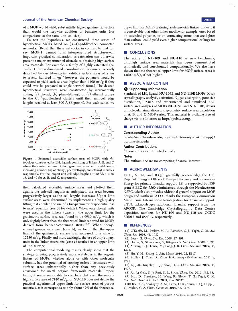
of a MOF would yield, substantially higher gravimetric surfacethan would the stepwise addition of benzene units (forcomparisons at the same unit cell size).To test the hypothesis, we constructed three series of
hypothetical MOFs based on (3,24)-paddlewheel connectednetworks. (Recall that these networks, in contrast to that for,say, MOF-5, cannot form interpenetrated structures−animportant practical consideration, as catenation can otherwisepresent a major experimental obstacle to obtaining high surfacearea materials. For example, a family of highly catenated (ca.12-fold) terpyridine-based coordination polymers recentlydescribed by our laboratories, exhibits surface areas of a fewto several hundred m2/g;55 however, the polymers would beexpected to yield surface areas higher than 6400 m2/g if theycould ever be prepared in single-network form.) The desiredhypothetical structures were constructed by incrementallyadding (a) phenyl, (b) phenylethynyl, or (c) ethynyl groupsto the Cu2
II-paddlewheel clusters until their unit-cell edgelengths reached at least 300 Å (Figure 4). For each series, we
then calculated accessible surface areas and plotted themagainst the unit-cell lengths; as anticipated, the areas becomeprogressively larger as the cell lengths increases. Upper limitsurface areas were determined by implementing a high-qualityfitting that entailed the use of a five-parameter “exponential riseto max” equation (see SI for details). When only phenyl unitswere used in the linkers (case a), the upper limit for thegravimetric surface area was found to be 9950 m2/g, which isonly slightly lower than the theoretical limit reported for MOFsderived from benzene-containing struts.25,34 When phenyl-ethynyl groups were used (case b), we found that the upperlimit of the gravimetric surface area increased to a value of12250 m2/g. Finally and most excitingly, the use of only ethynylunits in the linker extensions (case c) resulted in an upper limitof 14600 m2/g.The computational modeling results clearly show that the
strategy of using progressively more acetylenes in the organiclinkers of MOFs, whether alone or with other molecularsubunits, has the potential of creating ordered structures withsurface areas substantially higher than any previouslyenvisioned for metal−organic framework materials. Impor-tantly, it seems reasonable to conclude that even the record-high surface area of 7140 m2/g for NU-110 does not define thepractical experimental upper limit for surface areas of porousmaterials, as it corresponds to only about 49% of the theoretical
upper limit for MOFs featuring acetylene-rich linkers. Indeed, itis conceivable that other linker motifs−for example, ones basedon extended polyenes, or on connecting-atoms that are lighterthan carbon−could yield even higher computational ceilings forsurface areas.
■ CONCLUSIONSThe utility of NU-109 and NU-110 as new benchmark,ultrahigh surface area materials has been demonstratedsynthetically and corroborated computationally. We also haveshown that the theoretical upper limit for MOF surface areas is14600 m2/g, if not higher.
■ ASSOCIATED CONTENT*S Supporting InformationSynthesis of LH6 ligand, NU-109E and NU-110E MOFs; X-raycrystallography analysis, activation, N2 gas adsorption, pore sizedistribution, PXRD, and experimental and simulated BETsurface area analyses of MOFs NU-109E and NU-110E; detailsof molecular simulations and geometric surface area calculationof A, B, and C MOF series. This material is available free ofcharge via the Internet at http://pubs.acs.org.
■ AUTHOR INFORMATIONCorresponding [email protected]; [email protected]; [email protected]
Author Contributions‡These authors contributed equally.
NotesThe authors declare no competing financial interest.
■ ACKNOWLEDGMENTSJ.T.H., S.T.N., and R.Q.S. gratefully acknowledge the U.S.Dept. of Energy’s Office of Energy Efficiency and RenewableEnergy for primary financial support. I.E. is supported by NSFgrant # EEC-0647560 administered through the NorthwesternNSEC, which also provides additional general support on MOFdesign and synthesis. A.O.Y. thanks the European CommissionMarie Curie International Reintegration for financial support.S.T.N. acknowledges additional financial support from theAFOSR. The Cambridge Crystallographic Data Centredeposition numbers for NU-109 and NU-110 are CCDC856012 and 856013, respectively.
■ REFERENCES(1) O’Keeffe, M.; Peskov, M. A.; Ramsden, S. J.; Yaghi, O. M. Acc.Chem. Res. 2008, 41, 1782.(2) Ferey, G. Chem. Soc. Rev. 2008, 37, 191.(3) Horike, S.; Shimomura, S.; Kitagawa, S. Nat. Chem. 2009, 1, 695.(4) Murray, L. J.; Dinca, M.; Long, J. R. Chem. Soc. Rev. 2009, 38,1294.(5) Hu, Y. H.; Zhang, L. Adv. Mater. 2010, 22, E117.(6) Sculley, J.; Yuan, D.; Zhou, H.-C. Energy Environ. Sci. 2011, 4,2721.(7) Li, J.-R.; Kuppler, R. J.; Zhou, H.-C. Chem. Soc. Rev. 2009, 38,1477.(8) An, J.; Geib, S. J.; Rosi, N. L. J. Am. Chem. Soc. 2010, 132, 38.(9) Britt, D.; Furukawa, H.; Wang, B.; Glover, T. G.; Yaghi, O. M.Proc. Natl. Acad. Sci. U.S.A. 2009, 106, 20637.(10) Bae, Y.-S.; Spokoyny, A. M.; Farha, O. K.; Snurr, R. Q.; Hupp, J.T.; Mirkin, C. A. Chem. Commun. 2010, 46, 3478.
Figure 4. Estimated accessible surface areas of MOFs with rht-topology constructed by LH6 ligands consisting of linkers A, B, and C,where the center benzene of the ligand was extended by addition ofincreasing number (n) of phenyl, phenylethynyl, and ethynyl moieties,respectively. For the longest unit cell edge lengths (∼310 Å), n is 26,15, and 40 for A, B, and C, respectively.
Journal of the American Chemical Society Article
dx.doi.org/10.1021/ja3055639 | J. Am. Chem. Soc. 2012, 134, 15016−1502115020

(11) Allendorf, M. D.; Bauer, C. A.; Bhakta, R. K.; Houk, R. J. T.Chem. Soc. Rev. 2009, 38, 1330.(12) Ma, L.; Abney, C.; Lin, W. Chem. Soc. Rev. 2009, 38, 1248.(13) Lee, J.; Farha, O. K.; Roberts, J.; Scheidt, K. A.; Nguyen, S. T.;Hupp, J. T. Chem. Soc. Rev. 2009, 38, 1450.(14) Farha, O. K.; Shultz, A. M.; Sarjeant, A. A.; Nguyen, S. T.;Hupp, J. T. J. Am. Chem. Soc. 2011, 133, 5652.(15) An, J.; Rosi, N. L. J. Am. Chem. Soc. 2010, 132, 5578.(16) Lee, C. Y.; Farha, O. K.; Hong, B. J.; Sarjeant, A. A.; Nguyen, S.T.; Hupp, J. T. J. Am. Chem. Soc. 2011, 133, 15858.(17) Kent, C. A.; Mehl, B. P.; Ma, L.; Papanikolas, J. M.; Meyer, T. J.;Lin, W. J. Am. Chem. Soc. 2010, 132, 12767.(18) Horcajada, P.; Serre, C.; Vallet-Regí, M.; Sebban, M.; Taulelle,F.; Ferey, G. Angew. Chem., Int. Ed. 2006, 45, 5974.(19) Rocca, J. D.; Liu, D.; Lin, W. Acc. Chem. Res. 2011, 44, 957.(20) Li, H.; Eddaoudi, M.; Groy, T. L.; Yaghi, O. M. J. Am. Chem. Soc.1998, 120, 8571.(21) Ferey, G.; Mellot-Draznieks, C.; Serre, C.; Millange, F.; Dutour,J.; Surble, S.; Margiolaki, I. Science 2005, 309, 2040.(22) Koh, K.; Wong-Foy, A. G.; Matzger, A. J. J. Am. Chem. Soc.2009, 131, 4184.(23) Li, H.; Eddaoudi, M.; O’Keeffe, M.; Yaghi, O. M. Nature 1999,402, 276.(24) Kaye, S. S.; Dailly, A.; Yaghi, O. M.; Long, J. R. J. Am. Chem. Soc.2007, 129, 14176.(25) Chae, H. K.; Siberio-Perez, D. Y.; Kim, J.; Go, Y.; Eddaoudi, M.;Matzger, A. J.; O’Keeffe, M.; Yaghi, O. M. Nature 2004, 427, 523.(26) Furukawa, H.; Miller, M. A.; Yaghi, O. M. J. Mater. Chem. 2007,17, 3197.(27) Koh, K.; Wong-Foy, A. G.; Matzger, A. J. Angew. Chem., Int. Ed.2008, 47, 677.(28) Nelson, A. P.; Farha, O. K.; Mulfort, K. L.; Hupp, J. T. J. Am.Chem. Soc. 2008, 131, 458.(29) Farha, O. K.; Hupp, J. T. Acc. Chem. Res. 2010, 43, 1166.(30) Furukawa, H.; Ko, N.; Go, Y. B.; Aratani, N.; Choi, S. B.; Choi,E.; Yazaydın, A. O.; Snurr, R. Q.; O’Keeffe, M.; Kim, J.; Yaghi, O. M.Science 2010, 329, 424.(31) Farha, O. K.; Yazaydın, A. O.; Eryazici, I.; Malliakas, C. D.;Hauser, B. G.; Kanatzidis, M. G.; Nguyen, S. T.; Snurr, R. Q.; Hupp, J.T. Nat. Chem. 2010, 2, 944.(32) Yuan, D.; Zhao, D.; Sun, D.; Zhou, H.-C. Angew. Chem., Int. Ed.2010, 49, 5357.(33) Liu, J.; Thallapally, P. K.; McGrail, B. P.; Brown, D. R.; Liu, J.Chem. Soc. Rev. 2012.(34) Schnobrich, J. K.; Koh, K.; Sura, K. N.; Matzger, A. J. Langmuir2010, 26, 5808.(35) Farha, O. K.; Wilmer, C. E.; Eryazici, I.; Hauser, B. G.; Parilla, P.A.; O’Neill, K.; Sarjeant, A. A.; Nguyen, S. T.; Snurr, R. Q.; Hupp, J. T.J. Am. Chem. Soc. 2012, 134, 9860.(36) Denysenko, D.; Grzywa, M.; Tonigold, M.; Streppel, B.; Krkljus,I.; Hirscher, M.; Mugnaioli, E.; Kolb, U.; Hanss, J.; Volkmer, D.Chem.Eur. J. 2011, 17, 1837.(37) Lin, X.; Telepeni, I.; Blake, A. J.; Dailly, A.; Brown, C. M.;Simmons, J. M.; Zoppi, M.; Walker, G. S.; Thomas, K. M.; Mays, T. J.;Hubberstey, P.; Champness, N. R.; Schroder, M. J. Am. Chem. Soc.2009, 131, 2159.(38) Zhao, D.; Yuan, D.; Sun, D.; Zhou, H.-C. J. Am. Chem. Soc.2009, 131, 9186.(39) Zheng, B.; Bai, J.; Duan, J.; Wojtas, L.; Zaworotko, M. J. J. Am.Chem. Soc. 2011, 133, 748.(40) Park, H. J.; Lim, D.-W.; Yang, W. S.; Oh, T.-R.; Suh, M. P.Chem.Eur. J. 2011, 17, 7251.(41) Yan, Y.; Lin, X.; Yang, S.; Blake, A. J.; Dailly, A.; Champness, N.R.; Hubberstey, P.; Schroder, M. Chem. Commun. 2009, 1025.(42) Wang, Z.; Tanabe, K. K.; Cohen, S. M. Chem.Eur. J. 2010, 16,212.(43) Sumida, K.; Hill, M. R.; Horike, S.; Dailly, A.; Long, J. R. J. Am.Chem. Soc. 2009, 131, 15120.
(44) An, J.; Farha, O. K.; Hupp, J. T.; Pohl, E.; Yeh, J. I.; Rosi, N. L.Nat. Commun. 2012, 3, 604.(45) Klein, N.; Senkovska, I.; Baburin, I. A.; Grunker, R.; Stoeck, U.;Schlichtenmayer, M.; Streppel, B.; Mueller, U.; Leoni, S.; Hirscher, M.;Kaskel, S. Chem.Eur. J. 2011, 17, 13007.(46) Yan, Y.; Telepeni, I.; Yang, S.; Lin, X.; Kockelmann, W.; Dailly,A.; Blake, A. J.; Lewis, W.; Walker, G. S.; Allan, D. R.; Barnett, S. A.;Champness, N. R.; Schroder, M. J. Am. Chem. Soc. 2010, 132, 4092.(47) Nouar, F.; Eubank, J. F.; Bousquet, T.; Wojtas, L.; Zaworotko,M. J.; Eddaoudi, M. J. Am. Chem. Soc. 2008, 130, 1833.(48) Eryazici, I.; Farha, O. K.; Hauser, B. G.; Yazaydın, A. O.;Sarjeant, A. A.; Nguyen, S. T.; Hupp, J. T. Cryst. Growth Des. 2012, 12,1075.(49) Delgado-Friedrichs, O.; O’Keeffe, M. Acta Crystallogr., Sect. A2007, 63, 344.(50) Reticular Chemistry Structure Resource (RCSR) website,http://rcsr.anu.edu.au/.(51) Valente, C.; Choi, E.; Belowich, M. E.; Doonan, C. J.; Li, Q.;Gasa, T. B.; Botros, Y. Y.; Yaghi, O. M.; Stoddart, J. F. Chem. Commun.2010, 46, 4911.(52) Han, D.; Jiang, F.-L.; Wu, M.-Y.; Chen, L.; Chen, Q.-H.; Hong,M.-C. Chem. Commun. 2011, 47, 9861.(53) Connolly, M. L. Science 1983, 221, 709.(54) Duren, T.; Millange, F.; Ferey, G.; Walton, K. S.; Snurr, R. Q. J.Phys. Chem. C 2007, 111, 15350.(55) Eryazici, I.; Farha, O. K.; Compton, O. C.; Stern, C.; Hupp, J.T.; Nguyen, S. T. Dalton Trans. 2011, 40, 9189.
Journal of the American Chemical Society Article
dx.doi.org/10.1021/ja3055639 | J. Am. Chem. Soc. 2012, 134, 15016−1502115021