Embed Size (px)
Citation preview

MCRMA Technical Paper No 11 DECEMBER 2006 REVISED EDITION
_______________________________________ METAL FABRICATIONS: DESIGN, DETAILING AND INSTALLATION GUIDE _______________________________________ THIS DOCUMENT IS NO LONGER IN PRINT AND IS INCLUDED ON THE WEB SITE FOR REFERENCE ONLY PLEASE REFER TO AN MCRMA MEMBER FOR UP TO DATE INFORMATION THE METAL CLADDING & ROOFING MANUFACTURERS ASSOCIATION

Contents
Page
1.0 Introduction 1
2.0 Glossary of terms 1
3.0 Design and specification 3
3.1 Laps/junctions 3
3.2 Fasteners 5
3.3 Sealants 6
3.4 Insulation and vapour control layer 6
3.5 Materials 6
4.0 Architectural details 8
4.1 Introduction 8
4.2 Mitred flat panels 8
4.3 Mitred profile corners 9
4.4 Bull noses 9
4.5 Bull nose corners 9
4.6 Wings, fins and aerofoils 9
4.7 Window surrounds 9
4.8 Louvre systems 10
4.9 Curved fabrications 10
4.10 Fascia and soffit systems 10
5.0 Manufacture 12
6.0 Special requirements for aluminium 13
6.1 Allowance for expansion 13
6.2 Design and installation 13
6.3 Sealants 14
6.4 Welding 14
6.5 Fasteners 14
6.6 Aesthetics 15
7.0 Penetrations 15
7.1 Rubber gaskets 15
7.2 Profiled soakers 15
7.3 Apron fabrications 16
7.4 On-site weldings 16
7.5 On-site GRP 16
7.6 General 16
8.0 Workmanship 17
8.1 Good housekeeping 17
8.2 Tools 17
8.3 Fasteners 18
8.4 Site measurement and setting out 18
9.0 Problem-solving 19
For up to date information on metal roof and wall cladding, including
downloadable construction details in 3D, visit www.mcrma.co.uk. © The Metal Cladding & Roofing Manufacturers Association Limited. December 2006
1.0 Introduction 2.0 Glossary of terms
The purpose of this design guide is to establish
the basic principles behind the successful
design, detailing and installation of fabrications
in profiled metal roofs and walls.
Much attention is paid in design to the metal roof
or wall construction and the basic shape of
fabrications however; the vital junctions and fixings
etc and the appearance of fabrications can be
overlooked and are often left to the experience of the
fixer on site. In fact, on many buildings it is the
fabrications that the user of the building will notice
first, particularly on curved roofs. Complaints to
roofing contractors and manufacturers concerning
leakage are mainly due to fabrications, either in
design or indifferent workmanship.
This guide addresses aspects of steel and
aluminium fabrications and workmanship, together
with special applications such as GRP soakers or
on-site welding. It does not deal with the shape of
a fabrication to suit a particular junction but with
the jointing and use of the fabrication itself. While
aluminium fabrications are referred to throughout
the guide, the particular requirements for
aluminium are discussed in section 6.0.
As with any engineering problem there is always
more than one solution to a fabrication design
and a multitude of opinions about the correct
methods. MCRMA has endeavoured to present
the optimum solutions and the best practice from
a wide variety of sources and where there are
choices, the merits of each one is discussed.
Note: The following descriptions only apply in the
context of metal roofing and cladding
Apron fabrication A wide flat fabrication used to
weather from the back of an opening back to a
ridge or other interruption in the roof. An apron
fabrication is at the same level as the top or
crown of the roofing profile.
Bird mouth The gaping of a lap joint.
Butt strap Used to join two fabrications which butt
together, usually closure fabrications.
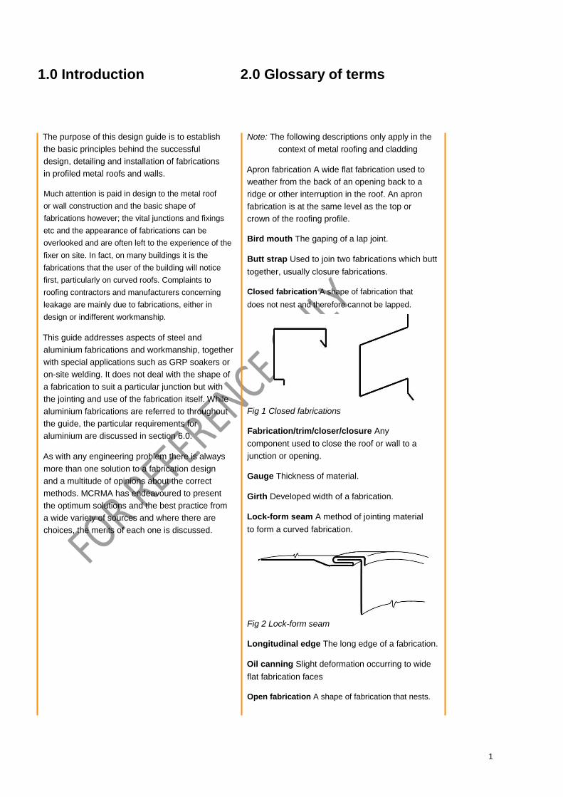
Closed fabrication A shape of fabrication that
does not nest and therefore cannot be lapped.
Fig 1 Closed fabrications
Fabrication/trim/closer/closure Any
component used to close the roof or wall to a
junction or opening.
Gauge Thickness of material.
Girth Developed width of a fabrication.
Lock-form seam A method of jointing material
to form a curved fabrication.
Fig 2 Lock-form seam
Longitudinal edge The long edge of a fabrication.
Oil canning Slight deformation occurring to wide
flat fabrication faces
Open fabrication A shape of fabrication that nests.
1
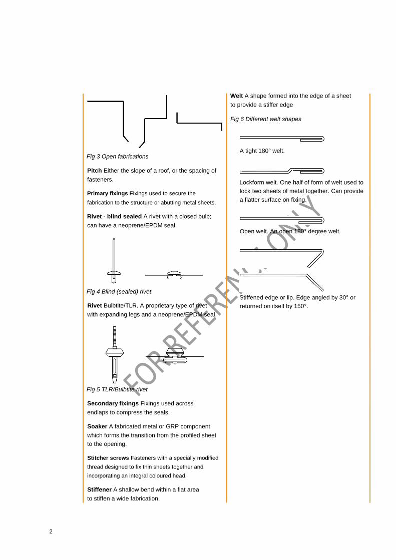
Fig 3 Open fabrications
Pitch Either the slope of a roof, or the spacing of fasteners.
Primary fixings Fixings used to secure the
fabrication to the structure or abutting metal sheets.
Rivet - blind sealed A rivet with a closed bulb;
can have a neoprene/EPDM seal.
Fig 4 Blind (sealed) rivet
Rivet Bulbtite/TLR. A proprietary type of rivet
with expanding legs and a neoprene/EPDM seal.
Fig 5 TLR/Bulbtite rivet
Secondary fixings Fixings used across
endlaps to compress the seals.
Soaker A fabricated metal or GRP component
which forms the transition from the profiled sheet
to the opening.
Stitcher screws Fasteners with a specially modified
thread designed to fix thin sheets together and
incorporating an integral coloured head.
Stiffener A shallow bend within a flat area
to stiffen a wide fabrication.
Welt A shape formed into the edge of a sheet
to provide a stiffer edge
Fig 6 Different welt shapes
A tight 180° welt.
Lockform welt. One half of form of welt used to
lock two sheets of metal together. Can provide
a flatter surface on fixing.
Open welt. An open 180° degree welt.
Stiffened edge or lip. Edge angled by 30° or
returned on itself by 150°.
2

3.0 Design and Specification
3.1 Laps/junctions Lap joints form the simplest joint in open shape
flashings. Lap joints in closed shape fabrications
that do not nest easily can ‘bird mouth’. In these
cases, butt straps of 150mm minimum designed
to fit within the fabrication are needed. To
enable a flashing to lap well, any welt or lip
should be trimmed off the length of the lap. Lap
joints on sloping flashings for example, verges
should be formed to overlap the downslope.
The width of a fabrication should be kept to the
minimum that can be achieved practically to reduce
the vulnerability to foot traffic and end laps opening.
There are conditions where fabrications can be
open jointed provided that they are not
required to perform a weathering function.
Examples are features or bullnoses installed
either outside the building line or over
previously weathered components.
Fabrications required to provide weathering
should have a double run of sealant applied either
side of the line of fasteners or a wide channel
shaped seal through which the fastener can be
installed. This must be used with care to prevent
winding of the sealant around the fastener.
Butt straps should be designed and fabricated
to take into account sealant thicknesses.
Low modulus (neutral cure) silicone sealants
can be over compressed within joints when
fasteners are installed which results in a seal
that will not perform in the long term when
movement occurs. If such sealants are to be
employed, spacers should be used to ensure
that a minimum gap of approximately 6m is
achieved. Preferably, these joints should be
sealed using an NFRC Class A butyl strip seal.
Generally large unsupported flat areas over
200mm wide should be avoided if possible unless
stiffening folds can be introduced.
Where the appearance of fabrications is important,
factory-fabricated corners and junctions should be
used. It is also prudent that aesthetically sensitive
items should be subject to the architect’s approval
of a sample prior to volume manufacture and that the
sample be retained on site for future reference. If at
all possible the sample should be installed in the
building, including a joint, and offered to the design
team for comment or approval.
100-150mm
butt strap
Single sealant strips
75-100mm
between fixings
Fig 7 Closed steel fabrication: butt joint, single
lines of sealant
Secondary
fixing
Primary fixing
150 mm
Sealant
450mm between
primary fixings
Fig 8 Open steel fabrication: lap joint, single
sealant strip (steel)
Sealant Fixing at each
end of arc
Curved aluminium
bullnose
Factory welded butt strap
Fig 9 Welded butt strap on aluminium bullnose – show twin seals
3

Primary fixing
450mm Single sealant strip
75-100mm
150mm (roof) 100mm (wall)
Lip removed for Primary fixing
at max. 450mm c/c length of lap
Fig 10 Open steel fabrication: lap joint single line
of sealant – show twin seals
Summary
• Minimum lap 150mm on roofs, 100mm
on walls
• Only open fabrications that nest
should be lapped; use butt straps with
closed fabrications
• Minimum butt strap length 150mm • Butt straps should fit within the fabrication
profile with an allowance for sealant thickness
• Stitch laps at 75-100mm centres • Position the first line of sealant on
the weatherside of the joint
Stop fascia fabrication butt straps at the lower
shadow line to prevent water tracking around the
gap at the butt strap onto the wall. Pointing the
gap at a butt strap with clear silicone for example,
is not recommended because the silicone can
pick up dirt and any smears soon become dirty.
Butt strap behind
joint, no mastic in gap
Step joint open Fig 11 Fascia fabrication butt strap
Fig 12 Lap joints – show double sealant runs
Fall
150 mm (Roof) 100 mm (Wall)
50 mm min
Optional double sealant
Lap joint, single or double sealant strip(steel)
Fall
150 mm (Roof) 100 mm (Wall)
Fall
3 mm
150 mm butt strap
Steel butt joint or unfixed lap with movement allowed
at each joint to avoid thermal movement accumulating
in a long length. Low modulus neutral cure silicone
sealant is one suitable sealant. Fasteners should be
stainless steel rivets or screws.
Fall
Steel lap joint, wide sealant strip. Some sealant
strips can make drilling the hole for the fixing
more awkward by binding the drill.
150 mm (Roof) 100 mm
(Wall) 3 mm
Optional double sealant
Steel butt strap, single or double sealant strip
to each side.
150 mm (Roof) 100 mm (Wall)
3 mm
Steel butt strap, single wide sealant strip each side.
4

450 mm max primary fixing
Closed section fabrication
Angle plus sealant
behind vertical junction to wall
Fixing in recess Fig 13 Typical verge/ridge (mono) junction: lap
joint, single line of sealant
3.2 Fasteners 3.2.1 Fasteners join two thin materials together and must
be purpose-designed for the application. These are
generally either self-drilling stitcher screws with
bonded sealing washers and integral caps, blind
sealed rivets or proprietary Bulbtite/TLR sealed
rivets. Colour caps should be avoided as they do not have long-term durability. Where stitcher
screws are selected, then the fastener should have a
free-spin zone behind the washer to pull the two
fabrications together. Stitcher screws in some
applications can lead to a bulky appearance.
3.2.2 Fasteners across a lap or butt joint need to clamp
and hold the two surfaces together, and also
firmly compress the sealant where applicable.
This requires them to be installed at 75-100mm
centres to avoid opening up under the load.
Fabrications must be well secured to the
structure or sheeting and maximum centres of
450mm (or alternate profile crowns, whichever is
the closer) are recommended – see figure 14.
3.2.3 Where the fastener heads are visible and require
colour matching, this may be achieved by stitcher
screws with factory-moulded integral colour heads
or coloured rivets. Push-on caps do not normally
provide a long-term colour match and are prone to
becoming detached. The choice of stitcher fixing
may be influenced by the final appearance desired
as they have larger heads than rivets and are
more obtrusive.
Blind rivet, Plastic Metal
sealed Bulbtite/ head head
bulb TLR rivet stitcher stitcher
Fig 15 Rivets and fasteners
3.2.4 Fabrications are available in a variety of materials.
Self-drilling stitcher screws are available in carbon
steel, austenitic stainless steel and aluminium.
For coated steel fabrications, the choice between
carbon and stainless steel will depend upon the
environment (both external and internal) and
the desired lifespan. For aluminium
fabrications, austenitic stainless steel or
aluminium stitchers should be used.
Blind sealed rivets for fabrications are available with
aluminium or stainless steel bodies with either
aluminium, carbon steel or stainless steel mandrels.
Steel fabrication
Butt strap
75-100
mm
450mm max
Expansion joint
150mm max
Fig 14 Open joint, butt strap
150mm min
Bulbtite/TLR type rivets are usually all
aluminium and their design with the clamping
legs provides excellent performance.
5
Summary
• Refer to section 6.0 for aluminium fabrications
• Blind sealed rivets Bulbtite/TLR sealed rivets or
stitcher screws with bonded washers and
integral heads if appearance is not paramount • Lap fixings at 75-100mm centres
• Longitudinal fixings at 450mm centres
maximum or to alternate crowns at
maximum, whichever is the closer • Edge distance, 12mm or more
• Open joint, butt strap
3.3. Sealants Sealants can be readily divided into two types,
namely strip sealants and gun grade sealants.
Gun grade type of sealants can include silicones,
polyurethanes and butyl rubber-based sealants.
These have the disadvantage of being readily
over-compressed by the fasteners installed at the
end laps which reduce the effective thickness and
therefore its ability to accommodate movement. By
comparison, butyl strip sealants are less readily
over-compressed, should be appropriately sized
for the joint to be sealed and meet the
requirements of an NFRC Class A butyl sealant.
In situations where sealants are to be installed into
a varying gap dimension, pre-compressed
expanding foam sealants may be considered.
They exert a pressure onto the fabrication and
require fixings at closer centres to avoid bulging.
These sealants require compression to about 20-
25 percent of their uncompressed depth to remain
watertight. They are generally not recommended
for fabrications which are visually important as the
expanding tape can induce localised forces which
affect the appearance.
The sealant must always be positioned on
the weather side of a fixing.
The life of a sealant needs to be considered. The
sealants can be the factor that determines the life
of the cladding and are not easily replaced.
Care must be taken with sealants on PVDF
surfaces as PVDF is virtually non-stick; the long-
term bonding of sealants is difficult to achieve.
Sealants must be applied in conditions
recommended by the manufacturers, particularly
with regard to temperature and they should not
be applied in wet conditions or to dirty surfaces.
Summary • Sealants must be continuous and
of consistent quality • Gun grade sealants require good attention
to workmanship • Compressed foam strips and mastic beads
fill gaps but can cause bulging • Position the sealant on the weather side of
the fastener • Sealants should be applied to dry, non-
greasy surfaces
3.4 Insulation, vapour control layer
and air seals Attention needs to be paid in design and installation
to ensure that the air sealing, vapour control layer
and insulation are made continuous or properly
terminated at a fabrication. Every effort must
be made to ensure the air and vapour seals are
maintained as well as the avoidance of cold bridges
due to the omission of insulation. If in doubt, fill the
fabrication with quilt insulation, especially horizontal
fabrications such as cappings, ridges, penetrations
and back fabrications.
If an exact colour match between the fabrications and
roof or wall sheet is required, then the fabrications
should be manufactured out of the same batch of
material as the roof and/or wall. This will mean that
the fabrication thickness will be the same as the
sheeting and will need to be designed accordingly.
Tight folds in harder materials can lead to splitting,
generally only a risk with aluminium.
3.5 Materials The common materials used for fabrications with
profiled metal roofs and walls are manufactured
from the same materials as the roof and wall
cladding that is, coated steel or aluminium. The
fabrications can be in the same colour as the
area or in a contrasting colour for aesthetic effect.
With aluminium, the fabrications can be in a
natural, unpainted finish, although painted
aluminium is generally more pleasing.
6
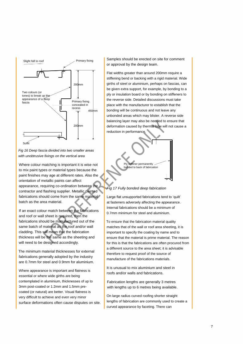
Slight fall to roof
Two colours (or
tones) to break up the
appearance of a deep
fascia
Primary fixing
200mm
Primary fixing
concealed in recess
450mm
200mm
Samples should be erected on site for comment
or approval by the design team.
Flat widths greater than around 200mm require a
stiffening bend or backing with a rigid material. Wide
girths of steel or aluminium, perhaps on fascias, can
be given extra support, for example, by bonding to a
ply or insulation board or by bonding on stiffeners to
the reverse side. Detailed discussions must take
place with the manufacturer to establish that the
bonding will be continuous and not leave any
unbonded areas which may blister. A reverse side
balancing layer may also be needed to ensure that
deformation caused by thermal bow will not cause a
reduction in performance.
Soffit
Fig 16 Deep fascia divided into two smaller areas
with unobtrusive fixings on the vertical area
Where colour matching is important it is wise not
to mix paint types or material types because the
paint finishes may age at different rates. Also the
orientation of metallic paints can affect
appearance, requiring co-ordination between the
contractor and flashing supplier. Metallic painted
fabrications should come from the same material
batch as the area material.
If an exact colour match between the fabrications
and roof or wall sheet is required, then the
fabrications should be manufactured out of the
same batch of material as the roof and/or wall
cladding. This will mean that the fabrication
thickness will be the same as the sheeting and
will need to be designed accordingly.
The minimum material thicknesses for external
fabrications generally adopted by the industry
are 0.7mm for steel and 0.9mm for aluminium.
Where appearance is important and flatness is
essential or where wide girths are being
contemplated in aluminium, thicknesses of up to
3mm post-coated or 1.2mm and 1.5mm pre-
coated (or natural) are better. Visual flatness is
very difficult to achieve and even very minor surface deformations often cause disputes on site.
Ply stiffener permanently
bonded to back of fabrication
Fig 17 Fully bonded deep fabrication
Large flat unsupported fabrications tend to ‘quilt’
at fasteners adversely affecting the appearance.
Internal fabrications should be a minimum of
0.7mm minimum for steel and aluminium.
To ensure that the fabrication material quality
matches that of the wall or roof area sheeting, it is
important to specify the coating by name and to
ensure that the material is prime material. The reason
for this is that the fabrications are often procured from
a different source to the area sheet; it is advisable
therefore to request proof of the source of
manufacture of the fabrications materials.
It is unusual to mix aluminium and steel in
roofs and/or walls and fabrications.
Fabrication lengths are generally 3 metres
with lengths up to 6 metres being available.
On large radius curved roofing shorter straight
lengths of fabrication are commonly used to create a
curved appearance by faceting. There can
7
4.0 Architectural details
be a tendency in doing this for the laps to ‘bird
mouth’ and butt straps shaped to accommodate
the faceting can be used to create better
flashing junctions.
Straight fabrications
in short lengths
Shaped butt strap
Fig 18 Curved fabrication
Where curved fabrications are needed these are
fabricated by the lock-form method or post-
coated, welded thick aluminium (2-3mm). The
sectional shapes for curved fabrications should
be kept as simple as possible with 90° angles.
The verge fabrications to curved roofs are the
most prominent and pre-curved fabrications will
provide the best appearance. It is a false
economy to skimp on the verge fabrications.
The use of lock-form steel/aluminium or welded/
post-coated thicker aluminium (2-3mm) will give
the best results.
The designer should specify these in the
project specification and insist on reference
samples for approval before installation.
Summary • General minimum thickness:
Internal use External use
Steel 0.4mm 0.7mm
Aluminium 0.7mm 0.9mm
• Maximum flat width between bends
200-250mm
• Use the same material coating
specification as the area material
• Avoid using dissimilar materials and
coatings compared to the area material
• Use prime materials and ask for proof
of source
• 3 metre common lengths, 6 metre maximum
4.1 Introduction Architectural fabrications are defined by the fact
that they are used on buildings for their visual
effect, in addition to any weatherproofing
function they may have.
They range in sophistication from two-dimensional
bent pre-coated steel fabrications to post-polyester,
powder coated welded aluminium complex
fabrications. Considerable expertise is required
to ensure that these will be compatible with the
cladding systems on the building and provide a
reliable long-term performance. MCRMA
member companies either possess that expertise
in-house or are able to recommend reliable
supplier companies.
As the photography in this section illustrates,
architectural fabrications provide striking visual
effects on a building and can on occasions have
more effect on the architectural aesthetic than the
cladding systems. Some of the major types in
common use are illustrated here, however, this is
by no means intended to be an exhaustive list.
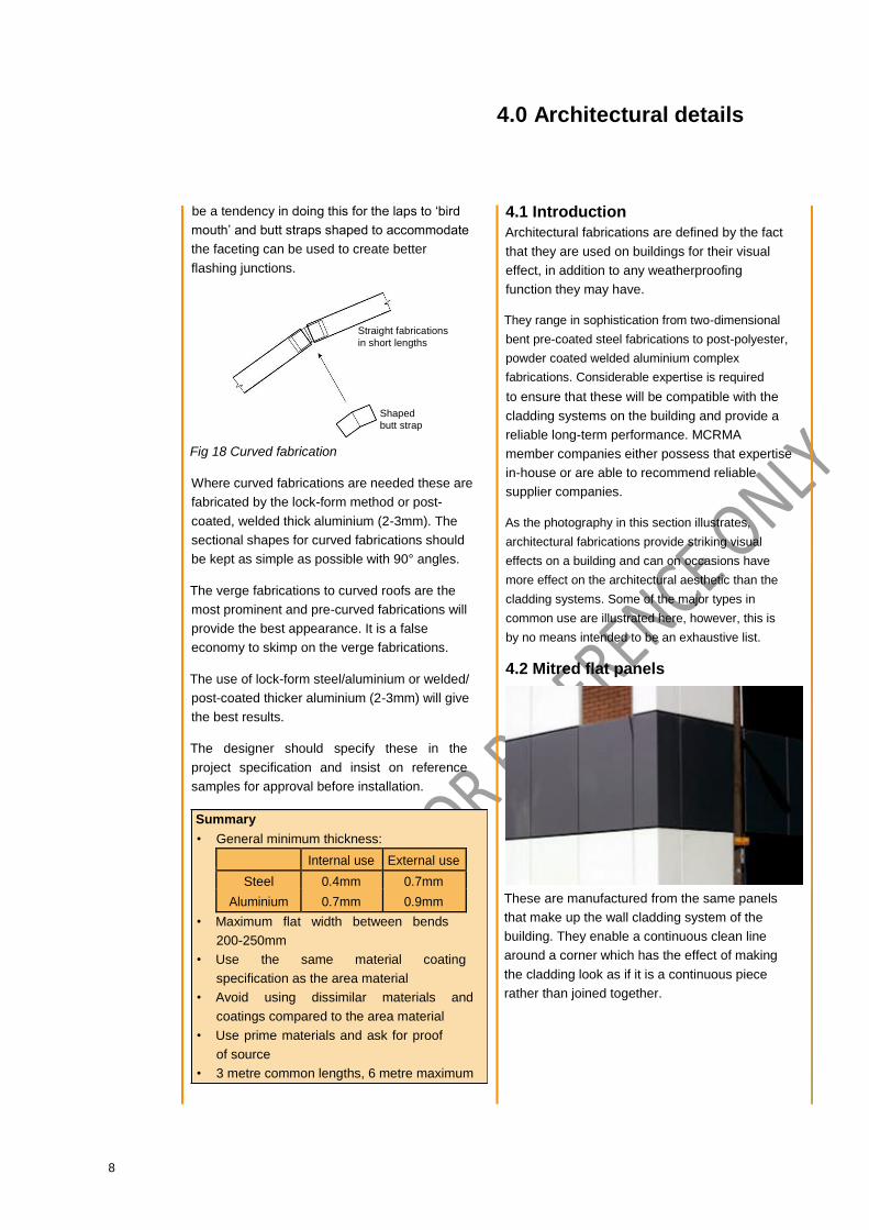
4.2 Mitred flat panels
These are manufactured from the same panels
that make up the wall cladding system of the
building. They enable a continuous clean line
around a corner which has the effect of making
the cladding look as if it is a continuous piece
rather than joined together.
8

4.3 Mitred profile corners
These corners are made to suit both built-up systems and composite panel cladding systems.
4.4 Bull noses
Circular curved fabrications used to create a
rounded feature on a building; they are often
used on the eaves.
4.5 Bull nose corners
Where two bull nose fabrications meet, a pre-
fabricated bull nose corner provides a neat
pre-engineered detail.
9

4.6 Wings, fins and aerofoils
These describe variations of bull nose fabrications
which instead of containing simple circular radii,
have variations for different visual effects.
4.7 Window surrounds
Window surrounds manage the interface between
cladding and window frames. They can be used
for purely functional purposes but also can
provide a striking visual feature.
4.8 Louvre systems
This is another example of form following function
and then taking it over. The function of louvres
is to provide ventilation, however they also give
what could otherwise be rather dull looking
planar buildings a more interesting presentation.
4.9 Curved fabrications
These are used, for example, to provide the end
detail to a curved roof. The range of applications
is extremely wide, however the curved
fabrication almost inevitably makes a strong
aesthetic statement.
10

4.10 Fascia and soffit systems
Fascias are used on vertical faces and soffits for
the underside of horizontal faces. These items
can be considered as either cladding and
fabrications, however they are mentioned here
because they are often used to create
architectural features to complement or contrast
with the main cladding system used.
11
5.0 Manufacture
Before any fabrication manufacture can be
undertaken the manufacturer must have agreed clear
working details giving the following information:
1 Girth 2 Length 3 Quantity
4 Thickness
5 Metal specification 6 Colour coating 7 Packing instructions (ie batching, if needed) 8 Sketch showing profile shape, dimensions
and angles, colour-coated surfaces, welts
9 Butt straps 10 Any special instructions for example, tapering
in length, dressing of welds.
11 Radius, if applicable
While the bulk of fabrication dimensions can
be pre-planned by the sub-contractor at the
working drawing stage, there will always be
some fabrications that have to rely on site-
measured dimensions before manufacture.
The designer needs to be aware of the restrictions
concerning minimum dimensions of fabrications to
be pressed or folded. Such dimensions vary from
machine to machine and fabricator to fabricator.
At the moment, standard tolerances on fabrication
dimensions at the manufacturing stage do not
exist. Also it is rare for the buyer to state what
tolerances will be acceptable to his company. The
following can be used as a guide:
Girth of fabrications in flat form prior to ± 2mm
folding
Dimension between folds (external or ± 1mm
internal dimensions must be specified)
Fold angle ± 2°
Length +0/-5mm
Fold radii are another aspect which must be
considered especially when dealing with thick
materials such as copings etc. The thicker the
material, the greater the internal radii.
Whether or not detailed or specified, it is good
practice to include a fold or welt to the
longitudinal edge of fabrications.
Summary • Provide the fabricator with a
complete specification
• Stiffen edges • Be aware of minimum fabrication dimensions
generally, and minimum radii for aluminium
12

6.0 Special requirements
for aluminium
The primary reasons for differentiating between
steel and aluminium fabrications is thermal
movement. The expansion and contraction rate of
aluminium is about twice that of steel and can
lead to the rupturing of fasteners and joints.
Movement should be assumed to occur and
allowed for in design and fixing.
6.1 Allowance for expansion A rule of thumb for thermal movement in
aluminium is 1mm per metre of length. For dark
colours this should be increased to 1.5mm per
metre. For example, a 3 metre flashing not in dark
colours needs an allowance of 3 x 1 = 3mm at
each end for movement.
Primary fixing to structure
3mm (nominal)
expansion gap, no
sealant pointing in gap
Butt strap stitched
and sealed to flashing
(of factory welded)
Expansion
allowance at joint
Butt strap does
not return under,
to prevent drips
staining wall Fig 19 Allowances for movement in
aluminium closed section fabrications
If expansion joints are not used and joints are
rigidly fixed, the fabrication will act like a very
long section amplifying the movement. For
example, four 3 metre sections fixed rigidly
together will act like a 12 metre fabrication with
12 x 1 = 12mm of expansion/contraction trying to
happen in a stiff material.
If the expansion/contraction is not allowed to
happen, temperature variations will cause thinner
fabrications to ripple and buckle, laps and
fasteners could weaken and leaks occur.
Ultimately, fabrications could detach. In extreme
cases, it has been known for rigidly fixed
aluminium fabrications to fracture.
A 3m fabrication will tend to expand from its
centre slotting fixing holes slightly and taking up
slack. The expansion gap at each end allows the
1.5mm or so movement to take place at each end
of the fabrication.
6.2 Design and installation The minimum aluminium thickness for fabrications
is 0.9mm. Where appearance is of prime
importance for example, on fascias, then consider
thicker aluminium (2-3mm, for example) and post-
painting to match, if necessary. Curved fascias may
need to be 3mm, welded, welds dressed and post-
painted. This tends to give a tidier appearance than
lock-formed thinner materials.
As a general guide, the unstiffened or unsupported
widths and material gauges in the table below can be
used. The lower limit should be adopted where high
aesthetic standards are required and the upper limit
where appearance is not critical (behind parapets,
for example). The mid range should be suitable for
most building purposes.
Gauge mm Unstiffened width mm
0.9 125-250
1.2 175-350
1.6 225-450
2.0 275-550
3.0 325-650
The maximum individual fabrications length should
generally be 3 metres and the widest visible
face flat between 125 and 250mm without a
stiffening bend (in 0.9mm aluminium). Aluminium
fabrications in 6 metre lengths can be used, but for
light colours only. For wider ridge fabrications
consider introducing additional bends (see fig 20).
Isolate aluminium fabrications from galvanised steel
supports using suitable self-adhesive PVC tape.
Fig 20 Wide ridge fabrications
13

Natural mill or stucco aluminium can give
aesthetically poor results with the slightest
undulation or imperfection appearing
prominent. Solid colours such as light grey
work better and match well with stucco roofs
although there is a variation, especially at first.
Note that metallic silver can also show
undulations and imperfections and that whilst
light grey can be considered with stucco, it does
not work with metallic silver.
Joints in open section fabrications should be
lapped. In closed section fabrications that do not
nest, joints should be butt strapped. Typical joint
details are shown below:
150mm (Roof) 100mm (Wall) min
Fall Lap joint
open section
Primary fixings fabrications to structure
Fall 3mm
Butt joint
closed section
150mm fabrications
Fixing is to
one side only
Fall
Lap joint with retainer zed
Primary fixings 150mm (Roof) 100mm (Wall) min to structure
Fig 21 Open section fabrications
6.3 Sealants Sealants can be readily divided into two types,
namely strip seals and gun grade sealants. Gun
grade sealants can include silicones, polyurethanes
and butyl rubber-based sealants. These have the
disadvantage of being readily over-compressed by the fasteners installed at the end laps which
reduces the effective thickness and therefore its
ability to accommodate movement. By
comparison, butyl strip sealants are less readily
over-compressed, should be appropriately sized
for the joint to be sealed and meet the
requirements of an NFRC Class A butyl sealant.
6.4 Welding One of the advantages of using aluminium is its
ability to be welded either in the factory or on site.
Welding may be by TIG, MIG, gas brazing or
soldering; TIG is currently the favoured method.
Welding is a specialist trade and must be
undertaken by fully trained and coded welders.
Complex intersections should be welded. These
form fixed points; ensure sufficient allowance has
been made for expansion between fixed points.
Ensure that there is no risk of fire if welding is to
be carried out on site that is, no backing paper,
loose vapour control layer or combustible
material concealed behind the weld area.
All operatives must stay clear of any welding
in progress because of the associated
hazards of welding glare, fume fever etc.
Note that aluminium does not change colour
when heated!
If the aluminium is pre-painted, the paint must
be removed at least 25mm away from the
welded area on both sides of the material. Also,
any cutting must be done by proper cutting tools
and not grinders. Failure to do this may lead to
weld inclusions and premature failure.
Welds must be visually checked for stop/start
worm holes, cold lap or inclusions which may lead
to premature failure and/or leaks. Non-destructive
testing may be carried out by trained people using
the dye penetration test or similar.
6.5 Fasteners To fix aluminium to thin flexible materials,
aluminium body rivets with stainless steel
mandrels or all stainless steel rivets are suitable.
Do not oversize holes, the correct pilot hole size is
important even with ‘Bulbtite’ or TLR type rivets.
When fixing fabrications to a rigid substrate with
screws, the holes in the aluminium should be
oversized by at least 2mm and large washers
used to allow flexure in the flashing length.
14
7.0 Penetrations
Stainless steel rather than carbon steel screws
must be used with aluminium fabrications. Fix
fabrications at 450mm maximum centres, or to
every rib, along their length.
6.6 Aesthetics Where aluminium fabrications are used and the
appearance is crucial, the architect’s approval of
a sample is prudent before the volume
manufacture of expensive welded/post-coated
items. This can be of the component or of the
made-up fabrication and intersection.
Penetrations in metal roofs create particular
design questions for their fabrications and there
are a variety of solutions.
7.1 Pipe fabrications Vent pipes and other relatively small penetrations
can be weathered using pre-formed EPDM or
silicone rubber pipe fabrications.
These contain a pliable aluminium strip around their
base which can be worked around the shape of the
roofing profile. The edge is bedded in a gun grade
sealant such as silicone and fixed with sealed rivets
or stitcher screws. The fixing kits must be obtained
from the pipe fabrication manufacturer.
The rubber soakers are adaptable to most profile
shapes and provide a good solution if applied well.
The pipe fabrications should be installed so that they
do not block any flutes of the roof sheet, as this
allows water to remain on the coating causing
premature deterioration and it unnecessarily tests
the sealants. Large diameter pipes should either be
installed on a flat back-lashing or specialised soaker
pipe fabrications are available.
Any back fabrications should extend to the ridge
and under no circumstances should laps other
than endlaps be used. Longitudinal laps in these
fabrications are not a satisfactory solution.
The collar should be in contact with the pipe
by 25mm and any spiral welds etc should
have sealant applied.
7.2 Profiled soakers In trapezoidal profiles, factory-made GRP or
aluminium soakers which provide a transition from
the profile shape to a flat leading to the upstand
can be used. These lap into the profile, with laps
being sealed as with normal end and side laps.
These are generally only suitable on pitches
greater than 5°.
Profiled soakers, if not manufactured from the
same material and paint finish as the roof, will
cease to have the same appearance after time
due to differential fade and ageing. This may not
be critical.
15

7.3 Back fabrications These flat sheets installed over the crown of the
roof sheet profile and laid over the roof sheet,
provide a convenient method of weathering
openings particularly with secret fix profiles at very
low slopes. The endlap between back fabrications
should be sealed with twin lines of sealant and
stitched with sealed rivets or screws at 75-100mm
centres. Longitudinal laps should not be used. The
back fabrications edges should be turned down
over the profile ribs.
On wide flute profiles, the use of appropriately
fire rated insulation board in the profile pans,
between the apron and roof profile, will help
support the apron and resist accidental damage.
A quilt insulation should be used in narrow flute
profiles and installed under the back flashing to
reduce the amount of condensation forming on
the underside of it.
7.4 On site welding A very effective method of introducing openings
on aluminium roof sheeting is to weld in an
aluminium soaker on-site. This can be used with
painted or natural aluminium with equal success.
On-site welding is a specialist operation and the
advice of a welding expert should be sought and
heeded. In particular, the designer needs to
consider thermal movement, weld edge support
by means of rigid rock fibre insulation, fire safety
and drainage from behind the soaker.
It is feasible to introduce penetrations by the use
of on-site welding after the general roof area has
been installed. The specialist welder will
normally cut the opening, take fire precautions,
seal vapour control layers and ensure continuity
of insulation, as well as installing kerbs, trimmers
and soakers and welding the soaker in.
7.5 On site GRP A method with similar attributes to the on-site
welding of aluminium is the use of site-applied GRP
on steel roofing to weather an opening. This is
another specialist operation in which the advice of
an expert applicator should be sought and
heeded. Corus has carried out investigations into
site-applied GRP used with Colorcoat HPS200 and
is satisfied with regard to material compatibility.
The designer will need to consider drainage
around the opening, the long term durability of
GRP, support to the bond area and differential
colour ageing.
As with welding, it is feasible to introduce
openings after the general area of roofing has
been installed. Again, the complete procedure is
carried out by the specialist.
7.6 General With all methods of weathering openings, the
early planning of opening positions will allow
the best detailing. Structural trimmers need to
be introduced, the vapour control layer needs
to be made continuous (that is, sealed to the
opening surrounds). Openings are ideally
positioned as close to the ridge as possible, in
line upslope (or not placed in the roof at all!).
Penetrations installed after completion of the
roof area will need a trimmer to provide support
to the surrounding roof and continuity of seal of
the vapour control layer.
Attention should be paid to the prevention of
cold bridging and to the continuity of insulation.
16

8.0 Workmanship
8.1 Good housekeeping Materials must be stored off the ground preferably
undercover and secured against the wind.
Protect against trapped moisture and do not
store near to access ways.
Avoid impact damage during fixing, especially
from riveting tools.
Do not twist fabrications and avoid
dragging sections over each other.
Ensure that the correct section is in the correct
place and take care in handling sharp edges. Do
not force sections into shape especially at folds
or weld lines.
Butt straps can be fitted at ground level where
they can be well supported to avoid distortion
when drilling and riveting. This is especially
applicable to aluminium fabrications.
Do not walk on fabrications, either in storage or when
fixed, and store away from lines of foot traffic.
Notify the main contractor that walking or
standing on finished fabrications is to be avoided.
When working on a fabrication on an aluminium
roof, work from a board to avoid over-deflecting
the roof sheet or damaging coatings.
Provide boarding for foot traffic in work areas,
provide edge protection and provide signs that is,
warning signs around fragile areas, rooflights etc.
Clear drill swarf and rivet mandrels as work
progresses, do not allow steel swarf to get wet.
Do not store cardboard boxes of fasteners on
roofs and only have enough fasteners for the job
in the work area.
Dispose of any fabrication off-cuts, clear work
area as work progresses and protect work from
any follow-on trades, especially wet trades.
Store tools safely when not in use.
8.2 Tools There are five sets of tools necessary to carry
out fabrications work:
Cutting saw, nibbler, shear head snips etc
Hole forming drill, punch etc
Measuring tape, rule, set square, pencil
Fastening lazy tongs, riveter, screw gun etc
Shaping hammer, wide nosed pliers etc
Where electrical tools are used, they must be suitable
for 110V site systems and fitted with safety plugs. All
electrical tools must be regularly checked and tagged
in accordance with the Electrical Regulations. Repairs
to electrical equipments must be carried out by
trained personnel only.
Certain tools, especially cutting and hole
forming tools, require the use of adequate
personal protection equipment such as goggles
or face mask, ear defenders, gloves etc.
Obviously, the range of tools available is enormous.
The type of tools will depend generally on the
preference of the user. Certain tasks
may mean that special proprietary tools must be
used. Whatever the case, the tool must be fit for
purpose; the misuse of tools can be both costly
and dangerous.
When cutting and drilling, it is good and safe
practice to remove sharp edges and burrs.
Grinding tools used for cutting tend to produce
greater burrs and coating damage than shears or
cutting blades and are not to be used.
With power cutting, the operator should consider
the problem of noise and ensure that he and
others in close proximity use ear protection.
When drilling, it is good practice to use a neoprene
sealed washer at the chuck face of the drill to avoid
drill damage to the fabrication. Care must be taken
when applying force to a drill as sudden penetration
may result in fabrication indentations. It is also good
practice to pre-punch drill holes to prevent the drill bit
slipping across paint faces, and the
17

materials should be well supported. Swarf must
always be removed from the roof.
Cutting tools should be guided along straight
edges for the best finish. Cables must be clear of
any cutting areas. A good cut can be achieved by
cutting bulk waste away with power tools and
finishing the work with hand snips, gilbows or similar.
Hand snips can be left or right-handed depending on
which side the waste is being removed. Screw guns
operate in the same manner as a drill.
Care must be taken not to over-tighten fasteners
or drive them home too fast, thus stripping the
thread (use a depth stop). As with a drill, too much
pressure at the wrong time may lead to fabrication
indentations.
Rivets are installed by either lazy tongs or lever
arm riveting tools, Lazy tongs work by an operator
‘punching’ action, which can lead to fabrication
indentation if misused. It is normally good practice
to start pulling the head of the rivet gun away from
the rivet prior to the fracture of the rivet mandrel.
No matter what the tool used, the sudden fracture
of a rivet mandrel can have disastrous results on
the finished appearance of a fabrication.
8.3 Fasteners The choice of fastener is between screws
and rivets; the choice being based upon
function, strength and desired appearance.
Screws are generally used to fix elements back to
supports however, some screws are available that
‘stitch’ sheets or fabrications together. Stitcher
screws are not as common as rivets for fixing
sheet materials together because of their
appearance above the cladding materials.
In all cases, the manufacturer’s information
regarding pilot hole size (where needed), material
compatibility and strength should be consulted prior
to specification. Sometimes it is necessary to
oversize holes for screw fasteners in the items to be
secured, especially in aluminium fabrications to
allow for expansion. It must be noted that oversizing
of rivet holes is not permissible even when using
Bulbtite or TLR type rivets.
When using screw fasteners on fabrications,
sealed washers should be used to give a
weathertight fixing. For the washer to work
properly, it must not be over or under compressed.
The most common type of fastener is a blind sealed
rivet. These offer a durable weathertight finish when
installed correctly. Bulbtite or TLR rivets
are popular since they tend to be more efficient
at clamping materials.
For aesthetic purposes, most fasteners can be
fitted with plastic caps although the site-fitted
caps do not tend to last very long. Alternatively,
rivets are now available factory-coated to match
adjacent fabrications, or screws with integral
plastic heads can be used provided that they are
acceptable to the design team.
Take care not to dimple a fabrication while drilling.
Pre-punching the hole is useful to avoid skid of the
drill bit. Care is also needed during pulling a rivet
not to dimple the fabrication when the mandrel
breaks. Support the butt strap and fabrication
while drilling and riveting to avoid distortion – this
may mean attaching butt straps at ground level.
8.4 Site measurement and setting out Site-measured fabrications and components such
as intersections offer the best appearance but
take time which is not always available.
Fabrications are usually delivered to site as part
of the materials package and are often made to
fit regardless.
Fabrications that offer greater flexibility in
installation tend to be the favoured type
whereas close tolerance products are
unforgiving if the structure is out of line.
There is no substitute for preparing and setting out
the job properly. The quality of the finish is directly
proportional to the amount of time spent on
achieving the right finish. Badly fixed fabrications
will detract from the overall appearance of a
project and could cause leakage. Therefore, it is
essential that fabrications are lined in with a string
line and squared up using a level.
18

9.0 Problem-solving
Symmetrically set out fabrications give a better
appearance. Three 2.5m lengths look better than
two 3m lengths plus a 1.5 make-up piece. Short
lengths of 1.5m or less used to finish a run of
fabrications seem not to lie flush and can
therefore mar the finished effect.
Where the appearance of a fabrication is important
to the success of a building, the specifier should
make it clear in his preliminaries that the installer
is responsible for the design and installation of the
fabrication to the satisfaction of the specifier. If the
appearance of the fabrications are considered to
be of prime importance, then the specifier should
also request and approve samples of the
fabrications and joints prior to manufacture,
perhaps installed on a reference mock-up on site.
Unbalanced fabrications
Symmetrical setting out
Fig 22 Setting out of fabrications
Packs or shims are not common but their use
may be considered in areas where the supports
are misaligned.
It is always advisable to check the supports prior
to fixing any fabrication to determine high and
low points. If the points are found to be in excess
of 5mm from the string line for example, shims
or packers should be considered at fixing points.
Intersections and corners can be specially fabricated
on site or in the factory with short leg lengths. Where
appearance is important factory-made corners and
end closers are the best choice, as it can be difficult
to achieve a professional finish with site-made
corners, unless made skilfully.
Since most complaints of water ingress or poor
appearance can be traced back to fabrications,
the more common causes are listed below:
Sealant - too little
- too much - incomplete - incorrectly positioned - wrong type
Fastening - too few
- leakage at fixing - thermal movement at fixing - poorly installed - part installed rivets - too close to edge - spacing
Foot traffic - deformation of fabrication
- joints/fixings ruptured
Repairs - fixing holes not plugged
Appearance - architect/designer not satisfied
with appearance - oil canning - water staining - poor corner detailing
Stiffeners - lack of stiffened edges or turn
downs - too large a flat area without stiffening
Joints - lapped joints ‘bird mouth’
- no allowance for thermal movement
Material - too thin/thick
- paint finish different to main areas resulting in colour variation - poor post-painting (lack of etch priming etc)
Cut edges - sheet edges cut with angle grinder
Roof - ends/edges of low pitch roof
sheets under fabrications not turned up, or fillers missing
19

Most, if not, all of these faults can be avoided
by the following:
• Appropriate fixer training • Improved design • Detailing • Supervision • Ensuring that design information gets to
the supervisor and fixer on site.
Fig 23 examples of good practice
20

MCRMA technical papers
No 1 Recommended good practice for daylighting in metal clad buildings
No 2 Curved sheeting manual
No 3 Secret fix roofing design guide
No 4 Fire and external steel-clad walls: guidance notes to the revised Building Regulations, 1992 (out of
print)
No 5 Metal wall systems design guide No 6
Profiled metal roofing design guide
No 7 Fire design of steel-clad external walls for building: construction, performance standards and
design
No 8 Acoustic design guide for metal roof and wall cladding No
9 Composite roof and wall cladding panel design guide
No 10 Profiled metal cladding for roof and walls: guidance notes on revised Building Regulations 1995
parts L & F (out of print)
No 11 Flashings for metal roof and walls: design, detailing and installation guide
No 12 Fasteners for metal roof and wall cladding: design detailing and installation guide
No 13 Composite slabs and beams using steel decking: best practice for design and construction No
14 Guidance for the design of metal roofing and cladding to comply with Approved Document L2:
2001
No 15 New Applications: composite construction
No 16 Guidance for the effective sealing of end lap details in metal roofing constructions.
No 18 Conventions for calculating U-values, f-values and -values for metal cladding systems using
two- and three-dimensional thermal calculations.
Please note: Publications can be downloaded from the MCRMA web site at www.mcrma.co.uk
Liability Whilst the information contained in this design guide is believed to be correct at the time of going to press, the Metal Cladding and
Roofing Manufacturers Association Limited and its member companies cannot be held responsible for any errors or inaccuracies and,
in particular, the specification for any application must be checked with the individual manufacturer concerned for a given installation.
The diagrams of typical constructions in this publication are illustrative only.
21

Metal Cladding & Roofing Manufacturers Association Ltd
106 Ruskin Avenue Rogerstone Newport South Wales NP10 0BD
01633 895633 | [email protected] | www.mcrma.co.uk