Embed Size (px)
Citation preview

Master of Science ThesisStockholm, Sweden 2009
TRITA-ICT-EX-2009:96
F R E D R I K E I D L E R T
Messaging and positioning in adynamic TETRA environment
K T H I n f o r m a t i o n a n d
C o m m u n i c a t i o n T e c h n o l o g y

Messaging and positioning in a dynamic TETRA
environment
Master’s thesis at the School of Information and Communication Technology
FREDRIK EIDLERT
2009-08-01
Examiner and academic advisor:
Professor Gerald Q. Maguire Jr.


i
Abstract
Advanced communication with capabilities such as voice, data, and messaging usually
requires an infrastructure with base stations, servers, and etcetera. The TETRA
technology offers such communication not only in TMO (infrastructure-based network)
but also in DMO where all nodes communicate directly (or via a repeater) with each
other.
This master’s thesis concerns messaging (specifically short messages) in a dynamic
multi link TETRA DMO network. It examines what type of messaging technique to use
and how to do path selection. The messages will be clear text, status, and GPS location
information. The solution is implemented as a part of the ISIS software (which is
developed by Know IT Dataunit). The planned multi link-part of the thesis could not be
tested, so there is no implementation or evaluation of this.
The evaluation of the implementation concerning sending and reception of messages
shows that the proposed solution fulfils the demands for this kind of product. During a
four day long test, messages (short text messages and positioning messages) were sent
and received while a normal number of voice conversations took place, without packet
loss.

ii
Sammanfattning
Avancerad kommunikation med funktioner såsom röstsamtal, dataöverföring samt
meddelandetjänster kräver ofta en infrastruktur med basstationer, servrar etcetera.
TETRA-tekniken erbjuder sådan kommunikation, inte bara i TMO
(infrastrukturbaserade nätverk), utan även i DMO där alla noder kommunicerar direkt
(eller via en repeater) med varandra.
Detta examensarbete undersöker hanteringen av meddelanden (framförallt korta
meddelanden) i ett dynamiskt multilänkat TETRA nätverk. Det som behandlas är vilken
typ av meddelande som bör användas samt hur man väljer väg. De meddelanden som
hanteras är klartextmeddelanden, status samt GPS positionsmeddelanden. Den lösning
som tagits fram är implementerad som en del i ISIS programvaran (som är utvecklad av
Know IT Dataunit). Multilänkdelen kunde inte testas, därför gjordes aldrig någon
implementering eller utvärdering.
Utvärderingen av implementeringen som hanterar sändning och mottagning av
meddelanden visar att den föreslagna lösningen uppfyller de krav man kan ställa på en
sådan produkt. Under ett fyra dagar långt test skickades meddelanden (korta
textmeddelanden samt positioneringsmeddelanden) medan ett normalt antal röstsamtal
pågick, utan någon förlust av paket.

iii
Acknowledgments
I would like to thank all the people that have helped med during this thesis project. My
supervisor and examiner at KTH, Professor Gerald Q. Maguire Jr.; Patrik Lander at
FM/LedR; and Maria Holmberg at FMV for all help with the TETRA hardware. John
Karlsson, Jonas Berg, and Stefan Andrén at Know IT Dataunit for all their discussion of
ideas and help with problems during the software implementation.

iv
Table of contents
Abstract ............................................................................................................................. i
Sammanfattning ................................................................................................................ ii
Acknowledgments ........................................................................................................... iii
Table of contents ............................................................................................................. iv
List of figures .................................................................................................................. vi
List of tables ................................................................................................................... vii
Definitions and abbreviations ........................................................................................ viii
Definitions ................................................................................................................. viii
Abbreviations ............................................................................................................ viii
1. Introduction ............................................................................................................... 1
1.1 Objectives ................................................................................................................ 1
1.2 Know IT Dataunit .................................................................................................... 2
1.3 Thesis outline .......................................................................................................... 2
2. Introduction to ISIS ................................................................................................... 3
2.1 Alfa message type ................................................................................................... 4
2.2 Format conversion plugins ...................................................................................... 5
2.3 Links ........................................................................................................................ 5
2.4 Function chains ........................................................................................................ 6
3. Introduction to TETRA ............................................................................................. 7
3.1 Interfaces ................................................................................................................. 7
3.2 Channels .................................................................................................................. 8
3.3 Addressing ............................................................................................................... 9
3.4 Short Data Services (SDS) .................................................................................... 10
3.4.1 Short Data Services Transport Layer (SDS-TL) ............................................ 11
3.5 Repeaters ............................................................................................................... 12
3.6 Peripheral Equipment Interface (PEI) ................................................................... 14
3.7 Positioning ............................................................................................................. 14
3.7.1 Location Information Protocol (LIP) ............................................................. 14
3.7.2 National Marine Electronics Association (NMEA) 0183 over SDS-TL ........ 15
4. Introduction to RAKEL ........................................................................................... 16
4.1 Positioning in RAKEL .......................................................................................... 17
4.2 RAKEL WIS ......................................................................................................... 17
4.3 Security in RAKEL ............................................................................................... 17
5. Introduction to the Sepura SRH-3800 sGPS TETRA terminal ............................... 18

v
5.1 Programming and configuration of the TETRA terminal ..................................... 18
6. Introduction to routing in ad hoc networks ............................................................ 20
6.1 Greedy Perimeter Stateless Routing (GPSR) ....................................................... 20
6.2 Movement-Based Routing Algorithm (MORA) ................................................... 20
6.3 Movement Prediction-Based Routing (MOPR) .................................................... 20
7. Related work ........................................................................................................... 21
7.1 Monitoring and Control of Secondary Substations .............................................. 21
7.2 Performance of TETRA Short Data Service-Transport Layer ............................. 21
7.3 Effects of SDS-TL message length on QoS metrics ............................................. 21
7.4 UDP Performance Measurements over TETRA IP .............................................. 22
7.5 Impact of Voice Traffic on the Performance of Packet Data Transmission in
TETRA networks ........................................................................................................ 22
8. Proposed solution.................................................................................................... 23
8.1 Message technology .............................................................................................. 23
8.2 Message type ........................................................................................................ 23
8.2.1 LIP reporting interval .................................................................................... 24
8.3 Path selection ........................................................................................................ 24
8.3.1 Polling ............................................................................................................ 25
8.3.2 Reading of relaying repeater address ............................................................. 26
8.3.3 Geographical position .................................................................................... 26
8.4 Hardware configuration ........................................................................................ 27
9. Implementation ....................................................................................................... 28
9.1 TETRA hardware .................................................................................................. 28
9.2 ISIS plugins .......................................................................................................... 28
9.2.1 TETRA Format Conversion Plugin ............................................................... 28
9.2.2 TETRA Link .................................................................................................. 29
9.2.3 TETRA Function Chain ................................................................................. 29
10. Conclusions.......................................................................................................... 30
10.1 Messaging and positioning in a multipath DMO network .................................. 30
10.2 Messaging and positioning in a TMO network .................................................. 30
11. Future work .......................................................................................................... 33
References ....................................................................................................................... 34

vi
List of figures
Figure 1.1: Illustration of a multi link TETRA DMO network ......................................... 2
Figure 2.1: ISIS connections ............................................................................................. 3
Figure 2.2: Illustration of how the Format conversion plugin, the Function chains, and
the Links are connected ..................................................................................................... 4
Figure 2.3: Mandatory content of an Alfa Received Target message ............................... 5
Figure 3.1: TETRA network interfaces ............................................................................. 7
Figure 3.2: TDMA timeslot usage in frequency efficient mode ....................................... 8
Figure 3.3: Contents of TSI ............................................................................................... 9
Figure 3.4: Content of a SDS STATUS message ............................................................ 10
Figure 3.5: Illustration of SDS-TL text message ............................................................ 11
Figure 3.6: DMO Repeater type 1a ................................................................................. 13
Figure 3.7: DMO Repeater type 1b ................................................................................. 13
Figure 3.8: DMO Repeater type 2 ................................................................................... 13
Figure 3.9: Contents of LIP short location report message ............................................. 15
Figure 4.1: Deployment of RAKEL in Sweden .............................................................. 16
Figure 5.1: Sepura SRH-3800 sGPS TETRA Terminal .................................................. 18
Figure 5.2: Standby screen in DMO mode, Sepura SRH-3800 TETRA Terminal ......... 18
Figure 5.3: Setting GPS parameters in Sepura Radio Manager software ....................... 19
Figure 6.1: Example of Greedy routing. The red dot is the closest neighbor ................. 20
Figure 8.1: Illustration of possible states of path to destination ...................................... 25
Figure 8.2: Illustration of geographical repeater selection .............................................. 27
Figure 10.1: Graphic presentation of located TETRA terminals during the military
exercise in Enköping, Sweden in May 2009 ................................................................... 32
Figure 10.2: Soldier equipped with Sepura SRH-3800 TETRA Terminal and a remote
speaker microphone ......................................................................................................... 32
Figure 10.3: Company headquarters using the location services .................................... 32

vii
List of tables
Table 2.1: Message formats understood by ISIS .............................................................. 3
Table 3.1: TETRA network interfaces .............................................................................. 7
Table 3.2: Content of a SDS STATUS message ............................................................ 10
Table 3.3: SDS message types ........................................................................................ 11
Table 3.4: Contents of SDS-DATA PDU ....................................................................... 12
Table 3.5: Contents of SDS-TRANSFER PDU ............................................................. 12
Table 3.6: Contents of SDS-TL text message ................................................................ 12
Table 3.7: Contents of LIP short location report message .............................................. 15
Table 8.1: Possible states of path to destination ............................................................. 25

viii
Definitions and abbreviations
The following definitions and abbreviations have been used in this thesis.
Definitions
LC This term denotes a PC connected to a TETRA terminal acting as
command and control system.
Abbreviations
ACP Allied Communication Publications
AIS Automatic Identification System
AS Area Selection
ASTERIX All Purpose Structured Eurocontrol Surveillance Information Exchange
ATSI Alias TETRA Subscriber Identity
C2 Command and Control
CP Called Party
CPTI Called Party Type Identifier
DART DataRapporteringsTerminal
DGPS Differential Global Positioning System
DM Direct Mode
DM-REP Direct Mode Repeater
DMO Direct Mode Operation
DRR Delivery Report Request
ETSI European Telecommunications Standards Institute
EXT Extension
FM Försvarsmakten
FM-IP Försvarsmaktens Internetprotokoll
FMV Försvarets Matrielverk
GPS Global Positioning System
GPSR Greedy Perimeter Stateless Routing
GTSI Group TETRA Subscriber Identity
HF 2000 Automated High Frequency radio system
ISIS Integrerat SambandsInformationsSystem
ITSI Individual TETRA Subscriber Identity
ITU-T International Telecommunication Union - Telecommunication
Standardization Sector
LCH Linearization Channel
LEN Length
LIP Location Information Protocol
LuLIS LuftLägesInformationsSystem
MCC Mobile Country Code
MNC Mobile Network code

ix
MOF Militärt Operativt Format
MOPR Movement Prediction-Based Routing
MORA Movement-Based Routing Algorithm
MTN Marinens Telenär
MS Mobile Station
MSB Myndigheten för samhällsskydd och beredskap
MSG Message
M.TYPE Message Type
NATO North Atlantic Treaty Organization
NMEA National Marine Electronics Association
PEI Peripheral Equipment Interface
PFF Partnerskap För Fred
PD Packet Data
PDO Packet Data Optimized
PDU Packet Data Unit
PI Protocol Identifier
PMR Professional Mobile Radio
QoS Quality of Service
RAKEL RadioKommunikation för Effektiv Ledning
REF Reference
RF Radio Frequency
SAAB Svenska Aeroplan AB
SCH Signalling Channel
SDS Short Data Services
SDS-TL Short Data Services Transport Layer
SDTI Short Data Type Identifier
SIM Subscriber Identity Module
SMTP Simple Mail Transfer Protocol
SNA Short Number Addressing
SR Short Report
SS Service Selection
SSI Short Subscriber Identity
STCH Stealing Channel
SUCFIS Sea Surveillance Cooperation Finland-Sweden
TCH Traffic Channel
TCS Text Coding Scheme
TDMA Time Division Multiple Access
TEA TETRA Encryption Algorithm
TEDS TETRA Enhanced Data Service
TETRA Terrestrial Trunked Radio
TMO Trunked Moder Operation
TNP1 TETRA Network Protocol type 1
TS Time Stamp

x
TSI TETRA Subscriber Identity
UDP User Datagram Protocol
UHF Ultra High Frequency
URT Usage Restriction Type
VANET Vehicle Ad-hoc Network
VHF Very High Frequency
VLF Very Low Frequency
WIS Web based Information System

1
1. Introduction
ISIS (Integrerat SambandsInformationsSystem) is the name of a computer software
developed by Know IT Dataunit for use within military command systems. The ISIS
software contains functions for messaging over many different media, but at the start of
this thesis project could not operate over TETRA (Terrestrial Trunked Radio). Since the
Swedish Police and other government authorities use the TETRA based network
RAKEL (RadioKommunikation för Effektiv Ledning) [1] it was desirable to design and
implement the necessary functionality to support liason between the Swedish military
and the civil government authorities.
TETRA is a Professional Mobile Radio (PMR) standard that was designed by the
European Telecommunications Standards Institute (ETSI) to be used by government,
emergency services, transport services, and the military. The first TETRA release was
completed in 1994. To meet higher user demands work on TETRA Release 2 began in
1999, and was finished at the end of 2005.
TETRA Direct Mode Operation (DMO) allows TETRA devices to communicate
directly with each other (i.e., there is no need for any infrastructure) - enabling a group
of TETRA nodes to form an ad hoc network. This network can be extended by multiple
repeaters (i.e., utilizing multi-hop routing) to allow for rapid and dynamic deployment
of a network. Such network can be used for sending orders to military units and
receiving their positions and for other purposes. It is possible to dynamically add and
remove repeaters and nodes to this network without the need for reconfiguration. Thus
such a network is very well suited for users “on the move”.
The implementation of Short Data Services (SDS) messaging in DMO and Trunked
Mode Operation (TMO) are done in the same way, hence the results of this thesis
project should be applicable in TMO networks.
1.1 Objectives
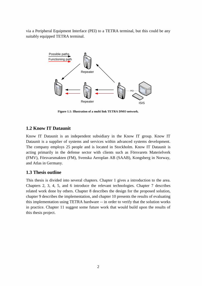
The goal of this thesis project is to provide a solution for sending and receiving
messages in a dynamic multi link TETRA DMO network. Note that in this thesis we
consider message distribution via multiple paths between the source and destination --
in order to increase the probability of successfully delivering a message to its
destination despite changes in the network topology. We will refer to a network which
offers multiple paths between the source and destination as be a multi link TETRA
DMO network (see Figure 1.1). These messages will be either GPS positions (which are
sent from the Mobile Station (MS) to the ISIS) or orders which are sent in the opposite
direction. Parts of the solution will be implemented as a plug-in to the ISIS system and
verified by testing the implementation with TETRA-hardware. Thus in this thesis we
will focus on communication where the ISIS is either the sink (message are sent to it as
a destination) or source (message are sent from the ISIS to a MS). The ISIS is connected
2
via a Peripheral Equipment Interface (PEI) to a TETRA terminal, but this could be any
suitably equipped TETRA terminal.
Repeater
ISIS
PEI
Repeater
Possible paths
Functioning path
Figure 1.1: Illustration of a multi link TETRA DMO network.
1.2 Know IT Dataunit
Know IT Dataunit is an independent subsidiary in the Know IT group. Know IT
Dataunit is a supplier of systems and services within advanced systems development.
The company employs 25 people and is located in Stockholm. Know IT Dataunit is
acting primarily in the defense sector with clients such as Försvarets Materielverk
(FMV), Försvarsmakten (FM), Svenska Aeroplan AB (SAAB), Kongsberg in Norway,
and Atlas in Germany.
1.3 Thesis outline
This thesis is divided into several chapters. Chapter 1 gives a introduction to the area.
Chapters 2, 3, 4, 5, and 6 introduce the relevant technologies. Chapter 7 describes
related work done by others. Chapter 8 describes the design for the proposed solution,
chapter 9 describes the implementation, and chapter 10 presents the results of evaluating
this implementation using TETRA hardware -- in order to verify that the solution works
in practice. Chapter 11 suggest some future work that would build upon the results of
this thesis project.

3
2. Introduction to ISIS
The ISIS software connects the Command and Control (C2) (and similar systems) to
external communication links (see Figure 2.1). The ISIS software converts messages
into the appropriate format for sending to and receiving from remote users. More
specifically, ISIS converts to and from the generic internal message type Alfa (see
Section 2.1) which is used for communication between ISIS and the C2 system. As a
result, C2 is independent of the technology and message format used for communication
over any of the different types of communication links. Today ISIS has support for the
following link technologies:
FM-IP-net [2]
MTN [2]
VHF/UHF, HF, VLF [2]
HF 2000 [2]
ISIS
Staff support
C2
External
links
Figure 2.1: ISIS connections
In addition to the above link technologies ISIS supports the message formats shown in
Table 2.1.
Table 2.1: Message formats understood by ISIS [2].
MOF Militärt Operativt Format ACP 127 Allied Communication Publications 127
DART DataRapporteringsTerminal Unformatted text
IP 8000
LuLIS LuftLägesInformationsSystem
LvMÅDS LuftvärnsMålDataSystem
AIS Automatic Identification System
ASTERIX category SUCFIS
xAlfa External Alfa
SMTP Simple Mail Transfer Protocol

4
ISIS also handles configuration and control of the hardware used for the external links.
This external hardware could be crypto hardware or a radio modem which needs to be
configured to use the correct frequency and the corresponding antenna [2].
The conversion between the internal message format Alfa and the supported message
formats is done with format conversion plugins (see Section 2.2), the hardware control
is done with links (see Section 2.3), and to connect a Link to ISIS a function chain is
needed (see Section 2.4). See Figure 2.2 for an illustration of how the Format
conversion plugin, the Function chains, and the Links are connected.
ISIS
Format
conversion
plugin
Function
chainsLinks
Figure 2.2: Illustration of how the Format conversion plugin, the Function chains, and the Links are
connected.
Other functions in ISIS are the expedition service and the address database. The
expedition service is used to create and read messages. The address database contains
information about how communication can and should be established with the military
units addressed in the database. This database also holds basic information about these
units.
2.1 Alfa message type
The Alfa message is used internally in ISIS and over the connection between ISIS and
the C2 system. An Alfa message is a generic message type along with sufficient
information to be converted into any of the supported message types shown in Table 2.1
[2]. The content of an Alfa message vary, depending on what type of message is
contained in the Alfa message. All messages have an Administrative header, a send or
reception header, and content. The content is an object that contains another set of
elements. There are several mandatory fields and many optional fields. The list of
possible content types is long (see [8] for a list). Figure 2.3 shows an example of an
Alfa message with a Received Target object as content.

5
Adm.
header
Reception
header
Target
object
Reception id
Sender
Addressees
Ack request
Tracknumbers
Compiled picture
Simulation status
Measurement
time
Position
Figure 2.3: Mandatory content of an Alfa Received Target message [8]
Administrative Header Contains message sequence number
Reception Header
Reception ID Used to map a specific reception with the transmission
request of an ack.
Sender Alfa ID of sender
Addressees List of Alfa IDs
Acknowledge request Flag indicating true/false
TargetObject
Tracknumbers List of Tracks
Compiled picture Flag indicating compiled or from a sensor
Simulation status Flag indicating simulated or real data
Measurement time UTC Time of measure
Position Position in WGS 841 coordinates
The other message types are built in the same way, but have other mandatory and
optional fields. Complete details can be found in [8].
2.2 Format conversion plugins
For every format that ISIS handles there is a format conversion plugin. The task for a
format conversion plugin is to convert between the specific format and Alfa. This
conversion plugin maps all fields of the Alfa message to the corresponding fields in the
other format. Each format might have a number of different message types which have
to be recognised and correctly converted into and out of the corresponding Alfa
message.
2.3 Links
All hardware connections that ISIS handles have a (local) link. This link handles all
communication with the hardware, this includes: initialization, configuration, and
sending or reception of a message.
1 ://en.wikipedia.org/wiki/WGS84

6
2.4 Function chains
A function chain connects a Link to ISIS. The function chain contains methods for
setting up the Link and to configure the Link (do not confuse with hardware
configuration which is done by the Link). One (or more) of the created chains are
chosen as communication method for each specific addressee by the ISIS software.

7
3. Introduction to TETRA
A TETRA system can handle both voice and data communication over either a trunked
network (Trunked Mode Operation -TMO) or over a network where the mobile stations
(MS) communicate directly with each other (Direct Mode Operation - DMO). There is
also a standard for a Packet Data Optimized (PDO) network, as a data only network.
There are not yet any PDO products on the market because current users require both
voice and data support [4]. The changes in Tetra Release 2 (from Release 1) are
extended range (this only applies to TMO networks), two additional voice CODECs,
and high speed data service called: TETRA Enhanced Data Service (TEDS) [4].
3.1 Interfaces
The TETRA standard defines a number of interfaces so that products from different
manufacturers will work together (i.e., interoperate). These interfaces are listed in Table
3.1 and shown in figure 3.1.
Table 3.1: TETRA network interfaces [3].
I1 Air interface
I2 Line station interface
I3 Inter-system interface
I4 Peripheral Equipment interface for mobile station
I4’ Peripheral Equipment interface for line station
I5 Network management interface
I6 Direct mode air interface
I1
I6I3
TETRA
network
A
TETRA
network
B
I4 I2I5
Network
management
I4'
Figure 3.1: TETRA network interfaces [3].
Because this thesis will focus on DMO and the connection between a PC and a MS
(using PEI) we will not further refer to TMO or PDO, thus interfaces I1, I2, I3, and I5
are outside the scope of this thesis. This leaves only interfaces I4, I4', and I6.

8
The DMO Air interface (I6) uses Time Division Multiple Access (TDMA) with 4
timeslots. These timeslots corresponds to either one or two channels depending on
whether frequency efficient mode is used. Channels in DMO are further explained in
Section 3.2.
In a DMO network communication between MSs is either directly between MSs or via
a repeater. Repeaters operating in DMO are further explained in Section 3.5. Direct
communication uses the I6 interface described above.
The Peripheral Equipment Interface (PEI) (I4) is used to connect additional hardware
(for example a PC) to a MS. The PEI is described in Section 3.6. Similarly the I4'
interface enables additional hardware to be connected to a line station (such as a PC).
3.2 Channels
TETRA DMO uses a single radio frequency (RF) carrier which is split into channels by
using TDMA with 4 timeslots. Depending on if frequency efficient mode is used, either
one or two channels exist. Timeslots 1 and 3 are used for the call and slots 2 and 4 are
for safety so that the MS has time to switch between transmitting and receiving. In the
case of frequency efficient mode timeslots 2 and 4 are used as a secondary channel. The
pair of channels are often named A and B (see Figure 3.2).
1 2 3 4
Channel A Channel B
Figure 3.2: TDMA timeslot usage in frequency efficient mode.
Two types of channels exist in DMO, traffic channels and control channels.
Traffic channels (TCH):
Speech traffic channel TCH/S
Data traffic channel TCH/7.2/4.8/2.4 (depending on data speed)
Control channels:
Linearization channel LCH. Used by the MSs to linearize the transmitter.
Signalling channel SCH. There are three types of signalling channels.
Synchronization signalling channel SCH/S is used for
synchronization messages. Half slot signalling channel
SCH/H is used in the half slot that follows the SCH/S. Full

9
slot signalling channel SCH/F is used for sending Short Data
messages.
Stealing channel STCH. This channel is associated with a TCH and can be
used to send control messages by stealing parts of the TCH’s
capacity.
In TETRA DMO a MS can be either master or slave. The Master is the MS that controls
the channel. All other MSs that are listening to this direct mode channel are slaves.
Slaves that want to use the channel for transmissions can pre-empt the channel or wait
for the ongoing call to end. Pre-emption is done by the slave sending a pre-emption
request to the master MS. The master MS decides if this request will be accepted or not.
If it is accepted, then an acknowledgement is sent from the master MS to all slave MSs.
The slave MS that requested the pre-emption becomes the new master of this channel
and can now transmit [7].
3.3 Addressing
To send a SDS message from one MS directly to another MS the only address needed is
the callee’s Individual TETRA Subscriber Identity (ITSI) or if the message is to be sent
to a group, then the Group TETRA Subscriber Identity (GTSI) is used as the destination
address.
Both ITSI and GTSI are constructed in the same way and are both based on the TETRA
Subscriber Identity (TSI), see Figure 3.3.
MCC MNC SSI
10 14 24
Figure 3.3: Contents of TSI [3].
Mobile Country Code (MCC) is the 3 digit country code defined in CCITT
recommendation X.121 [5]. Mobile Network Code (MNC) is a nationally unique code
assigned to the network operator. The Short Subscriber Identity (SSI) is a network
specific identifier and is allocated by the network operator. As a result a TSI is a unique
individual address throughout all TETRA networks.
The installation of ITSI and GTSI may be done in several different ways, such as
programmed by the dealer, by inserting a Subscriber Identity Module (SIM), or entered
by the user [5]. It all depends on the hardware and the operational use, for a TETRA
terminal that will only operate in DMO mode, the user may enter the ITSI/GTSI.
Alias TETRA Subscriber Identity (ATSI) is another address used within TETRA TMO
networks. The ATSI is dynamically assigned by the network operator and is used

10
instead of the ITSI to enable secure network operation. There exist one ATSI for each
ITSI, and the pairing between ATSI and ITSI is only known by the network operator.
The partitioning of the TSI space is not-distinguishable outside of a given network (i.e.,
there is not a bit that defined an address as being a group/alias/unique address nor is
there a simple partitioning of the address space). This makes it impossible for a user
from another network to know if they are communicating with an individual or a group
of users.
Repeaters have a 10 bit address that must be used by the MS if traffic is to be sent via a
repeater [5]. Repeaters are described further in Section 3.5.
3.4 Short Data Services (SDS)
SDS is used to send predefined or user-defined messages. Messages can be sent point-
to-point or point-to-multipoint. Point-to-point messages can be sent acknowledged or
unacknowledged, while point-to-multipoint messages can only be sent unacknowledged
[5].
Predefined messages are sent as a number, 0 – 65535, where each number corresponds
to a predefined message. All values between 32768 and 65535 can be used, but all other
values are reserved (see Figure 3.4 and Table 3.2 for further details).
U-STATUSP
D
U
A
S
C
P
T
I
CP SNA/SSI/EXT
PRE
CODED
STATUS
5 4 2 8 or 24 16
Figure 3.4: Content of a SDS STATUS message.
Table 3.2: Content of a SDS STATUS message.
Information element Length Remark
PDU type 5 Type of PDU used, value = 01000 for status message
Area selection 4
Called party (CP) type
identifier (CPTI)
2 Type of address used
Called party (CP) Short
Number Addressing (SNA)/
Short Subscriber Identity
(SSI)/ Extension (EXT)
8 or 24 Address
Pre-coded status 16

11
User-defined messages are sent in fixed 16, 32, or 64 bit lengths or sent as a variable
length message of up to 2047 bits; where the types are defined:
Table 3.3: SDS message types [3].
Type 1 16 bits
Type 2 32 bits
Type 3 64 bits
Type 4 ≤ 2047 bits
For details about the SDS type 4 message see the U-SDS-DATA part of Figure 3.5 and
Table 3.4.
SDS uses the SCH/F or STCH channels to send data, thus messages can be sent even
when a MS is using the channel for a voice or data call [3]. In DMO only the master MS
can send an SDS during an ongoing voice or data call. Slaves must wait for the channel
to become free or pre-empt [7].
3.4.1 Short Data Services Transport Layer (SDS-TL)
Short Data Services Transport Layer (SDS-TL) is implemented as a layer on top of the
SDS message type 4. SDS-TL provides additional protocols for services; including text
messaging [9], location system, and Location Information Protocol (LIP). LIP is further
explained in Section 3.7. [9]
A SDS-TL text message is sent as a SDS-TRANSFER PDU [9] with additional
information in the User data field formatted as specified in [9] (see Figure 3.5).
U-SDS-DATA
PIM.
TY
PE
D
R
R
S
S
S
T
O
R
MSG
REFUSER DATA
P
D
U
A
S
C
P
T
I
CP SNA/SSI/EXT
S
D
T
I
USER
DEFINED
DATA-4
LEN
SDS-TRANSFER
5 4 2 8 or 24 2 8 VARIABLE
8 4 2 1 1 8 VARIABLE
T
STCS
TIME
STAMPTEXT
1 7 24 VARIABLE
TEXT MESSAGE
Layer
Figure 3.5: Illustration of SDS-TL text message.

12
Table 3.4: Contents of SDS-DATA PDU (for sending User defined data type 4).
Information element Length Remark
Packet Data Unit (PDU)
type
5 Type of PDU used, value = 01000 for status message
Area Selection (AS) 4
Called Party (CP) Type
Identifier (CPTI)
2 Type of address used
Called Party (CP) Short
Number Addressing (SNA)/
Short Subscriber Identity
(SSI)/ Extension (EXT)
8 or 24 Address
Short Data Type Identifier
(SDTI)
2 SDS Type used (in this case, 11 = type 4)
Length (LEN) 11 Length of message (only for SDS type 4)
User defined data type 4 Variable
Table 3.5: Contents of SDS-TRANSFER PDU.
Information element Length Remark
Protocol Identifier (PI) 8 Identify the application
Message Type (M.TYPE) 4 Type of message
Delivery report request (DRR) 2 Request a report
Service Selection (SS) / Short
Report (SR)
1 Individual or group / short or standard report
Storage 1 Allow storage
Message Reference (MSG REF) 8
User data Variable
Table 3.6: Contents of SDS-TL text message.
Information element Length Remark
Time stamp (TS) used 1 Flag indicating use of a timestamp
Text Coding Scheme (TCS) 7 The text coding of the Text-field.
Time stamp (TS) 24 Timestamp, see [9] for formatting details.
Text Variable
3.5 Repeaters
A Direct Mode Repeater (DM-REP) is used to extend the coverage area. A DM-REP
receives a timeslot from one MS and retransmits it to another MS. Normally the
repeater performs a re-encoding to reduce the bit-error-rate from being received and re-
transmitted [10]. This implies that the repeater will drop a packet that had an error, if
this error is detected by the repeater.

13
The standard defines repeaters of type 1a, type 1b, and type 2 [11].
Type 1a uses one RF carrier and supports one call. Different timeslots are used
for sending/receiving (see Figure 3.6).
Type 1b uses two RF carriers and supports one call. One RF carrier if used for
the uplink and the other for the downlink. This decreases the potential for
interference at the cost of twice the RF bandwidth [17] (see Figure 3.7).
Type 2 uses two RF carriers and supports two calls. One RF carrier is used for
uplink and the other as downlink. By using frequency efficient mode two
parallel calls can be made [7] (see Figure 3.8).
Freq. 1
Sender
Receiver
1 2 43 1 2 43
Figure 3.6: DMO Repeater type 1a
Freq. 1
Uplink
Freq. 2
Downlink
Sender
Receiver
1 2 43 1 2 43
1 2 43 1 2 43
Figure 3.7: DMO Repeater type 1b
Freq. 1
Freq. 2
Sender
Receiver
1 2 43 1 2 43
1 2 43 1 2 43
Figure 3.8: DMO Repeater type 2

14
The repeater might transmit a presence signal to advertise itself. This message contains
the repeater’s 10 bit address and possibly MS restrictions -- via the Usage Restriction
Type (URT) field (see [10] for details). The message also contains information about
what type of repeater it is and if it is either type 1b or type 2 it contains the uplink
frequency spacing so the MS knows what frequency to transmit on.
The repeater listens for traffic on the uplink. A type 1b or type 2 repeater also monitors
the downlink to detect ongoing direct MS to MS conversations [10], so that the repeater
does not interrupt this communication while transmitting its presence message.
When using a DM-REP for communication the MS first transmits a synchronization
message to the DM-REP, and then listens to the synchronization message that is
retransmitted by the DM-REP, to check that the signalling was successful [10]. If the
signalling is unsuccessful the MS does not begin to transmit.
3.6 Peripheral Equipment Interface (PEI)
The Peripheral Equipment Interface (PEI) protocol consists of three categories of
services for using over the PEI interface. Packet Data (PD) and TETRA Network
Protocol type 1 (TNP1) which only work on TMO networks will not be further
described. However the AT-commands that can be used in both DMO and TMO
networks will be described.
The MS can be in three different states. In the Command state the MS listens for AT
commands; while in the Circuit mode and the TNP1/Packet data mode AT commands
are ignored, except for specific escape sequences which are recognized [12].
The AT-commands are based on ITU-T v2502 standard. By using AT-commands it is
possible to get status information about the MS or the TETRA network. It is also
possible to use an AT-command to cause the MS to establish a voice call or send and
receive SDS messages. Sending and receiving SDS messages via AT-commands can be
done direct or by reading/writing to the MSs SDS message stacks [12].
3.7 Positioning
TETRA MSs with built-in GPS receivers can be used to determine the user’s location,
and then automatically inform a command centre of the MS’s location. In TETRA there
is a standard for this, called the Location Information Protocol (LIP). There is also
support for sending location information using other location formats, i.e. National
Marine Electronics Association (NMEA) standard messages (GLL, GGA, and so on)
[9].
3.7.1 Location Information Protocol (LIP)
The Location Information Protocol (LIP) is used to send location reports and is
independent of the location determination technology used. LIP short location reports
2 http://www.itu.int/rec/T-REC-V.250-200307-I/en

15
are sent using SDS-TL and must contain all of the elements shown in Figure 3.9 and
Table 3.7.
P
D
U
T
I
M
E
LONGITUDE
2 2 25 7324
LATITUDEPOS
ERRHORI. VEL. DIR.
4
T
Y
P
E
1
DATA
8
Figure 3.9: Contents of LIP short location report message.
Table 3.7: Contents of LIP short location report message. [13]
Information
element
Length Remark
PDU type 2 Type of PDU used, value = 0 for short location report
Time elapsed 2 Time elapsed since determination of location, see [13] for
details.
Longitude 25 Interval of -180 to +180 degrees in steps of 360/225
, see [13]
for details.
Latitude 24 Interval of -90 to +90 degrees in steps of 180/225
, see [13] for
details.
Position error 3 Interval of <2 m to >200 km, see [13] for details.
Horizontal velocity 7 Interval of 0 to >1043 km/h, see [13] for details.
Direction of travel 4 The direction of travel in steps of 22.5 degrees. (North, 0
degrees, has value 0.)
Type of additional
data
1 Flag indicates if Data field is “Reason for sending” or “User
defined data”
Data 8
More complex location reports can be sent via LIP if the requirement for accuracy is
high.
3.7.2 National Marine Electronics Association (NMEA) 0183 over SDS-TL
A MS can also send location information messages formatted as standardized NMEA
0183 messages. SDS-TL Simple Location System messages should be used and any of
the NMEA location messages supported by the MS can be sent.
NMEA messages are comma separated and a typical message is shown below (see [14]
for further details about NMEA).
$GPGGA,123519,4807.038,N,01131.000,E,1,08,0.9,545.4,M,46.9,M,,*47

16
4. Introduction to RAKEL
RadioKommunikation För Effektiv Ledning (RAKEL) is designed to be reliable and
secure. It operates using TETRA TMO. In addition the users have the ability to use
DMO services when out of TMO coverage.
Government users of RAKEL (as of March 2009):
Polisen – Swedish police
Kriminalvården – Swedish Prison and Probation Service
Kustbevakningen – Coast Guard
Myndigheten för samhällsskydd och beredskap (MSB) – Swedish Civil
Contingencies Agency
Regeringskansliet – Government Offices
Socialstyrelsen – Welfare
Strålsäkerhetsmyndigheten – Radiation Safety Authority
Tullverket – Customs
In addition to governmental users, RAKEL is also used by prefecture, counties,
municipalities, and other commercial actors. The commercial actors include electrical
power line companies and other actors of importance for society. RAKEL is built and
managed by MSB. As of 29 February 2008 there were more than 10,000 users of
RAKEL [22].
The deployment of RAKEL is divided into 7 stages where stages 1 to 3 are already
complete. Stages 4 to 7 are to be completed in 2009 and 2010 (see Figure 4.1).
Quarter 3, 2009
Quarter 4, 2009
Quarter 2, 2010
Quarter 4, 2010
Deployed
Figure 4.1: Deployment of RAKEL in Sweden (adapted from [15]).

17
4.1 Positioning in RAKEL
RAKEL offers an optional service for positioning. The service uses TETRA LIP (see
3.5) for position reporting [16]. The positions are saved into a database which the
customer’s operators then can retrieve data from (by using web services – see Section
4.2), for later presentation (for example plotting the unit’s location on a map). RAKEL
does not provide maps or client software [21].
The positioning service from RAKEL is still under development and no release date is
published.
4.2 RAKEL WIS
RAKEL has a Web based Information System (WIS) [16] that is accessible (via
Internet) for customers. The WIS holds information about interferences and planned
work in the RAKEL TETRA network that may affect the customer’s communication. It
will also have location information about the customers TETRA terminals if positioning
service is enabled.
4.3 Security in RAKEL
The security within RAKEL can be divided into several parts.
First of all, the MSs must be activated in the system by MSB before it can be used. To
prevent unauthorized access to the RAKEL network the TETRA terminal has an
authentication key that is used for authentication in the registration process (when the
terminal is turned on and attempts to connect to the RAKEL network) [16].
The air interface (see Section 3.1) of the RAKEL TETRA network is encrypted with
TETRA Encryption Algorithm 2 (TEA2) (do not confuse with Tiny Encryption
Algorithm (TEA)) [16]. For more details about TEA2 see [27].
RAKEL also has support for end-to-end encryption. The additional hardware is
procured by the customer and must be approved by MSB before it can be used [23].
If a MS is lost or stolen MSB can (after contacted by the customer) lock the MS so that
it cannot be connected to the RAKEL TETRA network [16].
For extra reliability RAKEL supports fallback mode for the base stations [16]. This
means that if the base station looses connection to the rest of the RAKEL TETRA
network, communication within that base station can still be done.

18
5. Introduction to the Sepura SRH-3800 sGPS TETRA
terminal
The Sepura SRH-3800 sGPS TETRA terminal (see Figure 5.1) is equipped with a built-
in GPS receiver for position reporting in either LIP or NMEA formats (see Section 3.7).
The GPS receiver is designed to be sufficiently sensitive that accurate position reporting
can be done in urban areas.
To connect the terminal to a PC a PEI cable (using RS-232 signalling [12]) is used. By
using that cable the terminal can be programmed and/or controlled by the PC.
Figure 5.1: (Left) Sepura SRH-3800 sGPS TETRA Terminal.
Figure 5.2: (Right) Standby screen in DMO mode, Sepura SRH-3800 sGPS TETRA Terminal.
As can be seen in Figure 5.2 the graphical user interface has information (among other
things) about which TETRA network that is used, battery and signal level. The DMO
channel “FM T DMO 1” is programmed in the radio and corresponds to a GTSI (see
Section 3.3).
5.1 Programming and configuration of the TETRA terminal
The Sepura SRH-3800 sGPS TETRA terminal can be programmed in many different
ways. The interesting parts for this thesis project are the parameters handling GPS
reporting and DMO.
Programming is done via the Sepura Radio Manager software. First all parameters must
have values (see Figure 5.3 for an example concerning the GPS parameters), and then a
programming template is created that contains information about which terminals to
program and with what parameters. Then the actual programming is done when the
terminal is connected to the computer running the programming client application. The
client application can be run at a remote computer, but in my case it was the very same
computer as used for running the other Sepura Radio Manager applications.

19
Figure 5.3: Setting GPS parameters in Sepura Radio Manager software

20
6. Introduction to routing in ad hoc networks
Routing in ad hoc wireless networks can be done in several ways. In this chapter we
will briefly describe three different routing protocols/algorithms that are based on
exploiting the geographic location of the nodes.
6.1 Greedy Perimeter Stateless Routing (GPSR)
Greedy Perimeter Stateless Routing (GPSR) is a routing algorithm where next hop is
based on the “closest neighbour to the destination” (see Figure 6.1). This requires all
routers to know their own position along with their neighbour’s positions. For each
packet sent, the originator sets the destinations location for use by the routers [23].
source
destination
Figure 6.1: Example of Greedy routing. The red dot is the closest neighbor.
6.2 Movement-Based Routing Algorithm (MORA)
Movement-Based Routing Algorithm (MORA) is designed for Vehicle ad hoc
Networks (VANET). The algorithm was proposed by and applied to GPSR by F.
Garnelli [24]. The main difference between MORA and regular GPSR is that in MORA
the moving direction of the routers and the destination is taken into account.
6.3 Movement Prediction-Based Routing (MOPR)
Movement Prediction-Based Routing (MOPR) is another algorithm that is proposed for
VANETs. MOPR was proposed by and applied to GPSR by H. Menouar, M. Lenardi,
and F. Filali [25]. This algorithm not only takes into account the direction of the moving
vehicles, but also the speed they are currently moving. Based on their simulations they
improved the routing performance compared to regular GPSR and MORA.

21
7. Related work
Some work has been done regarding the performance of SDS messages that is of
interest for this thesis.
7.1 Monitoring and Control of Secondary Substations
A project [18] done by Helsinki University of Technology, VTT Energy, Helsinki
Energy, and ABB Substation Automation Oy evaluated the suitability of using SDS for
remote monitoring and controlling of substations in the electrical distribution network.
Their results show that SDS is suitable with respect to both reliability and performance
for both of these services. They also examined the impact of message size on the
turnaround time (the time it takes for a message to travel to the destination and back to
the sender), for a 12 byte SDS message the mean turnaround time was 0.8 seconds (i.e.
the transmission delay is 0.4 seconds). For each additional byte of message size the
turnaround time increased by approximately 12 ms.
7.2 Performance of TETRA Short Data Service-Transport Layer
Dimitrios I. Axiotis, and Dimitrios G. Xenikos have done a thorough evaluation on the
performance of TETRA SDS-TL layer [26]. Their results are based on measurements of
the end-to-end transmission delay and shows that the end-to-end transmission delay is
an increasing function of the message size, ranging from 0.4 to 1.6 seconds (for
message sizes 10 to 190 chars). Furthermore their tests show that when sending
messages between two MSs with a minimum of 1.5 seconds interval (for all message
sizes) the number of lost packets were negligible. However, their test also show that
sending messages more frequently (or adding another MS) will probably overload the
network, denying other users the ability to transmit.
7.3 Effects of SDS-TL message length on QoS metrics
Dimitrios I. Axiotis, and Dimitrios G. Xenikos have also done measurements of the
effects of SDS-TL message length in terms of Quality of Service (QoS) metrics [19].
Their results were that the transmission delay is between 0.4 and 1.6 seconds depending
on the message size (10 to 190 characters) and that the number of lost packets is
negligible if the transmission interval is a minimum of 1.5 seconds.
These results correspond well to their results described in Section 7.2.

22
7.4 UDP Performance Measurements over TETRA IP
Dimitrios I. Axiotis, and Dimitrios G. Xenikos have done some work concerning the
performance of User Datagram Protocol (UDP) packets over TETRA IP [28]. The result
that is of interest for this thesis is that UDP over TETRA IP is optimal for packets of
size 150 to 250 bytes. For messages smaller than 150 bytes the PDCH is underutilized
since every UDP packet has an IP packet header of 20 bytes. They also found that the
peak throughput is 1.9 kbps.
7.5 Impact of Voice Traffic on the Performance of Packet Data
Transmission in TETRA networks
Using simulation Dimitrios I. Axiotis, and Apostolis K. Salkintzis found that voice
traffic greatly delays PDCH [29]. Not only will the setup be delayed (or even fail), but
packets will also be delayed negatively affecting the throughput. The delay depends on
the number of “packet data” users, the number of messages being sent, the number of
voice calls being made, the voice call durations, and the number of active talk groups.
The data packet delays range from around 0.25 seconds to more than 10 seconds,
depending on the above parameters. With the addition of delays of this magnitude the
data throughput will be quite low, i.e., from 4 packets per second to one packet every 10
seconds! - which at 250 bytes per packet would be 8kbps to 200 bps.

23
8. Proposed solution
The proposed solution discussed in this chapter has been implemented as a part of the
ISIS software developed by Know IT Dataunit. The implementation is described in
chapter 9.
8.1 Message technology
The proposed solution is to use SDS messages instead of sending messages as data
packets on a data traffic channel. This because a data connection needs to be setup every
time a message is to be sent. However SDS does not need to setup a link to send the
message. Also, by using SDS the channel does not need to be free to send the message.
In DMO the master MS can send SDS messages while the channel is in use (by using
STCH, see Section 3.4), in TMO networks even the slave MSs can send SDS messages
during an ongoing call.
The time for sending an 11 byte SDS message (which is the size of a LIP short location
report) takes around 0.4 seconds (see Section 7.1, 7.2, and 7.3). The time for setting up
a data connection is 300 ms [18], to this one must add the time needed for sending the
message, which is (based on the results of previous work described in Section 7.4) 0.22
seconds for an 11 byte message. This shows that if we are to send one small message,
using data connection takes 0.12 seconds longer time than sending the same message as
a SDS message.
The possibility of sending SDS using STCH is a very big advantage compared to using
data packet transfer, as we do not have to wait for the channel to be idle. Of course this
raises the questions of what is the probability of finding an idle channel or the
administrative allocation of some channels to transfer data, which highly depends on the
number of voice/data calls in the cell. D. I. Axiotis, and A. K. Salkintzis investigated the
impact of voice traffic on the performance of packet data transmission (see Section 7.5)
with the results that voice conversations have a large impact of the data packet
throughput, which is another reason not to use data connection.
The Sepura SRH-3800 sGPS TETRA terminal (and probably all terminals with built-in
GPS module) have the ability to send LIP reports (which are sent via SDS-TL, see
Section 3.7) containing GPS information. To use data packet connection external
hardware has to be used or the terminal software has to be modified.
8.2 Message type
For sending text messages either SDS-TL simple text or unformatted text should be
used. In my implementation SDS-TL simple text will be used because the default
configuration of the Sepura SRH-3800 terminal is to use SDS-TL simple text. Support
for unformatted text is easy to implement later if required.

24
For sending location information LIP should be used. Most TETRA hardware with
built-in GPS supports LIP. NMEA over SDS-TL will not be used because it requires a
larger number of bytes than LIP to send the same information. A LIP short report
requires only 11 byte while NEMA over SDS-TL uses up to 80 bytes depending on
which NMEA message that is used.
8.2.1 LIP reporting interval
The interval for sending LIP reports should be chosen depending on the number of users
and with care taken to the (for the situation) required update frequency. For example, a
vehicle mounted TETRA terminal should update more often than a TETRA terminal
used by someone walking, because of the difference in travel speed.
With only one TETRA terminal sending messages (up to a size of 190 characters) an
interval of (at least) 1.5 seconds works without any problem [26]. But when sending
messages with a size of more than 120 characters with an interval of 1 second the
problems start to appear. This gives us that the maximum total transfer rate is around
1013 bps.
For the large scaled test (see Section 10.2) we have 11 GPS fitted TETRA terminals.
With a maximum total transfer rate of 1013 bps, each terminal would get 92 bps.
Sending one LIP report per second results in 88 bps for each terminal. This works in
theory; however it requires all 11 terminals to send in an optimal order i.e., a terminal
never tries to send when another terminal is sending. Also, no voice calls can be
allowed for this to work because the signalling for setting up a voice call uses the same
channel (with a higher priority) as SDS uses for transferring messages (See Section 7.5
for the negative impact on throughput caused by voice traffic.).
With the above in mind, and the knowledge that the TETRA terminals (during the
exercise) most of the time will be used outside of the vehicles, an reporting interval of
30 seconds are chosen to enable position reporting, status reporting, and voice traffic
without interference. The interval could most probably be as short as 5-10 seconds
without any noticeable interference. But during the exercise there will be no possibility
to change the reporting interval and to ensure successful operation this higher interval
was chosen.
8.3 Path selection
Since the TETRA DMO standard supports a maximum of two hops the algorithm for
path selection does not have to be very complex. In this thesis I have proposed the use
of a simple routing table listing all receivers and the repeater to use. Path selection can
be done by a simple table lookup. However, the cost of this approach in the effort
needed lies in updating the table.
The path to the destination can be in three different states (see Table 8.1 and Figure
8.1).

25
Table 8.1: Possible states of path to destination
1 Known, direct
2 Known, via repeater
3 Unknown
1
2
3
Repeater
?
Figure 8.1: Illustration of possible states of path to destination
When a working path is found it should be entered in the address database for later use.
If the path is known, then the message can be sent without further delay. If no
acknowledgement is received, then the message might have been lost or the destination
MS may have moved, thus a new path must be found. That is done in the same way as if
the path was unknown from the beginning.
During this thesis project I devised three ways of maintaining the path table. The first
and most obvious is to use polling to figure out which repeater to use. Another way is to
look at the incoming messages to see what repeater (if any) was used to deliver the
message. The last and probably best method does not even need a path table. This
method uses the geographical positions of the receiver and the repeaters to calculate
what repeater is closest to the receiver and most likely the best to use. Each of these
three methods will be further explained below.
8.3.1 Polling
The method of polling sends short messages with acknowledgement requests to the
remote unit, if an acknowledgement is received, then the remote unit is within range.
The first attempt should be to access the remote unit directly, without using a repeater.
If that fails, then the polling continues by trying each known repeater (one at a time).
When the acknowledgement is received a working path is found.
When a table update is needed, then the algorithm can be extended to check the nearby
repeaters first, instead of trying to use a repeater that is far away from the user’s last
known position. This will of course only work if the repeaters are in fixed positions.

26
8.3.2 Reading of relaying repeater address
By reading the address of the relaying repeater used for an incoming message the table
could easily be updated. The problem is that the message sent to the PC via the PEI
does not contain that address, only the sender’s address is sent on to the PEI.
The repeater address is in the data synchronization burst and the only way of getting
that part of the message to the PEI is to modify the firmware of the LC-radio (LC
denotes a PC connected to a TETRA terminal acting as command and control system)
to transfer all incoming traffic via the PEI.
If however, the firmware is modified and the repeater address can be read, then this
method is very useful because MSs can be programmed to request an LIP configuration
when they are started [13]. Not only will this enable the node to get the current LIP
settings, but the LC-radio will also learn which repeater to use for communication with
each MS.
The LC-radio can also send configuration requests to an “open”-group which is
basically a broadcast (the SSI is set to all 1’s [5]). This causes the message to be sent to
all reachable MSs, each of which can send their configuration enabling the table to be
updated.
For each incoming message the table can be updated to maintain the best possible path
to each MS.
8.3.3 Geographical position
This is basically GPSR (see Section 6.1) with a maximum of 2 hops, and with the
modification that the destinations location is not included in the message. The
destinations location is only needed when the LC makes the path selection (selecting
which repeater to use), the repeater do only re-transmit the message to the destination.
This solution assumes that all terminals including the repeaters are equipped with GPS
receivers and configured to report their positions to the LC.
When a path selection is initiated the expected position of the receiving MS should be
compared to the positions of all repeaters and with the position of the LC. If we ignore
environmental differences (such as trees, buildings, heights, and so on), then the nearest
repeater on the direct line between the remote MS and LC is the best choice. This is
illustrated in figure 8.2 where the LC is number 1, repeater to use is number 2, a
repeater that should not be used is number 3, and the receiving MS is number 4.

27
1. LC
Lat 59º 24.322' N
Long 17º 56.666' E
2. Repeater 1
Lat 59º 24.309' N
Long 17º 56.973' E
4. Receiving unit
Lat 59º 24.363' N
Long 17º 56.951' E
3. Repeater 2
Lat 59º 24.122' N
Long 17º 56.706' E
1
4
3
2
Figure 8.2: Illustration of geographical repeater selection.
This solution has the advantage that it does not need to poll the receiving MSs, all
messages sent from the receiving MSs for positioning need to be sent anyway (if
positioning services is to be used). Furthermore, it does not require any modification of
the terminal firmware or hardware.
8.4 Hardware configuration
The PEI is reliable and there is no advantage to use the TETRA terminal’s message
stacks for sending or receiving messages, actually using the stacks might reduce the
functionality if messages are sent or received at such a high speed that the stacks are
filled. In that case messages cannot be sent or received [12].
The TETRA terminals should be configured to report their location at some appropriate
time interval (based upon their expected or actual velocities). The location report should
be sent to the terminal that is connected to the computer running ISIS (the LC).
However, when in DMO mode the destination for SDS and LIP messages cannot be an
ITSI (see Section 9.1), using GTSI works, but in this case the communication is actually
point-to-multipoint rather than point-to-point. During small scale DMO tests point-to-
multipoint was used, while during larger scale TMO tests point-to-point messaging was
used (see Section 10.2).

28
9. Implementation
The code for sending/receiving SDS messages was implemented in C++ as plugins to
ISIS. Due to the lack of repeater enabled TETRA terminals no verification of the
repeater selection algorithm could be done, therefore repeater selection was not
implemented in ISIS and no routing is done during the tests (see Section 10).
9.1 TETRA hardware
Försvarets Materielverk (FMV) supplied me with a few TETRA terminals (see Section
5 for details about the equipment) to work with during this thesis project. During a
phone call with Swedish Radio Supply AB3 I learned that the ETSI standard is not fully
adopted by the manufacturers of TETRA hardware. With today’s firmware for the
Sepura SRH3800 terminal it is not possible to send point-to-point SDS messages in a
DMO network. This was a big setback for this thesis; since even if I had got repeater
enabled terminals, the evaluation could not have been done because point-to-multipoint
messaging would have to be used (hence there would actually not be any point to do the
repeater selection).
9.2 ISIS plugins
As explained in Section 2 there are three parts needed for ISIS to be able to handle
sending and receiving of TETRA SDS messages: a Format Conversion Plugin, Link,
and a Function Chain.
9.2.1 TETRA Format Conversion Plugin
The TETRA Format Conversion Plugin supports sending/reception of text messages
and reception of SDS status and LIP short report messages. The TETRA Format
Conversion Plugin handles the address lookup for both incoming and outgoing
messages. The lookup is done to translate the TETRA ITSI to and from the internal Alfa
ID that is used within ISIS.
For positioning in TETRA LIP, latitude and longitude are based on WGS 84 and is
presented in the intervals of −90 to +90 degrees respectively −180 to +180 degrees with
steps of 180/224
respectively 360/225
. This has to be converted into the corresponding
format that Alfa uses, which is presented in the intervals of −180 to +180 (the latitude
can of course only be in the interval of −90 to +90), with steps of 360/232
for both
latitude and longitude.
The horizontal speed in TETRA LIP is formatted in a spectacular way. For speeds 0 to
28 km/h the 7 bit value is interpreted as an integer value, but for higher values the
following equation is used [13]:
𝑣 = 𝐶(1 + 𝑥)(𝐾−𝐴) + 𝐵
3 http://www.srsab.se

29
Where C, x, A, and B are constants and K is the speed value received. This has to be
converted into the format used by Alfa: a value with the least significant bit as 0.1 m/s.
The TETRA LIP direction of travel is represented in the interval of 0 to 360 degrees
with steps of 360/24. This is converted into Alfa where the value is in the same interval
but with steps of 360/232
. In both TETRA LIP and Alfa the value of 0 represents north.
9.2.2 TETRA Link
The TETRA Link controls the TETRA terminal through the PEI interface (see Section
3.6). All control is done by using AT-commands, at initialization some parameters need
to be sent to the TETRA terminal in order to enable transfer of received SDS messages
to the PC via PEI. Those settings can also be statically set while programming the
terminal. Hence, reading of those settings should be done before trying to set them
during the Link’s initialization process.
The link has one thread that listens for incoming traffic on the COM-port, if the
incoming message is a SDS message, then the received data is sent to ISIS (via the
TETRA Function Chain) where the TETRA Format Conversion Plugin is used for
conversion from SDS text, status, and LIP to the corresponding Alfa message.
9.2.3 TETRA Function Chain
The TETRA Function Chain contains a very large amount of code that is generated
from a tool that was developed earlier by Know IT Dataunit. This code needed some
modification to suit the TETRA Format Conversion Plugin and the TETRA Link.
The TETRA Function Chain receives outgoing messages from ISIS and uses the
TETRA Link to send the formatted message via the TETRA terminal. The reception of
messages proceeds in the opposite order.
In the TETRA Function Chain the majority of the modification work was concerning
the management of the connection to the TETRA Link, all other parts worked, more or
less, out of the box.
30
10. Conclusions
This thesis project showed that it is possible to easily send and receive messages by
controlling a TETRA terminal from a PC. The parts needed to do path selection should
be possible to do within the PC software, with some optional modifications to the
TETRA terminal (as mentioned in Section 8.3.2, to learn which repeater (if any) was
used).
The parts implemented in ISIS were successfully tested during a small scale test in a
DMO environment (without repeaters). Subsequently the implementation was tested on
a larger scale during a 4 day long military exercise in Enköping, Sweden, in May 2009.
The implementation was used by the company headquarters for location services and to
send orders and receive status updates from the soldiers. During this test the TMO
TETRA network FM TETRA (Försvarsmaktens Tetranät) were used.
The sending and recieving of SDS, STATUS, and LIP messages are handled in the
same way in DMO and TMO, therefore the results of the larger scaled test are valid
even though it is done in a TMO environment.
10.1 Messaging and positioning in a multipath DMO network
Routing in DMO with multiple paths was one of this thesis main goals. However, (as
mentioned in Section 9) no testing or verification could be done using DMO with
multiple paths (multiple repeaters), therefore it was not implemented in ISIS.
However, this thesis did look into the parts needed for routing in a multi link TETRA
DMO network, and should be a good resource for future work concerning multi link
TETRA DMO communication.
There are a number of benefits of using DMO instead of TMO. If all voice
communication is to be within the range of a DMO network extended by multiple
repeaters, the use of a DMO network would be good to use because there is no load to
the TMO network. Another benefit with DMO is that without any base stations the
DMO network is not vulnerable to base-station black outs (cause by for example
sabotage or a power failure). The repeaters might though be targets for sabotage.
Moreover they are cheaper and faster to replace compared to a base station.
10.2 Messaging and positioning in a TMO network
The testing in a TETRA TMO environment took place during the above mentioned
military exercise in Enköping during May 2009. In addition to the LC radio another 11
TETRA terminals were used for voice, positioning, text, and status messaging. The
voice communication is not handled by ISIS, although the LC radio could be used for
voice communication.

31
The outcome of this test showed that the technology is very well suited for the solution
and that the implementation fulfils the demands for this kind of product. The
implementation worked very well (considering that this is just an early version of this
product).
With each TETRA terminal reporting its location with an interval of 30 seconds we
observed no loss of messages, either location reports or incoming/outgoing text
messages from the LC. During all of this testing time, a normal number of voice
conversations were taking place. As mentioned in Section 8.2.1 a shorter reporting
interval would probably work, but since a change of the reporting interval requires
reprogramming of the terminals, which was not possible during the exercise, the
interval of 30 seconds was chosen to have some safety margin. Also, any shorter
interval would not have increased the quality of location information being provided to
the company headquarters. One could experiment with using triggers for position
reporting, e.g. trigger reports based on movement. This would give more frequent
updates when needed; for example, more frequent updates when travelling by vehicle.
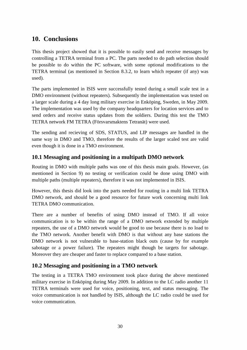
The personnel that were using the LC system during the exercise were very satisfied
with the software (see Figure 10.1 for a screen dump of the software taken during the
exercise, Figure 10.3 shows the use of the hardware). Their opinion was that the update
frequency was sufficient, even when travelling by vehicle. However, if the product was
to be used by the platoon chiefs they would probably have appreciated a bit higher
update frequency.
The soldiers (see Figure 10.2) did not notice the location reports being sent. However,
when (by voice) reporting enemy targets to the company headquarters they found that
giving such reports was much easier when the company headquarters already knew their
position. The only additional information that they needed to report was the distance
and compass direction to the enemy target. They also took the opportunity to send
STATUS messages to the company headquarters (for example, when they are done
securing a building), however most of the time they preferred voice conversation
because of habit.
Based on this I conclude that this technology with my implementation is well suited for
military (and similar) usage. The product needs more work and testing before
production use.
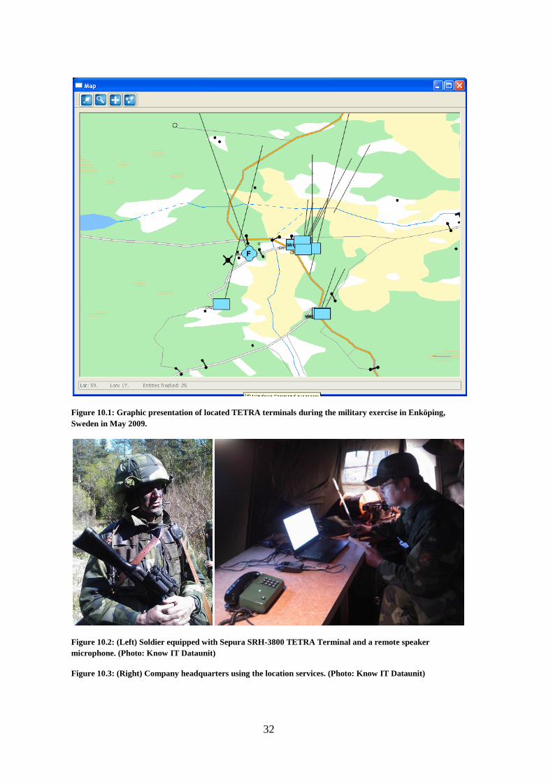
32
Figure 10.1: Graphic presentation of located TETRA terminals during the military exercise in Enköping,
Sweden in May 2009.
Figure 10.2: (Left) Soldier equipped with Sepura SRH-3800 TETRA Terminal and a remote speaker
microphone. (Photo: Know IT Dataunit)
Figure 10.3: (Right) Company headquarters using the location services. (Photo: Know IT Dataunit)

33
11. Future work
It would be interesting to implement or to look into the requirements needed to enable
MSs to create an ad hoc network supporting more than 2 hops. The required
modifications to the standard were earlier investigated by Peter Stavroulakis [20].
An implementation of the software for path selection based on geographical position
should be tested with repeater enabled GPS fitted TETRA terminals. It would also be
interesting to see an extension of this which takes account of environmental effects (due
to trees, differences in heights, and so on).

34
References
1 Swedish Civil Contingencies Agency (MSB). (Last modified 21 April 2008). [www]
http://www.krisberedskapsmyndigheten.se/templates/Page____10820.aspx
Last accessed on 24 March 2009
2 Börje Häll. ISIS Version 3 - Allmän beskrivning. FMV. (2006)
3 John Dunlop, Demessie Girma, and James Irvine. Digital Mobile Communications and the
TETRA System. John Wiley & Sons, (2000). ISBN-10: 0-471-98792-1 and ISBN-13: 978-
0471987925.
4 TETRA MoU Association. About TETRA. (2009). [www]
http://www.tetramou.com/tetramou.aspx?id=44
Last accessed on 24 March 2009
5 ETSI ETS 300 396-1. (1998-03)
6 ETSI EN 300 396-2. (2006-09). V1.3.1
7 ETSI EN 300 396-3. (2006-08). V1.3.1
8 Börje Häll. Interface Requirement Specification for Alfa. FMV. (2007)
9 ETSI EN 300 392-2. (2007-09). V3.2.1
10 ETSI EN 300 396-4. (2006-05). V1.3.1
11 ETSI EN 300 396-7. (2000-12). V1.2.1
12 ETSI TS 100 392-5. (2008-07). V2.1.1
13 ETSI TS 100 392-18-1. (2008-07). V1.4.1
14 Dale DePriest. NMEA data. [www] http://gpsinformation.org/dale/nmea.htm
Last accessed on 30 March 2009
15 Swedish Civil Contingencies Agency (MSB). Utbyggnad och täckning. (Last modified 17
December 2008). [www]
http://www.krisberedskapsmyndigheten.se/templates/Page____117.aspx
Last accessed on 30 March 2009
16 Swedish Civil Contingencies Agency (MSB). Drift- och tjänstespecifikation för
Rakelsystemet. (11 April 2008, Diary number 1199/2006). [PDF]
http://www.krisberedskapsmyndigheten.se/templates/Document____10589.aspx
Last accessed on 30 March 2009
17 H-P A Ketterling. Introduction to Digital Professional Mobile Radio. (2004). ISBN: 1-
58053-173-3.
18 Mikael Nordman, et.al. TETRA radio in Monitoring and Control of Secondary Substations.
In proceedings of the Seventh International Conference on Developments in Power System
Protection, IEE Publication No 479, 2001, pages 283-286.

35
19 D.I. Axiotis and D. Xenikos. On the effects of Short Data Service-Transport Layer
message length in QoS metrics of TETRA networks. In proceedings of IEEE 18th
International Symposium on Personal, Indoor and Mobile Radio Communications
(PIMRC), September 2007, DOI 10.1109/ PIMRC.2007.4394347.
20 Peter Stavroulakis. Terrestrial Trunked Radio – TETRA – A Global Security Tool.
Springer, (2007). ISBN: 978-3-540-71190-2
21 Swedish Civil Contingencies Agency (MSB). Tjänster i Rakelsystemet. (Last modified 16
March 2009). [www]
http://www.krisberedskapsmyndigheten.se/templates/Page____11768.aspx
Last accessed on 20 June 2009
22 Swedish Civil Contingencies Agency (MSB). Nyheter. (Last modified 29 February 2008).
[www] http://www.krisberedskapsmyndigheten.se/templates/Archive____11635.aspx
Last accessed on 20 June 2009
23 B. Karp and H. T. Kung. GPSR: Greedy Perimeter Stateless Routing for Wireless
Networks. MobiCom 2000, AFOSR MURI, NFS. [PDF]
http://www.eecs.harvard.edu/~htk/publication/2000-mobi-karp-kung.pdf
Last accessed on 1 July 2009.
24 F. Granelli, G. Boato, and D. Kliazovich. MORA: a Movement-Based Routing Algorithm
for Vechicle Ad-hoc Networks. SAFESPOT Integrated Project. [PDF]
http://disi.unitn.it/~klezovic/ccount/click.php?id=20
Last accessed on 1 July 2009.
25 H. Menouar, M. Lenardi, and F. Filali. Movement Prediction-Based Routing (MOPR)
Concept for Position-based Routing in Vehicular Networks. In proceedings of IEEE 66th
Vehicular Technology Conference (VETECF), September 2007. DOI
10.1109/VETECF.2007.441
26 D. I. Axiotis, and D. G. Xenikos. On the Performance of TETRA Short Data Service-
Transport Layer. (Springer) Wireless Pers Commun (2007) DOI 10.1007/s11277-007-
9288-x.
27 ETSI TR 101 053-2. (2008-09). V2.2.2
28 D. I. Axiotis, and D. G. Xenikos. UDP Performance Measurements over TETRA IP . In
proceedings of IEEE 65th Vehicluar Technology Conference, 2007 VTC2007-Spring. DOI
10.1109/VETECS.2007.279
29 D. I. Axiotis, and A. K. Salkintzis. Impact of Voice Traffic on the Performance of Packet
Data Transmission in TETRA Networks . IEEE Transactions on Vehicluar Technology,
Volume 57, Issue 5, September 2008, pages 3040 – 3052, DOI 10.1109/TVT.2007.914050

www.kth.se
TRITA-ICT-EX-2009:96


![[MS-SSAS]: SQL Server Analysis Services Protocol SpecificationMS-SSAS]-090801.pdf · SQL Server Analysis Services Protocol Specification ... SQL Server Analysis Services Protocol](https://img.dokumen.tips/doc/110x75/5a849a057f8b9a87368c1cc8/ms-ssas-sql-server-analysis-services-protocol-specification-ms-ssas-090801pdfsql.jpg)