Embed Size (px)
Citation preview

RESEARCH REPORT VTT-R-02440-09
Meshing Tools for Open SourceCFD – A Practical Point of ViewAuthors: Juha Kortelainen
Confidentiality: Public

RESEARCH REPORT VTT-R-02440-09
1 (24)
Report’s titleMeshing Tools for Open Source CFD – A Practical Point of ViewCustomer, contact person, address Order referenceCSC – IT Center for Science Ltd.P.O. Box 405FI-02101 Espoo, Finland
VTT-V-27856-08
Project name Project number/Short nameAvoimen lähdekoodin CFD-esikäsittelytyökalut teollisessakäytössä
27856/LSCFD
Author(s) PagesJuha Kortelainen 24/0Keywords Report identification codeCFD, geometry, gmsh, grid, OpenFOAM, pre-processing,mesh, meshing, SALOME
VTT-R-02440-09
SummaryThis document is part of the project Tools for Large Scale Computational Fluid Dynamics, LSCFD. The projectis managed by CSC – IT Center for Science Ltd. (CSC) and partially funded by Tekes (Finnish Funding Agencyfor Technology and Innovation). The main objective of the project is to promote the use of large scale CFD inFinland. The project will support, enhance and document the use of selected open source CFD solvers. Meshgeneration is an essential part of the solution procedure which often consumes the most of the human resources.
In this report three different tools or utilities for creating a computational mesh for OpenFOAM CFD code arepresented: SALOME, gmsh and OpenFOAM snappyHexMesh. All these software are open source. The point ofview of this study is on practical side, i.e. usability, software ergonomics and ability to produce high quality meshare emphasised instead of meshing algorithms. The same study and test procedure has been applied for all threetools. Software functionality is studied based on soft-ware manuals and by using the software. One common,industrial meshing test case was selected. With this test case the usability of these tools could be tested into someextend and compared. In the last section there is presented some comments about these tools and in general aboutthe development of open source mesh generation tools.
A typical pre-processing (mesh generation) process for CFD or FEM computation is described in general. In thisprocess description the domain geometry is taken as is from the design system (typically CAD system) and all themodifications are done during the pre-processing process.
The study indicates that there are good open source software components already available for CFD pre-processing, but at least the tested implementations haven’t been completely successful in using them and imple-menting a really user friendly, intuitive and industrial strength pre-processing tool. None of the tested tools ormethods can be recommended for general industrial use as such. More development needs to be done for thesemeshing tools to reach a level where the whole process is efficient and produces high quality results. But the de-velopment seems to be on right path and all the elements for good progress are already available.
Confidentiality PublicEspoo 15.4.2009Written by
Juha Kortelainen,Senior Research Scientist
Reviewed by
Tero Kiviniemi,Sales Manager
Accepted by
Pekka Koskinen,Research Manager
VTT’s contact addressVTT Technical Research Centre of Finland, P.O. Box 1000, FI-02044 VTT, FinlandDistribution (customer and VTT)CSC: 2 piecesVTT: 1 piece
The use of the name of the VTT Technical Research Centre of Finland (VTT) in advertising or publication in part ofthis report is only permissible with written authorisation from the VTT Technical Research Centre of Finland.

RESEARCH REPORT VTT-R-02440-09
2 (24)
PrefaceComputational methods are becoming ever more important methods and tools for both indus-trial product development and scientific research. These methods enable fast and cost effec-tive studies of systems and phenomena that often are very difficult and expensive or danger-ous or even impossible to execute. These methods can provide designers and researchers in-formation that helps to understand complex phenomena and thus further develop new and bet-ter products.
In this report one narrow area of applying computation methods has been shortly studied.Spatially discretised methods like finite element method or control volume method are widelyused both in research and product development. To apply these methods to some specificproblems require that the pre-processing tools are available and have the functionality neededfor the specific purpose. This pre-phase of the problem solving is a kind of a mandatory painin the process but still it has remarkable influence on the reliability of the results as well as tofluency of the whole process.I want to thank CSC – IT Center for Science Ltd. (CSC) and LSCFD project for the opportu-nity to do this study and test all these software. I find these tools both very interesting in thearea of computational methods and very important in the whole chain of work phases in com-putation. I hope this work will turn the focus of interest of open source tool developers to thewhole pre-processing chain so that all those great open source computational solvers andother tools would reach the same level in easy-of-use than commercial tools already have.
Espoo 15.4.2009
Juha Kortelainen

RESEARCH REPORT VTT-R-02440-09
3 (24)
Contents
Preface ........................................................................................................................2
Abbreviations and acronyms .......................................................................................4
1 Background ............................................................................................................5
2 Overview of mesh generators.................................................................................52.1 Mesh generation process................................................................................62.2 Test case ........................................................................................................7
3 SALOME.................................................................................................................83.1 Introduction .....................................................................................................83.2 Import/Export capabilities................................................................................93.3 Geometry manipulation capabilities ................................................................93.4 Meshing capabilities........................................................................................93.5 Meshing efficiency ........................................................................................103.6 Mesh generator in action...............................................................................10
3.6.1 Creating the flow channel geometry...................................................103.6.2 Meshing .............................................................................................13
3.7 Short introduction SALOME version 4.1.4.....................................................173.8 Using SALOME with OpenFOAM .................................................................17
4 Gmsh....................................................................................................................184.1 Introduction ...................................................................................................184.2 Geometry capabilities ...................................................................................184.3 Meshing capabilities......................................................................................184.4 Import/Export capabilities..............................................................................194.5 Meshing efficiency ........................................................................................194.6 Mesh generator in action...............................................................................19
4.6.1 Creating the flow channel geometry...................................................194.6.2 Meshing .............................................................................................204.6.3 Using gmsh with OpenFOAM.............................................................20
5 Using OpenFOAM with external meshing tools ....................................................20
6 OpenFOAM snappyHexMesh...............................................................................216.1 Introduction ...................................................................................................216.2 Meshing capabilities......................................................................................216.3 Import/Export capabilities..............................................................................216.4 Meshing efficiency ........................................................................................226.5 Mesh generator in action...............................................................................22
7 Discussion and Conclusions.................................................................................22
References ................................................................................................................24

RESEARCH REPORT VTT-R-02440-09
4 (24)
Abbreviations and acronyms1/2/3D One/two/three dimensional.ACIS 3D solid geometry file format developed by Spatial Corporation.AMR Adaptive mesh refinement; a method to refine mesh based of local solution, e.g. flow ve-
locity gradient.ASCII American standard code for information interchange.BREP Boundary representation; often used method for solid geometry modelling.CAD/CAE Computation aided design/engineering.CFD Computational fluid dynamics.CSG Constructive solid geometry, a method to create complex solid geometries from primitive
geometries using geometric Boolean operations.CVM Control volume method.DAT Abbreviation to data, often used in file name extensions.DXF Drawing Exchange Format, a 3D geometry file format from Autodesk Inc.FEM Finite element method.FOAM Open field operation and manipulation, software library for control volume based compu-
tation; OpenFOAM is an open source version of the software.GHS3D A meshing algorithm developed by team Gamma in INRIA, France.GNU Gnu’s not Unix, GNU open source project’s symbol.GPL GNU general public license.HDF5 Hierarchical data format, version 5; a file format, application programming interface and
routine library for especially scientific data storage.HTML Hyper text markup language, HTML is an SGML application conforming to ISO 8879
standard of Standard Generalized Markup Language (SGML).IGES Initial graphics exchange specification, 3D geometry exchange format and specification.LGPL GNU lesser/library general public license, open source license.LSCFD Large scale computational fluid dynamics, research project’s short name.NASA National aeronautics and space administration.PC Personal computer.Plot3D File format for writing CFD structured grids and solutions; format is developed in NASA.STEP Standard for the Exchange of Product model data, ISO 10303 standard for data exchange.STL Stereolitography, a simple file format to store triangulated surface geometry data.VRML Virtual reality modelling language.VTK Visualization toolkit, open source scientific visualisation library developed by Kitware
Inc.UNV Universal file format, a file format originally developed by Structural Dynamics Research
Corporation (SDRC) for file transfer between CAD and CAE systems.

RESEARCH REPORT VTT-R-02440-09
5 (24)
1 BackgroundThis document is part of the project Tools for Large Scale Computational Fluid Dynamics,LSCFD. The project is managed by CSC – IT Center for Science Ltd. (CSC) and partiallyfunded by Tekes (Finnish Funding Agency for Technology and Innovation). The main objec-tive of the project is to promote the use of large scale CFD in Finland. The project will sup-port, enhance and document the use of selected open source CFD solvers. Mesh generation isan essential part of the solution procedure which often consumes the most of the human re-sources.
This survey is not comprehensible as it will study only a few alternatives in more detail. Thepoint of view of this study is on practical side, i.e. usability, software ergonomics and abilityto produce high quality mesh are emphasised instead of meshing algorithms. In selecting thesoftware open source has not been a necessary condition since also some proprietary meshgenerators are often used with open source solvers. However, a rather inexpensive licensepricing is desirable since typically the users of open source software have limited monetaryresources.For large scale simulations the mesh generation tools must be efficient enough to be able tohandle large meshes interactively on the workstation. For complex geometries the a posterioritechniques of mesh refinement are not satisfactory as the geometry description is different onthe finest level. Therefore it is imperative that large meshes can be created with the chosentools.
2 Overview of mesh generatorsMesh generation is a mandatory process phase in typical CFD, structural and acoustic simula-tions and analyses. Although being just requirement for performing calculation it has an im-portant impact on efficiency and accuracy of computation; element or cell shape and size doesmatter on both computation speed and numerical accuracy. For CVM and in most cases FEM,hexahedron elements are more favourable to numerical efficiency, but there isn’t any generalautomatic and robust mesh generation algorithm available for such a mesh type. Due to in-crease in computational power, the number of elements doesn’t have that much significanceany more. This has lead to use of automated tetrahedral mesh generators both in CVM andFEM. These meshing tools can produce relatively high quality mesh in just tens of seconds orcouple of minutes. The mesh quality is often good enough for structural analysis but in CFDresults are more sensitive on mesh type and quality and the use of tetrahedral mesh can lead toa high number of cells to achieve the same computational accuracy than when using hexahe-dral cells. One solution for the element or cell type issue is the use of a hybrid mesh, i.e. amesh containing both hexahedral and tetrahedral elements or cells. This allows e.g. creationof hexahedral mesh is critical areas manually and mesh the rest of the volume using automaticmesh generation and tetrahedral elements or cells. There are also methods to automaticallycreate hybrid mesh in arbitrary geometry. This area is not covered in this document.In this report three different tools or utilities for creating a computational mesh for Open-FOAM CFD code are presented: SALOME, gmsh and OpenFOAM snappyHexMesh. Allthese software are open source, which mean that the source code of these software is freelyavailable. The same study and test procedure has been applied for all three tools. Softwarefunctionality is studied based on software manuals and by using the software. One common,industrial meshing test case was selected. With this test case the usability of these softwarecould be tested into some extend and compared. In the last section there is presented somecomments about these tools and in general about the development of open source mesh gen-eration tools.

RESEARCH REPORT VTT-R-02440-09
6 (24)
2.1 Mesh generation processComputational meshes are needed in spatially discretised methods like finite element method(FEM), and control volume method (CVM), mostly used for computation fluid dynamics(CFD). In these methods the domain of interest, e.g. a structure or a flow domain, is dividedinto small computational volumes, called elements or cells, which cover the domain so thatthey fill the domain completely but do not overlap on another. Different numerical methodsrequire some specific features from the mesh, e.g. for some methods the mesh has to be struc-tured, meaning the mesh has fixed topological structure through the whole mesh, or the meshelements or cells have to have a specific form like hexahedron. All the special limitationscombined with the shape of the domain itself can set difficult requirements for the meshingprocess and methods used to perform it.In Figure 1 there is illustrated one typical overall meshing process for an industrial applica-tion. In this process description the domain geometry is taken as is from the design system(typically CAD system) and all the modifications are done during the pre-processing process.It is also possible, and often more efficient, to modify the geometry already in the design sys-tem and start the meshing process using more suitable domain geometry.
Design geometryin CAD system
Geometrymanipulation
Design geometry in CFDpre-processing system
Geometryimport
Geometry processing
Simplified and healedgeometry in pre-processing
Meshtopologydesign
Structuredmesh
Unstructuredmesh
Grid density(global/local) Use of AMR
Computational mesh
Final productioncomputational mesh
Mesh processing
Meshing
Figure 1: Ideal work flow for meshing starting from CAD geometry.
The process starts from geometry import to the pre-processing tool. In practice this means im-porting the geometry in a file format that the pre-processing tool supports. There are couple ofneutral formats like STEP (ISO standard) and IGES that most of the design environments,CAD systems and pre-processing tools support. Also some proprietary formats have becomedefacto standards in geometry exchange; an example of these is DXF from Autodesk Inc. Thedifficulty in geometry import is that there are many file formats available and tools supportthese formats in differing level. To find the most usable and robust format between two soft-ware usually requires some testing. Another difficulty is the geometry itself. The same geo-metrical shape can be created using different procedures resulting different geometrical de-

RESEARCH REPORT VTT-R-02440-09
7 (24)
tails. Although the shape may be the same, the geometry may contain small edge and surfaceelements, depending on how the final shape has been processed.The geometry manipulation phase in the process includes typically removal of small irrele-vant details, like chamfers, roundings and small holes. These details may require large amountof computational elements or cells and thus unnecessarily increase the needed computationaleffort. This phase should also include the checking of geometry quality and fixing or removalof geometry representation anomalies, like divided edges with small edge pieces or openseams in surfaces. Depending on the selected meshing algorithm, these may ruin the meshingprocess or lead to poor mesh quality.
In the mesh topology design phase the meshing strategy is decided. Depending on the compu-tational task and used software, the mesh type (structure and unstructured), element or celltype (e.g. tetrahedral or hexahedral) and mesh density (global and local) need to be designed.Also the computational domain splitting into several blocks is often required to have bettercontrol over the mesh quality and to decrease the memory allocation during individual mesh-ing phase. The meshing process is typically iterative in nature; the mesh quality is seen onlyafter the mesh has been created and if some parameters need to be adjusted, the process startsoften from the beginning in the mesh processing phase. In case of using several computationalmesh blocks, there may be procedure iterations inside different mesh blocks.The meshing phase differs substantially depending on the mesh type. Unstructured tetrahedralmesh is usually generated automatically into the given geometry. The user needs to definemeshing parameters like desired element size (mesh density) and optional local mesh ad-justment parameters and meshquality optimisation attributes. Theactual meshing is done by the rou-tine. For structured mesh there areusually several manual processphases. The user defines the blocksfor the mesh; typically there has tobe 12 block edges and six faces thattopologically form a block shape(see Figure 2). Creating a struc-tured mesh for industrial geometryrequires more time and may be adifficult task for complex geome-tries with many geometrical details.Especially for CFD this is often adecision and compromise betweencomputational efficiency, accuracyand the time required for pre-processing.After the mesh has been successfully created the process continues with computation defini-tion, including among others setting boundary conditions and initial conditions for the flowcase. This phase is out of the scope of this report.
2.2 Test caseThe import functionality from a CAD system was tested with realistic design geometry of aWärtsilä W20V34SG exhaust channel model. The geometry was exported form a commercialI-deas CAD software in IGES format. The case geometry is a typical CFD case with complex
Figure 2: A block topology for structured mesh.

RESEARCH REPORT VTT-R-02440-09
8 (24)
geometric features and for CFD use unnecessary details. The original test case geometry isshown in Figure 3.The basic assumption with the test case was that the person responsible of mesh generationgets the geometry from the designer as it is and does to necessary manipulation to the geome-try before meshing. In this case the original geometry is relatively complex related to the re-quirements of the CFD meshing. The case could have been chosen so that the geometry is al-ready manipulated for meshing in the original CAD system (unnecessary features removedand the flow channel modelled as a solid geometry).
Figure 3: Original CAD model.
All the tests were done in a PC workstation running Fedora Linux version 8 and kernel ver-sion 2.6.26.6. The workstation was Dell WS 540 with two Intel Xeon III processors (1.8 GHz)and 1.0 GB of physical memory. The graphics processor was nVidia Quadro4 700 XGL withonly 64 MB of physical memory. The used workstation does not satisfy present requirementsfor a workstation used for CFD or FEM pre-processing in industrial or demanding researchwork. But it is still usable for comparing the differences of the studied pre-processing toolsand running tests with the selected test case.
3 SALOME
3.1 IntroductionSALOME is a general graphical environment for numerical computing using spatially discre-tised, mesh-based methods like finite element or control volume method. The environmentcontains separate working modes for geometry creation or manipulation (Geometry), meshing(Mesh), solver management (Supervisor), post-processor (Post-Pro), and communicationmodule (MED). The software is open source software under GNU Lesser General Public Li-cense (LGPL). The geometry management in the environment is based on Open Cascade ge-ometry kernel and Visualization Toolkit (VTK) visualisation library. The software is availableas binary form for several Linux distributions and in source code. At the time of testing the

RESEARCH REPORT VTT-R-02440-09
9 (24)
software the latest public version was 3.2.6. At the time of writing this report a new version of4.1.4 was published. This section describes the older version 3.2.6 and it’s use for CFD meshgeneration. In section Short introduction SALOME version 4.1.4 the impressions of the newerversion of SALOME are presented.The documentation for end user is somewhat limited and sometimes offers useless informa-tion. All the basic functions are shortly described in a HTML-based document system, butextensive examples, detailed parameter information and description of what operations aremeant to be used for is usually missing. This is quite typical for open source software as thedevelopers know how the software works and thus don’t need the documentation and othersare either not capable of producing documentation or are not motivated to do so.
3.2 Import/Export capabilitiesSALOME supports via Open Cascade the following solid geometry file formats: ACIS, SA-LOME native BREP, IGES, and STEP. Solid geometry can be exported in ACIS, BREP,IGES (version 5.1 and 5.3), and STEP formats. Also STL (both ASCII and binary) can beused as the model export format.Created mesh can be exported from SALOME in DAT, MED, I-deas UNV, and STL format(ASCII or binary). DAT format is general ASCII table which first lists all node point coordi-nates and then elements based on point order. This format enables writing simple converterutilities so that meshes can be used in different applications. MED format is based HDF5 dataformat for mesh and field specific data. Using files with this format have to be written andread using specific I/O library routines. I-deas UNV format is an ASCII format that has anopen format specification. It is design especially for FEM data and is suitable for all meshdata storage. There is a utility for data conversion from UNV format to OpenFOAM internalmesh representation. For more information see section Using OpenFOAM with external mesh-ing tools. The STL format is used for surface mesh export and is not usable for CFD meshexport. At the moment only mesh in UNV format can be used with OpenFOAM.
3.3 Geometry manipulation capabilitiesSALOME has quite extensive capabilities in creation and manipulation of solid geometry.New geometries can be created either using CSG functionality or BREP operations. New sol-ids can be constructed from manipulated existing surface components by adding new surfaceso that a closed volume is produced. SALOME also has good shape healing operations to e.g.find and remove small edge and surface components and to combine surface components.
3.4 Meshing capabilitiesSALOME is capable of producing tetrahedral, hexahedral and prism meshes. For tetrahedralmesh generation there are several options that are described in more detail later in this report.Hexahedral mesh generation requires hierarchical modelling from volume edges and volumefaces to mesh blocks. This can be done also for CAD geometries but is easier for geometriesthat are created in SALOME. In this report hexahedral mesh generation is not presented.Prism meshes are generated by extruding an existing mesh surface to a volume. This methodcan be useful for generating a boundary layer mesh for CFD. Prism mesh generation is alsodiscarded in this report.In SALOME there are quite good control over the mesh topology in general. The mesh can becomposed from sub-meshes which may simplify the meshing and allows larger number ofcells to be produced; this is because the meshing and optimisation algorithms don’t have to
RESEARCH REPORT VTT-R-02440-09
10 (24)
manage the whole set of cells at once. If the generated mesh contains some local anomalies,the user can manually fix this even in cell vertex level. This means the user can define indi-vidual cells by defining corner points (vertices), edges (lines connecting vertices) and finallycells.The generated mesh can be checked for different measures with the controls tools:
Free borders, for edges geometry that belong to one geometry face onlyLength, for geometry edge length checkingBorders at multi-connection, showing how many geometry faces share the same geometryedgeFree edges, for cell edges that belong to one cell face onlyLength 2D, for cell edge length checkingBorders at multi-connection 2D, showing how many cell faces share the same cell edgeArea, for checking cell face areasTaper, for checking the squarness of a face with four cornersAspect ratio, for checking how close cell faces are to the optimal shape of their type (howequal are the lengths of the cell edges)Minimum angle, for checking the minimum angle between to adjacent cell facesWarping angle, for checking the straightness of a quad face (actually constructed of two trian-gles)Skew, for checking the shape of cell facesAspect ratio 3D, same as Aspect ratio above but for cell volumeVolume, for checking cell volumes in the mesh
These measures can be visualised for quickly checking the different quality measures.
3.5 Meshing efficiencyAutomatic mesh generation using tetrahedron elements/cells is relatively fast with both basicmethods (2D surface meshing with either Netgen or Mefisto); the 3D meshing is done usingNetgen meshing routine. Depending on method selection, the meshing operation may requirequite a lot of computer memory. In case the physical memory limit is exceeded in the work-station, the operation becomes extremely slow. To avoid this, the meshing should be startedfrom very coarse mesh and the mesh density should be increased gradually to reach the de-sired mesh density.
3.6 Mesh generator in action
3.6.1 Creating the flow channel geometryIn the SALOME database the solid geometry was represented as one part (see Figure 4). Tobe able to simplify the geometry and to create a negative model (the volume of the flow chan-nel) the manifold inner surface was separated from the original model. To do this, first thesolid geometry was exploded into a solid component and further to geometric faces. OpenCascade routines, used in SALOME, use boundary representation (BREP) method for solidgeometry, thus the solid can be exploded into primitive face components and new or modifiedsolid geometries can be built from these. The operation produced 1049 separate face compo-nents for exhaust manifold.In the test computer the exploded model was very difficult to manage. Even rotating and pan-ning the geometry was difficult and after couple of view operations both zooming and pan-

RESEARCH REPORT VTT-R-02440-09
11 (24)
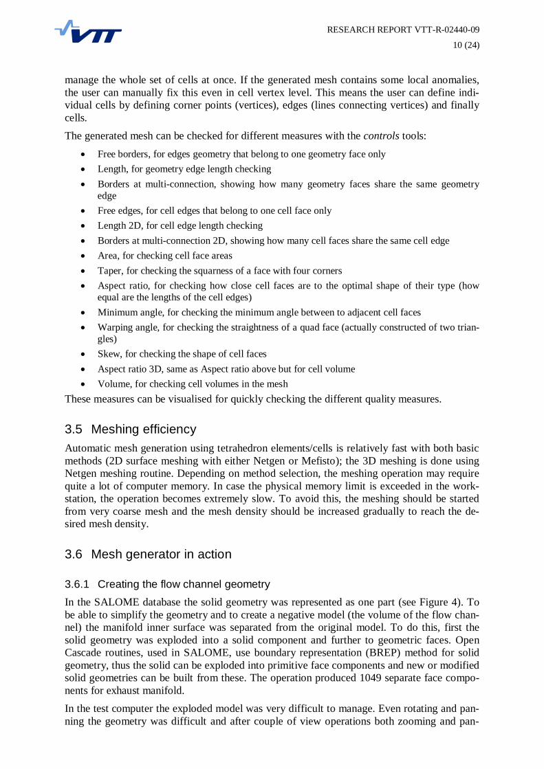
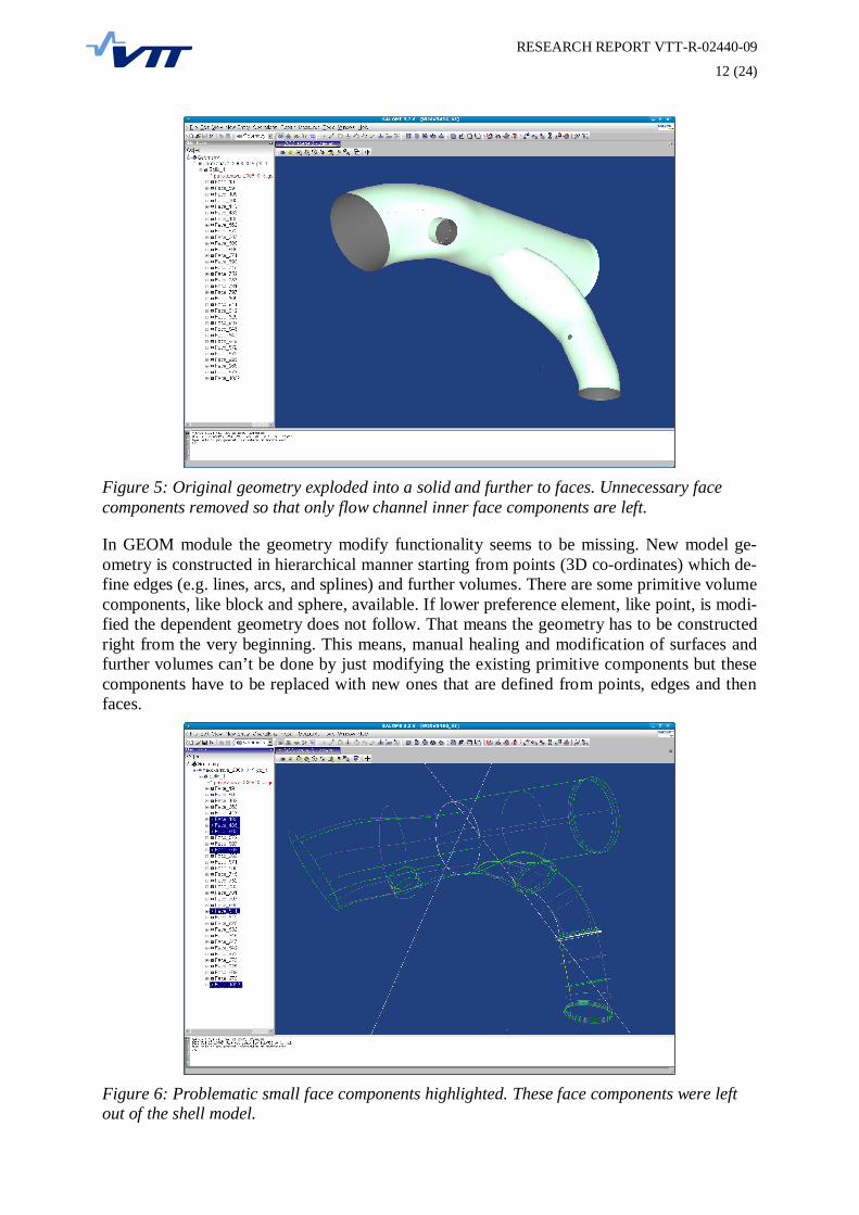
ning hanged. To simplify the manipulation of the geometry, all unnecessary faces were re-moved so that only 33 inner surface components of the original flow channel were left (Figure5). At this phase the geometry was not manifold, but all the channel ends were still open. Themodel contained also small surface components which make it difficult to mesh the final solidvolume. To force SALOME not to use the small faces, they were left out from the next phase,which was building a shell of the face components. The problematic face components arehighlighted in Figure 6.
Building a solid continued first by sewing the gaps in the shell using the sewing function(Figure 7) and then automatically closing the shell using the suppress holes function (Figure8) to produce a volume for solid. The tolerance parameter for sewing had to be figured out bytry and error to close all the gaps. The suppress holes function produced flat surfaces if possi-ble. To ensure that the volume was closed and all the primitive geometric components werevalid a shape processing function was run. This included additional removal of small edgeand face components (Figure 9).The geometry manipulation for CFD meshing in SALOME seems quite straight forward, butthe lack of detailed documentation and difficulties to notice and find small edge and surfacecomponents made the process very time consuming. After learning both the software and thegeometry of the test case the whole process from the original CAD geometry to computationaltetrahedral mesh could be done in just couple of hours. The difficulties in graphics processingand representing made it sometimes frustrating to work with SALOME. But after the learningperiod this tool was found to be very useful, at least for research use. The final flow domainsolid and the original CAD geometry are shown in Figure 10.
Figure 4: The original CAD geometry imported into SALOME in IGES format.
RESEARCH REPORT VTT-R-02440-09
12 (24)
Figure 5: Original geometry exploded into a solid and further to faces. Unnecessary facecomponents removed so that only flow channel inner face components are left.
In GEOM module the geometry modify functionality seems to be missing. New model ge-ometry is constructed in hierarchical manner starting from points (3D co-ordinates) which de-fine edges (e.g. lines, arcs, and splines) and further volumes. There are some primitive volumecomponents, like block and sphere, available. If lower preference element, like point, is modi-fied the dependent geometry does not follow. That means the geometry has to be constructedright from the very beginning. This means, manual healing and modification of surfaces andfurther volumes can’t be done by just modifying the existing primitive components but thesecomponents have to be replaced with new ones that are defined from points, edges and thenfaces.
Figure 6: Problematic small face components highlighted. These face components were leftout of the shell model.

RESEARCH REPORT VTT-R-02440-09
13 (24)
Figure 7: Sewing tool to automatically close small gaps that were introduced when small sur-face components were removed manually.
Figure 8: The suppress holes function was used to automatically close the computational vol-ume for solid creation.
3.6.2 MeshingMeshing in SALOME is done in MESH module (see Figure 11). In principle the meshingprocedure is quite straight forward. First, the solid geometry for meshing is selected from thetree view and then create mesh tool from the tool palette or menu is selected. The create meshpanel contains four tabs: 3D, 2D, 1D and 0D. In each of these tabs first an algorithm formeshing is selected and then based on this a hypothesis for the algorithm. For general geome-try there is an option of assign a set of hypotheses available which automatically set the hy-potheses for e.g. tetrahedron meshing.

RESEARCH REPORT VTT-R-02440-09
14 (24)
Figure 9: The final geometry check and healing using shape processing function.
For unstructured, practically tetrahedral, mesh generation SALOME offers two routines:GHS3D and Netgen. The GHS3D is a commercial meshing routine and thus is not consideredhere. It is also possible to extrude 2D surface mesh as prisms to create e.g. boundary layermesh for CFD. For structured mesh the meshing procedure begins from geometry primitiveslike edges, faces and finally volumes. This procedure is difficult to apply for existing CADgeometries.
There are two procedure paths for meshing with Netgen routine: Netgen 1D-2D-3D whichuses Netgen for all meshing phases, and Tetrahedron (Netgen) which allows using either Net-gen for 1D and 2D meshing or e.g. Mefisto routine for 2D meshing and primitive algorithmsfor 1D meshing.
Figure 10: The used test geometry for one exhaust channel of Wärtsilä W20V34SG diesel en-gine. The original geometry is shown as wireframe graphics and the created flow domain insolid.

RESEARCH REPORT VTT-R-02440-09
15 (24)
Figure 11: Meshing in MESH module using Netgen meshing routine.
For initial meshing of CFD computation Netgen provided simple and robust routine. It waseasier to create a mesh with relatively equal sized elements with Netgen than using manuallydefined meshing algorithms and parameters for 2D and 1D meshing. Meshing with manual2D and 1D routine definition often ended up in low quality mesh that was not suitable forCFD use (Figure 12). Below is described meshing procedure with Netgen routine in more de-tail.
Figure 12: Meshing with manual 2D (Mefisto in this case) and 1D routine definition oftenended up with low quality mesh. In this case there are higher mesh densities in surface com-ponent boundaries and the overall mesh is not relatively equal sized.

RESEARCH REPORT VTT-R-02440-09
16 (24)
Figure 13: Mesh generation result. The whole meshing operation took only couple of minutesthe test system. There were only few parameters that could be adjusted for meshing. The meshis probably more optimized for structural analysis than for CFD; the mesh is relatively densein channel joint corners.
Meshing using Netgen algorithm was slower but didn’t require that much of physical mem-ory. There were only few parameters that could be passed to Netgen routine. E.g. minimumsize of an element couldn’t be defined. Netgen routine seemed to produce small elements inareas of small geometric details, like the joint of the channels. The algorithm could well fol-low small fillets in the joint but the result was a mesh with locally relatively small elements(see Figure 13 and Figure 14). The mesh is most likely more suitable for structural analysisthan for computational fluid dynamics. Now the small elements in joint area are not in thearea of high flow transients. Still these small elements often define the maximum time step forthe CFD computation and thereby ruin the efficiency of the computation.
Creating structural mesh with hexahedral elements is practically impossible for such a com-plex geometry as the one used in this study. Structured mesh can't be created easily from asolid geometry so that all the faces and edges are well discretised. Automatic hexahedralisa-tion would have required lower level geometry components to exist. Also the geometryshould have had suitable topology for meshing.With large geometry models the updating of the visual is very slow causing e.g. the change ofrepresentation from wireframe to shaded take several minutes. This makes it difficult to workfluently when trying to simplify the original CAD geometry to more suitable form for mesh-ing.

RESEARCH REPORT VTT-R-02440-09
17 (24)
Figure 14: Small elements in exhaust manifold channel joint area. These small elements setthe maximum time step for flow computation.
Robustness of the code is in some places low. E.g. manipulating the view can lead into situa-tion where interactive mouse selection is off-set from visual representation. This makes it dif-ficult to work with small geometric components. In some situations the left side database treerepresentations gets corrupted and lots of additional components are presented in the tree. Se-lections between solids and surfaces are not clear and displaying (selecting something to dis-play) may take tens of seconds to update the view. Naturally this is a matter of both graphicsroutines and graphics hardware. Working with a mesh with hundred thousands or even mil-lions elements requires quite powerful graphics hardware to be fluent.
3.7 Short introduction SALOME version 4.1.4At the writing of this report a newer version of open source SALOME software was released.This version 4.1.4 contains numerous bug fixes and enhancements related to the tested ver-sion 3.2.6, including e.g. improvements to slow graphics with large models. There is alsosome new functionality but due to limited resources these have not been tested for this report.[3]
3.8 Using SALOME with OpenFOAMSALOME can be used for mesh generation for OpenFOAM CFD software. OpenFOAM isvery flexible what comes to element/cell shape and topology. Practically any shape of volumeis suitable for OpenFOAM, thus tetrahedral mesh can be used. In general the most suitableelement shape for control volume method would be hexahedron due to its optimal surface andvolume ratio. Also, structural mesh can be more easily created so that the mesh conforms toflow directions which more favourable especially for CVM formulations. But because no gen-eral robust algorithms for automatic hexahedral mesh have been found, and because the over-all process time of computation is critical, tetrahedral mesh is a good compromise.

RESEARCH REPORT VTT-R-02440-09
18 (24)
4 Gmsh
4.1 IntroductionGmsh is an open source modeller and meshing tool for simple geometries. At the website it issaid “its design goal is to provide a simple meshing tool for academic problems with paramet-ric input and advanced visualization capabilities”. In the most resent versions of gmsh supportfor CAD geometries is included using Open Cascade geometry kernel.
4.2 Geometry capabilitiesGmsh has quite limited geometry creation and modification capabilities. New geometry iscreated topologically from primitive components: points, edges, faces, and finally volumes.Open Cascade extension enables use of CAD geometries. Imported CAD geometries can’t bemodified in gmsh. Gmsh can be used together with SALOME via Open Cascade connection.Geometries created with SALOME can be imported into gmsh and further meshed. This ishow gmsh was tested with the test case geometry in this project.
4.3 Meshing capabilitiesLike in SALOME also in gmsh there are different operation modes for different modellingphases. Geometry creation and manipulation is done in Geometry mode and meshing in Mesh-ing mode. There is also Solver and Post-processing modes available for solver interfacing andresults visualisation. The operation mode is selected from the main menu window’s select list(Figure 15). To use an existing CAD geometry, first a model needs to be created using filenew operation. This creates a .geo file to the selected directory. CAD geometry is importedusing merge operation from file menu. Parameters for different operations, like geometrymerge and meshing, are set in option panel.
Figure 15: Gmsh user interface with main menu, options and console windows open.
There are couple of choices for 3D meshing in gmsh, all for tetrahedral mesh. For 2D surfacemeshing options are: Frontal, Delaunay or MeshAdapt+Delaunay. In the tested version ofgmsh Frontal and Delaunay routines are still experimental. Visually comparing Frontal rou-

RESEARCH REPORT VTT-R-02440-09
19 (24)
tine seemed to produce more structured surface mesh than Delaunay routine. In Figure 16 areshown surface meshes with the three different options; other parameters for meshing havebeen the same. For 3D meshing options are: Tetgen+Delaunay or Netgen. Surface meshingwith different routines was in general the same. If the geometry was well formed the meshingparameters were set in option panel and 3D option in mesh mode main menu was selected.Meshing progress and additional information could be seen in console window. The generatedmesh is saved using Save as option from File menu and selecting the appropriate mesh fileformat.
Figure 16: Surface mesh with different meshing routines in gmsh. From left to right: Frontal,Delaunay, and MeshAdapt+Delaunay.
4.4 Import/Export capabilitiesAlthough the software has quite limited geometrical capabilities it can read CAD geometriesin the following format: IGES, STEP, BREP, and naturally gmsh own GEO format. For theCAD geometry information management the system uses Open CASCADE geometry kernel.
Existing meshes can be imported in several formats: I-deas UNV, VTK mesh, MED formats,Medit mesh, Nastran bulk data, Plot3D structured mesh, STL surface mesh, and VRML sur-face mesh. Exporting the mesh is possible in the same formats as import and also in DIFF-PACK 3D mesh format.
4.5 Meshing efficiencyNetgen meshing routine uses Delaunay meshing algorithm for tetrahedral mesh generation.The meshing algorithm implementation requires only modest amount of physical memory andis relatively fast; generation of an unstructured mesh of over 800 000 elements takes onlycouple of minutes. Gmsh has two options for mesh optimisation. This function optimises themesh inner topology so that unnecessary elements are removed. Depending on parameter val-ues and selected method, optimisation can take longer time than initial generation of themesh. Still this operation takes just couple of minutes and is worth using the decrease the sizeof computational model, and thus increasing execution efficiency of the final computation.
4.6 Mesh generator in action
4.6.1 Creating the flow channel geometryGmsh has a strange logic for model creation starting from CAD geometry. First, a new modelneeds to be created and then an existing CAD geometry is merged to the newly created model.Here, the problem is basically in naming the procedures; it would be more intuitive if themerge operation had been named import.Gmsh does not have any geometry manipulation functionality for imported CAD geometries.The only thing that can be done is sewing surface component caps and removing small edge

RESEARCH REPORT VTT-R-02440-09
20 (24)
components using Open Cascade routines. If the geometry is imported in STL format, first thegeometry solid needs to be defined. This operation defines that the given closed volume is thedomain the user wants to mesh. The gmsh meshing routine goes from edges to surfaces andfinally to volume. In case of STL geometry this means the edge and surface meshing is al-ready done (STL is already triangulated representation of the volume surface) and can’t bemodified anymore. Due to this limitation it is practical to import the geometry in some otherformat, e.g. Open Cascade BREP format. This allows more freedom to meshing fine tuning.BREP was used when testing gmsh with the selected test geometry. After the test case geome-try had been imported there wasn’t much to do for it.
4.6.2 MeshingThe meshing process started from defining meshing parameters. Default values were used ex-cept for maximum element size. Also the option for Use incomplete high order elements wasdeselected. After this the meshing was done in phases by selecting in sequence 1D, 2D, and3D from the gmsh main panel.Different gmsh meshing routines were tested with the same input parameter values. Tetgenroutine produced 397 348 elements with given parameters. For the same model and samemeshing parameters Netgen produced only 110 636 elements. Both methods produced fewelements with very high aspect ration (Tetgen: > 3 000, Netgen: > 1.0E+06).The test geometry was meshed with gmsh several times. The meshing algorithm used in gmshdoes the meshing by first discretising surface component edges, then surfaces starting fromedges, and finally volumes starting from surfaces. This approach is sensitive to primitive ge-ometries and the overall quality of the geometry. If surface edges are composed from smallpieces, the meshing can produce extremely small elements in the middle of a simple surface(Figure 17).
Figure 17: Example of small edge component influence on mesh density. Unhealed geometryimported from SALOME to gmsh and meshed using Netgen routine.
4.6.3 Using gmsh with OpenFOAMThere are two ways to use mesh generated with gmsh, either in native gmsh mesh format andusing OpenFOAM gmshToFoam utility or using I-deas UNV format and OpenFOAMIdeasUnvToFoam utility.
5 Using OpenFOAM with external meshing toolsTo convert UNV files, generated e.g. with SALOME or gmsh, to OpenFOAM native meshthe ideasUnvToFoam utility is used. Before using this utility the minimum OpenFOAM casestructure has to be created including the case directory, the system sub-directory and con-trolDict input file. The syntax to run mesh conversion is:
ideasUnvToFoam . Test_01 geometry/test_01.unv

RESEARCH REPORT VTT-R-02440-09
21 (24)
Here the “.” refers to the OpenFOAM case root directory, the next parameter (Test_01) to thecase sub-directory and the last parameter to the input UNV file (in this case under anothersub-directory).
Fot the use of native gmsh mesh files there is a utility in OpenFOAM:
gmshToFoam . Test_01 geometry/test_01.msh
After converting the mesh the of OpenFOAM is in principle as with native OpenFOAMmesh.To automatically find and separate patches in the mesh the autoPatch utility is used. This rou-tine finds edges of the mesh that are sharper than given angle value. The syntax is:
autoPatch . Test_01 60
Here again the first parameter is the OpenFOAM case root directory, the second parameter tothe case sub-directory and the last parameter to patch edge angle.In OpenFOAM version 1.5 case root directory and case directory can be left out if the utilityis run in a sub-directory level. More information how to use OpenFOAM and its utilities canbe found from the user documentation.
6 OpenFOAM snappyHexMesh
6.1 IntroductionOpenFOAM snappyHexMesh method differs from the traditional way of doing pre-processing for CFD. This method uses automatic procedure to create orthogonal hexahedralmesh either around or inside given geometric surface. The surface is given is STL format andcan be generated with a CAD or some other pre-processing tools like SALOME or gmsh. Inprinciple this method enables fast and robust meshing of complex geometries and can be evenused for automated computation procedures. The meshing procedure is described in detail inOpenFOAM User Guide [5].
6.2 Meshing capabilitiesThere are several parameters for mesh creation adjustments. The initial mesh density is set bycreating a block mesh that covers the whole domain. This is the mesh refinement level 0. Therefinement level for the surface area can be set either for whole model or for different surfacecomponents separately. The surface adaptation layer thickness and the maximum allowednon-orthogonality of the snapped surface cells can be set among many other parameters. Theoverall meshing process is sequentially iterative and also the mesh computation parametersneed to be set.
The quality of the mesh can be increased in some cases by using the mesh layer functionality.This offsets the selected surfaces and creates a mesh layer that follows the surface. This is es-pecially useful for computing boundary layer effects like aerodynamic drag or flow separa-tion.
6.3 Import/Export capabilitiesThe geometry for OpenFOAM snappyHexMesh is described either in OpenFOAM’s owntools like blockMesh or by using surface model of the geometry in STL format. Almost allCAD tools can produce STL formatted geometry models. STL is triangulated surface ap-

RESEARCH REPORT VTT-R-02440-09
22 (24)
proximation of the geometry and it contains only information about triangle corner coordi-nates. This makes it very simple to represent any geometry in STL but also looses the infor-mation of the original mathematical surface (e.g. sphere or cylinder).
6.4 Meshing efficiencyDepending on the model size and complexity and if e.g. separate surface mesh is defined, themeshing with snappyHexMesh tools takes from couple of minutes to tens of minutes. Afterthe meshing parameters have been successfully defined, the meshing process is automatic.This is especially practical if different mesh densities are to be tested or used. Because themeshing is not interactive and no graphical tools are used, the creation of large meshes is effi-cient. This enables large computational meshes to be created in a normal workstation PC.
6.5 Mesh generator in actionIn Figure 18 is presented a mesh created for the test case. On left (blue mesh) the core mesh inmesh density level 0 is presented. Clear jagged surface can be seen, thus the shape of individ-ual cells is near optimal (a cube). In the centre (green mesh) the finer refinement level is pre-sented. The mesh is still jagged but can follow the outer surface relatively well. On the right(red mesh) the outer mesh surface is presented. In this layer the outer cells are not anymoreblock shaped but one or several cell surfaces are snapped to geometry surface.
Figure 18: Different mesh refinement levels in the tested case. The coarsest mesh on the left isthe initial mesh defined using the OpenFOAM’s blockMesh utility, the intermediate mesh is inthe centre and the finest surface mesh on the right.
In the present version the recognition of surface edges and corners is still limited and the gen-erated mesh can’t always follow these geometrical features. In some cases this can cause theflow case to be ruined. In Figure 19 can be seen how the meshing algorithm can’t followsharp details the test case geometry. The left side (red surface) is the original STL geometryand the surface on right (in green) is the snappyHexMesh mesh. Edges of the original geome-try are partially chamfered in the mesh.
7 Discussion and ConclusionsIn this work three different open source tools or methods to create computational meshes forCFD, and especially for OpenFOAM software, were studied and tested. Two of these, SA-LOME and gmsh, were independent mesh generation software and the third one was a utilityin OpenFOAM software package. The purpose was to mimic an industrial meshing processstarting from a real-world geometry model in IGES format. With this procedure the processincluded also all the difficulties that a detailed geometry can produce for geometry manipula-tion and meshing. The selected case was found to be very useful for the purpose; the geometrywas apparently simple but still included small geometry details and from meshing point ofview some difficult geometric features.

RESEARCH REPORT VTT-R-02440-09
23 (24)
Figure 19: An example how OpenFOAM snappyHexMesh in the tested version 1.5 can’t al-ways follow sharp edges and corners. On the left in red is the STL geometry and on the rightin green is the meshed geometry.
The SALOME pre-processing software was the most complete package for this purpose. Itincludes quite good functionality for geometry model creation and modifications. The mesh-ing is made relatively simple and in principle it is possible to generate structured hexahedralmesh. In practice the meshing process requires concentration on documentation for both tounderstand the used terminology and all the process phases. And in addition the control overthe meshing of the geometry is not simple. It looked like the software was optimised for FEMmeshing so that geometry edges and small roundings produced really small computationalcells.
Gmsh was very compact package it was quite easy to create computationally good qualitymesh for CFD. The big disadvantage of gmsh is that it does not have geometry manipulationfunctionality for imported CAD geometries, but it can only mesh the imported geometry as is.At the software’s website it is clearly said that to software is focused for academic use. Stillthe software is quite intuitive to use and it can handle also complex geometries.The snappyHexMesh utility in OpenFOAM software package introduces a different but excit-ing method to efficiently create meshes for complex geometries. The learning step with thistool is relatively high, but the step is worth taking. This utility enables also large computa-tional meshes to be created in a normal workstation. The batch kind of working process is es-pecially efficient if the same geometry is needed to remesh with different mesh density ormodified details. The big disadvantage is obviously that the process is not interactive andmany of the definitions need to be learned by try-and-error. Also the geometry model in STLformat has to be generated with some third party programs. Also, the present version of thesnappyHexMesh utility can’t handle well sharp edges and corners. This can be a serious prob-lem in some CFD cases and may prevent using this method for meshing.For fast meshing of complex industrial geometries the best way is either to mix SALOME andgmsh for unstructured tetrahedral mesh or to use OpenFOAM snappyHexMesh, if the geome-try and computation case allows it.

RESEARCH REPORT VTT-R-02440-09
24 (24)
With the tested two interactive pre-processing tools, SALOME and gmsh, one surprising de-fect was found: defining named boundary regions for further use is either not possible or it isdifficult and doesn’t work properly. Named boundary regions mean that the user can definebounded mesh surface areas (sets of cell external surfaces) and give these regions names. E.g.in case the mesh is used with OpenFOAM, named boundary regions remarkably simplifies thedefinition of the flow computation case and allows the case definition without using a visuali-sation tools just to check the boundaries and naming them with some descriptive names.
An industrial meshing process is usually a compromise of mesh quality and the time used formeshing. Regarding this, none of the tested tools or methods can be recommended for generalindustrial use as such. More development needs to be done for these meshing tools to reach alevel where the whole process is efficient and produces high quality results. But the develop-ment seems to be on right path and all the elements for good progress are already available.The study indicates that there are good open source software components already available forCFD pre-processing, but at least the tested implementations haven’t been completely success-ful in using them and implementing a really user friendly, intuitive and industrial strength pre-processing tool. The trend in commercial tools seems to be towards integrated modelling andsimulation environments. The advantage in this approach is that the dataflow between differ-ent tools in the process is fluent. The disadvantage is that some generality is lost because of-ten this approach just ignores the possibility of using just some tools of the software and thechange to a totally different software product. The other approach, in which separate toolsconcentrate only on few tasks but do those tasks well, is usually supported by expert users.The problem especially for beginners and temporary users is the complexity of different toolsinteraction and compatibility of data in different process phases.
References[1] Gmsh website http://www.geuz.org/gmsh/ (December 19, 2008).
[2] SALOME online documentation for version 3.2.6 (December 19, 2008).
[3] SALOME online documentation for version 4.1.4 (December 19, 2008).
[4] SALOME website forum pages http://www.salome-platform.org/forum/ (December 19, 2008).
[5] User Guide. OpenFOAM, version 1.5. 9th July 2008. OpenCFD Limited.
[6] Programmer’s Guide. OpenFOAM, version 1.5. 9th July 2008. OpenCFD Limited.


![Test Drive CFD · 2019. 11. 8. · CFD-Analyse –grundsätzliche Vorgehensweise Aufgabenstellung erfassen und Preprozessing: [SpaceClaim & ANSYS- oder Fluent-Meshing] 1. Ziel der](https://img.dokumen.tips/doc/110x75/60d8c5c9c6a9f4410d421b1b/test-drive-cfd-2019-11-8-cfd-analyse-agrundstzliche-vorgehensweise-aufgabenstellung.jpg)