Embed Size (px)
Citation preview
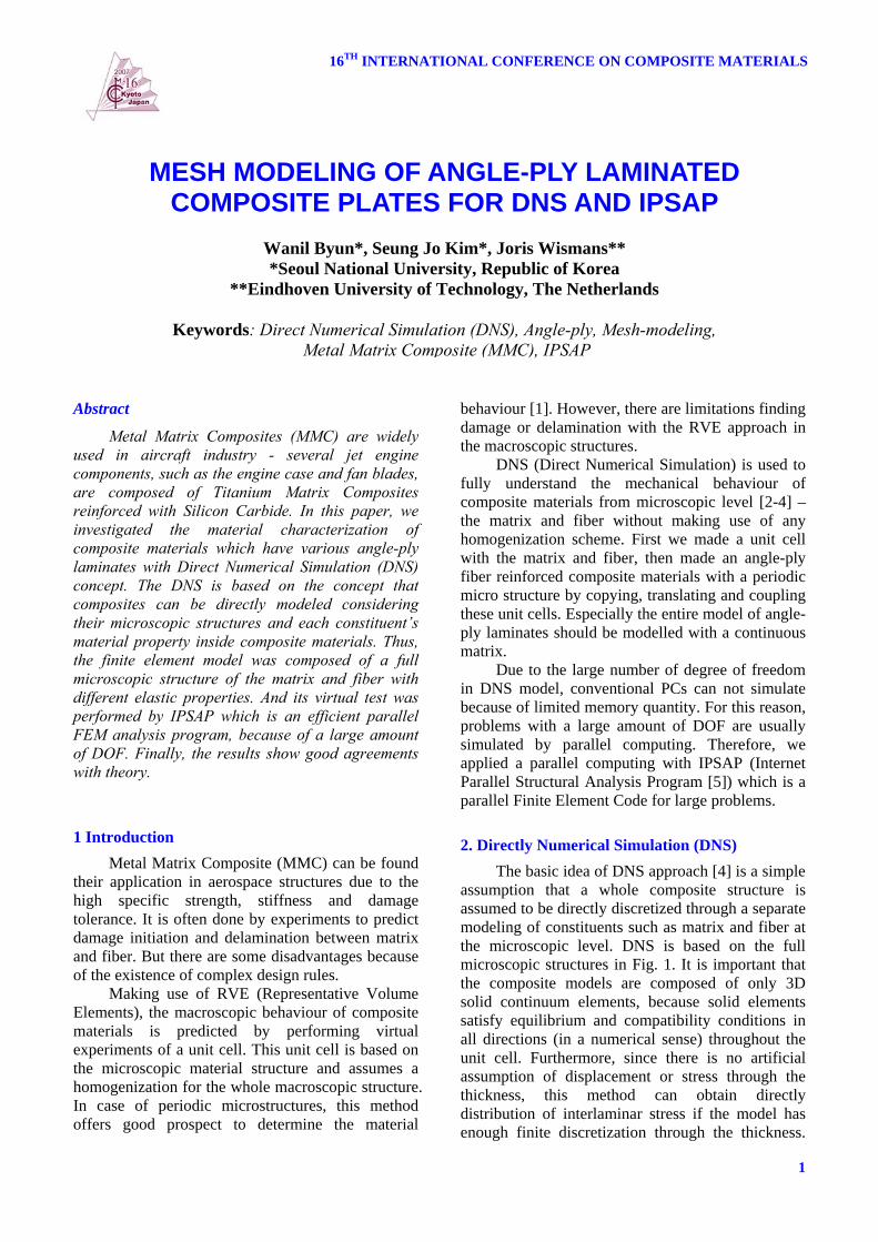
16TH INTERNATIONAL CONFERENCE ON COMPOSITE MATERIALS
1
Abstract
Metal Matrix Composites (MMC) are widely used in aircraft industry - several jet engine components, such as the engine case and fan blades, are composed of Titanium Matrix Composites reinforced with Silicon Carbide. In this paper, we investigated the material characterization of composite materials which have various angle-ply laminates with Direct Numerical Simulation (DNS) concept. The DNS is based on the concept that composites can be directly modeled considering their microscopic structures and each constituent’s material property inside composite materials. Thus, the finite element model was composed of a full microscopic structure of the matrix and fiber with different elastic properties. And its virtual test was performed by IPSAP which is an efficient parallel FEM analysis program, because of a large amount of DOF. Finally, the results show good agreements with theory. 1 Introduction
Metal Matrix Composite (MMC) can be found their application in aerospace structures due to the high specific strength, stiffness and damage tolerance. It is often done by experiments to predict damage initiation and delamination between matrix and fiber. But there are some disadvantages because of the existence of complex design rules.
Making use of RVE (Representative Volume Elements), the macroscopic behaviour of composite materials is predicted by performing virtual experiments of a unit cell. This unit cell is based on the microscopic material structure and assumes a homogenization for the whole macroscopic structure. In case of periodic microstructures, this method offers good prospect to determine the material
behaviour [1]. However, there are limitations finding damage or delamination with the RVE approach in the macroscopic structures.
DNS (Direct Numerical Simulation) is used to fully understand the mechanical behaviour of composite materials from microscopic level [2-4] – the matrix and fiber without making use of any homogenization scheme. First we made a unit cell with the matrix and fiber, then made an angle-ply fiber reinforced composite materials with a periodic micro structure by copying, translating and coupling these unit cells. Especially the entire model of angle-ply laminates should be modelled with a continuous matrix.
Due to the large number of degree of freedom in DNS model, conventional PCs can not simulate because of limited memory quantity. For this reason, problems with a large amount of DOF are usually simulated by parallel computing. Therefore, we applied a parallel computing with IPSAP (Internet Parallel Structural Analysis Program [5]) which is a parallel Finite Element Code for large problems.
2. Directly Numerical Simulation (DNS)
The basic idea of DNS approach [4] is a simple assumption that a whole composite structure is assumed to be directly discretized through a separate modeling of constituents such as matrix and fiber at the microscopic level. DNS is based on the full microscopic structures in Fig. 1. It is important that the composite models are composed of only 3D solid continuum elements, because solid elements satisfy equilibrium and compatibility conditions in all directions (in a numerical sense) throughout the unit cell. Furthermore, since there is no artificial assumption of displacement or stress through the thickness, this method can obtain directly distribution of interlaminar stress if the model has enough finite discretization through the thickness.
MESH MODELING OF ANGLE-PLY LAMINATED COMPOSITE PLATES FOR DNS AND IPSAP
Wanil Byun*, Seung Jo Kim*, Joris Wismans** *Seoul National University, Republic of Korea
**Eindhoven University of Technology, The Netherlands
Keywords: Direct Numerical Simulation (DNS), Angle-ply, Mesh-modeling, Metal Matrix Composite (MMC), IPSAP
WANIL BYUN, Seung Jo Kim, Joris Wismans
2
And DNS model also can obtain a detail 3D stress distribution inside the material as against averaged values from the homogenized model.
Fig. 1. The basic concept of DNS on
composite materials Kim et al [4] showed that the DNS model can
be used to predict effective elastic modulus of the laminates by the virtual numerical simulation such as tensile or shear test. And their results have a good agreement with Sun and Vaidya’s real test result [6].
3. Mesh Modeling In this paper, we modeled three types of MMC
composites. The one is unidirectional composites with s>< °0 lamina and the others are angle-ply composites with s>±< °45 and s>±< °°° 90,45,0 laminates. 3.1 Unidirectional lamina
To model the unidirectional composite plates, the MSC PATRAN program is used for pre-processing procedure. In this case, a volume fraction of 41% is considered to verify with the experimental results [7].
Fig. 2 shows the unit cell of unidirectional lamina. It contains one fiber with a matrix and the finite element is composed of hexagonal elements (8 integration points).
Fig. 2. Unit cell of
unidirectional lamina
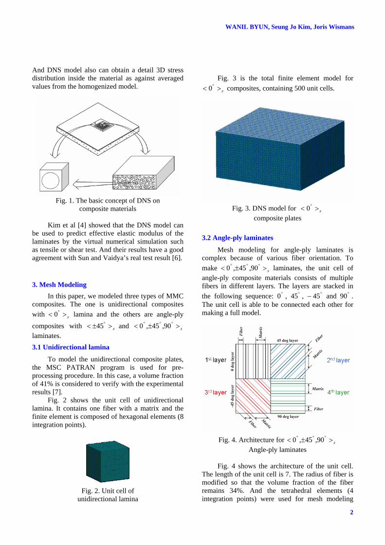
Fig. 3 is the total finite element model for
s>< °0 composites, containing 500 unit cells.
Fig. 3. DNS model for s>< °0
composite plates
3.2 Angle-ply laminates
Mesh modeling for angle-ply laminates is complex because of various fiber orientation. To make s>±< °°° 90,45,0 laminates, the unit cell of angle-ply composite materials consists of multiple fibers in different layers. The layers are stacked in the following sequence: °0 , °45 , °− 45 and °90 . The unit cell is able to be connected each other for making a full model.
Fig. 4. Architecture for s>±< °°° 90,45,0
Angle-ply laminates Fig. 4 shows the architecture of the unit cell.
The length of the unit cell is 7. The radius of fiber is modified so that the volume fraction of the fiber remains 34%. And the tetrahedral elements (4 integration points) were used for mesh modeling
3
MESH MODELING OF ANGLE-PLY LAMINATED COMPOSITE PLATES FOR DNS AND IPSAP
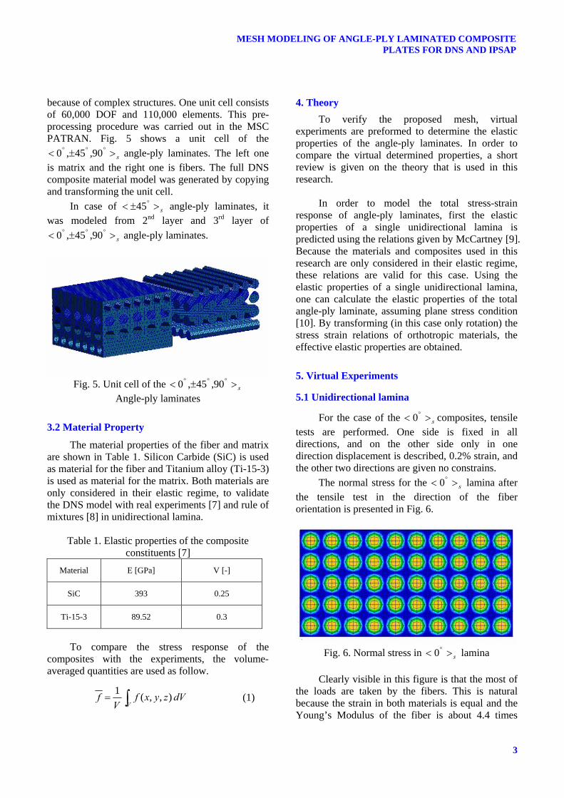
because of complex structures. One unit cell consists of 60,000 DOF and 110,000 elements. This pre-processing procedure was carried out in the MSC PATRAN. Fig. 5 shows a unit cell of the
s>±< °°° 90,45,0 angle-ply laminates. The left one is matrix and the right one is fibers. The full DNS composite material model was generated by copying and transforming the unit cell.
In case of s>±< °45 angle-ply laminates, it was modeled from 2nd layer and 3rd layer of
s>±< °°° 90,45,0 angle-ply laminates.
Fig. 5. Unit cell of the s>±< °°° 90,45,0
Angle-ply laminates
3.2 Material Property
The material properties of the fiber and matrix are shown in Table 1. Silicon Carbide (SiC) is used as material for the fiber and Titanium alloy (Ti-15-3) is used as material for the matrix. Both materials are only considered in their elastic regime, to validate the DNS model with real experiments [7] and rule of mixtures [8] in unidirectional lamina.
Table 1. Elastic properties of the composite
constituents [7] Material E [GPa] V [-]
SiC 393 0.25
Ti-15-3 89.52 0.3
To compare the stress response of the
composites with the experiments, the volume-averaged quantities are used as follow.
∫=V
dVzyxfV
f ),,(1 (1)
4. Theory To verify the proposed mesh, virtual
experiments are preformed to determine the elastic properties of the angle-ply laminates. In order to compare the virtual determined properties, a short review is given on the theory that is used in this research.
In order to model the total stress-strain
response of angle-ply laminates, first the elastic properties of a single unidirectional lamina is predicted using the relations given by McCartney [9]. Because the materials and composites used in this research are only considered in their elastic regime, these relations are valid for this case. Using the elastic properties of a single unidirectional lamina, one can calculate the elastic properties of the total angle-ply laminate, assuming plane stress condition [10]. By transforming (in this case only rotation) the stress strain relations of orthotropic materials, the effective elastic properties are obtained.
5. Virtual Experiments
5.1 Unidirectional lamina
For the case of the s>< °0 composites, tensile tests are performed. One side is fixed in all directions, and on the other side only in one direction displacement is described, 0.2% strain, and the other two directions are given no constrains.
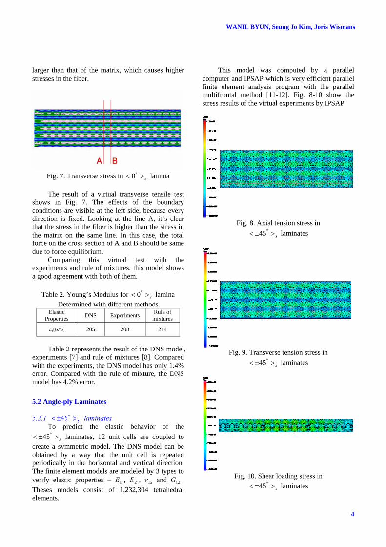
The normal stress for the s>< °0 lamina after the tensile test in the direction of the fiber orientation is presented in Fig. 6.
Fig. 6. Normal stress in s>< °0 lamina
Clearly visible in this figure is that the most of
the loads are taken by the fibers. This is natural because the strain in both materials is equal and the Young’s Modulus of the fiber is about 4.4 times
WANIL BYUN, Seung Jo Kim, Joris Wismans
4
larger than that of the matrix, which causes higher stresses in the fiber.
Fig. 7. Transverse stress in s>< °0 lamina The result of a virtual transverse tensile test
shows in Fig. 7. The effects of the boundary conditions are visible at the left side, because every direction is fixed. Looking at the line A, it’s clear that the stress in the fiber is higher than the stress in the matrix on the same line. In this case, the total force on the cross section of A and B should be same due to force equilibrium.
Comparing this virtual test with the experiments and rule of mixtures, this model shows a good agreement with both of them.
Table 2. Young’s Modulus for s>< °0 lamina
Determined with different methods Elastic
Properties DNS Experiments Rule of mixtures
][1 GPaE 205 208 214
Table 2 represents the result of the DNS model,
experiments [7] and rule of mixtures [8]. Compared with the experiments, the DNS model has only 1.4% error. Compared with the rule of mixture, the DNS model has 4.2% error.
5.2 Angle-ply Laminates
5.2.1 laminates To predict the elastic behavior of the
s>±< °45 laminates, 12 unit cells are coupled to create a symmetric model. The DNS model can be obtained by a way that the unit cell is repeated periodically in the horizontal and vertical direction. The finite element models are modeled by 3 types to verify elastic properties – 1E , 2E , 12ν and 12G . Theses models consist of 1,232,304 tetrahedral elements.
This model was computed by a parallel computer and IPSAP which is very efficient parallel finite element analysis program with the parallel multifrontal method [11-12]. Fig. 8-10 show the stress results of the virtual experiments by IPSAP.
Fig. 8. Axial tension stress in
s>±< °45 laminates
Fig. 9. Transverse tension stress in
s>±< °45 laminates
Fig. 10. Shear loading stress in
s>±< °45 laminates

5
MESH MODELING OF ANGLE-PLY LAMINATED COMPOSITE PLATES FOR DNS AND IPSAP
The elastic properties of the virtual experiments are determined by the relation of the volume average stresses and strains. Table 3 represents the result of the DNS model, Khashaba [13] theory and McCartney theory. Compared with theories, Khashaba’s results have lower errors than McCartney’s.
Table 3. Elastic properties of s>±< °45 angle-ply
laminates with 55.0=fV
DNS Khashaba McCartney
1E [MPa] 14.6 14.2 (2.8%) 14.0 (5.0%)
2E [MPa] 14.6 14.2 (2.8%) 14.0 (5.0%)
12G [MPa] 12.20 12.67 (3.7%) 12.38 (1.4%)
12ν [-] 0.532 0.587 (9.4%) 0.564 (5.7%)
5.2.2 laminates To predict the elastic behavior of the
s>±< °°° 90,45,0 laminates, 12 unit cells are coupled to create a symmetric model. The finite element models are also modeled by 3 types to verify elastic properties – 1E , 2E , 12ν and 12G . Theses models consist of 1,332,628 tetrahedral elements.
This model was also computed by a parallel computer and IPSAP which is very efficient parallel finite element analysis program with the parallel multifrontal method. Fig. 11-13 show the stress results of the virtual experiments by IPSAP.
Fig. 11. Axial tension stress in
s>±< °°° 90,45,0 laminates
The stresses are symmetric around the horizontal middle plane. The stress of matrix is lower and will influence the stress in fiber.
Fig. 12. Transverse tension stress in
s>±< °°° 90,45,0 laminates
Fig. 13. Shear loading stress in
s>±< °°° 90,45,0 laminates
Results of the virtual experiments are shown in Table 4. Beside a virtual axial tensile test for 1E , also a virtual transverse tensile test for 2E and a shear test for 12G are executed. And the theoretical values for the effective elastic properties are also presented in Table 4. These values are caculated with the proposed formulas of McCartney.
Table 4. Elastic properties of s>±< °°° 90,45,0
angle-ply laminates with 34.0=fV
DNS McCartney
1E [MPa] 153 152 (0.6%)
2E [MPa] 153 152 (0.6%)
12G [MPa] 57.63 59.82 (3.6%)
12ν [-] 0.2557 0.2694 (5.1%)

WANIL BYUN, Seung Jo Kim, Joris Wismans
6
6. Conclusion As the results of the DNS about unidirectional
lamina, s>±< °45 and s>±< °°° 90,45,0 laminates, this method is an accurate way to predict the elastic material behavior of composite materials. DNS can be visualized on microscopic level stresses and it shows a good agreement with experimental results. In this paper, we considered only an elastic experiment to verify the capacity of the DNS for angle-ply laminates. In future work, the created meshes could be applied to localize damage initiation in the total model. At last, the DNS requires a large amount of memory, because the finite element model is composed of a full microscopic structure of the matrix and fiber. To solve this problem, the DNS analysis was performed by parallel computing. It can also reduce analysis time.
References [1] E.S. Shin, S.J. Kim “A Thermoviscoplastic Theory
for Composite Materials by Using a Matrix-Partitioned Unmixing-Mixing Scheme”. Journal of Composite Materials, Vol. 30, No. 15, pp 1647-1669, 1996.
[2] K.H. Ji, S.J. Kim “Dynamic Direct Numerical Simulation of Woven Composite For Low-velocity Impact”. Journal of Composite Materials, Vol. 41, No. 2, pp 175-200, 2007
[3] Kuk Hyun Ji “Direct Numerical Simulation on Micromechanical Behaviors of Composite Materials and Structures”. PhD thesis, Seoul National University, 2006.
[4] S.J. Kim, C.S. Lee, H.J. Yeo, J.H. Kim, J.Y. Cho “Direct Numerical Simulations of Composite Structures”. Journal of Composite Materials, Vol. 36, No. 24, pp 2765-2785, 2002.
[5] http://ipsap.snu.ac.kr [6] Sun, C. T. and Vaidya, R. S. “Prediction of
composite properties from a representative volume element”, Composite Science and Technology, Vol. 56, No. 2, pp 171-179, 1996
[7] Bednarcyk, B.A., Arnold, S.M., Lerch, B.A. “Fully Coupled Micro/Macro Deformation, Damage, and Failure Prediction for SiC/Ti-15-3 Laminates”. NASA/TM-2001-211343, 2001.
[8] Jones, R.M. “Mechanics of Composite Materials”. Scripta Book Company, Washington D.C., 1975.
[9] McCartney, L.N., Kelly, A. “Effective thermal and elastic properties of [+θ/-θ]S laminates”. Composites Science and Technology, Vol. 67, No. 3-4, pp 646-661, 2007
[10] Gurdal, Z. “Design and Optimization of Laminated Composite Materials”. John Wiley & Sons, Inc., 1999.
[11] SJ Kim, CS Lee, JH Kim, M Joh, S Lee “IPSAP: A high-performance parallel finite element code for large-scale structural analysis based on domain-wise multifrontal solver”. IEEE/ACM SC2003 Conference, 2003.
[12] Jeong Ho Kim, Chang Sung Lee, Seung Jo Kim “High-Performance Domainwise Parallel Direct Solver for Large-Scale Structural Analysis”. AIAA Journal, Vol. 43, No. 3, pp 662-670, 2005.
[13] U.A. Khashaba “In-plane Shear Properties of Cross-ply Composite Laminates with Different Off-axis Angles”. Composites Structures, Vol. 65, No. 2, pp 167-177, 2004.