Embed Size (px)
Citation preview
DOC 2880 1 Revision 04/08/13
OPERATOR’S MANUAL FOR 10,000 OPM 3 x 4 in. (75 x 100 mm)
ORBITAL SANDERS
Manufacturer/SupplierDIXON ENTERPRISES, INC.571 BIRCH STREET LAKE ELSINORE, CA 92530 Tel: 951-245-4200 Fax: 951-245-4299
Warranty
Please Read and Comply with:
Proper Use of Tool
This sander is designed for sanding all types of materials i.e. metals, wood, stone, plastics, etc. using abrasive designed for this purpose. Do not use this sander for any other purpose than that specified without consulting the manufacturer or the manufacturer’s authorized supplier.
Do not use back-up pads that have a working speed less than 10,000 OPM free speed. Never use back-up pads that have a weight and/or size different than the machine was specifically designed for.
Required Personal Safety Equipment Safety Glasses Breathing Masks
Safety Gloves Ear Protection
Recommended Airline Size - Minimum
10 mm 3/8 in
Recommended Maximum Hose Length
8 meters 25 feet
Air PressureMaximum Working Pressure 6.2 bar 90 psigRecommended Minimum NA NA
Declaration of conformityDIXON ENTERPRISES, INC.
571 BIRCH STREET LAKE ELSINORE, CA 92530declare on our sole responsibility that the products
3 in. x 4 in. 10,000 OPM Orbital Sanders (See “Product Configuration/Specifications” Table for particular Model) to which this declaration relates is in conformity with the following standard(s) or other normative document(s) EN ISO 15744:2008. Following the provisions of
89/392/EEC as amended by 91/368/EEC & 93/44/EEC 93/68/EEC Directives and consolidating Directive 2006/42/EC
Place and date of issue Name Signature or equivalent marking of authorized person
ImportantRead these instructions care-fully before installing, operating, servicing or repairing this tool. Keep these instructions in a safe accessible location.
Original Instructions
Operator InstructionsIncludes – Please Read and Comply, Proper Use of Tool, Warranty, Product Configuration and Specifications Table, Parts Page, Parts List, Work Stations, Putting the Tool Into Service, Operating Instructions and Compressor Layout, Back-Up Pads, Service Tools and Accessories, Overhaul Service Kit, Spare Part Kits, Service Instructions.
1) General Industry Safety & Health Regulations, Part 1910, OSHA 2206, available from: Superintendent of Docu-ments; Government Printing Office; Washington DC 20402
2) Safety Code for Portable Air Tools, ANSI B186.1 available from: American National Standards Institute, Inc.; 1430 Broadway; New York, New York 10018
3) State and Local Regulations.
All SurfPrepTM Orbital Sanders are warranted for defects in materials or workmanship for one year from the date of delivery to the user. Combined with the SurfPrepTM name, this Warranty expresses our total confidence in the superior quality, durability, and performance of the SurfPrepTM LP. To receive any expressed or implied warranty, tool must be repaired by an authorized SurfPrepTM Service Center. The “Service Instructions” section in this document is provided for use after completion of the warranty period. To receive warranty, tools must be operated under the conditions as described in the “Putting the Tools into Service” section of this document and be connected to an air supply system as shown in Figure 1. Tools that have been exposed to extreme conditions will be covered under war-ranty at the sole discretion of SurfPrepTM.
03.22.2013 Meri Faria
DOC 2880 2 Revision 04/08/13
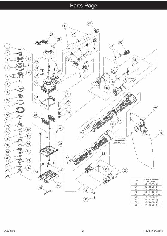
Parts Page
1
2
3
4
7
5
6
8
9
10
11
13
1415
1617
18 19
20 21
2223
24
2728
29
3031
32
33
34
39
40
42 43
44
35
36
37
38
46
47
48
5251
504953
54
5556
57
5859
61
60
6768
70
63
62
64
65
66
45
25
26
TO INLET
TO INLET
TO VACUUMSYSTEM FOR
CENTRAL VAC
76
12
41
71
72
REVISION RECORDR DESCRIPTION / DATE
A-RELEASED FOR PRODUCTION
MCC 03/08/13 FNK 03/08/13
ITEM TORQUE SETTINGNm (in.-lbs.)
12 6.2 - 7.3 (55 - 65)31 2.2 - 2.8 (20 - 25)40 2.8 - 3.4 (25 - 30)42 2.8 - 3.4 (25 - 30)43 10.7 - 11.8 (95 - 105)48 1.8 - 2.3 (16 - 20)52 6.8 - 8.1 (60 -72)56 4.0 - 5.4 (36 - 48)66 3.4 - 3.9 (30 - 35)
XPC0421P/N
TITLE
DRWN BY / DATE
MATERIAL
PROPRIETARY AND CONFIDENTIALTHE INFORMATION CONTAINED IN THIS DRAWING IS THE SOLEPROPERTY OF X'POLE PRECISION TOOLS INC. ANY REPRO-DUCTION IN PART OR AS A WHOLE WITHOUT THE WRITTENPERMISSION OF X'POLE PRECISION TOOLS INC. IS PROHIBITED.
CKD BY / DATE ENG APP / DATE
STD TOL
.X +/-
.XX +/-
.XXX +/-
XX/XX +/-
ANGLES +/-
NANA
NANANA
X'POLE PRECISIONTOOLS INC.
MCC03/08/13 03/08/13
FNK
REVISED 12/19/05
NA
PARTS PAGE FOR SurfPrep™ 3 X 4 in. COMPOSITE OS
DOC 2880 3 Revision 04/08/13
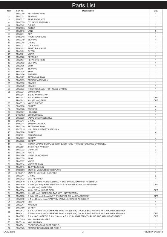
Parts ListItem Part No. Description Qty.
1 SPA0040 RETAINING RING 12 SPA0021 BEARING 13 SPB0017 REAR ENDPLATE 14 SPA0005 CYLINDER ASSEMBLY 15 SPA0042 O-RING 16 SPB0005 ROTOR 17 SPA0010 VANE 58 SPA0041 KEY 19 SPB0016 FRONT ENDPLATE 1
10 SPA0019 BEARING 111 SPA0045 O-RING 112 SPA0001 LOCK RING 113 SPB0102 SHAFT BALANCER 114 SPA0122 FILTER 115 SPA0121 VALVE 116 SPA0120 RETAINER 117 SPA0107 RETAINING RING 118 SPA0162 BEARING 119 SPA0196 SHIM 120 SPA0161 BEARING 121 SPA0108 SHIM 122 SPA0126 WASHER 123 SPA0177 RETAINING RING 124 SPA0163 SPINDLE ASSEMBLY 125 SPA0080 SPACER 126 SPA0079 SPACER 127 SPA2873 THROTTLE LEVER FOR 10,000 OPM OS 128 SPA0031 SPRING PIN 1
29SPA0241 2 ½ in. (65 mm) GRIP 1SPA0242 2 ¾ in. (69 mm) GRIP OPTSPA0243 3 in. (75 mm) GRIP OPT
30 SPA0015 VALVE SLEEVE 131 SPA0768 SCREW 432 SPA0076 WASHER 433 SPA2877 HOUSING 134 SPC0162 SHROUD SEAL 135 SPA0008 VALVE STEM ASSEMBLY 136 SPA0043 O-RING 137 SPB0014 SPEED CONTROL 138 SPA0039 RETAINING RING 139 SPC0018 MINI PAD SUPPORT ASSEMBLY 240 SPA0766 SCREW 441 SPB0101 PAD BACKING 142 SPA0767 SCREW 443 SPA0078 SCREW 144 NA 1 BACK-UP PAD SUPPLIED WITH EACH TOOL (TYPE DETERMINED BY MODEL) 145 SPA0864 2.5mm HEX WRENCH 146 SPA0032 MUFFLER 247 SPA0038 PLATE 148 SPA0166 MUFFLER HOUSING 149 SPA0009 SEAT 150 SPA0007 VALVE 151 SPA0014 VALVE SPRING 152 SPA0013 INLET BUSHING 153 SPB0069 SNAP-IN VACUUM COVER PLATE 154 SPC0017 SNAP-IN EXHAUST ADAPTER 155 SPA0044 O-RING 256 SPA0722 SGV RETAINER 157 SPA0410 Ø 1 in. (28 mm) HOSE SuperVAC™ SGV SWIVEL EXHAUST ASSEMBLY 158 SPA0409 Ø ¾ in. (19 mm) HOSE SuperVAC™ SGV SWIVEL EXHAUST ASSEMBLY OPT59 SPA0778 1 in. (28 mm) HOSE SEAL 160 SPA0854 3/4 in. (28 mm) HOSE SEAL OPT61 SPA0935 1 in. (28 mm) HOSE SEAL TAG WITH INSTRUCTION 162 SPA0298 Ø ¾ in. (19 mm) SuperVAC™ CV SWIVEL EXHAUST ASSEMBLY OPT63 SPA0092 Ø 1 in. (28 mm) SuperVAC™ CV SWIVEL EXHAUST ASSEMBLY 164 SPA0048 NUT 165 SPA0047 WASHER 166 SPA0769 SCREW 1
67SPA0412 Ø 1 in. (28 mm) VACUUM HOSE TO Ø 1 in. (28 mm) DOUBLE BAG FITTING AND AIRLINE ASSEMBLY 1SPA0411 Ø ¾ in (19 mm) VACUUM HOSE TO Ø ¾ in (19 mm) DOUBLE BAG FITTING AND AIRLINE ASSEMBLY OPT
68 SPA0392 Ø 1 in VAC HOSE TO Ø 1 in /28 mm x Ø 1 1/2 in. ADAPTER COUPLING AND AIRLINE ASSEMBLY OPT69 SPC0109 VACUUM BAG INSERT 170 SPC0110 VACUUM BAG 171 SPA2541 FRONT BEARING DUST SHIELD 172 SPA2543 SPINDLE BEARING DUST SHIELD 1
DOC 2880 4 Revision 04/08/13
Specifications subject to change without prior notice.
*The values stated in the table are from laboratory testing in conformity with stated codes and standards and are not sufficient for risk evaluation. Val-ues measured in a particular work place may be higher than the declared values. The actual exposure values and amount of risk or harm experienced to an individual is unique to each situation and depends upon the surrounding environment, the way in which the individual works, the particular mate-rial being worked, work station design as well as upon the exposure time and the physical condition of the user. SurfPrepTM cannot be held responsible for the consequences of using declared values instead of actual exposure values for any individual risk assessment.
Further occupational health and safety information can be obtained from the following websites:
http://europe.osha.eu.int (Europe)
http://www.osha.gov (USA)
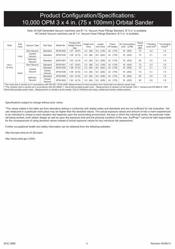
Product Configuration/Specifications:10,000 OPM 3 x 4 in. (75 x 100mm) Orbital Sander
Orbit Pad Face Vacuum Type Pad Type Model No.
Product Net Weight Pound
(kg)
Height inch (mm)
Length inch (mm)
PowerHP (watts)
Air Consumption scfm (LPM)
*Noise Level dBA
**Vibration Level m/s2
**Uncertainty Factor2
1/8 in.(3 mm)
Vinyl
Non-Vacuum Standard SP341000 1.47 (0.67) 3.3 (84) 5.5 (139) .24 (179) 16 (453) 73 3.2 1.6Central Vacuum Standard SP341034 1.58 (0.72) 3.3 (84) 8.0 (202) .24 (179) 16 (453) 72 3.1 1.5
Self-Gen. Vacuum Standard SP341067 1.63 (0.74) 3.3 (84) 8.2 (209) .24 (179) 16 (453) 83 3.5 1.8
Hook
Non-Vacuum Standard SP341001 1.47 (0.67) 3.3 (84) 5.5 (139) .24 (179) 16 (453) 73 3.2 1.6
Central Vacuum
Standard SP341035 1.58 (0.72) 3.3 (84) 8.0 (202) .24 (179) 16 (453) 72 3.1 1.5Screen Vacuum SP341036 1.58 (0.72) 3.3 (84) 8.0 (202) .24 (179) 16 (453) 72 3.1 1.5
Self-Gen. Vacuum
Standard SP341068 1.63 (0.74) 3.3 (84) 8.2 (209) .24 (179) 16 (453) 83 3.5 1.8Screen Vacuum SP341069 1.63 (0.74) 3.3 (84) 8.2 (209) .24 (179) 16 (453) 83 3.5 1.8
*The noise test is carried out in accordance with EN ISO 15744:2008: Measurement of noise emission from hand-held non-electric power tools.**The vibration test is carried out in accordance with EN 28662-1. Hand-held portable power tools – Measurement of vibration at the handle. Part 1: General and EN 8662-8, 1997. Hand-held portable power tools – Measurement of vibration at the handle. Part 8: Polishers and rotary, orbital and random orbital sanders
Note: All Self Generated Vacuum machines use Ø 1 in. Vacuum Hose Fittings Standard. Ø ¾ in. is available.All Central Vacuum machines use Ø 1 in. Vacuum Hose Fittings Standard. Ø ¾ in. is available.

DOC 2880 5 Revision 04/08/13
Work Stations
Putting the Tool into Service
Operating Instructions1) Read all instructions before using this tool. All operators
must be fully trained in its use and aware of these safety rules. All service and repair must be carried out by trained personnel.
2) Make sure the tool is disconnected from the air supply. Select a suitable abrasive and secure it to the back-up pad. Be careful and center the abrasive on the back-up pad.
3) Always wear required safety equipment when using this tool.
4) When sanding always place the tool on the work then start the tool. Always remove the tool from the work before stopping. This will prevent gouging of the work due to excess speed of the abrasive.
5) Always remove the air supply to the sander before fitting, adjusting or removing the abrasive or back-up pad.
6) Always adopt a firm footing and/or position and be aware of torque reaction developed by the sander.
7) Use only correct spare parts.8) Always ensure that the material to be sanded is firmly
fixed to prevent its movement.9) Check hose and fittings regularly for wear. Do not carry
the tool by its hose; always be careful to prevent the tool from being started when carrying the tool with the air supply connected.
The tool is intended to be operated as a hand held tool. It is always recommended that the tool be used when standing on a solid floor. It can be in any position but before any such use, the operator must be in a secure position having a firm grip and footing and be aware that the sander can develop a torque reaction. See the section “Operating Instructions”.
Use a clean lubricated air supply that will give a measured air pressure at the tool of 90 psig (6.2 bar) when the tool is running with the lever fully depressed. It is recommended to use an approved 3/8 in. (10 mm) x 25 ft (8 m) maximum length airline. It is recommended that the tool be connected to the air supply as shown in Figure 1.Do not connect the tool to the airline system without incorpo-rating an easy to reach and operate air shut off valve. The air supply should be lubricated. It is strongly recommended that an air filter, regulator and lubricator (FRL) be used as shown in Figure 1 as this will supply clean, lubricated air at the correct pressure to the tool. Details of such equipment can be obtained from your supplier. If such equipment is not used then the tool should be manually lubricatedTo manually lubricate the tool, disconnect the airline and put 2 to 3 drops of suitable pneumatic motor lubricating oil such as Fuji Kosan FK-20, Mobil ALMO 525 or Shell TORCULA® 32 into the hose end (inlet) of the machine. Reconnect tool to the air supply and run tool slowly for a few seconds to allow air to circulate the oil. If the tool is used frequently, lubricate it on a daily basis or lubricate it if the tool starts to slow or lose power.It is recommended that the air pressure at the tool be 90 PSI (6.2 Bar) while the tool is running so the maximum RPM is not exceeded. The tool can be run at lower pressures but should never be run higher than 90 PSI (6.2 Bar). If run at lower pres-sure the performance of the tool is reduced.
10) Dust can be highly combustible. Vacuum dust collection bag should be cleaned or replaced daily. Cleaning or replacing of bag also assures optimum performance.
11) Do not exceed maximum recommended air pressure. Use safety equipment as recommended.
12) The tool is not electrically insulated. Do not use where there is a possibility of coming into contact with live electricity, gas pipes, water pipes, etc. Check the area of operation before operation.
13) Take care to avoid entanglement with the moving parts of the tool with clothing, ties, hair, cleaning rags, etc. If entangled, it will cause the body to be pulled towards the work and moving parts of the machine and can be very dangerous.
14) Keep hands clear of the spinning pad during use.15) If the tool appears to malfunction, remove from use im-
mediately and arrange for service and repair.16) Do not allow the tool to free speed without taking pre-
cautions to protect any persons or objects from the loss of the abrasive or pad.
Closed Loop Pipe SystemSloped in the direction of air flow
Drain Leg
Ball Valve
To Tool Station
Filter
Drain Valve
Regulator
Lubricator
BallValve
Ball Valve Air Flow
Air Dryer
Air Compressorand Tank
Air Hose
To Couplerat or near Tool
Figure 1

DOC 2880 6 Revision 04/08/13
Overhaul Service Kit for 10,000 OPM 3x4 in. OS ContentsPart No. Description Qty.
SPA0040 External Retaining Ring 1SPA0021 Bearing 1SPA0042 O-Ring 1SPB0005 Rotor 1SPA0010 Vane 5SPA0041 Key 1SPA0019 Bearing 1SPA0162 Bearing 1SPA0196 Shim 1SPA0161 Bearing 1SPA0008 Valve Stem Assembly 1SPA0043 O-Ring 1SPA0039 Internal Retaining Ring 1SPC0018 Mini Pad Support Assembly 2SPA0032 Muffler 2SPA0166 Muffler Housing 1SPA0009 Seat 1SPA0007 Valve 1SPA0014 Valve Spring 1
Overhaul Service KitThe SPA0311 Overhaul Service Kit contains all the replacement parts that naturally wear over time and a straightforward manual to make servicing an SurfPrepTM sander simple. Overhauling the Orbital Sander can be made even easier with the use of the above Service Tools. The Service Tools also reduce the chance of improper assembly.
Service Tools and Accessories
T-6 MOTOR LOCK RING WRENCH/SPINDLE PULLER
T-7 SOFT COLLAR T-8 MOTOR FACE PLATEBEARING REMOVAL TOOL
T-13 BEARING PRESS TOOL
T-9 BEARING PULLER
T-1 BEARING PRESS TOOLS
T-12 5/16 - 24 to M6 x 1P ADAPTER ASSEMBLY
T-2 OS SPINDLE BEARING PRESS TOOLS
When an SurfPrepTM Low Profile Orbital Sander needs to be serviced, we offer tool kits to make the disassembly/assembly fast and easy. The Service Tools are highly recommended for use with the Overhaul Service Kit. The Universal Tool Kit will work with all current models. NOTICE: To receive any expressed or implied warranty, the tool must be repaired by an authorized SurfPrepTM Service Center. The 3 in. x 4 in. Orbital Sander Service Instructions section provided below is for use after completion of the warranty period.
SERVICE INSTRUCTIONS FOR 10,000 OPM
3 x 4 in. (75 x 100 mm) ORBITAL SANDERS
SPA0479 UNIVERSAL SERVICE TOOL KIT SPA0484 3 in. x 4 in. SERVICE TOOL KIT
DOC 2880 7 Revision 04/08/13
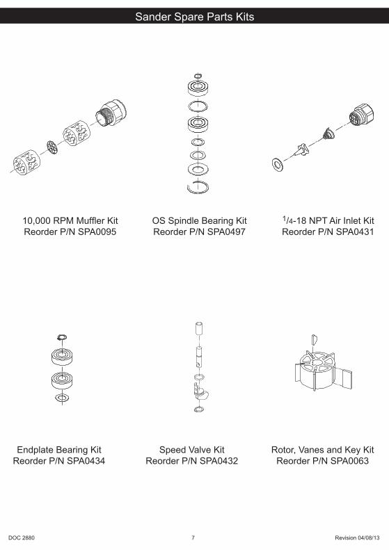
1/4-18 NPT Air Inlet KitReorder P/N SPA0431
10,000 RPM Muffler KitReorder P/N SPA0095
OS Spindle Bearing KitReorder P/N SPA0497
Sander Spare Parts Kits
Endplate Bearing KitReorder P/N SPA0434
Speed Valve KitReorder P/N SPA0432
Rotor, Vanes and Key KitReorder P/N SPA0063
Scaled 50%
Scaled 50%
Scaled 50%Scaled 50%
Scaled 50%
Scaled 50%

DOC 2880 8 Revision 04/08/13
DISASSEMBLY INSTRUCTIONSChanging Grips:1. The Grip has two “tabs” that wrap around the body of the
sander under the inlet and exhaust. With a small screwdriver pick out one of the “tabs” of the Grip, and then continue to go underneath the grip with the screwdriver and pry the Grip off the sander. To install a new Grip, hold the Grip by the tabs making them face outward, align the Grip and slide it under the Throttle Lever then press the Grip down until it seats onto the top of the sander. Make sure the two “tabs” seat under the inlet and exhaust.
Motor Disassembly:1. Remove the Pad from the machine by removing the four
Screws. Lightly secure tool in a vise using the T-7 Soft Collar or padded jaws with the bottom of the machine facing up-ward. Remove the four Screws and then the Screw. Remove the Pad Backing but be careful to observe and collect the optional Spacer(s) found between the Spindle Assembly and the Pad Backing.
2. Take the machine out of the vise and take off the Soft Collar. Remove the four Screws with the Washers from the Housing and remove the Mini Pad Supports. Lightly re-secure the tool in a vise using the T-7 Soft Collar or padded jaws with the Lock Ring facing upward.
3. Remove the Lock Ring with the T-6 Motor Lock Ring Wrench/Spindle Puller Tool. Remove the O-Ring from the Lock Ring and set it aside. The motor assembly can now be lifted out of the Housing.
4. Remove the Retaining Ring from the groove in the Shaft Balancer and the O-Ring from the Cylinder.
5. Remove the Rear Endplate. This may require setting the Rear Endplate on a Bearing Separator and lightly pressing the shaft through the Bearing and Rear Endplate. Remove the Cylinder and the Rotor with the five Vanes from the Shaft Balancer. Remove the Key then press off the Front Endplate with the Bearing. It may be necessary to remove the Bearing with a Bearing Separator if it came out of the Front Endplate and stuck to the shaft of the Shaft Balancer.
6. Remove and discard Dust Shield from the Shaft Balancer.7. Remove the Bearing(s) from the Endplates by using the T-8
Bearing Removal Tool to press out the Bearings.
Shaft Balancer and Spindle Disassembly:1. Grip the shaft end of the Shaft Balancer in a padded vise.
With a thin screwdriver pick out the slotted end of the Retain-ing Ring and peel out.
2. Screw the female end of the T-12 5/16-24 to M6 x 1P Adapter into the male end of the T-6 Motor Lock Ring Wrench/Spindle Puller Tool. Screw the Service Wrench Assembly into the Spindle Assembly until hand tight. Apply a gentle heat from a propane torch or hot air gun to the large end of the Shaft Balancer shaft until it is about 100° C (212° F) to soften the adhesive. Do not over heat. Remove the Spindle Assem-bly by using the slider to give sharp outward blows to the Spindle. Allow the Spindle and Shaft Balancer to cool.
3. Remove the Retaining Ring from the Spindle Assembly. Use a Bearing Separator to remove the Bearing, Shim, Bearing, Shim, Dust Shield and the Washer from the Spindle Assem-bly. Discard Dust Shield.
4. The AirSHIELD™ components are held in place by the light press fit of the Retainer. These components can be damaged during removal and may need to be replaced if removed. To remove the Retainer, use an O-ring pick or a #8 sheet metal screw to grip and pull out the Retainer. Remove the Valve and Filter from the bore in the Shaft Balancer. If the Retainer and Valve were not damaged, they can be reused. However, the filter should be replaced on re-assembly.
Housing Disassembly:1. For Non-Vacuum (NV) and Central Vacuum (CV) machines
follow steps A – C below (unless otherwise noted). For Self Generated Vacuum (SGV) machines disregard steps A – F and move onto Step G below.
A. Unscrew the Muffler Housing from the Housing.B. Remove the Muffler from the cavity of the Muffler Housing.C. Remove the Plate and second Muffler from the exhaust port
of the Housing.For Central Vacuum (CV) Exhaust machines:D. Remove the Screw, Washer and Nut.E. Press downward on the swivel end of the Ø 1 in. (28 mm)
SuperVAC™ CV Swivel Exhaust Assembly or the Ø ¾ in. (19 mm) SuperVAC™ CV Swivel Exhaust Assembly releasing the tab on the end of the exhaust assembly from the Snap-In Exhaust Adapter.
F. Work off the Snap-In Exhaust Adapter. Move on to step 2.
For Self Generated Vacuum (SGV) Exhaust machines:G. Unscrew the SGV Retainer Assembly with an 8 mm hex key.
Remove the two O-rings. Take off the Ø 1 in. (28 mm) SGV Swivel Exhaust Assembly or the Ø ¾ in. (19 mm) Hose SGV Swivel Exhaust Assembly.
H. Work off the Snap-In Exhaust Adapter.2. Place the Speed Control to the midway position and remove
the Retaining Ring. The Speed Control will now pull straight out. Remove the O-Ring.
3. Unscrew the Inlet Bushing Assembly from the Housing. Remove the Valve Spring, Valve, Valve Seat, Valve Stem with the O-Ring. Press out the Spring Pin from the Housing and remove the Lever.
ASSEMBLY INSTRUCTIONSNOTE: All assembly must be done with clean dry parts and all bearings are to be pressed in place by the correct tools and procedures as outlined by the bearing manufacturers.
Housing Assembly:1. Install the Throttle Lever into Housing with the Pin.2. Lightly grease O-Ring and place it on Speed Control. Install
Valve Stem, O-Ring (cleaned and lightly greased) and insert the Speed Control into Housing in the midway position. Install Retaining Ring.
CAUTION: Make sure the Retaining Ring is completely snapped into groove in the Housing.3. Install the Valve Seat, the Valve and Valve Spring. Coat the
threads of the Bushing Assembly with 1 or 2 drops of Loc-tite™ 222 or equivalent non-permanent pipe thread sealant. Screw the assembly into the Housing. See the “Parts Page” for torque settings. Place a clean Muffler and Plate into the exhaust port of the Housing. Be careful not to lose the Plate and Muffler out of the exhaust before it is secured in one of the following steps.
NOTE: If the machine is a CV/SGV model proceed with the appropriate vacuum exhaust assembly instructions, otherwise move onto step 4.
For CV (Central Vacuum) Exhaust machines:A. Attach the Snap-In Exhaust Adapter.B. Take the Ø 1 in. (28 mm) SuperVAC™ CV Swivel Exhaust
Assembly or the Ø ¾ in. (19 mm) SuperVAC™ CV Swivel Exhaust Assembly and put the “tongue” on the male end of it into the female end of the Snap-In Exhaust Adapter. With the swivel end of the SuperVAC™ Exhaust angled towards the ground work the “tongue” and male end into the female end of the Snap-In Exhaust Adapter by rotating the swivel end up and in at the same time until it seats.
C. Thread the Screw into the mounting hole of the Ø 1 in. (28 mm) SuperVAC™ CV Swivel Exhaust Assembly or the Ø ¾
NOTICE: To receive any expressed or implied warranty, the tool must be repaired by an authorized Service Center. The 3 in. x 4 in. Orbital Sander Service Instructions section provided is for use after completion of the warranty period.
3 in. x 4 in. (75 x 100 mm) Orbital Sanders Service Instructions

DOC 2880 9 Revision 04/08/13
in. (19 mm) SuperVAC™ CV Swivel Exhaust Assembly and Housing until the end of it is flush with the inside surface of the Housing. Place the washer and Nut into the cavity of the Housing and thread the Screw into them until tight. Move onto step 4.
For SGV (Self Generated Vacuum) Exhaust machines:A. Attach the Snap-In Exhaust Adapter.B. Lightly grease two O-rings and place them over the two
grooves in the SGV Retainer Assembly. Slide the SGV Retainer Assembly into the bore of the Ø 1 in. (28 mm) SGV Swivel Exhaust Assembly or the Ø ¾ in. (19 mm) Hose SGV Swivel Exhaust Assembly.
C. Attach the SGV Swivel Exhaust Assembly to the exhaust port of the Housing by means of the SGV Retainer Assembly and by taking the male end of the SGV Swivel Exhaust Assembly and placing it into the female end of the Snap-In Exhaust Adapter. Screw the SGV Retainer Assembly into the threaded exhaust port on the Housing with an 8 mm hex key. See the “Parts Page” for torque settings. Move onto the section “Spindle, AirSHIELD™ and Balancer Shaft Assembly”.
4. Place a clean Muffler in the Muffler Housing and screw the Muffler Housing into the exhaust port of the Housing. See the “Parts Page” for torque settings.
Spindle, AirSHIELD™ and Balancer Shaft Assembly:1. Place the T-2A Spindle Bearing Pressing Tool Base onto a
flat, clean surface of a small hand press or equivalent with the spindle pocket facing upward. Place the Spindle into the spindle pocket with the shaft facing upward.
2. Place the Washer on the Spindle shaft with the curve of washer facing out so that the outside diameter of the washer will contact the outer diameter of the Bearing. Place the Dust Shield onto the Spindle shaft. Lay the Shim on the shoulder of the Spindle. Note: Be sure that the Dust Shield is past the shoulder where Spacer rests. Place the Bearing (one seal) on the Spindle with the seal side toward the Washer. NOTE: Make sure that both the inner and outer races of the Bearings are supported by the Bearing Press Tool when pressing them into place. Press the Bearing onto the shoulder of Spindle using the T-2B Spindle Bearing Pressing Tool Top as shown in Figure 3.
3. Place the Shim over the Spindle shaft and onto the face of the Bearing making sure it is on center. Press the (no seals/shields) Bearing down using the T-2B Spindle Bearing Pressing Tool Top, being careful to make sure the Shim is still centered on the vertical axis of the Spindle shaft and Bearing. See Figure 4. When the Spindle Assembly is done correctly, the Bearings will rotate freely but not loosely and the Shim
can be moved but will not slide or move by gravity.4. Snap the Retaining Ring (not shown in Figure 3 or 4) onto the
Spindle Assembly making sure it is completely snapped into the groove.
5. Take the Filter and center it on the small bore that the original Filter was in before removal. With a small diameter screw-driver or flat-ended rod, press the Filter into the bore until it is flat in the bottom of the bore. Place the Valve into the bore so it is oriented correctly, then press the Retainer into the bore until it is flush with the bottom of the Bearing bore.
6. Apply a pin head size drop of #271 Loctite® or equivalent to the outside diameter of each of the bearings on the spindle assembly. Spread the drop of bearing locker around the bearings until distributed evenly. CAUTION: Only a very small amount of bearing locker is needed to prevent rotation of the bearing OD. Any excess will make future removal difficult. Place the Spindle Assembly into the bore of the Shaft Bal-ancer and secure with the Retaining Ring. CAUTION: Make sure that the Retaining Ring is completely snapped into the groove in the Balancer shaft. Allow the adhesive to cure.
Motor Assembly:1. Place the Dust Shield onto the shaft of the Shaft Balancer. 2. Use the larger end of the T-13 Bearing Press Sleeve to
Press the front Bearing (with 2 Shields) onto the shaft of the Shaft Balancer.
3. Slide the Front Endplate with the bearing pocket facing down onto the Motor Shaft. Gently press the Front Endplate onto the front Bearing using the larger end of the T-13 Bearing Press Sleeve until the front Bearing is seated in the bearing pocket of the Front Endplate. CAUTION: Only press just enough to seat the Bearing into the pocket. Over-pressing can damage the Bearing.
4. Place the Key into the groove on the Shaft Balancer. Place the Rotor on the Shaft Balancer, making sure that it is a tight slip fit.
5. Oil the Vanes with a quality pneumatic tool oil and place them in the slots in the Rotor. Place the Cylinder Assembly over the Rotor with the short end of the Spring Pin engaging the blind hole in the Front Endplate. NOTE: The Spring Pin must project .060 in. (1.5 mm) above the flanged side of the Cylinder.
6. Press fit the rear Bearing (2 shields) into the Rear Endplate with the T-1B Bearing Press Tool Top. Make sure the T-1B Press Tool is centered on the O.D. of the outer race. Lightly press fit the Rear Endplate and Bearing over the Shaft Balancer using the small end of the T-13 Bearing Press Sleeve. The sleeve should press only the inner race of the bearing. IMPORTANT: The Rear Endplate and Bearing is
Press Tool Top
Press Tool Base
Figure 2 Figure 4
Bearing
Shim
Bearing
Washer
Spindle
Figure 3
Shim
Dust shield
DOC 2880 10 Revision 04/08/13
pressed correctly when the Cylinder is squeezed just enough between the Endplates to stop it from moving freely under its own weight when the shaft is held horizontal, but be able to slide between the Endplates with a very light force. If the assembly is pressed to tightly the motor will not run freely. If the pressed assembly is to loose, the motor will not turn freely after assembly in the Housing. CAUTION: If the Rear Endplate assembly is “over-pressed” damage to the Front and Rear Endplate Bearings may result.
7. Secure the assembly by placing the Retaining Ring in the groove of the Shaft Balancer. CAUTION: The Retaining Ring must be placed so that the middle and two ends of the hoop touch the Bearing first. Both raised center portions must be securely “snapped” into the groove in the Shaft Balancer by pushing on the curved portions with a small screwdriver.
8. Lightly grease the O-Ring and place in the air inlet of the Cylinder Assembly.
9. Lightly grease or oil the inside diameter of the Housing, line up the Spring Pin with the marking on the Housing and slide the Motor Assembly into the Housing. Make sure the Pin engages the pocket in Housing.
10. Carefully screw the Lock Ring into the Housing with the T-6 Motor Lock Ring Wrench/Spindle Puller Tool. See the “Parts Page” for torque settings. NOTE: A simple technique to as-sure first thread engagement is to turn the lock ring counter clockwise with the T-6 Motor Lock Ring Wrench/Spindle Puller while applying light pressure. You will hear and feel a click when the lead thread of the lock ring drops into the lead thread of the housing.
11. Place one of the Mini Pad Support Assemblies into the Housing with the 45 degree chamfer of the base facing outward away from the center of the machine and the arc in the base of the pad support facing toward the center of the machine. Screw tight with the two Screws and Washers. Repeat for second pad support.
12. Using a straight edge placed across both bottom surfaces of the Mini Pad Support Assemblies, measure the distance from the surface of the Spindle Assembly to the straight edge. There should be approximately .010 in. (0.25 mm) of space, if not add supplied Spacers in the combination that most closely results in .010 in. (0.25 mm) of spacing. NOTE: Spindle face must be slightly below Mini Pad Supports for best function. Do not over shim. Apply a small amount of anti-seize compound in the 5-90° c’sink holes of the Pad Backing before assembly. Place the Pad Backing by orien-tating the Shims with the screw holes and placing the pad backing down onto the Spindle Assembly making sure the Pin goes through the Pad Backing. Add the Screw first and tighten firmly. In a circular rotation apply smaller Screws into the Pad Backing and Mini Pad Support Assemblies but leave them slightly loose until all are in place, and then tighten firmly.
13. Attach a new Pad on the Pad Backing with the four Screws.
Testing:Place 3 drops of quality pneumatic air tool oil directly into the motor inlet and connect it to a 90 psig (6.2 Bar) air supply. The tool should run between 9,500 and 10,500 Orbits per Minute when the air pressure is 90 psig (6.2 Bar) at the inlet of the tool while the tool is running at free speed.
* Loctite® is a registered trademark of the Loctite Corp.
DOC 2880 11 Revision 04/08/13
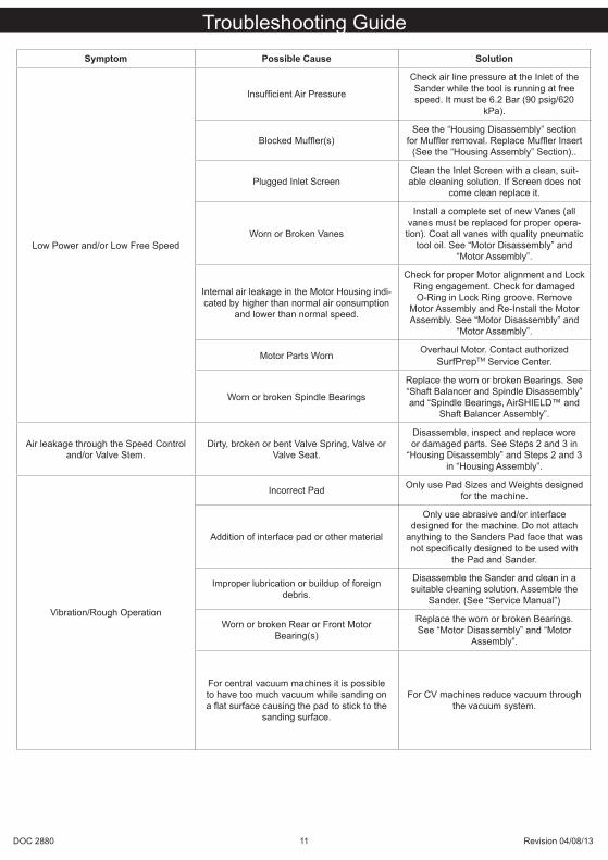
Symptom Possible Cause Solution
Low Power and/or Low Free Speed
Insufficient Air Pressure
Check air line pressure at the Inlet of the Sander while the tool is running at free speed. It must be 6.2 Bar (90 psig/620
kPa).
Blocked Muffler(s)See the “Housing Disassembly” section
for Muffler removal. Replace Muffler Insert (See the “Housing Assembly” Section)..
Plugged Inlet ScreenClean the Inlet Screen with a clean, suit-able cleaning solution. If Screen does not
come clean replace it.
Worn or Broken Vanes
Install a complete set of new Vanes (all vanes must be replaced for proper opera-tion). Coat all vanes with quality pneumatic
tool oil. See “Motor Disassembly” and “Motor Assembly”.
Internal air leakage in the Motor Housing indi-cated by higher than normal air consumption
and lower than normal speed.
Check for proper Motor alignment and Lock Ring engagement. Check for damaged O-Ring in Lock Ring groove. Remove
Motor Assembly and Re-Install the Motor Assembly. See “Motor Disassembly” and
“Motor Assembly”.
Motor Parts Worn Overhaul Motor. Contact authorizedSurfPrepTM Service Center.
Worn or broken Spindle Bearings
Replace the worn or broken Bearings. See “Shaft Balancer and Spindle Disassembly” and “Spindle Bearings, AirSHIELD™ and
Shaft Balancer Assembly”.
Air leakage through the Speed Control and/or Valve Stem.
Dirty, broken or bent Valve Spring, Valve or Valve Seat.
Disassemble, inspect and replace wore or damaged parts. See Steps 2 and 3 in
“Housing Disassembly” and Steps 2 and 3 in “Housing Assembly”.
Vibration/Rough Operation
Incorrect Pad Only use Pad Sizes and Weights designed for the machine.
Addition of interface pad or other material
Only use abrasive and/or interface designed for the machine. Do not attach
anything to the Sanders Pad face that was not specifically designed to be used with
the Pad and Sander.
Improper lubrication or buildup of foreign debris.
Disassemble the Sander and clean in a suitable cleaning solution. Assemble the
Sander. (See “Service Manual”)
Worn or broken Rear or Front Motor Bearing(s)
Replace the worn or broken Bearings. See “Motor Disassembly” and “Motor
Assembly”.
For central vacuum machines it is possible to have too much vacuum while sanding on a flat surface causing the pad to stick to the
sanding surface.
For CV machines reduce vacuum through the vacuum system.
Troubleshooting Guide

SurfPrepTM Tools571 BIRCH STREET LAKE ELSINORE, CA 92530
Tel : 951-245-4200Fax: 951-245-4299