Embed Size (px)
Citation preview

i
Thank Youfor your purchase of one of the finest marine power packagesavailable. It incorporates numerous design features to assureoperating ease and durability.With proper care and maintenance, you will thoroughly enjoyusing this product for many boating seasons. To ensuremaximum performance and carefree use, we ask that youthoroughly read this manual.The Operation, Maintenance & Warranty Manual containsspecific instructions for using and maintaining your product.We suggest that this manual remain with the product for readyreference whenever you are on the water.Again, thank you for purchasing one of our Mercury Marineproducts. We sincerely hope your boating will be pleasant!
Mercury Racing, N7480 County Road "UU" Fond du Lac, WI 54935-9585
7406
Warranty Message
! WARNINGThe operator (driver) is responsible for the correct and safeoperation of the boat, the equipment aboard and the safetyof all occupants aboard. We strongly recommend that theoperator read this Operation, Maintenance and WarrantyManual and thoroughly understand the operationalinstructions for the power package and all relatedaccessories before the boat is used.
© 2
008
Mer
cury
Mar
ine
HP5
25 E
FI (N
XT¹ D
rive)
90-8
M80
2225
1 1
008

ii
The product you have purchased comes with a limited warrantyfrom Mercury Marine; the terms of the warranty are set forth in theWarranty Information section of this manual. The warrantystatement contains a description of what is covered, what is notcovered, the duration of coverage, how to best obtain warrantycoverage, important disclaimers and limitations of damages, andother related information. Please review this important information.
Safety Alerts and NoticesThroughout this publication, dangers, warnings, cautions, and
notices., accompanied by the international HAZARD symbol ! ,are used to alert the boat operator and technician to specialinstructions concerning a particular service or operation that maybe hazardous if performed incorrectly or carelessly. Observe thesesafety alerts carefully.These safety alerts alone can not eliminate the hazards theysignal. Strict compliance to these special instructions whenperforming the service, and common sense operation are majoraccident prevention measures.
! DANGERIndicates a hazardous situation which, if not avoided, will resultin death or serious injury.
! WARNINGIndicates a hazardous situation which, if not avoided, could resultin death or serious injury.
! CAUTIONIndicates a hazardous situation which, if not avoided, could resultin minor or moderate injury.
NOTICEIndicates a situation which, if not avoided, could result in engineor major component failure.
.

iii
IMPORTANT: Identifies information essential to the successfulcompletion of the task.NOTE: Indicates information that helps in the understanding of aparticular step or action.
! WARNINGThe engine exhaust from this product contains chemicals knownto the state of California to cause cancer, birth defects or otherreproductive harm.
Copyright and Trademark InformationMercury Marine, Fond du Lac, Wisconsin U.S.A.Printed in U.S.A.© 2008, Mercury MarineMercury, Mercury Marine, MerCruiser, Mercury MerCruiser,Mercury Racing, Mercury Precision Parts, Mercury Propellers,Mariner, Verado, Vazer, #1 On The Water, Alpha, Bravo, Pro Max,OptiMax, Sport‑Jet, K‑Planes, MerCathode, SmartCraft,VesselView, Quicksilver, Zero Effort, M with Waves logo, Mercurywith Waves logo, and SmartCraft logo are all registeredtrademarks of Brunswick Corporation. Mercury Product Protectionlogo is a registered service mark of Brunswick Corporation.

iv

TABLE OF CONTENTS
v
Warranty Information
Warranty Registration United States And Canada......................1Transfer of Warranty....................................................................1Mercury Racing Division One Year Limited Warranty.................2Warranty Against Corrosion (Worldwide)....................................6Products Sold to Government Agencies......................................6Warranty Coverage and Exclusions for Mercury Racing SterndriveProducts.......................................................................................7
General Information
Boater's Responsibilities..............................................................9Before Operating Your Boat........................................................9Boat Horsepower Capacity........................................................10High‑Speed and High‑Performance Boat Operation................. 10Lanyard Stop Switch..................................................................11Trailering Boat........................................................................... 12Protecting People In The Water.................................................12Exhaust Emissions.................................................................... 13Wave And Wake Jumping......................................................... 15Impact With Underwater Hazards..............................................16Safe Boating Suggestions......................................................... 17Stolen Power Package.............................................................. 20
Specifications
Power Package Identification.................................................... 21Fuel Requirements.................................................................... 23Crankcase Oil............................................................................25Capacities..................................................................................26General Engine Specifications...................................................27Engine Operating Limitations.....................................................28California Emissions Regulations..............................................29Engine Break‑in.........................................................................29After Break‑In Period.................................................................29

TABLE OF CONTENTS
vi
Operation
Instrumentation..........................................................................31Warning System........................................................................31Electrical System Overload Protection......................................34Remote Controls (Console Mounted Zero Effort)......................37Power Trim................................................................................38Starting, Shifting and Stopping..................................................42Operation Chart.........................................................................44Freezing Temperature Operation..............................................45Drain Plug and Bilge Pump........................................................45Launching And Boat Operation Care.........................................45
Conditions Affecting Operation
Weight Distribution.....................................................................46Bottom Of Boat..........................................................................46Cavitation...................................................................................46Ventilation..................................................................................47Propeller Selection.....................................................................47Conditions That Lower Engine Performance.............................48
TABLE OF CONTENTS
vii
Maintenance
Service Responsibilities.............................................................49Replacement Service Parts.......................................................50Do‑It‑Yourself Maintenance Suggestions..................................50Servicing High Horsepower Engines.........................................52Maintenance Charts...................................................................52Checking Fluids.........................................................................57Changing Fluids.........................................................................66Lubrication.................................................................................77Maximus Propeller Installation (NXT¹).......................................78Sterndrive Cleaver Propeller Installation (NXT¹)........................80Cleaver Propeller Installation (SSM)..........................................83Flushing Cooling System...........................................................85Seawater Pump Impeller Inspection..........................................85Cleaning Seawater (Raw Water) Section of the Coolers...........86Changing Positive Crankcase Ventilation Valve........................88Serpentine Drive Belt.................................................................89Changing Fuel Filters.................................................................91Corrosion and Corrosion Protection..........................................93Battery.......................................................................................96Bottom of Boat...........................................................................97Inspection and Maintenance......................................................97Attention Required After Submersion........................................98
Cold Weather or Extended Storage
Power Package Lay‑up..............................................................99Engine Draining Instructions....................................................101Battery Winter Storage............................................................ 104Power Package Recommissioning.......................................... 105

TABLE OF CONTENTS
viii
Troubleshooting
Engine Will Not Crank..............................................................108Engine Cranks But Will Not Start.............................................109Engine Hard to Start, Runs Rough, Misses, and/or Backfires. 109Low Engine Coolant (Closed Cooling) Temperature............... 110Poor Performance....................................................................110Insufficient Engine Temperature..............................................110Excessive Engine Temperature...............................................111Low Engine Oil Pressure.........................................................111Battery Will Not Come Up On Charge.....................................112Power Trim Does Not Operate (Motor Doesn't Run)...............112Power Trim Does Not Operate (Motor Runs But Drive Unit DoesNot Move)................................................................................112Remote Control Operates Hard, Binds, Has Excessive Free‑Playor Makes Unusual Sounds.......................................................113Steering Wheel Turns Hard or Jerky.......................................113
Owner Service Assistance
Local Repair Service................................................................114Service Away from Home........................................................114Parts and Accessories Inquiries..............................................114Service Assistance..................................................................114Mercury Mercruiser Service Offices.........................................115
Ordering Literature
United States and Canada.......................................................117Outside The United States and Canada..................................117
Maintenance Log
Maintenance Log.....................................................................118

WARRANTY INFORMATION
1
Warranty Registration United States And CanadaOutside United States and Canada ‑ Check with your localdistributor.1. You may change your address at any time, including at time
of warranty claim, by calling Mercury Marine or sending a letteror fax with your name, old address, new address, and engineserial number to Mercury Marine’s warranty registrationdepartment. Your dealer can also process this change ofinformation.Mercury MarineAttn.: Warranty Registration DepartmentW6250 W. Pioneer RoadP.O. Box 1939Fond du Lac, WI 54936-1939920-929-5054Fax 920-929-5893
NOTE: Registration lists must be maintained by Mercury Marineand any dealer on marine products sold in the United States,should a safety recall notification under the Federal Safety Act berequired.2. At the time of sale, the dealer should complete the warranty
registration and immediately submit it to Mercury Marine viaMercNET, E‑mail, or mail. Upon receipt of this warrantyregistration, Mercury Marine will record the registration.
IMPORTANT: Your warranty coverage begins at the time of sale,but warranty claims cannot be processed until the product isregistered with Mercury Marine.3. Upon processing the warranty registration, Mercury Marine
will send the purchaser a Mercury Owner Resource Guide.The back page of this guide contains your warrantyregistration information and should be saved. If thisregistration verification is not received within 30 days, pleasecontact your selling dealer immediately.
Transfer of WarrantyThe limited warranty is transferable to a subsequent purchaser, butonly for the remainder of the unused portion of the limited warranty.This will not apply to products used for commercial applications.

WARRANTY INFORMATION
2
To transfer the warranty to the subsequent owner, send or fax acopy of the bill of sale or purchase agreement, new owner’s name,address and engine serial number to Mercury Marine’s warrantyregistration department. In the United States and Canada, mail to:Mercury MarineAttn: Warranty Registration DepartmentW6250 W. Pioneer RoadP.O. Box 1939Fond du Lac, WI 54936-1939920-929-5054Fax +1 920 929 5893Upon processing the transfer of warranty, Mercury Marine will sendregistration verification to the new owner of the product by mail.There is no charge for this service.For products purchased outside the United States and Canada,contact the distributor in your country, or the Marine Power ServiceCenter closest to you.
Mercury Racing Division One Year Limited WarrantyWHAT IS COVEREDMercury Marine warrants its new products (and remanufacturedproducts sold under the trade name "Pacemaker") to be free ofdefects in material and workmanship during the period describedbelow.DURATION OF COVERAGEThis Limited Warranty provides coverage for one (1) year fromeither the date the product is first sold to a recreational use retailpurchaser, or the date on which the product is first put into service,whichever occurs first. The repair or replacement of parts, or theperformance of service under this warranty, does not extend thelife of this warranty beyond its original expiration date. Unexpiredwarranty coverage can be transferred to a subsequent purchaserupon proper re‑registration of the product.

WARRANTY INFORMATION
3
CONDITIONS THAT MUST BE MET IN ORDER TO OBTAINWARRANTY COVERAGEWarranty coverage is available only to retail customers thatpurchase from a Dealer authorized by Mercury Marine to distributethe product in the country in which the sale occurred, and then onlyafter the Mercury Marine specified pre‑delivery inspection processis completed and documented. Warranty coverage becomesavailable upon proper registration of the product by the authorizeddealer. Inaccurate warranty registration information regardingrecreational use, or subsequent change of use from recreationalto commercial may void the warranty at the sole discretion ofMercury Marine. Routine maintenance outlined in the Operationand Maintenance Manual must be timely performed in order tomaintain warranty coverage. Mercury Marine reserves the right tomake warranty coverage contingent upon proof of propermaintenance.WHAT MERCURY WILL DOMercury’s sole and exclusive obligation under this warranty islimited to, at our option, repairing a defective part, replacing suchpart or parts with new or Mercury Marine certified re‑manufacturedparts, or refunding the purchase price of the Mercury product.Mercury reserves the right to improve or modify products from timeto time without assuming an obligation to modify productspreviously manufactured.

WARRANTY INFORMATION
4
HOW TO OBTAIN WARRANTY COVERAGEThe customer must provide Mercury with a reasonable opportunityto repair and reasonable access to the product for warrantyservice. Warranty claims shall be made by delivering the productfor inspection to a Mercury dealer authorized to service theproduct. If purchaser cannot deliver the product to such a dealer,written notice must be given to Mercury. We will then arrange forthe inspection and any covered repair. Purchaser in that case shallpay for all related transportation charges and/or travel time. If theservice provided is not covered by this warranty, purchaser shallpay for all related labor and material, and any other expensesassociated with that service. Purchaser shall not, unless requestedby Mercury, ship the product or parts of the product directly toMercury. Proof of registered ownership must be presented to thedealer at the time warranty service is requested in order to obtaincoverage.

WARRANTY INFORMATION
5
WHAT IS NOT COVEREDThis limited warranty does not cover routine maintenance items,tune ups, adjustments, normal wear and tear, damage caused byabuse, abnormal use, use of a propeller or gear ratio that does notallow the engine to run in its recommended wide‑open‑throttleRPM range (see the Operation and Maintenance Manual),operation of the product in a manner inconsistent with therecommended operation/duty cycle section of the Operation andMaintenance Manual, neglect, accident, submersion, improperinstallation (proper installation specifications and techniques areset forth in the installation instructions for the product), improperservice, use of an accessory or part not manufactured or sold byus, operation with fuels, oils or lubricants which are not suitable foruse with the product (see the Operation and MaintenanceManual), alteration or removal of parts, water entering the enginethrough the fuel intake, air intake or exhaust system, or damage tothe product from insufficient cooling water caused by blockage ofthe cooling system by a foreign body, running the engine out ofwater, mounting the engine too high on the transom, or running theboat with the engine trimmed out too far. The commercial use ofthe product, defined as any work or employment related use of theproduct, or any income generating use of the product, even if suchuse is only occasional, will void the warranty. Use of the productfor racing or other competitive activity, at any point, even by a priorowner of the product, voids the warranty. Expenses related tohaul‑out, launch, towing, storage, telephone, rental,inconvenience, slip fees, insurance coverage, loan payments, lossof time, loss of income, tournament fees, club fees, prize moneyor any other type of incidental or consequential damages are notcovered by this warranty. Also, expenses associated with theremoval and/or replacement of boat partitions or material causedby boat design for access to the product are not covered by thiswarranty.

WARRANTY INFORMATION
6
No individual or entity, including Mercury Marine authorizeddealers, has been given authority by Mercury Marine to make anyaffirmation, representation or warranty regarding the product,other than those contained in this limited warranty, and if made,shall not be enforceable against Mercury Marine. For additionalinformation regarding events and circumstances covered by thiswarranty, and those that are not, see the Warranty Coveragesection of the Operation and Maintenance Manual, incorporatedby reference into this warranty.DISCLAIMERS AND LIMITATIONS THE IMPLIED WARRANTIESOF MERCHANTABILITY AND FITNESS FOR A PARTICULARPURPOSE ARE EX‑PRESSLY DISCLAIMED. TO THE EXTENTTHAT THEY CANNOT BE DISCLAIMED, THE IMPLIEDWARRANTIES ARE LIMITED IN DURATION TO THE LIFE OFTHE EXPRESS WARRANTY. INCIDENTAL ANDCONSEQUENTIAL DAMAGES ARE EXCLUDED FROMCOVERAGE UNDER THIS WARRANTY. SOME STATES/COUNTRIES DO NOT ALLOW FOR THE DISCLAIMERS,LIMITATIONS AND EXCLUSIONS IDENTIFIED ABOVE, AS ARESULT, THEY MAY NOT APPLY TO YOU. THIS WARRANTYGIVES YOU SPECIFIC LEGAL RIGHTS, AND YOU MAY ALSOHAVE OTHER LEGAL RIGHTS WHICH VARY FROM STATE TOSTATE AND COUNTRY TO COUNTRY.
Warranty Against Corrosion (Worldwide)IMPORTANT: Corrosion failure warranty is not available for thisproduct.
Products Sold to Government AgenciesContact the Mercury Racing Sales Department for a copy of theGovernment Agencies Warranty Packet Kit which explains theconditions required for government agencies to receive warrantywhen purchasing Mercury Racing Outboard or Sterndrive product.Mercury Racing Sales DepartmentN7840 County Road UUFond du Lac, WI 54935920-921-5330Fax 920-921-6533

WARRANTY INFORMATION
7
Warranty Coverage and Exclusions for MercuryRacing Sterndrive ProductsThe purpose of this section is to help eliminate some of the morecommon misunderstandings regarding warranty coverage. Thefollowing information explains some of the types of services thatare not covered by warranty. The provisions set forth followinghave been incorporated by reference into the Mercury RacingDivision Three Year Limited Warranty Against Corrosion Failure,the Mercury Racing Division 90 Day, 6 months and One YearLimited Warranties.Keep in mind that warranty covers repairs that are needed withinthe warranty period because of defects in material andworkmanship. Installation errors, accidents, normal wear, and avariety of other causes that affect the product are not covered.Warranty is limited to defects in material or workmanship, but onlyto retail customers that purchase from a Dealer authorized byMercury Marine to distribute the product in the country in which thesale occurred, and then only after the Mercury Marine specifiedpre‑delivery inspection process is completed and documented.Should you have any questions concerning warranty coverage,contact your authorized dealer. They will be pleased to answer anyquestions that you may have.GENERAL EXCLUSIONS FROM WARRANTY1. Minor adjustments and tune‑ups, including checking, cleaning
or adjusting spark plugs, ignition components, carburetor orEFI settings, filters, belts, controls, and checking lubricationmade in connection with normal services.
2. Damage caused by lack of maintenance.3. Haul‑out, launch, towing charges, and all related
transportation charges and/or travel time, etc.4. Additional service work requested by customer other than that
necessary to satisfy the warranty obligation.

WARRANTY INFORMATION
8
5. Labor performed by other than an authorized dealer may becovered only under following circumstances: When performedon emergency basis (providing there are no authorizeddealers in the area who can perform the work required or haveno facilities to haul out, etc., and prior factory approval hasbeen given to have the work performed at this facility).
6. Use of other than Mercury Precision or Quicksilver parts whenmaking warranty repairs.
7. Engine noise does not necessarily indicate a serious engineproblem. If diagnosis indicates a serious internal enginecondition, which could result in a failure, condition responsiblefor noise should be corrected under the warranty.
8. Lower unit and/or propeller damage caused by striking asubmerged object is considered a marine hazard.
9. Water in the starter motor.10.Starter motors and/or armatures or field coil assembly, which
are burned, or where lead is thrown out of commutatorbecause of excess cranking.
11.Valve or valve seat grinding required because of wear.

GENERAL INFORMATION
9
Boater's ResponsibilitiesThe operator (driver) is responsible for the correct and safeoperation of the boat and safety of its occupants and generalpublic. It is strongly recommended that each operator (driver) readand understand this entire manual before operating the powerpackage.Be sure at least one additional person on board is instructed in thebasics of starting and operating the power package, and boathandling in case the driver is unable to operate the boat.
Before Operating Your BoatRead this manual carefully. Safety and operating information thatis practiced along with using good common sense can help preventpersonal injury and product damage. If you have any questions,contact your dealer.This manual as well as safety labels posted on the engine packageuse safety alerts to draw your attention to special safetyinstructions that must be followed.
! WARNINGIndicates a hazardous situation which, if not avoided, could resultin death or serious injury.
! CAUTIONIndicates a hazardous situation which, if not avoided, could resultin minor or moderate injury.
IMPORTANT: Indicates information or instructions that arenecessary for proper operation and/or maintenance.NOTE: Indicates information that helps in the understanding of astep or action.

GENERAL INFORMATION
10
Boat Horsepower Capacity
! WARNINGExceeding the boat's maximum horsepower rating can causeserious injury or death. Overpowering the boat can affect boatcontrol and flotation characteristics or break the transom. Do notinstall an engine that exceeds the boat's maximum power rating.
Do not overpower or overload your boat. Most boats will carry arequired capacity plate indicating the maximum acceptable powerand load as determined by the manufacturer following certainfederal guidelines. If in doubt, contact your dealer or the boatmanufacturer.
U.S. COAST GUARD CAP ACITYMAXIMUM HORSEPOWER XXXMAXIMUM PERSON CAPACITY (POUNDS) XXXMAXIMUM WEIGHT CAPACITY XXX
26777
High‑Speed and High‑Performance Boat OperationIf your power package is to be used on a high speed or highperformance boat with which you are unfamiliar, we recommendthat you never operate it at its high speed capability without firstrequesting an initial orientation and familiarization demonstrationride with your dealer or an operator experienced with your boat/power package combination. For additional information, obtain acopy of our Hi‑Performance Boat Operation booklet from yourdealer, distributor, or Mercury Marine.
GENERAL INFORMATION
11
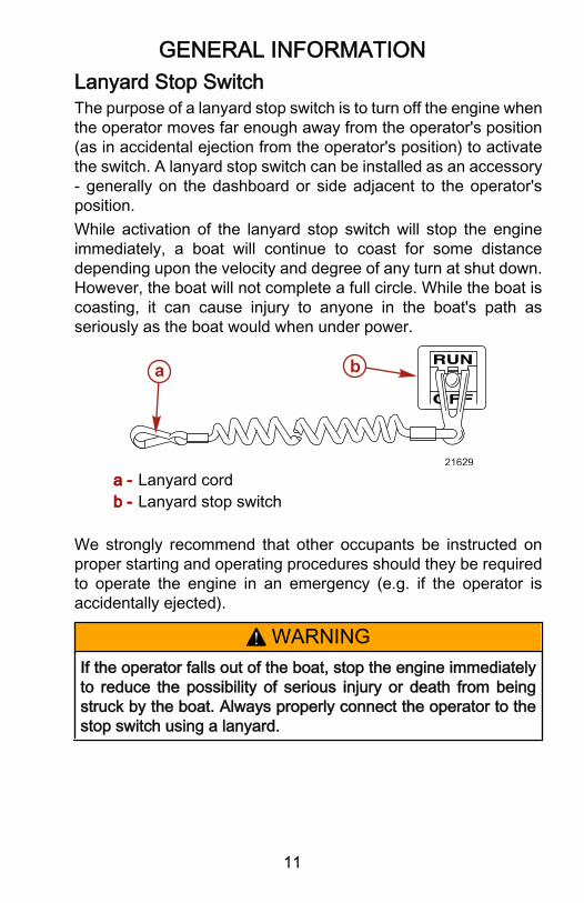
Lanyard Stop SwitchThe purpose of a lanyard stop switch is to turn off the engine whenthe operator moves far enough away from the operator's position(as in accidental ejection from the operator's position) to activatethe switch. A lanyard stop switch can be installed as an accessory‑ generally on the dashboard or side adjacent to the operator'sposition.While activation of the lanyard stop switch will stop the engineimmediately, a boat will continue to coast for some distancedepending upon the velocity and degree of any turn at shut down.However, the boat will not complete a full circle. While the boat iscoasting, it can cause injury to anyone in the boat's path asseriously as the boat would when under power.
21629
a b
a - Lanyard cordb - Lanyard stop switch
We strongly recommend that other occupants be instructed onproper starting and operating procedures should they be requiredto operate the engine in an emergency (e.g. if the operator isaccidentally ejected).
! WARNINGIf the operator falls out of the boat, stop the engine immediatelyto reduce the possibility of serious injury or death from beingstruck by the boat. Always properly connect the operator to thestop switch using a lanyard.

GENERAL INFORMATION
12
! WARNINGAvoid serious injury or death from deceleration forces resultingfrom accidental or unintended stop switch activation. The boatoperator should never leave the operator's station without firstdisconnecting the stop switch lanyard from the operator.
Accidental or unintended activation of the switch during normaloperation is also a possibility. This could cause any, or all, of thefollowing potentially hazardous situations:• Occupants could be thrown forward due to unexpected loss
of forward motion ‑ a particular concern for passengers in thefront of the boat who could be ejected over the bow andpossibly struck by the gear case or propeller.
• Loss of power and directional control in heavy seas, strongcurrent or high winds.
• Loss of control when docking.
Trailering BoatThe boat can be trailered with the drive unit in up or down position.Adequate road clearance is required between road and gearhousing skeg when trailering with the drive unit in down position.If adequate road clearance is a problem, place drive unit in full upposition.
Protecting People In The WaterWHILE YOU ARE CRUISINGIt is very difficult for a person in the water to take quick action toavoid a boat heading in their direction, even at slow speeds.
21604
Always slow down and exercise extreme caution any time you areboating in an area where there might be people in the water.

GENERAL INFORMATION
13
Whenever a boat is moving (even coasting) and the gear shift is inneutral, there is sufficient force by the water on the propeller tocause the propeller to rotate. This neutral propeller rotation cancause serious injury.WHILE BOAT IS STATIONARY
! WARNINGA spinning propeller, a moving boat, or any solid device attachedto the boat can cause serious injury or death to swimmers. Stopthe engine immediately whenever anyone in the water is nearyour boat.
Shift into neutral and shut off the engine before allowing people toswim or be in the water near your boat.
Exhaust EmissionsBE ALERT TO CARBON MONOXIDE POISONINGCarbon monoxide is present in the exhaust fumes of all internalcombustion engines. This includes the outboards, sterndrives andinboard engines that propel boats, as well as the generators thatpower various boat accessories. Carbon monoxide is a deadly gasthat is odorless, colorless and tasteless.Early symptoms of carbon monoxide poisoning which should notbe confused with seasickness or intoxication, include headache,dizziness, drowsiness, and nausea.
! WARNINGCarbon monoxide poisoning can lead to unconsciousness, braindamage, or death. Keep the boat well ventilated while at rest orunderway and avoid prolonged exposure to carbon monoxide.
POOR VENTILATIONUnder certain running and/or wind conditions, permanentlyenclosed or canvas enclosed cabins or cockpits with insufficientventilation may draw in carbon monoxide. Install one or morecarbon monoxide detectors in your boat.

GENERAL INFORMATION
14
Although the occurrence is rare, on a very calm day, swimmersand passengers in an enclosed area of a stationary boat thatcontains or is near a running engine may be exposed to ahazardous level of carbon monoxide.While Boat Is Stationary
21626
ab
a - Running the engine when the boat is moored in a confinedspace.
b - Mooring close to another boat that has its engine running.
While Boat is Moving
5449
a
b
a - Running the boat with the trim angle of the bow too high.b - Running the boat with no forward hatches open (station
wagon effect).
GENERAL INFORMATION
15
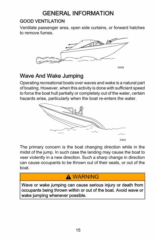
GOOD VENTILATIONVentilate passenger area, open side curtains, or forward hatchesto remove fumes.
5448
Wave And Wake JumpingOperating recreational boats over waves and wake is a natural partof boating. However, when this activity is done with sufficient speedto force the boat hull partially or completely out of the water, certainhazards arise, particularly when the boat re‑enters the water.
5450
The primary concern is the boat changing direction while in themidst of the jump. In such case the landing may cause the boat toveer violently in a new direction. Such a sharp change in directioncan cause occupants to be thrown out of their seats, or out of theboat.
! WARNINGWave or wake jumping can cause serious injury or death fromoccupants being thrown within or out of the boat. Avoid wave orwake jumping whenever possible.

GENERAL INFORMATION
16
There is another less common hazardous result from allowing yourboat to launch off a wave or wake. If the bow of your boat pitchesdown far enough while airborne, upon water contact it maypenetrate under the water surface and submarine for an instant.This will bring the boat to a nearly instantaneous stop and can sendthe occupants flying forward. The boat may also steer sharply toone side.
Impact With Underwater HazardsIMPORTANT: Operating in shallow waters can severely damagethe boat or power package. Maintain a minimum safe speed whenoperating the vessel in shallow waters or in areas with underwaterobstacles.Reduce speed and proceed with caution whenever you drive aboat in shallow water areas, or in areas where you suspectunderwater obstacles may exist which could be struck by thesterndrive or the boat bottom. The most important thing you cando to help reduce injury or impact damage from striking a floatingor underwater object is to control the boat speed. Under theseconditions, boat speed should be kept to a minimum planing speed24 to 40 km/h (15 to 25 MPH)
7462
Striking a floating or underwater object could result in an infinitenumber of situations. Some of these situations could result in thefollowing:• Part of the sterndrive or the entire sterndrive could break loose
and fly into the boat.• The boat could move suddenly in a new direction. Such a
sharp change in direction can cause occupants to be thrownout of their seats or out of the boat.

GENERAL INFORMATION
17
• A rapid reduction in speed. This will cause occupants to bethrown forward, or even out of the boat.
• Impact damage to the sterndrive and/or boat.Keep in mind, the most important thing you can do to help reduceinjury or impact damage during an impact is control the boat speed.Boat speed should be kept to a minimum planing speed whendriving in waters known to have underwater obstacles.
! WARNINGOperating a boat or engine with impact damage can result inproduct damage, serious injury, or death. If the vesselexperiences any form of impact, have an authorized MercuryMarine dealer inspect and repair the vessel or power package.
After striking a submerged object, stop the engine as soon aspossible and inspect it for any broken or loose parts. If damage ispresent or suspected, the sterndrive should be taken to anauthorized dealer for a thorough inspection and necessary repair.The boat should also be checked for any hull fractures, transomfractures, or water leaks.Operating a damaged sterndrive could cause additional damageto other parts of the sterndrive, or could affect control of the boat.If continued running is necessary, do so at greatly reduced speeds.
Safe Boating SuggestionsIn order to safely enjoy the waterways, familiarize yourself withlocal and other governmental boating regulations and restrictions,and consider the following suggestions.Use flotation devices. Have an approved personal flotation deviceof suitable size for each person aboard (it is the law) and have itreadily accessible.Do not overload your boat. Most boats are rated and certified formaximum load (weight) capacities (refer to your boat capacityplate). If in doubt, contact your dealer or the boats manufacturer.Perform safety checks and required maintenance. Follow a regularschedule and ensure that all repairs are properly made.

GENERAL INFORMATION
18
Check safety equipment on-board. Here are suggestions of thetypes of safety equipment to carry when boating:• Approved fire extinguisher; paddle or oar.• Signal devices: flashlight, rockets or flares, flag and whistle or
horn.• Spare propeller, thrust hubs and an appropriate wrench.• Tools for necessary minor repairs; first aid kit and book.• Anchor, extra anchor line; water‑proof storage containers.• Manual bilge pump and extra drain plugs; compass and map
or chart of area.• Spare operating equipment; batteries, bulbs, fuses, etc.• Transistor radio and drinking water.Know signs of weather change and avoid foul weather andrough-sea boating.Tell someone where you are going and when you expect toreturn.Know and obey all nautical rules and laws of the waterways. Boatoperators should complete a boating safety course. Courses areoffered in the U.S.A. by:1. The U.S. Coast Guard Auxiliary2. The Power Squadron3. The Red Cross4. Your state boating law enforcement agencyDirect all inquiries to the Boat U.S. Foundation information number1‑800‑336‑BOAT (2626).We strongly recommend that all powerboat operators attend oneof these courses.You should also review the NMMA Sources of WaterwayInformation booklet. It lists regional sources of safety, cruising andlocal navigation and is available at no charge by writing to:
Sources of Waterway InformationNational Marine Manufacturers Association410 N. Michigan AvenueChicago, IL 60611 U.S.A.

GENERAL INFORMATION
19
Make sure everyone in the boat is properly seated. Do not allowanyone to sit or ride on any part of the boat that was not intendedfor such use. This includes the back of seats, gunwales, transom,bow, decks, raised fishing seats, any rotating fishing seat; oranywhere that an unexpected acceleration, sudden stopping,unexpected loss of boat control, or sudden boat movement couldcause a person to be thrown overboard or into the boat.Never be under the influence of alcohol or drugs while boating (itis the law). Alcohol or drug use impairs your judgment and greatlyreduces your ability to react quickly.Know your boating area and avoid hazardous locations.Prepare other boat operators. Instruct at least one other person onboard in the basics of starting and operating the power package,and boat handling, in case the driver becomes disabled or fallsoverboard.Passenger boarding. Stop the engine whenever passengers areboarding, unloading, or are near the back (stern) of the boat. Justshifting the power package into neutral is not sufficient.Be alert. The operator of the boat is responsible by law to maintaina proper lookout by sight and hearing. The operator must have anunobstructed view particularly to the front. No passengers, load,or fishing seats should block the operators view when operatingthe boat above idle speed.Never drive your boat directly behind a water skier in case the skierfalls. As an example, your boat traveling at 40 km/h (25 MPH) willovertake a fallen skier 61 m (200 ft.) in front of you in five seconds.Watch fallen skiers. When using your boat for water skiing orsimilar activities, always keep a fallen or down skier on theoperator's side of the boat while returning to assist the skier. Theoperator should always have the down skier in sight and neverback up to the skier or anyone in the water.Report accidents. Boat operators are required by law to file aBoating Accident Report with their state boating law enforcementagency when their boat is involved in certain boating accidents. Aboating accident must be reported if:1. There is loss of life or probable loss of life

GENERAL INFORMATION
20
2. There is personal injury requiring medical treatment beyondfirst aid
3. There is damage to boats or other property where the damagevalue exceeds $500.00
4. There is complete loss of the boatIMPORTANT: Seek further assistance from local law enforcementfor a complete list of rules and regulations.
Stolen Power PackageIf your power package is stolen, immediately advise the localauthorities and Mercury Marine of the model and serial number(s)and to whom the recovery is to be reported. This Stolen PowerPackage information is placed into a file at Mercury Marine to aidauthorities and dealers in recovery of stolen engines.

SPECIFICATIONS
21
Power Package IdentificationModel:Displacement:Max WOT RPM:Spark Plugs:Spark Plug Gap:Spark Timing:Fuel Octane:
Engine Oil:Engine Coolant:
**see owner's manual
HP525 EFI502 C.I.D.4800 - 5200NGK BPR6ES0.035 Inch**non-adjustable87 (R+M)/2 or92 RON International**Quicksilver 25W40Dex-Cool ®
SERIAL NUMBERSENGINE
DRIVE
TRANSOM
a
6254
a - Engine identification placard
SPECIFICATIONS
22
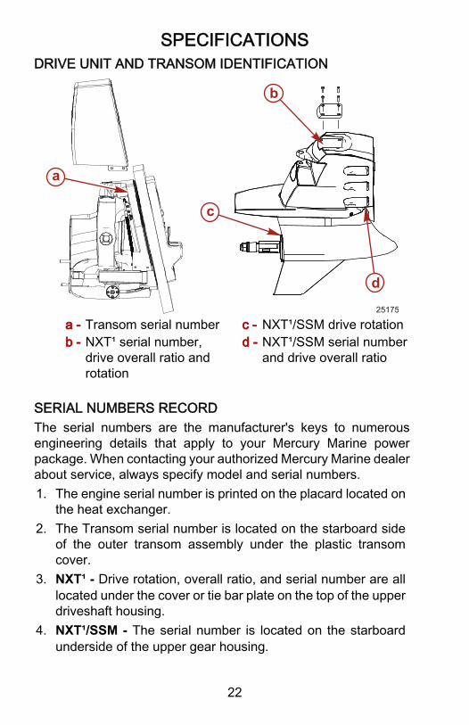
DRIVE UNIT AND TRANSOM IDENTIFICATION
25175
a
b
c
d
a - Transom serial numberb - NXT¹ serial number,
drive overall ratio androtation
c - NXT¹/SSM drive rotationd - NXT¹/SSM serial number
and drive overall ratio
SERIAL NUMBERS RECORDThe serial numbers are the manufacturer's keys to numerousengineering details that apply to your Mercury Marine powerpackage. When contacting your authorized Mercury Marine dealerabout service, always specify model and serial numbers.1. The engine serial number is printed on the placard located on
the heat exchanger.2. The Transom serial number is located on the starboard side
of the outer transom assembly under the plastic transomcover.
3. NXT¹ - Drive rotation, overall ratio, and serial number are alllocated under the cover or tie bar plate on the top of the upperdriveshaft housing.
4. NXT¹/SSM - The serial number is located on the starboardunderside of the upper gear housing.

SPECIFICATIONS
23
5. NXT¹/SSM - The gear ratio is stamped on the bolt headlocated next to the serial number label.
6. NXT¹/SSM - The running rotation is stamped on the back ofthe gearcase strut.
Fuel RequirementsUse a major brand of unleaded gasoline, preferably withoutalcohol. Mercury Marine recommends fuels that contain fuelinjector cleaner for added internal cleanliness.
! WARNINGFuel leakage is a fire or explosion hazard, which can causeserious injury or death. Periodically inspect all fuel systemcomponents for leaks, softening, hardening, swelling, orcorrosion, particularly after storage. Any sign of leakage ordeterioration requires replacement before further engineoperation.
NOTICEThe use of improper fuel can cause serious damage to theengine. Damage resulting from the use of improper fuel isconsidered engine misuse and is not covered under the limitedwarranty. Use only the recommended fuel in the engine.
OCTANE REQUIREMENTS (U.S./CANADA)
FUEL TYPE MINIMUM POSTED OCTANE
Unleaded regular or premium1. (R+M) ÷ 2 = 87 or RON = 92*
NOTE: *Research Octane NumberOCTANE REQUIREMENTS (OUTSIDE THE U.S./CANADA)
FUEL TYPE MINIMUM POSTED OCTANE
Unleaded regular or premium 2. (R+M) ÷ 2 = 87 or RON = 92*
NOTE: *Research Octane Number
1. The use of premium unleaded fuels with octane ratings higher than (R+M) ÷2 = 87 are acceptable to use but will not give any increase in performance ordurability.

SPECIFICATIONS
24
USING REFORMULATED (OXYGENATED) FUELS (USAONLY)This type of fuel is required in certain areas of the U.S. The twotypes of oxygenates used in these fuels are alcohol (Ethanol) orEther (MTBE or ETBE). If Ethanol is the oxygenate that is used inthe gasoline in your area, refer to the Fuel Containing Alcoholsection.These reformulated fuels are acceptable for use in your Mercuryengine.FUEL CONTAINING ALCOHOLIf the fuel in your area contains either methanol (methyl alcohol) orethanol (ethyl alcohol), you should be aware of certain adverseeffects that can occur. These adverse effects are more severe withmethanol. Increasing the percentage of alcohol in the fuel can alsoworsen these adverse effects.Some of these adverse effects are caused because the alcohol inthe fuel can absorb moisture from the air, resulting in a separationof the water/alcohol from the gasoline in the fuel tank.The fuel system components on your Mercury engine willwithstand up to 10% alcohol content in the gasoline. We do notknow what percentage your boat’s fuel system will withstand.Contact your boat manufacturer for specific recommendations onthe boats fuel system components (fuel tanks, fuel lines, andfittings).Fuel containing alcohol may increase:• Corrosion of metal parts.• Deterioration of rubber or plastic parts.• Fuel permeation through rubber fuel lines.• Starting and operating difficulties.
2. Mercury Racing does not recommend using leaded gasoline. Leaded gasolineis acceptable in areas where unleaded gasoline is not available; however, leadparticles may build up in the exhaust passages and/or the combustionchambers.

SPECIFICATIONS
25
IMPORTANT: Operating a Mercury Marine engine with gasolinecontaining alcohol creates unique problems as a result of longstorage periods common to a boat. Cars normally consumealcohol‑blend fuels before they absorb enough moisture to causeproblems; however, boats often sit idle long enough for phaseseparation to occur. In addition, alcohol can wash protective oilfilms from internal components causing corrosion.IMPORTANT: Because of possible adverse effects of alcohol ingasoline, it is recommended that only alcohol‑free fuel be usedwhere possible.If only fuel containing alcohol is available, or if the presence ofalcohol is unknown, increased inspection frequency for leaks andabnormalities is required.
Crankcase OilPreferred Oils API Classification
Mercury 4‑cycle Marine Engine Oil 25W‑40 SH,SG,CF/CF‑2Oil Filter Should Always Be Changed With Oil
IMPORTANT OIL PRACTICES
Do Not Use• Straight weight oils• Non‑detergent oils• Oils containing solid additives• Multi‑viscosity oils other than the ones recommended• Low quality oils
Do Not Mix
• Different brands of oils, straight weight or multi‑viscosity• Different weights of straight weight or different weights of multi‑viscosity
oils.

SPECIFICATIONS
26
TEMPERATURE/OIL VISCOSITY CHART
Multi-viscosity Oil
-20 0 +20 +40 +60 +80 +100 F
C
SH, SG, CF/CF-2
-20 -30 -10 +20 0 +30 +40 +10
Mercury/Quicksilver 25W 40
8057
CapacitiesUnit Capacity Fluid Type
Crankcase OilCapacity with NewFilter1.
7.6 L (8 U.S. qts) MerCruiser 25w‑40 4 Cycle
Closed CoolingSystem 13 L (14 U.S. qts) Dex‑Cool Extended Life
Anitfreeze/Coolant (50‑50 mix)Transom BearingCavity and Reservoir 0.47 L (0.5 U.S. qts) High Performance Gear Lube
Transmission Approximately 1.0liter (1.1 U.S. qt.) High Performance Gear Lube
NXT¹ Drive UnitCapacity 4.0 L (4.25 U.S. qts) High Performance Gear Lube
Six Drive Unit OilCapacity 4 L (4.25 U.S. qts) Torco MTF Gear Lube
1. Always use dipstick to determine exact quantity of oil required.

SPECIFICATIONS
27
General Engine SpecificationsCrankshaft Horsepower1. 391 KW 525 HP
Displacement 8.2 L (502 c.i.)Cylinder arrangement V‑8Bore 114 mm (4.47 in.)Stroke 102 mm (4.00 in.)Compression ratio 8.75:1Alternator 65 amp / 917 wattBattery requirements 750 CCA 950 MCA (180 Amp Hrs.)Electrical System 12 Volt Negative (‑) GroundIgnition type PCM Distributorless Wasted Spark ControlSpark plug type 810883 (NGK BPR6ES)Spark plug gap 0.9 mm (0.035 in.)Fuel system Sequential Port Electronic Fuel InjectionWeight 545 kg 1201 lbs
1. Kilowatts/horsepower rating is in compliance with the SAE J1228/ISO 3046Standard. Usable power will be reduced by gear losses.

SPECIFICATIONS
28
Engine Operating LimitationsMaximum wide open throttle (W.O.T.) RPM 4800 ‑ 5200 RPM
Rev limit 1. 5400 RPM
Idle RPM in gear 700 RPMIdle RPM out of gear 750 RPMMaximum fuel system flow rate 163 L/hr (43 gals/hr) at 5200 RPMFuel pressure at Sea Level 262‑296 kPa (38‑43 psi)Coolant thermostat initially opens attemperature 62° C (143° F)
Coolant thermostat is at maximum open attemperature 71° C (160° F)
Minimum water pressure supplied to theengine at WOT 138 kPa (20 psi)
Maximum water pressure supplied to theengine at WOT 296 kPa (43 psi)
Minimum oil pressure at idle (Hot) 138 kPa (20 psi)Minimum oil pressure at WOT (Hot) 331 kPa (48 psi)Maximum oil temperature 121° C (250° F)
1
2
3
4
5
6
7
86985
a
b
b
a - Front of engine and boatb - Firing order 1‑8‑4‑3‑6‑5‑7‑2
1. Engines are equipped with an ignition system that has a built‑in 5400 RPMrev limiter. Engine is performing normally if it will not exceed this RPM.

SPECIFICATIONS
29
California Emissions RegulationsAn emission certification label, showing emission levels andengine specifications directly related to emissions, is placed on theengine at the time of manufacture.
EMISSION CONTROL INFORMATION
THIS ENGINE IS RATED AT GREATER THAN 500 HP (CRANKSHAFT) AND IS THEREFORE EXEMPT FROM CALIFORNIA EMISSIONS REGULATIONS FOR SPARK - IGNITION MARINE ENGINES.
6104
Engine Break‑inIMPORTANT: Failure to follow the engine break‑in procedures canresult in poor performance throughout the life of the engine andcan cause engine damage. Always follow break‑in procedures.
5 Hr. Break‑in Procedure• Allow engine to warm‑up for 30‑ 60 seconds.• Do not exceed 3/4 throttle.• Avoid full throttle acceleration from idle speed.• Always vary throttle setting.• Run engine the majority of time between 3000 ‑ 4500 RPM.• Frequently check engine oil level. Add oil if needed. It is normal for oil
consumption to be high during break‑in period.
After Break‑In PeriodTo help extend the life of your power package, Mercury Marinerecommends the following:

SPECIFICATIONS
30
After 5 hr. Break‑in• Use a propeller that allows the engine to operate at or near the top of the
maximum RPM range (See Specifications section) when at full throttlewith a normal boat load.
• Do not advance the throttle until the engine runs smoothly at idle and watertemperature reaches a minimum of 54 °C (130 °F). Do not operate at fullthrottle until the engine oil temperature reaches 60 °C (140 °F).
• Follow the maintenance schedule in this manual.

OPERATION
31
InstrumentationMercury Racing requires that the following critical enginefunctions be monitored:• Oil pressure• Engine RPM• Oil temperature• Water temperature• System voltage• Guardian fault messagesThe use of SmartCraft instrumentation will display all of theabove critical engine functions as well as others not listed.SmartCraft instrumentation will also display informationabout power train sensor faults and Guardian activation.
Warning SystemThe engine's warning system includes an audible alert consistingof a horn located in the helm harness, and the Engine Guardiansystem. Do not attempt to alter or disable the warning system inany way.
NOTICEA continuous horn indicates a critical fault. Operating the engineduring a critical fault can damage components. If the warninghorn emits a continuous beep, do not operate the engine unlessavoiding a hazardous situation.
ENGINE GUARDIAN SYSTEMThe Engine Guardian system monitors sensors on the engine forany early indications of problems. If a sensor indicates a fault, thesystem responds to the problem by emitting a continuous orintermittent horn and, depending on the type of fault, may reduceengine power to provide engine protection. If the boat is equippedwith System View, a message will be given on the display screenin conjunction with the horn. Refer to the System View manual fordetails. When the key switch is turned "ON", the warning system'shorn beeps once to verify horn operation.

OPERATION
32
Fault Type and Related Warning Signal• Critical ‑ Steady horn• Severe ‑ 5 beeps, each 3 seconds long• Warning ‑ 3 beeps, each 1.5 seconds long• Caution ‑ 2 beeps, each 1 second long• To stop an activated horn warning, turn off the engine. If the
horn continues to sound on restart, the system detected a faultagain. See your Mercury Marine dealer to correct the problemas soon as possible.
• If on restart the beeping stops, the problem does not needimmediate attention but will require you to see your authorizedMercury Marine dealer to diagnose and clear the fault.
If the Propulsion Control Module (PCM) detects a fault signal froman engine sensor, it records a fault code. A Digital DiagnosticTerminal (DDT) or Computer Diagnostic System (CDS) is requiredto extract specific problem codes from the PCM.WARNING SYSTEM TABLEThe following table is divided into four columns. The PossibleCause column lists items that could be initiating the fault. The Horncolumn lists the type of audible alert that will be given if a fault isdetected. If the boat is equipped with System View, the MonitorDisplay column indicates whether or not a message will be givenon the screen. The Guardian Activated and Engine PowerReduced column indicates if the PCM will reduce engine power orforce the engine into an idle based on the severity of the problem.The table lists only the possible problem areas and not specificerror codes or messages recorded by the PCM.
Possible Cause Horn Monitor Display
GuardianActivated andEngine Power
ReducedPCM Error Steady Horn Yes Forced Idle
Guardian Invoked Steady Horn Yes NoEngine Overspeed Steady Horn Yes No
Low SeawaterPressure Steady Horn Yes Yes

OPERATION
33
Possible Cause Horn Monitor Display
GuardianActivated andEngine Power
ReducedSeawater Pressure
Sensor Failure3 Beeps‑1.5 Sec.
Long Yes No
Coolant Overheat Steady Horn Yes YesCoolant Temperature
Sensor Failure3 Beeps‑1.5 Sec.
Long Yes No
Low Oil Pressure Steady Horn Yes YesOil Pressure Sensor
Failure3 Beeps‑1.5 Sec.
Long Yes Yes
Oil Temperature High Steady Horn Yes NoOil TemperatureSensor Failure
3 Beeps‑1.5 Sec.Long Yes No
Charge TemperatureHigh Steady Horn Yes No
Charge TemperatureSensor Failure
3 Beeps‑1.5 Sec.Long Yes No
Crankshaft PositionSensor Rationale Steady Horn Yes Yes
MAP Sensor Error 5 Beeps‑3 Sec.Long Yes No
Coil Pack Failure 5 Beeps‑3 Sec.Long Yes No
Fuel Injector Failure 5 Beeps‑3 Sec.Long Yes No
Fuel Pump Failure 5 Beeps‑3 Sec.Long Yes No
Fuel Pressure SensorFailure
3 Beeps‑1.5 Sec.Long Yes No
Idle Air Control Failure 5 Beeps‑3 Sec.Long Yes No
Cam SensorRationale
3 Beeps‑1.5 Sec.Long Yes No
Throttle PositionSensor Failure
3 Beeps‑1.5 Sec.Long Yes Yes
Low Battery Voltage 3 Beeps‑1.5 Sec.Long Yes No
OPERATION
34
Possible Cause Horn Monitor Display
GuardianActivated andEngine Power
ReducedBattery Range high or
low3 Beeps‑1.5 Sec.
LongYes Yes
Low Drive Lube orTransmission Oil
Temperature too high
2 Beeps‑1 Sec.Long Yes No
Lanyard Switchactivated
2 Beeps‑1 Sec.Long Yes No
Electrical System Overload ProtectionIf an electrical overload occurs, a fuse or circuit breaker opens.Locate and correct the problem before replacing the fuse orresetting the circuit breaker.A circuit breaker protects the engine wiring harness andinstrumentation power lead. Reset by pushing the reset button.In an emergency, if you cannot locate and correct the cause of thehigh current draw, and you must operate the engine, perform thefollowing:1. Turn off or disconnect all accessories connected to the engine
and instrumentation wiring and reset the circuit breaker.2. If the breaker remains open, an electrical overload is still
present. Inspect the electrical system.3. Some key switches have a 20 amp fuse located in‑line with
the ignition switch harness to protect the electrical system.Check for an open fuse if the key is turned to "START" andnothing happens (and the circuit breaker is not open).
4. An 90 amp overload fuse or circuit breaker located within 102cm (40 in.) of the battery switch or battery provides protectionfor the power trim system. An in line 10 amp fuse protects thetrim switch.

OPERATION
35
5. If installed for corrosion protection, the MerCathode Systemhas a 20 amp in‑line fuse in the wire which connects to thepositive (+) terminal on the controller. If the fuse is open, theMerCathode system will not operate and a loss of corrosionprotection will result.
MERCATHODE
A R
7775a
a - 20 amp in‑line fuse
6. A 90 amp fuse is located on the starter.

OPERATION
36
IMPORTANT: Always check the ground connections and powerleads for corrosion and tightness. If the ground leads are loose ordirty, current will not flow.
21132
c
a
b
d e e
a - Protective bootb - Battery Positive (+)c - 90 amp fuse
d - Starter solenoide - Ground connections
7. Eight fuses are located at the upper rear of the engine in twofuse holders (four fuses in each holder).
8. A circuit breaker protects the engine wiring harness. Reset bydepressing the reset button.
ab
21129
a - Fuse holdersb - 50 Amp circuit breaker

OPERATION
37
Fuse Holder ‑ C17 Fuse Holder ‑ C16(1) ‑ 5 amp ‑ RED/GRN to RED/ORNHour meter
(5) ‑ 25 amp ‑ RED/BLK to RED/PNKFuel pump
(2) ‑ 5 amp ‑ PPL/WHT to PPLAccessory
(6) ‑ 20 amp ‑ RED/BLU to RED/GRNIdle air control (IAC), Propulsion controlmodule (PCM)
(3) ‑ 20 amp ‑ RED to RED/PPL Keyswitch, constant power
(7) ‑ 20 amp ‑ RED/WHT to RED/ORNFuel injectors
(4) ‑ 20 amp ‑ RED/BLU to RED Mainpower and fuel pump relays
(8) ‑ 20 amp ‑ RED/GRN to RED/YELIgnition coils
Remote Controls (Console Mounted Zero Effort)1. Control the throttle by moving the longer control lever(s) or, to
increase speed, push the control lever forward. Detents givethe movement of the lever a notched, precise feel. The detentsalso help hold the lever at the desired engine RPM to reduceoperator fatigue.
NOTICEShifting into gear at engine speeds above idle will damage thegearcase. Shifting into gear when the engine is not running cancause misalign the clutch, preventing proper shifting. Alwaysshift the gearcase into gear when the engine is operating at idle.If you must shift while the engine is not operating, rotate thepropeller shaft in the appropriate direction during shifting.

OPERATION
38
2. Control shifting by moving the shorter control lever(s). Thiscontrol shifts the unit into gear with full lever movement. Movethe lever forward to engage the forward gear. Move leverbackward to engage reverse gear. Place the lever in thecenter position to shift to neutral. Shifting should occur onlywith the engine at idle speed. Always move to the desired gearposition with a quick, firm motion. The control handle shouldbe adjusted by your dealer to engage forward, reverse, andneutral when the lever is at the appropriate detent.
a
b
c
4090
a - Throttle control leverb - Shift control leverc - Power trim switch
3. See Power Trim section for detailed power trim operatingprocedures.
Power TrimPower Trim allows the operator to adjust the drive angle whileunderway to provide the ideal boat angle for varying load and waterconditions.

OPERATION
39
! WARNINGExcessive trim can cause serious injury or death at high speeds,and single‑ram trim systems do not provide a trim‑out limitingdevice or trim indicator. Use caution when trimming with asingle‑ram trim system and never trim out beyond the unit's sidesupport flanges while the boat is underway or at engine speedsabove 1200 RPM.
In most cases, best overall performance is obtained with the driveunit adjusted so the boat bottom will run at a 3° to 5° angle to thewater.
7418
a
a - Boat bottom at 3° to 5° angle with water
Trimming Drive Unit Up/Out Can:• Generally increase top speed.• Increase clearance over submerged objects or a shallow
bottom.• Cause the boat to accelerate and plane off slower.

OPERATION
40
• In excess, cause boat porpoising (bouncing) or propellerventilation.
7419
Trimming Drive Unit Down/In Can:
7420
• Help the boat accelerate and plane off quicker.• Generally improve the ride in choppy water.• In most cases, reduce boat speed.• If in excess, lower the bow of some boats to a point at which
they begin to plow with their bow in the water while on plane.This can result in an unexpected turn in either direction, calledbow steering or over steering. if any turn is attempted or if asignificant wave is encountered.
Power Trim Sender Conversion Module (If Installed)• Trim limit is determined by the sender.• Trailer position is achieved by trimming up with key in the
"OFF" position.ZERO EFFORT CONTROL WITH INTEGRAL TRIM SWITCHThe VI drive does not have an electrical trim limit switch or trimposition sender. Therefore the following precautions must beobserved.

OPERATION
41
NOTICEIf using external tie bars, raising or lowering the drivesindependently of each other can damage the drive and steeringsystems. If using an external tie bar, raise and lower all drivestogether as a unit.
NOTE: The word trim is usually considered the first 20° up/outmovement from vertical position.
1
2
7868
a - Trailering and trimming up/out position - Press (top)up/out portion of switch until drive unit reaches desiredtrim/trailering position.
b - Trim drive unit in/down position - Press (bottom) in/down portion of switch until drive unit reaches desired trimposition.
OPERATION
42
Starting, Shifting and Stopping
! WARNINGExplosive fumes contained in the engine compartment can causeserious injury or death from fire or explosion. Before starting theengine, operate the bilge blower or vent the engine compartmentfor at least five minutes.
NEW ENGINES OR ENGINES COMING OUT OF STORAGESee Power Package Recommissioning.IMPORTANT: Observe the following:• Do not start the engine without supplying water to the
seawater pickup pump (to prevent pump or engine damage).• Do not operate the starter motor continuously for more than
30 seconds.• Never shift the drive unit unless the engine is at idle RPM.Perform the following as appropriate:
Check all items listed in Operation Chart.Perform any other necessary checks, as indicated by yourdealer, or specified in your boat owner's manual.Place the drive unit in full the down/in position.Place the control handle in neutral.
COLD OR WARM ENGINEEFI engines require no throttle advance to start. The boat can beoperated after the engine has started and is idling smoothly.IMPORTANT: If the engine has not been operated for more than24 hours, Mercury Marine recommends priming the engine oilsystem.

OPERATION
43
NOTE: Engines that have not been started for extended periodsor have had fuel filter changes may not stay running on the firstfew initial attempts to start. Do not advance the throttle to keep theengine running. Continue to restart the engine until it idlessmoothly which means the fuel system is primed. Allow the engineto warm up to 54 °C (130 °F) before advancing the throttle. Do notoperate at full throttle until the engine reaches an oil temperatureof 60 °C (140 °F).FLOODED ENGINEMove the control/throttle lever to half throttle. Be prepared todecrease engine speed to 1000 ‑ 1500 RPM as soon as the enginestarts.STARTING• Turn key switch to "START." Release key when engine starts
and allow switch to return to "RUN" position.• Check the oil pressure gauge immediately after the engine
starts. If oil pressure is not within the specified range, seeSpecifications, stop the engine immediately, and determinecause.
• If engine is cold, make sure engine is idling smoothly beforeoperating boat.
• After the engine has warmed up, check the water temperaturegauge to ensure that the engine temperature is not abnormallyhigh. If it is, stop the engine immediately and determine cause.
• Ensure that the charging system is functioning correctly.• Observe the power package for fuel, oil, water, and exhaust
leaks.SHIFTING• To shift the drive unit into gear, move the control/shift lever
with a firm, quick motion forward to shift to forward gear, orbackward to shift to reverse. After shifting the drive unit,advance the throttle to the desired setting.

OPERATION
44
STOPPING• To shift the drive unit out of gear, move the control/shift lever
to neutral and allow the engine to drop to idle speed. If theengine has been operating at high speed for a long period oftime, allow the engine to cool by running at idle speed for threeto five minutes.
• Turn key switch to "OFF."
Operation Chart1. Before Starting
Open the engine hatch.Turn battery switch "ON," if equipped.Operate bilge blowers, if equipped.Open fuel shut off valve.Open seacock, if equipped.Perform all other checks specified by your dealer and/orboat builder.
2. After StartingObserve all gauges to check condition of engine. If notnormal, stop engine.Check for fuel, oil, water, fluid and exhaust leaks, etc.Check shift and throttle control operation.Check steering operation.
3. While UnderwayObserve all gauges to monitor engine condition.
4. After StoppingShift to neutral. Turn ignition key "OFF."Turn battery switch "OFF," if equipped.Close fuel valve.Close seacock.Flush cooling system if in saltwater area.

OPERATION
45
Freezing Temperature OperationIMPORTANT: If boat is operated in freezing temperatures, ensurethat closed coolant is rated for the temperature range in which it isto be used. The seawater section of the engine must be drainedafter use to prevent freezing. Damage caused by freezing is notcovered by Mercury Racing's Limited Warranty.
Drain Plug and Bilge PumpThe engine compartment in your boat is a natural place for waterto collect. For this reason, boats are normally equipped with a drainplug and/or a bilge pump. It is very important to check these itemson a regular basis to ensure that the water level does not rise tocome in contact with your power package. Engine components willbe damaged if submerged. Damage caused by submersion is notcovered by the Mercury Racing Limited Warranty.The bilge drain can be used to change crankcase oil. Refer to theMaintenance section.
Launching And Boat Operation CareNOTICE
Some boating maneuvers can introduce water into the enginethrough the exhaust system, causing severe engine damage. Becareful when unloading a boat from its trailer, slowing downrapidly, backing up rapidly, and stopping suddenly.
In any of the situations described in the preceding caution, waterentering the engine could cause severe damage to internal parts.Refer to Attention Required After Submersion in the GeneralInformation section of this manual.

CONDITIONS AFFECTING OPERATION
46
Weight DistributionPositioning of weight (passengers and gear) inside the boat hasthe following effects:Shifting weight to rear (stern) may:• Increase speed and engine RPM.• Cause the boat to porpoise.• Cause the bow to bounce in choppy water.• Increase the danger of a following wave splashing into the
boat when coming off plane.Shifting weight to front (bow) may:• Improve ease of planing.• Improve rough water ride.• Cause the boat to veer back and forth (bow steer).
Bottom Of BoatTo maintain maximum speed, ensure that the bottom of the boatis:• Clean and free of barnacles and marine growth.• Free of distortion and nearly flat where it contacts the water.• Straight and smooth both fore and aft.Marine vegetation may accumulate when the boat is docked,clogging water inlets and causing the engine to overheat. Thisgrowth must be removed before operation.
CavitationCavitation occurs when water flow cannot follow the contour of afast‑moving, underwater object, such as a gear housing orpropeller. Cavitation permits the propeller to speed up, but the boatspeed to reduce. Cavitation can seriously erode the surface of thegear housing or propeller. Common causes of cavitation are:• Weeds or other debris snagged on propeller or gear housing.• Bent propeller blade or damaged gear housing skeg.• Raised burrs or sharp edges on propeller or gear housing.

CONDITIONS AFFECTING OPERATION
47
VentilationVentilation occurs when surface air or exhaust gases surround thepropeller, causing propeller speed‑up (slippage) and a decreasein boat speed. Excessive ventilation is annoying and usuallycaused by:• A drive unit trimmed out too far.• A damaged propeller or gear housing, allowing exhaust gases
to escape between propeller and gear housing.• A drive unit installed too high on the transom.
Propeller SelectionIMPORTANT: Choosing the correct propeller allows the engine torun at its specified maximum wide‑open‑throttle RPM. Use anaccurate service tachometer to verify engine operating RPM.It is the boat manufacturer and/or the selling dealer's responsibilityto equip the power package with the correct propeller(s). Specifiedengine wide‑open‑throttle (WOT) and operating RPM range arelisted in Specifications.IMPORTANT: All Mercury Racing engines have a RPM rev‑limiterthat is set to an upper (or limited) RPM. This limit is slightly abovethe normal operating range of the engine and is designed to helpprevent damage from excessive engine RPM. Once the RPMdrops into the recommended operating RPM range, normal engineoperation resumes.Select a propeller that allows the engine to operate in the upperhalf of the recommended full throttle RPM range with the boatnormally loaded (refer to Specifications).If full throttle operation is below the recommended range, changethe propeller to prevent loss of performance and possible enginedamage. On the other hand, operating an engine above therecommended operating RPM range causes higher than normalwear or damage. Generally, there is a 200 ‑ 300 RPM changebetween propeller pitches.RPM loss may require changing to a lower pitch propeller dueto the following conditions:• Operating in warmer weather and greater humidity.

CONDITIONS AFFECTING OPERATION
48
• Operating in a higher elevation.• Operating with a damaged propeller or dirty boat bottom.• Operating with increased load (additional passengers, pulling
skiers, etc.).
Conditions That Lower Engine PerformanceThe following conditions lower engine performance and cannot becompensated by the engine fuel or electronic managementsystems.• Above sea level elevations• High temperature.• Low barometric pressure.• High humidity.The conditions listed above reduce air density to the enginewhich in turn reduces the following:• Boost pressure on supercharged engines• Horsepower and torque throughout the RPM range• Peak RPM• Cranking compressionEXAMPLE: An engine running at an elevation of 2,438 m (8,000ft) will have over a 30% power loss while engine power on a hotand humid day can be reduced by as much as 14%. These lossesapply to both normally aspirated and supercharged engines.Compensating for power robbing conditions:• Switch to a lower pitch propeller.• Change the gear ratio.Some boat performance can be regained by dropping to a lowerpitch propeller, but engine performance will remain lower. In somecases, a gear ratio reduction may be more beneficial. To optimizeengine performance, prop the engine to allow it to allow operationat or near the top end of the recommended maximum RPM rangeat wide open throttle with a normal boat load.Other advantages to propeller or gear ratio changes:• Reduces the possibility of detonation.• Enhances overall reliability and durability of the engine.

MAINTENANCE
49
Service ResponsibilitiesOWNER/OPERATOR RESPONSIBILITIESIt is the owner/operator's responsibility to perform the following:• Perform all safety checks.• Make sure lubrication and maintenance instructions are
complied with for safe operation.• Return the unit to an authorized Mercury Marine dealer for a
periodic checkup.• Normal maintenance service and replacement parts.Proper maintenance and care of your power package will ensureoptimum performance and dependability, and will keep youroverall operating expenses at a minimum. See your authorizedMercury Marine dealer for service aids.DEALER RESPONSIBILITIESIn general, a dealer's responsibilities to the customer includepredelivery inspection and preparation. These include:• Completing a Warranty Registration Card and mailing it to the
factory immediately upon sale of the new product.• Properly equipping the boat.• Making certain that the Mercury Marine power package and
other equipment are in proper operating condition prior todelivery.
• Making all necessary adjustments for maximum efficiency.• Familiarizing the customer with the on‑board equipment.• Explaining and demonstrating the operation of the power
package and boat.• Providing you with a copy of a Predelivery Inspection
Checklist prior to delivery.

MAINTENANCE
50
Replacement Service Parts
! WARNINGAvoid fire or explosion hazard. Electrical, ignition, and fuelsystem components on Mercury Marine products comply withfederal and international standards to minimize risk of fire orexplosion. Do not use replacement electrical or fuel systemcomponents that do not comply with these standards. Whenservicing the electrical and fuel systems, properly install andtighten all components.
Marine engines are expected to operate at or near full throttle formost of their life. They are also expected to operate in fresh andsaltwater environments. These conditions require numerousspecial parts. Care should be exercised when replacing marineengine parts, as specifications are quite different from those of thestandard automotive engine.For example, one of the most important, and probably the leastsuspected special replacement part, is the cylinder head gasket.Since saltwater is highly corrosive, the steel‑type automotive headgasket cannot be used. A marine engine head gasket uses specialmaterials to resist corrosive action.Since marine engines must be capable of running at or nearmaximum RPM much of the time, special valve springs, valvelifters, pistons, bearings, camshafts and other heavy‑duty movingparts are required for long life and peak performance.These are but a few of the many special modifications that arerequired in Mercury Marine engines to provide long life anddependable performance.
Do‑It‑Yourself Maintenance SuggestionsIf you are one of those persons who likes to do‑it‑yourself, here aresome suggestions for you.• Present‑day marine equipment, such as your Mercury Marine
power package, are highly technical pieces of machinery.Electronic ignition and special fuel delivery systems providegreater fuel economies, but are more complex for theuntrained mechanic.
MAINTENANCE
51
• Do not attempt any repairs that are not covered in this manualunless you are aware of the precautions (Cautions andWarnings) and procedures required. Your safety is of ourconcern.
• If you attempt to service the product yourself, we suggest youorder the service manual for that model. This manual outlinesthe correct procedures to follow. It is written for the trainedmechanic, so there may be procedures you don't understand.Do not attempt repairs if you do not understand theprocedures.
• Special tools and equipment may be required to perform somerepairs. Do not attempt these repairs unless you have thesespecial tools and/or equipment. You can cause damage to theproduct in excess of the cost a dealer would charge you forthe repair.
• If you partially disassemble an engine or drive assembly andare unable to repair it, the dealer's mechanic mustre‑assemble the components and test to determine theproblem. This will cost you more than taking it to the dealerimmediately upon having a problem. It may be a very simpleadjustment to correct the problem.
• Do not telephone the dealer, service office or the factory toattempt for them to diagnose a problem or request the repairprocedure. It is difficult for them to diagnose a problem overthe telephone.
• Your authorized Mercury Marine dealer is there to service yourpower package. They have qualified factory‑trainedmechanics.
Mercury Marine recommends that you have the dealer do periodicmaintenance checks on your power package. Have them winterizeit in the fall and service it before the boating season. This willreduce the possibility of any problems occurring during yourboating season when you want trouble‑free boating pleasure.

MAINTENANCE
52
IMPORTANT: Refer to Maintenance Charts (on following pages)for complete listing of all scheduled maintenance to be performed.Some listings can be done by the owner/operator, while othersshould be performed by an authorized Mercury Marine dealer.Before attempting maintenance or repair procedures not coveredin this manual, Mercury Marine recommends purchasing aMercury Marine Service Manual.
Servicing High Horsepower EnginesAll high performance engines require frequent maintenance andinspection schedules due to the extreme duty cycles and relatedstress these products endure. Failure to follow the detailedmaintenance and service schedule as written and supplied byMercury Marine could lead to catastrophic engine failure andincreased owner expense.
Maintenance ChartsENGINE AND TRANSMISSION MAINTENANCE CHART
Interval Task
Saltwater use: After each use. Cooling system ‑ Flush seawatersection.
Check prior to every use and every 3 hoursof operation.
Engine crankcase oil ‑ ChecklevelEngine, drive, transom, andpropeller ‑ InspectTransmission fluid ‑ Check levelPower steering fluid ‑ Check level
Every 25 hours of operation or once aseason, whichever occurs first.
Check the engine coolant levelBattery ‑ Check water level andinspect for damageCrankcase oil and filter ‑ ChangeCheck the oil level in the seapump/fuel pump. Inspect forwater contamination

MAINTENANCE
53
Interval Task
Saltwater use: Every 50 hours of operationor 60 days, whichever occurs first.
Perform all 25 hour maintenanceitemsPower package exterior surfaces‑ Spray with rust preventative.
Freshwater use: Every 100 hours ofoperation or 120 days, whichever occurs
first.
Perform all 25 and 50 hourmaintenance itemsCooling system hoses andclamps ‑ Inspect for damage anddeterioration. Check clamps fortightness.Electrical system ‑ Check forloose or damaged wiring.
Every 100 hours of operation or once yearly,whichever occurs first.
Ignition system ‑ Clean andinspect conditionFlame arrestor and crankcaseventilation hose ‑ Clean andinspectEngine alignment ‑ CheckSerpentine belt ‑ Inspectcondition and check tensionReplace positive crankcaseventilation (PCV) valve.Replace idle air control (IAC)filter.MerCathode system ‑ Testoutput. (if applicable)Power package exterior surfaces‑ Clean and paintOil cooler ‑ Clean seawatersection.Change transmission fluid (moreoften under severe duty)
Every 100 hours of operation or whenrecommissioning after storage Fuel filters ‑ Replace
Every 100 hours of operation or once aseason, and whenever insufficient seawaterflow is suspected (if operating temperature
exceeds normal range).
Seawater pickup pump ‑disassemble and inspect

MAINTENANCE
54
Interval Task
Every 200 hours of operation
Perform all 25, 50, and 100 hourmaintenance itemsIgnition System ‑ Check conditionof Ignition cables and replacespark plugs.
Every 5 yearsReplace closed cooling systemcoolant with Dexcool orequivalent.
NXT¹ DRIVE MAINTENANCE SCHEDULENOTE: The following maintenance charts should be used as aguideline. Depending on the type of boat, optional equipment, theapplication and/or conditions of use, it may be required that themaintenance intervals be modified. Work closely with yourauthorized Mercury Marine dealer to develop a specificmaintenance schedule designed for your application.
Interval Task
Check prior to use and every3 hours of operation.
Drive, Transom, and Propeller ‑ Inspect.Sterndrive ‑ Check oil level.Power Trim Pump Oil ‑ Check level and for anywater contamination. Replace if necessary.Anodes ‑ Inspect for erosion.Gear Housing Water Pickups ‑ Check for marinegrowth or debris.
Initial break‑in at 25 hours. Drive ‑ Change the oil
Every 25 hours of operationor every 90 days, whichever
occurs first.
Tie‑bar Mounting Bracket Nuts ‑ Inspect andtighten to specifications as needed.Propeller Shaft ‑ Lubricate.Propeller Nut ‑ Retighten.Anodes ‑ Inspect for erosion.Sterndrive ‑ Inspect, clean, and spray with rustpreventative.

MAINTENANCE
55
Interval Task
Every 50 hours of operation.
Perform 25 Hour Maintenance Items.Drive Mounting Nuts ‑ Tighten to 136 Nm(100 lb. ft.)Steering System ‑ Inspect for loose, damaged ormissing parts. Lubricate the steering cylinderpivot points.
Every 100 hours of operationor annually, whichever
occurs first.
Peform 25 and 50 Hour Maintenance Items.Drive Unit Bellows and Clamps ‑ Inspect.Sterndrive Unit Input Splines (Internal andExternal) ‑ Lubricate with Optimol Paste White TGrease.Drive Input Shaft U‑joints ‑ Lubricate.
Drive ‑ Change the oil1.
Transom Input Shaft Bearing Housing ‑ Changethe oil.1.
Every 200 hours of operationor once a year, whichever
occurs first.
Peform 25, 50, and 100 Hour Maintenance Items.Engine Alignment ‑ Check.Propeller Shaft Bearing ‑ Inspect by measuringshaft deflection.
Every rebuild Drive ‑ Change the oil and filter
NXT¹/SSM DRIVE MAINTENANCE SCHEDULENOTE: The following maintenance charts should be used as aguideline. Depending on the type of boat, optional equipment, theapplication and/or conditions of use, it may be required that themaintenance intervals be modified. Work closely with yourauthorized Mercury Marine dealer to develop a specificmaintenance schedule designed for your application.
Interval Task
Check prior to use and every 3hours of operation.
Drive, Transom, and Propeller ‑ Inspect.Lower Gear Housing Oil ‑ Check level.Power Trim Pump Oil ‑ Check level and for anywater contamination. Replace if necessary.Anodes ‑ Inspect for erosion.
1. Severe duty requires more frequent service

MAINTENANCE
56
Interval Task
Initial break‑in at 25 hours. Drive ‑ Change Oil and filter
Every 25 hours of operation orevery 90 days, whichever
occurs first.
Tie‑bar Mounting Bracket Nuts ‑ Inspect andtighten to specifications as needed.Propeller Shaft ‑ Lubricate.Propeller Nut ‑ Retighten.Anodes ‑ Inspect for erosion.Sterndrive ‑ Inspect, clean, and spray with rustpreventative.
Every 50 hours of operation.
Perform 25 Hour Maintenance Items.Drive Mounting Nuts ‑ Tighten to 136 Nm(100 lb. ft.)Steering System ‑ Inspect for loose, damagedor missing parts. Lubricate the steeringcylinder pivot points.
Every 100 hours of operation orannually, whichever occurs first
Peform 25 and 50 Hour Maintenance Items.Drive Unit Bellows and Clamps ‑ Inspect.Sterndrive Unit Input Splines (Internal andExternal) ‑ Lubricate with Optimol Paste WhiteT Grease.Drive Input Shaft U‑joints ‑ Lubricate.
Drive ‑ Change Oil1.
Transom Input Shaft Bearing Housing ‑Change the oil.1.
Every 200 hours of operation oronce a year, whichever occurs
first.
Peform 25, 50, and 100 Hour MaintenanceItems.Engine Alignment ‑ Check.Propeller Shaft Bearing ‑ Inspect by measuringshaft deflection.
Every 200 hours of operation1. Drive ‑ Change oil and filter
Every rebuild Drive ‑ Change oil and filter
1. Severe duty requires more frequent service

MAINTENANCE
57
Checking FluidsCRANKCASE OILThe engine crankcase oil must be checked at the intervalsspecified in the Maintenance Chart.NOTE: Oil consumption is greatly dependant on engine speed,consumption is highest at wide‑open‑throttle and decreasessubstantially as engine speed is reduced. It is common for bigblock high performance engines to use up to one quart of oil in oneto five hours if the engine is operated continuously at the upperend of the RPM range.Stop engine. Allow approximately five minutes for the oil to draininto the oil pan. The boat must be at rest in the water.1. Remove the dipstick, wipe it clean, and re‑install the dipstick.2. Remove the dipstick and check the oil level. The oil level must
be between the "FULL" and "ADD" mark.
ADD FULL
aa
19674
a - Dipstick with "FULL" and "ADD" marks
IMPORTANT: Do not overfill crankcase oil.

MAINTENANCE
58
3. If the oil level is below the "ADD" mark, remove the oil fillercap, (port or starboard). Add the specified oil to bring the levelup to, but not over, the "OK" range mark on the dipstick.
a 7899
79
a - Filler cap
Tube Ref No. Description Where Used Part No.
79 MerCruiser 4-cycle25W40 Engine Oil Engine crankcase 92-858048K0
1
POWER STEERING PUMPStop the engine and position the drive unit straight back.IMPORTANT: If fluid is not visible in the reservoir, contact yourauthorized Mercury MerCruiser dealer.
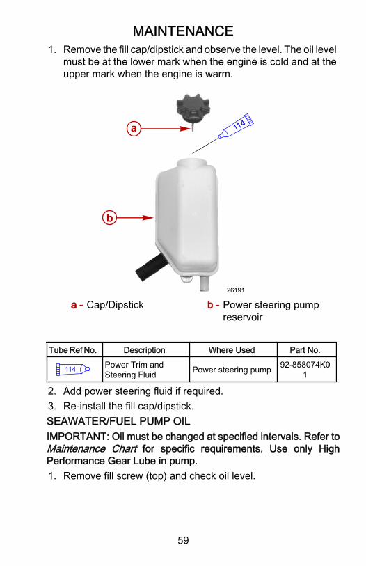
MAINTENANCE
59
1. Remove the fill cap/dipstick and observe the level. The oil levelmust be at the lower mark when the engine is cold and at theupper mark when the engine is warm.
114
26191
a
b
a - Cap/Dipstick b - Power steering pumpreservoir
Tube Ref No. Description Where Used Part No.
114 Power Trim andSteering Fluid Power steering pump 92-858074K0
1
2. Add power steering fluid if required.3. Re‑install the fill cap/dipstick.SEAWATER/FUEL PUMP OILIMPORTANT: Oil must be changed at specified intervals. Refer toMaintenance Chart for specific requirements. Use only HighPerformance Gear Lube in pump.1. Remove fill screw (top) and check oil level.

MAINTENANCE
60
2. Oil must come up to fill hole. If oil level is low, contact yourauthorized Mercury MerCruiser dealer for appropriate service.Do not operate engine if this oil level is low.
a
7901
a - Fill screw
Tube Ref No. Description Where Used Part No.
87 High PerformanceGear Lubricant Seawater/fuel pump 92-858064K0
1
ENGINE COOLANT
! CAUTIONA sudden loss of pressure can cause hot coolant to boil anddischarge violently resulting in serious injury from burns. Allowthe engine to cool down before removing the coolant pressurecap.

MAINTENANCE
61
IMPORTANT: Check engine coolant before starting engine.1. Check coolant level in coolant reservoir. Coolant should be at
the full line marked on the reservoir with the engine cold. Addspecified coolant as required.
a
19621
a - Coolant reservoir cap
2. If coolant is low,inspect coolant recovery system for leaks.3. Inspect the cap for damage and replace if necessary.CHECKING POWER TRIM PUMP FLUIDIMPORTANT: Check oil level with sterndrive unit in the full down/in position.1. Place the sterndrive unit in the full down/in position.2. Check the fluid level in the trim pump reservoir. The level
should be between the "MIN" and "MAX" level marks on thereservoir.

MAINTENANCE
62
3. If necessary, remove the fill cap and add Power Trim andSteering Fluid until the level in the reservoir reaches the "MIN"level mark. It is acceptable to fill the reservoir beyond the"MIN" level mark, but do not overfill past the "MAX" level mark.
114
15033
Tube Ref No. Description Where Used Part No.
114 Power Trim andSteering Fluid Trim pump reservoir 92-858074K0
1
4. Raise the sterndrive unit two or three times to bleed air out ofthe system. The fluid level may drop. Add more Power Trimand Steering Fluid if necessary, but do not overfill past the"MAX" level mark.
5. Replace the fill cap.CHECKING TRANSOM INPUT SHAFT BEARING HOUSING(DRIVE-LINE MODELS ONLY)1. Remove the level indication (middle) pipe plug from the input
shaft housing. Gear lube level should be to the bottom of thehole. If not, remove the pipe plug from the top of the input shafthousing.
2. Fill the input shaft housing through the top pipe plug hole withHigh Performance Gear Lube until gear lube flows from themiddle pipe plug hole (do not overfill).

MAINTENANCE
63
3. Install the pipe plugs into the input shaft housing and tightensecurely.
a
b
c 21730
a - Fill holeb - Check level herec - Drain
Tube Ref No. Description Where Used Part No.
87 High PerformanceGear Lubricant
Transom input shaftbearing housing 92-858064K01
CHECKING NXT¹ DRIVE UNIT GEAR LUBE1. Remove the upper vent plug from the gearcase. The gear lube
level should be to the bottom of the vent plug hole with thepropeller shaft level.
2. If gear lube level is low, add High Performance Gear Lube untilgear lube comes out of the vent plug opening.

MAINTENANCE
64
3. Install the vent plug.
a
b 21707
a - Vent plug opening b - Level propeller shaft
Tube Ref No. Description Where Used Part No.
87 High PerformanceGear Lubricant Drive uinit 92-858064K01
CHECKING SIX DRIVE UNIT GEAR LUBE1. Remove the upper vent plug from the gearcase. The gear lube
level should be to the bottom of the vent plug hole with thepropeller shaft level.
2. If gear lube level is low, add Torco MTF Gear Lube until gearlube comes out of the vent plug opening.

MAINTENANCE
65
3. Install the vent plug.
7429
a
b 150
a - Vent Plugb - Fill/Drain Plug
Tube Ref No. Description Where Used Part No.
150 Torco MTF Gear Oil VI Drive GearHousing 92-849684 1
CHECKING TRANSMISSION FLUID LEVELIMPORTANT: Wait at least 30 minutes before checking thetransmission fluid level to avoid inaccurate readings.1. Remove the transmission dipstick and check the fluid level.
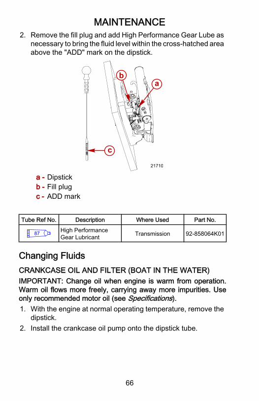
MAINTENANCE
66
2. Remove the fill plug and add High Performance Gear Lube asnecessary to bring the fluid level within the cross‑hatched areaabove the "ADD" mark on the dipstick.
ab
21710
c
a - Dipstickb - Fill plugc - ADD mark
Tube Ref No. Description Where Used Part No.
87 High PerformanceGear Lubricant Transmission 92-858064K01
Changing FluidsCRANKCASE OIL AND FILTER (BOAT IN THE WATER)IMPORTANT: Change oil when engine is warm from operation.Warm oil flows more freely, carrying away more impurities. Useonly recommended motor oil (see Specifications).1. With the engine at normal operating temperature, remove the
dipstick.2. Install the crankcase oil pump onto the dipstick tube.
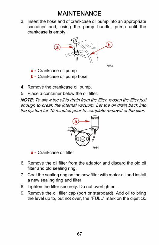
MAINTENANCE
67
3. Insert the hose end of crankcase oil pump into an appropriatecontainer and, using the pump handle, pump until thecrankcase is empty.
ba
7983
a - Crankcase oil pumpb - Crankcase oil pump hose
4. Remove the crankcase oil pump.5. Place a container below the oil filter.NOTE: To allow the oil to drain from the filter, loosen the filter justenough to break the internal vacuum. Let the oil drain back intothe system for 15 minutes prior to complete removal of the filter.
a
7984
a - Crankcase oil filter
6. Remove the oil filter from the adaptor and discard the old oilfilter and old sealing ring.
7. Coat the sealing ring on the new filter with motor oil and installa new sealing ring and filter.
8. Tighten the filter securely. Do not overtighten.9. Remove the oil filler cap (port or starboard). Add oil to bring
the level up to, but not over, the "FULL" mark on the dipstick.

MAINTENANCE
68
IMPORTANT: Always use the dipstick to determine exactly howmuch oil is required.
a 7899
79
a - Crankcase oil filler cap
Tube Ref No. Description Where Used Part No.
79 MerCruiser 4-cycle25W40 Engine Oil Engine crankcase 92-858048K0
1
CRANKCASE OIL AND FILTER (BOAT OUT OF THE WATER)
! WARNINGPerforming tests with the engine running may cause the propellerto rotate and result in serious injury or death. Use caution whenperforming a test that requires the engine running, and removethe propeller to avoid injury.
NOTICEOperating the engine out of the water at high speeds createssuction, which can collapse the water supply hose and overheatthe engine. Do not operate the engine above 1400 RPM out ofthe water and without sufficient cooling water supply.
IMPORTANT: Change oil when the engine is warm from operation.Warm oil flows more freely, carrying away more impurities. UseMercury Precision Parts or flushing attachment(s) over the waterintake holes and attach a water hose. Use only recommendedmotor oil, see Specifications.1. Provide cooling water to the engine (see Flushing the
Cooling System in this section).

MAINTENANCE
69
2. Place the remote control in the neutral position and start theengine. Operate the engine at idle speed, in neutral, until theengine reaches normal operating temperature.
3. Stop the engine, shut off the water, and remove the flushingattachment(s).
4. Remove the bilge plug. The oil drain hose is tethered to theplug.
6150
ed
cb
a
a - Bilge drain plugb - Tetherc - Oil drain plug
d - Bilge drain flangee - Oil drain hose
5. Pull the oil drain hose through the bilge drain flange.6. Place an appropriate container directly under the oil drain
hose.7. Using two wrenches, separate the oil drain hose plug from the
oil drain hose and allow the crankcase oil to drain until empty.8. Place a container below the oil filter.NOTE: To allow the oil to drain from the filter, loosen the filterenough to break the internal vacuum . Let the oil drain back intothe system for 15 minutes prior to complete removal of the filter.9. Remove the oil filter from the adaptor and discard old oil filter
and the old sealing ring.10.Coat the sealing ring on new the filter with motor oil. Install the
new sealing ring and filter. Tighten the filter securely. Do notovertighten.
11.Using two wrenches, connect the oil drain hose plug to the oildrain hose and place back into the boat.
12.Tighten the bilge drain plug.13.Remove oil filler cap (port or starboard). Add oil to bring the
level up to, but not over, the "FULL" mark on the dipstick.

MAINTENANCE
70
IMPORTANT: Always use the dipstick to determine exactly howmuch oil is required.
a 7899
79
a - Crankcase oil filler cap
Tube Ref No. Description Where Used Part No.
79 MerCruiser 4-cycle25W40 Engine Oil Engine crankcase 92-858048K0
1
TRANSMISSION, AND DRIVE FLUIDSChanging Transmission Oil1. Remove the bilge plug and pull the drain hose through the
transom.2. Using two wrenches, separate the drain plug from the hose.
6150
ed
cb
a
a - Bilge plugb - Tetherc - Drain plug
d - Flangee - Drain hose
3. Reinstall the drain and bilge plug after draining the fluid.

MAINTENANCE
71
4. Remove the fill plug and add High Performance Gear Lube asnecessary to bring the fluid level within the cross‑hatched areaabove the "ADD" mark on the dipstick (approximately 1 Liter(1.1 U.S. quarts).
ab
21710
c
a - Dipstickb - Fill plugc - "ADD" mark
Tube Ref No. Description Where Used Part No.
87 High PerformanceGear Lubricant Transmission 92-858064K01
Capacity Fluid TypeTransmission 1 Liter (1.1 Qts.) High Performance Gear Lubricant

MAINTENANCE
72
Changing NXT¹ Drive Unit Gear Lube1. Remove propeller, position drive unit so propeller shaft is
level.
21733
a
ba - Oil level hole b - Level
2. Remove the water pick‑up.
a
a
a
a
b
21209
a - Fasteners b - Water pick‑up
3. Remove the tab washer.4. Remove fill/drain screw and vent screw from gear housing and
drain the gear lube.

MAINTENANCE
73
IMPORTANT: If any water drained, or if gear lube appears milky,the drive unit is leaking and should be checked immediately byyour authorized Mercury MerCruiser Dealer.
21210
a
ba - Tab washer b - Fill/drain screw
5. Fill the drive unit, through the fill/drain hole, with HighPerformance Gear Lube until a stream of lubricant flows fromgear oil level hole.

MAINTENANCE
74
6. Install vent screw and remove tube from fill/drain hole. Quicklyinstall the fill/drain screw. Tighten securely.
21733
a
ba - Oil level hole b - Level
7. Install tab washer.
21210
a
ba - Tab washer b - Fill/drain screw

MAINTENANCE
75
8. Install water pick‑up and tighten fasteners to specification.
a
a
a
a
b
21209
a - Fasteners b - Water pick‑up
Description Nm lb. in. lb. ft.Water pick‑up fasteners 3.4 30
9. Install propeller.10.Check oil level after first test trial. Refill if necessary.Changing Six Drive Unit Gear LubeIMPORTANT: Use only Torco MTF Gear Oil in the drive unit.1. Remove the propeller and place the drive unit where the
propeller shaft is level.2. Remove the fill/drain screw, sealing washer, vent screw, and
sealing washer from the gear housing.IMPORTANT: If any water drained, or if gear lube appears milky,the drive unit is leaking and should be checked immediately byyour authorized Mercury MerCruiser Dealer.

MAINTENANCE
76
3. Fill the drive unit through the fill/drain hole with Torco MTFGear Oil until an air‑free stream of lubricant flows from thegear oil level hole of gear housing.
7429
a
b 150
a - Top vent screwb - Fill/drain screw
Tube Ref No. Description Where Used Part No.
150 Torco MTF Gear Oil VI Drive gear housing 92-849684 1
IMPORTANT: If the filter was replaced, rotate the propeller shaftat least 80 full revolutions to fill the filter cavity with oil. Recheckthe fluid level and add fluid as necessary.4. Install vent screw and washer and remove tube from fill/drain
hole. Quickly install the sealing washer and the fill/drain screw.Tighten securely.
5. Check oil level after first test trial. Add fluid if necessary.Changing Transom Input Shaft Bearing Housing Gear Lube (Drive‑lineModels)1. Remove the drain plug and drain the oil.2. Install the drain plug and tighten securely.3. Remove the plug from the fill hole.4. Remove the plug from the fill level hole.

MAINTENANCE
77
5. Pour High Performance Gear lube into the fill hole until fluidstarts to come from the fill level hole.
6. Install both plugs and tighten securely.7. a
b
c 21730
a - Fill holeb - Fill levelc - Drain
LubricationLubricate the following grease fittings with Optimal PD‑2:• Engine driveshaft.• Transmission shift lever ‑ Lubricate poppet ball.Lubricate pivot points with SAE 25W40 motor oil:• Shift cable.

MAINTENANCE
78
• Throttle linkage and cable ‑ Lubricate cable and swivels.
F - N - R
7446
79 79
145145
Tube Ref No. Description Where Used Part No.
145Optimal Longtime PD2Extreme PressureGrease
Engine drive shaft andtransmission shift lever 92-848767
Tube Ref No. Description Where Used Part No.
79 MerCruiser 4-cycle25W40 Engine Oil
Shift cable and throttlelinkage 92-858048K01
Maximus Propeller Installation (NXT¹)IMPORTANT: Ensure that the propeller direction of rotationmatches the propeller shaft direction of rotation.

MAINTENANCE
79
! WARNINGRotating propellers can cause serious injury or death. Neveroperate the boat out of the water with a propeller installed. Beforeinstalling or removing a propeller, place the drive unit in neutraland engage the lanyard stop switch to prevent the engine fromstarting. Place a block of wood between the propeller blade andthe anti‑ventilation plate.
IMPORTANT: Propeller damage can occur if there is not enoughspace between the propeller tips. Multi‑engine configurationsrequire a minimum distance of 25.4 mm (1 in.) gap betweenpropeller tips to prevent damage to the propellers and otherequipment.
a bc
d e
f
g
21708
a - Nutb - Washerc - Belleville Washerd - Spacer
e - Propeller Hubf - Bushing (factory installed
in the propeller hub)g - Retaining ring (factory
installed in the propellerhub)
Tube Ref No. Description Where Used Part No.
94 Anti-Corrosion Grease Propeller shaft splines 92-802867Q 1
1. Coat the propeller shaft splines with Anti‑Corrosion Grease.
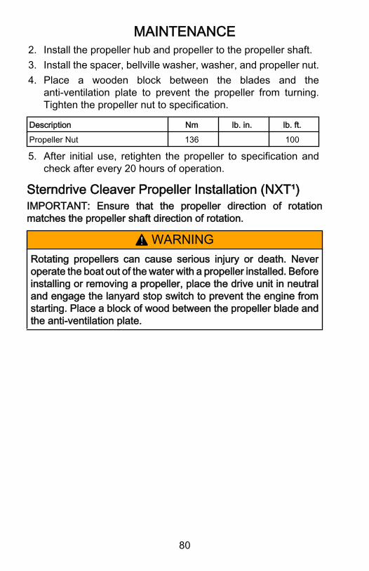
MAINTENANCE
80
2. Install the propeller hub and propeller to the propeller shaft.3. Install the spacer, bellville washer, washer, and propeller nut.4. Place a wooden block between the blades and the
anti‑ventilation plate to prevent the propeller from turning.Tighten the propeller nut to specification.
Description Nm lb. in. lb. ft.Propeller Nut 136 100
5. After initial use, retighten the propeller to specification andcheck after every 20 hours of operation.
Sterndrive Cleaver Propeller Installation (NXT¹)IMPORTANT: Ensure that the propeller direction of rotationmatches the propeller shaft direction of rotation.
! WARNINGRotating propellers can cause serious injury or death. Neveroperate the boat out of the water with a propeller installed. Beforeinstalling or removing a propeller, place the drive unit in neutraland engage the lanyard stop switch to prevent the engine fromstarting. Place a block of wood between the propeller blade andthe anti‑ventilation plate.

MAINTENANCE
81
IMPORTANT: Propeller damage can occur if there is not enoughspace between the propeller tips. Multi‑engine configurationsrequire a minimum distance of 25.4 mm (1 in.) gap betweenpropeller tips to prevent damage to the propellers and otherequipment.
ac
d
e
f
21685
b
a - Nylon Nutb - Jam nutc - Washer
d - Adaptor (Mercury Racingsterndrive cleaverpropeller)
e - Bushingf - Retaining ring
1. Install the adaptor into the propeller, as shown.
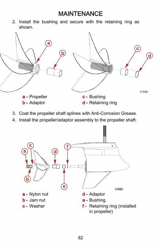
MAINTENANCE
82
2. Install the bushing and secure with the retaining ring asshown.
a
bc
d
21686
a - Propellerb - Adaptor
c - Bushingd - Retaining ring
3. Coat the propeller shaft splines with Anti‑Corrosion Grease.4. Install the propeller/adaptor assembly to the propeller shaft.
ac
d
e
f
21685
b
a - Nylon nutb - Jam nutc - Washer
d - Adaptore - Bushingf - Retaining ring (installed
in propeller)

MAINTENANCE
83
Tube Ref No. Description Where Used Part No.
94 Anti-CorrosionGrease
Propeller shaftsplines
92-802867Q1
5. Place a wooden block between the blades and theanti‑ventilation plate to prevent the propeller from turning.Tighten the jam nut to specification and install the nylon nutand tighten to specification.
Description Nm lb. in. lb. ft.Nylon nut, Jam nut 136 100
6. After initial use, retighten the propeller to specification andcheck after every 20 hours of operation.
Cleaver Propeller Installation (SSM)1. Lubricate the propeller shaft splines with a specified grease.2. Install the propeller onto the shaft.3. Install the washer.4. Install the propeller nut and tighten to the specified torque.

MAINTENANCE
84
NOTICEImproper installation can cause gear housing damage. Alwaysuse a new propeller bushing when installing the propeller on aIIIa, IV, or V SSM Drive.
a
b
c
d
16141
a - Plastic bushingretainer
b - Plastic bushing
c - Washerd - Prop nut
Tube Ref No. Description Where Used Part No.
94 Anti-CorrosionGrease
Propeller Shaftsplines
92-802867Q1
Description Nm lb. in. lb. ft.Propeller nut 136 100

MAINTENANCE
85
Flushing Cooling System
! WARNINGRotating propellers can cause serious injury or death. Neveroperate the boat out of the water with a propeller installed. Beforeinstalling or removing a propeller, place the drive unit in neutraland engage the lanyard stop switch to prevent the engine fromstarting. Place a block of wood between the propeller blade andthe anti‑ventilation plate.
NOTICEOperating the engine out of the water at high speeds createssuction, which can collapse the water supply hose and overheatthe engine. Do not operate the engine above 1400 RPM out ofthe water and without sufficient cooling water supply.
NOTE: To prevent silt and/or salt buildup in cooling system, flushwith freshwater at specified intervals.1. Disconnect water inlet hose from seawater pickup pump and
install flushing hose from water tap to seawater pickup pumpconnector.
2. With drive unit in normal operating position, partially openwater tap (about 1/2 maximum).
3. Place remote control in neutral position, and start engine.Operate engine at idle speed, in neutral, for about 10 minutesor until discharge water is clear.
4. Stop engine, shut off water, and remove flushing attachment.5. Re‑install water inlet hose to seawater pickup pump.
Seawater Pump Impeller InspectionService should be performed by an authorized Mercury MerCruiserdealer.

MAINTENANCE
86
1. Inspect seawater pump impeller if insufficient seawater flowoccurs (if operating temperature exceeds normal range).
a8022
a - Seawater pump
Cleaning Seawater (Raw Water) Section of theCoolers
NOTICEAn open seawater strainer or seacock during some service ormaintenance procedures can introduce water into the boat,causing damage or sinking the boat. Always close the watersupply from the seawater pump, water inlet, or seacock whenperforming service or maintenance on the cooling system.
The seawater section of oil cooler should be cleaned at least oncea year or whenever decreased cooling efficiency is noticed.ENGINE OIL COOLERNOTE: The engine oil cooler is located on the top rear portion ofthe engine.1. Remove end plates and gaskets.
aa
8030
a - End plates (2)
2. Clean oil cooler with a suitable brush.

MAINTENANCE
87
3. Flush passages with fresh water.4. Inspect gaskets for deterioration and replace if necessary.5. Install gaskets and end plates. Tighten screws securely.POWER STEERING COOLERNOTE: The power steering cooler is located on the lower port sideof the engine.1. Loosen water hose clamps and remove hoses if it is necessary
to inspect or clean cooler.IMPORTANT: If the oil hoses need to be removed from the cooler,be prepared to cap or plug them to avoid draining the powersteering reservoir.
a
a
8031
a - Hose clamps (2)
2. Re‑install cooler and tighten hose clamps securely.3. Check power steering fluid level.4. Start engine and inspect cooling system for leaks.TRANSMISSION COOLERNOTE: The transmission cooler is located on the lower rear portside of the engine, next to the flywheel.

MAINTENANCE
88
1. Loosen the hose clamps and remove the water hoses toinspect and clean the cooler.
16936bc
a
dd
bb
a - Power steering coolerb - Hose clamps
c - Transmission coolerd - Engine oil cooler
2. Clean the oil cooler with a suitable brush.3. Flush the cooler with fresh water.4. Drain the water from the cooler and hoses completely.5. Install the hoses and clamps. Tighten the screws securely.
Changing Positive Crankcase Ventilation ValveThis engine is equipped with a positive crankcase ventilation valve(PCV). This valve should be changed every 100 hours of operationor at least once a year, whichever occurs first.• Pull valve out of intake manifold and remove valve from hose.• Install new PCV valve into hose, and install into intake
manifold.• Ensure that the valve is tightly seated in manifold.Use only Mercury MerCruiser replacement parts.
MAINTENANCE
89
Serpentine Drive BeltDRIVE BELT ROUTING AND TENSION
! WARNINGInspecting the belts with the engine running may cause seriousinjury or death. Turn off the engine and remove the ignition keybefore adjusting tension or inspecting belts.
IMPORTANT: Drive belt must be routed as shown or damage mayresult.1. Loosen the 5/8 in locking nut on adjustment stud. Leave the
wrench on the adjustment nut.2. Install the belt tension gauge onto the belt.3. Use a 5/16 in socket and tighten adjusting stud until the belt
tension conforms to the correct setting on the gauge.4. Hold the adjustment stud and tighten the 5/8 in locking nut.5. Remove the belt tension gauge from the belt.

MAINTENANCE
90
6. Run the engine for a short period of time and re‑check tension.
c
b
a
g
f
ed
6163
a - Crankshaft pulleyb - Circulating pump
pulleyc - Alternator pulleyd - Power steering pulley
(Non‑power steeringmodels have an idlerpulley)
e - Idler pumpf - Seawater pump pulleyg - Belt tension gauge
Description N lb.New Belt 489 110Used Belt 400 90
INSPECTING BELTNOTE: Minor, transverse cracks (across the belt width) may beacceptable. Longitudinal cracks (in the direction of belt length) thatjoin transverse cracks are not acceptable.The belt will have to be replaced for the following conditions:

MAINTENANCE
91
• Excessive wear• Cracks or fraying• Glazed surfaces
a
c
b
6164
a - Frayingb - Transverse cracksc - Longitudinal cracks
Changing Fuel FiltersWATER SEPARATING FUEL FILTER
! WARNINGFuel is flammable and explosive. Ensure the key switch is off andthe lanyard is positioned so that the engine cannot start. Do notsmoke or allow sources of spark or open flame in the area whileservicing. Keep the work area well ventilated and avoidprolonged exposure to vapors. Always check for leaks beforeattempting to start the engine and wipe up any spilled fuelimmediately.

MAINTENANCE
92
1. Remove the water separating fuel filter and sealing ring frommounting bracket and discard.
b
c
a
6152
a - Water separating fuel filterb - Sealing ringc - Mounting bracket
2. Coat the sealing ring on new filter with motor oil.IMPORTANT: Do not use a filter wrench to tighten the filter.3. Thread the filter onto the bracket and tighten securely by hand.4. Start and run engine. If the engine stops or will not start, it may
be necessary to prime the fuel system (see Priming the FuelSystem Prior to Starting in the Cold Weather or ExtendedStorage section of this manual).
5. Check the filter connection for fuel leaks. If leaks exist,recheck the filter installation.
6. If leaks continue, stop the engine immediately and contactyour authorized Mercury MerCruiser dealer.

MAINTENANCE
93
FUEL FILTER ELEMENT1. Remove the fuel line from the filter head.
18962
a
b
c
a - Fuel filter headb - Fuel line
c - Fuel filter element
2. Turn the filter head and remove.3. Remove the internal filter element.4. Insert the new filter element.5. Install the filter head.6. Install the fuel line.7. Start the engine and check for leaks.
Corrosion and Corrosion ProtectionWhenever two or more dissimilar metals (like those found on thesterndrive) are submerged in a conductive solution, such assaltwater, polluted water, or water with a high mineral content, achemical reaction takes place causing electrical current to flowbetween metals. The electrical current flow causes the metal thatis most chemically active, or anodic, to erode. This is known asgalvanic corrosion and, if not controlled, it will in time cause theneed for replacement of power package components exposed towater.Refer to the Quicksilver booklet, Everything You Need to KnowAbout Marine Corrosion for more corrosion information.

MAINTENANCE
94
NOTICEUsing magnesium anodes in salt water causes anelectrochemical reaction on the metal surface of the drive,resulting in corrosion damage from the paint blistering andpeeling off the drive. Use magnesium anodes in fresh water only.
IMPORTANT: If a boat is equipped with stainless steel afterplanes, a large anode should be installed on each to handle theincreased galvanic corrosion potential.Replace sacrificial anodes if eroded 50% or more.Mercury Marine recommends using anodes sold through MercuryPrecision Parts only. Some other manufacturers of aluminumanodes use alloys that are insufficiently pure to adequately protectcritical drive components for the duration of the anodes' expectedlife.
a b
22214
a - Transom anode b - Drive anode
In addition to the corrosion protection devices, follow these stepsto inhibit corrosion:1. Painting Boat Hull or Boat Transom
a. If anti‑fouling protection is required for boat hull or boattransom, copper or tin base paints can be used unlessotherwise prohibited by law.

MAINTENANCE
95
b. If using copper or tin based anti‑fouling paints, avoid anyelectrical interconnection between the Mercury MarineProduct, anodic blocks, and the paint by allowing aminimum of 40 mm (1.5 in.) unpainted area on the transomof the boat around these items.
a b6118
a - Anti‑fouling paintb - Unpainted area
IMPORTANT: Corrosion damage that results from the improperapplication of anti‑fouling paint will not be covered by the limitedwarranty.NOTE: Do not paint anodes. Painting anodes will render themineffective as galvanic corrosion inhibitors.2. Painting Drive Unit or Transom Assembly
MAINTENANCE
96
• Paint the drive unit and transom assembly with a goodquality marine paint or an anti‑fouling paint that does notcontain copper, tin, or any other material that could conductelectrical current. Do not paint drain holes, anodes, or itemsspecified by the boat manufacturer.
3. Additional Corrosion Prevention Tips• Spray the power package components on the inside of the
boat every two to three weeks with Corrosion Guard toprotect the finish from dulling and corrosion. Externalpower package components may also be sprayed.
Tube Ref No. Description Where Used Part No.
120 Corrosion Guard Power package 92-802878 55
• All lubrication points, especially the steering system andshift and throttle linkages, should be kept well lubricated.
• Flush the raw water portion of the cooling system after eachuse.
MERCATHODETo protect the larger sterndrive engine packages from galvaniccorrosion, purchase this MerCathode kit, (PN 42600A18).Galvanic IsoltaorsLow‑voltage galvanic current can be passed between neighboringboats through the shore‑power electrical transmission lines.Galvanic isolators block this low voltage current that can destroyyour power package. Ensure that the isolator is of high quality, andrated to handle the amperage load of the boat and the shore‑powerconnected to it.
BatteryAll lead acid batteries discharge when not in use. Recharge every30 to 45 days, or when specific gravity drops below batterymanufacturer's specifications.Refer to specific instructions and warnings accompanying yourbattery. If this information is not available, observe the following:

MAINTENANCE
97
! WARNINGAn operating or charging battery produces gas that can ignite andexplode, spraying out sulfuric acid, which can cause severeburns. Ventilate the area around the battery and wear protectiveequipment when handling or servicing batteries.
! WARNINGRecharging a weak battery in the boat, or using jumper cablesand a booster battery to start the engine, can cause serious injuryor product damage from fire or explosion. Remove the batteryfrom the boat and recharge in a ventilated area away from sparksor flames.
Bottom of BoatTo maintain maximum speed, ensure that the boat bottom is:• Clean, free of barnacles and marine growth.• Free of distortion, nearly flat where it contacts water.• Straight and smooth, fore and aft.Marine vegetation may accumulate when the boat is docked. Thisgrowth must be removed before operation; it may clog water inletsand cause the engine to overheat.
Inspection and MaintenanceInspect the power package often and at regular intervals to helpmaintain its top operating performance, and correct potentialproblems before they occur. The entire power package should bechecked carefully, including all accessible engine parts.1. Check for loose, damaged or missing parts, hoses and
clamps; tighten or replace as required.2. Check plug leads and electrical leads for damage.3. Remove and inspect the propeller. If nicked, bent or cracked,
see your authorized Mercury Marine dealer.4. Repair nicks and corrosion damage on the power package's
exterior finish. Use Quicksilver spray paints ‑ see yourauthorized Mercury Marine dealer.

MAINTENANCE
98
Attention Required After Submersion• Before recovery, contact an authorized Mercury Marine
dealer.• After recovery, immediate service by an authorized Mercury
Marine dealer is required to prevent serious damage to powerpackage.

COLD WEATHER OR EXTENDED STORAGE
99
Power Package Lay‑upIMPORTANT: This service should be performed by an authorizedMercury Marine dealer.
NOTICEWithout sufficient cooling water, the engine, the water pump, andother components will overheat and suffer damage. Provide asufficient supply of water to the water inlets during operation.
IMPORTANT: Before starting the engine, attach a water source tothe seawater pickup pump. Follow all warnings and flushingattachment procedures stated in the Flushing Cooling Systemsection of this manual.Refer to Flushing Cooling System to prepare the engine forflushing. Cooling system flushing and the fuel system storageprocedures are performed together.
! WARNINGFuel vapors trapped in the engine compartment may be anirritant, cause difficulty breathing, or may ignite resulting in a fireor explosion. Always ventilate the engine compartment beforeservicing the power package.
Prepare the fuel system for extended storage by:1. Mixing the following in a 23 liter (6 U.S. gal) remote outboard
fuel tank:• 19 liter (5 U.S. gal) premium unleaded 92 octane (R+M)/2
(98 RON) gasoline.• 1.89 liter (64 fl oz) Premium Plus 2‑cycle TC‑W3 outboard
oil.• 150 ml (5 fl oz) Fuel System Treatment and Stabilizer or
30 ml (1 fl oz) Fuel System Treatment and StabilizerConcentrate.
2. Close the fuel shutoff valve located between the fuel tank andthe water separating fuel filter.
3. Disconnect and plug the boat's fuel line from the waterseparating fuel filter inlet.

COLD WEATHER OR EXTENDED STORAGE
100
4. Connect the remote outboard fuel tank to the inlet of the waterseparating fuel filter.
5. Have the engine ready for flushing as explained in theFlushing Cooling System section of this manual (coolingsystem flushing and the fuel system storage procedures areperformed together). Start and run the engine at 1000 RPMfor a minimum of five minutes or longer (if required) tocomplete the fuel system preperation and the cooling systemflushing.
6. After the specified running time is complete, slowly return thethrottle to idle RPM and shut off the engine.
IMPORTANT: Maintain an adequate supply of the fuel/foggingmixture in the remote 23 liter (6 U.S. gal) tank to complete the fuelsystem treatment and flushing procedure. Do not let the remotetank or fuel system run dry.7. If fuel in the main tank(s) contains alcohol, (if fuel without
alcohol is not available) drain the fuel tank(s) completely andadd Gasoline Stabilizer and Conditioner to any fuel remainingin the tank(s) before storage.
8. Close the fuel shut off valve, if equipped.9. Change the engine oil and oil filter.
NOTICEThe universal joint bellows may develop a set when stored in araised or up position, causing the bellows to fail when returnedto service and allowing water to enter the boat. Store thesterndrive in the full down position.
10.Place the drive unit in the full down position.

COLD WEATHER OR EXTENDED STORAGE
101
Engine Draining InstructionsNOTICE
Water trapped in the seawater section of the cooling system cancause corrosion or freeze damage. Drain the seawater sectionof the cooling system immediately after operation or before anylength of storage in freezing temperatures. If the boat is in thewater, keep the seacock closed until restarting the engine toprevent water from flowing back into the cooling system. If theboat is not fitted with a seacock, leave the water inlet hosedisconnected and plugged.
NOTE: As a precautionary measure, attach a tag to the key switchor steering wheel of the boat reminding the operator to open theseacock or unplug and reconnect the water inlet hose beforestarting the engine.IMPORTANT: The boat must be as level as possible to ensurecomplete draining of cooling system.1. Remove the following drain plugs:
• End of exhaust manifold balance rail (plastic wingnut plugs,port and starboard)
• Fuel cooler (plastic wingnut plug, below engine front)

COLD WEATHER OR EXTENDED STORAGE
102
• Bottom of power steering cooler (plastic wingnut plug)
a
b
d34957
c
a - Exhaust manifold balance rail wingnutb - Transmission luid coolerc - Fuel cooler wingnutd - Power steering cooler wingnut
2. Repeatedly clean out drain holes using a stiff piece of wire.Do this until entire system is drained.
3. Loosen hose clamp and remove the hose from inlet fitting ofseawater pickup pump.

COLD WEATHER OR EXTENDED STORAGE
103
NOTE: Lift or bend hoses to allow water to drain completely.a
8040
a - Hose clamp
4. After draining seawater cooling system, install drain plugs(Perfect Seal is not required on wing nut type plugs),reconnect hoses and tighten all hose clamps securely.
5. Make sure the following passages are open and unobstructed:
12893a
a - Speedometer pitot tubeb - Trim tab cavity vent holec - Trim tab cavity drain passage
6. For additional assurance against freezing and rust in theengine seawater cooling system when storing for winter orlong periods of non use, perform the following steps:

COLD WEATHER OR EXTENDED STORAGE
104
IMPORTANT: A nontoxic and environmentally safe ethyleneglycol antifreeze containing a rust inhibitor must be used whenpreparing the seawater section of the cooling system for coldweather or extended storage. Be certain to follow themanufacturer's recommendations.NOTE: If the boat is in the water during the following procedure,the seawater shut off valve must be closed and the hose removedfrom the engine side of the valve to avoid water entering the boat.
a. Remove seawater inlet hose leading to the seawater pumpand place the hose into a container of ethylene glycolantifreeze to protect engine to the lowest temperature towhich it will be exposed during cold weather or extendedstorage.
ab
c
d
13180
efa - Seawater shut off valveb - Disconnect hose here and place into container of
antifreezec - To the seawater pump
b. Operate engine at idle until antifreeze is expelled from theexhaust manifolds of the engine.
c. Stop the engine and reconnect the pickup hose.7. Perform all checks, inspections, lubrication, and fluid changes
outlined in the Maintenance Chart under at least once a year.
Battery Winter StorageFollow the battery manufacturer's instructions for storage.

COLD WEATHER OR EXTENDED STORAGE
105
Power Package RecommissioningIMPORTANT: Do not install the battery until all enginemaintenance is completed.1. Ensure that all cooling system hoses are connected properly
and hose clamps are tight, all removed drain plugs have beeninstalled and are tight.
! CAUTIONDisconnecting or connecting the battery cables in the incorrectorder can cause injury from electrical shock or can damage theelectrical system. Always disconnect the negative (‑) batterycable first and connect it last.
2. Install fully‑charged battery. Clean battery cable clamps andterminals and reconnect cables. Tighten each cable clampsecurely when connecting.
3. Coat battery terminal connections with a anti‑corrosion agent.4. Perform all checks in Operation Chart in the Before
Starting column.5. Refer to Flushing Cooling System before starting engine.6. Supply water to engine cooling system.STARTING WITHOUT PRIMING THE FUEL SYSTEMIMPORTANT: The throttle must not be advanced until the engineidles and runs smoothly and the water temperature reaches aminimum of 54 °C (130 °F). Advancing the throttle prematurelywhile the PCM is in its rich running mode will result in poor enginestarting and performance.1. Connect the main permanent fuel line to the engine.2. Do not advance the throttle until the engine idles and runs
smoothly and the water temperature reaches a minimum of 54°C (130 °F).
3. Crank the engine over for 10 seconds at a time and stop.4. Repeat cranking procedure until the engine starts and runs
smoothly. Observe instrumentation to insure all systems arefunctioning.
5. Inspect engine for fuel, oil, fluid, water and exhaust leaks.

COLD WEATHER OR EXTENDED STORAGE
106
6. Check steering system, shift and throttle control for properoperation.
PRIMING THE FUEL SYSTEM PRIOR TO STARTING
! WARNINGFuel is flammable and explosive. Ensure the key switch is off andthe lanyard is positioned so that the engine cannot start. Do notsmoke or allow sources of spark or open flame in the area whileservicing. Keep the work area well ventilated and avoidprolonged exposure to vapors. Always check for leaks beforeattempting to start the engine and wipe up any spilled fuelimmediately.
1. Remove the plug from the water separating fuel filter as shownfollowing and install a barbed fitting into the water separatingfuel filter.
ab
6166
a - Water seperating fuel filter plugb - Barbed fitting
2. Attach an outboard type portable fuel tank with primer bulb tothe barbed fitting with a hose clamp.
3. Squeeze the primer bulb until the bulb becomes firm.NOTE: Do not turn the key switch to the "START" position duringthe following priming procedure.

COLD WEATHER OR EXTENDED STORAGE
107
4. Cycle the ignition key switch to the "RUN" position for threeseconds and then "OFF."
5. Repeat steps three and four, one to two more times. Theobject of this procedure is to prime the fuel system but not tothe point of having the system completely full and the primerbulb hard and under pressure.
6. With the primer bulb soft, remove the remote fuel line andfitting from the water separating fuel filter.
! WARNINGIf the primer bulb is hard when removing the remote fuel tank,pressurized fuel will be sprayed in the engine compartmentcreating an explosive condition that could result in serious injuryor death. When removing the remote fuel tank line from theengine connection, ensure that the primer bulb is soft.
7. Re‑install the plug in the water separating fuel filter usingLoctite Pipe Sealant with Teflon on the threads.
8. Attempt to start the engine by turning the key switch to the"START" position for a maximum of 15 seconds or until theengine starts and runs smoothly. Do not advance the throttleuntil the water temperature has reached a minimum of 54 °C(130 °F).
IMPORTANT: The throttle must not be advanced until the engineidles and runs smoothly and the water temperature has reacheda minimum of 54 °C (130 °F). Advancing the throttle prematurelywhile the ECM is in its rich running mode will result in poor enginestarting and performance.9. Inspect engine for fuel, oil, fluid, water and exhaust leaks.10.Check steering system, shift and throttle control for proper
operation.

TROUBLESHOOTING
108
Engine Will Not CrankPossible Causes Remedy
Battery switch turned "OFF." Turn switch "ON."Gearshift not in neutral position. Position control lever to neutral.
Open circuit breaker or blown fuse. Check and reset circuit breaker orreplace fuse.
Loose or dirty electrical connections ordamaged wiring.
Check all electrical connections andwires (especially battery cables). Cleanand tighten faulty connection.
Defective battery. Test and replace if defective.Defective starter. Test and replace if defective.
Flywheel ring gear is damaged. Confirm diagnostic and replaceflywheel.
Engine is seized.Check to see if engine can be rotatedby hand with the spark plugs removed.If not, then determine cause.
Faulty ignition switch. Test wire with a remote starter switchat the starter motor.

TROUBLESHOOTING
109
Engine Cranks But Will Not StartPossible Cause Remedy
Improper starting procedure Read starting procedureLow battery voltage Charge the batteryEmpty fuel tank or fuel shut off valveclosed Fill tank or open valve
Faulty fuel pump, wiring, fuel pumpfuse, 50 amp circuit breaker or a fuelpump relay
Replace faulty component
Faulty ignition system component Service ignition systemLanyard Stop Activated ResetObstructed fuel filter Replace filters
Stale or contaminated fuel If contaminated, drain tank and fill withfresh fuel
Fuel line or tank vent line kinked orrestricted
Replace kinked lines or blow out lineswith compressed air to removeobstruction
Crankshaft position sensor faulty Test and replace if faulty
Faulty fuel pressure regulatordiaphragm
Test and replace if faulty. Do notattempt to start the engine if the fuelpressure regulator diaphragm isruptured.
Engine Hard to Start, Runs Rough, Misses, and/orBackfires
Possible Cause RemedyFaulty ignition system component. Service ignition system.Clogged fuel filter. Replace filters.
Stale or contaminated fuel. If contaminated, drain tank. Fill withfresh fuel.
Kinked or clogged fuel line or fuel tankvent line.
Replace kinked lines or blow outlines with compressed air to removeobstruction.
Flame arrestor plugged. Clean or replace the flame arrestor.Rev limiter engaging atwide‑open‑throttle. Change to propeller with more pitch.

TROUBLESHOOTING
110
Low Engine Coolant (Closed Cooling) TemperaturePossible Cause Remedy
Faulty thermostat. Replace.
Poor PerformancePossible Cause Remedy
Throttle not fully open. Inspect throttle cable and linkages forproper operation.
Damaged or wrong propeller. Replace propeller.Excessive bilge water. Drain and check for cause of entry.Boat overloaded or load improperlydistributed.
Reduce load or redistribute load moreevenly.
Boat bottom fouled or damaged. Clean or repair as necessary.Flame arrestor dirty. Change or clean flame arrestor.
Insufficient Engine TemperaturePossible Cause Remedy
Faulty water thermostat. Replace water thermostat.Faulty gauge or sender. Test with shop gauge; test sender.Faulty oil thermostat. Replace.

TROUBLESHOOTING
111
Excessive Engine TemperaturePossible Cause Remedy
Seacock closed. Open.Serpentine belt loose or in poorcondition. Replace or adjust belt.
Insufficient coolant in closed coolingsystem. Add coolant and check for leaks.
Recirculating pump defective. Replace.Seawater pickups obstructed. Inspect.Faulty thermostat. Replace.Oil cooler cores plugged with foreignmaterial. Clean cooler cores.
Faulty seawater pickup pump. Repair.Seawater discharge restricted orplugged. Clean exhaust elbows.
Faulty gauges or senders. Test with shop gauges; test senders.
Aerated water supply to water pick‑up. Place water pick‑up in a non‑aeratedwater supply.
Low Engine Oil PressurePossible Cause Remedy
Insufficient oil in system. Check and add oil.
Excessive oil in system (causing it tobecome aerated).
Check and bring oil to required level.Check for cause of excessive oil(improper filling, defective fuel pump,etc.).
Diluted or improper viscosity oil.
Change oil and oil filter, using correctgrade and viscosity oil. Determinecause for dilution (excessive idling,faulty fuel pump, etc.).
Faulty gauge or sender. Test with mechanical shop gauge; testsender.
Excessive oil temperature. Faulty oil thermostat.Engine mechanical: oil pump, excessivebearing clearance, etc. Repair as necessary.

TROUBLESHOOTING
112
Battery Will Not Come Up On ChargePossible Cause Remedy
Excessive current draw from battery. Turn off non‑essential accessories.
Loose or dirty electrical connections ordamaged wiring.
Check all associated electricalconnections and wires (especiallybattery cables). Clean and tighten faultyconnections. Repair or replacedamaged wiring.
Alternator drive belt loose or in poorcondition. Replace and/or adjust.
Defective battery. Test battery.
Power Trim Does Not Operate (Motor Doesn't Run)Possible Cause Remedy
Open fuse. Replace fuse.
Loose or dirty electrical connections ordamaged wiring.
Check all associated electricalconnections and wires (especiallybattery cables). Clean and tighten faultyconnections. Repair or replacedamaged wiring.
Power Trim Does Not Operate (Motor Runs ButDrive Unit Does Not Move)
Possible Cause RemedyTrim pump oil level low. Fill pump with oil.Drive binding in gimbal ring. Check for obstruction.

TROUBLESHOOTING
113
Remote Control Operates Hard, Binds, HasExcessive Free‑Play or Makes Unusual Sounds
Possible Cause RemedyInsufficient lubrication on shift andthrottle linkage fasteners. Lubricate.
Loose or missing shift and throttlelinkage fasteners.
Check all linkages. If any are loose ormissing, see authorized Mercury Marinedealer immediately.
Shift or throttle cable kinked. Replace cable.Friction adjustment excessive. Adjust friction.
Steering Wheel Turns Hard or JerkyPossible Cause Remedy
Low power steering pump fluid level. Refill system with fluid and check forleaks.
Sepentine belt loose or damaged. Replace and/or adjust.Insufficient lubrication on steeringsystem components. Lubricate.
Loose or missing steering fasteners orparts.
Check all parts and fasteners. If anyare loose or missing, see authorizedMercury Marine dealer immediately.
Contaminated power steering fluid. Drain and replace.

OWNER SERVICE ASSISTANCE
114
Local Repair ServiceAlways return your outboard to your local authorized dealer shouldthe need for service arise. Only he has the factory trainedmechanics, knowledge, special tools, equipment, and genuineparts and accessories to properly service your engine should theneed occur. He knows your engine best.
Service Away from HomeIf you are away from your local dealer and the need arises forservice, contact the nearest authorized dealer. Refer to the YellowPages of the telephone directory. If, for any reason, you cannotobtain service, contact the nearest Mercury Marine Service Office.
Parts and Accessories InquiriesAll inquiries concerning genuine replacement parts andaccessories should be directed to your local authorized dealer. Thedealer has the necessary information to order parts andaccessories for you. When inquiring on parts and accessories, thedealer requires the model and serial number to order the correctparts.
Service AssistanceSatisfaction with your Sterndrive or Inboard product is veryimportant to your dealer and to us. If you ever have a problem,question or concern about your Sterndrive or Inboard product,contact your dealer or any authorized Mercury Marine dealer. Ifadditional assistance is required, take these steps.1. Talk with the dealership's sales manager or service manager.
If this has already been done, then contact the owner of thedealership.
2. Should you have a question, concern, or problem that cannotbe resolved by your dealership, please contact MercuryMarine Service Office for assistance. Mercury Marine will workwith you and your dealership to resolve all problems.
The following information will be needed by the service office:• Your name and address• Daytime telephone number

OWNER SERVICE ASSISTANCE
115
• Model and serial number of your outboard• The name and address of your dealership• Nature of problem
Mercury Mercruiser Service OfficesFor assistance, call, fax, or write. Please include your daytimetelephone number with mail and fax correspondence.
United States
Telephone Fax Mercury MerCruiser3003 N. Perkins RoadStillwater, OK 74075(405) 743‑6566 (405) 743‑6570
United States (Mercury Racing)
Telephone Fax Mercury RacingN7480 County Rd. UUFond du Lac, WI 54935-9585(920) 924‑2088 (920) 924‑2096
Canada
Telephone Fax Mercury Marine Ltd.2395 Meadowpine Blvd.Mississauga, Ontario L5N 7W6Canada
(905) 567‑6372 (905) 567‑8515
Australia, Pacific
Telephone Fax Mercury Marine Australia132-140 Frankston RoadDandenong, Victoria 3164Australia
(61) (3) 9791‑5822 (61) (3) 9793‑5880
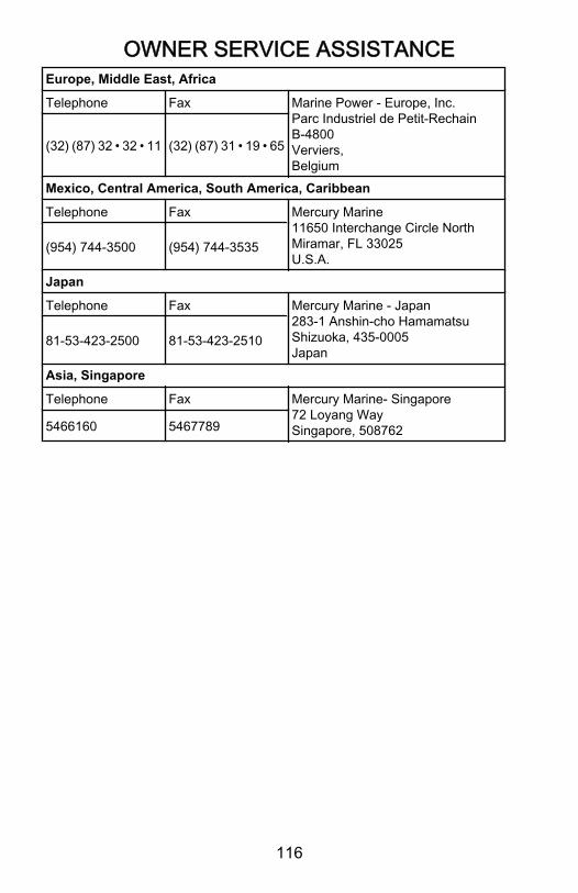
OWNER SERVICE ASSISTANCE
116
Europe, Middle East, Africa
Telephone Fax Marine Power - Europe, Inc.Parc Industriel de Petit-RechainB-4800Verviers,Belgium
(32) (87) 32 • 32 • 11 (32) (87) 31 • 19 • 65
Mexico, Central America, South America, Caribbean
Telephone Fax Mercury Marine11650 Interchange Circle NorthMiramar, FL 33025U.S.A.
(954) 744‑3500 (954) 744‑3535
Japan
Telephone Fax Mercury Marine - Japan283-1 Anshin-cho HamamatsuShizuoka, 435-0005Japan
81‑53‑423‑2500 81‑53‑423‑2510
Asia, Singapore
Telephone Fax Mercury Marine- Singapore72 Loyang WaySingapore, 5087625466160 5467789

ORDERING LITERATURE
117
United States and CanadaBefore ordering literature, please have the following informationabout your power package available:
EngineModel: Horsepower:
SerialNumber: Model year:
For information on additional literature that is available for yourparticular Mercury/MerCruiser power package and how to orderthat literature contact your nearest dealer or contact:
MERCURY MARINETelephone Fax Mail
(920) 929‑5110 (920) 929‑4894
Mercury MarineAttn: Publications Department
P.O. Box 1939Fond du Lac, WI 54936-1939
Outside The United States and CanadaBefore ordering literature, please have the following informationabout your power package available:
EngineModel: Horsepower:
SerialNumber: Model year:
Contact your nearest dealer or Marine Power Service Center forinformation on additional literature that is available for yourparticular Mercury/MerCruiser power package and how to orderthat literature.

MAINTENANCE LOG
118
Maintenance LogRecord all maintenance performed on your outboard here. Be sureto save all work orders and receipts.
Date Maintenance Performed Engine Hours