Embed Size (px)
Citation preview

MEMS-tunable dielectric metasurface lens
Ehsan Arbabi,1 Amir Arbabi,1, 2 Seyedeh Mahsa Kamali,1 Yu
Horie,1 MohammadSadegh Faraji-Dana,1 and Andrei Faraon1, ∗
1T. J. Watson Laboratory of Applied Physics, California Institute of Technology,
1200 E. California Blvd., Pasadena, CA 91125, USA2Department of Electrical and Computer Engineering,
University of Massachusetts Amherst,
151 Holdsworth Way, Amherst, MA 01003, USA
∗ Corresponding author: A.F.: [email protected]
1
arX
iv:1
712.
0654
8v2
[ph
ysic
s.op
tics]
8 M
ar 2
018

Varifocal lenses, conventionally implemented by changing the axial distance between mul-
tiple optical elements, have a wide range of applications in imaging and optical beam scan-
ning. The use of conventional bulky refractive elements makes these varifocal lenses large,
slow, and limits their tunability. Metasurfaces, a new category of lithographically defined
diffractive devices, enable thin and lightweight optical elements with precisely engineered
phase profiles. Here, we demonstrate tunable metasurface doublets, based on microelec-
tromechanical systems (MEMS), with more than 60 diopters (about 4%) change in the op-
tical power upon a 1-µm movement of one metasurface, and a scanning frequency that can
potentially reach a few kHz. They can also be integrated with a third metasurface to make
compact microscopes (∼1 mm thick) with a large corrected field of view (∼500 µm or 40 de-
grees) and fast axial scanning for 3D imaging. This paves the way towards MEMS-integrated
metasurfaces as a platform for tunable and reconfigurable optics.
INTRODUCTION
Lenses are ubiquitous optical elements present in almost all imaging systems. Compact lenses
with tunable focal/imaging distance have many applications, and therefore several methods have
been developed to make such devices [1–18]. Deformable solid and liquid-filled lenses with me-
chanical [1] , electro-mechanical [2, 12], electrowetting [9, 10], and thermal [11] tuning mech-
anisms have been demonstrated. Although these devices are more compact than regular multi-
element varifocal lenses, they are still bulky (since they are regular refractive devices), and have
low tuning speeds (ranging from a few Hz to a few tens of Hz). Liquid crystal lenses with tun-
able focus [3–5] have higher tuning speeds, but they suffer from polarization dependence and
limited tuning range. Freeform optical elements (e.g. Alvarez lenses) that can tune the focal
distance upon lateral displacement of the elements have also been demonstrated [13, 14]. These
devices are generally based on mechanical movement of bulky elements and are therefore not very
compact nor fast. Highly tunable diffractive and metasurface lenses based on stretchable sub-
strates [15, 16, 19] have also been demonstrated, but they have low speeds and require a radial
stretching mechanism that might increase the total device size. Spatial light modulators (SLMs)
and other types of diffractive elements that have pixels with controllable phase shifts have been
used and proposed [17, 18] to achieve tunable beam steering and focusing. Liquid crystal based
SLMs are polarization dependent and have limited speed and numerical apertures, and other pro-
2

posals yet await an experimental demonstration of phase tuning over two dimensional arrays with
high efficiency [17, 20].
Optical metasurfaces [21, 22] are planar arrangements of scatterers designed to manipulate var-
ious properties of an incident light beam. In the optical regime, dielectric metasurfaces are very
versatile as they allow for wavefront control with high efficiency and subwavelength resolution.
Several devices with the ability to control the phase [23–37], polarization [38, 39], polarization
and phase [40], or spectral components of light through harmonic generation [41–43] or filter-
ing [44–47] have been demonstrated. Their thin form factor makes them suitable for development
of ultrathin conformal optical elements [48, 49], and their compatibility with conventional micor-
fabrication techniques allows for monolithic fabrication of optical systems consisting of multiple
metasurfaces on a single chip [50, 51]. These characteristics (i.e., the ability to precisely control
the phase with subwavelength resolution and high gradients, thin and light form factor, and com-
patibility with microfabrication techniques) also make them very attractive for integration with the
microelectromechanical systems (MEMS) technology to develop metasurface-based micro-opto-
electromechanical systems (MOEMS). To date, integration of metasurfaces and MEMS devices
has been limited to moving uniform high-contrast grating mirrors to tune the resonance wave-
length of Fabry-Perot cavities [52, 53], or change roundtrip propagation length of light to form
spatial light modulators [54].
In this manuscript, we propose and demonstrate a metasurface doublet composed of a converg-
ing and a diverging metasurface lens with an electrically tunable focal distance. The large and
opposite-sign optical powers of the two elements, as well as their very close proximity, make it
possible to achieve large tuning of the optical power (∼60 diopters, corresponding to about 4%)
with small movements of one element (∼1 micron). We have developed a fabrication process for
making such metasurface doublets, and experimentally show metasurface lenses with over 60 µm
tuning of the effective focal length (EFL) from 565 µm to 629 µm, corresponding to a ∼180-
diopter change in the optical power. Arrays of these devices can be fabricated on the same chip to
allow for multiple lenses with different focal distances scanning different depths with frequencies
potentially reaching several kHz. In addition, we show that such devices can be combined with
the recently demonstrated monolithic metasurface optical systems design [50] to develop compact
focus-scanning objectives with corrected monochromatic aberrations over a large field of view. It
is worth noting that MOEMS devices with the ability to axially scan the focus have previously
been demonstrated based on integration of refractive and Fresnel microlenses with axially moving
3

frames [6–8, 55]. However, in these devices the focal point is scanned by the same distance that
the lens is moved, and the effective focal length (or equivalently the optical power) is not actually
tuned. Nevertheless, the concepts and techniques used in such devices can be combined with the
metasurface doublet demonstrated here to achieve enhanced functionalities (e.g. enable lateral
scanning of focus).
RESULTS
Concept and design. Figure 1a shows a schematic of the tunable focus doublet. The system
consists of a stationary metasurface on a glass substrate, and a moving metasurface on a SiNx
membrane. The membrane can be electrostatically actuated to change the distance between the
two metasurfaces. The lenses are designed such that a small change in the distance between them,
∆x ∼1 µm, leads to a large tuning of the focal length (∆ f ∼36 µm change in the front focal
length from 781 µm to 817 µm when the lens separation is changed from 10 µm to 9 µm, see
Supplementary Fig. 1 for the phase profiles and their ray tracing simulations). The membrane
and glass lenses are 300 µm in diameter, and have focal lengths of ∼120 µm and ∼-130 µm,
respectively. The electrostatic actuation is achieved through contacts only to the glass substrate.
The capacitor plates are shown in the inset of Fig. 1a. The contacts are configured to make two
series capacitors. Each capacitor has one plate on the glass substrate and another one on the
membrane, resulting in an attractive force between the membrane and the glass substrate. Figures
1b and 1c show the first two mechanical resonance modes of the membrane at ∼2.6 kHz and
∼5.6 kHz, respectively. This limits the operation frequency of the device to ∼4 kHz to avoid
unwanted excitation of the second resonance.
The metasurfaces are based on high contrast dielectric transmitarrays [23, 27]. These devices
consist of arrays of high index dielectric scatterers (nano-posts) with different shapes and sizes.
With proper design, the nano-posts enable complete control of phase and polarization on a sub-
wavelength scale [38, 40, 56]. When only phase control is required, the nano-posts should have
a symmetric cross-section (i.e., square, circular, etc.). For fabrication considerations, we choose
nano-posts with square-shaped cross-section on a square lattice. Since both the moving and sta-
tionary metasurface lenses have high numerical apertures (NA∼0.8), we used a recently developed
technique for choosing the metasurface parameters (i.e., amorphous silicon layer thickness, lat-
tice constant, and minimum and maximum post side lengths) to maximize the efficiency of high
4

NA lenses for both transverse electric (TE) and transverse magnetic (TM) polarizations [57]. The
method is based on approximating the efficiency of a lens designed with certain metasurface pa-
rameters through efficiencies of periodic gratings designed with the same parameters. Using this
method and considering the design wavelength of 915 nm, the α-Si layer thicknesses were chosen
to be 530 nm and 615 nm for the moving and stationary lenses, respectively. The lattice constant
was set to 320 nm in both cases. Figures 1d and 1e show simulated transmission amplitudes and
phases for uniform arrays of nano-posts on the membrane and the glass substrate, respectively.
Given a required phase profile, one can find the best nano-post for each site on the metasurface
using Figs. 1d or 1e [27].
Device fabrication. A summary of the key fabrication steps for the moving and stationary lenses
is schematically depicted in Figs. 2a-2f (for more details see the Methods section). The moving
metasurface fabrication was started on a silicon wafer with a ∼210-nm-thick low stress SiNx . A
20-nm-thick SiO2 layer followed by a 530-nm-thick α-Si layer was deposited on the SiNx layer.
The SiO2 layer acts both as an adhesion promoter between the SiNx and the α-Si layers, and as
an etch-stop during the dry-etch process to form the metasurface. In the next step, patterns for
backside holes were defined and transferred to an alumina layer. This layer was then used as a
hard mask to partially etch through the silicon wafer (a ∼50-µm-thick layer was left to maintain
the mechanical strength of the sample during the next steps). Alignment marks were then etched
through the α-Si layer for aligning the top and bottom sides. The metasurface lens was then
patterned into the α-Si layer. Next, the metallic contacts were deposited and patterned. The top
side of the device was covered with a protective polymer, and the remaining part of the wafer under
the membrane was wet etched. Finally, the membrane was patterned and dry etched to release the
metasurface. An optical image of the fabricated metasurface on a membrane is shown in Fig. 2b.
Due to the residual stress in the membranes, the beams are slightly bent such that the central part
of the lens is about 6 to 8 µm above the surface of the wafer.
The fabrication steps of the stationary metasurface are schematically shown in Fig. 2c. A 615-
nm-thick layer of α-Si was deposited on a glass substrate. The metasurface pattern was generated
and etched through the layer, followed by deposition and patterning of the contacts. An optical
image of a completed metasurface on the glass substrate is shown in Fig. 2d. Finally, a 20 µm
spacer layer was spin coated and patterned on the glass substrate (to achieve a ∼12 µm distance
between the lenses), and the two chips were aligned and bonded with an ultra-violet (UV) curable
epoxy (Fig. 2e). An optical image of the final device is shown in Fig. 2f. Figures 2g and 2h show
5
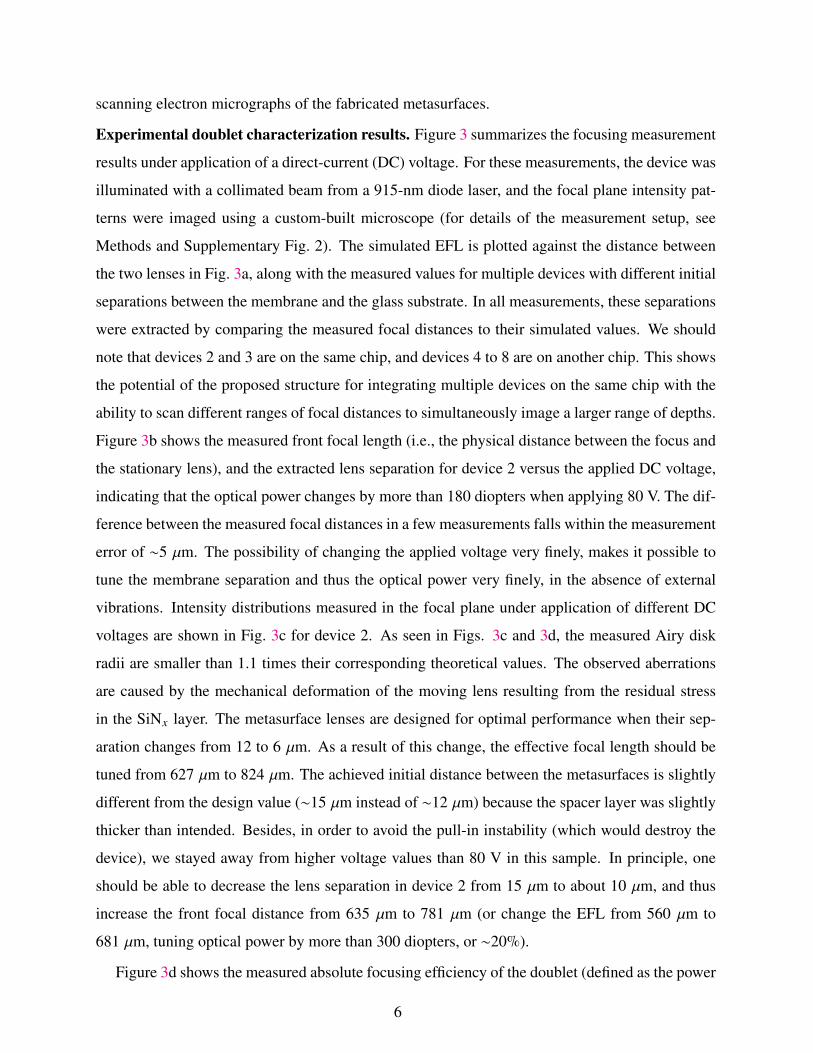
scanning electron micrographs of the fabricated metasurfaces.
Experimental doublet characterization results. Figure 3 summarizes the focusing measurement
results under application of a direct-current (DC) voltage. For these measurements, the device was
illuminated with a collimated beam from a 915-nm diode laser, and the focal plane intensity pat-
terns were imaged using a custom-built microscope (for details of the measurement setup, see
Methods and Supplementary Fig. 2). The simulated EFL is plotted against the distance between
the two lenses in Fig. 3a, along with the measured values for multiple devices with different initial
separations between the membrane and the glass substrate. In all measurements, these separations
were extracted by comparing the measured focal distances to their simulated values. We should
note that devices 2 and 3 are on the same chip, and devices 4 to 8 are on another chip. This shows
the potential of the proposed structure for integrating multiple devices on the same chip with the
ability to scan different ranges of focal distances to simultaneously image a larger range of depths.
Figure 3b shows the measured front focal length (i.e., the physical distance between the focus and
the stationary lens), and the extracted lens separation for device 2 versus the applied DC voltage,
indicating that the optical power changes by more than 180 diopters when applying 80 V. The dif-
ference between the measured focal distances in a few measurements falls within the measurement
error of ∼5 µm. The possibility of changing the applied voltage very finely, makes it possible to
tune the membrane separation and thus the optical power very finely, in the absence of external
vibrations. Intensity distributions measured in the focal plane under application of different DC
voltages are shown in Fig. 3c for device 2. As seen in Figs. 3c and 3d, the measured Airy disk
radii are smaller than 1.1 times their corresponding theoretical values. The observed aberrations
are caused by the mechanical deformation of the moving lens resulting from the residual stress
in the SiNx layer. The metasurface lenses are designed for optimal performance when their sep-
aration changes from 12 to 6 µm. As a result of this change, the effective focal length should be
tuned from 627 µm to 824 µm. The achieved initial distance between the metasurfaces is slightly
different from the design value (∼15 µm instead of ∼12 µm) because the spacer layer was slightly
thicker than intended. Besides, in order to avoid the pull-in instability (which would destroy the
device), we stayed away from higher voltage values than 80 V in this sample. In principle, one
should be able to decrease the lens separation in device 2 from 15 µm to about 10 µm, and thus
increase the front focal distance from 635 µm to 781 µm (or change the EFL from 560 µm to
681 µm, tuning optical power by more than 300 diopters, or ∼20%).
Figure 3d shows the measured absolute focusing efficiency of the doublet (defined as the power
6

passing through a ∼20-µm-diameter aperture to the total power hitting the device). The absolute
efficiency is between 40% and 45% for all applied voltage values. The high-NA (NA∼0.8) singlets
used here are expected to be ∼75% efficient [57]. Because the doublet uses two of such lenses,
its efficiency is estimated to be ∼55%. Taking into account the reflections at the three air-glass
interfaces (a glass wafer is used to cap the backside of the membrane to fully isolate it from the
environment airflow), we obtain a total efficiency of ∼50% which agrees well with the measured
efficiency values. We attribute the slightly lower measured efficiency to fabrication imperfections.
It is foreseeable that the efficiency can be significantly improved with better optimization and
design processes [35], use of anti-reflection coatings to reduce reflection losses, and optimizing
the fabrication process.
The frequency response of the doublet is measured and plotted in Fig. 3e (see Supplementary
Note 1 and Supplementary Fig. 2 for details of frequency response measurement). The frequency
response transfer function is defined as the membrane displacement at frequency f , normalized
to its value under the same voltage applied in DC. The black dashed line shows the -3-dB line,
showing a ∼230 Hz bandwidth for the device. The red and blue dashed lines show second order
system fits (i.e., H( f ) = 11−i(b/
√mk)( f / f0)−( f / f0)2
, where f0 is the resonance frequency for the first
mode, b is a damping factor, and m and k are the oscillator mass and spring constant, respectively),
indicating that the fit follows the measurement well for b = 20√
mk. This corresponds to a highly
overdamped system with a damping ratio (b/2√
mk) of ∼10. Under the atmosphere pressure the
dominant loss mechanism is the air damping [58]. If the damping is reduced by about 20 times
by reducing the air pressure inside the lens packaging (i.e., b/2√
mk ≈ 0.5), then the frequency
response will follow the blue dashed line in Fig. 3e, with a 3-dB bandwidth reaching 4 kHz. This
would correspond to a quality factor of ∼1 for the mechanical resonator, which should be feasible
by reducing air damping. In addition, at such a low quality factor, oscillation and long settling
times should not be an issue. Vacuum packaging could be done through bonding the backside
glass substrate (the one with no metasurface) and the silicon chip carrying the membrane in a
vacuum chamber with controllable pressure.
Imaging with electrical focusing. The tunable doublet can be used for imaging with electrically
controlled focusing. To demonstrate this, we formed an imaging setup using the doublet and a
refractive lens. The setup is schematically shown in Fig. 4a. A transmissive object was placed in
front of the imaging system. A 1.8-mm diameter pinhole was placed in front of the aspheric lens
to reduce the aperture and increase contrast. The system images the object to a plane ∼130 µm
7

outside the stationary lens substrate. Since this image is very small and close to the lens, we used
a custom-built microscope (×55 magnification) to re-image it onto the camera. The results are
summarized in Fig. 4b. When the object is p ∼15 mm away and no voltage is applied, the image is
out of focus. If the applied voltage is increased to 85 V in the same configuration, the image comes
to focus. Changing the object distance to p ∼9.2 mm, the voltage should also be changed to 60 V
to keep the image in focus. At 0 V, the object should be moved to p ∼4 mm to be in focus, and
applying 85 V to the doublet will result in a completely out of focus image in this configuration.
As observed here, by moving the membrane only about 4 µm, the overall system EFL changes
from 44 mm to 122 mm, a ratio of about 1:2.8. This is an example of the importance of the large
absolute optical power tunability of the metasurface doublet, especially when it is integrated into
a system with a comparably small overall optical power. It also allows for changing the object
distance from 4 mm to 15 mm by electrically controlled refocusing.
Electrically tunable compact microscope. To further demonstrate the capabilities of this plat-
form, we use it to design a 1-mm-thick electrically tunable microscope. The structure is schemati-
cally shown in Fig. 5a, and is a metasurface triplet composed of a tunable doublet (with an optical
design different from the fabricated one), and an additional metasurface lens. The lenses, from left
to right are 540 µm, 560 µm, and 400 µm in diameter. They have focal lengths of about -290 µm,
275 µm, and 1470 µm. The glass substrate is 1-mm thick, and the image plane is located 14 mm
behind the third lens. The stop aperture is located at the plane of the right-most lens, and has the
same diameter of 400 µm. By moving the membrane and changing the separation d from 13 µm to
5 µm, the object plane distance D changes from 622 µm to 784 µm. The triplet can be optimized
to correct for monochromatic aberrations [50] to keep the focus close to the diffraction limit over a
large field of view (see Supplementary Fig. 1 for phase profiles, and Supplementary Table 2 for the
corresponding coefficients). Here, we have optimized the phase profiles to keep the focus almost
diffraction limited in a ∼500 µm diameter field of view (corresponding to a ∼40-degree field of
view in the D=700 µm case). Spot diagrams of point sources at 0, 125, and 250 µm distances from
the optical axis are shown in Fig. 5b, demonstrating a diffraction limited behavior. The spot dia-
grams are ray-optics simulation results from a point source at their corresponding distances from
the optical axis. The red circles show the diffraction limited Airy disks for different cases, with
∼40-µm radii. Figure 5c shows the image formation simulation results for the system at three dif-
ferent values of d (and D). The insets show that the system can resolve the ∼3.5 µm line-space in
an object. The effective focal length for the whole system is ∼1160 µm (for d=9 µm case), which
8

is significantly larger than the focal lengths of the membrane and first glass lenses, similar to the
fabricated doublet. As a result, the object space NA is about 0.16, corresponding to a resolution
of ∼3.5 µm at the object plane. Considering the 14-mm distance between the image plane and the
backside aperture, the image space NA is ∼0.014 which results in an Airy radius of about 40 µm
in the image plane. As the effective focal length of the system changes with tuning d, the total
magnification of the system also changes from 11.3 (for d=5 µm) to 10.3 (for d=13 µm).
DISCUSSION
The lenses demonstrated here have small sub-millimeter aperture sizes suitable for applications
in ultra-compact optical systems. In principle, the lenses can have centimeter-scale apertures as
silicon nitride membranes at these scales have already been demonstrated [59, 60]. In addition,
the electrostatic forces and the mechanical resonance frequencies can be engineered by appropriate
choice of the electrostatic actuation plate areas, membrane thickness, and mechanical beam design.
The high optical power of the elements, and the small aperture of the doublet result in a rel-
atively high sensitivity to the membrane bending, and to misalignment between the two lenses
(see Supplementary Fig. 3 for modulation transfer function and Strehl ratio simulation results).
We estimate the radius of curvature of the measured membranes to be ∼20 mm, using mechanical
simulations of the structure and the observed ∼6-µm distance between the center of the lens and
the surface of the wafer. This would result in a Strehl ratio slightly larger than 0.95. A Strehl
ratio of 0.9 (as an acceptability criterion) corresponds to a radius of curvature of ∼15 mm. If the
membrane curvature is larger than this and known a priori, the lens design can be optimized to
include the effects of the bending. In addition, to have a Strehl ratio better than 0.9, the misalign-
ment between the two lenses should be better than 2 µm. Based on the symmetric measured focal
spots, we estimate the misalignment in the doublets to be smaller than this limit. Considering the
high alignment precision achievable with industrial aligners, achieving a 2-µm resolution is not a
challenge.
Similar to other diffractive and metasurface optical devices, the lenses demonstrated here suf-
fer from chromatic aberrations [61–63]. The exact “acceptable” operation bandwidth of the lens
depends on the effective focal length, the numerical aperture, and a criterion for “acceptability”.
Using the criterion given in [50] that is based on the focal spot area increasing to twice its value
at the center wavelength, and assuming an effective focal length of ∼600 µm (corresponding to a
9

numerical aperture of 0.24), the operation bandwidth is given by ∆λ = 2.27λ2/( f NA2) ≈ 50 nm.
To make multiwavelength tunable doublets, many of the recently demonstrated approaches for
making multiwavelength metasurfaces can be directly applied [56, 64–66]. In addition, the re-
cently introduced concept of phase-dispersion control [67–69] can be used to increase the opera-
tion bandwidth of the metasurface lenses by correcting the chromatic aberrations over a continuous
bandwidth.
Here we introduced a category of MOEMS devices based on combining metasurface optics
with the MEMS technology. To showcase the capabilities of the proposed platform, we exper-
imentally demonstrated tunable lenses with over 180 diopters change in the optical power, and
measured focusing efficiencies exceeding 40%. In principle, the optical power tunability could
be increased to above 300 diopters for the presented design. We demonstrated how such tunable
lenses can be used in optical systems to provide high-speed electrical focusing and scanning of
the imaging distance. The potentials of the introduced technology go well beyond what we have
demonstrated here, and the devices can be designed to enable compact fast-scanning endoscopes,
fiber-tip-mounted confocal microscopes, etc. In principle, metasurfaces can replace many of the
refractive and diffractive micro-optical elements used in conventional MOEMS devices to make
them more compact, increase their operation speed, and enhance their capabilities.
10

METHODS
Simulation. The optimized phase profiles (for both the fabricated doublet and the triplet shown
in Fig. 5) were obtained using Zemax OpticStudio. The phase profiles are defined as even-order
polynomials of the radial coordinate r according to φ(r) = ∑2n a2n(r/R0)2n, where R0 is a normal-
ization radius and a2n are the coefficients (see Supplementary Fig. 1 and Supplementary Table 1
for the phase profiles and the optimized coefficients). This was done through simultaneously min-
imizing the root mean square radius of the focal spot for several configurations (i.e., different lens
separations, and, in the case of the triplet, the lateral source position). The image formation sim-
ulations (for Fig. 5) were done using the extended scene simulations of Zemax OpticStudio and
took into account the aberrations and limitations resulting from diffraction.
Mechanical simulation of the MEMS structure was performed in COMSOL Multiphysics to
find the resonances of the structure. The metallic contacts and the α-Si metasurface were treated
as additional masses on the membrane. The Young modulus of SiNx was assumed to be 250 GPa
and its Poisson ratio was set to be 0.23. The following densities were used for different materials:
3100 kgm−3 for SiNx , 2320 kg/m−3 for α-Si, and 19300 kg/m−3 for gold. To account for the fact
that the whole metasurface volume is not filled with α-Si, an average fill factor of 0.5 was used.
Transmission amplitudes and phases of the metasurface structures on both fused silica and
silicon nitride were computed through rigorous coupled-wave analysis [70]. The transmission
values were calculated by illuminating a uniform array of nano-posts with a normally incident
plane wave at 915 nm wavelength and finding the amplitude and phase of the transmitted zeroth-
order wave right above the nano-posts. The subwavelength lattice ensures that this single number
is adequate to describe the optical behavior of a uniform array. The following refractive indices
were used in the simulations: 3.5596 for α-Si, 2.1 for SiNx , 1.4515 for fused silica. The lattice
constant was 320 nm in both cases, and the α-Si thickness was 530 nm for the moving, and 615 nm
for the stationary lens.
Device fabrication. Fabrication of the stationary lenses was started by depositing a 615-nm-thick
layer of α-Si on a 500-µm-thick fused silica substrate through a plasma enhanced chemical vapor
deposition (PECVD) process. The metasurface pattern was written on a ∼300-nm-thick layer of
ZEP520A positive electron resist with a Vistec EBPG5000+ electron beam lithography system.
After development of the resist, a 70-nm-thick alumina layer was evaporated on the sample that
was used as a hard mask. The pattern was then transformed to the α-Si layer via a dry etch process.
11

The metallic contacts’ pattern was defined using photolithography on AZ 5214 E photoresist which
was used as a negative resist. A ∼10-nm-thick layer of Cr, followed by a ∼100-nm-thick Au layer
was evaporated onto the sample, and a lift-off process transferred the photoresist pattern to the
metal layer. Finally, a ∼20-µm-thick layer of SU-8 2015 was spin coated on the sample and
patterned to function as a spacer.
The moving lens fabrication started with a silicon wafer with ∼450-nm-thick low-stress low-
pressure chemical vapor SiNx deposited on both sides. The device side was etched down to about
213 nm with a dry etch process. A ∼20-nm-thick SiO2 layer, followed by a ∼530-nm-thick α-Si
layer was deposited on the sample with a PECVD process. Through hole patterns were defined on
the backside of the sample using the AZ 5214 E photoresist, and a lift-off process was performed
to transfer the pattern to a ∼200-nm-thick alumina layer that was used as a hard mask. The holes
were partially etched through the wafer with a Bosch process (leaving a ∼50-µm-thick silicon
layer to provide mechanical support for the membrane in the following steps). Alignment marks
(for aligning the lenses to the backside holes) were patterned and etched into the α-Si layer using
a backside-aligned photolithography process. A process similar to the one used for the stationary
lenses was performed to fabricate the metasurfaces and the metallic contacts. The top-side (with
the metasurfaces and contacts) was then covered with a protective polymer coating (ProTEK PSB,
Brewer Science) layer, and the remaining ∼50-µm-thick silicon layer was etched in a 3:1 water-
diluted potassium hydroxide solution at 80◦C. The membrane pattern was defined on the sample
using photolithography with AZ nLOf 2020 photoresist, and was etched through the SiNx mem-
brane to release the membrane. The photoresist was then removed in an oxygen plasma. A fused
silica piece was bonded to the backside of the membrane sample using a UV-curable epoxy (NOA
89, Norland Products) to isolate the membranes from ambient airflow. At the end, the moving and
stationary samples were aligned and bonded using an MA6/BA6 aligner (Suss MicroTec). A UV-
curable epoxy was used to bond the two samples. Using this technique, an alignment precision of
a few microns is feasible.
Measurement procedure. The doublet characterization setup is schematically shown in Supple-
mentary Fig. 2. A collimated beam from a fiber coupled 915-nm diode laser connected to a fiber
collimation package (F240FC-B, Thorlabs) was used to illuminate the doublet from the membrane
side. A custom-built microscope consisting of a ×50 objective (Olympus LCPlanFL N, NA=0.7)
and a tube lens with a 20-cm focal length was used to image the focal plane of the doublet to
a charge-coupled device camera (CoolSNAP K4, Photometrics). An air coplanar probe (ACP40
12

GSG 500, Cascade Microtech) was used to apply a voltage to the doublet. For measuring the fre-
quency response, square pulses with different base frequencies were applied to the probe (CFG250
function generator, Tektronix). The change in the optical power passing through a 50-µm pinhole
in the image plane (equivalent to a ∼1-µm pinhole in the focal plane) was then measured with a
fast detector (PDA36A, Thorlabs) connected to an oscilloscope. The frequency response was then
extracted through Fourier transforming the input voltage and the resulting change in the output
power (see Supplementary Note 1 for more details).
The efficiency was calculated through measuring the power passing through a ∼1-mm iris in
the image plane (corresponding to a ∼20-µm pinhole in the focal plane) and dividing it by the total
power before the doublet. To make sure that the total beam power was incident on the doublet,
the beam was partially focused by a lens with a 10-cm focal length. The distance between the
lens and the doublet was adjusted such that the beam had a ∼100-µm full-width at half-maximum
(FWHM) at the place of the doublet (i.e., one third of the doublet diameter). This way, more than
99% of the power is expected to hit the doublet area.
The imaging experiments in Fig. 4 were also performed using a similar setup. For imaging, a
910-nm LED (LED910E, Thorlabs) was used as an illumination. To reduce the effects of chro-
matic dispersion, a bandpass filter (FB910-10, 910-nm center wavelength, 10-nm FWHM) was
placed in front of the camera. A negative 1951 USAF Resolution target (R1DS1N, Thorlabs)
was used as an imaging object. A 4- f system consisting the doublet and a glass lens with focal
length of 8 mm (ACL12708U-B, Thorlabs) was used to form images of the resolution target at
different distances. To reduce the aperture size and increase contrast, a 1.8-mm-diameter aperture
(AP1.5, Thorlabs) was placed at a ∼1.3-mm distance in front of the refractive lens. The distance
between the backside of the refractive lens and the doublet was ∼4.5 mm. The resulting image
was magnified and re-imaged onto the camera with the same microscope used for the focal spot
characterization.
13

REFERENCES
[1] Jeong, K.-H., Liu, G. L., Chronis, N. & Lee, L. P. Tunable microdoublet lens array. Opt. Express 12,
2494–2500 (2004).
[2] Lee, S. W. & Lee, S. S. Focal tunable liquid lens integrated with an electromagnetic actuator. Appl.
Phys. Lett. 90, 121129 (2007).
[3] Sato, S. Liquid-crystal lens-cells with variable focal length. Jpn. J. Appl. Phys. 18, 1679–1684 (1979).
[4] Ren, H., Fan, Y.-H., Gauza, S. & Wu, S.-T. Tunable-focus flat liquid crystal spherical lens. Appl.
Phys. Lett. 84, 4789–4791 (2004).
[5] Pishnyak, O., Sato, S. & Lavrentovich, O. D. Electrically tunable lens based on a dual-frequency
nematic liquid crystal. Appl. Opt. 45, 4576–4582 (2006).
[6] Kwon, S. & Lee, L. P. Stacked two dimensional micro-lens scanner for micro confocal imaging
array. In Technical Digest. MEMS 2002 IEEE International Conference. Fifteenth IEEE International
Conference on Micro Electro Mechanical Systems (Cat. No.02CH37266), 483–486 (2002).
[7] Kwon, S., Milanovic, V. & Lee, L. P. Large-displacement vertical microlens scanner with low driving
voltage. IEEE Photon. Technol. Lett. 14, 1572–1574 (2002).
[8] Baranski, M. et al. Micro-optical design of a three-dimensional microlens scanner for vertically inte-
grated micro-opto-electro-mechanical systems. Appl. Opt. 54, 6924–6934 (2015).
[9] Krogmann, F., Mönch, W. & Zappe, H. A MEMS-based variable micro-lens system. J. Opt. A Pure
Appl. Opt. 8, S330–S336 (2006).
[10] Li, L., Wang, D., Liu, C. & Wang, Q.-H. Zoom microscope objective using electrowetting lenses.
Opt. Express 24, 2931–2940 (2016).
[11] Lee, S.-Y., Tung, H.-W., Chen, W.-C. & Fang, W. Thermal actuated solid tunable lens. IEEE Photon.
Technol. Lett. 18, 2191–2193 (2006).
[12] Shian, S., Diebold, R. M. & Clarke, D. R. Tunable lenses using transparent dielectric elastomer
actuators. Opt. Express 21, 8669–8676 (2013).
[13] Zou, Y., Zhang, W., Chau, F. S. & Zhou, G. Miniature adjustable-focus endoscope with a solid
electrically tunable lens. Opt. Express 23, 20582–20592 (2015).
[14] Zhan, A., Colburn, S., Dodson, C. M. & Majumdar, A. Metasurface freeform nanophotonics. Sci.
14

Rep. 7, 1673 (2017).
[15] Kamali, S. M., Arbabi, E., Arbabi, A., Horie, Y. & Faraon, A. Highly tunable elastic dielectric
metasurface lenses. Laser Photon. Rev. 10, 1062–1062 (2016).
[16] Ee, H.-S. & Agarwal, R. Tunable metasurface and flat optical zoom lens on a stretchable substrate.
Nano Lett. 16, 2818–2823 (2016).
[17] Sherrott, M. C. et al. Experimental demonstration of >230◦ phase modulation in gate-tunable
graphene-gold reconfigurable mid-infrared metasurfaces. Nano Lett. 17, 3027–3034 (2017).
[18] Colburn, S., Zhan, A. & Majumdar, A. Tunable metasurfaces via subwavelength phase shifters with
uniform amplitude. Sci. Rep. 7, 40174 (2017).
[19] She, A., Zhang, S., Shian, S., Clarke, D. R. & Capasso, F. Large area electrically tunable lenses based
on metasurfaces and dielectric elastomer actuators. https://arxiv.org/abs/1708.01972 (2017).
[20] Horie, Y., Arbabi, A., Arbabi, E., Kamali, S. M. & Faraon, A. High-speed, phase-dominant spatial
light modulation with silicon-based active resonant antennas. ACS Photonics (2017).
[21] Staude, I. & Schilling, J. Metamaterial-inspired silicon nanophotonics. Nat. Photon. 11, 274–284
(2017).
[22] Hsiao, H.-H., Chu, C. H. & Tsai, D. P. Fundamentals and applications of metasurfaces. Small Methods
1, 1600064 (2017).
[23] Lalanne, P., Astilean, S., Chavel, P., Cambril, E. & Launois, H. Blazed binary subwavelength gratings
with efficiencies larger than those of conventional échelette gratings. Opt. Lett. 23, 1081–1083 (1998).
[24] Fattal, D., Li, J., Peng, Z., Fiorentino, M. & Beausoleil, R. G. Flat dielectric grating reflectors with
focusing abilities. Nat. Photon. 4, 466–470 (2010).
[25] Lu, F., Sedgwick, F. G., Karagodsky, V., Chase, C. & Chang-Hasnain, C. J. Planar high-numerical-
aperture low-loss focusing reflectors and lenses using subwavelength high contrast gratings. Opt.
Express 18, 12606–12614 (2010).
[26] Vo, S. et al. Sub-wavelength grating lenses with a twist. IEEE Photon. Technol. Lett. 26, 1375–1378
(2014).
[27] Arbabi, A., Horie, Y., Ball, A. J., Bagheri, M. & Faraon, A. Subwavelength-thick lenses with high
numerical apertures and large efficiency based on high-contrast transmitarrays. Nat. Commun. 6, 7069
(2015).
[28] Lin, D., Fan, P., Hasman, E. & Brongersma, M. L. Dielectric gradient metasurface optical elements.
Science 345, 298–302 (2014).
15

[29] Ren, Y. et al. Orbital angular momentum-based space division multiplexing for high-capacity under-
water optical communications. Sci. Rep. 6, 33306 (2016).
[30] Zhan, A. et al. Low-contrast dielectric metasurface optics. ACS Photonics 3, 209–214 (2016).
[31] Khorasaninejad, M. et al. Metalenses at visible wavelengths: Diffraction-limited focusing and sub-
wavelength resolution imaging. Science 352, 1190–1194 (2016).
[32] Wang, L. et al. Grayscale transparent metasurface holograms. Optica 3, 1504–1505 (2016).
[33] Paniagua-Dominguez, R. et al. A metalens with near-unity numerical aperture.
https://arxiv.org/abs/1705.00895 (2017).
[34] Jang, M. et al. Complex wavefront engineering with disorder-engineered metasurfaces.
https://arxiv.org/abs/1706.08640 (2017).
[35] Sell, D., Yang, J., Doshay, S., Yang, R. & Fan, J. A. Large-angle, multifunctional metagratings based
on freeform multimode geometries. Nano Lett. 17, 3752–3757 (2017).
[36] Zhou, Z. et al. Efficient silicon metasurfaces for visible light. ACS Photonics 4, 544–551 (2017).
[37] Kamali, S. M. et al. Angle-multiplexed metasurfaces: Encoding independent wavefronts in a single
metasurface under different illumination angles. Phys. Rev. X 7, 041056 (2017).
[38] Backlund, M. P. et al. Removing orientation-induced localization biases in single-molecule mi-
croscopy using a broadband metasurface mask. Nat. Photon. 10, 459–462 (2016).
[39] Kruk, S. et al. Invited article: Broadband highly efficient dielectric metadevices for polarization
control. APL Photonics 1, 030801 (2016).
[40] Arbabi, A., Horie, Y., Bagheri, M. & Faraon, A. Dielectric metasurfaces for complete control of phase
and polarization with subwavelength spatial resolution and high transmission. Nat. Nanotechnol. 10,
937–943 (2015).
[41] Liu, S. et al. Resonantly enhanced second-harmonic generation using III-V semiconductor all-
dielectric metasurfaces. Nano Lett. 16, 5426–5432 (2016).
[42] Camacho-Morales, R. et al. Nonlinear generation of vector beams from AlGaAs nanoantennas. Nano
Lett. 16, 7191–7197 (2016).
[43] Makarov, S. V. et al. Efficient second-harmonic generation in nanocrystalline silicon nanoparticles.
Nano Lett. 17, 3047–3053 (2017).
[44] Horie, Y., Arbabi, A., Han, S. & Faraon, A. High resolution on-chip optical filter array based on
double subwavelength grating reflectors. Opt. Express 23, 29848–29854 (2015).
[45] Horie, Y., Arbabi, A., Arbabi, E., Kamali, S. M. & Faraon, A. Wide bandwidth and high resolution
16

planar filter array based on DBR-metasurface-DBR structures. Opt. Express 24, 11677–11682 (2016).
[46] Horie, Y. et al. Visible wavelength color filters using dielectric subwavelength gratings for backside-
illuminated CMOS image sensor technologies. Nano Lett. 17, 3159–3164 (2017).
[47] Yamada, K. et al. Flat-top narrowband filters enabled by guided-mode resonance in two-level waveg-
uides. Opt. Lett. 42, 4127–4130 (2017).
[48] Kamali, S. M., Arbabi, A., Arbabi, E., Horie, Y. & Faraon, A. Decoupling optical function and
geometrical form using conformal flexible dielectric metasurfaces. Nat. Commun. 7, 11618 (2016).
[49] Cheng, J., Jafar-Zanjani, S. & Mosallaei, H. All-dielectric ultrathin conformal metasurfaces: lensing
and cloaking applications at 532 nm wavelength. Sci. Rep. 6, 38440 (2016).
[50] Arbabi, A. et al. Miniature optical planar camera based on a wide-angle metasurface doublet corrected
for monochromatic aberrations. Nat. Commun. 7, 13682 (2016).
[51] Arbabi, A., Arbabi, E., Horie, Y., Kamali, S. M. & Faraon, A. Planar metasurface retroreflector. Nat.
Photon. 11, 415–420 (2017).
[52] Huang, M. C. Y., Zhou, Y. & Chang-Hasnain, C. J. A nanoelectromechanical tunable laser. Nat.
Photon. 2, 180–184 (2008).
[53] Wang, Y., Stellinga, D., Klemm, A. B., Reardon, C. P. & Krauss, T. F. Tunable optical filters based on
silicon nitride high contrast gratings. IEEE J. Sel. Top. Quantum Electron. 21, 108–113 (2015).
[54] Yoo, B.-W. et al. A 32 × 32 optical phased array using polysilicon sub-wavelength high-contrast-
grating mirrors. Opt. Express 22, 19029–19039 (2014).
[55] Fan, L., Wu, M. C., Choquette, K. D. & Crawford, M. H. Self-assembled microactuated XYZ stages
for optical scanning and alignment. In International Conference on Solid State Sensors and Actuators,
vol. 1, 319–322 (1997).
[56] Arbabi, E., Arbabi, A., Kamali, S. M., Horie, Y. & Faraon, A. High efficiency double-wavelength
dielectric metasurface lenses with dichroic birefringent meta-atoms. Opt. Express 24, 18468–18477
(2016).
[57] Arbabi, A. et al. Increasing efficiency of high-NA metasurface lenses. In SPIE Photon. West, vol.
10113, 101130K–1 (SPIE, 2017).
[58] Kaajakari, V. Practical MEMS (Small Gear Pub., 2009).
[59] Serra, E. et al. Microfabrication of large-area circular high-stress silicon nitride membranes for op-
tomechanical applications. AIP Adv. 6, 065004 (2016).
[60] Moura, J. P., Norte, R. A., Guo, J., Schafermeier, C. & Groblacher, S. Centimeter-scale suspended
17

photonic crystal mirrors. https://arxiv.org/abs/1707.08128v1 (2017).
[61] O’Shea, D. C., Suleski, T. J., Kathman, A. D. & Prather, D. W. Diffractive Optics: Design, Fabrica-
tion, and Test (SPIE Press, 2004).
[62] Faklis, D. & Morris, G. M. Spectral properties of multiorder diffractive lenses. Appl. Opt. 34, 2462–
2468 (1995).
[63] Arbabi, E., Arbabi, A., Kamali, S. M., Horie, Y. & Faraon, A. Multiwavelength polarization-
insensitive lenses based on dielectric metasurfaces with meta-molecules. Optica 3, 628–633 (2016).
[64] Aieta, F., Kats, M. A., Genevet, P. & Capasso, F. Multiwavelength achromatic metasurfaces by dis-
persive phase compensation. Science 347, 1342–1345 (2015).
[65] Arbabi, E., Arbabi, A., Kamali, S. M., Horie, Y. & Faraon, A. Multiwavelength metasurfaces through
spatial multiplexing. Sci. Rep. 6, 32803 (2016).
[66] Lin, D. et al. Photonic multitasking interleaved Si nanoantenna phased array. Nano Lett. 16, 7671–
7676 (2016).
[67] Arbabi, E., Arbabi, A., Kamali, S. M., Horie, Y. & Faraon, A. Dispersionless metasurfaces using
dispersive meta-atoms. In Conference on Lasers and Electro-Optics (CLEO), FM2D.4 (2016).
[68] Arbabi, E., Arbabi, A., Kamali, S. M., Horie, Y. & Faraon, A. Controlling the sign of chromatic
dispersion in diffractive optics with dielectric metasurfaces. Optica 4, 625–632 (2017).
[69] Wang, S. et al. Broadband achromatic optical metasurface devices. Nat. Commun. 8, 187 (2017).
[70] Liu, V. & Fan, S. S4 : A free electromagnetic solver for layered periodic structures. Comput. Phys.
Commun. 183, 2233–2244 (2012).
18

FIGURES
x f
a
0
10
1
100 200Post width [nm]
|t|t/2
|t|t/2
SiNx
tE-Si
E
d
Post width [nm]0
1
80 180
tE-Si
FSE
e
b c
Tran
smis
sion
[a.u
.]
Dis
plac
emen
t [a.
u.]
Tran
smis
sion
[a.u
.]
FIG. 1 | Schematic illustration of the tunable doublet and design graphs. (a) Schematic illustration ofthe proposed tunable lens, comprised of a stationary lens on a substrate, and a moving lens on a membrane.With the correct design, a small change in the distance between the two lenses (∆x ∼1 µm) results in alarge change in the focal distance (∆ f ∼35 µm). (Insets: schematics of the moving and stationary lensesshowing the electrostatic actuation contacts.) (b) The first and (c) second mechanical resonances of themembrane at frequencies of ∼2.6 kHz and ∼5.6 kHz, respectively. The scale bars are 100 µm. (d)Simulated transmission amplitude and phase for a uniform array of α-Si nano-posts on a ∼213-nm-thickSiNx membrane versus the nano-post width. The nano-posts are 530 nm tall and are placed on the verticesof a square lattice with a lattice constant of 320 nm. (e) Simulated transmission amplitude and phase for auniform array of α-Si nano-posts on a glass substrate versus the nano-post width. The nano-posts are615 nm tall and are placed on the vertices of a square lattice with a lattice constant of 320 nm. FS: Fusedsilica.
19

a c e
g h
b d f
: c-Si : Au : FS: SiNx : SiO2 : SU-8: -Si
FIG. 2 | Fabrication process summary. (a) Simplified fabrication process of a lens on a membrane: aSiO2 spacer layer and an α-Si layer are deposited on a Si substrate with a pre-deposited SiNx layer. Thebackside of the substrate is partially etched, and alignment marks are etched into the α-Si layer. The lens ispatterned and etched into the α-Si layer, and gold contacts are evaporated on the membrane. Theremaining substrate thickness is etched and the membrane is released. c-Si: crystalline silicon; FS: fusedsilica. (b) An optical microscope image of a fabricated lens on a membrane. (c) Simplified fabricationprocess of the lens on the glass substrate: an α-Si layer is deposited on a glass substrate and patterned toform the lens. Gold contacts are evaporated and patterned to from the contacts. (d) An optical micorscopeimage of the fabricated lens on the glass substrate. (e) Schematics of the bonding process: an SU-8 spacerlayer is patterned on the glass substrate, the two chips are aligned and bonded. (f) A microscope image ofthe final device. (g) Scanning electron micrograph of the lens on the membrane, and (h) nano-posts thatform the lens. Scale bars are 100 µm in b, d, f, and g, and 1 µm in h.
20

11
13
15
0 80
640
680
f [m
]
d [
m]
720
40Voltage [V]
b
f [ m]640 680 720
0
0.5
1
d
Normalized Airy radiusEfficiency
600
800
400
EFL
[m
]d [ m]
10 20 30
SimulationaDevice 1Device 2Device 3Device 4
Device 8Device 7Device 6Device 5
v=0 V, f=635 m v=60 V, f=664 m v=70 V, f=682 m v=80 V, f=717 mc
e
Frequency [Hz]1 2 5 10 100 1000 10000
-10
0
-20Tr
ansf
er fu
nctio
n [d
B]
Effici
ency
\r- A
Measured b=20 mkb= mk
1
0
Intensity [a.u.]
FIG. 3 | Focusing measurement results of the tunable doublet. (a) Simulated EFL versus the distancebetween lenses, along with measured EFL values for 8 devices under different applied voltages. Differentdevices have different initial lens separations, resulting in different focal distances under no appliedvoltage. (b) Measured front focal length versus the applied DC voltage for device 2 of panel a. Theseparation values between the moving and stationary lenses are also plotted. (c) Intensity distributions inthe focal plane of the doublet lens at different actuation voltages. The scale bars are 2 µm. (d) MeasuredAiry radii (normalized to their corresponding diffraction limited values), r̄A, and measured absolutefocusing efficiency of the tunable doublet. (e) Measured frequency response of the system, along withsecond order transfer functions with two values of the damping factor (b) equal to 20
√mk and
√mk.
21

Objective lens
DoubletLens Tube lens
Filter
Camera
a
b
v
p=4mm, v=85Vp=4mm, v=0Vp=9.2mm, v=60V p=15mm, v=85Vp=15mm, v=0V
p
1.3 mm
FIG. 4 | Imaging with the tunable doublet. (a) Schematic illustration of the imaging setup using a regularglass lens and the tunable doublet. The image formed by the doublet is magnified and re-imaged using acustom-built microscope with a ×55 magnification onto an image sensor. (b) Imaging results, showing thetuning of the imaging distance of the doublet and glass lens combination with applied voltage. By applying85 V across the device, the imaging distance p increases from 4 mm to 15 mm. The scale bars are 10 µm.
22

a
c
b
d=5 µm, D=784 µm d=9 µm, D=700 µm d=13 µm, D=622 µm
D
d
Xx
x=125 µm x=250 µm
X=0 mm14 mm
X=1.376 mm X=2.752 mm
x=0 µm
100 µm
FIG. 5 | Tunable focus metasurface microscope. (a) Schematic illustration of a metasurface tripletoperating as a compact electrically tunable microscope. The metasurfaces have diameters of 540 µm,560 µm, and 400 µm from the left to the right, respectively, and the glass substrate is 1 mm thick. Movingthe membrane by about 8 µm moves the object plane more than 160 µm. (b) Ray optics simulation of spotdiagrams of the microscope for the case of d =9 µm. The inset shows a schematic of the triplet, thelocations of the point source in the object plane and the image plane. The phase profiles of themetasurfaces are designed to keep the focus almost diffraction limited for a 500-µm-diameter field of viewwhen d is changed from 5 to 13 µm. The system has a magnification close to 11 and a numerical apertureof 0.16 when d =9 µm. (c) Image simulation results using the triplet for different values of d and D. Thescale bars are 50 µm in the zoomed-out images, and 5 µm in the zoomed-in areas.
23


![Seyedeh Mahsa Kamalia, Ehsan Arbabia, Amir Arbabi and ...Nanophotonics] A review of dielectric...Seyedeh Mahsa Kamali and Ehsan Arbabi: T. J. Watson Laboratory of Applied Physics and](https://img.dokumen.tips/doc/110x75/5fd3253a94fbf46cef2a1b31/seyedeh-mahsa-kamalia-ehsan-arbabia-amir-arbabi-and-nanophotonics-a-review.jpg)