Embed Size (px)
Citation preview

MEMS and power harvesting Embedding sensors in large-scale built
infrastructure
Ashwin A. Seshia
Cambridge University Nanoscience Centre
Department of Engineering

Microfabricated sensors
• Integration with Electronics
• System complexity
• Increased sensitivity
• Capability for arrays
• Low power
• Integration with energy harvesting
• Small size
• Capability for multi-domain integration
• Portable
• Mobile access
• Batch manufacturability
• Low cost

Sensing requirements Embedding sensors in large-scale built infrastructure
• Accuracy of data must meet model requirements.
(configure sensing modalities and accuracies based on
model demands).
• Data must be available on-demand (e.g. the potential for
sensors to be integrated into wireless networks).
• Ease of integration with decision system (e.g. sensors for
performance-based maintenance of built infrastructure).
• Ease of deployment and maintenance: low-cost, low-power
and minimal maintenance. (integrate sensing nodes with
power harvesting devices).
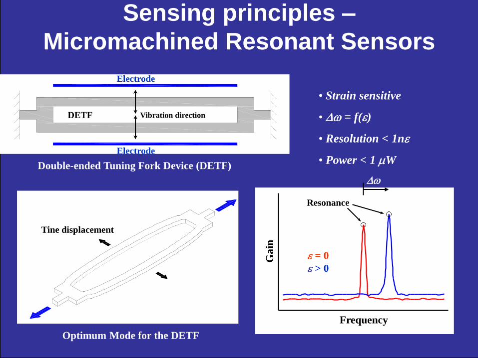
• Strain sensitive
• = f()
• Resolution < 1n
• Power < 1 mW
Optimum Mode for the DETF
Double-ended Tuning Fork Device (DETF)
Electrode
DETF
Electrode
Vibration direction
Frequency
Ga
in
Resonance
= 0
> 0
Tine displacement
Sensing principles –
Micromachined Resonant Sensors

Resonator sensor interface
oscillator output
Energy input
dissipated
energy
dissipated
energy
Transducer
physical/chemical stimulus
-140
-130
-120
-110
-100
-90
-80
-70
-60
10.753 10.7535 10.754 10.7545 10.755
Frequency [MHz]
Sp
ec
tra
l D
en
sit
y [
dB
c/H
z]
F-/A-/D
conversion

ASIC power dissipation
The oscillator core is designed to sink about 200mA current @3.3V supply.
Motional impedances under 15 kohm to meet GSM noise specification.
B. Bahreyni et al, 2007

Allan Deviation
0.1
1
10
100
1000
0.1 1 10 100 1000
INTEGRATION TIME (s)
ALLA
N D
EV
IA
TIO
N (
PP
B) TCXO (Agilent 33220A)
MEMS SE mode
Lee et al, EDL, 2008

Long-Term Stability
Rob Candler, 2005

STRAIN SENSORS

MEMS Resonant Strain Gauges
• Multi-axis sensing of strain
• Temperature compensation
• Capped under vacuum
• Polysilicon surface micromachining

Strain sensor response
Wall crack
Steel strip
Wall anchors PCB (wireless
unit/sensor
interface) Silicon chip
Uniaxial strain sensors
• Strain resolution: 23 p in 1 Hz
• Scale factor: 150 Hz/m
Collaboration with CNR Italy

FIELD DEPLOYMENT
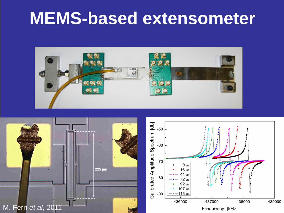
MEMS-based extensometer
225 µm
M. Ferri et al, 2011

Temperature compensation
M. Ferri et al, 2010

Deployment in Prague Metro
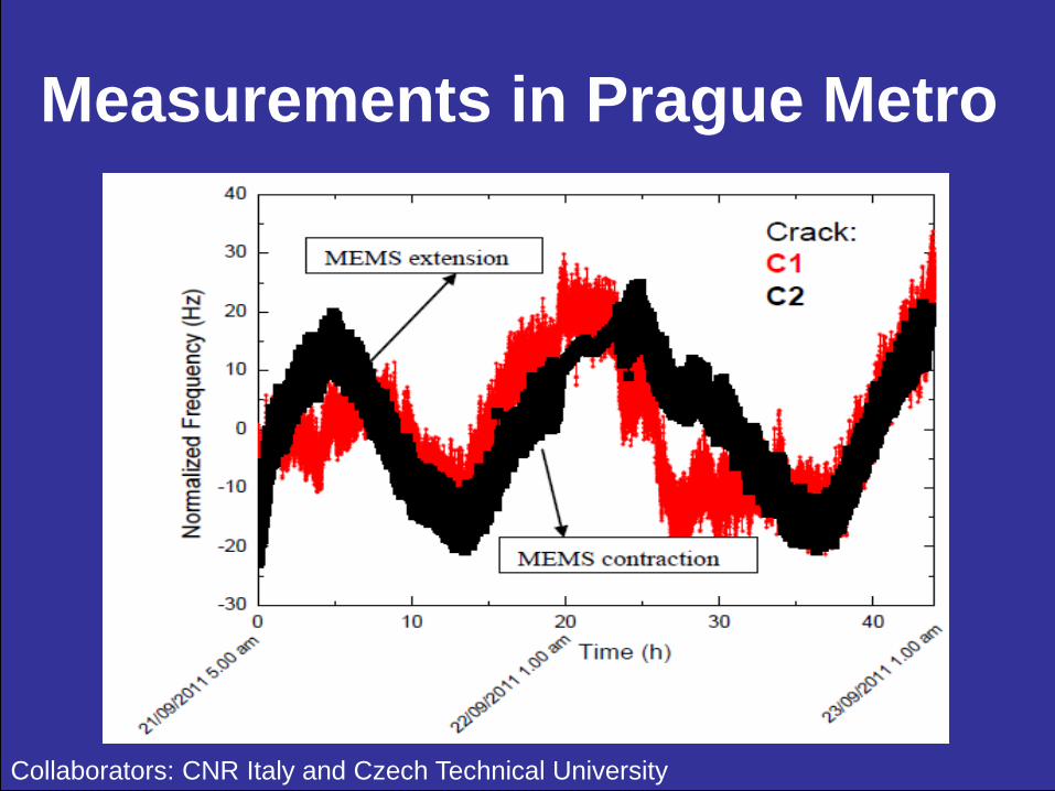
Measurements in Prague Metro
Collaborators: CNR Italy and Czech Technical University

TILT SENSORS

Micro-Electro-Mechanical
Resonant Tilt Sensor
DETF_2
DETF_1
q
Tilt Axis
Z
Freq.1
Increase
Freq.2
Decrease
F≈Mproofg
*sinθ
Tensile
Stress
Compress
Stress
X. Zou et al, 2012

Micro-Electro-Mechanical
Resonant Tilt Sensor
X. Zou et al, 2012

ENVIRONMENTAL IMMUNITY

Introduction – Vibration mode
localization • Consider an array of identical vibratory masses coupled through
weak springs –
• Irregularities inhibit propagation of vibration causing vibration
localization.
• Extent of localization depends on
– magnitude of induced disorder
– Strength of coupling spring with weaker springs leading to
greater localization.
Device 1 Device 2 Weak coupling Perfectly
symmetric When
perturbed
L+LL
M
LL
M M MInitially m1=m2; k1=k2
P. Thiruvenkatanathan et al, 2010.

Common mode rejection
• An important sensor metric – minimizing sensitivity of the sensor
to unwanted variables (for e.g..: environmental drift).
• Various compensation techniques are usually required in most
MEMS devices.
• Mode localization provides outputs that are nearly 1000 times
more sensitive to the measurand but are also relatively
insensitive to environmental drift.
• Since eigenstates are deduced from the relative amplitudes of
vibration of both nearly identical devices any effects on stiffness
and / or mass due to envtal drifts affect both simultaneously.
Device 1 Device 2 Weak coupling )2,1(;
40
i
k
k
u
u
ci
i
)2,1(;40
i
m
k
k
m
u
u
ci
i
P. Thiruvenkatanathan et al, 2010.

Intrinsic common mode rejection
The variations in the eigenstates are studied as a function of temperature and pressure. These variations are expected to be independent to first order.
Nearly one order of magnitude more insensitive to temperature variations.
300 310 320 330 3402.0
2.5
3.0
3.5
4.0
4.5
5.0 Relative shift in first eigenstate
Relative shift in second eigenstate
Theoretical
Rela
tive v
ariations (
%)
Temperature (K)(a)
10 100 10001.0
1.5
2.0
2.5
3.0
3.5
4.0
Eig
ensta
te v
ariation (
%)
Pressure (mTorr)
Variation in first eigenstate
Variation in second eigenstate
Theoretical
(a)
P. Thiruvenkatanathan et al, IEEE Transactions on Ultrasonics, Ferroelectrics and Frequency Control, 2010.

Example: charge sensing
After calibrating and measuring initial response of the two coupled resonators, the variation in the first eigenstate were studied for varying charge input and compared with corresponding resonant frequency variations:
CHARGE INPUT
Sense port 1
Sense port 2
270.54 270.57 270.600.0
1.0m
2.0m
3.0m
4.0m
5.0m
6.0m
Tra
nsm
issio
n (
lin
ea
r s
ca
le)
Frequency (kHz)
0 fC
113 fC
188 fC
263 fC
338 fC
413 fC
489 fC
(a)
Measure responses from resonators 1 (a) and 2 (b) for varying charge input
SEM image of mode-localized electrometer
270.54 270.57 270.600.0
2.0m
4.0m
6.0m
8.0m
10.0m
Tra
nsm
issio
n (
lin
ea
r s
ca
le)
Frequency (kHz)
0 fC
113 fC
188 fC
263 fC
338 fC
413 fC
489 fC
(b)
9.0m
9.2m
9.4m
9.6m
P. Thiruvenkatanathan et al, IEEE IFCS 2010.

VIBRATION ENERGY
HARVESTING

Energy harvesting for ultra-low
power sensors
• Environmental sensors operating on scavenged energy.
• Sensor packaged for operation in harsh environments.
• Sensors embedded in low power distributed sensor networks for environmental monitoring.
• Energy harvesting from ambient mechanical, fluidic and thermal sources.
• Application context: Natural and built environments.
Wall crack
Steel strip
Wall anchors PCB (wireless
unit/sensor
interface)
Silicon chip
Uniaxial strain sensors
0 500 1000 1500 2000 25000
0.1
0.2
0.3
0.4
0.5
0.6
0.7
0.8
0.9
1x 10
-6
frequency
am
plitu
de

Real-world applications
• Intermittent, irregular and broadband nature of real vibrations.
• Arrayed linear, MDOF or non-linear approaches for vibration energy
harvesting must be considered.
• Increased device complexity for non-linear mechanisms.
Y. Jia et al, submitted to Smart Materials and Structures, 2012 (under review).

Energy Harvesting from
ambient vibration
Z. J. Wong et al, PowerMEMS 2009.

Vibration Energy Harvesting
• Aims o Converting ambient vibration to useful energy
o Self sustain low power wireless or remote systems
• Challenges o Limited power levels from conventional directly forced resonance
o Confined frequency response despite broadband nature of real vibration
Vibrational
excitation Vibrational
excitation
)(3 tFxkxxcxm m mx +cx + k (t )x +mx 3 = F (t )
Direct resonance Parametric resonance

Advantages of parametrically
excited systems
• Stores an order more energy in the system:
significantly improved mechanical-to-electrical
transduction efficiency.
• Offers non-linear resonant peaks: this widens
frequency band.
• Demonstrated:
– 10x improvement in harvested power densities.
– 3x improvement in the bandwidth for a given
order of resonance.

Numerical Models
Y. Jia et al, Energy Harvesting Network Dissemination Event, 2012

Energy harvesting comparison
Y. Jia et al, Energy Harvesting Network Dissemination Event, 2012

Measured harvested energy
Y. Jia et al, submitted to Smart Materials and Structures, 2012 (under review).

MEMS parametric harvester
Y. Jia et al, PowerMEMS 2012 (to be presented).

MEMS parametric harvester
Y. Jia et al, PowerMEMS 2012 (to be presented).

Summary
• MEMS meets many certain key requirements
for the monitoring of large-scale built
infrastructure.
• Ongoing research is addressing aspects
relating to improved accuracy, environmental
immunity, packaging/interfacing, reliability,
power dissipation and integration with energy
harvesting systems.
• Much work still remains to be done to validate
MEMS technology in real-world infrastructure
monitoring applications.

Acknowledgments
• Collaborators
– Kenichi Soga, Robert Mair, Cam
Middleton, Jim Woodhouse, Mark
Welland, Cambridge University
– Alberto Roncaglia, Matteo Ferri,
CNR-IMM, Italy
• Funding
– Engineering and Physical Sciences
Research Council
– Technology Strategy Board
– British Council
– European Science Foundation
– US Army Soldier Systems Center
– Royal Society
• Students and Post-doctoral
researchers
– Jize Yan
– Jia Yu
– Pradyumna Thiruvenkatanathan
– Xudong Zou
– Joshua Lee
– Andreja Erbes
– James Ransley
– Gary Choy
– Zi Jing Wong
– Behraad Bahreyni
– Luca Belsito