Embed Size (px)
Citation preview

WHITE PAPER MEMORY PERFORMANCE OF XEON E5-2400 BASED SYSTEMS
© Fujitsu Technology Solutions 2012 Page 1 (17)
WHITE PAPER FUJITSU PRIMERGY SERVERS MEMORY PERFORMANCE OF XEON E5-2400 (SANDY BRIDGE-EN) BASED SYSTEMS
The Xeon E5-2400 (Sandy Bridge-EN) based PRIMERGY Dual Socket models also acquire their impressive increase in performance from an enhancement of the QuickPath Interconnect (QPI) memory architecture, which has proved itself now for two generations of systems. This white paper explains the changed architectural parameters and quantifies their effect on the performance of commercial applications.
Version
1.1
2012-12-07

WHITE PAPER MEMORY PERFORMANCE OF XEON E5-2400 BASED SYSTEMS VERSION: 1.1 2012-12-07
Page 2 (17) © Fujitsu Technology Solutions 2012
Contents
Document history
Version 1.0 (2012-05-31)
Initial version
Version 1.1 (2012-12-07)
Clarification in the chapter about definition of the memory frequency
Document history ................................................................................................................................................ 2
Introduction ......................................................................................................................................................... 3
Memory architecture ........................................................................................................................................... 4
DIMM slots ...................................................................................................................................................... 4
DIMM types ..................................................................................................................................................... 5
Definition of the memory frequency ................................................................................................................ 7
BIOS parameters ............................................................................................................................................ 8
Performant memory configurations .................................................................................................................... 8
Performance Mode configurations .................................................................................................................. 8
Independent Mode configurations ................................................................................................................. 10
Symmetric memory configurations ................................................................................................................ 10
Quantitative effects on memory performance .................................................................................................. 11
The measuring tools ...................................................................................................................................... 11
Interleaving across the memory channels .................................................................................................... 12
Memory frequency ........................................................................................................................................ 13
Interleaving across the memory ranks .......................................................................................................... 13
Access to remote memory ............................................................................................................................ 15
Memory performance under redundancy ...................................................................................................... 15
Literature ........................................................................................................................................................... 17
Contact ............................................................................................................................................................. 17

WHITE PAPER MEMORY PERFORMANCE OF XEON E5-2400 BASED SYSTEMS VERSION: 1.1 2012-12-07
© Fujitsu Technology Solutions 2012 Page 3 (17)
Introduction
The current generation of Dual Socket PRIMERGY servers, which is equipped with Intel Xeon E5-2600 (Sandy Bridge-EP) and Intel Xeon E5-2400 (Sandy Bridge-EN) processors, has an increase in performance of 70% (Sandy Bridge-EP) and 40% (Sandy Bridge-EN) compared with the predecessor generation. This complies with the design goals of performance (Sandy Bridge-EP) and cost efficiency (Sandy Bridge-EN). In both cases, the increase results from a new microarchitecture with up to eight cores per processor, an improvement to the memory system and a new I/O connection via the on-chip PCIe. 32-nm manufacturing technology has been adopted from the Xeon 5600 (Westmere-EP) based predecessor generation.
The proven essential features of the memory architecture of the last two predecessor generations have been retained both for Sandy Bridge-EP and Sandy Bridge-EN. The processors have on-chip memory controllers, i.e. every processor controls a group of memory modules that has been allocated to it. The performance of this local memory access is very high. At the same time, the processor is able to provide the neighboring processor with memory content via unidirectional, serial QPI (QuickPath Interconnect) links and itself request such content. The performance of the remote access is not quite so high. This architecture with its distinction between local and remote memory access is of the NUMA (Non-Uniform Memory Access) type.
The parameters of the memory architecture have been adapted in order to meet the increased computing performance of the processors. The differences between Sandy Bridge-EP and Sandy Bridge-EN are most apparent within the scale of this adaptation. In the Sandy Bridge-EN based server class covered in this document the difference consists of an increase in the maximum memory frequency from 1333 to 1600 MHz and an increase in the maximum QPI frequency from 6.4 to 8.0 GT/s (gigatransfers per second). The most elementary indicator of memory performance, the memory bandwidth, has as a result increased for the dual socket server from about 40 to 60 GB/s. In the Sandy Bridge-EP based systems there is an additional fourth memory channel per processor and two - instead of one - QPI links between the processors. These additional measures increase the memory bandwidth further to about 80 GB/s.
A basic knowledge of memory architecture, which should be provided for the Sandy Bridge-EN based systems by this white paper, is required for the configuration of the most powerful systems possible. We are dealing with the following points here:
Due to the NUMA architecture both processors should as far as possible be equally configured with memory. The aim of this measure is for both processors to work as a rule on their local memory.
In order to parallelize and thus accelerate memory access the aim is to distribute closely adjacent areas of the physical address space across several components of the memory system. The corresponding technical term is Interleaving. Interleaving exists in two dimensions. First of all, widthwise across the three memory channels per processor. The "Performance Mode" configuration of the PRIMERGY configurator in groups of three DIMMs (Dual Inline Memory Modules) of the same type on each processor ensures optimal interleaving in this direction. There is also interleaving in the depth of the individual memory channel. The decisive memory resources for this are the so-called ranks. These are substructures of the DIMMs, in which groups of DRAM (Dynamic Random Access Memory) chips are consolidated. Individual memory access always refers to such a group.
Memory frequency influences performance and is 1600, 1333, or 1066 MHz depending on processor type, DIMM type and number. The frequency can also be reduced in favor of energy consumption using the BIOS setting. Very large memory capacities and the low-voltage energy-saving mode of the memory modules limit memory frequency. For this reason the three aspects of performance, capacity and energy consumption should be weighed up against each other.
Influencing factors are named and quantified. Quantification is done with the help of the benchmarks STREAM and SPECint_rate_base2006. STREAM measures the memory bandwidth. SPECint_rate_base2006 is used as a model for the performance of commercial applications.
Results show that the percentage influences depend on the performance of the processors. The more powerful the configured processor model, the more thoroughly the issues of memory configuration dealt with in this document should be considered.
Statements about memory performance under redundancy, i.e. with enabled mirroring or rank sparing, make up the end of this document.
WHITE PAPER MEMORY PERFORMANCE OF XEON E5-2400 BASED SYSTEMS VERSION: 1.1 2012-12-07
Page 4 (17) © Fujitsu Technology Solutions 2012
Memory architecture
This section provides an overview of the memory system in four parts. A block diagram explains the arrangement of the available DIMM slots. The available DIMM types are listed in the second section. This is followed by a section about the influences on the effective memory frequency. The fourth section deals with the BIOS parameters that affect the memory system.
DIMM slots
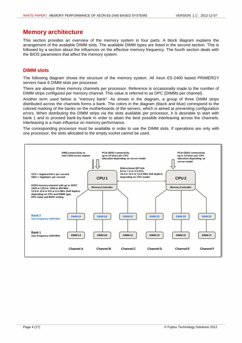
The following diagram shows the structure of the memory system. All Xeon E5-2400 based PRIMERGY servers have 6 DIMM slots per processor.
There are always three memory channels per processor. Reference is occasionally made to the number of DIMM strips configured per memory channel. This value is referred to as DPC (DIMMs per channel).
Another term used below is "memory bank". As shown in the diagram, a group of three DIMM strips distributed across the channels forms a bank. The colors in the diagram (black and blue) correspond to the colored marking of the banks on the motherboards of the servers, which is aimed at preventing configuration errors. When distributing the DIMM strips via the slots available per processor, it is desirable to start with bank 1 and to proceed bank-by-bank in order to attain the best possible interleaving across the channels. Interleaving is a main influence on memory performance.
The corresponding processor must be available in order to use the DIMM slots. If operations are only with one processor, the slots allocated to the empty socket cannot be used.
CPU 2
Memory Controller
DIMM 2D
DIMM 1D
DIMM 2E
DIMM 1E
DIMM 2F
DIMM 1F
Channel D
Bank 2max frequency 1600 MHz
Bank 1max frequency 1600 MHz
GT/s = Gigatransfers per secondGB/s = Gigabytes per second
Channel E Channel F
CPU 1
Memory Controller
DIMM 2A
DIMM 1A
DIMM 2B
DIMM 1B
DIMM 2C
DIMM 1C
Channel A Channel B Channel C
Bidirectional QPI link:8.0 or 7.2 or 6.4 GT/s16.0 or 14.4 or 12.8 GB/s (full duplex)
depending on CPU model
DDR3 memory channel with up to 3DPC1600 or 1333 or 1066 or 800 MHz12.8 or 10.6 or 8.5 or 6.4 GB/s (half duplex)
depending on CPU and DIMM type,DPC value and BIOS setting
PCIe GEN3 connectivityup to 24 lanes per CPUallocation depending on server model
DMI2 connectivity toIntel C600 series chipset
PCIe GEN3 connectivityup to 24 lanes per CPUallocation depending on
server model

WHITE PAPER MEMORY PERFORMANCE OF XEON E5-2400 BASED SYSTEMS VERSION: 1.1 2012-12-07
© Fujitsu Technology Solutions 2012 Page 5 (17)
DIMM types
DIMM strips according to the following table are considered for the memory configuration. There are unbuffered (UDIMM), registered (RDIMM) and load-reduced (LRDIMM) DIMMs. Mixed configurations consisting of these three DIMM types are not possible.
Due to their simple construction, UDIMMs have a lower maximum capacity. The simpler design entails slight advantages when it comes to price and energy consumption.
With RDIMMs the control commands of the memory controller are buffered in the register (that gave the name), which is in its own component on the DIMM. This relieves the memory channel and permits in a number of configurations a higher memory frequency than with UDIMMs, which will become evident in the next section.
Data are transferred in units of 64 bits for all DIMM types. This is a feature of DDR3-SDRAM memory technology. A memory area of this width is set up on the DIMM from a group of DRAM chips - with the individual chip being responsible for 4 or 8 bits. Such a chip group is referred to as a rank. According to the table there are DIMM types with 1, 2 or 4 ranks. The number of available ranks per memory channel has a certain influence on performance, which is explained below.
Large memory capacities, which are achieved with the newly introduced LRDIMMs, are the motivation for quad-rank DIMMs. In LRDIMMs, apart from the control commands, the data themselves are also buffered in a component to be found on the DIMM. The associated relief for the memory channel enables a memory frequency of 1333 MHz in 1DPC and 2DPC configurations. The quad-rank RDIMMs, which were foreseen in the predecessor generation for large memory capacities, were limited to 1066 MHz in 1DPC and to 800 MHz in 2DPC. A further feature of LRDIMMs, Rank Multiplication, only plays a role in the Sandy Bridge-EP based PRIMERGY servers, because 3DPC configurations only exist in these systems. A maximum of 8 ranks are supported per memory channel, which actually prevents 3DPC configurations with quad-rank DIMMs. In precisely this case, Rank Multiplication maps the 12 physical ranks onto 6 virtual ones and thus bypasses the limitation.
DIMM type (JEDEC / SystemArchitect)
Control Max fre-quency (MHz)
Volt Ranks Capa-city
Rel. price per GB
2GB 1Rx8 PC3L-12800E 2GB (1x2GB) 1Rx8 L DDR3-1600 U ECC
unbuffered 1600 1.5 / 1.35 1 2 GB 1.0
4GB 2Rx8 PC3L-12800E 4GB (1x4GB) 2Rx8 L DDR3-1600 U ECC
unbuffered 1600 1.5 / 1.35 2 4 GB 0.8
4GB 1Rx4 PC3L-10600R 4GB (1x4GB) 1Rx4 L DDR3-1333 R ECC
registered 1333 1.5 / 1.35 1 4 GB 1.1
4GB 1Rx4 PC3L-12800R 4GB (1x4GB) 1Rx4 L DDR3-1600 R ECC
registered 1600 1.5 / 1.35 1 4 GB 1.2
4GB 2Rx8 PC3L-12800R 4GB (1x4GB) 2Rx8 L DDR3-1600 R ECC
registered 1600 1.5 / 1.35 2 4 GB 1.2
8GB 2Rx4 PC3L-10600R 8GB (1x8GB) 2Rx4 L DDR3-1333 R ECC
registered 1333 1.5 / 1.35 2 8 GB 0.9
8GB 2Rx4 PC3L-12800R 8GB (1x8GB) 2Rx4 L DDR3-1600 R ECC
registered 1600 1.5 / 1.35 2 8 GB 1.0
16GB 2Rx4 PC3L-12800R 16GB (1x16GB) 2Rx4 L DDR3-1600 R ECC
registered 1600 1.5 / 1.35 2 16 GB 1.2
16GB 4Rx4 PC3L-10600L 16GB (1x16GB) 4Rx4 L DDR3-1333 LR ECC
load reduced 1333 1.5 / 1.35 4 16 GB 1.4
32GB 4Rx4 PC3L-10600L 32GB (1x32GB) 4Rx4 L DDR3-1333 LR ECC
load reduced 1333 1.5 / 1.35 4 32 GB 4.5
The decision in favor of one of the type groups UDIMM, RDIMM or LRDIMM is usually based on the required memory capacity. The performance influences of frequency and number of ranks exist in the same way for

WHITE PAPER MEMORY PERFORMANCE OF XEON E5-2400 BASED SYSTEMS VERSION: 1.1 2012-12-07
Page 6 (17) © Fujitsu Technology Solutions 2012
all three types; these influences are independent of type. Type-specific performance influences exist; but they are so minor that they can be disregarded in the majority of cases. Two examples of type-specific influences are to be given here. However, a systematic quantitative evaluation does not take place below due to insignificance:
The increasing complexity of the DIMM types UDIMM, RDIMM and LRDIMM due to additional components on the DIMM is connected with a slight increase in the access latency in the order of a few nanoseconds.
The higher load of the memory channels in the case of UDIMMs results in 2DPC configurations with this DIMM type in so-called 2N timing: address commands to the DIMM are only possible with every second clock of the memory channel. This reduces the maximum memory bandwidth by a few percent. However, an effect on application performance is improbable.
All the DIMM types on offer can be run with 1.5 V or energy-saving 1.35 V. Operation with 1.35 V can mean a reduction in the memory frequency and thus in memory performance. The following section about memory frequency sheds light on this interrelation.
The effective frequency of a given configuration depends on a series of influences. The maximum frequency stated in the DIMM type table is merely to be understood as the upper limit for this effective frequency.
The last column in the table shows the relative price differences. The list prices from May 2012 for the PRIMERGY BX920 S3 are used as a basis. The column shows the relative price per GB, standardized to the registered PC3L-12800 DIMM, size 8 GB (highlighted as measurement 1). The landscape of relative prices has been subject to constant change since the introduction of DDR3-SDRAM memory. At present, the costs for UDIMMs and for RDIMMs limited to 1333 MHz are in part somewhat lower; the new LRDIMMs are higher-priced.
Depending on the PRIMERGY model there can be restrictions regarding the availability of certain DIMM types. The current configurator is always decisive. Furthermore, some sales regions can also have restrictions regarding availability.

WHITE PAPER MEMORY PERFORMANCE OF XEON E5-2400 BASED SYSTEMS VERSION: 1.1 2012-12-07
© Fujitsu Technology Solutions 2012 Page 7 (17)
Definition of the memory frequency
There are four possible values 1600, 1333, 1066 or 800 MHz for the frequency of the memory. The frequency is defined by the BIOS when the system is switched on and applies per system, not per processor. Initially, the configured processor model is of significance for the definition. The Xeon E5-2400 models fall into three classes, each with an upper limit for the memory frequency according to the following table:
CPU type Max frequency
(MHz) QPI (GT/s) Xeon E5-2400 Processor Model
Advanced 1600 8.0 E5-2470, E5-2450, E5-2450L
Standard 1333 7.2 E5-2440, E5-2430, E5-2420, E5-2430L
Basic 1066 6.4 E5-2407, E5-2403
The DIMM type and the DPC value of the memory configuration also restrict the frequency. Processor type, DIMM type and DPC value are strong influences on the memory frequency, which cannot be overridden via BIOS. However, the BIOS parameter "DDR Performance" allows you to weigh up between performance and energy consumption. If you decide in favor of performance, the result is the effective memory frequency according to the following table:
DDR Performance = Performance optimized (Default) cells marked grey: 1.5V – without mark: 1.35V
UDIMM 1600 MHz RDIMM 1600 MHz RDIMM 1333 MHz LRDIMM 1333 MHz
CPU type 1DPC 2DPC 3DPC 1DPC 2DPC 3DPC 1DPC 2DPC 3DPC 1DPC 2DPC 3DPC
Advanced 13331 1333 n/a 1600 1600 n/a 1333 1333 n/a 1333 1333 n/a
Standard 1333 1333 n/a 1333 1333 n/a 1333 1333 n/a 1333 1333 n/a
Basic 1066 1066 n/a 1066 1066 n/a 1066 1066 n/a 1066 1066 n/a
1 1600 MHz upon special release
The following table is valid if energy-saving 1.35 V low-voltage operation is given priority:
DDR Performance = Low-voltage optimized (1.35V)
UDIMM 1600 MHz RDIMM 1600 MHz RDIMM 1333 MHz LRDIMM 1333 MHz
CPU type 1DPC 2DPC 3DPC 1DPC 2DPC 3DPC 1DPC 2DPC 3DPC 1DPC 2DPC 3DPC
Advanced 10661 1066 n/a 1333 1333 n/a 1333 1333 n/a 1066 1066 n/a
Standard 1066 1066 n/a 1333 1333 n/a 1333 1333 n/a 1066 1066 n/a
Basic 1066 1066 n/a 1066 1066 n/a 1066 1066 n/a 1066 1066 n/a
1 1333 MHz upon special release
The lowest memory performance results in the third configuration:
DDR Performance = Energy optimized (1.35V)
UDIMM 1600 MHz RDIMM 1600 MHz RDIMM 1333 MHz LRDIMM 1333 MHz
CPU type 1DPC 2DPC 3DPC 1DPC 2DPC 3DPC 1DPC 2DPC 3DPC 1DPC 2DPC 3DPC
Advanced 800 800 n/a 800 800 n/a 800 800 n/a 800 800 n/a
Standard 800 800 n/a 800 800 n/a 800 800 n/a 800 800 n/a
Basic 800 800 n/a 800 800 n/a 800 800 n/a 800 800 n/a

WHITE PAPER MEMORY PERFORMANCE OF XEON E5-2400 BASED SYSTEMS VERSION: 1.1 2012-12-07
Page 8 (17) © Fujitsu Technology Solutions 2012
So much for the description of the functionality associated with the memory frequency. Quantitative statements about the impact of memory speed on application performance are to be found below. A look-ahead to the results now follows. The setting Low-voltage optimized should be the most efficient in many productive applications, because the increase in performance that can be achieved with Performance optimized is minor (1-2%) and can only be verified with careful measurement. Low-voltage operation is largely decisive for energy savings, not so much the reduction in memory frequency. For this reason the setting Energy optimized is less interesting: whereas a reduction in memory performance is certain, further energy savings in addition to 1.35 V operations is rather uncertain.
BIOS parameters
Under Advanced / Memory in the BIOS there is a submenu relating to memory configuration with the following four parameters:
Memory Mode: Independent / Mirroring / Sparing
NUMA: enabled / disabled
DDR Performance: Low-voltage optimized / Energy optimized / Performance optimized
Patrol Scrub: enabled / disabled
The fourth parameter is an integral part of the RAS (Reliability, Availability and Serviceability) functionality and is used to remedy correctable memory errors. The default setting is enabled.
The third parameter DDR Performance was already dealt with in detail in the last section.
The NUMA parameter defines whether the physical address space is built from segments of the local memory and whether the operating system is notified about its structure. The default setting is enabled and should not be changed without a convincing reason.
The first parameter concerns the redundancy functions. If these functions are requested during the configuration in SystemArchitect, an appropriate default setting is made in the factory. Otherwise, the parameter is set to independent (no redundancy). Quantitative statements about the effect of these functions on system performance are to be found below. Performance under redundancy as well as the effect of redundancy on the maximum possible net memory capacity has improved considerably in comparison with the Xeon 5600 based predecessor systems.
Performant memory configurations
The following statements on memory configurations are based on the terminology of the PRIMERGY configurator. The first section applies to configurations that utilize the topology of the memory system in an ideal way and provide the best memory performance. The configurator refers to them as Performance Mode configurations.
Performance Mode configurations
The configuration in this mode is on a bank-by-bank basis in groups of three DIMMs of the same type, thus treating all three memory channels of a processor equally. Memory access is equally distributed over these resources of the memory system. Technically speaking, the best possible 3-way interleaving is achieved via the memory channels.
Based on the additional assumption that both processors of a 2-way server are identically configured, there are in Performance Mode 11 different memory capacities according to the following table. For a 2-way server these capacities cover a range between 12 and 384 GB. At the same time, 384 GB is the maximum memory capacity of the Xeon E5-2400 based systems.
The table is complete as regards capacities, but not necessarily so as far as the eligible DIMM types are concerned. For example, options with cost disadvantages have been omitted.

WHITE PAPER MEMORY PERFORMANCE OF XEON E5-2400 BASED SYSTEMS VERSION: 1.1 2012-12-07
© Fujitsu Technology Solutions 2012 Page 9 (17)
1 CPU system
2 CPU system
DIMM type
DIMM cap. GB Bank 1
DIMM cap. GB Bank 2
DPC value
Max MHz Performance
optimized
Max MHz Low-voltage
optimized
6 GB 12 GB UDIMM 2 1 1600 1333
12 GB 24 GB UDIMM 4 1 1600 1333
RDIMM 4 1 1600 1333
18 GB 36 GB UDIMM 4 2 2 1333 1066
24 GB 48 GB UDIMM 4 4 2 1333 1066
RDIMM 8 1 1600 1333
36 GB 72 GB RDIMM 8 4 2 1600 1333
48 GB 96 GB RDIMM 8 8 2 1600 1333
60 GB 120 GB RDIMM 16 4 2 1600 1333
72 GB 144 GB RDIMM 16 8 2 1600 1333
96 GB 192 GB RDIMM 16 16 2 1600 1333
144 GB 288 GB LRDIMM 32 16 2 1333 1066
192 GB 384 GB LRDIMM 32 32 2 1333 1066
The following diagram shows the trade-offs between memory capacity, energy savings and maximum possible memory performance, expressed by memory frequency. The diagram shows that capacity and energy savings are to a certain extent at the expense of memory performance. However, it should be recalled that the accessibility of a memory frequency also depends on the configured processor type.
800
1.066
1.333
1.600
12 24 36 48 72 96 120 144 192 288 384
Max
imu
m M
em
ory
Sp
ee
d (
MH
z)
Performance Mode Memory Capacities 2-way EN Server (GB)
DDR Performance: Performance optimized DDR Performance: Low-voltage optimized

WHITE PAPER MEMORY PERFORMANCE OF XEON E5-2400 BASED SYSTEMS VERSION: 1.1 2012-12-07
Page 10 (17) © Fujitsu Technology Solutions 2012
Independent Mode configurations
This covers all the configurations that are neither in Performance Mode nor are redundant. Apart from the rule that UDIMMs, RDIMMs und LRDIMMs may not be mixed, there are no restrictions here.
In the case of Sandy Bridge-EN based PRIMERGY servers special attention is given to classic memory sizes in powers of two, i.e. 8, 16, 32, 64 GB etc. These sizes are not covered by the ideal Performance Mode configurations that we have just considered, but by Independent Mode. This is different with the Sandy Bridge-EP based systems: due to the four (instead of three) memory channels per processor the classic memory sizes are also covered by Performance Mode.
The following table shows how the classic sizes can be realized with the Sandy Bridge-EN based servers. To denote the configurations the table uses a form of shorthand, e.g. 2-1-1, for a configuration with two DIMMs in the first memory channel and only one in the second and third channels; in each case per processor. All these configurations do not enable ideal 3-way interleaving across the memory channels and are thus associated with a certain performance disadvantage. This disadvantage is looked at in detail below in the section Interleaving across the memory channels. The configurations listed in the table are all covered by the 2-way interleaved case and are associated for commercial applications with a performance disadvantage of between 3 and 5% (compared with configurations in Performance Mode), depending on the performance of the configured processor model.
1 CPU system
2 CPU system
DIMM type
DIMM cap. UK
Configuration per CPU
DPC value
Max MHz Performance
optimized
Max MHz Low-voltage
optimized
4 GB 8 GB UDIMM 2 1-1-0 1 1600 1333
8 GB 16 GB UDIMM 4 1-1-0 1 1600 1333
RDIMM 4 1-1-0 1 1600 1333
16 GB 32 GB RDIMM 8 1-1-0 1 1600 1333
32 GB 64 GB RDIMM 8 2-1-1 2 1600 1333
64 GB 128 GB RDIMM 16 2-1-1 2 1600 1333
128 GB 256 GB LRDIMM 32 2-1-1 2 1333 1066
Apart from achieving a classic memory capacity, there can be another reason for Independent Mode configurations, especially those of the 1-1-0 type: namely, energy savings. Savings do not merely result from 1.35 V operation and reducing the frequency of a given memory configuration, but also as a result of minimizing the number of DIMMs. A 1-1-0 configuration can by all means lead to a balanced result as regards performance and energy consumption. On the other hand, a 1-0-0 configuration is not recommended due to inadequate performance.
Symmetric memory configurations
Finally, a separate section is to once again highlight that in a 2-way server both processors are to be equally configured with memory if possible and the NUMA = enabled default setting of the BIOS is not to be changed without a convincing reason. Only in this way is the QPI-based microarchitecture of the systems taken into consideration.
It goes without saying that preinstallation at the factory takes this circumstance into account. The ordered memory modules are distributed as equally as possible across both processors.
These measures and the related operating system support create the prerequisite to run applications as far as possible with a local, high-performance memory. The memory accesses of the processor cores are usually made to DIMM modules, which are directly allocated to the respective processor. In order to estimate what performance advantage this means, measurement results are listed in the section Access to remote memory in the event that the memory is indeed symmetrically configured, but where the BIOS option NUMA = disabled is set. Statistically, every second memory access is then made to a remote memory. The possible case for asymmetric or single-sided memory configuration that an application is run 100% with a remote memory should be estimated at the double loss in performance of the 50/50% case.

WHITE PAPER MEMORY PERFORMANCE OF XEON E5-2400 BASED SYSTEMS VERSION: 1.1 2012-12-07
© Fujitsu Technology Solutions 2012 Page 11 (17)
Quantitative effects on memory performance
After the functional description of the memory system with qualitative information, we now have specific statements about with which gain or loss in performance differences are connected in the memory configuration. As a means of preparation the first section deals with the two benchmarks that were used to characterize memory performance.
This is followed - in order of their impact - by the already mentioned features interleaving of the memory channels, memory frequency and interleaving of the ranks. At the end we then have measurements for the case of NUMA = disabled and memory performance under redundancy.
The quantitative testing was in each case performed separately for the processor classes Advanced, Standard and Basic. The measurements were made on a PRIMERGY BX920 S3. The processor Xeon E5-2470 was used to represent the processor class Advanced, Xeon E5-2440 for Standard and Xeon E5-2407 for Basic.
One essential result of the testing should be made clear from the very beginning. The more powerful the processor model that is used, the greater the performance influence and the more carefully you should weigh up the configuration details. Considerations that are imperative for the most powerful and most expensive processors of the Advanced class are frequently negligible for the Basic class.
The measuring tools
Measurements were made using the benchmarks STREAM and SPECint_rate_base2006.
STREAM Benchmark
STREAM Benchmark from John McCalpin [L3] is a tool to measure memory throughput. The benchmark executes copy and calculation operations on large arrays of the data type double and it provides results for four access types: Copy, Scale, Add and Triad. The last three contain calculation operations. The result is always a throughput that is specified in GB/s. Triad values are quoted the most. All the STREAM measurement values specified in the following to quantify memory performance are based on this practice and are GB/s for the access type Triad.
STREAM is the industry standard for measuring the memory bandwidth of servers, known for its ability to put memory systems under immense stress using simple means. It is clear that this benchmark is particularly suitable for the purpose of studying effects on memory performance in a complex configuration space. In each situation STREAM shows the maximum effect on performance caused by a configuration action which affects the memory, be it deterioration or improvement. The percentages specified below regarding the STREAM benchmark are thus to be understood as bounds for performance effects.
The memory effect on application performance is differentiated between the latency of each access and the bandwidth required by the application. The quantities are interlinked, as real latency increases with increasing bandwidth. The scope in which the latency can be "hidden" by parallel memory access also depends on the application and the quality of the machine codes created by the compiler. As a result, making general forecasts for all application scenarios is very difficult.
SPECint_rate_base2006
The Benchmark SPECint_rate_base2006 was added as a model for commercial application performance. It is part of SPECcpu2006 [L4] from Standard Performance Evaluation Corporation (SPEC). SPECcpu2006 is the industry standard for measuring system components processor, memory hierarchy and compiler. According to the large volume of published results and their intensive use in sales projects and technical investigations this is the most important benchmark in the server field.
SPECcpu2006 consists of two independent suites of individual benchmarks, which differ in the predominant use of integer and floating-point operations. The integer part is representative for commercial applications and consists of 12 individual benchmarks. The floating-point part is representative for scientific applications and contains 17 individual benchmarks. The result of a benchmark run is in each case the geometric mean of the individual results.
A distinction is also made in the suites between the speed run with only one process and the rate run with a configurable number of processes working in parallel. The second version is evidently more interesting for servers with their large number of processor cores and hardware threads.
And finally a distinction is also made with regard to the permitted compiler optimization: for the peak result the individual benchmarks may be optimized independently of each other, but for the more conservative

WHITE PAPER MEMORY PERFORMANCE OF XEON E5-2400 BASED SYSTEMS VERSION: 1.1 2012-12-07
Page 12 (17) © Fujitsu Technology Solutions 2012
base result the compiler flags must be identical for all benchmarks, and certain optimizations are not permitted.
This explains what SPECint_rate_base2006 is about. The integer suite was selected, because commercial applications predominate in the use of PRIMERGY servers.
A measurement that is compliant with the regulations requires three runs, and the mean result is evaluated for each individual benchmark. This was not complied with in the technical investigation described here. To simplify matters only one run was performed at all times.
Interleaving across the memory channels
Interleaving across the memory channels means the set-up of the physical address area by alternating between the three channels of a processor: the first 64 bytes – this is the so-called cache line size, the unit of memory accesses from the viewpoint of the processor – are in the first channel, the second in the second, etc. Memory access, which according to the locality principle is mainly to adjacent memory areas, is thus distributed across all channels. This performance gain situation results from parallelism.
The following table shows the performance disadvantage in the event that the ideal 3way- interleaving, which is achieved with memory configurations in Performance Mode, is not given. The table clearly shows the already highlighted fact that the performance influence (see the results with SPECint_rate_base2006) is more significant the more powerful the processor.
There may be good reasons for 2-way interleaving with a moderate loss in performance: a low memory capacity that is needed, the classic memory sizes in powers of two or minimization in the number of DIMMs in order to save energy. We advise against 1-way interleaving, which is not strictly speaking interleaving and is only referred to as such for the sake of the systematics involved. In this case, the performance potential of processors and memory system are not in a well-balanced relationship to each other.
The statements about SPECint_rate_base2006 are representative for the commercial application performance. The relationships of the memory bandwidth as expressed by STREAM should be understood as extreme cases, which cannot be ruled out in certain application areas, especially in the HPC (High-Performance Computing) environment. There is also one (libquantum) among the 12 individual benchmarks of SPECint_rate_base2006, which behaves approximately like STREAM. However such behavior is improbable for most commercial loads. This assessment of the interpretation quality of STREAM and SPECint_rate_base2006 not only applies for the performance aspect dealt with in this section, but also for all following sections.
Benchmark Processor
type 3-way 2-way 1-way
STREAM
Advanced 1.00 0.76 0.38
Standard 1.00 0.74 0.38
Basic 1.00 0.71 0.36
SPECint_rate_base2006
Advanced 1.00 0.95 0.78
Standard 1.00 0.95 0.80
Basic 1.00 0.97 0.87
In the event of memory configurations in Independent Mode it is possible for there to be a distinction in the partial capacities available for each memory channel (GB per channel). Examples here are configurations with DIMMs of a different size or configurations with four and more DIMMs of the same size. Then a single processor-local address space segment cannot be set up by alternating across the memory channels. The alternating must always "work out even". This problem is solved by splitting the physical address space into several segments with different interleaving. The memory performance of an application can then vary, depending on the segment from which the application is provided with memory.
In sensitive application cases this phenomenon may be a reason for avoiding different partial capacities per memory channel.

WHITE PAPER MEMORY PERFORMANCE OF XEON E5-2400 BASED SYSTEMS VERSION: 1.1 2012-12-07
© Fujitsu Technology Solutions 2012 Page 13 (17)
Memory frequency
The influences on the effective memory frequency have been dealt with in detail above. Energy savings and large memories can be reasons that the effective frequency is lower than is supported by the processor type and DIMM type.
The following table should be helpful when it comes to weighing up these influences against each other. The quantitative statements of the table are normalized in each case to the maximum possible memory frequency for a processor type.
The 800 MHz frequency only arises if the BIOS is changed to the setting DDR Performance = Energy optimized. However, a futher energy-saving potential beyond the setting DDR Performance = Low-voltage optimized is very low. Therefore, the 800 MHz memory frequency is not recommended. The Low-voltage optimized setting results in a frequency with 1333 or 1066 MHz.
If a reduced memory frequency is connected to the memory capacity, one issue should for the sake of completeness also be mentioned. The memory capacity can have an implicit influence on application performance, for example in the form of I/O rates. Such an influence is of course not taken into account in the testing on which this section is based. In the comparisons in the table the different memory frequency is the only influence on performance.
Benchmark Processor
type 1600 MHz 1333 MHz 1066 MHz 800 MHz
STREAM
Advanced 1.00 0.92 0.77 0.57
Standard 1.00 0.88 0.66
Basic 1.00 0.78
SPECint_rate_base2006
Advanced 1.00 0.98 0.92 0.86
Standard 1.00 0.95 0.90
Basic 1.00 0.96
Interleaving across the memory ranks
The method of alternating across memory resources when setting up the physical address space can be continued from interleaving across the memory channels to interleaving across the ranks in a channel.
Rank interleaving is controlled directly via address bits. The bit arithmetic performed in channel interleaving to establish the 3-way case is not carried out. For this reason only interleaving in powers of two comes into question, i.e. there is only a 2-way, 4-way or 8-way rank interleave. An odd number of ranks in the memory channel always results in the 1-way interleave, which is only referred to as interleave for the sake of the systematics involved: in the case of 1-way a rank is utilized to the full before changing to the next one.
The granularity of the rank interleaving is larger than with interleaving across the channels. The latter was geared to the 64-byte cache line size. Rank interleaving is oriented towards the 4 KB page size of the operating systems and is connected to the physics of DRAM memory. Memory cells are - to put it roughly - arranged in two dimensions. A row (so-called page) is opened and then a column item is read. While the page is open, further column values can be read with a much lower latency. The rougher rank interleaving is attuned to this feature.
The number of ranks per memory channel follows from the table of DIMM types and the DPC value of the configuration. The type table already shown above is repeated here again for the sake of clarity.
The performance table is related to a 4-way interleaving. This case is a given in most standard benchmarks for PRIMERGY servers. 2DPC configurations with larger RDIMMs usually provide the best balance between memory capacity and performance. The 8-way interleave, which can only occur in 2DPC configurations with LRDIMMs, results in no measureable improvement compared with the 4-way interleave and was omitted.
2-way and 4-way rank interleaving provides very good memory performance. The minute additional advantage of 4-way interleaving only plays a role if we are dealing with the very last ounce of performance. It can usually be ignored. However, the 1-way case occurs with 1DPC configurations with single-rank 2 GB UDIMMs or 4 GB RDIMMs. You should be fully aware of a certain disadvantage in performance here. This case should be avoided in sensitive applications.

WHITE PAPER MEMORY PERFORMANCE OF XEON E5-2400 BASED SYSTEMS VERSION: 1.1 2012-12-07
Page 14 (17) © Fujitsu Technology Solutions 2012
Benchmark Processor
type 4-way 2-way 1-way
STREAM
Advanced 1.00 0.99 0.95
Standard 1.00 1.00 0.98
Basic 1.00 1.00 0.94
SPECint_rate_base2006
Advanced 1.00 1.00 0.97
Standard 1.00 1.00 0.97
Basic 1.00 1.00 0.99
DIMM type (JEDEC / SystemArchitect)
Control Max fre-quency (MHz)
Volt Ranks Capa-city
Rel. price per GB
2GB 1Rx8 PC3L-12800E 2GB (1x2GB) 1Rx8 L DDR3-1600 U ECC
unbuffered 1600 1.5 / 1.35 1 2 GB 1.0
4GB 2Rx8 PC3L-12800E 4GB (1x4GB) 2Rx8 L DDR3-1600 U ECC
unbuffered 1600 1.5 / 1.35 2 4 GB 0.8
4GB 1Rx4 PC3L-10600R 4GB (1x4GB) 1Rx4 L DDR3-1333 R ECC
registered 1333 1.5 / 1.35 1 4 GB 1.1
4GB 1Rx4 PC3L-12800R 4GB (1x4GB) 1Rx4 L DDR3-1600 R ECC
registered 1600 1.5 / 1.35 1 4 GB 1.2
4GB 2Rx8 PC3L-12800R 4GB (1x4GB) 2Rx8 L DDR3-1600 R ECC
registered 1600 1.5 / 1.35 2 4 GB 1.2
8GB 2Rx4 PC3L-10600R 8GB (1x8GB) 2Rx4 L DDR3-1333 R ECC
registered 1333 1.5 / 1.35 2 8 GB 0.9
8GB 2Rx4 PC3L-12800R 8GB (1x8GB) 2Rx4 L DDR3-1600 R ECC
registered 1600 1.5 / 1.35 2 8 GB 1.0
16GB 2Rx4 PC3L-12800R 16GB (1x16GB) 2Rx4 L DDR3-1600 R ECC
registered 1600 1.5 / 1.35 2 16 GB 1.2
16GB 4Rx4 PC3L-10600L 16GB (1x16GB) 4Rx4 L DDR3-1333 LR ECC
load reduced 1333 1.5 / 1.35 4 16 GB 1.4
32GB 4Rx4 PC3L-10600L 32GB (1x32GB) 4Rx4 L DDR3-1333 LR ECC
load reduced 1333 1.5 / 1.35 4 32 GB 4.5

WHITE PAPER MEMORY PERFORMANCE OF XEON E5-2400 BASED SYSTEMS VERSION: 1.1 2012-12-07
© Fujitsu Technology Solutions 2012 Page 15 (17)
Access to remote memory
Solely a local memory was used in the previously described tests with the benchmarks STREAM and SPECint_rate_base2006, i.e. the processor accesses DIMM modules of its own memory channels. Modules of the neighboring processor are not accessed or are hardly accessed via the QPI link. This situation is representative, insofar as it also exists for the majority of memory accesses of real applications thanks to NUMA support in the operating system and system software.
The following table shows the effect of the BIOS setting NUMA = disabled in the case of an otherwise ideal memory configuration, i.e. a 4-way rank-interleaved Performance Mode configuration with RDIMMs under the highest possible memory frequency per processor. The deterioration in performance occurs because statistically every second memory access is to a remote DIMM, i.e. a DIMM allocated to the neighboring processor, and the data must make a detour via the QPI link.
Benchmark Processor
type NUMA = enabled NUMA = disabled
STREAM
Advanced 1.00 0.57
Standard 1.00 0.59
Basic 1.00 0.62
SPECint_rate_base2006
Advanced 1.00 0.89
Standard 1.00 0.90
Basic 1.00 0.93
In the case described the physical address space is set up by means of a fine-mesh alternating between the processors. This alternating presumes the same memory capacity in both processors. If this general condition does not exist, the address space is then split into a main part, which permits the inter-socket interleaving, and a processor-local remaining part.
The experiment with the setting NUMA = disabled was performed to a lesser extent because of the exceptional cases, in which this setting is recommended, because the NUMA support in system software or system-related software is missing or unsatisfactory. The experiment is above all useful in estimating the effect when most or all accesses are to remote memory. This case can occur if a processor is configured with no memory at all, or the memory capacities configured per processor differ greatly. The loss in performance compared with local access can then be up to twice the amount of the loss specified in the table.
Memory performance under redundancy
There are two redundancy options for the Xeon E5-2400 based PRIMERGY servers. For mirroring two memory channels of a processor are configured, but the one channel mirrors the other. The third channel remains empty. 50% of the actually configured memory is available to the operating system. For sparing, or more precisely rank sparing, one rank per memory channel is the unused reserve in case an active rank fails because of a faulty DRAM chip. The net memory capacity available for the operating system depends in this case on the DIMM type and DPC value.
The table shows the effect if the redundancy options are activated in the event of an otherwise ideal memory configuration, i.e. a 4-way rank-interleaved Performance Mode configuration with RDIMMs under maximum memory frequency in each case.
Benchmark Processor
type No redundancy Rank Sparing Mirroring
STREAM
Advanced 1.00 0.95 0.57
Standard 1.00 0.98 0.60
Basic 1.00 0.94 0.59
SPECint_rate_base2006
Advanced 1.00 0.97 0.87
Standard 1.00 0.97 0.91
Basic 1.00 0.99 0.95

WHITE PAPER MEMORY PERFORMANCE OF XEON E5-2400 BASED SYSTEMS VERSION: 1.1 2012-12-07
Page 16 (17) © Fujitsu Technology Solutions 2012
As shown above in the section Interleaving across the ranks, the Sparing column is identical with the 1-way rank interleaving, because a reserve rank always results in an odd number of active ranks. And as shown above in the section Interleaving across the memory channels, the Mirroring column is on the other hand not identical with the 1way- interleaving, because both halves of the mirror can be used for the read access.
A comparison with the appropriate test result for the Xeon 5600 based predecessor generation [L5] shows that the efficiency of the redundancy functions has appreciably improved.

WHITE PAPER MEMORY PERFORMANCE OF XEON E5-2400 BASED SYSTEMS VERSION: 1.1 2012-12-07
© Fujitsu Technology Solutions 2012 Page 17 (17)
Literature
[L1] PRIMERGY Systems
http://primergy.com/
[L2] PRIMERGY Performance
http://www.fujitsu.com/fts/products/computing/servers/primergy/benchmarks/
[L3] STREAM Benchmark
http://www.cs.virginia.edu/stream/
[L4] SPECcpu2006 Benchmark
http://docs.ts.fujitsu.com/dl.aspx?id=1a427c16-12bf-41b0-9ca3-4cc360ef14ce
[L5] Memory Performance of Xeon 5600 (Westmere-EP) based Systems
http://docs.ts.fujitsu.com/dl.aspx?id=f622cc5b-c6f4-41c5-ae86-a642b4d5d255
Contact
FUJITSU
Website: http://www.fujitsu.com/
PRIMERGY Product Marketing
mailto:[email protected]
PRIMERGY Performance and Benchmarks
mailto:[email protected]
All rights reserved, including intellectual property rights. Technical data subject to modifications and delivery subject to availability. Any liability that the data and illustrations are complete, actual or correct is excluded. Designations may be trademarks and/or copyrights of the respective manufacturer, the use of which by third parties for their own purposes may infringe the rights of such owner. For further information see http://ts.fujitsu.com/terms_of_use.html
2012-12-07 WW EN Copyright © Fujitsu Technology Solutions 2012