Embed Size (px)
Citation preview

Memory-AssistedMeasurement-Device-Independent
Quantum Key Distribution Systems
by
Christiana Panayi
Submitted in accordance with the requirementsfor the degree of Doctor of Philosophy
The University of LeedsSchool of Electronic and Electrical Engineering
March 2016

DeclarationsThe candidate confirms that the work submitted is her own, except where work which hasformed part of a jointly authored publication has been included. The contribution of thecandidate and the other authors to this work has been explicitly indicated below. The can-didate confirms that appropriate credit has been given within the thesis where referencehas been made to the work of others. The material contained in the chapters of this the-sis has been previously published in research articles written by the author of this work(Christiana Panayi). The research has been supervised and guided by Dr. Mohsen Razavi,and he appears as a co-author on these articles. All the material included in this documentis of the author’s entire intellectual ownership.
The work in Chapter 4 of the thesis has appeared in publication as follows:
C. Panayi, M. Razavi, X. Ma, and N. Lutkenhaus, Memory-assisted measurement-device-independent quantum key distribution New J. Phys. 16 04300 (2014). I have analyzed the systemby calculating the secret key rate when quantum memories are introduced in the memory-assisted-device-independent quantum key distribution protocol, in terms of coherence time, loading timeand key generation rate versus distance.
C. Panayi and M. Razavi, Measurement-device-independent quantum key distribution with im-perfect quantum memories. International Conference on Quantum, Nano and Micro-Technologies,
Rome, Italy, Aug. 2012.
C. Panayi, M. Razavi, X. Ma, and N. Lutkenhaus, Memory-assisted measurement-device-independent quantum key distribution. QCrypt 2013, 3rd international conference on quantum
cryptography, in Waterloo, Canada, August, 2013. It has also been presented in the International
Workshop on Quantum Communication Networks, Leeds, UK, January, 2014.
N. Lo Piparo, C. Panayi, M. Razavi, X. Ma, and N. Lutkenhaus, Reaching beyond existingquantum key distribution links: How to take advantage of imperfect quantum memories. QCrypt
2014, 4th international conference on quantum cryptography, in Paris, September, 2014.
i
N. Lo Piparo, M. Razavi and C. Panayi, Measurement-device-independent quantum key distri-bution with ensemble-based memories. IEEE Journal of Selected Topics in Quantum Electronics
vol. 21, article 3, (2015). I have contributed to the development of EPR based memory-assistedsystems.
M. Razavi, N. Lo Piparo, C. Panayi, X. Ma, and N. Lutkenhaus, Quantum Memories inAction. Invited Paper to Quantum Information and Measurement Conf., Messes Berlin, Berlin
Germany (2014). My contribution to this work is related to how quantum memories, change theperformance of the key generation rate in the measurement-device-independent quantum keydistribution protocol using EPR sources.
Some of the work in Chapters 3 and 4 of the thesis has appeared in publication as follows:
M. Razavi, C. Panayi, N. Lo Piparo and D. E. Bruschi, Architectural considerations in hybridquantum-classical networks. Invited paper to the IEEE’s Iran Workshop on Commun. and Inf.
Theory, Tehran, Iran (2013).
Some of the work in Chapter 5 has appearead in publication as follows:
M. Razavi, C. Panayi, N. Lo Piparo and X. Ma, and N. Lutkenhaus, Recent progress inmemory-assisted measurement-device-independent QKD. Invited talk to Trustworthy Quantum
Information, Michigan, USA (2015).
This copy has been supplied on the understanding that it is copyright material and that noquotation from the thesis may be published without proper acknowledgement.
©2016 The University of Leeds and Christiana Panayi
ii

AcknowledgementsMy heartfelt gratitude to Dr. Mohsen Razavi for his invaluable guidance, patience, motivation
and knowledge during my studies and his support and understanding on a personal level.My deepest appreciation goes to Aryana for his unremitting encouragement. Put simply, I
have never met anyone who believes in me more. Thank you for making me more than I am.I would especially like to thank some of my dear friends George Constantinou, Neofytos
Ioannou, Electra Eleftheriadou and Shima Ghasemi-Roudsari. We have been friends for manyyears and your love and support has kept me strong and focused on my goal.
George we have had great memories during our undergraduate studies and kept a wonderfulfriendship since then. I will always be thankful for the fruitful conversations we had regardingphysics and beyond. Neo you have taught me how to take risks and to be bold in my decisions.Electra thank you for being an understanding source of love and Shima thank you for yourguidance and standing by me all these years. Nicolo thank you for being such a good friend and afellow colleague. The discussions we had were fruitful and I am grateful for your help.
Above and beyond all, my indebtedness towards my parents and sisters for their much neededsupport, patience, understanding, and encouragement in every possible way. Their endless love,priceless, perpetual and indispensable help made all this possible. Evi thank you for alwaysbelieving in me and being there for me. Caterina I could not be more happy to have you as mysupportive and loving sister. My dear mother Nedi, thank you for being a constant source of love,concern and strength all these years. A special thanks to my father Georgios whom has alwaystaught me to go after my dreams, be strong and not let anything get between me and my goals.
This research was supported in part by the European Community’s Seventh FrameworkProgramme Grant Agreement 277110 and the UK Engineering and Physical Sciences ResearchCouncil Grant No. EP/J005762/1.
iii

Dedicated to my parents and sisters.
iv

AbstractQuantum key distribution (QKD) is one of the most prominent methods for secure exchange
of cryptographic keys between two users. The laws of physics provide it with an immense tooltowards secure communications. Although QKD has been proven to reach distances on the orderof a few hundreds of kilometers, the transmission rate of the key significantly drops when we goto further distances. One possible solution to this is to build a network of trusted nodes. The trustrequirement will however narrow its scope of deployability. In this thesis, we focus on improvingthe key rate performance of secure communications by introducing imperfect quantum memories(QMs) in a measurement-device-independent (MDI) QKD system.
In this thesis, a protocol with the potential of beating the existing distance records for conven-tional QKD systems is proposed. It borrows ideas from quantum repeaters by using memories inthe middle of the link, and that of MDI-QKD, which only requires optical source equipment atthe user’s end. For certain fast memories, our scheme allows a higher repetition rate than that ofquantum repeaters, thereby requiring lower coherence times. By accounting for various sourcesof nonideality, such as memory decoherence, dark counts, misalignment errors, and backgroundnoise, as well as timing issues with memories, we develop a mathematical framework within whichwe can compare QKD systems with and without memories. In particular, we show that with thestate-of-the-art technology for quantum memories, it is possible to devise memory-assisted QKDsystems that, at certain distances of practical interest, outperform current QKD implementations.
To extend this work, we consider a suitable candidate that fullfils the requirements we haveset for the QMs, i.e., the ensemble-based QMs. This type of memories, nevertheless, suffersfrom multiple-excitation effects, which can deteriorate the performance of the memory-assistedMDI-QKD system. As a solution we propose an alternative approach to the memory-assistedMDI-QKD by employing entangled-photon sources. We fully analyse this system by includingmodulation errors during the state-preparation at a single-photon source. We identify underwhich regimes of operation this system outperforms present QKD implementations. Overall weobtain a realistic account of what can be done with current technologies in order to improve theperformance, in terms of rate versus distance, of QKD systems. Our findings can guide us towardimplementing larger quantum networks.
v

Contents
1 Introduction 11.1 Cryptography . . . . . . . . . . . . . . . . . . . . . . . . . . . . . . . . . . . . 2
1.2 Public-key cryptography . . . . . . . . . . . . . . . . . . . . . . . . . . . . . . 3
1.3 Secret-key cryptography . . . . . . . . . . . . . . . . . . . . . . . . . . . . . . 3
1.4 Quantum key distribution . . . . . . . . . . . . . . . . . . . . . . . . . . . . . . 4
1.4.1 Prepare-and-measure protocols . . . . . . . . . . . . . . . . . . . . . . . 5
1.4.2 Entanglement based protocols . . . . . . . . . . . . . . . . . . . . . . . 6
1.4.3 Measurement-device-independent QKD protocols . . . . . . . . . . . . . 9
1.5 Thesis overview and outline . . . . . . . . . . . . . . . . . . . . . . . . . . . . 11
2 Background 132.1 Introduction . . . . . . . . . . . . . . . . . . . . . . . . . . . . . . . . . . . . . 13
2.2 BB84 protocol . . . . . . . . . . . . . . . . . . . . . . . . . . . . . . . . . . . . 13
2.3 Decoy-state method . . . . . . . . . . . . . . . . . . . . . . . . . . . . . . . . . 15
2.4 BB84 Key Rate analysis . . . . . . . . . . . . . . . . . . . . . . . . . . . . . . 17
2.5 Ekert protocol . . . . . . . . . . . . . . . . . . . . . . . . . . . . . . . . . . . . 19
2.6 MDI-QKD protocol . . . . . . . . . . . . . . . . . . . . . . . . . . . . . . . . . 20
2.6.1 MDI-QKD key rate analysis . . . . . . . . . . . . . . . . . . . . . . . . 22
2.7 Memory-assisted MDI-QKD . . . . . . . . . . . . . . . . . . . . . . . . . . . . 23
2.8 The main contributions of this thesis . . . . . . . . . . . . . . . . . . . . . . . . 25
3 MDI-QKD with imperfect encoders 273.1 Introduction . . . . . . . . . . . . . . . . . . . . . . . . . . . . . . . . . . . . . 27
3.2 This chapter’s contribution . . . . . . . . . . . . . . . . . . . . . . . . . . . . . 28
3.3 System description . . . . . . . . . . . . . . . . . . . . . . . . . . . . . . . . . 28
3.4 Key rate analysis . . . . . . . . . . . . . . . . . . . . . . . . . . . . . . . . . . 31
vi

3.5 Numerical results . . . . . . . . . . . . . . . . . . . . . . . . . . . . . . . . . . 33
3.5.1 Rate-versus-distance . . . . . . . . . . . . . . . . . . . . . . . . . . . . 37
3.6 Conclusion . . . . . . . . . . . . . . . . . . . . . . . . . . . . . . . . . . . . . 40
4 Memory-assisted MDI-QKD 434.1 Introduction . . . . . . . . . . . . . . . . . . . . . . . . . . . . . . . . . . . . . 43
4.2 This chapter’s contibution . . . . . . . . . . . . . . . . . . . . . . . . . . . . . . 45
4.3 System description . . . . . . . . . . . . . . . . . . . . . . . . . . . . . . . . . 45
4.3.1 Protocol . . . . . . . . . . . . . . . . . . . . . . . . . . . . . . . . . . . 47
4.3.2 Component modeling . . . . . . . . . . . . . . . . . . . . . . . . . . . . 47
4.3.2.1 Sources and encoders . . . . . . . . . . . . . . . . . . . . . . 47
4.3.2.2 Channels . . . . . . . . . . . . . . . . . . . . . . . . . . . . . 47
4.3.2.3 Quantum memories . . . . . . . . . . . . . . . . . . . . . . . 48
4.3.2.4 BSM module . . . . . . . . . . . . . . . . . . . . . . . . . . . 50
4.4 Key rate Analysis . . . . . . . . . . . . . . . . . . . . . . . . . . . . . . . . . . 50
4.4.1 Key rate for single-photon sources . . . . . . . . . . . . . . . . . . . . . 51
4.4.2 Key rate for decoy states . . . . . . . . . . . . . . . . . . . . . . . . . . 53
4.4.3 Storage time . . . . . . . . . . . . . . . . . . . . . . . . . . . . . . . . 54
4.5 Numerical results . . . . . . . . . . . . . . . . . . . . . . . . . . . . . . . . . . 56
4.5.1 Coherence time . . . . . . . . . . . . . . . . . . . . . . . . . . . . . . . 56
4.5.2 Realistic examples . . . . . . . . . . . . . . . . . . . . . . . . . . . . . 58
4.6 MDI-QKD with ensemble-based memories . . . . . . . . . . . . . . . . . . . . 59
4.7 Conclusions . . . . . . . . . . . . . . . . . . . . . . . . . . . . . . . . . . . . . 63
5 Memory-assisted MDI-QKD with EPR sources 645.1 Introduction . . . . . . . . . . . . . . . . . . . . . . . . . . . . . . . . . . . . . 64
5.2 This chapter’s contribution . . . . . . . . . . . . . . . . . . . . . . . . . . . . . 65
5.3 System description . . . . . . . . . . . . . . . . . . . . . . . . . . . . . . . . . 66
5.3.1 EPR source . . . . . . . . . . . . . . . . . . . . . . . . . . . . . . . . . 66
5.4 Key rate analysis of MDI vs setup inefficiencies . . . . . . . . . . . . . . . . . . 69
5.5 Numerical results . . . . . . . . . . . . . . . . . . . . . . . . . . . . . . . . . . 72
5.6 Conclusion . . . . . . . . . . . . . . . . . . . . . . . . . . . . . . . . . . . . . 76
6 Summary and future work 78
A Loading process 80
vii

B Misalignment Parameters 82
C Butterfly operator 85
Bibliography 87
viii

AbbreviationsAbbreviations used in this thesis Full expression
BS Beam splitter
BSM Bell-state measurement
EPR Entangled photon source
FSS Fine-structure-splitting
HQC Hybrid Quantum-Classical
MDI-QKD Measurement-device-independent QKD
PBS Polarising beam splitter
PNS Photon number splitting
QBER Quantum bit error rate
QKD Quantum key distribution
QM Quantum memory
RSA Rivest, Shamir and Andleman
SPDC Spontaneous-parametric-down-conversion
WCP Weak coherent-pulses
ix

List of Figures
1.1 A prepare-and-measurement QKD protocol such as BB84 [1]. . . . . . . . . . . 6
1.2 This protocol depicts a PNS attack [2]. . . . . . . . . . . . . . . . . . . . . . . . 7
1.3 This protocol depicts an entanglement based protocol such as the Ekert91 [3]. . . 8
1.4 A generalised MDI-QKD protocol [4]. . . . . . . . . . . . . . . . . . . . . . . . 8
2.1 Schematic description of the BB84 protocol. . . . . . . . . . . . . . . . . . . . . 14
2.2 The setup for the BB84 protocol. . . . . . . . . . . . . . . . . . . . . . . . . . . 17
2.3 The MDI-QKD set up [4] . . . . . . . . . . . . . . . . . . . . . . . . . . . . . 21
2.4 The MDI-QKD using two single-photon source encoders. . . . . . . . . . . . . . 22
2.5 (a) MDI-QKD with directly heralding quantum memories. Alice and Bob usethe efficient BB84 protocol to encode and send pulses to their respective QM inthe middle of the link. At each round, each QM attempts to store the incomingpulse. Once they are both loaded, we retrieve the QMs’ states and perform aBSM on the resulting photons. (b) MDI-QKD with indirectly heralding quantummemories. At each round, an entangling process is applied to each QM, whichwould generate a photon entangled, in polarization, with the QM. These photonsinterfere at the BSM modules next to the QMs with incoming pulses from theencoders. As soon as one of these BSMs succeeds, we stop the entangling processon the corresponding QM, and wait until both QMs are ready for the middle BSMoperation. In this case, QMs are not required to be heralding; a trigger event isdeclared by the success of the BSM located between the QM and the respectiveencoder. (c) The original MDI-QKD protocol [4]. . . . . . . . . . . . . . . . . . 24
3.1 Asymmetric setup with imperfect BB84 encoders in an MDI-QKD scheme. . . . 28
3.2 Modeling of the channel loss and detection efficiency in the BSM module. . . . . 30
3.3 Bell-state measurement module for polarization states. . . . . . . . . . . . . . . 30
x

3.4 This is a comparison of the QBER-versus-distance in the Z and X basis of asymmetric setup for different fidelity values. . . . . . . . . . . . . . . . . . . . . 34
3.5 Comparison of the QBER in Z basis for a symmetric setup for different fidelityvalues using an imperfect single-photon source and an ideal single-photon source. 36
3.6 This is a comparison of the QBER-versus-distance in the X basis of a symmetricsetup for different fidelity values of the non-diagonal terms. . . . . . . . . . . . . 37
3.7 Comparison of the Rate-versus-distance for a symmetric setup for different fidelityvalues. . . . . . . . . . . . . . . . . . . . . . . . . . . . . . . . . . . . . . . . . 38
3.8 Comparison of the key rate versus distance for a symmetric setup for differentfidelity values using an imperfect single-photon source and an ideal single-photonsource. . . . . . . . . . . . . . . . . . . . . . . . . . . . . . . . . . . . . . . . . 39
3.9 Comparison of the key rate versus distance for a symmetric and an asymmetricsetup for different fidelity values using an imperfect single-photon source and anideal single-photon source. . . . . . . . . . . . . . . . . . . . . . . . . . . . . . 40
3.10 Key rate versus distance for different fidelities of the non-diagonal terms in asymmetric setup. . . . . . . . . . . . . . . . . . . . . . . . . . . . . . . . . . . 41
4.1 One possible energy-level configuration for a QM suitable for polarization encoding. 48
4.2 Average required storage time, Tst , versus distance, in our scheme, for differentrepetition rates 1/τw. As compared to that of a probabilistic quantum repeater,labeled by L/c, where c = 2×10⁸ m/s is the speed of light in optical fiber, ourscheme requires lower coherence times up to a certain distance. The crossoverdistance at τw = 1 µs is over 300 km and at τw = 1 ns is nearly 700 km. In allcurves, ηw = ηd = ηent = 1 and pBG = 0. . . . . . . . . . . . . . . . . . . . . . 55
4.3 Secret key generation rate per pulse for the heralded scheme of Figure 2.5(a) fordifferent values of T2/T using single-photon sources. The dashed line representsthe ideal efficient BB84 case. Unless explicitly mentioned, all other parametersassume their ideal values: T1 → ∞, ηw = ηr0 = ηd = 1, γBG = γdc = 0, edA =
edB = 0, and τr = 0. . . . . . . . . . . . . . . . . . . . . . . . . . . . . . . . . . 57
4.4 Secret key generation rate for different values of τw at T2/T = 1000 using single-photon sources. The dashed line represents the ideal efficient BB84 case atRS = 1 Gpulse/s. Unless explicitly mentioned, all other parameters assume theirideal values: T1→∞, ηw = ηr0 = ηd = 1, γBG = γdc = 0, edA = edB = 0, and τr = 0. 58
xi
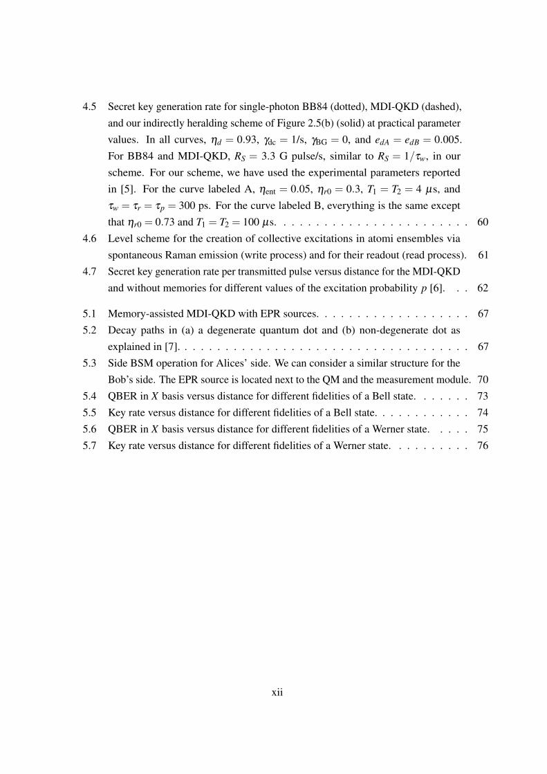
4.5 Secret key generation rate for single-photon BB84 (dotted), MDI-QKD (dashed),and our indirectly heralding scheme of Figure 2.5(b) (solid) at practical parametervalues. In all curves, ηd = 0.93, γdc = 1/s, γBG = 0, and edA = edB = 0.005.For BB84 and MDI-QKD, RS = 3.3 G pulse/s, similar to RS = 1/τw, in ourscheme. For our scheme, we have used the experimental parameters reportedin [5]. For the curve labeled A, ηent = 0.05, ηr0 = 0.3, T1 = T2 = 4 µs, andτw = τr = τp = 300 ps. For the curve labeled B, everything is the same exceptthat ηr0 = 0.73 and T1 = T2 = 100 µs. . . . . . . . . . . . . . . . . . . . . . . . 60
4.6 Level scheme for the creation of collective excitations in atomi ensembles viaspontaneous Raman emission (write process) and for their readout (read process). 61
4.7 Secret key generation rate per transmitted pulse versus distance for the MDI-QKDand without memories for different values of the excitation probability p [6]. . . 62
5.1 Memory-assisted MDI-QKD with EPR sources. . . . . . . . . . . . . . . . . . . 675.2 Decay paths in (a) a degenerate quantum dot and (b) non-degenerate dot as
explained in [7]. . . . . . . . . . . . . . . . . . . . . . . . . . . . . . . . . . . . 675.3 Side BSM operation for Alices’ side. We can consider a similar structure for the
Bob’s side. The EPR source is located next to the QM and the measurement module. 705.4 QBER in X basis versus distance for different fidelities of a Bell state. . . . . . . 735.5 Key rate versus distance for different fidelities of a Bell state. . . . . . . . . . . . 745.6 QBER in X basis versus distance for different fidelities of a Werner state. . . . . 755.7 Key rate versus distance for different fidelities of a Werner state. . . . . . . . . . 76
xii

List of Tables
C.1 Butterfly operation on input state . . . . . . . . . . . . . . . . . . . . . . . . . . 86
xiii

List of NotationsBBF Butterfly OperatorBent Entangling Operator for side-BSMBη Beam Splitter Operator with transmissivity η
B†ηα
Alice’s Hermitian Conjugate of the transmissivity BeamSplitter Operator
B†ηβ
Bob’s Hermitian Conjugate of the transmissivity Beam Split-ter Operator
c Speed of light in the channelE{·} Expectation value operator
eKBG
Probability of QM loaded by a background photon condi-tioned on successful loading
ed Total misalignment probability of the channeledeph Misalignment due to dephasing
e(A,B)dSMisalignment probabilities for Alice’s and Bob’s QMs forbasis S = {X ,Z}
ei QBER for i−photon states
Eµ
QBER for a phase-randomised coherent state with µ photonson average
EµQµ
Intrinsic error rate for a phase-randomised coherent statewith µ photons on average
EQMµν ;Z
QBER in the Z basis after successfully loading both QMswhen Alice and Bob use respectively µ and ν on averagenumber of photons
e11;SQBER in basis S={X ,Z} between Alice and Bob when sin-gle photons are used
eQM11;S
QBER in basis S={X ,Z} between Alice and Bob QMs whensingle photons are used
F Fidelity of the i−photon statef 1 Error correction inefficiency|Hxx〉 Biexciton photon of a quantum dot in horizontal polarization|Hx〉 Exciton photon of a quantum dot in horizontal polarization|H〉 Horizontally polarised photonh(x) Binary entropy functionI0(x) Modified Bessel function of the first kind
xiv

I Identity operatorLatt Attenuation length
MDiD jMeasurement Operator of two detectors in orthogonal polar-isations H,V of a successful BSM
NAGeometric random variable on Alice’s side with successprobability ηA
NBGeometric random variable on Bob’s side with success prob-ability ηB
NL Average number of trials to load both memoriesNr Extra rounds lost due to nonzero reading times of QMspBG Probability of background (unpolarized) photons per pulsepdc Probability of dark count|P〉 A polarised photon in a BB84 state
PDiD jProbability of a successful BSM where i, j are one of the 4single photodetectors
q Basis reconciliation factor
Q11
Probability of a successful BSM if Alice and Bob respec-tively send single-photon pulses multiplied by the probabilityof sending single photons
QQM11
Probability of a successful BSM after successfully loadingthe QMs with single-photon pulses multiplied by the proba-bility of sending single photons
QSAB
Probability an acceptable pattern of clicks occurs in theS= {X ,Z}
QC Probability of correct clicks occurs in the basis S= {X ,Z}
QXE
Probability of having a successful pattern of clicks due toerrors in the X basis
QZE
Probability of non-identical bits in Z basis assuming Aliceand Bob used the Z basis to encode their bits initially
Qµ
Probability of a successful BSM conditioned on using µ
average number of photons
QQMµν ;Z
Overall gain when Alice and Bob use pulses with µ and ν
average number of photonsQi Overall gain of i−photon statesR Secret key generation rateRS Single-photon repetition rateT Repetition periodT1 QM amplitude decay timeT2 Coherence or dephazing time of the QM
xv

Tst Average required memory storage time|V 〉 Vertically polarised photon
YiConditional probability of detection on Bob’s side condi-tioned that Alice sends i photons
Y1
Yield of single photons or the probability that Bob gets aclick on his measurement devices assuming Alice has sentexactly one photon
Y11
Yield of single photons or the probability of a successfulmiddle BSM assuming Alice and Bob has sent exactly onephoton
Y QM11
Rate at which both QMs are loaded with single photons ofthe same basis and the middle BSM is successful
YCYield or otherwise conditional probability of identical bitsshared by Alice and Bob
YEYield or otherwise conditional probability of non-identicalbits shared by Alice and Bob
Y QMEPR
Yield or otherwise conditional probability that heralds thesuccessful BSM conditioned on the success of the side-BSMs from both Alice’s and Bob’s sides
γBG Background rate per pulseγdc Dark count rate per pulse
µ , νAverage number of photons for the signal state in decoystate-method
ηa Channel efficiency of Alice’s sideηb Channel efficiency of Bob’s sideηA Success probability for middle-BSM on Alice’s sideηB Success probability for middle-BSM on Bob’s sideηch Channel loss efficiencyηd Detector efficiencyηent Entangling effificiencyηg EPR source efficiency
η1KProbability of successfully loading a directly heralding QMwith SPSs for the leg K = {A,B}
ηmK Effective measurement efficiency for the leg K = {A,B}ηr0 QM reading efficiency right after loadingηr QM reading efficiencyηw QM writing efficiencyτp Pulse duration
τrReading time duration, time between retrieval process untilend of the pulse
τw Writing time duration
xvi
Chapter 1
Introduction
Communication is one of the most basic and yet most essential part of human beings in their dailylives. It can be verbal exchange of information when discussing on a one-to-one basis or nonverbalby using the technological advancements with the help of networks. This communication could beextended to multiple-users all over the world. An important necessity is how to establish securecommunication between two or more parties in long distances and at the same time have high datarates. Another is authentication where users are assured that their communicating party on theother end is who they claim to be. The area that focuses strictly on how to establish these goals iscalled cryptography. Various methods and techniques based on cryptographic systems have beendeveloped to protect communicating parties from adversaries. Complexity of encryption in somealgorithms is what provides the security in communication against potential eavesdroppers, thusmaking the decryption more difficult. An equally interesting area of cryptography that providesreliable security is quantum cryptography and an application therein, quantum-key-distribution(QKD). In QKD, it is guaranteed that any eavesdropper trying to intercept the secret key canbe detected by the users. Despite the unconditional security that it offers, QKD has yet a longway to implement efficient systems that can tolerate loss. The motivation behind my work relieson the implementation of a trustworthy QKD system over long distances with characterisedimperfections in our employed devices. In order to describe the work behind this thesis, I willintroduce a basic background, which will be used as a guide to the main topics studied in thisthesis.
1

1.1 Cryptography
Cryptography, from the Greek words κρυπτ oς , meaning secret or hidden and γραφη meaningwriting, is the primary science that studies and develops methods of encryption and decryptionof messages, as well as authentication, integrity and non-repudiation in order to establish securecommunication.
Looking at the 20th century inventions of cryptography, one of the most outstanding inventionsis the one-time-pad by Vernam [8]. The principle of this cryptographic algorithm is to translateinformation, with the help of a secret key, from a plaintext to a sequence of random charactersin the alphabet, the so-called ciphertext. This symmetrical stream cipher uses a combination ofplaintext and streams of data with the same length. In the binary format, in order to generate theciphertext, we use the Boolean or otherwise known XOR function: plaintext⊕ key = ciphertext
=> ciphertext⊕ key = plaintext.
A key is generally used in cryptographic algorithms, for instance, in message authenticationcodes and digital signature schemes. The transformation from plaintext to ciphertext is calledencryption and vice versa is the decryption. With one-time-pad the information could be trustedto be transmitted publicly as the only person that could decode the ciphertext must have thesecret key. The Vernam cipher has the advantage of providing unconditional security againstadversaries with unlimited computational power; however, the distribution of the required keywas a complication. The significance of the security that it provides even nowadays is of greatimportance and we will discuss this further in key distribution.
Another innovative invention was the Enigma [9] machine by A. Schrebious in 1918, whichwas later on called the rotor machine. The rotating wired wheels could perform a challengingsubstitution cipher. It was widely used during World War II. The Enigma could have up to159× 1018 different cryptographic keys. The fact that this machine could have this enormousnumbers of possible keys is what paved the way for Alan Turing to formulate the first electroniccomputer, which in turn used to decode the Enigma cipher later on. Enigma cipher messages aredecoded in a few minutes with the current computational power.
The security of Enigma and similar encryption systems is based on the mathematical com-plexity of factorising the product of two large prime numbers. Therefore it is required to finddifferent cryptographic systems that their security is resilient to the advancement of technology incomputation power.
Cryptography has two main classes of cryptographic protocols, the public or asymmetric-keycryptography and the secret or symmetric-key cryptography. In the next sections, I give a briefdescription of their main advantages and weaknesses.
2

1.2 Public-key cryptography
Public key cryptography or otherwise asymmetric cryptography is an invention of W. Diffie and M.Hellman [10]. It is a method of assuring the authenticity and security of the Internet. Public keycryptography is based on sharing initial seed keys that will be used for cryptographic protocols,between two communicants. The user A on one end creates two different keys, hence the termasymmetric, one is public and available to everyone and the second one is a secret key, which isstored in a private place. If someone wishes to communicate with A then he/she has to use thepublic key to encrypt his/her message and then send it to A, who can decrypt it using her privatekey. This technique reassures confidentiality. Practically, the public keys are distributed throughtrusted servers. The secret key can be retrieved with the help of strong computation power sincethe secret and public key are mathematically related.
RSA cryptosystem was invented by Rivest, Shamir and Andleman [11] and is one of themost widely used examples of algorithms used by public-key cryptography. It is based on themathematical difficulty of factoring large numbers. In RSA, A picks two large prime numbers, p
and q, and announces their product publicly. He/she chooses two large numbers k and l such that(kl - 1) is divisible by (p-1) (q-1). The public key consists of the product N =pq together withthe number l; p, q and k make the private key. With N and l, anyone can encrypt a message M
by calculating S = Ml mod N. To decipher the encrypted message, A uses his/her private keyand calculates M = Sk mod N. Thus in order to break the RSA system, one has to find the primefactors of N, which is a significantly hard computational problem for classical computers.
During the past decades there have been many attempts to break an RSA system [12, 13]. In arecent attack a 768 bit key was cracked by a network of classical computers [14]. With the help ofquantum computers, the RSA system will be decrypted in polynomial order time [15]. Thereforethe RSA may become entirely outdated for its purpose. A different type of cryptography is studiedalong with its benefit of the security it provides.
1.3 Secret-key cryptography
Secret-key cryptography or else known as symmetric key are algorithms that use the samecryptographic keys to both encrypt and decrypt a message. However the distribution of the secretkey to the two parties constitutes one of the main limitations of secret key cryptography. Today,the key distribution part is done by public-key schemes. The combination of fast secret-key andversatile public-key systems, is at the core of today’s secure systems.
3
Vernam cipher [8], as previously mentioned, is an unbreakable classical cryptographic cipher,secure against eavesdroppers with unlimited computational and technological power. This sym-metric cipher, uses a random key to ensure secure communication and uses the same key for both,encrypting and decrypting a message, between two authenticated users. The encryption algorithmE in the binary logic [16] can be written as:
EN(L) = (L1 +N1,L2 +N2, ...,Ln +Nn) mod 2. (1.1)
where L = (L1,L2, ..Ln) represents the message in the form of bits and N = (N1,N2, ..Nn) repre-sents the key in the form of random bits or else the secret key bits. The decryption of the messagefollows the same procedure as in equantion (1.1), on EN . When applying the mod 2 operationtwo times then L can be retrieved as follows
L = EN(EN(L)) = (L1 +N1 +N1,L2 +N2 +N2, ...,Ln +Nn +Nn) mod 2. (1.2)
To establish an unbreakable secure one-time-pad system, three conditions need to be fulfilled:(a) the key length must be equal to the length of the message; (b) the key must be random; (c) itmust be used only once (hence the one-time pad name) as it was proved by Shannon in 1949 [17]from the information theory point of view. Even though, all of the three conditions are fulfilled,the main limitation of the Vernam cipher, is the distribution of the key when one user is in distancefrom the other. Public-key cryptography can be compromised as mentioned in Sec 1.2. However,quantum key distribution (QKD) can be used as a solution to this problem. It offers to detect aneavesdropper if he/she retains an unacceptable amount of information of the secret key, as it willbe explained next.
1.4 Quantum key distribution
QKD is based on the laws of quantum mechanics and it establishes a cryptosystem secure againstany attempt by adversaries to compromise the communication without the knowledge of thetwo autenticated users. Protocols based on the quantum mechanics principles have unbreakablesecurity, unlike classical cryptography, even against an eavesdropper with unlimited computationalpower. The basic principle behind QKD is the use of non-orthogonal quantum states. Its securityis based on the Heisenberg uncertainty principle, which states that a measured system will bealtered if someone attempts to learn information about the non-orthogonal states with certaintyand this eavesdropper would be eventually detected. In classical physics, an eavesdropper cannot
4
be traced, since the information can be encoded into any properties of a classical object and canbe accessed without changing the current state of the object [16]. Unlike the classical systems,the quantum ones, with the usage of non-orthogonal quantum states as information carriers, canreassure the inviolability of the channel. Since the information is encoded into non-orthogonalstates, it cannot be split, read or copied without disturbing the system in a detectable way [16].
Nonetheless QKD cannot prevent possible attempts for interception from adversaries; it onlyoffers the detection of any eavesdropper, namely, Eve. Any attempt of Eve to gain informationwould result in discrepancies. Therefore with the help of post-processing techniques, the key iseither made secure or discarded and the two legitimate users repeat the protocol for a new key tobe generated.
There are different QKD protocols in practise. Here, I briefly explain major categories ofprotocols pertinent to this thesis. Further detailed description of these protocols will appear inChapter 2.
1.4.1 Prepare-and-measure protocols
One of the pioneering protocols of the prepare-and-measure category is BB84 [1] (see Figure 1.1).In prepare-and-measure protocols, one user has the encoder side and the other has the decoder. InBB84 Alice sends a polarised single photon, encoded, in one of the two random chosen bases.Following this, Bob measures it respectively to determine its polarization. This procedure isrepeated multiple times until they have an adequately long string of bits. In the sifting processBob shares his chosen basis for measurement, publicly. Thus they keep the bits that share thesame basis and discard the rest. If Eve attempts to intercept the communication, e.g. the photontransmitted by Alice, then she will introduce discrepancies that can be detected in the generatedsifted keys.
In prepare-and-measure schemes, e.g., BB84 [1], they commonly rely on the transmissionof single photons between two parties. According to the no-cloning theorem [18] there cannotbe exact copies of an arbitrary quantum state without violating the laws of quantum mechanics.Thus the security of any protocol using single photons is guaranteed by the no-cloning theorem[18]. Nevertheless the implementation of single photon sources faces many difficulties. In recentyears many solutions have been proposed to overcome this drawback. One of the proposals isto, instead of ideal single-photon sources, use weak laser pulses that emit coherent states. Thesecoherent states consist of vacuum components and multiphoton components, which can causeadverse results in the performance of a QKD protocol. When the source emits more than a singlephoton this leads to a compromised security as the so-called photon number splitting (PNS) attack
5

Quantum Channel
Classical Channel
Alice Eve Bob
Figure 1.1: A prepare-and-measurement QKD protocol such as BB84 [1].Alice transmits single encoded photons to Bob through a quantum channel and they both publicly
announce the bases they used. Eve represents any eavesdropper trying to intercept thecommunication.
[2] (see Figure 1.2) offers Eve the possibility to obtain information of the key without beingtraced. However, under certain conditions, a secure key can still be established even under thePNS attack as proven in GLLP [19], but with a significant reduction of the secret key. In PNS,the rate is scaled as ηch
2, whereas the single photon source rate is scaled as ηch, where ηch is thetransmittance of the quantum channel.
Other solutions to the PNS attack, since the ideal single photon sources are not available, arethe modified BB84 [20] protocol where the key rate scales as ηch
3/2, or using decoy state protocols[21] where Alice randomly sends two types of pulses, one is used for extracting the key and theother are the so called decoy states, which are used for detection of any eavesdropper. Decoy statebased protocols can be used against PNS attacks as Eve will not be able to discriminate betweenthe signal and decoy pulses. I will be giving a further description of this in Chapter 2.
1.4.2 Entanglement based protocols
Another category of equally important protocols is based on entanglement. Quantum entanglementis a property that applies only in quantum physics thus a property that cannot be used in classicalphysical systems. Two systems are considered entangled when their joint quantum state cannotbe described as a convex sum of separable states. The most famous QKD protocols based onentanglement are Ekert91 [3] (see Figure 1.3) and BBM92 [22]. Assuming that the entangledparticles are photons and one of them is measured in the rectilinear basis, and has been foundto have a horizontal polarization then it is expected that the other photon will have a knownpolarization, conditioned that it is measured in the same basis. However, if the second photon is
6

Imperfect Photon Source
Alice Bob
Eve
Quantum Channel
Figure 1.2: This protocol depicts a PNS attack [2].In the case of an imperfect single-photon source, the PNS attack takes place in a typical QKD
protocol as shown above.
measured in a different basis, e.g. circular, then it will have either right or left circular polarization.Ekert, in his paper [3], proved that the security of a two-qubit protocol is based on Bell’s inequality[23], an inequality which states that some correlations can be predicted by quantum mechanicsbut cannot be recreated by the local hidden variable theory. John Clauser, et. al. introduced theCHSH inequality [24], with the following classical constraints on the sum of four correlations inAlice and Bob’s experiment:
−2≤ S≤ 2, (1.3)
whereS = E(a,b)−E(a′,b)−E(a,b′)+E(a′,b′), (1.4)
where a (b) and a′ (b′) represent detector settings on Alice and Bob’s side, respectively. The fourcombinations are tested separately in experiments. The terms E(a,b) are the quantum correlationsof the particle pairs. Quantum correlation is the expectation value of the product of the “outcomes”of the experiment. In quantum mechanics, the mathematical formalism predicts that S has amaximum value of 2
√2, which is greater than 2 therefore CHSH violations are confirmed by
the theory of quantum mechanics. Thus, if an adversary attempts to intercept the entangledpairs shared by Alice and Bob, he or she will break the quantum correlation of the two particles,resulting in a non-violation of Bell’s inequality.
While in entanglement-based QKD protocols, users do not need to trust the source, their mea-surement devices are still prone to many attacks by Eve. This has particularly been demonstratedexperimentally by modifying the Bob’s detector setup in commercial products. These attacksinclude the time-shift attack, remapping and blinding attacks [25, 26, 27, 28, 29, 30]. In these
7

Quantum Channel
Eve
Classical Channel
Entangled Photon Source
BobAlice
Figure 1.3: This protocol depicts an entanglement based protocol such as the Ekert91[3].
An entanglement photon source placed between Alice and Bob, emits a pair of entangled photons,one to each user through a quantum channel. As in the BB84 they discuss their measurement
results publicly.
BSM
BobEveAlice
Quantum Channel
Classical Channel
Figure 1.4: A generalised MDI-QKD protocol [4].Alice and Bob both emit single photons through a quantum channel to the middle of their link to
perform Bell-state-measurement (BSM). The BSM module could be handled by Eve and thesecret key generated can still be secure.
8

attacks, Eve exploits the flaws of the detectors to her benefit to gain information about the key.Hence, the measurement devices, apart from being of a high value, are not necessarily reliable forthe secure operation of a QKD protocol. There is, however, a counterproposal to overcome thislimitation [31, 32] as we explain next.
1.4.3 Measurement-device-independent QKD protocols
In an alternative approach to BB84 [1] and Ekert91 [3], a different generation of protocols wasproposed, the measurement-device-independent (MDI) [4] QKD. Below there is a brief descriptionof this protocol.
In the MDI-QKD (see Figure 1.4) a reversed EPR-based [33] QKD security proof is combinedwith BB84 source states. The main idea is that Alice and Bob would effectively share entangledstates pair in their own laboratory using the teleportation trick. A more detailed description ofMDI-QKD follows in Section 2.6.
In MDI-QKD type of protocols, the main goal is to close the gap between theory and practicewith varying degrees of success, as detection devices, which are the most prone to various attacks.MDI-QKD has proved to be more tolerant against device inefficiencies (i.e. detection) and lowchannel loss and yet provide secure keys. Additionally the MDI-QKD is resilient against side-channel attacks on detector setups, such as the time-shift attack [34, 35], the re-mapping attack[36] and the blinding attack [37]. Moreover, it improves the security distance over QKD protocolsthat use conventional laser diodes [4].
In a practical implementation of a QKD protocol, there are various imperfections, such asthe detection efficiency, dark counts in photodetectors, imperfect sources and channel loss. Allthese inefficiencies contribute to a constrained performance of a QKD protocol. This is usuallymeasured by the corresponding rate at which the two users can establish a secret key, i.e. thesecret key generation rate. In this thesis, I use the secret key generation rate as the main figure ofmerit for comparing the performance of different systems considered here.
Despite all commercial and experimental achievements in QKD [38, 39, 40, 41, 42], reachingarbitrarily long distances is still a remote objective. Because QKD relies on single photons togenerate secret keys, this would impose numerous problems when long-distance communicationsis concerned. Limitations such as the channel loss restricts the distance of communicationssignificantly. The fundamental solution to this problem, i.e., quantum repeaters, that is is knownfor over a decade. From early proposals by Briegel et al. [43] to the latest no-memory version byMunro et al. [44], quantum repeaters, typically rely on highly efficient quantum gates comparableto what we may need for future quantum computers. While the progress on that ground may
9

take some time before such systems become functional, another approach based on probabilistic
gate operations was proposed by Duan and coworkers [45], which could offer a simpler way ofimplementing quantum repeaters for moderate distances of up to around 1000 km. The lattersystems require quantum memory modules with high coupling efficiencies to light and withcoherence times exceeding the transmission delays, which are yet to be achieved together. In thisthesis, we propose a protocol that, although is not as scalable as quantum repeaters, for certainclasses of memories, to some extent, relaxes, the harsh requirements on memories’ coherencetimes, thereby paving the way for the existing technologies to beat the highest distance recordsachieved for no-memory QKD links [38]. The idea behind our protocol was presented in [46], and,independently, it has also been used in [47]. This thesis proposes additional practical schemes andrigorously analyzes them under realistic conditions.
Our protocol relies on concepts from quantum repeaters, on the one hand and MDI-QKDon the other. The original MDI-QKD [4] relies on sending encoded photons by the users to amiddle site at which a Bell-state measurement (BSM) is performed. This BSM can be done by anuntrusted party, e.g., the service provider, which makes MDI-QKD resilient to detector attacks,e.g., time-shift, remapping, and blinding attacks [25, 26, 27, 28, 29, 30]. The security is thenguaranteed by the reverse EPR protocol [33]. In our scheme, by using two quantum memories atthe middle site, we first store the state of the transmitted photons in the memories, and performthe required BSM, only when both memories are loaded. This way, similar to quantum repeaters,we achieve a rate-versus-distance improvement as compared to the MDI-QKD schemes proposedin [4, 48], or other conventional QKD systems that do not use quantum memories.
There is an important distinction between our protocol and a conventional quantum repeatersystem. In a typical quantum repeater link, which relies on initial entanglement distributionamong neighboring nodes, the repeat period for the protocol is mainly dictated by the transmissiondelay for the shortest segment of the repeater system [49, 50]. In our scheme, however, the repeatperiod is constrained by the writing time, including the time needed for the herald/verificationprocess, into memories. This implies that using sufficiently fast memories, one can run ourscheme at a faster rate than that of a quantum repeater, thereby achieving higher key generationrates, as compared to conventional QKD links, and at lower coherence times, as compared toprobabilistic repeater systems. This increase in clock rate is what our proposal shares with therecently proposed third generation of quantum repeaters, which use quantum error correctioncodes to compensate for loss and errors, thus also being able to speed up the clock rate to localprocessing times [44]. The need for long coherence times remains one of the key challenges inimplementing the first generations of quantum repeaters before the latest no-memory quantum
10

repeater proposals can be implemented.
The above two benefits would offer a midterm solution to the problem of long-distance QKD.While our scheme is not scalable the same way that quantum repeaters are, it possibly allows us touse the existing technology for quantum memories to improve the performance of QKD systems.In the absence of fully operational quantum repeater systems, our setup can fill the gap betweentheory and practice and will become one of the first applications of realistic quantum memories inquantum communications.
It is worth mentioning that the setups we propose here are compatible with different generationsof hybrid quantum-classical (HQC) networks [51]. In such systems, home users are not only ableto use broadband data services, but they can also use quantum services such as QKD. MDI-QKDoffers a user-friendly approach to the access part of such networks as the end users only requiresource equipment. Whereas, in the first generation of HQC networks, the service provider mayonly facilitate routing services for quantum applications, in the future generations, probabilistic,deterministic, and eventually no-memory quantum repeaters constitute the quantum core of thenetwork. In each of these cases, our setups are extensible and compatible with forthcomingtechnologies for HQC networks.
1.5 Thesis overview and outline
In this thesis, I will depict examples of how we can use the idea of MDI-QKD with quantummemories (QMs) to achieve longer distances. Memory-assisted MDI-QKD requires milderconditions on memory devices thus making this protocol more feasible in the short term. In orderto analyze this protocol, the inefficiencies of each module has to be taken into consideration. Thereason is that these inefficiencies can affect the performance of the protocol itself, representedby its key generation rate. These inefficiencies include the channel loss, the detector efficiency,dark counts and decoherence in QMs. There will be an analytical explanation on how the keygeneration rate versus distance is obtained in each case. I will find the secret key rate as a functionof many system parameters, for comparison on how the system is affected in each case. The thesisis structured as follows:
• In Chapter 2, I will review the relevant background including QKD protocols.
• In Chapter 3, I will analyse the performance of MDI-QKD, using single-photon sourcesthat include modulation errors. I will show how the performance of the MDI-QKD protocolis affected by such errors.
11

• In Chapter 4, I will study how the addition of QMs in the MDI-QKD improves the keygeneration rate versus distance. By considering many sources of imperfection for the QMsI will set a specific set of requirements that need to attain in order for the memory-assistedMDI-QKD to outperform other conventional no-memory QKD systems.
• In Chapter 5, I will extend my analysis by considering a memory-assisted MDI-QKD withimperfect EPR sources. This protocol offers the ability to use a wider range of QMs that donot necessarily herald the storage of a photon.
• In Chapter 6, I will summarise my work and present a few topics for future research.
12

Chapter 2
Background
2.1 Introduction
This Chapter gives a brief description of what is necessary to have as a background in orderto understand the technical contribution of this thesis. This includes the review of a few QKDprotocols relevant to the topics discussed in this thesis. I will begin with the primary prepare-and-measure protocol, BB84 [1], and that of enanglement-based, the Ekert protocol [3] for exchangingsecret keys. I will continue with the decoy-state method, which allows for usage of weak laserpulses instead of ideal single photons in QKD. I will compare these main QKD protocols in termsof their secret key generation rates. Also I describe the original MDI-QKD [4], which is at thecore of our work.
2.2 BB84 protocol
The benchmark of QKD is the well known BB84 [1], which was proposed by Charles Bennetand Gilles Brassard in 1984. BB84 protocol is based on the exchange of secret information withthe use of non-orthogonal states. In this protocol, Alice is the sender and Bob is the receiver andthey wish to communicate through a quantum channel, e.g., an optical fibre or free space. Anauthenticated public channel is also required. In BB84 Alice transmits a key bit by encoding asingle photon in one of the four polarisation states. In doing so she chooses randomly between
13

one of the two conjugate bases, namely, the rectilinear and diagonal. She assigns bit 0 to thehorizontally (or 450) polarised photons and bit 1 to vertical (or −450) polarisation. Eve cannottell with certainty to which photons Alice has assigned bit 0 or bit 1. At the receiver, Bob alsochooses one of the bases randomly and performs a polarisation measurement. After this, throughan authenticated public channel, Alice and Bob announce to each other the choice of their basesfor each bit of the key they measured. They both discard all key bits for which their bases donot agree, which could be around half of the message as seen in Figure 2.1. This procedure iscalled sifting. The post-processing procedure, i.e., the error correction and privacy amplification,is the next step in order to remove all the discrepancies in their keys and reduce any informationthat might be in Eve’s knowledge. If there is an eavesdropper, then the percentage of the correctkey bits drops to less than a certain threshold in which case they abort the protocol and try again.The discrepancy rate between the sifted keys of Alice and Bob is called quantum bit error rate(QBER). If the QBER is below a certain level, (between 11% [52] and 20% [53]) privacy am-plification can be used to reduce Eve’s knowledge of the key at the price of reducing the key length.
Alice’s key bit 1 0 1 0 1 0 0 1
Alice’s basis
x + + x x + + xAlice photon sent ↖ → ↑ ↗ ↗ → → ↖
Bob’s measurement
basis x x + x + + x +Photon polarization
measured by Bob↖ random ↑ ↗ random → random random
Public Discussion
Secret Key 1 1 0 0
Figure 2.1: Schematic description of the BB84 protocol.Alice transmits randomly generated key bits. She chooses randomly between rectilinear and
diagonal bases, to send a single photon. Bob measures all the photons after he received them fromAlice, choosing randomly between the same two polarisation bases. After this, through an
authenticated public channel, Alice and Bob announce to each other the choice of their bases foreach bit of the key they measured. That would result in a sifted key shared between Alice and Bob.
As mentioned earlier, the security of the BB84 protocol relies primarily on the use of singlephotons due to the no cloning theorem [18]. Alice requires an ideal single photon source totransmit her information to Bob. Nonetheless the implementation of perfect single photon sourcesis currently practically impossible. Usually the single-photon sources produce multiphotoncomponents, thus making them susceptible to eavesdropping attacks such as the photon-number-splitting (PNS) attack [2]. In the PNS attack, if there are more than one photon transmitted
14

through the pulse in the channel, Eve can split off the extra photons and transmit the remainingsingle photons to Bob. Eve can therefore store with the help of a QM these extra photons andshe measures it in the correct basis once Bob measures his and Alice announces her chosen basispublicly. In this way Eve can gain part of the information on the secret key thus compromisingthe security of the protocol. In the followng section, I will describe a solution to the PNS attackwith the use of weak laser pulses instead of single photons in QKD.
2.3 Decoy-state method
The decoy-state [21] is proposed as a solution to minimise the effects of the security loophole forattacks such as the PNS in the BB84 protocol if the quantum information carriers are composedof multiphoton components. The use of lasers to send pulses of weak coherent states, to substitutesingle photons, makes the protocol more employable for a practical application. A weak coherentstate source consists of multiphoton components, which will be explained below. In the decoy-state method [21], Alice sends two types of states: the signal states, for the key generation only,and, the decoy states, for detecting the presence of any eavesdropper. In the combination of thedecoy state with the BB84, Alice chooses to send Bob the signal states and the decoy states withdifferent intensities. We consider that Yi known as the yield, is the conditional probability of adetection on Bob’s side, conditioned that Alice sends i photons. More specifically the yield of thei-photon states Yi mainly comes from two parts, the background and the true signal. Assumingthat the background counts Y0 are independent of the signal photon detection, then Yi is given by:
Yi = Y0 +ηi−Y0ηi (2.1)
Because Eve cannot discriminate between the signal and decoy states to extract the key, wehave that the yield Yi and QBER ei of i−photon states is given respectively by
Yi(decoy) = Yi(signal),
ei(decoy) = ei(signal). (2.2)
In order to estimate Yi and ei terms by legitimate users, we can assume that an infinite numberof decoy states are sent. For all pulses with intensity µ we have the overall gain Qµ and the overall
15
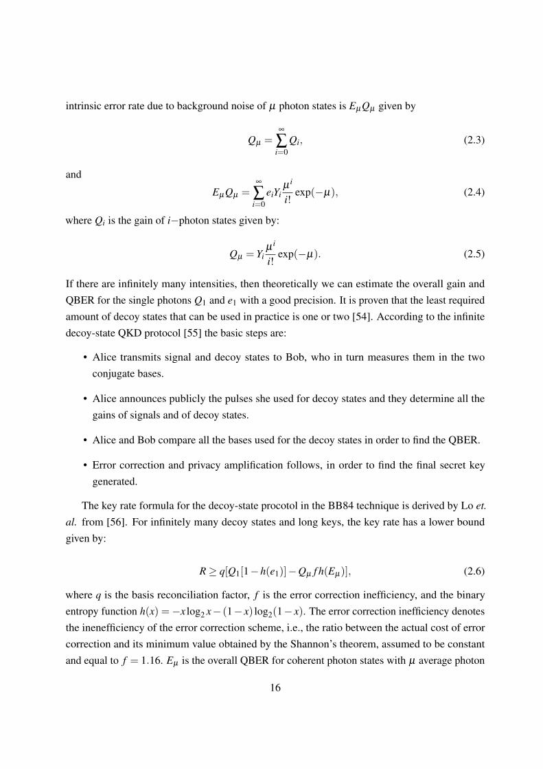
intrinsic error rate due to background noise of µ photon states is EµQµ given by
Qµ =∞
∑i=0
Qi, (2.3)
and
EµQµ =∞
∑i=0
eiYiµ i
i!exp(−µ), (2.4)
where Qi is the gain of i−photon states given by:
Qµ = Yiµ i
i!exp(−µ). (2.5)
If there are infinitely many intensities, then theoretically we can estimate the overall gain andQBER for the single photons Q1 and e1 with a good precision. It is proven that the least requiredamount of decoy states that can be used in practice is one or two [54]. According to the infinitedecoy-state QKD protocol [55] the basic steps are:
• Alice transmits signal and decoy states to Bob, who in turn measures them in the twoconjugate bases.
• Alice announces publicly the pulses she used for decoy states and they determine all thegains of signals and of decoy states.
• Alice and Bob compare all the bases used for the decoy states in order to find the QBER.
• Error correction and privacy amplification follows, in order to find the final secret keygenerated.
The key rate formula for the decoy-state procotol in the BB84 technique is derived by Lo et.
al. from [56]. For infinitely many decoy states and long keys, the key rate has a lower boundgiven by:
R≥ q[Q1[1−h(e1)]−Qµ f h(Eµ)], (2.6)
where q is the basis reconciliation factor, f is the error correction inefficiency, and the binaryentropy function h(x) =−x log2 x− (1− x) log2(1− x). The error correction inefficiency denotesthe inenefficiency of the error correction scheme, i.e., the ratio between the actual cost of errorcorrection and its minimum value obtained by the Shannon’s theorem, assumed to be constantand equal to f = 1.16. Eµ is the overall QBER for coherent photon states with µ average photon
16

number. In the case of the BB84 scheme the reconciliation factor equals to 1/2 due to the fact thathalf of the time Alice and Bob do not agree on the chosen basis. In Equation (2.6), we can assumeq = 1 if the efficient [57] QKD scheme is used. The key rate formula of Equation (2.6) with q = 1will be further used in Chapter 4. In the following subsection (2.4) I give a brief mathematicalanalysis for the key generation rate of the BB84 protocol.
2.4 BB84 Key Rate analysis
In this section we summarize the secret key generation rate for the efficient BB84 protocol[57] shown in Figure (2.2). In Figure (2.2), Alice is the transmitter sending pulses in eitherthe rectilinear or diagonal basis and Bob is the receiver, which decodes the message. Theycommunicate through an optical channel of distance L.
BB84QM QM
BB84BSMBSM BSM
BB84Encoder QM QM
BB84EncoderBSM
LBLAAlice Bob
BSM BSM
QM: Quantum MemoryBSM: Bell-state Measurement
BB84 BB84BB84Encoder
LAlice
BB84Meas.
Bob
Figure 2.2: The setup for the BB84 protocol.
With a clock rate of RS, the secret key generation rate is lower bounded by
RBB84 = RSY1[1−h(e1)− f h(e1)], (2.7)
in the single-photon case, and
RBB84 = RS[Q1(1−h(e1))− f Qµh(Eµ)], (2.8)
in the (infinitely many) decoy-state case, where µ is the average number of photons for thesignal state, which is dominantly used. In Equation (2.7), Y1 is the yield of single photons, or theprobability that Bob gets a click on his measurement devices assuming that Alice has sent exactlyone photon, including the dark counts and is given by
Y1 = YC +YE = 1− (1−η)(1− pdc)2, (2.9)
where η = ηch(L)ηd , with nch(L) = exp(−L/Latt) being the loss or a channel with attenuationlength Latt, ηd being the detector efficiency, and pdc is the dark count rate per pulse. In Equa-
17

tion (2.9)
YC = (1− pdc/2)(η +(1−η)pdc) and YE = pdc[(1−η)(1− pdc/2)+η/2] (2.10)
correspond, respectively, to the terms that, in the absence of misalignment, result in identical(Correct) versus non-identical (Error) bits shared by Alice and Bob. The QBER for the singlephoton case, e1, is the same for both bases and is given by
e1 =YE
Y1(2.11)
and the overall intrinsic error rate is given by
e1Y1 = edYC +(1− ed)YE = e0Y1− (e0− ed)(YC−YE)
= e0Y1− (e0− ed)η(1− pdc), (2.12)
where e0 = 1/2 and ed is the total misalignment probability for the channel.
Similarly, in Equation (2.8),
Q1 = Y1µe−µ ,
Qµ = QC +QE = 1− e−ηµ(1− pdc)2,
QC = (1− pdc/2)(1− e−ηµ + e−ηµ pdc),
QE = pdc[e−ηµ(1− pdc/2)+(1− e−ηµ)/2], (2.13)
are the corresponding gain terms [56] for the overall gain of single photon states Q1, of all pulseswith intensity µ Qµ , and the overall error probability QE . The overall intrinsic error rate is givenby
EµQµ = e0Qµ − (e0− ed)(1− e−ηµ)(1− pdc), (2.14)
e0 = 1/2,
and the overall QBER Eµ is given by
Eµ =QE
Qµ
. (2.15)
The decoy-state technique can be used when the signals are driven by the users. In the
18

following section, a different approach to exchanging secret keys is proposed, where the decoy-state method cannot be applied. Despite this, the next approach has an equal importance as theBB84 for the QKD.
2.5 Ekert protocol
An alternative approach to BB84 was introduced by Ekert in 1991, using entangled photon pairs[3]. This protocol relies on three properties of quantum entanglement. First is the fact thatentangled states are perfectly correlated, second is the quantum non-locality and the last is thedetection of eavesdroppers, whose attempts destroy these correlations.
Unlike the BB84, Alice and Bob in the Ekert protocol are now both receivers, connected to acentral source that creates entangled photons sending one to Alice and one to Bob. The sourcecould be untrusted (Eve could handle it) but the protocol is set in a way that the source emits pairsof polarisation singlet states [58] as
|φ〉= 1√2(| ↑↓〉− | ↓↑〉). (2.16)
Next Alice and Bob choose one out of the three coplanar axes for a polarization measurement.Alice’s and Bob’s orientation analyzers represent a basis and are given accordingly by:
φA = 0◦,45◦,90◦ (2.17)
andφB = 45◦,90◦,135◦. (2.18)
If their bases match then their results will be anti-correlated. For instance if Alice measuresvertical polarization then Bob will measure horizontal polarization and vice versa. If they choosedifferent bases, then the results will be random.
Public discussion follows to exchange the bases that Bob and Alice chose. They discardthe random results in order to establish the sifted key. For the results that match to prove theirentanglement they must violate the Bell inequality [23]. One key feature of this protocol is itsimmunity against source attacks. If Eve tries to manipulate the source to her own advantage, sheintroduces errors, detectable by Alice and Bob, whose data will now be uncorrelated. In such acase Alice and Bob acknowledge Eve’s presence and abort the protocol.
Many protocols succeeded the Ekert protocol relying on the security that entangled statesprovide. An example of these protocols is the BBM92 [22] that was proposed by Bennett, Brassard
19

and Mermin and it is an entanglement-based form of the BB84 protocol. More proposed protocolsthat share the same idea was the time-reversed EPR protocol [32, 33] and the device-independentone [59]. The modified BB84 with entangled photons has been experiementally constructed [60].
The main drawbacks that both prepare-and-measure protocols and entanglement-based proto-cols face are the multiple attacks that can be performed on the measurement devices [61]. Theseattacks significantly reduce the security of the protocol itself. As an alternative to prepare-and-measure and entanglement-based protocols, measurement-device-independent (MDI-QKD) wasproposed by Lo, Curty and Qi [4]. In the proposed protocol the measurement devices could be inthe hands of untrusted parties. It relies on entanglement swapping and the time-reverse EPR [33]protocol. The decoy-state protocol can also be used giving it another benefit. In the next section,the key features of this protocol are described.
2.6 MDI-QKD protocol
In MDI-QKD [4] a reverse EPR-based QKD security proof [33] is combined with the BB84source states to remove all the side-channel attacks in detectors automatically. Additionally in thecurrent protocol, the decoy-state technique, which was described in Section 2.3, can be applied,using weak coherent pulses (WCPs) that are generated by a laser, as a source. The main ideais that Alice and Bob would effectively share entangled states in their own laboratory using theteleportation trick.
Figure 2.3 shows the setup. Alice and Bob prepare photons in one of the four possible BB84polarisation states and in the measurement site a Bell state measurement is performed. Themeasurement device consists of linear optical elements as seen in Figure 2.3 with a 50−50 beamsplitter (BS), which on each end has a polarising beam splitter (PBS), and on each of the PBSoutput arms there is a single-photon detector. The measurement device is on the hands of anuntrusted party called Eve. Eve announces which detectors click. The procedure is repeatedseveral times by Alice and Bob. After the bases that were chosen are publicly announced througha public channel, Alice and Bob compare their results and discard the ones that their bases do notmatch and use the rest for key generation after error correction and privacy amplification. Thesecurity of the MDI-QKD relies on the time-reverse EPR protocol, therefore the measurementdevice module does not need to be trusted.
MDI-QKD offers several advantages over other QKD schemes. It removes all the side-channelattacks in detectors automatically since all the measurements can be done by Eve [33]. This is abenefit over the standard BB84 [1] and Ekert [3] protocols, where either Alice or Bob, or both
20

Figure 2.3: The MDI-QKD set up [4]The main idea is that Alice and Bob send either single photons or phase-randomized weakcoherent pulses in one of the four possible BB84 polarisation states [1] and send them to an
untrusted relay (Eve) placed in the middle. This relay setup performs partial BSM. On each endof the 50−50 beam splitter (BS), there are two polarising beam splitters (PBS) that on each armhave a single-photon detector. A successful BSM associates with two clicks and identifies two of
the four Bell states.
parties must perform some measurements. The transmission distance in MDI-QKD could reachalmost double the distance used in conventional BB84 setups. Also the key generation rate is asgood as the ones that use entangled photon pairs. Additionally MDI-QKD does not require a nearunity detection efficiency, but, using post-selection, unsuccessful BSMs can be removed withoutcompromising the security. To summarise, MDI-QKD is attractive for practical implementationand fully effective against any side channel attacks on detectors. An analysis of the key rate ofMDI-QKD follows next.
21

BB84 Encoder BSM
LBLAAlice Bob
BB84 Encoder
Figure 2.4: The MDI-QKD using two single-photon source encoders.
2.6.1 MDI-QKD key rate analysis
The secret key generation rate for the MDI-QKD scheme of Figure 2.4 is lower bounded by [48]
RMDI−QKD = RSY11[1−h(e11;X)− f h(e11;Z)], (2.19)
in the single-photon case, where Y11 is the conditional probability of successful middle BSMconditioned that Alice and Bob have sent exactly a single photon at the beginning using the samebasis, RS is the single photon repetition rate. The QBER in X and Z basis are given by e11;X ande11;Z when Alice and Bob use exactly single photons.
RMDI−QKD = RS[Q11(1−h(e11;X))− f Qµν ;Zh(Eµν ;Z)], (2.20)
in the decoy-state case, where µ (ν) is the average number of photons for signal states sent byAlice (Bob). The QBER in the Z basis becomes Eµν ;Z when using µ (ν) as the average numberof photons for signal states instead of single photons. Here, Q11 is the overall probability of asuccessful BSM if Alice and Bob, respectively, send pulses with µ and ν average number ofphotons and is given by
Q11(ηa,ηb) = µνe−µ−νY11(ηa,ηb) (2.21)
where ηa = ηch(LA)ηd and ηb = ηch(LB)ηd are transmission coefficients of each leg with lengths,LA and LB, respectively in Figure 2.4, and [48]
Y11(ηa,ηb) = (1− pdc)2 [ηaηb
2 +(2ηa +2ηb−3ηaηb)pdc +4(1−ηa)(1−ηb)p2dc],
e11;X(ηa,ηb,ed)Y11(ηa,ηb) = e0Y11(ηa,ηb)− (e0− ed)(1− pdc)2ηaηb/2,
e11;Z(ηa,ηb,ed)Y11(ηa,ηb) = e0Y11(ηa,ηb)− (e0− ed)(1− pdc)2(1−2pdc)ηaηb/2
(2.22)
22

with ed being the total misalignment probability. In the scheme of Figure 2.4, ed = edA(1−edB)+
edB(1− edA), where edA(edB) is the misalignment parameter for Alice (Bob) channel.
Similarly, using the results obtained in [48], we have
Qµν ;Z = Q′C +Q′EEµν ;ZQµν ;Z = edQ′C +(1− ed)Q′E , (2.23)
where
Q′C = 2(1− pdc)2e−µ ′/2
[1− (1− pdc)e−ηaµa/2
][1− (1− pdc)e−ηbµb/2
]Q′E = 2pdc(1− pdc)
2e−µ ′/2[I0(2x)− (1− pdc)e−µ ′/2]. (2.24)
In the above Equations, I0(x) is the modified Bessel function of the first kind and
x =√
ηaµηbν/2, (2.25)
y = (1− pdc)e−14 (ηaµ+ηbν), (2.26)
µ′ = ηaµ +ηbν . (2.27)
2.7 Memory-assisted MDI-QKD
In this thesis, we extend the idea of an MDI-QKD protocol, to achieve longer distances, with theuse of QMs. QMs can be located next to the BSM module in order to reduce the effect of channelloss on the key rate. The key advantage of our proposed memory-assisted MDI-QKD as comparedto the original MDI-QKD, is its higher resilience to channel loss and dark count.
In our protocol, Alice and Bob, at a rate RS, send BB84 encoded pulses to the middle station(dashed box in Figure (2.5)). At the QMs, for each incoming pulse, we either apply a loadingprocess by which we can store the state of the photons into memories and verify it, or use theindirectly heralding scheme of Figure (2.5(b)). Once successful for a particular QM, we stop theloading procedure on that QM, and wait until both memories are loaded, at which point, a BSM isperformed on the QMs. The BSM results are sent back to Alice and Bob, and the above procedureis being repeated until a sufficient number of raw key bits is obtained. The rest of the protocol isthe same as that of MDI-QKD. Sifting and postprocessing will be performed on the raw key to
23

BB84 Encoder QM QM
BB84 EncoderBSM
Retrieved photon(a)Loading process
A B
LBLAAlice Bob
(b)A B
BB84 Encoder QM QM
BB84 EncoderBSM
LBLAAlice Bob
BSM BSM
Entangled with QM
A B
g
BB84 Encoder
BB84 EncoderBSM
(c)
LBLAAlice Bob
Figure 2.5: (a) MDI-QKD with directly heralding quantum memories. Alice and Bobuse the efficient BB84 protocol to encode and send pulses to their respective QM inthe middle of the link. At each round, each QM attempts to store the incoming pulse.Once they are both loaded, we retrieve the QMs’ states and perform a BSM on theresulting photons. (b) MDI-QKD with indirectly heralding quantum memories. Ateach round, an entangling process is applied to each QM, which would generate aphoton entangled, in polarization, with the QM. These photons interfere at the BSMmodules next to the QMs with incoming pulses from the encoders. As soon as one ofthese BSMs succeeds, we stop the entangling process on the corresponding QM, andwait until both QMs are ready for the middle BSM operation. In this case, QMs arenot required to be heralding; a trigger event is declared by the success of the BSMlocated between the QM and the respective encoder. (c) The original MDI-QKDprotocol [4].
obtain a secret key. In this thesis, we neglect the finite-size-key effects in our analysis [62].
In the no-memory MDI-QKD case, the condition set for a successful BSM, is that both pulsesmust survive the path loss. Therefore, the key generation rate scales with the loss in the entirechannel. In our scheme, each pulse, still requires that it will survive the path loss over half ofthe link, but this can happen in different rounds for the signal sent by Alice as compared to thatof Bob. We essentially achieve the quantum repeater benefit in that the key generation rate, inthe symmetric case, scales with the loss over half of the total distance. Moreover, in the case ofdirectly heralding memories, our scheme is roughly immune against dark counts [47]. This isbecause the measurement efficiency in the BSM module is typically a few orders of magnitudehigher than that of dark count rates. Dark counts will then only sightly add to the error rate. In ourscheme, memory decoherence errors play a major role as we will explain in detail in Chapter 4.
Moreover, we study what are the writing times of these two different type of QMs. The writingtime is a crucial parameter that defines the performance of the key rate versus distance. More
24

specifically, writing time, in the directly heralding QMs, denotes the time difference between thetime that a pulse arrives at the QM and the time that a successful/unsuccessful loading is denoted.The writing time for the indirectly heralding QMs, denotes the difference between the entanglingprocess and BSM operation.
Another important parameter we take into consideration is the QM’s coherence or dephasingtime (T2). This parameter directly affects the key rate versus distance as well.
As we explain in detail in Chapter 4, for high values of coherence times and short writingtimes, we prove that a memory-assisted system with suitable QM candidates, can outperform, interms of key rate conventional no-memory QKD systems.
2.8 The main contributions of this thesis
In Chapter 1, we introduced the key features of QKD and the challenges it deals for a realisticimplementation. In this thesis, we work on the following challenges to find possible solutions thatcan improve the performance of the system. These problems and our proposed solutions are givenbelow:
Problem: QKD offers unconditional security based on the laws of quantum physics, howeverthe practical implementation of specific QKD systems is prone from possible attacks that can beperformed on the measurement parts of the system, if controlled by the users. MDI-QKD offersan alternative solution to overcome this limitation. Therefore the modeling of such a system hasto be studied in full to check:
1. how it performs in a practical scenario, when, for instance, sources are imperfect in thesense that there are errors in the state-preparation stage; and
2. how can quantum memories improve the performance of an MDI-QKD system regardingits distance and rate and what requirements they must fullfil in order to achieve the highestpossible performance.
Our contribution: In Chapter 3, we analyse a typical MDI-QKD system that uses single-photon sources but with potential modulation errors. We give a detailed description of how thekey rate is affected by these errors, which allows us to identify the regimes of operation. We willshow that MDI-QKD can still perform efficienctly under certain assumptions on the fidelity ofeach single-photon state.
Our contribution: In Chapter 4, we fully analyse an MDI-QKD system with imperfect QMs,where we analytically compute the secret key rate. QMs are of great importance when it comes
25

to reach longer distances as it proven by the results. We find regimes of operation where ourproposed system performs better than conventional QKD systems. The results are promising fornear-future practical implementations.
Problem: The memory-assisted MDI-QKD needs to relax the constraints on the QMs to enablethe use of a larger number of the avalaible QMs.
Our contribution: In Chapter 5 an alternative approach to the memory-assissted MDI-QKDis to use QMs that are indirectly heralding. We combine the memory-assisted MDI-QKD setupwith entangled photon-pair sources. As we consider a realistic scenario we combine the idea ofEPR sources being imperfect by including modulation errors. A full analysis to retrieve the key isprovided and a comparison to the previous case is made. We show that this system allows us tostill have a fully functional and efficienct system under certain assumptions.
26

Chapter 3
MDI-QKD with imperfect encoders
3.1 Introduction
In this chapter we focus on the state-preparation (modulation) flaws in the single-photon sourcesin an MDI-QKD setup. In the key rate analysis presented in Chapter 2, it was assumed that eachsource will generate the exact BB84 states as required. In a practical setup, this may not be arealistic assumption for the source. The key objective is to establish an employable MDI-QKDprotocol that remains secure under the assumption of both imperfect single-photon sources andimperfect measurement devices. The main goal in this chapter is to calculate the key generationrate versus distance for single-photon sources with state-preparation imperfections. During thepreparation of this thesis, a similar work has been reported by Lo et al. [63]. The work presentedhere has been obtained independently, and goes beyond the results presented in [63].
An ideal BB84 encoder has two properties. The first is that the source emits ideal singlephotons and the second is that the information is encoded without errors. However, these twoassumptions can hardly be fulfilled with the current technology. Even single-photon sources thatgenerate exactly one photon may produce a different polarisation from the initially intended stateduring the encoding process. This type of error is referred to as modulation errors. To address thisissue, in this chapter, we consider imperfect encoders, as shown in Figure 3.1. The main objectiveis to analyse how the performance of this practical scenario would be affected when modulationerrors are accounted for. We point out that this analysis is a preliminary step for Chapter 5, where
27

imperfect EPR sources are used in a memory-assisted MDI-QKD.
Imperfect BB84
EncoderBSM
LBLAAlice Bob
Imperfect BB84
Encoder
Figure 3.1: Asymmetric setup with imperfect BB84 encoders in an MDI-QKD scheme.
3.2 This chapter’s contribution
• We analyse the MDI QKD system when the sources of each user are prone to modulationerrors at the state-preparation stage. We fully analyse how to obtain the key rate and QBERformulas in this scenario.
• We consider different initial states of the single-photon source for each user. Firstly weassume that both users have imperfect single-photon sources that have a mixture of twosingle-photon states in a symmetric setup, where both users are at equal distance from themiddle measurement module. We compare the key rate and QBER against the ideal case.
• In the second case, we consider that only one user has an imperfect single-photon source,whereas the other one has an ideal one. The reason is that we will be using an analogouscase in Chapter 5.
• Lastly, we compare the case where the single-photon states can tolerate more imperfectionsby including cross-terms in our initial density matrix.
This chapter is organised as follows. Section 3.3 analyses the MDI-QKD with imperfectsingle-photon sources. In Section 3.4, an analysis of the key rate is provided. In Section 3.5 theresults are summarised for different setups and fidelities and we conclude in Section 3.6.
3.3 System description
In this chapter, we assume that Alice and Bob are equipped with single-photon sources thatgenerate qubit states but not necessarily in the desired polarised BB84 state. Alice and Bob followthe same procedure as described in Section 2.6 for a typical MDI-QKD with the difference that the
28

single-photon sources are assumed imperfect (see Figure 3.1). The outcome of such an imperfectencoder, for user x = A,B, is modeled by the following density matrix:
ρ(m)x;K = α
(m)x;K |H〉〈H|+β
(m)x;K |H〉〈V |+β
(m)∗x;K |V 〉〈H|+ γ
(m)x;K |V 〉〈V |, (3.1)
where m = {0,1} represents the transmitted bit in basis K = {X ,Z}. |H〉 and |V 〉 are two of thefour BB84 polarised states in horizontal and vertical polarizations. α
(m)x;K , β
(m)x;K , β
(m)∗x;K and γ
(m)x;K are
the probabilities respectively for the BB84 polarised states respectively |H〉〈H|, |H〉〈V |, |V 〉〈H|and |V 〉〈V |. According to the normalization fo the density matrix the diagonal elements mustobey the following condition α
(m)x;K + γ
(m)x;K = 1. We use the same notation as in Chapter 2 for other
system parameters. In particular, the distance between Alice (Bob) and the measurement moduleis denoted by LA (LB). The total distance between Alice and Bob is denoted by L = LA +LB. Thetransmission coefficient for a channel with length l is given by
ηch(l)≡ exp(−l/Latt), (3.2)
where Latt is the attenuation length of the channel (roughly, 22 km for 0.2 dB/km of loss).
Next we obtain the secret key generation rate for the scheme of Figure 3.1, when input statesare given by Equation (3.1). Suppose Alice is sending bit m and Bob is sending bit n, in basis K.Their joint input state is then given by
ρ(mn)AB;K = ρ
(m)A;K⊗ρ
(n)B;K. (3.3)
In the following we model what happens to the initial state ρ(m)A;K and ρ
(n)B;K once the corre-
sponding photons travel through the setup of Figure 3.2. We model the path loss and detectorefficiencies by beams splitters (BSs), as showing in Figure 3.2, the transmission coefficientsηch(LA), ηch(LB), and ηd . Their combined effect can then be represented by two beam splitterswith transmission coefficients ηα = ηch(LA)ηd , for Alice’s side, and ηβ = ηch(LB)ηd , for Bob’sleg. If we represent the quantum operator by a beam splitter with transmissivity η by Bη , thejoing state right before the 50−50 BS is given by
ρ(mn)′
AB;K = trV (BηαBηβ
(ρ(mn)AB;K)B
†ηβ
B†ηα), (3.4)
29

ηch(LA)
50-50 BS
DH2DV2DV1
nd
DH1
ηch(LB)
PBS ηα ηβ≡
(a)(b)
ndPBS
Figure 3.2: Modeling of the channel loss and detection efficiency in the BSM module.
whereBη |P〉|0〉=
√n|P〉〈0|+
√1−n|0〉〈P|, (3.5)
and P = {H,V} denotes a photon in one of the polarised BB84 states and tracing is done over allvacuum modes entering the BSs in Figure 3.2(b).
BB84QM QM
BB84BSM
BB84Encoder QM QM
BB84EncoderBSM
LBLAAlice Bob
QM: Quantum MemoryQM: Quantum MemoryBSM: Bell-state Measurement
DH1 DH2DV2DV1
50-50
PBS PBS
BS: Beam splitter
BSM50-50
BS
BS: Beam splitterPBS: Polarizing BS
Figure 3.3: Bell-state measurement module for polarization states.
Next in order to model the BSM operation (see Figure 3.3), we apply the butterfly operatorBBF that includes the operation of both the BS and Polarising BS (PBS) (see Appendix C). Withthe help of MATLAB, we apply the butterfly operator BBF on ρ
(mn)′
AB;K . The density matrix right
before photodetection, ρ(out)AB , in Figure 3.3, is then given by
ρ(out)AB = BBF(ρ
(mn)′
AB;K )B†BF . (3.6)
30

Having calculated the output state, an analysis of the key rate will follow in the next section.
3.4 Key rate analysis
In this section we obtain the parameters needed to calculate the key rate in the case of imperfectsingle-photon sources. We start with the output state in Equation (3.6). One needs to apply themeasurement operators MDiD j to find all possibilities of a successful BSM. More specifically, theprobability that detectors i and j, where i, j = H1,V1,H2,V2 in Figure 3.3 click is given by
PDiD j(ρ(m)A;K⊗ρ
(n)B;K) = tr(ρ(out)
AB MDiD j), (3.7)
where measurement operators are defined by
MDiD j = (1− pdc)2[Ii− (1− pdc)|0〉ii〈0|] (3.8)
⊗[I j− (1− pdc)|0〉 j j〈0|]
⊗|0〉kk〈0|
⊗|0〉ll〈0|,
where i, j are the corresponding detectors that click, whereas k, l are the single-photon detectorsin Figure 3.3, that do not click, I is the identity operator and pdc is the dark count probability.The probability that an acceptable click pattern occurs in the K basis, similar to Section 2.6.1 isdefined as
QKAB = QK
C +QKE , K = X ,Z, (3.9)
whereQK
AB =14 ∑
m=0,1QAB(ρ
(m)A;K⊗ρ
(n)B;K), (3.10)
and more analytically is given by
QKAB(ρ
(m)A;K⊗ρ
(n)B;K) = PDH1V1
(ρ(m)A;K⊗ρ
(n)B;K)+PDH1V2
(ρ(m)A;K⊗ρ
(n)B;K)
+PDV1H2(ρ
(m)A;K⊗ρ
(n)B;K)+PDH2V2
(ρ(m)A;K⊗ρ
(n)B;K). (3.11)
The error terms in Z basis, QZE , corresponds to when Alice and Bob send the same bit, and it
31

is given by
QZE =
12 ∑
m=0,1QZ
AB(ρ(m)A;K⊗ρ
(m)B;K), (3.12)
where QZAB defined by Equation (3.11) and represents the probability of a successful BSM if Alice
and Bob send a state given in the argument. The QBER in the Z basis is then given by
e11;Z =QZ
EQZ
AB. (3.13)
The error probability in the X basis can be calculated by considering two cases. If the two sendidentical its, we have errors if we get two clicks on two orthogonally polarised detectors from twoopposite sides, i.e., DH1V2 or DV1H2 (see Figure 3.2):
QXE1 =
12 ∑
m=0,1[PDH1V2
(ρ(m)A;X ⊗ρ
(m)B;X )+PDV1H2
(ρ(m)A;X ⊗ρ
(m)B;X )] (3.14)
If the bits sent from the users are complimentary then an error is occured in the case that twodetectors click on the same side, i.e., DH1V1 or DH2V2 (see Figure 3.2). Then the error probabilityin the X basis becomes
QXE2 =
12 ∑
m=0,1[PDH1V1
(ρ(m)A;X ⊗ρ
(1−m)B;X )+PDH2V2
(ρ(m)A;X ⊗ρ
(1−m)B;X )] (3.15)
The QBER in the X basis is then given by
e11;X =QX
EQX
AB, (3.16)
where QXE = QX
E1 +QXE2.
Finally to find the key rate we have to take into account the probability of a successful clickpattern in the Z basis as given from Equation (3.11) when the input state is given by Equation(3.1), given that the users have sent a single-photon each. Then the key rate is given by [64]
R≥ QZAB[1−h(e11;X)− f h(e11;Z)]. (3.17)
Having fully analysed the key rate formula and the QBER we move on to the next section toapply numerical results in specific cases, such as the symmetric setup when the source fidelitieschange in a given input density matrix.
32

3.5 Numerical results
In this section, we study the impact of different parameters on the secret key generation rate ofour scheme in different cases. We compare in a symmetric setup the QBER in X and Z basesand additionally the secret key generation rate per transmitted pulse for different fidelities of thesingle-photon BB84 states. We continue with the case of an imperfect single-photon source onone side and an ideal single-photon source on the other side to obtain again the QBER in X and Z
bases and the key rate for both the asymmetric and symmetric setups. In the asymmetric setupwe make the assumption that Alice is at distance LA = L from the measurement module, whereasBob is at zero distance from the measurement module, i.e., LB = 0. We have used Matlab toanalytically obtain expressions for Equations (3.12), (3.16) and (3.17). In the symmetric setupthe distance for Alice and Bob is considered equal, i.e., LA = LB = L/2. Finally, we compare theresults of the two setups. Next we compare the symmetric and asymmetric setups again in termsof the secret key rate and QBER versus distance. All results have been obtained assuming an errorcorrection inefficiency f = 1.16, 0.2 dB per km of loss in the channel, detection efficiency ofηd = 0.15, dark count rate per pulse pdc = 3×10⁻⁶, and no misalignments, i.e., edA = edB = 0.We used the density matrix from Equation (3.1) where Alice and Bob use the BB84 encodedsingle photon states in either X or Z basis and we analyse how these parameters change underdifferent assumptions on the fidelity of the input density state. The fidelity is a parameter thatestimates the quality of a state. In this case we are studying the quality of the single-photon statesand their imperfections in two scenarios, when the users both use an imperfect single-photonsource and when one user uses an imperfect single-photon source and the other uses a perfectsingle-photon source.
• Case A
In the case that both users use imperfect single-photon sources, then the input density matrixstands as Equation (3.1). We want to compare the QBER terms in X and Z basis, fordifferent fidelities of the diagonal terms. Hence we take the non-diagonal terms equal tozero (β ,β ∗ = 0) from Eq. (3.1). The input state for Alice and
ρ(m)A;K = α
(m)A;K|H〉〈H|+ γ
(m)A;K|V 〉〈V | (3.18)
and similarly for Bobρ(n)B;K = α
(n)B;K|H〉〈H|+ γ
(n)B;K)|V 〉〈V | (3.19)
where α+γ = 1 and m,n= {0,1} represents the transmitted bit in basis K = {X ,Z}. Alice’s
33

input state for bit zero is given by
ρ(0)(A;Z) = F |H〉〈H|+(1−F)|V 〉〈V |, (3.20)
and for bit one,ρ(1)(A;Z) = F |V 〉〈V |+(1−F)|H〉〈H|, (3.21)
where F is the fidelity of the single-photon state with given input in the Z basis. Bob’s inputstates are similar to Equations (3.20) and (3.21). Neglecting all other sources of error butthe modulation errors, the QBER in Z becomes
--- F=100% --- F=99% --- F=98% --- F=97%--- F=95%
Figure 3.4: This is a comparison of the QBER-versus-distance in the Z and X basis ofa symmetric setup for different fidelity values.
e11;Z =2F(1−F)
2F(1−F)+F2 +(1−F)2
= 2F(1−F). (3.22)
To derive the QBER in Z basis, we have considered the cases that we have both users sendidentical bits but due to the imperfections of single photons described by Equations (3.20)and (3.21) there is a probability to have a click on two detectors as expected in the correct
34

case. For instance, if Alice and Bob send bit zero, then there is a probability QZE = 2F(1−F)
to get a correct pattern of clicks. We use a similar single-photon state with fidelity F to theintended state for Alice or Bob in the X basis. For instance for bit zero, we have
ρ(0)(A;X)
= F |+〉〈+|+(1−F)|−〉〈−|
=12(|H〉〈H|+ |V 〉〈V |)+
(2F−1)2
(|H〉〈V |+ |V 〉〈H|) (3.23)
Under these assumptions, the QBER in X is equal to the Z basis. Figure 3.4 shows theQBER versus distance for different values of fidelity in the scenario of a symmetric setup.It can be seen that as the fidelity is lower the QBER is increased due to the inefficienciesfrom the source’s part. If the fidelity remains higher than F = 95% then the protocol is stillsecure and practically employable. For values roughly lower than F = 95% the protocol isinsecure. At low distances, the major source of error is the modulation error so the QBERfollows the relation in Equation (3.21). The QBER becomes very high for distances ofroughly 300 km because the dark count effects becomes the major source of errors in longdistances. The QBER in X basis is similar to the QBER in Z.
• Case B
In the case that Alice uses an imperfect single-photon source and Bob uses instead an idealsingle-photon source, then the input density matrix for Bob according to Equation (3.1)will become the same as Equation (3.19) with the difference that either α or γ becomes0 and the other one becomes 1. For Alice the input state is given by Equations (3.20) and(3.21). The QBER in Z, in the low distance regime is then given by
e11;Z =2(1−F)
2F +2(1−F)= 1−F. (3.24)
The QBER in X is equal to the one from Z basis for the above input setting. The resultsfor the QBER in Z are given in Figure 3.5. From Figure 3.5, we can see that as the fidelitydecreases the state-preparation flaws contribute to higher values of QBER when comparedto the corresponding values of QBER in Z basis for the same distance. This is similar to theQBER in Figure 3.4 with the difference that in the former, the values of QBER is almost
35

half the value than the latter. This is due to the fact that the QBER in the case where bothusers have imperfect single-photon sources there is a higher chance for a modulation errorat the sources’ side, whereas if only one user uses an imperfect source and the other has aperfect single-photon source, the chance is lower.
--- F=100% --- F=97%--- F=95%--- F=92%
Figure 3.5: Comparison of the QBER in Z basis for a symmetric setup for differentfidelity values using an imperfect single-photon source and an ideal single-photonsource.
• Case C
Here, we study the effect of the non-diagonal terms, in the input density matrix Equation(3.1) (β ,β ∗> 0). We have made the assumption, for simplicity, that only the X basis acceptsnon-ideal single photons, whereas the Z basis accepts only perfect single photon states. Themotivation behind this assumption is to study how it would affect the performance of thekey generation rate if one of the single-photon encoders tolerates modulation errors and theother one is considered an ideal single-photon encoder. We use this assumption in Chapter5.
The input density matrix for each user is given similarly to Equation (3.23) with thedifference that the fidelity includes also the non-diagonal terms. Figure 3.6 shows how theQBER in X basis changes versus distance for different values of the non-diagonal terms in
36

a symmetric setup. In this scenario we kept the values for Z the same and equal to the idealsingle photon scenario. As we can see from this figure the lower the fidelity, the higher theQBER is at the sources’ side. Similarly for longer distances than roughly 300 km the darkcount effect becomes dominant over the correct clicks leading to non secure keys beinggenerated. The fidelity is proportionally related to the non-diagonal terms therefore forhigher values of fidelity the higher the values of the non-diagonal terms will be. Given theQBER in Z basis is very small, the QBER in X can be more than 11%.
--- F=100% --- F=97% --- F=95% --- F=92% --- F=90%
Figure 3.6: This is a comparison of the QBER-versus-distance in the X basis of asymmetric setup for different fidelity values of the non-diagonal terms.
In the next section we will compare in the above three cases how the key rate versus distanceperformance is affected in each scenario.
3.5.1 Rate-versus-distance
In this sections, we discuss the effects of fidelity and symmetry of the setup on the secret keygeneration rate. We make a comparison for the symmetric (LA = LB = L/2) and asymmetric(LA = L and LB = 0) setup cases respectively to the cases taken in the previous section.
• Case A
37

In this scenario both Alice and Bob use imperfect single photon states (Equation (3.18) and(3.19) where the non-diagonal terms are taken as zero). In Figure 3.7, we can see that, for asymmetric setup, as the fidelity of the single photon states decreases the secure distancebecomes lower. Secure distance is defined as the distance where the QBER is lower than11%. The fidelity of a single photon source affects directly the QBER in both bases andtherefore the key rate in terms of distance. For values of fidelity equal and lower than 95%there is a significant drop on the distance, reaching roughly 150 km. If the fidelities are kepthigher than 97%, the distance ranges from around 280 km to the highest given by 320 km(for F=100%). The cut-off distance in each case is due to the path loss and dark count beingdominant over the correct clicks, therefore there is a lower chance to retrieve a secret key.
--- F=100%--- F=98%--- F=97% --- F=95%
Figure 3.7: Comparison of the Rate-versus-distance for a symmetric setup for differentfidelity values.
• Case B
In this case Alice and Bob follow the input states given from Case B in the previous sectionwhere Alice sends perfect single photon states whereas Bob sends imperfect single photonstates. The Figure 3.8 is for the symmetric setup for different values of fidelity. As in theprevious case in Figure 3.7 as the fidelity of the single photon states decreases, the securedistance decreases accordingly. A difference between these two Figures is that the errors
38

contributed in the former case are from both sources being imperfect whereas in the lattercase there is only one imperfect source. This means that for the same fidelities (e.g. 95%)the distance reaches longer lengths in the latter case (over 250 km) whereas in the formercase it reaches up to roughly 160 km.
--- F=100%--- F=97% --- F=95%--- F=91%
Figure 3.8: Comparison of the key rate versus distance for a symmetric setup fordifferent fidelity values using an imperfect single-photon source and an ideal single-photon source.
In the same scenario where the input states are given as above, we have also made acomparison between an asymmetric and a symmetric setup. Figure 3.9 shows the differencebetween a symmetric and an asymmetric setup for the same fidelity values. The differencebetween the symmetric and asymmetric for fidelities 97% and 98% is that the asymmetrichas lower key rate for the same distances and also reaches shorter distances (150 km and170 km respectively) compared to the symmetric counterparts (close to 300 km and 350kmrespectively).
The difference between the asymmetric and symmetric case is the proximity of the BSMmodule to the source. The overall scaling of the path loss remains the same for both setups.However in the asymmetric, one of the sources is next to the BSM module, thus the error isgiven only by one side. This has a negative effect on the asymmetric case giving a higher
39

QBER and at the same time, lower key rate for the same distances and fidelities as we cansee from Figure 3.9.
Symmetric:-- F =98%--- F=97% Asymmetric:--- F=98% --- F=97%
Figure 3.9: Comparison of the key rate versus distance for a symmetric and anasymmetric setup for different fidelity values using an imperfect single-photon sourceand an ideal single-photon source.
• Case C
In this case the input states are given as in Section 3.5 where for both Alice and Bob in theZ basis use ideal BB84 encoded single photons, whereas in the X basis their single photonshave imperfections during the state-preparation stage. From Figure 3.10 As the fidelity inthe X basis decreases, the key rate decreases. The higher the fidelity, the higher the key rateand the longer the secure distance is. For example at F = 97% the distance reaches up to300 km whereas for fidelities of 85% the cut-off distance is limited to 240 km. Because inthis case, we have mainly X errors we can tolerate rather low fidelities.
3.6 Conclusion
In this Chapter, we studied and analysed the scenario of imperfect single-photon sources in anMDI-QKD protocol in terms of secret key generation rate and QBER with two different types of
40

--- F=100% --- F=97% --- F=93% --- F=89%--- F=85%
Figure 3.10: Key rate versus distance for different fidelities of the non-diagonal termsin a symmetric setup.
sources and symmetries of the setup.We considered different sources of imperfections such aschannel loss, quantum efficiency and dark counts and obtained the optimal regime of operation as afunction of system parameters. We first modeled the density matrix for an imperfect single-photonsource in order to obtain the secret key rate and the QBER in X and Z bases.
Firstly we compared an imperfect single photon source, which emits a mixture of singlephotons of different polarisations at the state-preparation stage with different probabilities. Wemade a comparison for the diagonal terms and found that the higher fidelity they have the lowerthe QBER is and the higher key rate and longer distances can be achieved. If the fidelity is keptwell above 95% we can still retrieve secret key in distances longer than 150 km.
Additionally we compared how the key rate performance changes in the case when one of theusers has an ideal single-photon source and the other user has an imperfect single-photon sourcewith the case that both users have imperfect sources. For the same fidelities, we have found thatthe key rate is higher for longer distances in the former when compared to the latter case.
Finally for an ideal source and an imperfect source, we compared two different symmetrysetups for the same input density matrix as above. In the symmetric setup we assume that bothusers are at an equal distance from the measurement module. In the an asymmetric setup thedistance for one user is taken as zero and the other user is at a double the distance from the first
41

case. As their total loss remains equal for both cases, we compare how the symmetry changeswhen the BSM module is either next to one of the sources or located in the middle of both sources.We have concluded that in the asymmetric case, the QBER is higher as the loss is modeled on oneside instead of both as in the symmetric case. This works as a negative effect for the asymmetricsetup as the key rate is lower when compared to its counterpart in the symmetric setup for thesame distances.
In this chapter we showed that an MDI-QKD protocol is still employable when consideringthat the source has imperfections at the state-preparation stage. To achieve a more efficient andstill feasible implementation we introduce QMs in an MDI-QKD scenario in Chapters 4 and 5which under certain assumptions we can improve the performance of the MDI-QKD protocol.
42

Chapter 4
Memory-assisted MDI-QKD
4.1 Introduction
Despite all commercial and experimental achievements in QKD [38, 39, 40, 41, 42], reachingarbitrarily long distances is still a remote objective. The fundamental solution to this problem, i.e.,quantum repeaters, is known for over a decade. From early proposals by Briegel et al. [43] tothe latest no-memory version by Munro et al. [44], quantum repeaters, typically, rely on highlyefficient quantum gates comparable to what we may need for future quantum computers. Whilethe progress on that ground may take some time before such systems become functional, anotherapproach based on probabilistic gate operations was proposed by Duan and coworkers [45],which could offer a simpler way of implementing quantum repeaters for moderate distances ofup to around 1000 km. The latter systems require quantum memory modules with high couplingefficiencies to light and with coherence times exceeding the transmission delays, which are yet tobe achieved together. In this chapter, we propose a protocol that, although is not as scalable asquantum repeaters, for certain classes of memories, relaxes, to some extent, the harsh requirementson memories’ coherence times, thereby paving the way for the existing technologies to beat thehighest distance records achieved for no-memory QKD links [38]. The idea behind our protocolwas presented in [46], and, recently, and, independently, has also been used in [47]. This workproposes additional practical schemes and rigorously analyzes them under realistic conditions.
Our protocol relies on concepts from quantum repeaters, on the one hand, and the recently
43

proposed measurement-device-independent QKD (MDI-QKD), on the other. The original MDI-QKD [4] relies on sending encoded photons by the users to a middle site at which a Bell-statemeasurement (BSM) is performed. This BSM can be done by an untrusted party, e.g., the serviceprovider, which makes MDI-QKD resilient to detector attacks, e.g., time-shift, remapping, andblinding attacks [25, 26, 27, 28, 29, 30]. The security is then guaranteed by the reverse EPRprotocol [33]. In our scheme, by using two quantum memories at the middle site, we first store thestate of the transmitted photons in the memories, and perform the required BSM, only when bothmemories are loaded. This way, similar to quantum repeaters, we achieve a rate-versus-distanceimprovement as compared to the MDI-QKD schemes proposed in [4, 48], or other conventionalQKD systems that do not use quantum memories.
There is an important distinction between our protocol and a conventional quantum repeatersystem. In a typical quantum repeater link, which relies on initial entanglement distributionamong neighboring nodes, the repeat period for the protocol is mainly dictated by the transmissiondelay for the shortest segment of the repeater system [49, 50]. In our scheme, however, the repeatperiod is constrained by the writing time, including the time needed for the herald/verificationprocess, into memories. This implies that using sufficiently fast memories, one can run ourscheme at a faster rate than that of a quantum repeater, thereby achieving higher key generationrates, as compared to conventional QKD links, and at lower coherence times, as compared toprobabilistic repeater systems. This increase in clock rate is what our proposal shares with therecently proposed third generation of quantum repeaters, which use quantum error correctioncodes to compensate for loss and errors, thus also being able to speed up the clock rate to localprocessing times [44]. The need for long coherence times remains one of the key challenges inimplementing the first generations of quantum repeaters before the latest no-memory quantumrepeater proposals can be implemented.
The above two benefits would offer a midterm solution to the problem of long-distance QKD.While our scheme is not scalable the same way that quantum repeaters are, it possibly allows us touse the existing technology for quantum memories to improve the performance of QKD systems.In the absence of fully operational quantum repeater systems, our setup can fill the gap betweentheory and practice and will become one of the first applications of realistic quantum memories inquantum communications.
44

4.2 This chapter’s contibution
• We analyze the memory-assisted MDI-QKD in a realistic scenario. We consider twodifferent sources. Single-photon sources and the decoy states. In the first case, we use BB84single photon states and in the second, we use phase-randomized coherent states. In eachcase we find the secret key generation rate versus distance.
• We analyse the storage time of imperfect QMs and how it affects system performance.We show that these QMs have lower coherence time requirements compared to the multi-memory probabilistic quantum repeaters. Additionally we prove that our proposed protocolcan outperform the conventional QKD schemes in terms of rate-versus-distance and has theadvantage of being practically constructed with the means of existing technology for QMs.
• We also consider the case of imperfect ensemble based QMs in the memory-assisted MDI-QKD. The ensemble based QMs suffer from multiple excitations thus leading to a lowerperformance than conventional no-memory systems in practical regimes of interest.
The rest of the Chapter is structured as follows. In Section 4.3, we describe our proposedschemes and the modeling used for each component therein. Section 4.4.1 presents our key rateanalysis, followed by some numerical results in Section 4.5. Section 4.7 concludes the Chapter.
4.3 System description
Our scheme relies on “loading” quantum memories (QMs) with certain, unknown, states of light.This loading process needs to be heralding, that is, by the end of it, we should learn about itssuccess. Within our scheme, two types of memories can be employed, which we refer to bydirectly versus indirectly heralding QMs. Some QMs can operate in both ways, while someothers are more apt to one than the other. By directly heralding memories we refer to the classof memories to which we can directly transfer the state of a photon and we can verify—withoutrevealing or demolishing the quantum state—whether this writing process has been successful.An example of such memories is a trapped atom in an optical cavity [65]. In the case of indirectlyheralding memories, a direct writing-verification scheme may not exist. Instead, we assume thatwe can entangle a photonic state with the state of such QMs [45, 66, 67], and later, by doing ameasurement on the photon, we can effectively achieve a heralded writing into the memory. Thesetwo approaches of writing cover most relevant practical examples to our scheme.
45

The scheme for directly heralding memories works as follows [46, 47]; see Figure 2.5(a). Thetwo communicating parties, Alice and Bob, send BB84 encoded pulses [1], by either single-photonor weak laser sources, towards QM units located in the middle of the link. Each QM stores aphoton in a possibly probabilistic, but heralding, way. Once both memories are loaded, we retrievetheir states and perform a BSM on the corresponding photons. A successful BSM indicates someform of correlation between the transmitted bits by Alice and Bob.
We can easily extend the above idea to the case of indirectly heralding memories. An additionalBSM, on each side, along with an entangling process between photons and QMs, can replacethe verification process needed for directly heralding memories. In this case, see Figure 2.5(b), asuccessful BSM between the transmitted photon by the users and the one entangled with the QM,would effectively herald a successful loading process, that is, the state of the QM is correlatedwith the quantum state sent by the users.
Here, for simplicity, we work with polarization entanglement. Suppose once we entangle thememory A with a single photon P, the joint state of the two is given by
1√2[|sH〉A|H〉P + |sV 〉A|V 〉P], (4.1)
where |H〉P and |V 〉P, respectively, represent horizontally and vertically polarized single photons,and |sH〉A and |sV 〉A are the corresponding memory states. By tracing out the memory system A inEquation (4.1), one can see that the photonic state out of the memory is similar to that of a BB84encoder. Each leg of Figure 2.5(b), from the source to the respective QM, is then similar to anasymmetric setup of the original MDI-QKD scheme as depicted in Figure 2.5(c). The workingof the system in Figure 2.5(b) will then follow that of the original MDI-QKD. We will use thissimilarity in our analysis of the system in Figure 2.5(b).
The main advantage of our scheme as compared to the original MDI-QKD, in Figure 2.5(c), isits higher resilience to channel loss and dark count. In the no-memory MDI-QKD, both pulses,sent by Alice and Bob, should survive the path loss before a BSM can be performed. The keygeneration rate then scales with the loss in the entire channel. In our scheme, each pulse stillneeds to survive the path loss over half of the link, but this can happen in different rounds forthe signal sent by Alice as compared to that of Bob. We therefore achieve the quantum repeaterbenefit in that the key generation rate, in the symmetric case, scales with the loss over half ofthe total distance. Moreover, in the case of directly heralding memories, our scheme is almostimmune against dark counts [47]. This is because the measurement efficiency in the BSM moduleis typically a few orders of magnitude higher than that of dark count rates. Dark counts will then
46

only sightly add to the error rate. In our scheme, memory decoherence errors play a major role aswe will explain in this and the following sections.
In the following, we describe the protocol and its components in more detail.
4.3.1 Protocol
In our protocol, Alice and Bob, at a rate RS, send BB84 encoded pulses to the middle station(dashed box in Figure 2.5). At the QMs, for each incoming pulse, we either apply a loadingprocess by which we can store the state of the photons into memories and verify it, or use theindirectly heralding scheme of Figure 2.5(b). Once successful for a particular QM, we stop theloading procedure on that QM, and wait until both memories are loaded, at which point, a BSM isperformed on the QMs. The BSM results are sent back to Alice and Bob, and the above procedureis being repeated until a sufficient number of raw key bits is obtained. The rest of the protocol isthe same as that of MDI-QKD. Sifting and postprocessing will be performed on the raw key toobtain a secret key. In this chapter, we neglect the finite-size-key effects in our analysis [62].
4.3.2 Component modeling
In this section, we model each component of Figure 2.5 including sources and encoders, thechannel, QMs, and the BSM module.
4.3.2.1 Sources and encoders
We consider two types of sources: ideal single-photon sources and phase-randomized weak laserpulses. The latter will be used in the decoy-state [56] version of the protocol. Each source, at bothAlice’s and Bob’s sides, generates pulses at a rate RS. Each pulse is polarization encoded in eitherthe rectilinear (Z) or diagonal (X) basis. Here, we use the efficient version of BB84 encoding,where the Z basis is used much more frequenctly than the other basis [57]. The pulse duration isdenoted by τp and it is chosen in accordance with the requirements of the memory system in use.
4.3.2.2 Channels
The distance between Alice (Bob) and the respective QM is denoted by LA (LB). The total distancebetween Alice and Bob is denoted by L = LA +LB. The transmission coefficient for a channelwith length l is given by
ηch(l)≡ exp(−l/Latt), (4.2)
47

where Latt is the attenuation length of the channel (roughly, 22 km for 0.2 dB/km of loss).
The channel is considered to have a background rate of γBG per polarization mode, whichresults in an average pBG = 2γBGτp background photons per pulse. This can stem from stray lightor crosstalk from other channels, especially if classical signals are multiplexed with quantum onesin a network setup [42, 41, 68, 69, 70].
We also consider setup misalignment in our analysis. We assume certain polarization mainte-nance schemes are in place for the Alice’s and Bob’s channels, so that the reference frames at thesources and memories are, on average, the same. We, nevertheless, consider a setup misalignmenterror probability edK , for K = A,B, to represent misalignment errors in each channel.
4.3.2.3 Quantum memories
H|V|
VS| g| HS|
Figure 4.1: One possible energy-level configuration for a QM suitable for polarizationencoding.
We use the following assumptions and terminologies for the employed QMs. This list coversmost relevant parameters in an experimental setup, whether the QM is operated in the directly orindirectly heralding mode.
• In the case of a successful loading, each QM in Figure 4.1 ideally stores a polarization qubit
corresponding to the polarization of the incoming pulse. We assume that this is the caseeven if at the input of the QM there is a non-qubit state, e.g., a coherent state. One suitableenergy level structure for such a memory is the double-Λ configuration, with a commonground state and two other metastable states corresponding to two orthogonal polarizations.The excited states can then facilitate Raman transitions from the ground state to each ofthe metastable states, using known optical transition techniques [71, 72], in response to theinput polarization state.
48

We assume that each QM only stores one spatio-temporal mode of light. Our protocol canbe extended to incorporate multimode QMs [73] or multiple QMs [49], in which case alinear improvement in the rate is expected. In this work, we focus on the case of a singlelogical memory per user and leave extensions to future work.
• For directly heralding memories, we denote the QM’s writing efficiency by ηw. The writingefficiency is the probability to store a qubit and herald success conditioned on havinga single-photon at the QM’s input. Note that ηw also includes the chance of failure forour verification process. For indirectly heralding memories, we introduce an entanglingefficiency, ηent, which is the probability of success for entangling a photon with our QM.
• We denote the QM’s reading efficiency by ηr. That is the probability to retrieve a singlephoton out of the QM conditioned on a successful loading in the past. The reading efficiencyis expected to decay over a time period t as ηr(t) = ηr0 exp [−t/T1], where T1 is the memoryamplitude decay time and ηr0 is the reading efficiency right after loading. In our exampleof a double-Λ-level memory, such a decay corresponds to the transition form one of themetastable states to the ground state, in which case, no photon will be retrieved from thememory.
• We denote the QM’s writing time by τw. For directly heralding memories, it is the timedifference between the time that a pulse arrives (beginning of the pulse) at the QM and thetime that a successful/unsuccessful loading is declared. This is practically the fastest repeatperiod one can run our protocol. In the case of indirectly heralding memories, τw includesthe time for the entangling process as well as that of the side BSM operation. Accountingfor such timing parameters is essential in enabling us to have a fair comparison betweenmemory-assisted and no-memory QKD systems.
• We denote the QM’s reading time by τr. It is the time difference between the time that theretrieval process is applied until a pulse (end of the pulse) is out.
• We denote the QM’s coherence (dephazing) time by T2. For an initial state ρ(0) of the QMat time zero, its state at a later time t is given by [49]
ρ(t) = p(t)ρ(0)+ [1− p(t)]Zρ(0)Z, (4.3)
where p(t) = [1+ exp(−t/T2)]/2. Note that dephazing would only occur if we are in asuperposition of Z eigenstates, e.g., the eigenstates of X . The above model better captures
49

the decoherence effect in most practical cases of interest than the model used in [47], inwhich the memory state switches suddenly from an intact one to a fully randomized versionafter a certain time. We discuss the implications of each model in our numerical resultsection.
4.3.2.4 BSM module
Figure 3.3 shows the schematic of the BSM module used in our analysis. This module enables anincomplete BSM over photonic states. In order to use this module, in our scheme, we first need toread out the QMs and convert their qubit states into polarization-encoded photons. The BSM willthen be successful if exactly two detectors click, one H-labeled and one V -labeled. Depending onwhich detectors have clicked and what basis is in use, Alice and Bob can identify what bits theyideally share [48].
We assume the BSM module is symmetric. We lump detector quantum efficiencies with otherpossible sources of loss in the BSM module and denote it by ηd for each detector. We also assumethat each detector has a dark count rate of γdc, which results in a probability pdc = γdcτp of havinga dark count per pulse. The implicit assumption here is that the retrieved and the writing photonshave the same pulse width. Finally, we assume that there is no additional misalignment error inthe BSM module.
4.4 Key rate Analysis
In this section, we find the secret key generation rate for our proposed schemes in Figures2.5(a) and 2.5(b). We later compare it with two conventional QKD schemes, namely, BB84,summarized in Appendix A, and the original MDI-QKD in Figure 2.5(c), summarized in Ap-pendix B, that use no memories. In all cases, we consider both single-photon and decoy-statesources. In all forthcoming sections, f denotes the inefficiency of the error correction scheme,i.e., the ratio between the actual cost of error correction and its minimum value obtained bythe Shannon’s theorem, assumed to be constant, and we denote the binary entropy function ash(p) =−p log2(p)− (1− p) log2(1− p), for 0≤ p≤ 1.
50

4.4.1 Key rate for single-photon sources
With ideal single-photon sources, the secret key generation rate in the setups of Figures 2.5(a) and2.5(b) is lower bounded by [52]
RQM = RSY QM11 [1−h(eQM
11;X)− f h(eQM11;Z)], (4.4)
where efficient BB84 encoding is employed [57]. In the above equation, eQM11;X and eQM
11;Z , respec-tively, represent the quantum bit error rate (QBER) between Alice and Bob in the X and Z basis,when single photons are used, and Y QM
11 represents the rate at which both memories are loadedwith single photons of the same basis and the middle BSM is successful.
To obtain the individual terms in Equation (4.4), we can decompose the protocol into two parts:the memory loading step and the measurement step, once both memories are loaded. The firststep is a probabilistic problem with two geometric random variables, NA and NB, corresponding,respectively, to the number of attempts until we load Alice and Bob’s memories with singlephotons. The number of rounds that it takes to load both memories is then max{NA,NB}. Onceboth memories are loaded, the rest of the protocol is similar to that of original MDI-QKD interms of rate analysis: the QMs replace the sources in Figure 2.5(c) and the total transmission-detection efficiency is replaced by the reading-measurement efficiency in the BSM module. Wecan therefore use many of the relationships obtained for the original MDI-QKD, summarized inSection 2.6.1, for the memory-assisted versions of Figure 2.5.
For finite values of T1, the reading efficiency for Alice’s QM could be different from that ofBob. In fact, we can assume that, once both memories are loaded, one of the memories (late) willbe read immediately, while the other (early) |NA−NB| rounds after its successful loading. Theeffective measurement efficiency for the leg K, K = A,B, corresponding to the path originatingfrom memory K in the BSM module will then be given by
ηmK =
{ηm ≡ ηr0ηd, if memory K is late
ηd ηr(t = |NA−NB|T ), if memory K is early. (4.5)
With the above setting, and considering the required time for reading from the QMs, we obtain
Y QM11 =
1NL(η1A,η1B)+Nr
E{Y11(ηmA,ηmB)}
=1
NL(η1A,η1B)+NrY11(ηm,η
′m), (4.6)
51

where Y11 is the corresponding yield term, given by Equation (2.22), for the MDI-QKD protocoland NL =E{max(NA,NB)} is given by Equation (A.3). Here, E{·} represents the expectation valueoperator with respect to NA and NB, and η ′m = ηdηr, where ηr = ηr0E{exp(−|NA−NB|T/T1)}can be obtained from Equation (A.4). In Equation (4.6), Nr, represents the extra rounds lost dueto the nonzero reading times of QMs, once they are both loaded, and is given by
Nr =
⌈τr + τw
T
⌉−1, τr,τw > 0, τw ≤ T, (4.7)
where T = 1/RS is the repetition period. The condition τw ≤ T is a matter of practicality assending photons faster than they can be stored is of no benefit. The fastest possible rate is thenobtained at T = τw.
In the case of directly heralding memories of Figure (2.5a), we have
η1K = 1− (1−ηwηch(LK))e−ηw pBG, K = A,B, (4.8)
as the probabilities of successful loading of Alice and Bob’s QMs with single-photon sources (orbackground noise). In the case of indirectly heralding memories of Figure (2.5b), following ourdiscussion in Section (4.3) about the equivalence of each leg of Figure (2.5b) to an asymmetricMDI-QKD system, we have
η1K = Y11(ηdηch(LK),ηdηent), K = A,B, (4.9)
where the above terms must be calculated at an effective dark count rate of γdc + γBGηd/2.
We remark that, although obtained from different methods, the analysis in [47] also findssimilar expressions for the yield term. In [47], the analysis is only concerned with the symmetricsetup, and some of the parameters considered in our work take their ideal values. It can beverified, however, that in the special case of τw = T , τr = 0, γBG = 0, LA = LB, ηw = 1, andT1 → ∞, for directly heralding memories, Equation (4.6) reduces to the same result obtainedin [47]. By accounting for additional relevant parameters, our analysis offers a better match torealistic experimental scenarios.
52

Similarly, the error terms are given by
eQM11;Z = E{e11;Z(ηmA,ηmB,e
QMdZ (η1A,η1B))}
= e11;Z(ηm,η′m,e
QMdZ (η1A,η1B)),
eQM11;X = E{e11;X(ηmA,ηmB,e
QMdX (η1A,η1B))}
≈ e11;X(ηm,η′m,E{e
QMdX (η1A,η1B)}), (4.10)
where, e11;Z and e11;X , given by Equation (2.22), are the corresponding error terms for theoriginal MDI-QKD. In addition to the typical sources of error, such as loss and dark count, theabove expressions are functions of misalignment parameters. This misalignment could be astatistical error in the polarization stability of our setup, modeled by edA and edB, or an effectivemisalignment because of memory dephazing [74] and/or background photons. Putting all theseeffects together, as we have done in B, we obtain
eQMdS (ηA,ηB) = e(A)dS (ηA,ηB)(1− e(B)dS (ηA,ηB))
+ e(B)dS (ηA,ηB)(1− e(A)dS (ηA,ηB)), S = X ,Z, (4.11)
where e(A)dS and e(B)dS , respectively, represent the misalignment probabilities for Alice’s and Bob’smemories, for basis S = {X ,Z}, at loading probabilities ηA and ηB and are given by Equa-tions (B.2) and (B.5). The above Equation accounts for the fact that if the state of both memoriesare flipped, Alice and Bob will still share identical key bits. We assume that the BSM module isbalanced and does not have any setup misalignment.
Note that in Equation (4.11), because of no dephazing errors for the Z eigenstates, eQMdZ is inde-
pendent of NA and NB, whereas eQMdX is a function of them. The approximation in Equation (4.10)
assumes E{eQMdX ηmAηmB} ≈ E{eQM
dX }E{ηmAηmB}, which is valid when T1� T2, to give a morereadable final result.
Equation (4.11) can also be used in the case of indirectly heralding QMs as explained inAppendix B. The main idea is to use the analogy of each leg in Figure 2.5(b) with the originalMDI-QKD in Figure 2.5(c).
4.4.2 Key rate for decoy states
Suppose Alice and Bob use a decoy-state scheme with average photon numbers µ and ν , respec-tively, for the two main signal intensities, and infinitely many auxiliary decoy states. The secret
53

key generation rate, in the limit of infinitely long key, is then given by
RQM = RS[QQM11 (1−h(eQM
11;X))− f QQMµν ;Zh(EQM
µν ;Z)], (4.12)
whereQQM
µν ;Z =1
NL(ηµA,ηνB)+NrY11(ηm,η
′m) (4.13)
is the rate at which both memories are loaded, by Alice (Bob) sending a coherent state in the Z
basis with µ (ν) average number of photons, and a successful BSM is achieved. In the case ofdirectly heralding memories,
ηµA = 1− e−ηch(LA)ηwµ−ηw pBG and ηµB = 1− e−ηch(LB)ηwν−ηw pBG (4.14)
are the probabilities for successful loading of Alice and Bob’s QMs with coherent-state sources.Similarly,
EQMµν ;Z = e11;Z(ηm,η
′m,e
QMdZ (ηµA,ηνB)) (4.15)
is the QBER in the Z basis, and
QQM11 = QQM
µν ;Zη1Aη1B
ηµAηνBµνe−µ−ν (4.16)
is the contribution of single-photon states in the gain term of Equation (4.13).
Similar to the treatment in the previous subsection, one can find or approximate the aboveterms in the case of indirectly heralding memories as well as analysed in the next Chapter.
Apart from all additional parameters considered in our model as compared to [47], ourtreatment of the decoy-state QKD is different from that of [47] in the way that QMs are modeled.In our work, we assume QMs store qubits, which while is not necessarily an exact model, it oftenserves a good first-order approximation to the reality. In [47], however, QMs are assumed to beable to store number states. This assumption seems more restrictive as many QMs, such as singletrapped atoms or ions, can only store one photon.
4.4.3 Storage time
To get some insight into the working of our system, in this section, we simulate the achievablerates assuming LA = LB = L/2. The average number of trials to load both memories from
54

Equation (A.3) is then given by [75]
NL(η ,η) =3−2η
η(2−η)≈ 3
2· 1
η, for η � 1, (4.17)
where η is the probability of successfully loading a QM at distance L/2, approximately, given byηQM exp(−(L/2)/Latt), where ηQM = ηw for directly heralding memories, and ηQM = ηentη
2d for
indirectly heralding QMs. Similarly, the average required storage time, from Equation (A.5), isgiven by
Tst = E{|NA−NB|}T =2(1−η)Tη(2−η)
≈ Tη, for η � 1, (4.18)
which is similar to the result reported in [47].
)
100
τw = 1μs
me, Tst(s
L/c100ns
10ns
Storage ti
10-5 1ns
S
0 100 200 300 400 500 600 70010
-10
0 100 200 300 400 500 600 700Distance, L (km)
Figure 4.2: Average required storage time, Tst , versus distance, in our scheme, fordifferent repetition rates 1/τw. As compared to that of a probabilistic quantumrepeater, labeled by L/c, where c = 2×10⁸ m/s is the speed of light in optical fiber,our scheme requires lower coherence times up to a certain distance. The crossoverdistance at τw = 1 µs is over 300 km and at τw = 1 ns is nearly 700 km. In all curves,ηw = ηd = ηent = 1 and pBG = 0.
The secret key generation rate in Equations (4.4) and (4.12) is proportional to the pulse
55

generation rate RS = 1/T at the encoder. To maximize RS, we choose T = τw, throughout thissection and next, resulting in Tst ≈ τw/η . Figure (4.2) compares Tst with the required storagetime in multi-memory probabilistic quantum repeaters [49], L/c, where c is the speed of light inthe channel. It can be seen that our scheme offers lower required coherence times until a certaindistance. With fast memories of shorter than 10 ns of access time, this crossover distance could belonger than 500 km. With such memories, the required coherence time at 300 km is roughly 1 µs,or lower, as compared to over 1 ms for probabilistic quantum repeaters.
It is worth mentioning that the possible advantage of requiring low coherence times is onlyachievable for systems with nesting level one, i.e., with one stage of entanglement swapping. Un-like quantum repeaters, our protocol, in terms of its timing, is not scalable to higher nesting levels.Nevertheless, even with only one entanglement swapping stage, our protocol can outperformconventional QKD schemes in terms of rate-versus-distance behaviour, and, more importantly,this can possibly be achieved with existing technology for quantum memories. We explore thisand other aspects of our scheme in the next section.
4.5 Numerical results
In this section, we study the impact of various parameters on the secret key generation rate of ourscheme. All results have been obtained assuming the symmetric setup described in Section (4.4.3),τw = T , f = 1.16, c = 2×10⁸ m/s, and 0.2 dB/km of loss in the channel. We also compare ourscheme with the efficient BB84 and MDI-QKD protocols, whose secret key generation rates are,respectively, summarized in Appendices A and B.
4.5.1 Coherence time
In this section, we discuss the effects of memory dephazing on the secret key generation rate. Asmentioned before, while our scheme in Figure 2.5(a) is particularly resilient to dark count errors, itstill suffers from memory errors. Figure 4.3 demonstrates the secret key generation rate per pulseat different coherence times for the scheme of Figure 2.5(a). A finite coherence time is the onlysource of nonideality considered in this Figure. Since, in our model, the dephazing process onlyaffects the diagonal basis, eQM
11;Z = 0 at all distances; hence RQM ∝ 1−h(eQM11;X) remains always
positive. The rate is initially proportional to exp(−(L/2)/Latt), and with low values of eQM11;X for
short distances, our scheme beats the BB84 case depicted by the dashed line. Note that, becauseof the partial BSM in Figure 3.3, the initial key rate at L = 0 for our scheme is lower than thatof BB84. At large distances, however, the dephazing process becomes significant and results in
56

100
10-5
10
T /T 10 000ulse
10-10
10Ideal BB84
T2/T = 10,000
T2/T = 1000
ate pe
r pu
e11;X
10-15
10
T2/T = 100cret key ra
0 2
0.3
0.4
0.511;X
0 100 200 300 400 500 600 70010
-20
10 T2/T 100
Sec
0 100 200 300 400 500 6000
0.1
0.2
0 100 200 300 400 500 600 700Distance, L (km)
Figure 4.3: Secret key generation rate per pulse for the heralded scheme of Figure2.5(a) for different values of T2/T using single-photon sources. The dashed linerepresents the ideal efficient BB84 case. Unless explicitly mentioned, all otherparameters assume their ideal values: T1→ ∞, ηw = ηr0 = ηd = 1, γBG = γdc = 0,edA = edB = 0, and τr = 0.
eQM11;X approaching 1/2; see the inset. Subsequently, RQM decays with a faster slope and at some
point becomes lower than what one can achieve with an ideal BB84 system. The window betweenthe two crossing points on each curve is the range where our scheme, can, in principle, beat anoise-free BB84 system. This window is larger for QMs with longer coherence times.
In [47], authors look at the minimum required coherence time to achieve nonzero key rates,assuming eQM
11;X = eQM11;Z within their model of decoherence. Although the models used for decoher-
ence in our work and [47] are different, eQM11;X has a similar behaviour in both cases. In our case,
however, the transition from 0 to 1/2 is smoother than that of [47]. This is expected as the modelin [47] is an abrupt good-bad model for the memory. A consequence of this difference is that theminimum required coherence time is then higher in our case, which highlights the importance ofthe more accurate model we have used for decoherence.
The comparison in Figure 4.3 assumes that the source rate RS is the same for both the BB84
57

1010
105
10b/s)
τw = 1ns
T2 / T = 1000
100
10
ate, R
QM (b w
10ns
100nsIdeal BB84
10-5
10
cret key ra
0 100 200 300 400 500 600 70010
-10
10
Sec
RS = 1/τw
0 100 200 300 400 500 600 700Distance, L (km)
Figure 4.4: Secret key generation rate for different values of τw at T2/T = 1000 usingsingle-photon sources. The dashed line represents the ideal efficient BB84 case atRS = 1 Gpulse/s. Unless explicitly mentioned, all other parameters assume their idealvalues: T1→ ∞, ηw = ηr0 = ηd = 1, γBG = γdc = 0, edA = edB = 0, and τr = 0.
protocol and our scheme. In our scheme, however, RS depends on the writing time of the memories.Figure 4.4 shows the secret key generation rate for the scheme of Figure 2.5(a) at a fixed value ofT2/T = 1000, but for several values of T = τw = 1/RS. The BB84 system is run at a fixed rate of1 GHz. Again, we assume that the only source of nonideality is memory dephazing. It can beseen that slow memories with writing times of 100 ns, or higher, can hardly compete with an idealBB84 system. The two orders of magnitude lost because of the lower repetition rate cannot becompensated within the first 300 km. It is still possible to beat the BB84 case, at long distances, ifmemories have higher coherence times.
4.5.2 Realistic examples
It is interesting to see if any of the existing technologies for quantum devices can be employed inour scheme to beat conventional QKD systems. Figure 4.5 makes such a comparison between
58

BB84, MDI-QKD, and memory-assisted MDI-QKD for a particular experimental setup. We havechosen our QM based on the two lessons learned from Figures 4.2 and 4.4: the QM needs tohave a high bandwidth-storage product (T2/τw) on the order of 1000 or higher, and, it also needsto be fast, with writing times on the order of nanoseconds. Both these criteria are met for theQM used in [5], which particularly offers fast reading and writing with 300-ps-long pulses at astorage time of around 4 µs. The employed memory in this experiment is an atomic ensemble,which fits our indirectly heralding scheme of Figure 2.5(b). We assume that, by driving thisensemble with short pulses, one can ideally generate the jointly entangled state in Equation (4.1)between the ensemble and a photon [76], where, in this case, |sH〉 and |sV 〉 are, respectively, thecorresponding symmetric collective excited states to horizontal and vertical polarizations [45, 77].By keeping the entangling efficiency low at ηent = 0.05, here, we neglect the effect of multipleexcitations in such memories [66, 78, 74]. We also assume that T2 = T1 and use the state-of-the-artsingle-photon detectors with ηd = 0.93 at γdc = 1 count per second and 150 ps of time resolution[79] for all systems.
We consider two sets of parameter values for our employed QM in Figure 4.5. In the firstset, corresponding to the curve labeled A on the Figure, we use the same numerical values asreported in [5], that is, ηr0 = 0.3, T1 = 4 µs, and τw = τr = τp = 300 ps. We, however, assumethat RS = 1/τw, which is much faster than the repetition rate used in [5]. In the curve labeled B,we improve the performance by assuming ηr0 = 0.73, which is what another group has obtainedfor a similar type of memory [76], and T1 = T2 = 100 µs, which is attainable by improvingmagnetic shielding [80]. It can be seen that, whereas the current QM employed in [5] is shortof beating either of no-memory systems, our slightly boosted system, in curve B, outperformsboth systems at over roughly 200 km. The cut-off distance in curve B is about 400 km, whichis mainly because of memory decoherence, and it can be improved by using memories withlonger coherence times. This implies that with slightly improving some experimental parameters,we would be able to employ realistic QMs to improve the performance of practical quantumcommunication setups. We remark that the example QM chosen in Figure 4.5 is not necessarilythe only option, and improved versions of other types of memories can potentially offer the sameperformance [67, 81, 82, 83].
4.6 MDI-QKD with ensemble-based memories
In the memory-assisted MDI-QKD we achieve an improvement on rate-versus-distance overthe no-memory MDI-QKD systems. However in order to beat the no-memory QKD systems,
59

Red curve: T1 = T2 = 4micros; tw =tr = 300ps; eta_ent = 0.05; etar = 30%; Green: T1 = T2 = 100micros; tw =tr = 300ps; eta ent = 0 05; etar = 73%;Green: T1 = T2 = 100micros; tw =tr = 300ps; eta_ent = 0.05; etar = 73%;Dark count = 1e‐9/s; 3.3GHz fr bb84 and mdi‐qkd
106
108(b/s) BB84
104
10
ate, R
QM (
QM‐assistedB
100
102
cret key ra
MDI‐QKDA
0 100 200 300 400 50010-2
10
Sec
Distance, L (km)
Figure 4.5: Secret key generation rate for single-photon BB84 (dotted), MDI-QKD(dashed), and our indirectly heralding scheme of Figure 2.5(b) (solid) at practicalparameter values. In all curves, ηd = 0.93, γdc = 1/s, γBG = 0, and edA = edB = 0.005.For BB84 and MDI-QKD, RS = 3.3 G pulse/s, similar to RS = 1/τw, in our scheme.For our scheme, we have used the experimental parameters reported in [5]. For thecurve labeled A, ηent = 0.05, ηr0 = 0.3, T1 = T2 = 4 µs, and τw = τr = τp = 300 ps.For the curve labeled B, everything is the same except that ηr0 = 0.73 and T1 = T2 =100 µs.
according to our setup described in Figure 2.5(b) must be equipped with QMs that have largestorage-bandwidth products as well as short access and entangling times. The state-of-the-art forsingle-qubit QMs, for instance single atoms [67], or ions [84], is still not at the required levelto fullfil the current conditions of practical memory-assisted protocols. More specifically, fasterQMs are needed for the practical ranges of interest.
A suitable candidate that meets the requirements of having very large bandwidths, and thereforevery short acces times, for a memory-assisted protocol, are the ensemble-based memories. Themain drawback of these QMs is that they suffer from multiple-excitation effects, that in turn affectthe results of a successful side BSM that may have been resulted from two photons originatingfrom the QM in Figure 2.5(b). This fact leads to the final measurement results to have no
60

Write PulseStokes Photon
Write Process
|g>
|e>
|s>
Read Pulse
Anti-Stokes Photon
Read Process
|s>
|e>
|g>
Figure 4.6: Level scheme for the creation of collective excitations in atomi ensemblesvia spontaneous Raman emission (write process) and for their readout (read process).
correlation with the transmitted signal by the user. The results from this scheme show that sucheffects can be counterproductive in a way that we cannot beat the no-memory QKD systems withinpractical ranges of interest. Below there is a brief description of the ensemble-based memoryMDI-QKD scheme [6].
Firstly in this setup the ensemble-based memory can be considered as a non-interactingensemble of quantum systems. The QMs are assumed to be an ensemble of neutral atoms with theΛ configuration as shown in Figure 4.6. One of the possible ways to entangle a photon with a QMis to excite the ensemble by using a short pulse, conditioned that the ensemble was initially in theground state (|g〉). This short pulse should have a probability p of driving an off-resonant Ramantransition in the ensemble kept much lower than one. The joint state of the released Raman opticalfield and the ensemble is similar to the two-mode squeezed state given by [85]
|Ψ〉AP =#ofatoms
∑n=0
√(1− p)pn|n〉A|n〉P, (4.19)
where |n〉P is the Fock state for n photons and |n〉A is the symmetric collective state that consistsof n atoms in their |s〉 states. Assuming p� 1, then we can truncate the above state at n = 2without losing much accuracy. Additionally assuming that there is a post-selection mechanismthat selects out the state |0〉A|0〉P then the effective state for the photonic system is
ρP(p) = (1− p)|1〉P〈1|+ p|2〉P〈2|, (4.20)
which denotes an imperfect single-photon source with a nonzero probability p of emitting twophotons. According to Figure 2.5(b) this is the expected type of state that one would get for the
61

0 200 400 600 800
10-15
10-12
10-9
10-6
10-3
100
Total distance, L (km)
Secretkeyrate
(perpulse)
No-memory MDI-QKD
Memory-assisted
MDI-QKD
p = 10-5
p = 10-7
p = 10-9
p = 10-3
p = 10-2
Figure 4.7: Secret key generation rate per transmitted pulse versus distance for theMDI-QKD and without memories for different values of the excitation probability p[6].
photons entangled with the QMs. To be specific the states here represented are not maximallyentangled.
This setup is based on the description from Figure 2.5(b) with the difference that the single-qubit QMs are now replaced by ensemble based QMs. Alice and Bob are using perfect single-photon sources. The analysis for the key rate is similar to the one given by Equation (4.4) wherethe terms Y QM
11 , eQM11;X and eQM
11;Z change according to the ensemble based QMs parameters. Thedifference with the single-qubit QMs is that in the ensemble based QMs, due to the multipleexcitation effect, we may have stored more than one excitation overall, even if only one perfectsingle photon was sent from each user.
The effects of the multiple excitations are shown in Figure 4.7 where there is a comparison ofthe secret key generation rate versus distance for different probabilities p against the no-memorysetup [6]. There was no decay or misalignment in the setup and the dark count has very lowprobability. In Figure 4.7, the memory-assisted setup cannot outperform the no-memory systemfor a reasonable range of rates and/or distances. As the values of p decreases, so does theprobability for entangling a photon with the memories. This is the reason that the initial key
62
generation rate drops. However, for lower values of p the generation of multiple-excitation aremuch lower, therefore the cut-off security distance becomes longer. It, however, never reachesthe security distance of a no-QM system. In the following chapter, we propose a solution to thisproblem, which can go around the multiple-excitation effect in ensemble-based memories.
4.7 Conclusions
In this Chapter, we analysed our proposed protocol, memory-assisted MDI-QKD, using perfectsingle-photon sources and decoy states in order to find the secret key generation rate. Additionallywe have analysed the QMs in terms of coherence times and compared the secret key rate of thememory-assisted MDI-QKD with conventional QKD systems for different coherence times. Wefound that for QMs with long coherence times could beat a noise-free BB84 system. Additionallywe considered QMs with different writing times and thus different access times, which essentiallyaffects the secret key rate. When we compared the memory-assisted MDI-QKD with the no-memory QKD systems, we found that for writing times lower than 100 ns would be required ifthe memories also have high coherence times (T2/T > 1000).
By combining ideas from quantum repeaters and MDI-QKD, we proposed a QKD schemethat relied on quantum memories. While offering the same rate-versus-distance improvementthat quantum repeaters promise, the coherence-time requirements for the quantum memoriesemployed in our scheme could be less stringent than that of a general probabilistic quantumrepeater system. That would provide a window of opportunity for building realistic QKD systemsthat beat conventional no-memory QKD schemes by only relying on existing technologies forquantum memories. In our work, we showed that how close some experimental setups would bein achieving this objective. Our protocol acts as a middle step on the roadmap to long-distancequantum communication systems.
Moreover, since the state-of-the-art for the QMs is very challenging, we looked at specificscenario of ensemble-based QMs. In this case, the effects of multiple excitations, have shown todeteriorate the performance of the memory-assisted MDI-QKD in such way that it can no longerbeat their no-memory counterparts. Therefore another solution is needed to extend the distance.As a solution, we introduce the memory-assisted MDI-QKD with imperfect EPR sources in thenext chapter.
63

Chapter 5
Memory-assisted MDI-QKD with EPRsources
5.1 Introduction
The memory-assisted MDI-QKD was analysed in Chapter 4 in the case of directly and indirectlyheralding QMs. The requirements set for directly heralding QMs in this protocol are verydemanding for the current technology to make it practical. Alternatively we proposed thepossibility of using indirectly heralding QMs. In order to extend the performance of the protocolto improve the secret key rate versus distance, we proposed to use ensemble-based memories, asdescribed in Section 4.6. However in this scenario the phenomenon of multiple-excitation effectdeteriorates the performance of the MDI-QKD in such a way that it cancels the benefits we gainfrom the memory-assisted MDI-QKD protocol over other no-memory counterparts. The solutionwe are proposing in this Chapter is to instead use nearly ideal entangled-photon sources. ThisChapter is focused on the memory-assisted MDI-QKD scenario using imperfect entangled photonpairs produced by an imperfect EPR source.
There are two conventional ways to produce entangled photon pairs. The spontaneousparametric down-conversion (SPDC) has been widely used as a source both for entangled photonpairs and for single photons. Its principle of operation is based on the properties of a nonlinearcrystal. When a laser is directed to this crystal, the photons can split into pairs of photons that
64

according to the conservation laws of energy and momentum, they have combined energies andmomenta, equal to the energy and momentum of the original photon. The polarizations of this pairof photons are then correlated. There are two type of correlations depending on the polarizationthat the photons share. Type I is for the photons that share the same polarization and type II isfor the anticorrelated photons, i.e., their polarizations are perpendicular to each other. Howeverdue to its probabilistic nature, SPDC makes it difficult to be used as an on-demand source ofentanglement. More importantly, SPDC suffers from the same multi-photon components thatmade ensemble-based QMs useless in the setup of Figure 2.5(b).
An alternative method of generating entangled photon pairs is from the radiative decay ofa single quatum dot. Entangled photon pairs are based on the Heisenberg uncertainty due tothe correlations they present when being spatially separated. These EPR photon pairs confirmthe quantum entanglement and by violating the Bell inequalities confirm their quantum nature.Quantum dots are eligible candidates of“artificial atoms” due to their three-dimensional electronicconfinement and discrete energy levels. One of the most useful applications of the quantum dotsis their generation of entangled photon pairs in terms of polarization.
A quantum dot structure has been proven almost immune to the multi-photon componentsand can be run at high GHz rates. Therefore it can be used as an imperfect EPR source in ourmemory-assisted MDI-QKD with indirectly QMs protocol. I will explain furthermore in the nextsection the system and analyse it in terms of its secret key rate performance.
5.2 This chapter’s contribution
• We analyse the memory-assisted MDI-QKD system when indirectly heralding QMs areloaded with the help of EPR sources. We particularly look at the case when quantum dotsources are used. In a realistic scenario the entangled photons at the state-preparation stagemay undergo modulation errors similar to Chapter 3. We fully analyse the EPR state beinggenerated in such a case and we obtain the key rate for our modified protocol.
• We consider different initial states for the EPR source. In the first scenario we considerthat the main state produced by the EPR source is taken with imperfections included asdescribed in [7]. We study how in this scenario the fidelity of such state alters the QBERand the key rate versus distance performance.
• In the final case we assume that the initial entangled photon state is a Werner state with agiven fidelity. We use this EPR source in our protocol and make a comparison against its
65

no-memory counterparts.
The rest of this chapter is structured as follows. In Section 5.3 we describe our proposed schemesand the modeling used for each component therein. Section 5.4 presents our key rate analysis,followed by the numerical results in Section 5.5. We conclude in Section 5.6.
5.3 System description
In this Chapter, we propose a new scheme that can potentially resolve the multiple-excitationproblem we faced with ensemble-based QMs in the setup of Figure 2.5(b). There, the key problemwas in driving the QMs, which, in turn could result in multiple excitations. If, however, wegenerate an entangled pair of photons, and store one in the QM, and use the other one to teleportthe user’s state to the QM, we will only excite as many photons as our EPR source generates.If we make sure that our EPR source generates only one single photon in each leg, we can beoptimistic that our system can outperform the no-QM setups.
In Figure 5.1 there are two single-photon sources transmitting photons in the BB84 basis,towards a side-BSM. Simultaneously an EPR source emits two entangled photons, one towardsthe side-BSM and one towards its QM. At the side-BSM module, the two photons interfereand ideally two single-photon detectors click. Similar to Chapter 4, depending on which twosingle-photon detectors click and by knowing the initial state of the EPR photon pair we canestimate the state of the other entangled photon that has been stored in the QM. As soon as bothQMs have been indicated the storage of a single photon from the side-BSM clicks, they followthe protocol similarly to the memory-assisted MDI-QKD protocol described in Chapter 4, wherethe middle-BSM follows. Below I will describe the quantum-dot EPR sources.
5.3.1 EPR source
The generation of entangled photon pairs from a quantum dot source is described below. Thequantum dot consists of four energy levels and initially it is excited to a biexciton state. Abiexciton state consists of two electrons and two heavy holes [7]. In the next step the quantumdot decays to the ground state by emitting in sequence two photons, that are constrained to havezero angular momentum (see Figure 5.2). The polarisations of the two generated photons areconsidered maximally entangled if the intermediate level states (excitons) of the dot are degenerate.The generated photon pair from this process is
66
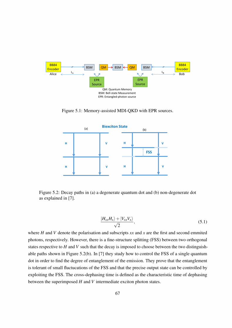
BB84 Encoder QM QM
BB84 EncoderBSM
LBLAAlice Bob
QM: Quantum MemoryBSM: Bell-state MeasurementEPR: Entangled-photon source
BSM BSM
EPRSource
EPRSource
Figure 5.1: Memory-assisted MDI-QKD with EPR sources.
H
H
V
Biexciton State
V
H
H
FSS
V
V
(a) (b)
Figure 5.2: Decay paths in (a) a degenerate quantum dot and (b) non-degenerate dotas explained in [7].
|HxxHx〉+ |VxxVx〉√2
, (5.1)
where H and V denote the polarisation and subscripts xx and x are the first and second emmitedphotons, respectively. However, there is a fine-structure splitting (FSS) between two orthogonalstates respective to H and V such that the decay is imposed to choose between the two distinguish-able paths shown in Figure 5.2(b). In [7] they study how to control the FSS of a single quantumdot in order to find the degree of entanglement of the emission. They prove that the entanglementis tolerant of small fluctucations of the FSS and that the precise output state can be controlled byexploiting the FSS. The cross-dephasing time is defined as the characteristic time of dephasingbetween the superimposed H and V intermediate exciton photon states.
67

The biexciton and ground states do not evolve in time, however, the intermediate state of thefirst emitted photon is considered a superposition of two exciton-photon states with S being theirenergy separation difference equal to the FSS (see Figure 5.2(b)). The difference in phase createdby the two states is equal to St/h, where t is the random time spent in the middle states, and thefinal state is given by the following state
|φ〉= |HxxHx〉+ exp(iSt/h)|VxxVx〉√2
. (5.2)
If one averages over t, then the generated EPR state will be in the subspace spanned by
|Φ±〉= |HxxHx〉± |VxxVx〉√2
. (5.3)
In [7], there is an analysis that proves that entanglement of the photon pair is robust to thedephasing of the exciton state for the first-order coherence time of either single photon. In [7]the authors include the effects from background light, spin-scattered light and dephased light.The background light relates to uncorrelated polarised states of light that comes from other thanthe dot areas. The spin-scattering relates to the spin being scattered, after the emission of thefirst photon thus leading to uncorrelated polarisation, and dephasing is related to the randomizedphase between the two superimposed eigenstates. By accounting for characteristic times of spinscattering, cross-dephasing and radiative recombination, the source output state in the rectilinearbasis |HxxHx〉, |VxxVx〉 is given by
ρQdot =
A′ 0 0 H ′
0 B′ 0 00 0 C′ 0
H ′ 0 0 D′
(5.4)
where A′,B′,C′,D′ represent the probabilities for, respectively, the states |HH〉〈HH|, |HV 〉〈HV |,|V H〉〈V H| and |VV 〉〈VV |, whereas H ′ is the probability for the states |HH〉〈VV | and |VV 〉〈HH|.In order to analyse the system in the most general form, in our analysis, we assume the followinggeneral density matrix for our EPR source.
ρEPR =
A E G H
E B K L
G K C F
H L F D
(5.5)
68

where A,B,C,D, respectively, represent the probabilities for the Bell states |Φ+〉〈Φ+|, |Φ−〉〈Φ−|,|Ψ+〉〈Ψ+|, |Ψ−〉〈Ψ−|.This matrix is in the Bell basis, i.e., from left to right are the columnscorrespond to |Φ+〉, |Φ−〉, |Ψ+〉, |Ψ−〉, where
|Φ±〉= |HH〉± |VV 〉√2
(5.6)
and|Ψ±〉= |HV 〉± |V H〉√
2. (5.7)
Moving on to the next subsection we want to describe the protocol in which we have indirectlyheralding QMs in the memory-assisted MDI-QKD by using EPR sources as taken from the specialcases of the matrix in (5.5). We consider that the main entangled state generated by the quantumdot in [7] is given by Equation (5.2). The main components are generated by the HH photonsand VV terms with a time difference in the subspace due to the cross-dephasing effect, thus therecould be a mixture of the Bell states, |Φ+〉 and |Φ−〉.
5.4 Key rate analysis of MDI vs setup inefficiencies
In Figure 5.1 Alice and Bob send single photon states encoded as in BB84 polarisations. Simulta-neously, each EPR source generates entangled photon pairs and sends one photon towards theside-BSM and the other photon towards the QM. The side-BSM heralds the teleportation of theusers state to the QM. Here, we implicitly assume that storing a photon, generated by the localEPR source, into the QM can be done efficiencly. The state of the EPR source is considered as theone given by Equation 5.5. However since each single photon sent by Alice and Bob are in the Z
or X basis we need to apply the rotation matrix from Bell basis to the H/V basis, given by
R =
1√2
0 0 1√2
1√2
0 0 − 1√2
0 1√2
1√2
0
0 1√2− 1√
20
(5.8)
to obtainρEPR;HV = R†(ρEPR)R, (5.9)
which is the initial state of the EPR source in the HV basis.
In our rate analysis, we use the modelling introduced in Chapter 3 to break the setup in Figure
69

5.1 to smaller systems. In fact, the setup in Figure 5.1 can be thought as three sub-systems ofthe type we discussed in Chapter 3. The first and second subsystems are the MDI-QKD setupsbetween the users and the corresponding photon P generated by the EPR source; see Figure5.3. The third sub-system is the middle BSM on retrieved photons, from QMs. All these threesub-systems have the same structure as the MDI-QKD with imperfect sources discussed in Chapter3. We can then use our results there in our key rate analysis here.
EPRSource
QMBSMBB84
EncoderQM: Quantum Memory
BSM: Bell-state MeasurementEPR: Entangled-photon sourceP M
LA
Figure 5.3: Side BSM operation for Alices’ side. We can consider a similar structurefor the Bob’s side. The EPR source is located next to the QM and the measurementmodule.
In Figure 5.3, the initial density matrix including Alice single photon is given by
ρ(m)AE;K = ρ
(m)A;K⊗ρEPR;HV , (5.10)
where m = 0,1 is the transmitted bit by Alice and K denotes the chosen basis by Alice. TheEPR state consists of the memory photon and the photon that interferes at the BSM with Alices’(Bob’s) as seen in Figure 5.3 and is given by
ρEPR;HV = ∑n,l,r,s=H,V
pn,l,r,s|nl〉PM〈rs|, (5.11)
where pn,l,r,s is the corresponding terms to the matrix given by Equation (5.9). From the aboveEquation we have that the full initial density matrix becomes
70
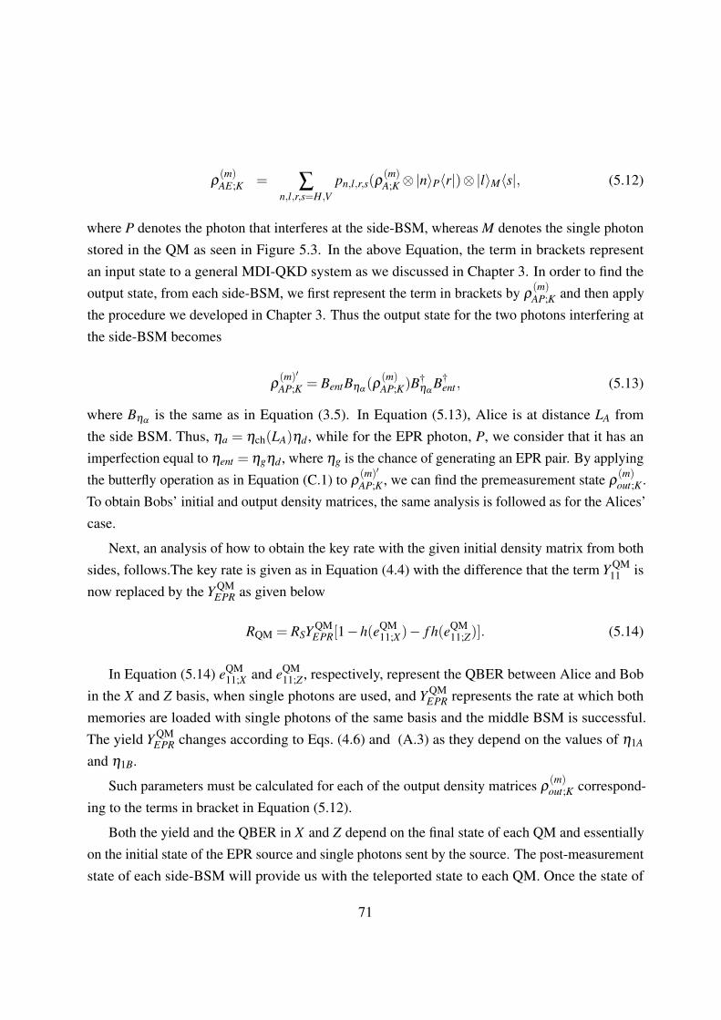
ρ(m)AE;K = ∑
n,l,r,s=H,Vpn,l,r,s(ρ
(m)A;K⊗|n〉P〈r|)⊗|l〉M〈s|, (5.12)
where P denotes the photon that interferes at the side-BSM, whereas M denotes the single photonstored in the QM as seen in Figure 5.3. In the above Equation, the term in brackets representan input state to a general MDI-QKD system as we discussed in Chapter 3. In order to find theoutput state, from each side-BSM, we first represent the term in brackets by ρ
(m)AP;K and then apply
the procedure we developed in Chapter 3. Thus the output state for the two photons interfering atthe side-BSM becomes
ρ(m)′
AP;K = BentBηα(ρ
(m)AP;K)B
†ηα
B†ent , (5.13)
where Bηαis the same as in Equation (3.5). In Equation (5.13), Alice is at distance LA from
the side BSM. Thus, ηa = ηch(LA)ηd , while for the EPR photon, P, we consider that it has animperfection equal to ηent = ηgηd , where ηg is the chance of generating an EPR pair. By applyingthe butterfly operation as in Equation (C.1) to ρ
(m)′
AP;K , we can find the premeasurement state ρ(m)out;K .
To obtain Bobs’ initial and output density matrices, the same analysis is followed as for the Alices’case.
Next, an analysis of how to obtain the key rate with the given initial density matrix from bothsides, follows.The key rate is given as in Equation (4.4) with the difference that the term Y QM
11 isnow replaced by the Y QM
EPR as given below
RQM = RSY QMEPR[1−h(eQM
11;X)− f h(eQM11;Z)]. (5.14)
In Equation (5.14) eQM11;X and eQM
11;Z , respectively, represent the QBER between Alice and Bobin the X and Z basis, when single photons are used, and Y QM
EPR represents the rate at which bothmemories are loaded with single photons of the same basis and the middle BSM is successful.The yield Y QM
EPR changes according to Eqs. (4.6) and (A.3) as they depend on the values of η1A
and η1B.
Such parameters must be calculated for each of the output density matrices ρ(m)out;K correspond-
ing to the terms in bracket in Equation (5.12).
Both the yield and the QBER in X and Z depend on the final state of each QM and essentiallyon the initial state of the EPR source and single photons sent by the source. The post-measurementstate of each side-BSM will provide us with the teleported state to each QM. Once the state of
71

each QM is known, we use the procedure outlined in Chapter 3 to calculate the success rate forthe middle BSM.
To find the final post-measurement state, first we need to apply in the same order all the aboveto Bob’s side and obtain his QM state right before the middle BSM measurement operation. Thefinal state of Bob’s QM can be obtained similarly.
5.5 Numerical results
In this section, we study the impact of different parameters on the secret key generation rate ofour scheme in different cases. We compare in a symmetric setup the QBER in X and Z bases andadditionally the secret key generation rate per transmitted pulse for different fidelities of the Bellstates generated from an EPR source assuming the users’ single-photon sources are ideal. Wecontinue by comparing different Werner states being produced by an imperfect EPR source interms of the QBER in X and Z bases and the key rate for both the asymmetric and symmetricsetups and finally compare the results between the two setups. Next we compare the symmetricand asymmetric setups again in terms of the secret key rate and QBER versus distance. All resultshave been obtained assuming an error correction inefficiency f = 1.16, 0.2 dB per km of loss inthe channel, detection efficiency of ηd = 0.15, dark count rate per pulse pdc = 1×10⁻⁶, and nomisalignments, i.e., edA = edB = 0 and efficiency for an EPR source ηg = 1. For the memories itis assumed that the reading efficiency ηr = 1, reading time τr = 0, writing time τw = 1×10⁻⁶
sec. The single photon repetition rate RS = 1×10⁻⁶sec and there is no memory decay..
• Case 1: A mixture of |Φ+〉 and |Φ−〉
In a realistic scenario it is assumed that at the state-preparation stage of the EPR sourcethere are imperfections. In this scenario we study the case where there is a mixture of Bellstates as part of imperfections. More specifically we take a mixture of Φ+ and Φ− thus theinitial density matrix of the EPR source in the Bell basis is equal to
ρEPR;Φ =
A 0 0 00 B 0 00 0 0 00 0 0 0
, (5.15)
where A is the probability for the Bell state |Φ+〉= |HH〉+|VV 〉√2
and B is the probability for
Bell state |Φ−〉= |HH〉−|VV 〉√2
. Equivalently, we have
72

ρEPR;Φ = F |Φ+〉〈Φ+|+(1−F)|Φ−〉〈Φ−|, (5.16)
Memory-assisted:--- F=60% --- F=70%--- F=80%--- F=90%
Figure 5.4: QBER in X basis versus distance for different fidelities of a Bell state.
where F = A. As we can see from Figure 5.4 for different values of fidelity, F , for theinput state, the QBER in X basis increases as the fidelity of the main EPR state (in thiscase |Φ+〉) decreases. The reason is that the mixture of the two Bell states, creates falseerrors on the detectors both in the side-BSMs and the middle BSM operations. Thus theprobability of having an error is high. For fidelities of F=60% of |Φ+〉 the QBER is veryhigh at the sources side, making the protocol insecure. For fidelities higher than 60%, theQBER is constant up to a distance of 300 km and then increases abruptly due to the darkcount effects being dominant over the correct clicks.
In Figure 5.5, for similar fidelities of the input state, we compare the system with its no-memory counterpart. We can see that for fidelities lower than 70% the memory-assistedMDI-QKD has a low performance due to the QBER being high from the imperfection in theEPR source. For a fidelity equal to 80% the memory-assisted MDI-QKD can outperformits no-memory counterpart between rougly 90 km to 250 km in terms of key rate pertransmitted pulse, however it reaches shorter distances in comparison to the latter one. Forfidelities higher than 80% our memory-assisted scheme can outperform the no-memory
73

Memory-assisted:--- F=60% --- F=70%--- F=80% --- F=90%--- F=100% No memory--- F=100%
Figure 5.5: Key rate versus distance for different fidelities of a Bell state.
system both in terms of distance and key rate per pulse, (for F=100% reaches up to 360 kmin Figure 5.5).
• Case 2: Werner states
In a different scenario to the above, we are studying the case where there is a mixture of thefour maximally entangled states as given by the Werner state below
ρEPR = F |Φ+〉〈Φ+|+ (1−F)
3(|Φ−〉〈Φ−|+ |Ψ+〉〈Ψ+|+ |Ψ−〉〈Ψ−|). (5.17)
In this scenario, we are studying the case of having a mixture of Bell states as we considerimperfections at the state-preparation stage of the EPR source. In the matrix format, theinitial density matrix of the EPR source is equal to
ρEPR;W =
F 0 0 00 (1−F)/3 0 00 0 (1−F)/3 00 0 0 (1−F)/3
. (5.18)
74

--- F=93% --- F=95%--- F=97% --- F=99%
Figure 5.6: QBER in X basis versus distance for different fidelities of a Werner state.
We have taken fidelities ranging from 93% to 99%, meaning that the mixture of othermaximally entangled states is kept as low as possible and having the main state generatedby an EPR source at the highest possible fidelity. From Figure 5.6 we can see that thelower the fidelity is, the higher the QBER becomes. At values less than 93% our procolis insecure because the error rate at the source’s side becomes significantly higher than11%. For fidelities kept well above 93%, our protocol is functional, with the dark counteffect becoming the main source of QBER at distances roughly above 300 km. Additionallyas a comparison to the previous case, where only a mixture of two states was included inmodulation errors, the QBER in this case is much higher. This is due to the fact that theerrors at the modulation stage is now higher as there are three possible states contributing toerror clicks at the side-BSM and BSM stages.
In Figure 5.7 we make a comparison with similar values of fidelities and compare themto the no-memory case. For fidelities equal to 93% our protocol behaves better within theregion of roughly 100 km to 260 km in terms of key rate per pulse, however the no-memorysystem reaches longer distances in this case (320 km). For values of equal and higherfidelity than 95% all our memory-assisted cases, outperform the no-memory case, in bothkey rate per pulse and security distance. At 95% fidelity, it reaches up to roughly 325 km
75

Memory-assisted:--- F=93% --- F=95%--- F=97% --- F=99%--- F=100% No memory--- F=100%
Figure 5.7: Key rate versus distance for different fidelities of a Werner state.
and for 99% it reaches up to 360km.
5.6 Conclusion
In this chapter we analysed a memory-assisted MDI-QKD with EPR sources for indirectlyheralding QMs mentioned in Chapter 4. To avoid the multiple excitation effect that ensemblebased memories are prone to, which eventually deteriorate the key rate performance in a memory-assisted MDI-QKD scenario, we proposed instead the usage of EPR sources. The generation ofentangled photon pairs can be achieved in two ways, the SPDC and quantum dots. The SPDCmethod has the disadvantage of generating multiple photons itself, therefore not improving theperformance. The quantum dots can however both avoid the multi-photon components and alsoperform adequately at high rates on the order of GHz. They have been fully studied in terms oftiming imperfections, i.e., cross-dephasing, background light and spin-scattering and still functionsufficiently well under certain assumptions as an imperfect EPR source. In our protocol weconsidered that the EPR source could tolerate, at the state-preparation stage, some modulationerrors and our protocol would still be able to outperform the no-memory QKD schemes.
We provided a detailed analysis on how to retrieve the state of the two memories under the
76

assumption that the EPR source generates a generalised state with a mixture of all Bell states. Wehave considered different cases for the initial state and studied how the performance of the keyrate versus distance and QBER is affected. In the first case we considered only Bell states thatexpected to be generated by a quantum dot source. We assumed that one state has a lower chanceto be generated. As the fidelity of the dominant state is increased, the key rate performance issignificantly increased compared to the no-memory case. Additionally the QBER is decreasedaccordingly as the chance of having an error from the side-BSMs and middle BSM and also at themodulation stage are low.
In the another case, we studied how the fidelity of Werner states affects key rate and QBERversus distance performance. The lower the fidelity of the leading generated state, the higherthe QBER at the source’s side and the shorter the security distance becomes. For a fidelity of93% our scheme offers higher rates over distances of roughly 100 km to 260 km however, theno-memory system reaches longer distances in this case (320 km). For fidelities > 95% all ourmemory-assisted cases outperform the no-memory case, in both key rate per pulse and securitydistance. At 95% , the security distance reaches up to roughly 325 km and at 99% it reachesup to 360 km. Therefore we conclude that an entangled photon source with high fidelity in ourmemory-assisted MDI-QKD can successfully outperform, in terms of key rate per pulse and thesecurity distance, conventional no-memory MDI-QKD schemes.
77

Chapter 6
Summary and future work
In this thesis we addressed the impact of quantum memories employed in an MDI-QKD scenarioto improve its performance over no-memory conventional QKD systems, through the analysis ofthe secret key rate. We considered a detailed analysis of non-idealities at the source’s side as wellas on the memory side.
We firstly analysed the effects of a single-photon source being imperfect at the state-preparationstage and how it would affect the key rate and QBER versus distance. We made a comparisonbetween an ideal MDI-QKD and a conventional BB84 system and an source MDI-QKD systemwith imperfect sources to study the performance in each case when modulation errors are accountedfor.
Then we continued by introducing a new MDI-QKD system that used QMs in its setup. InChapter 4, we meticulously considered imperfections in the QMs in terms of decoherence andstorage time and how their addition to the MDI-QKD affects the key rate versus distance. Yetconsidering the strict requirements in terms of coherence times and writing times of the QMs, weproposed an alternative system using ensemble-based QMs. The ensemble-based memories, fullfilthe criteria we set for having large storage-bandwidth product and short access and entanglingtimes. However, we found that due to the multiple excitation effect of the ensemble based QMs,we could no longer outperform the no-memory systems. Therefore we proposed an alternativesystem, using EPR sources.
This system consisted of EPR sources used in our memory-assisted MDI-QKD protocol. For
78

a realistic scenario, we included imperfections at the EPR source’s state-preparation stage as wedid similarly for single-photon sources in Chapter 3. The quantum dot is the best candidate asan entangled photon source as it has minimum multiple photon components and can be used ondemand. By including modulation errors on the EPR source’s side, we estimated the maximumachievable distance for the memory-assisted MDI-QKD system. We found that when the fidelityof these entangled photon pairs has kept at a sufficiently high value, the system behaved quitepromising against its no-memory conventional counterparts.
Future directions of research that I am planning to pursue include:
• In Chapter 5 we have analysed how the protocol performs under the assumption of singlephoton states used. In the future, as an extension to the same protocol we apply the decoy-state method to study how it behaves under certain assumptions, making it still possible toretrieve high key rates and longer secure distances when compared to no-memory protocols.
• Our work has analysed the schemes for Chapter 4 and 5 under the assumption of usinginfinitely many keys. As a more practical assumption, we will study the finite key analysison all protocols described in Chapters 4 and 5 and compare these to tight security boundsfor practical decoy state QKD protocols.
• We analyse how our memory-assisted MDI-QKD performs using specific quantum mem-ories that are currently advanced in technological terms to be suitable candidates for therequirements we have set in Chapters 4 and 5.
• In Chapter 5 we have not accounted for the required coherence times for the QMs. In thenext step we will study the coherence time requirements in the memory-assisted MDI-QKDwith EPR sources for a more practical implementation of the protocol.
Our results pave the way for a promising future work to be further pursued. This trust-freeprotocol could be used as part of a quantum repeater system that could lead to a future quantumnetwork. Such a network could potentially be implemented by a number of imperfect quantummemories, however the key rate would remain at high rates.
79

Appendix A
Loading process
The loading process in the setups of Figures 2.5(a) and 2.5(b) are probabilistic ones, with twogeometric random variables NA and NB playing the major role. Suppose the success probabilityfor each loading attempt corresponding to these random variables is, respectively, given by ηA
and ηB. Then, we obtain the following probability distribution for |NA−NB|:
Pr(|NA−NB|= k) = [(1−ηA)k +(1−ηB)
k]P0, k > 0, (A.1)
whereP0 = Pr(NA = NB) =
ηAηB
ηA +ηB−ηAηB. (A.2)
Using the above expressions, we then obtain
NL(ηA,ηB) = E{max(NA,NB)}
=12
E{|NA−NB|+NA +NB}
=12
[ηA(1−ηB)
ηB(ηA +ηB−ηAηB)+
ηB(1−ηA)
ηA(ηA +ηB−ηAηB)+
1ηA
+1
ηB
].
(A.3)
80

Moreover,
E{exp(−|NA−NB|δ )}= P0
[1
1− e−δ (1−ηA)+
11− e−δ (1−ηB)
−1]
(A.4)
and the average storage time, Tst , is given by
Tst = E{|NA−NB|}T =ηA(1−ηB)T
ηB(ηA +ηB−ηAηB)+
ηB(1−ηA)TηA(ηA +ηB−ηAηB)
. (A.5)
Finally, we can show that
Pr{NA ≥ NB}=ηB
1− (1−ηA)(1−ηB)= 1−Pr{NA < NB} (A.6)
and
SA<B(δ ) ≡∞
∑1=na<nb
Pr{NA = na,NB = nb}exp[(na−nb)δ ]
=ηAηB(1−ηB)e−δ
[1− (1−ηB)e−δ ][1− (1−ηA)(1−ηB)]. (A.7)
81

Appendix B
Misalignment Parameters
In this Appendix, we obtain the misalignment probability for each of the setups in Figures2.5(a) and 2.5(b). Let us first consider the directly heralding memory case in the Z basis andassume loading probabilities ηA and ηB for Alice’s and Bob’s memories. Suppose the legitimatestate is |sH〉〈sH |. Assuming setup misalignment probabilities edK , K = A,B, for leg K of Figure2.5(a), in the absence of background counts, the stored state in memory K will become ρd0 =
(1− edK)|sH〉〈sH |+ edK|sV 〉〈sV |. Now, including the background counts, the memory state willbecome
ρdZ = [1− e(K)BG ]ρd0 + e(K)
BG|sH〉〈sH |+ |sV 〉〈sV |
2, (B.1)
where e(K)BG = 1−e−ηw pBG
ηK, K = A,B, is the probability that our memory has been loaded by a
background (unpolarized) photon conditioned on a successful loading. The total misalignmentprobability in the Z basis for the Alice’s and Bob’s memory is then given by
e(K)dZ = edK(1− e(K)
BG )+ e(K)BG/2, K = A,B, for directly heralding QMs. (B.2)
Now, let’s assume the legitimate state, in the X basis, is |s+〉〈s+|, where |s±〉= (|sH〉± |sV 〉)/√
2.Right after a successful loading, the state of the memory is then given by
ρdX(0) = [1− e(K)BG ]ρ
′d0 + e(K)
BG|sH〉〈sH |+ |sV 〉〈sV |
2(B.3)
82

where ρ ′d0 = (1− edK)|s+〉〈s+|+ edK|s−〉〈s−|. If memory A is the late memory, i.e., if NA ≥ NB,then there will be no dephazing errors, in which case, e(A)dX = e(A)dZ . If it is the early memory,however, the dephazing operation in Equation (4.3) will act on ρdX(0) to give us
ρdX(t) = [1− e(K)BG ]ρ
′d0(t)+ e(K)
BG|sH〉〈sH |+ |sV 〉〈sV |
2, (B.4)
where ρ ′d0(t) = [(1−edK)p(t)+edK(1− p(t))]|s+〉〈s+|+[edK p(t)+(1−edK)(1− p(t))]|s−〉〈s−|.The misalignment probability is then given by
e(K)dX = e(K)
dZ +βAe(K)deph, (B.5)
where βK = (1−2edK)(1− e(K)BG ), K = A,B, and
e(A)deph =
{0 NA ≥ NB
(1/2)[1− exp(−|NA−NB|T/T2)] NA < NB, (B.6)
where NA and NB are geometric random variables with success probabilities ηA and ηB. Byaveraging over these variables, we obtain
E{e(A)dX }= e(A)dZ +βAE{e(A)deph}, (B.7)
whereE{e(A)deph}= [Pr{NA < NB}−SA<B(T/T2)]/2, (B.8)
which can be obtained from equations (A.6) and (A.7). One can obtain similar expressions fore(B)dX by swapping A and B in equations (B.6)–(B.8).
To calculate E{eQMdX } from Equation (4.11), the final remaining term is given by
E{e(A)dX e(B)dX }= e(A)dZ e(B)dZ +βAE{e(A)deph}e(B)dZ +βBE{e(B)deph}e
(A)dZ , (B.9)
where we used the fact that e(A)dephe(B)deph = 0, as one of the two terms is always zero regardless ofthe values of NA and NB.
In the case of indirectly heralding QMs, we assume that each erroneous click on the sideBSMs will effectively result in a flip to the corresponding QM state, and can also be modeled asmisalignment. This assumption is valid at low distances where majority of errors are caused by
83

the setup misalignment. We then obtain
e(K)dZ = e11;Z(ηdηch(LK),ηdηent,edK), K = A,B, (B.10)
for indirectly heralding QMs, where e11;Z can be calculated from Equation (2.22) at an equivalentdark count rate of γdc +ηdγBG/2. At long distances, most errors originate from dark countsor background photons, whose effective misalignment effect will approach half of e11;Z in theabove equation. As a conservative assumption, we use the expression in Equation (B.10) for alldistances.
All other terms in Equations (4.10) and (4.11) can be obtained following the same expressionsin Equations (B.5)–(B.9) at βK = 1−2e(K)
dZ , for K = A,B, and using Equation (B.10) for e(K)dZ .
84

Appendix C
Butterfly operator
In this Appendix, we obtain the butterfly operator BBF that acts on the input state for the setupgiven in Figure 3.1. Let us first consider the input state is taken from Equation (5.10) accordinglyfor Alice and Bob including their EPR state for each side. This input state after modeling the pathloss as in Figure 3.2 has three possible outcomes in polarisation, i.e., in the Z basis we have theH,V photon polarisations and the vacuum state |0〉. Hence our input state is a bipartite systemof a combination of 3 possible outcomes in each case leading to a 9×9 system. The analyticalexpression of Alice and Bob’s input state is after modeling the path loss is given by
ρ(m)′
A;Z = η(α|H〉A〈H|+ γ|V 〉A〈V |)
+ β |H〉A〈V |+β∗|V 〉A〈H|)
= ηAρ(m)A;Z +(1−ηA)|0〉A〈0| (C.1)
and similarly for Bob
ρ(n)′B;Z = η(α|H〉B〈H|+ γ|V 〉B〈V |)
+ β |H〉B〈V |+β∗|V 〉B〈H|)
= ηBρ(n)B;Z +(1−ηB)|0〉B〈0|. (C.2)
85

ΨA ΨB BBF (ΨAΨB)
|H〉 |H〉 [|2〉DH1|0〉DH2 ,V1 ,V2
−|0〉DH1 ,V1 ,V2|2〉DH2
]/√
2|V 〉 [|1〉DV1
|1〉DH2|0〉DH1 ,V2
−|1〉DV2|1〉DH2
|0〉DH1 ,V1+ |1〉DV1
|1〉DH1|0〉DH2 ,V2
−|1〉DH1|1〉DV2
|0〉DH2 ,V1]/2
|0〉 [|1〉DH2|0〉DH1 ,V1 ,V2
+ |0〉DH2 ,V1 ,V2|1〉DH1
]/√
2
|V 〉 |H〉 [|1〉DV2|1〉DH2
|0〉DH1 ,V1−|1〉DV1
|1〉DH2|0〉DH1 ,V2
−|1〉DV1|1〉DH1
|0〉DH2 ,V2+ |1〉DH1
|1〉DV2|0〉DH2 ,V1
]/2|V 〉 [|2〉DV1
|0〉DH2 ,H1 ,V2−|0〉DH1 ,H2 ,V1
|2〉DV2]/√
2|0〉 [|1〉DV1
|0〉DH1 ,H2 ,V2+ |0〉DH1 ,H2 ,V1
|1〉DV2]/√
2
|0〉 |H〉 [|1〉DH1|0〉DH2 ,V1 ,V2
−|0〉DH1 ,V1 ,V2|1〉DH2
]/√
2|V 〉 [|1〉DV1
|0〉DH1 ,H2 ,V2−|0〉DH1 ,H2 ,V1
|1〉DV2]/√
2|0〉 |0〉DH1
|0〉DH2|0〉DV1
|0〉DV2
Table C.1: Butterfly operation on input state
The butterfly operator BBF will be given analytically for the above joint state according to Equation(5.10) as shown in the Table C.1.
86

Bibliography
[1] C. H. Bennett and G. Brassard. Quantum cryptography: Public key distribution and cointossing. In Proceedings of IEEE International Conference on Computers, Systems, and
Signal Processing, pages 175–179, Bangalore, India, 1984. IEEE.
[2] G. Brassard, N. Lutkenhaus, T. Mor, and B. C. Sanders. Limitations on practical quantumcryptography. Phys. Rev. Lett., 85:1330–1333, Aug 2000.
[3] A. K. Ekert. Quantum cryptography based on Bell’s theorem. Phys. Rev. Lett. , 67:661,1991.
[4] Hoi-Kwong Lo, Marcos Curty, and Bing Qi. Measurement-device-independent quantumkey distribution. Phys. Rev. Lett., 108:130503, March 2012.
[5] K. F. Reim, P. Michelberger, K. C. Lee, J. Nunn, N. K. Langford, and I. A. Walmsley.Single-photon-level quantum memory at room temperature. Phys. Rev. Lett., 107:053603,Jul 2011.
[6] N.L. Piparo, M. Razavi, and C. Panayi. Measurement-device-independent quantum keydistribution with ensemble-based memories. Selected Topics in Quantum Electronics, IEEE
Journal of, 21(3):138–147, May 2015.
[7] A. J. Hudson, R. M. Stevenson, A. J. Bennett, R. J. Young, C. A. Nicoll, P. Atkinson,K. Cooper, D. A. Ritchie, and A. J. Shields. Coherence of an entangled exciton-photon state.Phys. Rev. Lett., 99:266802, Dec 2007.
[8] G. S. Vernam. Cipher printing telegraph systems for secret wire and radio telgraphiccommunications. J. AIEE, 45:109–115, 1926.
[9] Cipher A. Deavours and Louis Kruh. Machine Cryptography and Modern Cryptanalysis.Artech House, Inc., Norwood, MA, USA, 1985.
87

[10] Whitfield Diffie and Martin E. Hellman. New directions in cryptography, 1976.
[11] R. L. Rivest, A. Shamir, and L. Adleman. A method for obtaining digital signatures andpublic-key cryptosystems. Commun. ACM, 21(2):120–126, February 1978.
[12] M. Gardner. Mathematical games, a new kind of cipher that would take millions of years tobreak. Sci. Am, 237:120, 1977.
[13] A. Shamir. Cryptographic hardware and embedded systems: first international worskhop.Proceedings of CHES’99, WOrcester, MA, USA, Lecture, 1717, 1999.
[14] et al. T. Kleinjung, P. Zimmermann. Factorization of a 768-bit rsa modulus. Factorization of
a 768-bit RSA modulus, 6223:333–350, February 2010.
[15] Peter W. Shor. Polynomial-time algorithms for prime factorization and discrete logarithmson a quantum computer. SIAM J. on Computing, pages 1484–1509, 1997.
[16] M. Hendrych M. Dusek, Norbert Lutkenhaus. Quantum cryptography. Progress in Optics,pages 381–454, 2006.
[17] Claude E. Shannon. Communication Theory of Secrecy Systems. Bell Systems Technical
Journal, 28:656–715, 1949.
[18] W. K. Wootters and W. H. Zurek. A single quantum cannot be cloned. Nature, 299(5886):802–803, October 1982.
[19] D. Gottesman, Hoi-Kwong L., N. Lutkenhaus , and J. Preskill. Security of quantum keydistribution with imperfect devices. In Information Theory, 2004. ISIT 2004. Proceedings.
International Symposium on, pages 136–, June 2004.
[20] V. Scarani, A. Acın, G. Ribordy, and N. Gisin. Quantum cryptography protocols robustagainst photon number splitting attacks for weak laser pulse implementations. Phys. Rev.
Lett., 92:057901, Feb 2004.
[21] Won-Young Hwang. Quantum key distribution with high loss: Toward global securecommunication. Phys. Rev. Lett. , 91:057901, August 2003.
[22] Charles H. Bennett, Gilles Brassard, and N. David Mermin. Quantum cryptography withoutbell’s theorem. Phys. Rev. Lett., 68:557–559, Feb 1992.
[23] John S. Bell. On the Einstein-Podolsky-Rosen paradox. Physics, 1:195–200, 1964.
88

[24] John F. Clauser, Michael A. Horne, Abner Shimony, and Richard A. Holt. Proposedexperiment to test local hidden-variable theories. Phys. Rev. Lett., 23:880–884, Oct 1969.
[25] Bing Qi, Chi-Hang Fred Fung, Hoi-Kwong Lo, and Xiongfeng Ma. Time-shift attack inpractical quantum cryptosystems. Quant. Inf. Comput., 7:073, 2007.
[26] Yi Zhao, Chi-Hang Fred Fung, Bing Qi, Christine Chen, and Hoi-Kwong Lo. Experimentaldemonstration of time-shift attack against practical quantum key distribution systems. Phys.
Rev. A, 78:042333, 2008.
[27] L. Lydersen, C. Wiechers, C. Wittmann, D. Elser, J. Skaar, and V. Makarov. Hackingcommercial quantum cryptography systems by tailored bright illumination. Nature photonics,4(10):686–689, 2010.
[28] C Wiechers, L Lydersen, C Wittmann, D Elser, J Skaar, Ch Marquardt, V Makarov,and G Leuchs. After-gate attack on a quantum cryptosystem. New Journal of Physics,13(1):013043, 2011.
[29] Henning Weier, Harald Krauss, Markus Rau, Martin Furst, Sebastian Nauerth, and HaraldWeinfurter. Quantum eavesdropping without interception: an attack exploiting the dead timeof single-photon detectors. New Journal of Physics, 13(7):073024, 2011.
[30] N. Jain, C. Wittmann, L. Lydersen, C. Wiechers, D. Elser, C. Marquardt, V. Makarov, andG. Leuchs. Device calibration impacts security of quantum key distribution. Phys. Rev. Lett.,107:110501, Sep 2011.
[31] Hoi-Kwong Lo, Marcos Curty, and Bing Qi. Measurement-device-independent quantumkey distribution. Phys. Rev. Lett., 108:130503, Mar 2012.
[32] Samuel L. Braunstein and Stefano Pirandola. Side-channel-free quantum key distribution.Phys. Rev. Lett., 108:130502, Mar 2012.
[33] E. Biham, B. Huttner, and T. Mor. Quantum cryptographic network based on quantummemories. Phys. Rev. A, 54(4):2651, 1996.
[34] Xiongfeng Ma, Chi-Hang Fred Fung, and Hoi-Kwong Lo. Quantum key distribution withentangled photon sources. Phys. Rev. A, 76:012307, Jul 2007.
89

[35] Yi Zhao, Chi-Hang Fred Fung, Bing Qi, Christine Chen, and Hoi-Kwong Lo. Quantumhacking: Experimental demonstration of time-shift attack against practical quantum-key-distribution systems. Phys. Rev. A, 78:042333, Oct 2008.
[36] F. Xu, B. Qi, and H. Lo. Experimental demonstration of phase-remapping attack in apractical quantum key distribution system. New Journal of Physics, 12(11):113026, 2010.
[37] Lars Lydersen, Carlos Wiechers, Christoffer Wittmann, Dominique Elser, Johannes Skaar,and Vadim Makarov. Hacking commercial quantum cryptography systems by tailored brightillumination. Nature Photonics, (4):686–689, 2010.
[38] Shuang Wang, Wei Chen, Jun-Fu Guo, Zhen-Qiang Yin, Hong-Wei Li, Zheng Zhou, Guang-Can Guo, and Zheng-Fu Han. 2 GHz clock quantum key distribution over 260 km of standardtelecom fiber. Opt. Lett., 37(6):1008–1010, March 2012.
[39] M. Sasaki, M. Fujiwara, and et. al. Field test of quantum key distribution in the Tokyo QKDNetwork. Opt. Exp., 19(11):10387–10409, 2011.
[40] M. Peev et al. The SECOQC quantum key distribution network in Vienna. New J. Phys.,11:075001, 2009.
[41] I. Choi, R. J. Young, and P. D. Townsend. Quantum information to the home. New J. Phys.,13:063039, June 2011.
[42] K. A. Patel, J. F. Dynes, I. Choi, A. W. Sharpe, A. R. Dixon, Z. L. Yuan, R. V. Penty, andA. J. Shields. Coexistence of high-bit-rate quantum key distribution and data on optical fiber.Phys. Rev. X, 2:041010, Nov. 2012.
[43] H.-J. Briegel, W. Dur, J. I. Cirac, and P. Zoller. Quantum repeaters: The role of imperfectlocal operations in quantum communication. Phys. Rev. Lett., 81(26):5932–5935, Dec. 1998.
[44] W. J. Munro, A. M. Stephens, S. J. Devitt, K. A. Harrison, and Kae Nemoto. Quantumcommunication without the necessity of quantum memories. Nat. Photon., 6:771–781, Oct.2012.
[45] L.M. Duan, M. D. Lukin, J. I. Cirac, and P. Zoller. Long-distance quantum communicationwith atomic ensembles and linear optics. Nature, 414(6862):413–418, November 2001.
90

[46] C. Panayi and M. Razavi. Measurement device independent quantum key distribution withimperfect quantum memories. In Tech. Digest, The Sixth International Conference on
Quantum, Nano and Micro Technologies, Rome, Italy, 2012.
[47] Silvestre Abruzzo, Hermann Kampermann, and Dagmar Bruß. Measurement-device-independent quantum key distribution with quantum memories. arXiv:1306.3095, 2013.
[48] Xiongfeng Ma and Mohsen Razavi. Alternative schemes for measurement-device-independent quantum key distribution. Phys. Rev. A, 86:062319, Dec. 2012.
[49] Mohsen Razavi, Marco Piani, and Norbert Lutkenhaus. Quantum repeaters with imperfectmemories: Cost and scalability. Phys. Rev. A, 80:032301, Sept. 2009.
[50] M. Razavi, K. Thompson, H. Farmanbar, Ma. Piani, and N. Lutkenhaus. Physical andarchitectural considerations in quantum repeaters. In Proc. SPIE, volume 7236, page723603, San Jose, CA, 2009.
[51] Mohsen Razavi, Nicolo Lo Piparo, Christiana Panayi, and David E. Bruschi. Architecturalconsiderations in hybrid quantum-classical networks (invited paper). In Iran Workshop on
Communication and Information Theory (IWCIT), pages 1–7, Tehran, Iran, 2013.
[52] Peter W. Shor and John Preskill. Simple proof of security of the BB84 quantum keydistribution protocol. Phys. Rev. Lett. , 85(2):441, July 2000.
[53] Daniel Gottesman and Hoi-Kwong Lo. Proof of security of quantum key distribution withtwo-way classical communications. IEEE Transactions on Information Theory, 49(2):457,2003.
[54] Xiongfeng Ma, Bing Qi, Yi Zhao, and Hoi-Kwong Lo. Practical decoy state for quantumkey distribution. Phys. Rev. A, 72:012326, July 2005.
[55] Xiongfeng Ma. Quantum cryptography. Thesis, 2008.
[56] Hoi-Kwong Lo, Xiongfeng Ma, and Kai Chen. Decoy state quantum key distribution.Phys. Rev. Lett. , 94:230504, June 2005.
[57] Hoi-Kwong Lo, H. F. Chau, and M. Ardehali. Efficient quantum key distribution schemeand a proof of its unconditional security. Journal of Cryptology, 18(2):133–165, 2005.
[58] Nikolina Ilic. The ekert protocol. Journal of Physics, 2007.
91

[59] Antonio Acın, Nicolas Brunner, Nicolas Gisin, Serge Massar, Stefano Pironio, and ValerioScarani. Device-independent security of quantum cryptography against collective attacks.Physical Review Letters, 98(23):230501, 2007.
[60] Thomas Jennewein, Christoph Simon, Gregor Weihs, Harald Weinfurter, and Anton Zeilinger.Quantum cryptography with entangled photons. Phys. Rev. Lett., 84:4729, 2000.
[61] Antonio Acın, Nicolas Brunner, Nicolas Gisin, Serge Massar, Stefano Pironio, and ValerioScarani. Device-independent security of quantum cryptography against collective attacks.Phys. Rev. Lett., 98:230501, Jun 2007.
[62] Xiongfeng Ma, Chi-Hang Fred Fung, and Mohsen Razavi. Statistical fluctuation analysisfor measurement-device-independent quantum key distribution. Phys. Rev. A, 86:052305,Nov 2012.
[63] Zhiyuan Tang, Kejin Wei, Olinka Bedroya, Li Qian, and Hoi-Kwong Lo. Experimentalmeasurement-device-independent quantum key distribution with imperfect sources. arXiv,2015.
[64] Kiyoshi Tamaki, Marcos Curty, Go Kato, Hoi-Kwong Lo, and Koji Azuma. Loss-tolerantquantum cryptography with imperfect sources. Phys. Rev. A, 90:052314, Nov 2014.
[65] S. Lloyd, M. S. Shahriar, J. H. Shapiro, and P. R. Hemmer. Long distance, unconditionalteleportation of atomic states via complete bell state measurements. Phys. Rev. Lett.,87:167903, Sep 2001.
[66] Mohsen Razavi and Jeffrey H. Shapiro. Long-distance quantum communication with neutralatoms. Phys. Rev. A, 73:042303, April 2006.
[67] Stephan Ritter, Christian Nolleke, Carolin Hahn, Andreas Reiserer, Andreas Neuzner,Manuel Uphoff, Martin Mucke, Eden Figueroa, Joerg Bochmann, and Gerhard Rempe. Anelementary quantum network of single atoms in optical cavities. Nature, 484:195–200, April2012.
[68] N. A. Peters, P. Toliver, T. E. Chapuran, and et. al. Dense wavelength multiplexing of1550nm QKD with strong classical channels in reconfigurable networking environments.New J. Phys., 11:045012, April 2009.
[69] T. E. Chapuran, P. Toliver, N. A. Peters, and et. al. Optical networking for quantum keydistribution and quantum communications. New J. Phys., 11:105001, Oct. 2009.
92

[70] M. Razavi. Multiple-access quantum key distribution networks. IEEE Trans. Commun.,60(10):3071–3079, 2012.
[71] J. R. Kuklinski, U. Gaubatz, F. T. Hioe, and K. Bergmann. Adiabatic population transfer ina three-level system driven by delayed laser pulses. Phys. Rev. A, 40:6741–6744, Dec 1989.
[72] Mohsen Razavi and Jeffrey H. Shapiro. Nonadiabatic approach to entanglement distributionover long distances. Phys. Rev. A, 75:032318, 2007.
[73] Christoph Simon, Hugues de Riedmatten, Mikael Afzelius, Nicolas Sangouard, HugoZbinden, and Nicolas Gisin. Quantum repeaters with photon pair sources and multimodememories. Phys. Rev. Lett., 98:190503, May 2007.
[74] Nicolo Lo Piparo and Mohsen Razavi. Long-distance quantum key distribution with imper-fect devices. Phys. Rev. A, 88:012332, Jul 2013.
[75] O. A. Collins, S. D. Jenkins, A. Kuzmich, and T. A. B. Kennedy. Multiplexed memory-insensitive quantum repeaters. Phys. Rev. Lett., 98:060502, Feb 2007.
[76] Xiao-Hui Bao, Andreas Reingruber, Peter Dietrich, Jun Rui, Alexander Duck, ThorstenStrassel, Li Li, Nai-Le Liu, Bo Zhao, and Jian-Wei Pan. Efficient and long-lived quantummemory with cold atoms inside a ring cavity. Nat. Phys., 8:517–521, May 2012.
[77] T. Chaneliere, D. N. Matsukevich, S. D. Jenkins, S.-Y. Lan, T. A. B. Kennedy, andA. Kuzmich. Storage and retrieval of single photons transmitted between remote quan-tum memories. Nature, 438:833–836, 2005.
[78] Jeyran Amirloo, Mohsen Razavi, and A. Hamed Majedi. Quantum key distribution overprobabilistic quantum repeaters. Phys. Rev. A, 82:032304, Sept. 2010.
[79] F. Marsili, V. B. Verma, J. A. Stern, S. Harrington, A. E. Lita, T. Gerrits, I. Vayshenker,B. Baek, M. D. Shaw, R. P. Mirin, and S. W. Nam. Detecting single infrared photons with93% system efficiency. Nat. Photon., 7:210–214, Feb. 2013.
[80] Ryan M. Camacho, Praveen K. Vudyasetu, and John C. Howell. Four-wave-mixing stoppedlight in hot atomic rubidium vapour. Nat. Photon., 3:103–106, Jan. 2009.
[81] A. Stute, B. Casabone, P. Schindler, T. Monz, P. O. Schmidt, B. Brandstatter, T. E. Northup,and R. Blatt. Tunable ion photon entanglement in an optical cavity. Nature, 485:482, May2012.
93

[82] A. Amari, A. Walther, M. Sabooni, M. Huang, S. Krll, M. Afzelius, I. Usmani, B. Lauritzen,N. Sangouard, H. de Riedmatten, and N. Gisin. Towards an efficient atomic frequency combquantum memory. Journal of Luminescence, 130(9):1579 – 1585, 2010.
[83] E. Saglamyurek, N. Sinclair, J. Jin, J. A. Slater, D. Oblak, F. Bussieres, M. George, R. Ricken,W. Sohler, and W. Tittel. Broadband waveguide quantum memory for entangled photons.Nature, 469:512–515, Jan. 2011.
[84] A. Stute and et. al. Tunable ionphoton entanglement in an optical cavity. Nature, 485:4,May 2012.
[85] Mohsen Razavi and Jeffrey H. Shapiro. Long-Distance Quantum Communication withNeutral Atoms, December 2005.
94