Embed Size (px)
Citation preview
NASA
Technical
Memorandum
NASA TM-108434
/H--3
DETAILED STUDY OF OXIDATION/WEAR MECHANISM
IN LOX TURBOPUMP BEARINGS
By T.J. Chase and J.P. McCarty
Propulsion LaboratoryScience and Engineering Directorate
December 1993
(NASA-TM-I08434) DETAILED STUDY OF
OXIDATION/WEAR MECHANISM IN LOXTURBOPUMP BEARINGS (NASA) 112 p
N94=2i580
Unclas
NASANational Aeronautics andSl::)ace Administration
George C. Marshall Space Flight Center
G3/37 0198065
MSFC • Form 3190 (Rev. May 1983)
https://ntrs.nasa.gov/search.jsp?R=19940017107 2020-05-28T17:16:40+00:00Z

Form Approved
REPORT DOCUMENTATION PAGE OMaNo.OZO*O,SS
n f r this collection of information is estimated to average 1 hour per response, including the time for reviewing instruCt ons, searching existing data sources,Public repOrting burde o , .......... _. =^ _ .;^_ ¢_.4 .^_mont = r_ardin, this burden estimate or any other aspect of this
" inin the data needed and comp et n ancl rev ew rig the Coller._lu_ M/ifl.urma_,v.. .=,_ _v,,, _ _ _7 _ • • --
gathe[,ng a;dn_oa_ta_ion 9includin _ su--estions for red uci_gg this burden, to Washington Headquarters Services, Directorate roT Informa.tl=onOL_=ra_onsand Rephrase12, S Jettersonc°ue_10n=u ...... " _ ,,_ '.__ ,_,_ _na_nv _nd tn the Office of Manaaementand Budget Paperwork Reduce on Pro ect(07u4-gltl_/,wasnlng_on, u_. zu_u_.DAVIS Highway. _u_(e _zu4. _r.ngtu,b v_ =¢¢v=_u=, - ..... '
1. AGENCY USE ONLY (Leave blank) 2. REPORT DATE 3. REPORT TYPE AND DATES COVERED
December 1993 Technical Memorandum
4. TITLE AND SUBTITLE 5. FUNDING NUMBERS
Detailed Study of Oxidation/Wear Mechanism in Lox Turbopump
Bearings6. AUTHOR(S)
T.J. Chase* and J.P. McCarty
7. PERFORMING ORGANIZATION NAME(S) AND ADDRESS(ES)
George C. Marshall Space Flight Center
Marshall Space Flight Center, Alabama 35812
9. SPONSORING/MONITORING AGENCY NAME(S)AND ADDRESS(ES)
National Aeronautics and Space Administration
Washington, DC 20546
8. PERFORMING ORGANIZATIONREPORT NUMBER
10. SPONSORING/MONITORINGAGENCY REPORT NUMBER
NASA TM-I08434
11. SUPPLEMENTARYNOTESPrepared by Propulsion Laboratory, Science and Engineering Directorate.
*National Research Council12a. DISTRIBUTION / AVAILABILITY STATEMENT
Unclas sifted--Unlimited
12b. DISTRIBUTION CODE
13. ABSTRACT (Maximum 200words)
Wear of 440C angular contact ball bearings of the phase II high pressure oxygen turbopump
(HPOTP) of the space shuttle main engine (SSME) has been studied by means of various advanced
nondestructive techniques (NDT) and modeled with reference to all known material, design, and
operation variables. Three modes dominating the wear scenario were found to be the adhesive/sheer
peeling (ASP), oxidation, and abrasion. Bearing wear was modeled in terms of the three modes. Lack-
ing a comprehensive theory of rolling contact wear to date, each mode is modeled after well-estab-
lished theories of sliding wear, while sliding velocity and distance are related to microsliding in ball-to-
ring contacts. Microsliding, stress, temperature, and other contact variables are evaluated with analyti-
cal software packages of SHABERTHrM/SINDArM and ADORE TM . Empirical constants for the models
are derived from NIST experiments by applying the models to the NIST wear data. The bearing wear
model so established precisely predicts quite well the average bail wear rate for the HPOTP bearings.
The wear rate has been statistically determined for the entire population of flight and development
bearings based on Rocketdyne records to date. Numerous illustrations are given.
14. SUBJECT TERMS
angular contact bearings, wear modeling, cryogenic bearings, lox turbopump
bearings, wear modes/mechanisms
17. SECURITY CLASSIFICATION 18, SECURITY CLASSIFICATION 19. SECURITY CLASSIFICATIONOF REPORT OF THIS PAGE OF ABSTRACT
Unclassifted Unclassifted Unclassifted
NSN 7540-01-280-S500
15. NUMBER OF PAGES
11516. PRICE CODE
NTIS
20. LIMITATION OF ABSTRAC1
Unlimited
Standard Form 298 (Rev 2-89)

±
.... k _i_r_--_ _
_A_E _ INTENTIONALLY_L:_:_:

TABLE OF CONTENTS
I. PURPOSE OF THE STUDY AND MAJOR OBJECTIVES ............................................
H. BACKGROUND ...............................................................................................................
lIl. BEARING ENVIRONMENT AND OPERATING CONDITIONS .................................
W. MATERIALS .....................................................................................................................
V. ANALYTICAL MODELING OF MAJOR WEAR MODES ...........................................
A. On Wear Modeling in General ...................................................................................B. Major Wear Modes Established for the Phase II Turbopump Bearings .....................
C. Adapting Models of Sliding Wear for Ball Bearings Operating in Lox .....................
1. ASP Mode--Microfatigue ....................................................................................2. Oxidation Mode .................................................. . .................................................
3. Abrasion Mode .....................................................................................................
D. Conversion of Linear Wear Rate "/" and Average Pressure "p" ................................
E. Evaluating Operational Variables With SHABERTH_/SINDA TM ...........................1. What SHABERTH TM is All About .......................................................................
2. Input Data and Related Matters ............................................................................
3. Computational Modes ...........................................................................................
4. Input Variables ......................................................................................................
5. Input Sensitivity and Output Verification .............................................................
6. Results and Their Relevance to Modeling ............................................................
F. Averaged Data for the Three Representative Cases ...................................................
G. Computing Ball Wear According to the Combined Model ........................................
VI. STATISTICAL ANALYSIS OF FIELD DATA AND APPRAISAL OF
BALL WEAR MEASUREMENT METHODOLOGY .....................................................
A. Statistical Analysis of Field Data ...............................................................................
B. Appraisal of Ball Wear Measurement Methodology ..................................................
VII. COMPARISON OF RESULTS OF WEAR MODELING TO WEAR STATISTICS .....
REFERENCES ...............................................................................................................................
APPENDIX A .............................................................................................................................
APPENDIX B ..............................................................................................................................
APPENDIX C ..............................................................................................................................
APPENDIX D ..............................................................................................................................
Page
1
4
5
5
56
9
9
9
9
9
10
10
1010
11
13
13
14
14
15
16
17
83
89
93
95
.°.
111
PI_GEOtNII PAGE BLANK NOT FILMED

LIST OF ILLUSTRATIONS
Figure
1.
,
.
,
.
,
,
8.
,
10.
11.
12.
13.
14.
15.
Title
ASP (microfatigue) mode of wear. Ball surface of a heavily worn bearing No. 352.
Note many surface cracks and wear debris. Optical microscopy (magnification:x 200 top, x 1,000 bottom) .............................................................................................
ASP (microfatigue) mode of wear. Wear track of a heavily worn inner ring
of bearing No. 352. Scanning electron microscopy ........................................................
Abrasion mode of wear. Wear track of a heavily worn inner ring of bearingNo. 352. Scanning electron microscopy .........................................................................
Wear debris collected from the NASA-MSFC's "Beating, Seal, and Materials
Tester (BSMT)." Note numerous thin flakes and broken pieces of glass fibers.Optical microscopy (x 100) ............................................................................................
HPOTP shaft support configuration and bearing preload arrangement. The "balance
piston" design is supposed to balance major axial loads on the shaft .............................
Experimental setup, extent of study and a representative worn specimen,from the NIST report by Slifka 11 ....................................................................................
Kinematic relations of wear scar growth on the ball in Slifka's experiment 11 ...............
Derivation of the molecular component of friction stress "f' using theKragelsky's definition (right) and methodology in application to Slifka's 11frictional data (left) .........................................................................................................
Adapting models of sliding wear to rolling bearings. Conversion of linear
wear rate "/" and average pressure "p". ..........................................................................
SHABERTH ru convergence for case "M," an example .................................................
Variation of contact angles for inner and outer rings around the beating .......................
Variation of ball angular velocity components with reference to the cagearound the bearing ...........................................................................................................
Variation of contact load and contact stress in the outer ring/ball contact
around the beating ...........................................................................................................
Variation of contact load and contact stress in the inner ring/ball contact
around the bearing ...........................................................................................................
Variation of cage force, ball excursion, and spin to roll ratio around the bearing ..........
Page
29
30
31
32
33
34
35
36
37
38
39
40
41
42
43
iv

LIST OF ILLUSTRATIONS (Continued)
Figure
16.
17.
18.
19.
20.
21.
22.
23.
24.
25.
26.
27.
28.
29.
Title
Maximum "pV," the pressure x sliding velocity product, along the major axis
of the outer ellipse of contact ..........................................................................................
Maximum "pV," the pressure x sliding velocity product, along the major axis
of the inner ellipse of contact ..........................................................................................
Profile of "piP' along the major axis of contact with the outer ring of a balllocated at azimuth 150 ° ...................................................................................................
Profile of "pV" along the major axis of contact with the inner ring of a balllocated at azimuth 150 ° ...................................................................................................
Frictional power loss in contact of ball No. 1 with the outer nng along the
major axis of the ellipse of contact .................................................................................
Frictional power loss in contact of ball No. 2 with the outer nng along the
major axis of the ellipse of contact .................................................................................
Frictional power loss m contact of ball No. 3 with the outer nng along the
major axls of the ellipse of contact .................................................................................
Frictional power loss m contact of ball No. 4 with the outer nng along the
major axis of the ellipse of contact .................................................................................
Frictional power loss m contact of ball No. 5 with the outer ring along the
major axls of the ellipse of contact .................................................................................
Frictional power loss m contact of ball No. 6 with the outer nng along the
major axis of the ellipse of contact .................................................................................
Frictional power loss in contact of ball No. 7 with the outer nng along the
major ax_s of the ellipse of contact .................................................................................
Frictional power loss m contact of a ball with the outer ring along the major
axis of the ellipse of contact. Combined diagram (remember symmetryabout the load vector) ......................................................................................................
Comparison of power dissipation in contact with the outer ring of a ball
traveling around the bearing ...........................................................................................
Effect of wear on frictional power dissipation in contact of ball No. 1 with
the outer ring ...................................................................................................................
Page
44
45
46
47
48
49
50
51
52
53
54
55
56
57
V

LIST OF ILLUSTRATIONS (Continued)
Figure
30.
31.
32.
33.
34.
35.
36.
37.
38.
39.
40.
41.
42.
43.
Title
Frictional power loss in contact of ball No. 1 with the tuner ring along themajor axis of the ellipse of contact .................................................................................
Frictional power loss m contact of ball No. 2 with the tuner rmg along themajor axis of the ellipse of contact .................................................................................
Frictional power loss m contact of ball No. 3 with the tuner nng along themajor axis of the ellipse of contact .................................................................................
Frictional power loss m contact of ball No. 4 with the tuner nng along themajor axis of the ellipse of contact .................................................................................
Frictional power loss m contact of ball No. 5 with the tuner nng along themajor axis of the ellipse of contact .................................................................................
Frictional power loss in contact of ball No. 6 with the tuner nng along themajor ax_s of the ellipse of contact .................................................................................
Frictional power loss m contact of ball No. 7 with the tuner ring along themajor axis of the ellipse of contact .................................................................................
Frictional power loss in contact of a ball with the inner ring along the major
axis of the ellipse of contact. Combined diagram (remember symmetryabout the load vector) ......................................................................................................
Comparison of power dissipation in contact with the inner ring of a ball
traveling around the bearing ...........................................................................................
Effect of wear on frictional power dissipation in contact of ball No. 1 withthe inner ring ...................................................................................................................
Frictional power dissipation in contact due to inteffacial (Heathcote) slipand spin around the bearing for both contacts ................................................................
Combined frictional losses for all balls in contact with the outer ring on
one side of the beating, at their respective locations along the track ..............................
Combined frictional losses for all balls in contact with the inner ring onone side of the bearing, at their respective locations along the track ..............................
Computed wear track developed along the bearing circumference for both
rings. Note the location of bearing center line ................................................................
Page
58
59
6O
61
62
63
64
65
66
67
68
69
70
71
vi

LIST OF ILLUSTRATIONS (Continued)
Figure
44.
45.
46.
47.
48.
49.
50.
51.
52.
53.
Title
Ball wear record of standard phase II HPOTP flight bearings (F) for the
1987-1993 period, based on Rocketdyne data ................................................................
Ball wear record of standard configuration development bearings (D) for
the 1987-1993 period, based on Rocketdyne data ..........................................................
Combined ball wear record of standard phase II HPOTP flight bearings and
standard configuration development bearings (F and D) for the 1987-1993
period, based on Rocketdyne data ...................................................................................
Histogram of ball wear for the standard phase II HPOTP flight bearings for
the period of 1987-1993 .................................................................................................
Histogram of ball wear for the combined (F and D) bearings for the
period of 1987-1993 .......................................................................................................
Analysis of ball wear of bearing No. SN-477. Diameter/weight correlation
for balls showing extremely low wear (0.0000 in) .........................................................
Analysis of ball wear of bearing No. SN-500. Diameter/weight correlationfor bails showing medium wear (0.0003 in) ...................................................................
Analysis of ball wear of bearing No. SN-857. Diameter/weight correlation
for bails showing heavy wear (0.0004 in) .......................................................................
Analysis of ball wear of bearing No. SN-352. Diameter/weight correlation
for balls showing extremely high wear (>0.001 in) ........................................................
Wear modeling results on the background of field data for 1987-1993 .........................
Page
72
73
74
75
76
77
78
79
8O
81
vii

Fable
1.
2.
3.
4.
°
6.
7.
°
°
10.
LIST OF TABLES
Title
Operating conditions .......................................................................................................
AIS1400C stainless steel ................................................................................................
SHABERTI-F u convergence to target loads "M," an example .......................................
SHABERTH TM convergence to target loads "M," listing of data for quantifies
displayed in figure 9 ........................................................................................................
Comparison of the "base isothermal" and "worn thermal" cases ...................................
Data modeled with SHABERTHTM/SINDArU ...............................................................
Wear record for flight (F) and development (D) beatings of the standard
phase II HPOTP configuration for the 1987-1993 period ...........
Wear histograms data of ball wear for the phase II HPOTP (F) anddevelopment (D) beatings for the 1987-1993 period .....................................................
Linear regression analysis of the 1987-1993 ball wear data with QUATTRO PRO TM,
99 DOF ............................................................................................................................
Linear regression analysis of the 1987-1993 ball wear data with QUATrRO PRO TM,
98 DOF (forced zero) ......................................................................................................
Page
19
19
20
21
22
23
24
26
27
28
VIII

TECHNICAL MEMORANDUM
DETAILED STUDY OF OXIDATION/WEAR MECHANISM IN
LOX TURBOPUMP BEARINGS
I. PURPOSE OF THE STUDY AND MAJOR OBJECTIVES
The purpose of this study was to scientifically establish a viable wear model for the angular
contact ball beatings operating in the liquid oxygen (lox) environment of the phase II (current flight
configuration) high-pressure oxidizer turbopump (HPOTP) of the space shuttle main engine (SSME).
This purpose has been accomplished in the three stages outlined below.
The goal of the first stage was to gain insight into physical phenomena occurring in these cryo-
genic bearings in flight service and to establish modes (mechanisms) of wear. Wear phenomenon of
440C angular contact ball bearings of the phase II HPOTP has been studied by means of various exper-
imental analytical nondestructive techniques (NDT) described in detail elsewhere.1 While most of theknown modes of rolling contact bearing wear were evident on the ball and ring surfaces, the three modes
dominating the wear scenario were found to be the adhesive/sheer peeling (ASP), oxidation, and abra-sion.
The aim of the second stage was to mathematically model operation of the bearings in order to
derive all static, kinematic, thermal, and dynamic quantities pertaining to wear modeling. This has been
accomplished utilizing mathematical and numerical modeling shown below. Microsliding, stress, tem-
perature, and other contact variables were evaluated with analytical software of SHABERTHrU/SINDA TM and ADORE TM, all supplemented with pertinent engineering analyses.
In the third stage of this study, the aim was to propose a mathematical model of wear for the
bearings and verify the model on the basis of fit with the statistical wear record. Bearing wear has beenmodeled in terms of the three modes named above and is shown in figures 1 through 4. Lacking a com-
prehensive theory of rolling contact wear to date, each mode has been modeled after well-known andestablished theories of sliding wear, while sliding velocity and/or distance has been related to microslid-
ing in ball-to-ring contacts. Empirical constants for the models have been derived from the National
Institute of Standards and Technology (N/ST) experiments 2 by applying the models to the NIST weardata.
The bearing wear model, so established, predicts quite well the ball wear rate for the HPOTP
hearings. The wear rate has been statistically determined for the entire population of flight and develop-
ment hearings, based on Rocketdyne records to date.
II. BACKGROUND
There are ambiguities in tribology literature 3 4 regarding classification of wear. Wear terminol-
ogy quite often reflects this situation by not having well-defined boundaries for such commonly usedterms as "mode," "mechanism," and sometimes "process" of wear. Hereunder, the wear mechanism is a

means of removal of wear debris from the surface, and wear mode is a broader term which classifies
wear with reference to its mechanism(s), occurrence, appearance, etc.
This study has confirmed the existence of the following generic wear modes acting simultane-
ously in phase II HPOTP bearings:
1. ASP
2. Oxidation
3. Abrasion
4. Fatigue
a. Spalling (pitting)
b. Flaking (delamination)
5. Gauging (plastic deformation)
6. Corrosion.
Preloaded angular contact ball beatings are commonly used in a variety of spacecraft applica-
tions, ranging from very light duties of controlling movement of shutters or pointing antennas, to the
very heavy duty of supporting turbine rotors. Under the best of circumstances, these beatings canreliably support the combined radial and axial loads and accommodate the unavoidable thermal distor-
tions of the space hardware over a wide range of operational variables in a light duty service, wherein
loads and/or speeds are low.
Lubrication in rocket motors, and in outer space in general, is difficult because of the weight
limitations which virtually eliminate all heavy auxiliary lubrication equipment like pumps, motors,
sumps, etc., as well as the limitations imposed by the vacuum environment. With a few exceptions,
liquid lubricants cannot be used. The most successful solid lubricants used in outer space are the filledpolytetrafluoroethylene (PTFE), sputtered MoS2, and ion-plated soft metals (e.g., Pb). Since solid
lubricants cannot prevent the solid-solid interaction of the load bearing surfaces, a surface distress and
resulting mechanical wear are unavoidable. Successful applications under these circumstances are the
ones which result in manageable wear rates, in addition to satisfying various other requirements.
The phase II HPOTP bearings are lubricated with PTFE contained within the glass fiber
reinforced cages. They operate at nearly 2 million DN (bearing pitch diameter (mm) by shaft speed
(revolutions/minute)) in an environment of lox which precludes effective liquid film lubrication and
imposes cryogenic temperatures, high thermal gradients, and heavy transient loads. In most other space
applications, bearings operate well below 1 million DN.
Wear may be low in applications characterized by a low DN value and short or infrequent opera-tion. However, a high DN value, heavy use, and a corrosive or contaminated environment tend to
produce heavy wear. The useful life of phase II HPOTP bearings is limited to only two (or three) flightsof the space shuttle, due to excessive wear.
2

Many technicalissuesrelatedto theHPOTPbeatingshavebeenstudiedrecently,ranging from
performance and materials to a new cage design, testing, and optimization of race curvatures for heat
generation and stress. Naerheim, et al.5 have evaluated the maximum operating surface temperature of
the bearings to be in the range of 600 *C, based upon the postmortem Cr/Fe ratio of oxides found on thewear tracks.
Failures of lubricated rolling bearings have been studied very extensively. Consequently, the
combined body of knowledge on pitting, smearing, fretting, etc., is usually sufficient to design reliable
beating systems. However, wear of rolling element beatings remains largely unexplored in general, wear
dynamics in particular, and participation of recognized modes of surface wear and effects of variables
remained unknown until this publication.
IH. BEARING ENVIRONMENT AND OPERATING CONDITIONS
A simplified cross section of the phase II HPOTP showing the main shaft support configuration
is shown in figure 5. The bearings are of the type of separable angular contact ball bearings made of440C stainless steel, have a customized intemal geometry, and work in a back-to-back preloaded tan-
dem. The bearing studied in this report is the second bearing from the left (marked 2). A carefully con-
trolled axial preload is exerted by a custom design beam-spring placed between the outer rings of the
beatings, as shown. Both beatings are cooled by the same steady stream of lox passing axially through
them from the pump end, left to tight.
Operating conditions for the No. 2 beating of the phase II HPOTP are shown in table 1. The datalisted in it are believed to average and approximate the overall conditions of operation. They do not
represent a coherent set of recorded "test data," as most readers are accustomed to seeing in strictly con-
trolled experiments, because each test specimen in this study comes from a different turbopump and a
different flight of the space shuttle and not from a controlled tribology experiment.
Direct measurements for some variables listed in table 1 were impractical (e.g., loads) or even
impossibIe (e.g., ball temperatures) to accomplish due to a lack of access to these bearings in the flight
service and/or their explosive environment (lox). Also, there is no single source of information on which
to rely in re-creating the conditions of operation. In various contractors reports, particular features areusually related to bearing malfunction and/or proposed remedies, while operational variables are treated
as incidental information to the issues. Consequently, there is a considerable disagreement among
experts on the operating conditions. This is an open issue in itself, too broad for an exhaustive treatment,
and out of scope in this context. The "best" plausible estimates are shown, considering all the availableinformation, in order to provide a feel for the extraordinary severity of this application. The following
comments are offered in order to provide more insight.
The high power (30,000 hp), high speed (30,000 r/min), and short duration of the HPOTP work
cycle renders many important variables of its operation highly time dependent due to thermal transients
inherent in the turbopump and/or those which are generated in the bearing itself. Likewise, beating
operating conditions, except for the shaft speed, are transient. Also, individual variations in some com-
ponent dimensions of the HPOTP, despite a strict scrutiny and individual certification, are probably suf-ficient to substantially influence bearing loads, especially if thermal effects are considered. Thus, a con-
siderable scatter of beating operation variables is unavoidable.
3

Theangularvelocityandaccelerationof thebeating'sinnerring arevirtually certainandprecise,althoughtheyvarywith thepowerlevel.Theoxygenenvironmentis believedto locally changefromliquid (lox) togas(gox)onandnearthehotsurfacetracksof balls.This upsetstheheatbalancewithinthebeatingandis believedamajorcauseof apotentialthermalinstability.
Surfacetemperatures(table1)of theracetracksandballsmayreach600*C,5 while the outer
race surface temperature in contact with the seat may remain at -150 °C. A thermally induced radial
expansion of the inner ring and balls may cause a loss of a bearing operational clearance, resulting in an
interference overload which generates more heat, and further thermal expansion, until the ongoing and
thus accelerated wear processes restore the bearing clearance.
The initially applied coating of dry lubricant film wears away very rapidly, within a few seconds
perhaps, and the PTFE transfer film produced by attrition from the ball retainer seats is not quite suffi-
cient to keep the ball wear in check. Since solid lubricants cannot prevent the solid-solid interaction of
the load bearing surfaces, a surface distress and the resulting mechanical wear are unavoidable. This is afavorite wear scenario for the HPOTP beatings related to their cooling and lubrication.
The radial load consists of constant and alternating parts (fig. 5). The constant radial load is due
to the rotor weight and static fluid pressure. The alternating part is induced by the fluctuating fluid pres-sure and a dynamic unbalance. The axial load consists of a design preload component (approximately
1,000 lb) which is superposed on the load components due, primarily, to differential axial displacementsof the beating caused by the combined actions of the balance piston (fig. 5), thermal expansion, and
changes in fluid pressure.
IV. MATERIALS
Cryogenic applications like this one require careful selection of materials for rolling bearing
components. High strength, hardness, fracture toughness, and stress corrosion resistance are the usual
prerequisites for rolling elements and rings which must withstand repetitive applications of high contact
stresses and the resulting wear and rolling contact fatigue. In addition, dimensional stability at cryogenic
and elevated temperatures, corrosion resistance, and compatibility with the lox environment, asmeasured by the NASA auto-ignition test, are required. The AIS1440C martensitic stainless steel (table
2) satisfies these requirements reasonably well except for the wear resistance. All bearings analyzed hereare made of the 440C steel.
Other materials involved include Armalon TM ball retainers, solid lubricants, and lox. They
influence lubrication and cooling and, thereby, affect all tribological features of this very unique and
technologically critical application. The phase H HPOTP beatings are prelubricated with a coating of dry
lubricant and dry lubricated with a transfer t'dm of PTFE from the ball retainers. The retainers are made
of Armalon TM, a composite material mode of polytetrafluoroethylene (P'ITE, Teflon TM) which is
reinforced with glass fibers whose chemistry is composed of the following oxides: 54.3 percent Si, 17.2
percent Ca, 15.2 percent A1, 8 percent Bo, 4.7 percent Mg, and 0.6 percent Na. Load-beating surfaces of
these bearings are initially sputter-coated and cured with a dry lubricant composed of 65 percent MoS2
and 35 percent Sb203, _
Undesirable, yet present on most beating surfaces, as shown by the EDT diagrams, are the con-
taminant particles carded by the stream of lox flowing through the bearings. Lox is the process fluid of
the HPOTP as well as the coolant for the bearings.
4

V. ANALYTICAL MODELING OF MAJOR WEAR MODES
A. On Wear Modeling in General
Wear and friction are not intrinsic material properties. They are both interrelated and both
depend on conditions and environment at contact. More often than not, operating conditions in amicroscale define the tribological behavior of a mechanical contact subjected to friction and wear, i.e.,made to sustain external or internal load and relative motion simultaneously. Wear relies upon three
phases of particle generation 6 whose relative duration, and importance to modeling, varies from one
engineering application to another. These are:
Phase I - particle detachment
Phase II - third body life
Phase III - particle ejection.
Particle detachment mechanisms, and related wear modes which are usually named after these
mechanisms, are relatively well known, and mathematical models exist for these few situations in which
particle detachment dominates the wear scenario. Modeling wear from first principles, i.e., from thebasic laws of physics, is not yet possible for the majority of engineering applications in which all the
three phases named above participate to a significant degree. Empirical models are successfully used to
predict wear rates in these situations, but their applicability must always be ascertained and experi-
mentally derived constants obtained before these models can render reliable predictions. Wear maps
have become quite fashionable recently 2 since wear modes significantly influence the wear rates.
B. Major Wear Modes Established for the Phase H Turbopump Bearings
The initial stage of this study 7 revealed that wear of the turbopump bearings involves several
modes whose dynamics varies with time of a work cycle. While most of the known modes of rolling
contact bearing wear were evident on the ball and ring surfaces, the three modes dominating the wearscenario were found to be ASP, oxidation, and abrasion. Thus, the dominant modes are modeled accord-
ing to the well-known empirical equations, and allowance is made for wear dynamics by incorporatingintermediate dimensional, friction, and other changes into the operational SHABERTHrWSINDA TM
model of a representative bearing. Averaged operational variables derived with SHABERTH TM are then
used to model the bearing wear.
C. Adapting Models of Sliding Wear for Ball Bearings Operating in Lox
Wear of rolling element bearings is a marginal issue in general tribology s because ample fluidfilm lubrication and cleanliness, in the sense of exclusion of contaminants, are the usual prerequisites of
most engineering applications, and consequently, rolling contact wear is very low. Rolling contact wearshould not be confused with rolling contact fatigue 9 which continues to receive a lot of attention as a
major and unavoidable problem of rolling bearings. There has been no model available for rolling con-
tact wear applicable to the case under consideration, but, fortunately, suitable models for the particularwear modes of sliding wear corresponding to those established for the turbopump bearings have been
identified and subsequently adapted, as shown below.
5

1. ASP Mode--Microfotigue. The ASP mode relies upon propagation of cracks in a direction
parallel to the surface of contact and wear debris generated 7 in contact resembles microscopic flakes
(fig. 4). Thus, it is a form of microfatigue wear whose best mathematical model to date has been givenby Kragelsky.10 His original equation is shown below:
I = K 150.4 t* aK,pEO.5 t*-i (t/a,)O.5 (kf,/s)t.
I = linear wear rate in meters per meter of sliding distance
K = contact geometry/fatigue factor, usually = 0.2
K' = correction factor for load variation
k = contact stress/frictional fatigue parameter, usually = 3 for elastic materials
t = molecular component of friction stress (normal load extrapolated to 0)
t* = exponent of Wohler's equation, empirical variable
a = asperity overlap coefficient, usually = 0.5 for run-in surfaces
a' = hysteretic loss factor, evaluated = 0.05 for the case
p = average contact pressure
E = Young's modulus of elasticity
f' = molecular component of the coefficient of friction, empirical variable
s = ultimate tensile stress .
This equation has been modified using the original Kragelsky's intermediate forms and nomen-
clature in order to better suit this study. The modified equation is shown below. It renders similar resultsin this case, and it is simpler to use.
1 = K 151/2 2 l/2v 03/8 a 2+112v (t/a ,)3/8 p-l14 (kf,p,/s)t* ,where
V = asperity interaction parameter, empirical variable evaluated = 3.5
p' - real average contact pressure, statistical surface roughness variable
0 = (1-u2)/E, composite elastic constant
u = Poisson's ratio.
All remaining symbols are identical to those in the original equation.
6

A number of variables and constants for the successful application of Kragelsky's model to the
ASP mode have been derived from the NIST report by Slifka 11 whose experimental setup, extent of
study, and a representative worn specimen are shown in figure 6.
Kinematic relations of wear scar growth on the ball in Slifka's experiment (fig. 7) have been
studied in order to prorate various variables entering Kragelsky's equations for the ASP mode. Also, acoherent wear scenario has been created in order to make Slifka's wear rates compatible with those of
Kragelsky, as shown below.
Wear scenario of NIST experiment to evaluate A. q. and I
• With U = 0.5 m/s and N= 150.6 N, both constant, the final wear scar areaA and pressure q
depend on sliding distance L. The linear rate of wear I stays nearly independent of q.
• A coherent wear scenario for the entire matrix of empirical variables is produced by assuming
the same sliding distance L. Let L = 240 m.
• A, q, and I have been computed using Slifka's figure 5(c) and the kinematic relations of wear
scar growth shown earlier.
• The selected data for U and N are the closest values for the variables in the operational range of
the HPOTP pump end bearing.
From Slifka's figure 5(c):
Ball Temperature (°C)
Volume Wear (mm3/m)
(×10 -3 )
Comt_uted:
Scar Area (ram 2)
Final Pressure (MPa)
Linear Wear Rate "/"
(multiply by 10 -7 )
-200
0.8
2.396
62.847
6.67
1.2
2.935
51.314
8.18
200
3.6
5.083
29.628
14.17
400 600
10 30
8.472 14.674
17.776 10.263
23.61 40.89
Contact pressures p* (Hertzian), q (final), p (average), and p' (real) evaluated for the ASP mode
from Slifka's experimental data using the wear scenario are shown below.
Load (k_(N)
p* (kg/mm 2)
q (kg/mm 2)
p (kg/mm 2)
p' (kg/mm 2)
4.56 (44.7)
280.4
2.0
94.5
136.6
15.36 (150.6)
420.8
3.3
141.9
144.6
36.40 (357)
561.1
4.4
189.2
196.1
7

p* = 0.616 (P(E/d)^2)^(ll3) , q = P/A, p = (2p*13+q)12
p' = 0.616 (R*Ir*OA-2)(14)^0.43 p^0.14
where
R* = combined roughness parameter in lain
r' = combined waviness parameter in iam
P = normal load
E = Young's modulus
d = ball diameter.
The molecular component of friction stress "t" has been derived using the Kragelsky's definition
and methodology in application to Slifka's frictional data as shown in figure 8. The average value in therange interest is
t = 19.84 kg/mm 2 .
The molecular component of the coefficient of friction "f' (73" for the range most applicable to
turbopump bearings under consideration has been derived using the Kragelsky's definition and Slifka'sexperimental data as shown in appendix A. The average value in the range of interest is
f' = 0.12.=
_i: _ :,: =_ ....... _ _ =: = _ _ _ .....
The frictional fatigue Component "t*" in Krageisky's equation for _e ASP mode has been
evaluated from the Slifka's data as shown below. The average value in the range of interest is:
t* = 6.71.
With
K* = K15a(1/2)2^(1/(2v))OA(3/8)a^(2+l/(2v))(t/a')^(3/8) ,
the modified Kragelsky's equation for the ASP mode is
Solve for
I = K*pA(-I/4) ((kf'/s)p')^t * .
t* (_Onl)+(_Onp)14-_OnK*)l(_Onk-_Ons+_Onf'+tOnp'),
K* = 0.0360485, constant in Slifka's experiment
T -200 0 200 400 600
t* 17.50 10.48 7.11 5.23 4.02
8

Averagevaluefor therange0 to 600 *C:t* =6.71
This value is within the range quoted by Kragelsky for hard steel. No other data are available.
2. Oxidation Mode. Oxidation wear has been modeled by Quinn, 12 and although this study 7 did
not show explicit "oxidative only" wear debris as such, due to technical limitations of the available
microscopy, it nevertheless provided enough secondary evidence to include oxidation as one of the threedominant modes of wear for the HPOTP beatings which operate in the lox environment.
Using Slifka's experimental data and Quinn's model for the range of operational variables of
interest (appendix B), the final equations are:
w' = 8.1224x10⁻⁷×(A/V) exp(-64.896/T), for T < 350 °C ,
w" = 25.9631x10⁻⁶x(A/V) exp(-1,613.71/T), for T> 350 °C ,
where
w (mare) = volumetric wear per unit sliding distance
T (K) = contact temperature at asperity level
V (m/s) = sliding velocity
A (m 2) = real area of contact.
3. Abrasion Mode. Abrasion has been confirmed in many forms on ball and ring surfaces of the
HPOTP bearings. 7 This mode was first introduced by Holm and Archard. 13 Using Slifka's data
(appendix C) for the range of variables of interest in this study, the wear coefficient is:
k = 3.10x10 -6 .
D. Conversion of Linear Wear Rate "/" and Average Pressure '_p"
Empirical wear rate equations are directly applicable to the configurations resembling those for
which they were derived, i.e., pin-on-disk in which the wear scar area remains constant and so does the
average pressure. In ball bearings, wear surface is spread over the entire ball surface, contact area con-tinuously varies, and so does the contact pressure. Linear wear "/" and average pressure "p" are
therefore prorated as shown in figure 9.
E. Evaluating Operational Variables With SHABERTHrM/SINDArM
1. What SHABERTH TM is All About. SHABERTH TM is a mainframe computer program for the
analysis of steady-state and transient thermal performance of shaft-beating systems. It was developed in
1976 by SKF, Inc., for the U.S. Air Force/Navy under contract No. F33615-76-C-2061/N62376-76--MP-00005.14 A PC version 15 of the program (adapted for NASA-MSFC by SRS Technologies of

Huntsville,AL, undercontractNo.NAS8-37350)wasusedin thisproject,with dueconsiderationforcorrectnessandaccuracyby referencingthemainframeSHABERTHTM.
PC/SHABERTH TM proved to be as potent a tool for the analysis of bearing statics and kinetics
versus the operational, design, and materials variables as its mainframe predecessor as far as require-ments of this project are concerned. However, modeling of ball/separator contact with either version ofSHABERTH TM produced unrealistically high contact forces because of the intrinsic inaccuracies of the
"quasi-static" modeling concept utilized in the program. SHABERTI-I TM has been coupled with
SINDA TM, a software package for fluid and thermal analysis, in order to more precisely model bearingoperating temperatures.
2. Input Data and Related Matters. SHABERTH TM requires a great deal of input data on bear-ing/shaft/housing design, tolerances, materials, surface finish, friction, lubricant, elastic and thermal
properties, loading and operating conditions, etc. Depending on the application, the number of these
input data varies from about 70 upwards, and all of them affect SHABERTH TM operation, accuracy, and
eventually output, just as they do operation of beatings, but to a varying degree.
Detailed discussion of the input data is omitted here for brevity. It can be found in reference 14,
but all data which were used here are listed in appendix D, explicitly on the front page of each computerprintout and again at the end of the printout in a coded "card input" form. Input data are compatible withNASA and its contractor's reports, including reference 15. Printouts have been curtailed to the essential
information only because their original version runs into an excessive number of pages, exceeding 50per case studied. Although many more cases were run in order to gain confidence in the system as well
as to get the feel for the relative importance of specific variables, only the three cases representative ofthe study are shown in appendix D and discussed in detail below.
3. Computational Modgs_ Solution level 2 has been chosen because friction effects on ball posi-
tion in the track envelope are important in this case. One degree of freedom mode for the inner ring hasbeen used because it provided the most reliable and consistent results, ....
, _ =_- ......
4. _. Most of the input data remained invariable in this study, except for bearing
loads, clearance, ball size, raceway curvatures, temperatures, friction coefficient, and contact angle, allof which were varied in accordance with beating wear history, which was interactively customized until
proper convergence. For example, decrease of beating preload due to wear of balls and raceways hasbeen accounted for ..... _::
Inout Sensluvltv and Outout Venficauon. A large number of Computer trials had to be run
before loads converged to the desired magnitude, as can be seen m tables 3 and 4 and in figure i0. _s
anomaly is caused by the sensitivity of SHABERTH TM to the load input when it is operated in a "singlebearing" mode which was chosen here for the simplicity of interpretation of results, free of destructive
design influences. The case selected as valid has been highlighted in the tables and pointed to in the
figure. The selection is based on two criteria in effect simultaneously, i.e., minimum departure from the
assigned loads after conversion and minimum frictional energy dissipation in both ball/ring contactscombined. The second criterion is related to the authors' understanding of dynamic simulation of
mechanical systems, namely that a numerical solution to this "quasi-static" formulation of bearing
dynamic equilibrium in SHABERTH TM has to be more accurate for a case with lower energy dissipationfor a given set of input data.
10

6. Results and Their Relevance to Modeling. Computer printouts shown in appendix D contain
most of the information on static, kinematic, and kinetic quantities describing operational characteristics
of the modeled bearings, but they are not easy to read unless augmented with graphical illustrations and
direct compafisgn_. The following figures and tables are provided in order to make up for this defi-
ciency.
Table 5 gives a direct comparison of the two distant cases regarding wear modeling, namely the
one right after the start of work cycle (named "base isothermal") and the other after 100 rain of cycling(named "worn thermal"). The effect of wear is visible in all quantities. The quantities listed in the table
heading from left to right are the following:
Azimuth in degrees (AZIM) = peripheral coordinate of the ball
Spin/roll ratio x 1,000 (SPIN/R)
Ball excursion in micrometers (B.EXC.)
Cage force in Newtons (CAGE F.)
Ball angular velocity about x axis in rad/s (WX)
Ball angular velocity about y axis in rad/s (WY)
Cage angular velocity in rad/s (Wcage)
Contact angle at the outer ring in degrees (C.NGL./O)
Contact angle at the inner ring in degrees (C.NGL./I)
Contact force at the outer ring in Newtons (C.F./O)
Contact force at the inner ring in Newtons (C.F./I)
Hertzian contact stress at the outer ring in MPa (HRTZ/O)
Hertzian contact stress at the inner ring in MPa (HRTZ/I).
Figure 11 shows variation of contact angles for inner and outer rings around the bearing. The
range of variation exceeds 30 ° for the inner contact and 25 ° for the outer. The effect of wear lowers
contact angles and the range of variation.
Figure 12 shows variation of ball angular velocity components with reference to the cage around
the beating. It can be seen that a ball slows down rolling and accelerates spinning directly under the loadvector on the "unloaded" side (180"). The effect of wear decreases the range of variation.
Figure 13 shows variation of contact load and contact stress in the outer ring/ball contact around
the bearing. Both quantities have two relative maximums on the load vector of which the one on the
loaded side (0") is larger. The range of variation is insignificantly lower for the worn beating.
11
Figure 14 shows variation of contact load and contact stress in the inner ring/ball contact aroundthe bearing. Both quantifies have two relative maximums on the load vector of which the one on the
loaded side (0 °) is larger. The range of variation is insignificantly lower for the worn bearing. It can be
seen that both stress and load are higher in the inner contact in comparison to the outer (fig. 13).
Figure 15 shows variation of cage force, ball excursion, and spin-to-roll ratio around the bearing.The effect of wear is a lowering of all these quantities, especially ball excursion as expected. It is worthyof note that cage force reaches the same order of magnitude as the contact force at the races, which is
incorrect and due to obvious shortcomings of the SHABERTH TM model. When modeled with the
ADORE TM software, cage pocket/ball contact forces are lower by nearly two orders of magnitude.
Figure 16 shows maximum variation of"pV," the pressure and sliding velocity product, along themajor axis of the ellipse of contact with the outer ring of a ball located directly under the load vector onthe loaded size (azimuth 0). Since contact pressure has a semielliptic distribution with a maximum at the
center of contact, it can be envisioned that microsliding in contact is mostly due to the symmetric inter-
facial rolling slip (Heathcote effect, compare with reference 16). This distribution pattern is typical forthe outer ring.
Figure 17 shows maximum variation of "pV," the pressure and sliding velocity product, along themajor axis of the ellipse of contact with the inner ring of a ball located directly under the load vector on
the "unloaded" side (azimuth 180). Since contact pressure has a semielliptic distribution with a maxi-
mum at the center of contact, it can be envisioned that microsliding in contact is mostly due to spin
(compare references 17 and 18). This distribution pattern is typical of the inner ring.
Figure 18 shows a "pW profile along the major axis of contact with the outer ring of a ball
located at 150" from the load vector for a "new" and a "worn" bearing. The effect of wear is significant,as can be seen by a direct comparison, at 150" but not elsewhere (compare fig. 19).
Figure 19 shows a "pV" profile along the major axis of contact with the inner ring of a ball
located at 150" from the load vector for a "new" and a "worn" bearing. The effect of wear is visible butsmall as can be seen in comparison to figure 18.
Power dissipation in the outer ring/ball contact along the major axis of contact ellipse due to
friction and microsliding is shown for seven consecutive ball positions around the beating in figures 20
and 26 and again, combined, in figure 27. As mentioned earlier in the context of the "pV,'" interfacial slip
friction is dominant here which creates a peculiar symmetric double-hump distribution. Figure 28 showsa pie chart comparison of power dissipation in contact with the inner ring of a ball traveling around the
bearing. It can be seen that balls located along the load vector dissipate most of the frictional energy(because they carry most of the bearing load).
Effect of wear on frictional power dissipation in contact of ball No. 1 with the outer ring isshown in figure 29. It is visible.
Power dissipation in the inner ring/ball contact along the major axis of contact ellipse due to
friction and microsliding is shown for seven consecutive ball positions around the bearing in figures 30
to 36 and again, combined, in figure 37. As mentioned earlier in the context of the "pV," spin friction is
predominant here which creates a peculiar asymmetric double-hump distribution. Figure 38 shows a pie
chart comparison of power dissipation in contact with the inner ring of a ball traveling around the
12

bearingcircumference.It canbeseenthatballslocatedalongandnearthe loadvectoron the"loaded"sidedissipatemostof thefrictionalenergy.
Effectof wearon frictional powerdissipationin contactof ball No. 1with the innerring isshownin figure 39. It is visible.
Figure40 showscombinedfrictional powerdissipationin contactdueto interfacial(Heathcote)slip andspinaroundthebearingfor the innerandtheoutercontacts.It canbeseenthatmostenergyisdissipatedin theinnercontactanddirectlyunderthe loadvector,i.e.,at 0* (360*)and 180*.
Combinedfrictional lossesfor all ballsononesideof thebearingarelaid out attheir respectivelocationsalong thetrack for theouterring in figure41,andfor the innerring in figure 42. Sincewearvolumeis to acertainscaleproportionalto thefrictionalpowerlossfor theparticularlocation,theouterenvelopeof thisgraphcanbeshownto representawearpathprofile for thelocationon thering, innerorouter,assumingthatoperatingconditionsof abearingremainunchangedoverthecourseof theentirework cycle.Measuredwearprofiles19seemto showthesamecharacteristicfeaturesasthoseshowninfigures41 and42.Thesamecannotbesaidaboutthewearpathprofile onaball becauseit canroll andspinsimultaneously,therebyexposinganewpartof its surfacewith eachpassage.However,theauthors'own experienceI andliterature2°stronglysuggestthatawearpathdoesstabilizeon theball surface.Thus,to adifferent scale,thesegraphscanberepresentativeof ball weartrackprofilesaswell.
A computedweartrackdevelopedalongthebeatingcircumferencefor both innerandouterringsis shownin figure 43.Togetherwith anappropriatelyscaledwearprofile from figures41and42, it canbeusedto computethevolumeof weardebrisremovedfrom theringsif thereis nobackandforth trans-fer of weardebrisbetweenballsandrings.
F. Averaged Data for the Three Representative Cases
Not all the data presented so far enter analytical expressions for computation of wear, and none
can be applied directly. Since balls rotate, spin, and revolve simultaneously while remaining in contact
with both rings, average rather than instantaneous values of pressure, sliding distance, and sliding
velocity are needed for the final wear analysis. The average values have been computed by integrationover the contact areas of a ball with the inner and outer rings, and averaging them for the 12 ball posi-
tions around the beating. These data are shown in table 6.
G. Computing Ball Wear According to the Combined Model
Wear of balls has always been so much greater than wear of rings of the HPOTP flight bearings
that the latter has usually been ignored. This model pertains to diametral ball wear due to all the threedominant modes, i.e., ASP, oxidation, and abrasion, simultaneously acting in contact of all balls with
both rings of a beating. Wear of balls due to their contact with pockets of the ball retainer is not consid-
ered here because it is insignificant under typical circumstances.
The most essential features of the combined model of ball beating wear are summarized below:
1. Arithmetic average of all three modes computed independently of each other is assumed
representative of ball wear.
13

2. EmpiricalconstantscomefrommodelingtheNIST experimentaldatawith applicabletheoriesof sliding wearfor thewearmodesexperimentallyestablished.7
3. Data entering mathematical models of the modes come from SHABERTHrU/SINDArU
and/or analytical modeling of beating operational variables as shown in this study.
4. No field data on actual beating wear or statistical correction factors are used to predict ballwear,
The predicted diametral ball wear for phase II HPOTP No. 2 beating in micrometers is shown
below versus the flight time, i.e., service time in minutes of operation at the nominal speed of 30,000
inner ring rotations per minute. In the tabulation, all the three modes of wear are shown in vertical
columns, next to each other, with the arithmetic average of the three being shown in the last column.
Time (min) Abrasion Oxidation ASP Average
1 0.5 0.1 0.1 0.2
10 3.8 3.3 6.7 4.6m,, , ,
100 38.0 48.9 70.2 52.4
Since it was not feasible to experimentally determine actual participation of the individual modesin the overall wear picture, the average value of all the three modes has been taken as representative.
Also, in deriving empirical coefficients from the NIST data, each mode has been treated as acting alone
and therefore representative of the entire wear process in NIST experiments, each time.
Interestingly, each of the mathematical models used to describe the particular modes modeled
here, in the literature l° 1219 have been shown as the models, although it is obvious 2 that various modes
always contribute in the overall wear processes.
VI. STATISTICAL ANALYSIS OF FIELD DATA AND APPRAISAL OF BALL WEAR
MEASUREMENT METHODOLOGY
A. Statistical Analysis of Field Data
A complete wear record for all flight (F) and development (D) bearings of standard phase II
HPOTP configuration and design, and covering a period of 1987 to 1993 is shown in table 7. It is based
on the Rocketdyne data for the same period. Bearings whose ball wear record was incomplete are not
included in table 7, and not considered in the subsequent analysis.
For the purpose of visual comparisons, the wear record of flight beatings, development bearings,
and combined (F and D) bearings is displayed in figures 44, 45, and 46, respectively. It can be seen that
flight beatings show diametral ball wear ranging from zero (replaced with 0.1 for graphical purposes) to20 micrometers. Seemingly, wear is independent of service time, but these bearings were not allowed to
work more than two or three flight cycles, and wear was low so measurement errors were large. It should
be obvious that zero wear corresponding to a flight time of up to 35 min of service is anomalous andinconsistent with the nature of wear processes. It can possibly be explained in terms of measurement
14
errors and related metrology, as shown later in this report. Development beatings, in contrast to flight
bearings, show a wide spread of diametral wear which is quite clearly dependent on the flight time. The
combined record of flight and development beatings will be used as background to wear modeling later.
Histograms on diametral wear data of the phase II HPOTP beatings and the standard configura-
tion development bearings are shown in figures 47 and 48, respectively. Table 8 gives numerical valuesof the quantities displayed in figures 47 and 48. It can be seen that wear histograms are representative of
the beating population shown in table 7 and figures 44 to 46. A trend of wear growth with service time is
also quite clearly visible despite the logarithmic scale for the ordinate axis.
Statistical and linear regression analysis of the bearing wear record has been carried out with a
commercial package provided with QUATI'RO PRO TM and checked for the accuracy of its most rele-vant findings. The results are displayed in tables 9 and 10. The latter is for the "forced 0" mode, meaning
that a regression line is required to pass through 0, as expected for the type of physical phenomenon
being modeled (i.e., wear is zero at service time being zero). It can be seen that for the most meaningful
case of combined flight and development beatings, the "X coefficient" is nearly 0.91 with the "standard
error of coefficient" equal to 0.16 (case of "forced 0"). All this can be translated into a nearly straight
proportionality of diametral ball wear in micrometers to service time in minutes with an error margin of
16 percent. However, the analytical expressions relating ball wear to service time are nonlinear, as can
be seen in the preceding sections.
B. Appraisal of Ball Wear Measurement Methodology
Diametral ball wear is a minute quantity to measure, it is not easy to establish a common refer-
ence basis for measurements, balls are difficult to position relative to a common reference basis, and
wear patterns vary from ball to ball. 7 Also, in the case of bearings which were examined after only a few
minutes of service time, wear can be visible on a microscopic scale quite well, but it cannot be detectedwith a standard micrometer because it is not uniform over the ball surface. These and other difficulties of
wear measurement and their reflection in the wear record have prompted the authors to take a closer
look at some of the available beating specimens whose wear record was available from the existing databases.
Ball diameter of worn beatings has been measured with a mechanical micrometer accurate towithin 0.00001 inch immediately following careful calibration at room temperature. An average of three
measurements for each ball taken at three approximately perpendicular axes, related to the wear pattern
on the ball, was considered to represent ball diameter, just as it was supposed to have been done at
Rocketdyne, whose ball wear record is shown in table 7. All balls have also been weighed using a digital
scale of 0.01-mg resolution, an average of five measurements considered as the weight.
Results of these measurements are shown in figures 49 through 52 for representative bearings
whose wear record was extremely low (0.0000 inch), medium (0.0003 inch), heavy (0.0004 inch), and
very heavy (exceeding 0.0010 inch). For ease of plotting only, ball diameter in micrometers minus11,000 was multiplied by five to be of magnitude compatible with ball weight in milligrams minus
5,000.
It can be seen that "diameter/weight" correlation is pretty good, except for the case of very heavy
wear. A relatively poor correlation in the last case is caused by the uneven wear pattern ( a single wide
15
weartrackon theball) whoseeffectupondiametralwearmeasurementisobscuredby thewearmetrol-ogyoutlinedabovealthoughits effectonball weightis not.
This simpleexperimentindicatesthatdiametralball wearrecordmaynotbeavery accuratemeasureof ball wear.Also, it seemsthatweightmeasurementis lessproneto errorscausedby unevenwear,effectsof thermaldistortions,andlinearresolutionof theavailablemicrometers.
VII. COMPARISON OF RESULTS OF WEAR MODELING TO WEAR STATISTICS
Combined results of wear modeling for the No. 2 bearing of the phase II HPOTP of the space
shuttle main engine are shown in figure 53 in the form of bars on the background of actual statisticaldata for the bearing. It can be seen that there is excellent agreement of the two, considering that usually
prediction of wear differs from the actual field data on wea4"' by an order of magnitude or more. It seems
that such good agreement was possible to achieve only because of the availability of the NIST data onwear of the 440C under the conditions closely resembling those of the phase II HPOTP.
16

REFERENCES
I.
.
.
*
.
.
.
.
.
I0.
II.
12.
13.
14.
Chase, T.J.: "Wear Modes Active in Angular Contact Ball Beatings Operating in Liquid Oxygen
Environment of the Space Shuttle Turbopumps." Lubrication Engineering, vol. 49, No. 4, 1993,
pp. 313-322.
Slifka, A.J., Morgan, T.J., Compos, R., and Chaudhuri, D.K.: "Wear Mechanism Maps of 440CMartensitic Stainless Steel." Wear, vol. 162-164, 1993, pp. 614--618.
Lancaster, J.K.: "Material Specific Wear Mechanisms: Relevance to Wear Modeling." Wear, vol.
141, 1990, pp. 159-183.
Keer, L.M., and Worden, R.E.: "A Qualitative Model to Describe the Microchipping Wear Mode
in Ceramic Beatings." Tribology Trans., vol. 33, 1990, pp. 411-417.
Naerheim, Y., Stocker, P.J., and Lumsden, J.B.: "Determination of the SSME High Pressure
Oxidizer Turbopump Bearing Temperature." Advanced Earth-to-Orbit Technology, NASA,Huntsville, AL, CP 3012, vol. 1, 1988, pp 88-101.
Godet, M., Bertier, Y., Lancaster, J., and Vincent, L.: ''Wear Modeling: Using Fundamental
Understanding or Practical Experience?" Wear, vol. 149, 1991, pp. 325-340.
Chase, T.J.: ''Wear Mechanisms Found in Angular Contact Ball Beatings of the SSME's Lox
Turbopumps." NASA TM-103596, Marshall Space Flight Center, AL, July 1992.
Quinn, T.J.F.: "'Role of Wear in Failure of Common Tribosystems." Wear, vol. 100, 1984, pp.
399-436.
Czyzewski, T.: "Influence of a Tension Stress Field Introduced in the ElastohydrodynamicContact Zone on the Rolling Contact Fatigue.'" Wear, vol. 34, 1975, pp. 201-212.
Kragelsky, I.V., and Alisin, V.V.: "Friction, Wear, and Lubrication (Tribology Handbook)." Mir
Publishers (in English), Moscow, 1981.
Slifka, A.J.: "Coefficient of Sliding Friction of 440C as a Function of Temperature." NIST
progress report to Materials and Processes Laboratory of NASA-MSFC, December 18, 1990,Boulder, CO.
Hong, H., Hochman, R.F., and Quinn, T.J.F.: "A New Approach to the Oxidational Theory of
Mild Wear." STLE Transactions, vol. 31, 1988, pp. 71-75.
Archard, J.F.: "Wear Theory and Mechanisms." Wear Control Handbook, ASME, Eds. M.B.Peterson and W.D. Wirier, New York, NY, 1980.
"Computer Program Operational Manual on SHABERTH TM, a Computer Program for the
Analysis of the Steady-State and Transient Thermal Performance of Shaft-Beating Systems."
Technical Report AFAPL-TR-76-90, SKF Industries, Inc., King of Prussia, PA, October 1976.
17

15.
16.
17.
18.
19.
20.
"SSME BeatingandSealTestedDataCompilation,AnalysisandReporting,andRefinementoftheCryogenicBearingAnalysisMathematicalModel." ReportSRS/STD-PR92-5891,SRSTechnologies,Huntsville,AL, August1992.
Leveille, A.R., Zupkus,C.J., and Ludwig, H.R.: "Prediction of Ball-Spin and Interfacial Slip
Friction From Room to 2,500 °F." ASLE Transactions, vol. 9, 1966, pp. 361-371.
Jones, A.B.: "Ball Motion and Sliding Friction in Ball Beatings." ASME Trans., Journal of Basic
Engineering, vol. 81, 1959, pp. 1-12.
Halling, J.: "The Microslip Between a Ball and Its Track in Ball-Thrust Beatings." ASME Trans.,
Journal of Basic Engineering, vol. 88, 1966, pp. 213-220.
Bunting, B.G.: "Wear in Dry-Lubricated, Silicon Nitride, Angular-Contact Ball Bearings."Lubrication Engineering, vol. 46, 1990, pp. 745-751.
Kawamura, H., and Touma, K.: "Motion of Unbalanced Balls in High-Speed Angular Contact
Ball Beatings." Journal of Tribology, vol. 112, 1990, pp. 241-247.
18
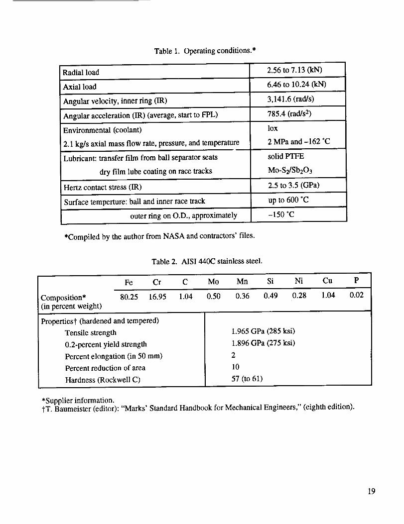
Table1. Operatingconditions.*
Radialload 2.56to 7.13 (kN)
Axial load 6.46to 10.24(kN)
Angular velocity,innerring fIR) 3,141.6 (rad/s)
Angular acceleration (1R) (average, start to FPL) 785.4 (rad/s 2)
Environmental (coolant)
2.1 kg]s axial mass flow rate, pressure, and temperature
Lubricant: transfer film from ball separator seats
dry film lube coating on race tracks
lox
2 MPa and -162 *C
solid PTFE
Mo-S2/Sb203
Hertz contact stress (IR) 2.5 to 3.5 (GPa)
Surface temperture: ball and inner race track up to 600 *C
outer ring on O.D., approximately -150 °C
*Compiled by the author from NASA and contractors' files.
Table 2. AIS1440C stainless steel.
Fe Cr C Mo Mn Si Ni Cu P
Composition* 80.25 16.95 1.04 0.50 0.36 0.49 0.28 1.04 0.02
(in percent weight)
Propertiesl" (hardened and tempered)
Tensile strength
0.2-percent yield strength
Percent elongation (in 50 mm)
Percent reduction of area
Hardness (Rockwell C)
1.965 GPa (285 ksi)
1.896 GPa (275 ksi)
2
10
57 (to 61)
*Supplier information.tT. Baumeister (editor): "Marks' Standard Handbook for Mechanical Engineers," (eighth edition).
19

Table3. SHABERTHTM convergence to target loads "M," an example.
SHABERTH TM Convergence to Target Loads "M"
FX = 8,230 (N), FR = 4,760 (N), OP.CL. = 148 (_tm), C.NGL. = 25.19
Run No.
1
2
3
4
5
6
7
8
9
10
11
12
13
14
Input Fx
8,230
8,230
8,230
8,230
8,230
8,229.99
8,229.9
8,230.1
8,230.11
8,229.99
Input Fy Output Fx
4,760
4,759.9
4,759.99
4,760.1
4,760.11
4,760
4,760
4,760
4,760
4,759.99
8,230
8,230
8,230
8,230
4,699
4,700
4,701
4,700.9
8,253
8,131
8,307
7,846
8.094
7,983
8,033
8,362
8,289
8,252
8,099
8,026
8,210
7,990
15
16
17
18
19
20
21
22
8,231
8,231
8,231
8,231
8,232
8,232
8,232
8,232
4,699
4,700
4,701
4,702
4,699
4,700
4,701
4,702
8,387
8,534
8,248
7,058
8,068
8,256
8,239
8,208
23
24
25
26
27
UNITS
8,232
8,230.8
8,230.8
8,230.8
8,230.8n_H m ,
(N)
4,700.9
4,699
4,700
4,701
8,513
7,999
8,141
8,238
4,702 8,182
(N) (N)
Output Fr
4,824
5,083
4,737
5,052
4,879
4,938
4,978
4,733
4,864
4,803
4,841
4,301
Fr.loss/OR
2,025
4,966
2,280
1,989
2,663
3,072
2,462
1,777
4,213
2,016
3,266
64,170
Fr.loss/IR
5,281
6,395
5,371
5,279
5,040
6,292
5,477
5,187
6,428
5,119
5,679
46,650
4,758
4,850
4,648
2,200
2,159
2,843
4,600
4,747
5,050
4,790
4,730
4,734
4,824
4,650
4,767
4,808
4,755
4,850
(N)
3,685
1,955
32,490
4,655
2,007
2,164
1,975
1,899
3,648
2,119II [
1,820
2,244
fw)
5,558
5,151
5,689
7,190
5,137
20,790
5,377
5,124
5,098
5,166
5,384
7,112
5,090
5,135
5,508
(w)
20

Table4. SHABERTHTM convergence to target loads "M," listing of data for quantities displayed in
figure 9.
Const. is 4,760 for lines 1 to 10, and 4,700 for lines 11 to 27
INPUT OUTPUT
Fx-8,230 Fy-Const.* delFx(%) delFr(%) Pwr.loss/OR (kW)
0
0
0
0
0
-0.01
-0.1
0.1
0.11
-0.01
0
0
0
0
1
1
1
1
2
2
2
2
2
0.8
0.8
0.8
0
-0.1
-0.01
0.1
0.11
0
0
0
0
-0.01
-1
0
1
0.9
-1
0
1
2
-1
0
1
2
0.9
-1
0
1
0.28
-1.2
0.94
--4.67
-1.65
-3
-2.39
1.6
0.72
0.27
-1.59
1.34
6.79
-0.48
6.13
2.54
3.74
4.58
-0.57
2.18
0.9
1.7
2.025
4.966
2.28
1.989
2.663
3.072
2.462
1.777
4.213
2.016
3.266
Pwr.loss/IR (kW)
5.281
6.395
5.371
5.279
5.04
6.292
5.477
5.187
6.428
5.119
5.679
0.8 2
-2.48
-0.24
2.92
1.91
3.69
0.22
-10
-1.97
0.33
0.11
-0.27
3.44
-2.81
-1.08
0.1
0.58
-9.64
-0.04
1.89
-2.35
-3.36
-0.27
6.09
0.63
-0.63
-0.5
1.34
-2.31
0.15
1.04
64.17
2.2
2.159
2.843
3.685
1.955
32.49
4.655
2.007
2.164
1.975
1.899
3.648
2.119
46.65
5.558
5.151
5.689
7.19
5.137
20.79
5.377
5.124
5.098
5.166
5.384
7.112
5.09
-0.11 1.82 5.135
1.89 2.24 5.508
21

22
i °

Table 6. Data modeled with SHABERTHrU/SINDArU.
The following data were used to compute the linear wear "I."o//= outer/inner contact
Time (min) 1 10 100
Sliding velocity (0,4) (m/s) 0.33511.159 0.361/1.083 0.414/1.152
Sliding distance (0,4) (m) 20.1/69.54 216.6/649.8 2,484/6,913
Contact area (o,6) (mm 2) 1.09910.680 1.101/0.68 0.968/0.575
Hertz pressure (o/i) (MPa) 1,959/2,502 1,966/2,554 1,725/2,136
Note: The values shown have been averaged for the 12 balls around the bearing.
23

Table 7. Wear record for flight (F) and development (D) beatings of the standard phase II
HPOTP configuration for the 1987-1993 period.
HPOTP Phase II Bearing Wear (Rocketdyne Record 1987-1993)Unit
6001R12029202976009R124216502R12221R12325R2202843062123R24402R322052224R14402R123224011R167026602R142064007R12125R16202R14202R140054406R36102R12122R12422R22026R 12324R52522R22223R12222R 14105R14406R16302R14302R12321R22324R22424R52124R24106R12025R 12121R14305R14008R39109R12425R22305R32225R34107R3
ConfigurationFFFFFFFFFFFFFFFFFFFFFFFFFFFFFFFFFFFFFFFFFFFFFFFFFFFF
Time (rain)4.24.854.94.9555.055.0577.37.58.78.88.88.88.88.99.19.19.19.19.19.19.1
10.91213.513.613.613.81414.915.817.417.417.417.817.817.818.820.420.421.521.821.821.922.323.625.726.327.327.827.8
No. 1 Wear (pro)05.15.12.52.55.12.5
12.702.52.52.505.17.65.17.6
15.22.507.6002.502.55.155.102.57.65.1002.52.50
10.202.55.12.57.65.15.12.5
10.25.15.17.60
No. 2 wear06.47.62.52.5
10.22.5
10.205.12.52.505.1
10.27.67.6
15.25.107.6005.1002.52.67.65.15.17.67.602.57.65.15.15.15.12.55.12.57.65.15.12.55.17.65.15.1
10.2
24
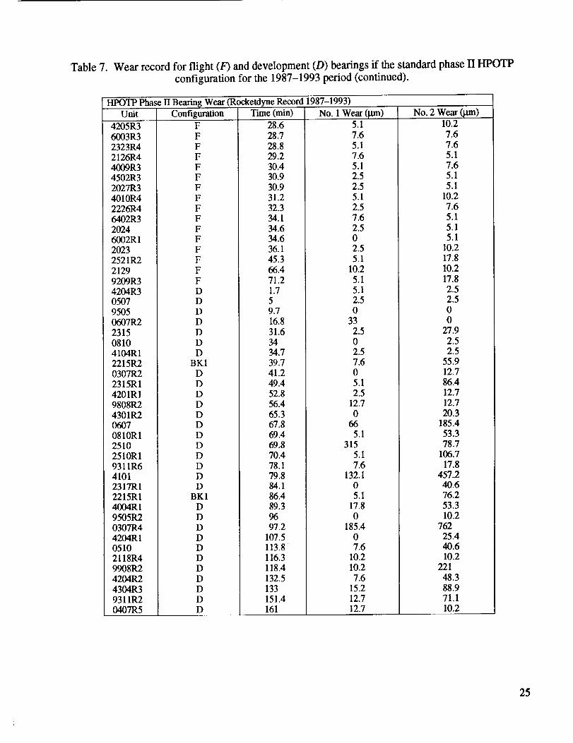
Table 7. Wear record for flight (F) and development (D) bearings if the standard phase II HPOTP
configuration for the 1987-1993 period (continued).
HPOTP Pha_ II Bearing Wear (Rocketdyne Record 1987-1993)Unit
4205R36003R32323R42126R44009R34502R32027R34010R42226R46402R320246002R120232521R221299209R34204R3050795050607R2231508104104R12215R20307R22315R14201R19808R24301R206070810R125102510R19311R641012317R12215R14004RI9505R20307R44204R 105102118R49908R2
4204R24304R39311R20407R5
Configuration
FFFFFFF
FFFFFFF
FFDDDD
DDD
BKID
DDDDDDDDDDD
BK1DDD
DDDDDDDD
Time (nan)
28.628.728.829.230.430.930.931.232.334.134.634.636.145.366.471.21.759.716.831.63434.739.741.249.452.856.465.367.869.469.870.478.179.884.186.489.39697.2
107.5113.8116.3118.4132.5133151.4161
No. 1 Wear (]am)5.17.65.17.65.12.52.55.12.57.6
2.502.55.1
10.25.1
5.12.50
332.50
2.57.605.12.5
12.7
066
5.1315
5.17.6
132.105.1
17.8
0185.4
07.6
10.210.27.6
15.212.712.7
No. 2 Wear (lain)10.2
7.67.65.17.65.1
5.110.2
7.65.15.15.1
10.217.8
10.217.82.52.5
00
27.92.52.5
55.912.786.412.712.720.3
185.453.378.7
106.7
17.8457.2
40.676.253.310.2
76225.440.610.2
221
48.388.971.110.2
25

26
0
©
o I
oo
0
o
o_
I
0o
C_
O_ 00 _ 0 _, O_ _0 _0
Z
Z
r_
° _
d ,:t _ m d u.{ o o o
0
. oo§ OOo _ _ _ _ "_ _'_ V'_ _ _ _ A
V
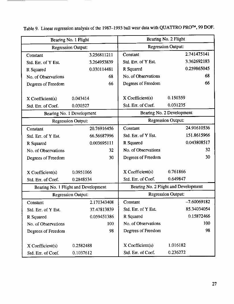
Table 9. Linear regression analysis of the 1987-1993 ball wear data with QUATrRO PRO TM, 99 DOF.
Bearing No. 1 Flight Bearing No. 2 Flight
Regression Output: Regression Output:
Constant
Std. Err. of Y Est.
R Squared
No. of Observations
Degrees of Freedom
0.043414
0.030327
X Coefficient(s)
Std. Err. of Coef.
3.256811211
3.264953839
0.030114481
68
66
Constant
Std. Err. of Y Est.
R Squared
No. of Observations
Degrees of Freedom
X Coefficient(s)
Std. Err. of Coef.
0.150359
0.031235
Bearing No. 1 Development Bearing No. 2 Development
Regression Output: Regression Output:
20.76916456
66.56687996
0.003695111
32
30
Constant
Std. Err. of Y Est.
R Squared
No. of Observations
Degrees of Freedom
0.0951066
0.2848534
X Coefficient(s)
Std. Err. of Coef.
Constant
Std. Err. of Y Est.
R Squared
No. of Observations
Degrees of Freedom
X Coefficient(s)
Std. Err. of Coef.
0.761866
0.649847
2.741475141
3.362692183
0.259865045
68
66
24.91610536
151.8615966
0.043808517
32
3O
Bearing No. 1 Flight and Development Beating No. 2 Flight and Development
Regression Output: Regression Output:
Constant 2.170343408 Constant
0.2582488
0.1037612
37.47813839
0.059451386
100
98
Std. Err. ofYEst.
R Squared
No. of Observations
Degrees of Freedom
X Coefficient(s)
Std. Err. of Coef.
1.016182
0.236272
-7.60069182
85.34034054
0.15872466
100
98
Std. Err. of Y Est.
R Squared
No. of Observations
Degrees of Freedom
X Coefficient(s)
Std. Err. of Coef.
27

Table10. Linearregressionanalysisof the 1987-1993ball weardatawith QUATIRO PROTM,
98 DOF (forced zero).
Bearing No. 1 Flight
Regression Output:
Constant
Std. Err. of Y Est.
R Squared
No. of Observations
Degrees of Freedom
X Coefficient(s)
Std. Err. of Coef.
0
3.72171779
-0.27933455
68
67
0.1589123
0.0192856
Beating No. 2 Flight
Regression Output:
Constant 0
Std. Err. of Y Est. 3.675989
R Squared 0.102125
No. of Observations 68
Degrees of Freedom 67
X Coefficient(s)
Std. Err. of Coef.
0.247582
0.019049
Beating No. 1 Development Bearing No. 2 Development
Regression Output: Regression Output:
Constant 0
Std. Err. of Y Est. 66.29116117
R Squared -0.02100425
No. of Observations 32
Degrees of Freedom 31
Constant 0
Std. Err. of Y Est. 149.9033
R Squared 0.037253
No. of Observations 32
Degrees of Freedom 31
X Coefficient(s)
Std. Err. of Coef.
0.3093513
0.1386086
Bearing No. 1 Flight and Development
Regression Output: Regression Output:
X Coefficient(s) 1.018996
Std. Err. of Coef. 0.313434
Beating No. 2 Flight and Development
Constant 0
Std. Err. ofYEst. 37.31965551
R Squared 0.05787268
No. of Observations 100
Degrees of Freedom 99
X Coefficient(s)
Std. Err. of Coef.
0.2882873
0.0723631
Constant 0
Std. Err. of Y ESt. 85.07662
R Squared 0.155443
No. of Observations 100
Degrees of Freedom 99
X Coefficient(s)
Std. Err. of Coef.
0.910985
0.164964
28

Figure 1. ASP (microfatigue) mode of wear. Ball surface of a heavily worn beating No. 352. Note manysurface cracks and wear debris. Optical microscopy (magnification: × 200top, x 1,000 bottom).
29

Figure2. ASP(microfatigue)modeof wear.Weartrackof aheavilyworn innerring or bearingNo.352.Scanningelectronmicroscopy.
30

Figure 3. Abrasion mode of wear. Wear track of a heavily worn inner ring of bearing
No. 352. Scanning electron microscopy.
31

Figure4. Weardebriscollectedfrom theNASA-MSFC's"Bearing,Seal,andMaterialsTester(BSMT)." Notenumerousthin flakesandbroken pieces of glass fibers.
Optical microscopy (× 100).
32

BEAM St:I:LllqG
Figure 5
I:VMP END MAIN ROIDR _I/RBINE END
451m_ 57ram _-4 _
BEARINGS HEARINGS
(i)(2) (3)(4)
-.][
R(I,2) R(3,4)
BALANCE PISIDN
HPOTP shaft support configuration and bearing preload arrangement. The "balance piston"
design is supposed to balance major axial loads on the shaft.
33

X0
"0 0"_
_ov_m m
Z..Q
(1).cO"_ 0
0 _
",7__.
"_.=8
0"_ Cwm
C "0mm
m
0
C)
!
c_
&0
s _
o _ .j.j
0
?O.
0k.
d
r.¢)
[-,r_
o
¢-,
8
0
: N
_ m
°_
34

1
I
,,__
,,___II _ !1
+_ _
, CO CO
__,_
35

0
"e
8
o E
, _ o
8£3_1J.S NOLLOII:I_,4
i,,_ • ,
NOLLOlU..-t 40 J-N3101:I=I300
_4
o
y "=
v _
"11'--" _':1
II il _ _&
0"_
_ _ _._
_ °
II
CL _"
36

(D>c-O
0
3"/

Z
0O3O4o0IIiIi
[_]SSO-1 '[% JON]_-I_-lla:90_O_-I
3g

w___o
0
I I I I I I I I0 0 0 0 0 0 0 0 0 0
_o
o
;>0
IT.
0
['6eo] 3qgNV IOVINOO
39
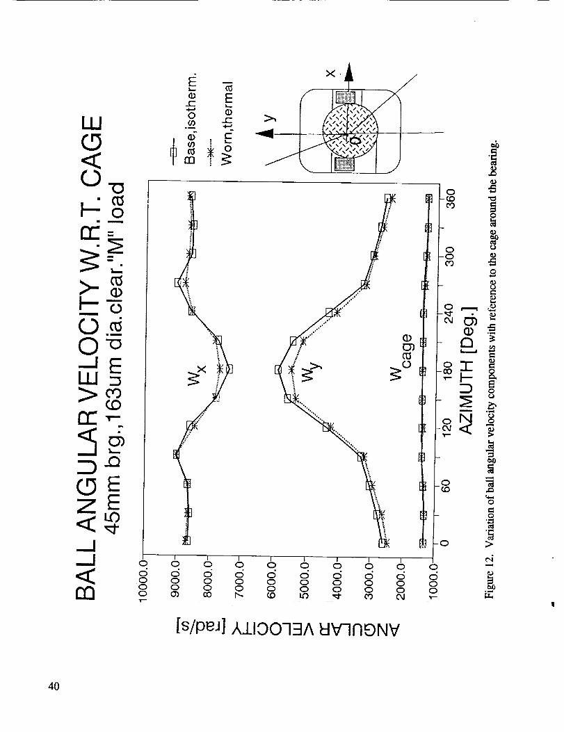
II!(D
k-:._o
o
(DE
m'-
0
0
0_.=_
0
o
I I I I I I I I0 0 0 0 0 0 0 0 0 0
0 0 0 0 0 0 0 0 0
0 0 0 0 0 0 0 0 0 00 _ _ _ _ _ _ _ _
[s/pEu] A_I_IOOq:IA t::iV7NE)NV
4O

k-0<
LuEI--E
LO
<:rn
=."-
CO rm09LU <:rr 0!-- -JcO
I I I I I
0 O 0 0 0 0d d d c_ ,:5 d0 0 0 0 0 0
0 L_ 0 _ 0
[eJ_]SSBWIS ZIWqH '[N]OVOq
0
CO
0 0-0
- £3 ._
_o.-r
o
o
o0
o
0
- "_
-0 _
0d _
41

I I I I I I I
0 0 0 0 0 0 0 0 0d d d d d d d d d0 0 0 0 0 0 0 00 _ 0 I.O 0 I._ 0 U'_
[ecllAl]SS31:llS ZII:i3H '[N]GVOq
42

W
0
-m +,---, ._
___o ,
0_. __ ..,. .: o c_
+ o+ ++ +UJx_
++ .,.,..,.
2/i ),..m i /I_, _ ......_I + +
_) 0 ........ I ° >u_ .g
I I I I Io o 0 0 0 0 0 0c5 c_ c_ c5 <:5 c_ c_ <:5o 0 0 0 0 0 0
! !
[000 I.X]}:::l/£ ' LUnl'q'8 '[N]'_-I'O
43

oO-
o.
_ffffJW/fH_//JffffJ_
_Wf__ff_fff/J_fff_
8
in
-q, .
i!,,,o-_ o
e0 m
_f/J_f/ff_SP'_
0
dI I I I I I
0 0 0 0 0 0 0d d d d d d d0 0 0 0 0 0 0I.,0 0 1.0 0 I._ 0
' _ _- _I _ CO COI I I I I I
d
[s-W/N] '73A X '$83_IcI
8I
oo
44
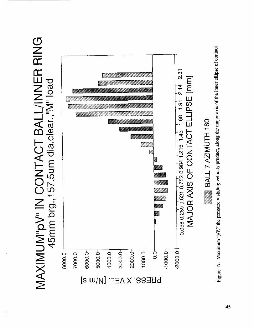
z_rr'
o.
0 _.
..Q_E
--T--T i ( i 1 T T0 0 0 0 0 0 0 0 0 0 0
d d d d d d d d d d0 0 0 0 0 0 0 0 0 00 0 0 0 0 0 0 0 0 0
[s-w/N]"73A X '853Wd
0
d
45

F-0<F-Z00
III
i
U_0EE13_
mm [s-w/N]'-13A X "SSElt:ld
46

0
0
Z o
=_
.I .Q
uo_/lllll]lllllllllll_
W_.1111_/IIIIIIII1#1 Illli_
I
1.1..0rr"
ii [s-UJlN]'73A X '883hid
47

0
Oo_rD-rr_!--'"
Q
z
m
0
!1
I I Io o o o 6 _ od d d d d d d
[s_eM] t:13MOcl
48

Z-a
oOo
0 o.
q7
0 1 I I / I / Io o o o o o o od _ d ud d Ld 6
Ii[s_eM] W3MOd
49

k-0
b-Z-oOoO-
0i
0 o
Zk_i
OOEw2OOr__LOO'--&
_Q
Ou0I
0
Ii
li:i:!:!:i:i:i:i:]:i:i:!:!:i:i:i:i:i:i:i!i!!!!!i!i!i!i
I!!!!!!!i!i!i!i!i!i!i!i!_!ii!!i!i!!!!!!!!i!!!!!!!!!!!!!!i!!!!:!:!:i:!!i!i]!!iiiii!i:i:i:i:i:i:i:i!i!i:i:i:i:i:i:i:i!i!]ii!
!:::.i:!:i:!:!:!:!:!:i:!:i:i:i:i:i:i:i:i:i:i:i:i:!:i:i:i:i:!:!:!:!:!:i:!:!:i:i:i:!:!:!:i:i:i:i:!:!:!:!:i:i:i:i:i:i:i:i:i:i:i:i:!:!:i:i:i:i:i:i:i
I:iiiiii!iiiiiiii!iii!iii!i?!:i:i:i:iiiiiiiiiiiiiiiii_iiiSi:iSiiiiiiii!iiiiiiiiiiiiiiiiiiii!_ii!!ii_i_ii!iii!iiiiiiiii
I:i:i_i!iii!!!i!]!iiiiiii!i]i!i!i!i!i!i!]]i!iii!i]i]i!iiiiiii!iiiiiiiiiiiiiiiiiiiiiiiii!iii
[i:i:i:i:i:i:i:i:i:i:i:i:i:i:iiiiiii!i!i!i!i!i!iii
I!!iii!i!i!!iiii!]i!iiiiiiiii!i!i]i]iii!!iii!iiii!
I!iii!i!iii!!!iiiiiiiii!iiiiii!iiiiii!i!i!iii!iiiiii]!iii!!iiiiiiii!iii!i!!!i!iii!!!!!iii!i
Iiiiiiii!!!iii!!!i!!iiii!!!i!ii!!i!i!i!i_i!!!!_!!!i!i!_i!!i!i!iiiiiiiii!i!iiiiiiiiiiiiiiiiii!ii!!ii!iii!i!iii!i!i!i!iiiii!ii
I ..i:i:i:i:!:i:i:i:i:i:i:i:i:i:i:i:i:i:!:]:!:!:!:!:!:!:!:!:]:i:]:]:?]:]:]:i:i:i:i:i:i:i:!!!!i!i!]!!!i!i!!!i!iii!i!i!i!i!i!iii!i!i!i!i!i_i_i_
ii!/ iii_ii!iii!iiii!!i!!iiiii!fii_:_.:ii!!!i!i!ii_i!i!ii!!iiiiiii!iii!i!iii!!!!!i!ii_!!iiiii]ii!iii!ii!!iiiii!!ii!!i!ii!!i!iii]iiiiiiiiiiiiiii
I I I I I I I I I i0 0 0 0 0 0 0 0 0 0 0
[s_eM] _3MOd
CO
E-_ E
ILl
0o
0
• ll,,q
I,)
0
e4
50

b
Oo_O-rr_
0 o.
...Q
<I:: EZ EOto
0
II
_ii!!i!iiii!i!i!i_iii_i_Si_:_i_i_i_ii_:_i_i!_i_i!!_ii_ii_:i_i_i_:_!Z:_:_l:Z_Y_:_:::!iiii!:!i!iOD
_i1i_iii_iiiii_iii!iii_iii_iii_iii_iiiiiiiiiiiii_i!iii_ii_i_!_!!_!!_i_!i_ii_iiii_!_i_!_!i_i!i_i_i_#_!;i_ii!_!iii_!iiiiiiii!iiiiii_iii_!_iii_iiiii!i_ii_ii_i!_!_i_i!_iiiiiiiii!J-"__-_
_iiiiii_ii_!_iii!_iii!iiiiiii!_ii!!!_ii!ii_i_!_!iii_i!i!_!_!i!i!_iiiii!iii_!i_iiiiiiii!i!iiiii_iiiiiiii!iiiiiiiiiiiiiii!iii_ii__ii!i_iiiiii_i!!!_i!i_!_!!ii!ii_!i!_!i_i_i_ii_i!_!iiii!i!itiii_i_i!!i!_ii!iii_|rr0"--3
[s_eM] W3MOcl
0
o
o,,,,_
51

oo
m
0 oZ_309E
09_09_0 _-
&.Q
<EZ EO_m
F__r(D
Ii
k\\\\\\\\\\\"<
k\\\\\\\\\\\\\\\\\\\\\\\\\\\'R
k\\\\\\\\\\\\\\\\\\\\\\\\\\\\\\\\\',,}
_\\\\\\\\\\\\\\\\\\\\\\\\_
k\\\\\\\\\\\\\\\\'O,
k',,\\',,,\\',_
B3
k',,\\\\\"_
K\',,\\\\\\\\\\\\\\"_
k\\\\\\\\\\\\\",,\\\\\\\\\\\",_
k\\\\",,,\_\\\\\\\\\\\\\\\\\\_
k",,\\\\\\\\\\'q
I I I I I I
0 0 0 0 0 0 0 0
r_ _ Ld _: 0d ai ,- d
[slleM] l:lEIMOd
r4)
a
III "_'
ai
--i _ e.ILl
F--,_. Q)
-_,, _ _:0 rn -d "_
m 0
d
_o ,< ..-_. _
0
d _N
52

0
b--"0
O_oO-rr_
80.OOEw2_OOLoO_
..O
0
U_
0I I I I
0 0 0 0 0 0 0
[s_eM] W3MOd
0
0
0
cO-Cxl
E-_, E-Cki
w-_ _ "_'_o,i 13_
__3 o a• '" _
-__ _
co-,- r,_ _j
cOm
rr
dz
o
0c.)
-_ 0 ._
53

I--0
I--
0 o
q7
LOi
0
LL
¢I0
0
_x\\\\\\\__-\\\\\\'x_\\\\\\\xi_ o_ E .___\\\\_\_\__\\_ w
o _._
I_\_\\\\\\\\\\\\\\\\\\N-o _ __
0 0 0 0 0 0 0 0 0
[s;_eM] l:13MOd
0
0
_5¢4
54

0
Oo
0o.
0
il
0 000 oJ o 0 0•- _ o_ _ cO 0
. . ........ N-..................... . .............................-X I-_ _o
I'_... ..X...... Fed E _o"_ .... x _ k0_ _
........_......:_...... ._ _ _ _.... ;';"_..,,,,,, I_ ._ I-
'" '._-...._ _ ....._IP_ = "_
..._ .... .,,.x _I_ 0.._..... ....×...... _.I. _>
...._'" × ._I_ _,_.._.... ...x......... ,_ ,_1-__ _,._...... ...×......... _ ,_'_,_ =o
_, ._... _ _,_ _o_ o_°
........ '._...... ' X..................._ "P_ "-" ._
0d
0 0 0 0 0 0d d d d d d
[[s_eM] U3MOa
55

56

0
i
C_
3?
0
0i
0
LL.
YI]IIIII]IIIIILtlIIt_
Y/__'_I/IZ_/I//I//I//ll/II/I//I/II//I//I//I//i//I//_/I//iI_
I_//J_/I//_VIt'/Z.'/II'/iI'/iI'_II_Z_'ZI/tI_'/II'/I//I///Z/II_Z_/V_I/IJI/J_'_
_/Z//Z//Z//Z///l///_////////////._.
I I I I 6o o o o o oc_ c_ d d c_ d d
[s_eM] _lqMOcl
57

0<_F--Z_o_
mO;
o.
O_-&
<:[_ -QZE0 E__LOI--_-0
II
_E_fEJ_ffHffH___
to
0
o
[m_eM] 1:i3MOcl
-o rr
58

F-(D
(D °
i
Zom
0,-d_
zE©E__.L r)F-_0
!1
I I ! I 6 I0 0 0 O O O
d d d d d d d
[SlmM] t:lHMOd
0
d
59

0
O- o
I
_zq
J,--<.ozE0 E_LOi_ ,,=t-0E--!.1.
I.t3041
I!:{:i:i:i:i:i:i:i:i:i:i:!:i:!:!:!:!:!:!
_i!:i:!:!:!:!8!:!:!:!:!:!:!:!:!8!:!:!:!:!:i:!:!:i:!:!:iiiiii!i!i!!!i!i!i!i!i!i!i!i!i!i!i!iii!:
I:i:::-:!:i:i:i:!:i:i:_:i:i:!:i:!:!:E:!:!:i:i:i:!:i:!:i:i:i:i:i:i:i:i:i:i:!:i:!:i:i:i:i:i:i:i:i:i:i:i:i:i:i:i:i:i:i:i:i:i:i:i:i:i:i:i:i:i:i:i:i:
[::::::::::::::::::::::_. :::::::::i:::i_:::::::::::::_:::::::::::::
.> >>>>;:>>>>:.>> >;_>',,.>.<->F>>>>> >>>>> > >>>>
E
[:i:i:}:i:i:i:i:i:i:i:!:i:i!i:i:i:i:i:!:i:i:i:!:
[6 6 6 od L4 d
[s_eM] EI3MOd
0
d
-- "r'-
-_ w
oq s_
,- ._-_ _-_ _:._
-°_-o m
-_ 0 .__
-,5 <- _ ,-
0
6O

0
Oo_mO:
n
OOELLI_
0_-
ZE0 Emtf)!_.. _-0
LL
0
0
0
[s_eM] _l]MOd
0
61

0
o
zE0 E
0E-U_
K\\\\\\_\__\\\\\\\\\x _
_\_\\\\\\\\\\\\\\\\\__
k\\\\\X
_\\\\\\\\\\\\\\\\\\\\\\\\\\\\\\\_-_ (_ __x\_\\\\\_\\\\\\\\\\\_\_\\\\\_i_ 0_
_\\\\\\\\\\\\\\\\\\\\\\\\_ w _- -_
-d
-_0
Io 6 6 6 o od _ d _ d
[s_,_,eM]N3MOd
0d
0
01,,.,-,.1
0
,4
62

O
u
O',-
ZE©E,_,_ t,O
i ....
i . _J
=,
OI I I [ I I I I
0 0 0 0 0 0 0 0 _3 0 0
_ c5 _5 d u5 d _ d _
LL U9 _ _" CO CO CW CW v- v-
[s_eM] t:13MOcl
63

0
tO-
o.
q7
Ii0b--
__\\\\\\\\\\\\\\\\\\\\__ __O
_\\\\\\\_\\\\\\\\\\\\\\\\_ _ _ o__,,_\\\\\\\\\__\\\\\\\_\_ W _
!
I I I Io o o o 6 6 od d d d d d d
[slleM] l:t3MOd
_6
64

[slleM] je_od
65

C_Z
LL
66

I--0<r.i--Z
Z
oI --
I
__! "d_
rn ErOE09,00 _
Z0
0
LL[m_eM] 1:tqMOcl
67

0
ZO_Oo
m
0
rn_<(EZLo
00_00_Oc_
_E
O_m
F-(D
Ii [slleM] kl3M0d
O
O
e0
co _ "_O
_cb
O
d
O_O
2D
m
N
Z o
O(9 "_rrLL! O!--
© g
0
o
68

0<
Z- oO_Oo
UJ = _
o2E
O_m
k-0
U_
0 00 0 0 _ CO
0 CO _ 0'_ _
o
0d
[ [s_,_,eM]_3MOd
69

Z- o
8__o-
--qZ_
LuyCOm.
'Z
0
LL
0 00 0 0 0,1 CO
0 03 _ O_ r- _--
dco
Io 8 8d _ d
OJ
[sl_eM] I::lEtMOd
70

?l

co
ii[jiiiiiiiiiiiiiiiiiiiiiii-:!'-"iiiiii
iiiiiii!iiiii!ii!inO _" _,_!iiiii
iiiiii,iii !ii!_:Iv
7- _ii.!iiiii_ ,i i ,
:""iiiiii!iiiiiii !iiiiii(iiiii __ii![ijiiiii-_LLI :::::::...................
ii!!!i! _ o
__ IllllIll I tlltilI 1 I JllIIlt J I Q
O 0 _--O _-
[Lun] IzIV_/_A77VEI
?2

73

Ill liiiii
/iio
oo
o
Iron] I:IV::IAA-i-lV_t
o
74

-r-_
0")
n
©
iii!_ii i i ii!!i!! ! i
ii!!_! i i i
d
W
0
[tun] _IV:IM 77V8
o
75
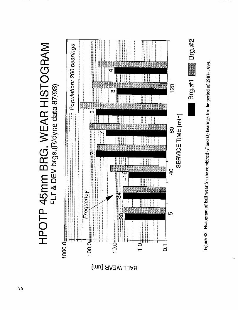
re-
0
i1'_1 "°
iiiiiii i i
iiiii!iiiii_! ! i ! i
iiii-_!'!
ct- F__w
W0
iiiii ! i i l:;:!!i ! i i iliiii i i i [[]k
L?'}
[wn] _V:IM 77V8
Od
c_n7
rn
It_
0
,,o
0
76

(5Zrr"
[.urn
o t.U_ro
q
0
!
[wn] (000 I._-Jo_ow_!G)9
77

[wn] (oooLL-Jo_ow_!a)_
°i,=_
'78

(DC9Zm
_C
WrnO_
0rnn"
oWI
Z
Cg<W
WI
Zi
d
W£30
CO E
Z_3O0
c
OOO
O
I I
tO O LO O tO O U") OO') O') CO O3 I",- I'-. CO CO
[wn] (000 I.].-Jo},oW_]C])g
O
(" o.03 o
(D NN _
-- 2-
_m
0
_ E
Z
0 _
?9

80
Or)
Zm
rr,::CILlrn
0nnrrZ_I-X0_J
LL!IF-
Z
W
W
I--
C_Zm
_J
w_
m •
Z_cO
I0 0 0 0 0 0 0 0 00 t._ 0 tO 0 t.O O tO 0
[wn] (000 I.I.-Jo)owe!(])_;
_4u,=)
dZo,0
o
"8
t4
-CO
¢-CD
o
o
,¢=,,,)
oo,,=,¢
CO
-tO

8 _
_m
m
__1LLID0
[tun] W_F_/Vk77V_
d0
81

-,,_,_.," iN i -"t_t iUNAL_. T

APPENDIX A
83

,,,-%
L o= .l-J
-,-I:' I::: I::
0 _ -,-4E-I .,-I Q) 4-1
." 0 I:: 't::l•_1 :::1
44 In
4J _
••_-I 1.400_ M -
0 _
_. ,_ m 00 _
0 Q) _ I/)
.Q ._
0 _4
0 ,.el .la
1,4 l_ I/) ¢)
¢) I_ 0 0._
0 _ .,IJ
14 I/)
__ _ .,-4
84
NOI.LOII:I:I 40 iN:llOl::h:l:lO0

85
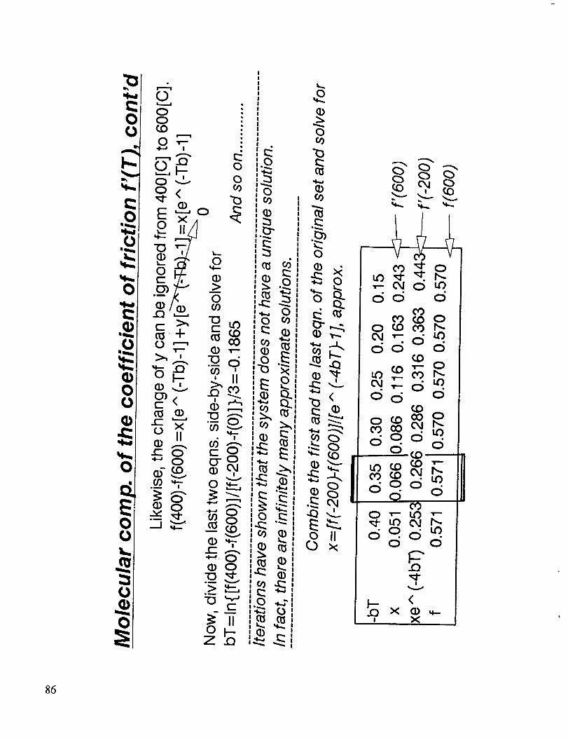
0
86

_o °
co
o
0
S'
E
o.9
!
"0
00CO
o0
0"_
d
d II _
87


APPENDIX B
PRMT,41OtNG PAGE BLANK NOT FILMED89

90

_o
91

pAGE _INTENTIONALLY BLA_i_

APPENDIX C
Ptm@ml:)#Nt PAGE BLANK NOT FILMil 93

"0_0
"ID
C:)C)COV
I--V
C)
8_
X
!1

APPENDIX D
95

SHABERTH computer printouts.
PC/SHABERTH BASED MECHANICAL MODEL
File Ref. # sinqt"M" - op.cLear. 148¢m
UNLESS OTHERWISE STATED, LINEAR DIMENSIONS ARE SPECIFIED IN MILLIMETERS, TEMPERATURES IN DEGREES CENTIGRADE,
FORCES IN NEWTONS, WEIGHTS IN KILOGRAMS, PRESSURES AND ELASTIC MODULI IN NEWTONS PER SQUARE MILLIMETER, ANGLES
AND SLOPES IN DEGREES, SURFACE ROUGHNESS IN MICRONS, SPEEDS IN REVOLUTIONS PER MINUTE, DENSITY IN GRAMS PER CUBIC
CENTIMETER, KINEMATIC VISCOSITY IN CENTISTOKES AND THERMAL CONDUCTIVITY IN WATTS PER METER-DEGREE CENTIGRADE.
SOLUTION LEVEL = 2
THE MAXIMUM NUMBER OF FIT ITERATIONS ALLOWED IS
BEARING PITCH
NUMBER DIAMETER
NUMBER OF AZIMUTH
ROLLING ANGLE
ELEMENT S OR IENTAT ION
I I2 O. 000 65. 024 O. 160 25.190 30000.CAGE DATA
BEARING CAGE TYPE CAGE POCKET RAIL-LAND RAIL-LAND RAIL-LAND
NUMBER CLEARANCE WI DT H D IAMETER CLEARANCE
I OUTER RING LAND RIDING 0.750000 2.4400 71.5518 0.229STEEL DATA
BRG.NO. INNER RING TYPE LIFE FACTOR OUTER RING TYPE LIFE FACTOR
I 440C 1.000 440C 1.000
ROLLING ELEMENT DATA
BEARING NUMBER (I) TYPE - BALL BEARING
BALL DIAMETER OUTEK RACEWAY CURVATURE INNER RACEWAY CURVATURE
11.1125 0.520 0.550
SURFACE DATA
BEARING CLA ROUGHNESS
NUMBER OUTER INNER ROLl. ElM.
1 0.01 0.01 0.01
LUBRICATION AND FRICTION DATA
5 AND THE RELATIVE ACCURACY REQUIRED IS 0.00010
DIAMETRAL CONTACT INNER RING
CLEARANCE ANGLE SPEED
RMS ASPERITY SLOPE
OUTER INNER ROLL. ELM.
2.000 2.000 2.000
BEARING I IS OPERATING DRY WITH FRICTION COEFFICIENTS OF, RACE/R.E. 0.300 CAGE/R.E. AND CAGE/RING 0.100FIT DATA AND MATERIAL PROPERTIES
CONCENTRATED MOMENT ABOUT Z
CONCENTRATED MOMENT ABOUT Y
BEARING COLD FITS (MM TIGHT) EFFECTIVE WIDTHS
NUMBER SHAFT HOUSING SHAFT INNER RING OUTER RING HOUSING
I 0.0356 -0.0660 33.8800 16.9200 16.9200 33.8800
EFFECTIVE DIAMETERS
BEARING SHAFT BEARING INNER RING OUTER RING BEARING HOUSING
NUMBER I.D. BORE AVE. O.D. AVE. I.D. O.D. O.D.
I 19.050 44.988 56.410 73.980 83.894 95.500
BEARING NUMBER (I) SHAFT INNER RING ROLL. ELEM. OUTER RING
MODULUS OF ELASTICITY 234200.0 212700.0 212700.0 212700.0
POISSONS RATIO _2900 0.2900 0.2900 0.2900
WEIGHT DENSITY 8.190 7.667 7.667 7.667
COEFF. OF THERMAL EXP. 0.00001440 0.00000929 0.00000929 0.00000929
GIVEN TEMPERATURES (C)
BRG O.RACE I.RACE BULK OIL FLNG.I FLNG.2 FLNG.3 FLNG.4 CAGE SHAFT I.RING ROLL.EL.
I -145.00 -145.00 -145.00 -145.00 -145.00 -145.00 -145.00 -145.00 -145.00 -145.00 -145.00LOADING IN THE X - Y PLANE
CONCENTRATED FORCE, FY
* 4701,0 NEWTONS
lOADING IN THE X - Z PLANE
CONCENTRATED FORCE, FZ
* O.O NEWTONS
THRUST LOAD FX = 8230.8 NEWTONS
HOUSING
193200.0
0.2900
8.190
0.00001440
OUTER RING
SPEED
O.
WEIGHT
0.020000
O.RING NSG.
-145.00 -145.00
O.O NEWTON-MM.
0.0 NEWTON-MM.
**** ERROR MESSAGE FROM THE EQUATION SOLVING ROUTINE, AT ITERATION LOOP 23 ****
**** ERROR MESSAGE FROM THE EQUATION SOLVING ROUTINE, AT ITERATION LOOP 5 ****BEARING SYSTEM OUTPUT
LINEAR (MM) AND ANGULAR (RADIANS) DEFLECTIONS REACTION FORCES (N) AND MOMENTS (MM-N)
BRG. DX DY DZ GY GZ FX FY FZ MY MZ
I 0.137 0.139 3.391E-OB'6.982E-10 5.137E'03 8.238E+03 4.703E+03 698. -2.859E+03 1.071E+03
FATIGUE LIFE (HOURS) H/SIGMA LUBE'LIFE FACTOR MATERIAL FACTOR
BRG. O. RACE I. RACE BEARING O. RACE I. RACE O. RACE I. RACE O. RACE I. RACE
I 44.9 4.96 4.60 O.O00 O.O00 1.00 1.DO 1.00 1.00
96

# LAMINA
2O
BRG. (MM-N)
I -0.215
AZIMUTH ANGULAR SPEEDS (RADIANS/SECOND)
ANGLE (DEG.) WX WY WZ TOTAL ORBITAL
0.00 -8632.202 2599.899 -0.238 9015.230 1319.887
30.00 -8599.638 2785.471 -1.258 9039.503 1320.448
60.00 -8674.904 3043.879 -4.043 9193.432 1349.152
90.00 -9011.875 3324.964 -1.455 9605.6_0 1403.525
120.00 -8615.381 4396.717 -33.596 9672.488 1428.572
150.00 -7800.085 5587.694 -2.029 9594.981 1431.754
180.00 -7397.420 5883.887 -0.004 9452.088 1424.017
210.00 -7753.875 5453.086 -0.213 9479.385 1427.156
2C0.00 -8594.141 4352.872 -0,007 9633.626 1426.810
270.00 -9028.157 3293.147 -4.998 9610.020 1403.372
300.00 -8594.641 3008.723 -0.304 9106.057 1343.553
330.00 -8586.561 2773.264 -1.030 9023.3U4 1319.486
AZIMUTH NORMAL FORCES (NEWTONS) HZ STRESS (N/MM**2)
TEMPERATURES RELEVANT TO BEARING PERFORMANCE (DEGREES CENTIGRADE)
BRG O.RACE I.RACE BULK OIL FLNG.I FLNG.2 FLNG.3 FLNG.4 CAGE SHAFT I.RING ROLL.EL. O.RING HSG.
I -145.00 "145.00 -145.00 -145.00 -145.00 -145.00 -145.00 "145.00 -145.00 -145.00 "145.00 "145.00 "145.00
FRICTIONAL HEAT GENERATION RATE (WATTS) AND FRICTION TORQUE (N-MM)
BRG. O. RACE O. FLNGS. I. RACE I. FLNGS. R.E.DRAG R.E.-CA_E CAGE'LAND TOTAL TORQUE
I 1.820E+03 0.000 5.135E+03 O.DO0 0.000 3.306E+04 0.298 4.002E+04 1,274E+04
EHD FILM THICKNESS, FILM REDUCTION FACTORS AND HEAT CONDUCTIVITY DATA FOR THE OUTER AND INNER RACEWAYS RESPECTIVELY
BRG. FILM (MICRONS) STARVATION FACTOR THERMAL FACTOR MENISCUS DIST. (MM) CONDUCTIVITY (W/DEG.C)
I 0.000 0,000 0.000 0.000 0.000 0.000 0,000 0.000 19.3 13.0
FIT PRESSURES (N/MM2) BEARING CLEARANCES (MM) SPEED GIVING ZERO FIT PRESSURE
BRG. SHAFT'COLD, OPER. HSG.-COLD, OPER. ORIGINAL CHANGE OPERATING SHAFT'INNER RING (RPM)
I 31.7 0.000 0.000 0.000 0.160 -1.178E'02 0,148 0.000
C A G E D A T A (CAGE HAS ONE DEGREE OF FREEDOM)
CAGE RAIL - RING LAND DATA CAGE SPEED DATA
TCROUE HEAT RATE SEP.FORCE ECCENTRICITY EPICYCLIC SPEED CALCULATED SPEED CALC/EPIC
(WATTS) (NEWTONS) RATIO (RAD/SEC) (RPM) (RAD/SEC) (RPM) RATIO
0.298 6.049E-02 0.100 1,388E+03 1.325E+04 1.383E+03 1.321E+04 0.997
SPEED VECTOR ANGLES (DEGREES)
CAGE/SHAFT
RATIO
0.440
SPIN TO ROLL RATIO
ANGLE (DEG.) CAGE OUTER INNER OUTER
0.00 18.946 3293.605 3001.808 2610.0GJ
30.00 478.649 2481.005 2196.738 2374.799
60.00 831.541 1149.748 839,720 1837.745
90.00 881.220 685.739 405.861 1546.929
120.00 641.034 876,801 579.027 1679.002
150.00 297.817 1367.291 1111.401 1947.023
180.00 -28.'775 1660.915 1428.258 2077.463
210.00 -338.585 1317.151 1070.337 1922.927
240.00 -658.588 907.809 625.285 1698.566
270.00 -891.785 767,984 472.945 1606.454
300.00 -821.111 1138.951 847,390 1831.974
330.00 -444.271 2483.331 2196.037 2375.540
FRICTIONAL HEAT GENERATION
ROLLING ELEMEN
INNER RACE
CONTACT AREA SEMI-MAJOR SEMI-MINOR
(MM**2) AXIS (MM) AXIS (MM)
I. 282 I .480 O. 2756
WIDTH OF LAMINUM HEAT GEN. PER LAM.
(MM) (WATTS)
O. 1420076000 O.353
O. 1420076000 3.861
O. 1420076000 9.374
O. 1420076000 15.047
O. 1420076000 19. 629
O. 1420076000 22.134
O. 1420076000 2 I.831
O. 1420076000 18.179
O. 1420076000 10.311
O. 1420076000 I .453
O. 153996300G 2. 278
O. 1539963000 20. 747
O. 1539963000 40.703
O. 1539963000 59.985
O. 1539963000 76.960
O. 1539963000 89. 250
O. 1539963000 94. 007
TAN-I(WY/WX) TAN-I(WZ/WX) OUTER INNER
163.24 -180.00 0.0049 0.1383
162.05 -179.99 0.0042 0.1601
160.66 -179.97 0.0032 0.2681
159.75 -179.99 0.0135 0.4545
152.96 -179.78 0.0037 0.5066
144.38 -179.99 -.0121 0.4450
141.50 -180.00 0.0065 0.4183
144.88 -180.00 0.0082 0.4497
153.14 -180.00 -.0019 0.5148
159.96 -179.97 -.0005 0.4674
160.71 -180.00 0.0037 0.2694
162.10 -179.99 0.0045 0.1611
LOAD RATIO QASP/QTOT CONTACT ANGLES (DEG.)
INNER OUTER INNER OUTER INNER
3513.446 0.0000 0.0000 19.8521 21.8420
3166.152 0.0000 0.0000 21.1804 24.0594
2297.826 O.OOO0 0.0000 22.7458 31.2244
1803.286 0.0000 0.0000 24.3782 41.6307
2030.043 0.0000 0.0000 31.6705 49.9271
.2522.876 0.0000 0.0000 40.5721 54.4238
2742.887 0.0000 0.0000 44.9425 55.5436
2491.414 0.0000 O.0000 41.2271 54. 1544
2082.723 0.0000 0.0000 31. 1639 50.1308
1897. 620 O.0000 0. 0000 23.3299 42. 0575
2304.801 0.0000 0.0000 22.7457 31.2234
3165.816 0.0000 0.0000 21. 1483 24.0729
IN CONTACT ELLIPSE
T NUMBER I
OUTER RACE
# LAMINA CONTACT AREA SEMI-MAJOR SEMI-MINOR
(MM**2) AXIS (HH) AXIS (MM)
19 I.893 2.119 0. 2843
WIDTH OF LAMINUM HEAT GEN. PER LAM.
(MM) (WATTS)
O. 2120541000 19.113
0.2120541000 42.428
0.2120541000 50.360
0.2120541000 47.616
O. 2120541000 38.162
O. 212054 I000 25.175
0.2120541000 10. 151
O. 2120541000 O. 785
O. 2636262000 O. 850
0. 2636262000 2. 804
O. 2636262000 0.858
O. 2189394000 0.887
0.2189394000 11.678
O. 2189394000 27. 976
0.2189394000 42.415
O. 2169394000 53. 059
O. 2189394000 56. 272
97

ling[O01
30000.0 I 0
BI 440C
65.0240 12
11.1125
0.52000 0.55000
0.0140 0.0140
-I 71.5518
0.0356000 -0.066000
19,05000 44.98850
0.1539963000 87.951 0.2189394000 _,, "Q I
O. 1539963000 67.365 O. 2189394000 /.if, , _O. 1539963000 28. 082 O.0000000000
MAXIMUM STRESS*VELOCITY IN CONTACT
BEARING NUMBER ELEMENT NUMBER STRESS VELOCITY (N/MM*S) ELEMENT NUMBER
INNER RACE
I 6 2.51198E+09 6
STRESS VELOCITY PROFILE IN CONTACT
ROLL I NG E LE MENT NUMBER 6
47.535
21.466
0.000
ELLIPSE
STRESS VELOCITY (N/MM-S)OUTER RACE
7.56120E+09
ELLIPSE
LAMINA POSITION FROM LO_JER CONTACT ANGLE EDGE OF CONTACT ELLIPSE
INNER RACE
LAMINA POSITION (MM) STRESS VELOCITY (N/MM-S)
5. 22861E" 02 -3.15725E+06
1.56858E-01 -4.9422?1_+06
2.61431E-01 -5.69051E+06
3.66003E- 01 -5.90875E+06
4.70575E- 01 -5.76138E+06
5.75147E-01 -5.33385E+06
6. 79720E- QI -4.68207E+06
7.8_292E- 01 -3.84843E+06
8.8886_E-01 -2.86894E+06
9.93436E- 01 -I.77694E+06
1.09801E+00 -6.05185E+05
I.20447E*00 6.34306E+05
1.31283E+00 1,90358E+06
1.42118E+00 3.13354E+06
I.52954E+00 4. 26739E+06
I.63790E+00 5. 23332E+06
I.74625E+00 5.93364E+06
1.85461E __0 6.22037E+06
I.96296E+00 5.82364E+06
2.07132E+00 3.98455E+06
BALL EXCURSION FROM
BALL NUMBER
1
2
3
4
5
6
7
8
9
10
11
12
OUTER
LAMINA POSITION (MM)
8.14977E-02
2.44493E-01
4.07489E-01
5.70484E-01
7.33479E-01
8.90774E-01
I. 04237E+00
I. 19396E+00
I.34555E+00
I.49715E+00
I.64874E+00
1.80034E+00
I.95193E+00
2. I0352E+00
2.25512E+00
2.40671E+00
2.56746E+00
2.73735E+00
2. 90725E+00
3. 07715E+00
BALL POCKET
POSITIVE FOR BALL LEADING THE CAGE
BALL EXCURSION (MM)
-0.0319-0.8070
-I .4020
-I. 4858
-I.0808
-0,5021
0.0485
O.57O9
1.1104
I.5036
I.3845
O. 7491
-5 00.000000000.000000000.00000000 102
0440C 0 1.00 1.00 0.00 0
0.16000 25.19 0.000
0.0140 2.00 2.00 2.00
2.4400 0.2290 0.7500 0.0200
33,88000 16.92000 16.92000 33.88000
56°41000 73.98000 83.89370 95.50000
0.2342E+O60.2127E+O60.2127E+O60.2127E+O60.1932E+06
0.290000000,290000000.290000000.290000000.29000000
8.19030 7.66700 7.66700 7.66700 8.19030
0.1440E-O40.9290E-O50.9290E-O50.9290E-O50.1440E-04
0.0000 0.0000 0.0000.300000000.100000000.000000000.000000000.00000000
I
-145.-145.-145.-145.-145.-145.-145.-145.-145.-145.-145 -145.-145. O. O.
4701.0000 0,0000 0.0000 0.0000 8230.8000
RACE
STRESS VELOCITY (N/MM-S)-8.30564E+05
o1.01133E+06
-8.37530E+05
-5.30001E+05
- 1.76990E+05
1.59373E+05
4.51482E+05
6.93652E+05
8. 73399E+03
9.82598E+05
I.01682E+06
9. 75095E+05
8.59710E+05
6.76554E+05
4.35508E+05
1.51567E+05
" 1.71812E+05
"4. 94960E+05
-7.19327E+05
"6.49424E+05
CENTER
BD1
TD2
LD1
98

******** M 0 D E L I N G U E A R I N T H E H P 0 T P 4 5 m B E A R ] N G S *********
T. J. Chase
PC/SHABERTH BASEp MECHANICAL MOOEL
Fire eef. # sinst"M"-op.ctear.123um,batt wear 2.5um.thermt
UNLESS OTHERWISE STATED, LINEAR DIMENSIONS ARE SPECIF|ED IN MILLIMETERS, TEMPERATURES IN DEGREES CENTIGRADE,
FORCES IN NEWTONS, WEIGHTS IN KILOGRAMS, PRESSURES AND ELASTIC MODULI IN NEWTONS PER SQUARE MILLIMETER, ANGLES
AND SLOPES IN DEGREES, SURFACE ROUGHNESS IN MICRONS, SPEEDS IN REVOLUTIONS PER MINUTE, DENSITY IN GRAMS PER CUBIC
CENTIMETER, KINEMATIC VISCOSITY IN CENTISTOKES AND THERMAL CONDUCTIVITY IN WATTS PER METER'DEGREE CENTIGRADE.
1
CAGE DATA
BEARING
NUMBER
SOLUTION LEVEL = 2
THE MAXIMUM NUMBER OF FIT ITERATIONS ALLOiJED IS
BEARING NUMBER OF AZIMUTH PITCHNUMBER ROLLING ANGLE DIAMETER
ELEMENTS ORIENTATION
12 O.OOO
CAGE TYPE
5 AND THE RELATIVE ACCURACY REQUIRED IS 0.00010
D]AMETRAL CONTACT INNER RING
CLEARANCE ANGLE SPEED
65.024 0.163 23.310 30000.
CAGE POCKET RAIL-LAND RAIL-LAND RAIL-LAND
CLEARANCE WIDTH DIAMETER CLEARANCE
0.750000 2.4400 71.5518 0.2291 OUTER RING LAND RIDING
STEEL DATA
BRG.NO. INNER RING TYPE LIFE FACTOR OUTER RING TYPE LIFE FACTOR
1 440C I •000 440C I. 000
ROLL I N G ELEMENT DATA
BEARING NUMBER (I) TYPE - BA.LL BEARINGBALL DIAMETER OUTER RACEWAY CURVATURE INNER RACEWAY CURVATURE
11.1100 0.519 0.549
SURFACE DATA
BEARING CLA ROUGHNESS RMS ASPERITY SLOPE
NUMBER OUTER INNER ROLL. ELM. OUTER INNER ROLL. ELM.
1 0.01 0.01 0.01 2.000 2.000 2.000
LUBRICATION AND FRICTION DATA
BEARING 1 IS OPERATING DRY WITH FRICTION COEFFICIENTS OF, RACE/R.E. 0.300 CAGE/R.E. AND CAGE/RING 0.100F ] T DATA AND MATERIAL PROPERTIES
BEARING COLD FITS
NUMBER SHAFT
I 0.0356
BEARING SHAFT
NUMBER I.D.
1 19.050
BEARING NUMBER (I)
MODULUS OF ELASTICITY
POISSONS RATIO
WEIGHT DENSITY
COEFF. OF THERMAL EXP.
GIVEN TEMPERATURES (C)
BRG O.RACE
I -133.00
LOADING IN THE X -
LOADING IN THE X -
THRUST LOAD FX =
(MM TIGHT) EFFECTIVE WIDTHSHOUSING SHAFT INNER RING OUTER RING HOUSING
-0.0660 33.8800 16.9200 16.9200 33.8800
EFFECTIVE DIAMETERS
BEARING INNER RING OUTER RING BEARING HOUSING
BORE AVE. O.D. AVE. I.D. O.D. O.D.
44.988 56.410 73.980 83.894 95.500
SHAFT INNER RING ROLL. ELEM. OUTER RING234200.0 212700.0 212700.0 212700.0
0.2900 0.2900 0.2900 0.2900
....8.190 7.667 7.667 7.667
0.00001440 0.00000929 0.00000929 0.00000929
HOUSING
193200.0
0.2900
8.190
0.00001440
[.RACE BULK OIL FLNG.1 FLNG.2
-113.00 -145.00 -145.00 -145.00
Y PLANE
CONCENTRATED FORCE, FY CONCENTRATED MOMENT ABOUT Z
4699.0 NEWTONS
Z PLANE
CONCENTRATED FORCE, FZ CONCENTRATED MOMENT ABOUT Y0.0 NEWTONS
8232.0 NEWTONS
6 ****
5 ***_
OUTER RING
SPEED
O.
WEIGHT
0.020000
FLNG.3 FLNG.4 CAGE SHAFT ].RING ROLL.EL. O.RING HSG.
-145.O0 -145.00 -120.00 -120.00 -113.00 -65.00 -133.00 -145.00
**** ERROR MESSAGE FROM THE EQUATION SOLVING ROUTINE, AT ITERATION LOOP
**** ERROR MESSAGE FROM THE EQUATION SOLVING ROUTINE, AT ITERATION LOOPBEARING SYSTEM OUTPUT
LINEAR (MM) AND ANGULAR (RADIANS) DEFLECTIONS REACTION FORCES (N) AND MOMENTS (MM-N)
BRG. DX DY DZ GY GZ FX FY FZ MY MZ
I 0.135 0.121 4.837E-08-1.227E-09 4.790E-03 8.225E+03 4.689E+03 787. -713. 37.0
FATIGUE LIFE (HOURS) H/S[GMA LUBE-LIFE FACTOR MATERIAL FACTOR
BRG. O. RACE I. RACE BEARING O. RACE I. RACE O. RACE I. RACE O. RACE I. RACE,
I 47.1 4.86 4.53 0.000 0.000 1.00 1.00 1.00 1.00
TEMPERATURES RELEVANT TO BEARING PERFORMANCE (DEGREES CENTIGRADE)
O.O NEWTON-MM.
0.0 NEWTON-MM.
99

BRG O.RACE I.RACE BULK OIL FLNG.I FLNG.2 FLNG.3 FLNG.4 CAGE SHAFT I.RING ROLL.EL. O.RING HSG.
I -133.00 "113.00 -145.00 -145.00 -145.00 "145.00 "145.00 -120.00 -120.00 "113.00 -65.00 "133.00 "145.00
FRICTIONAL HEAT GENERATION RATE (WATTS) AND FRICTION TORQUE (N-MM)
BRG. O. RACE O. FLNGS. I. RACE I. FLNGS. R.E.DRAG R.E.'CAGE CAGE-LAND TOTAL TORQUE
I 2.032E+03 0.000 5.040E+03 0.000 0.000 2.920E+04 0.295 3.628E+04 1.155E+04
EHD FILM THICKNESS, FILM REDUCTION FACTORS AND HEAT CONDUCTIVITY DATA FOR THE OUTER AND INNER RACEWAYS RESPECTIVELY
BRG. FILM (MICRONS) STARVATION FACTOR
1 O.OOO 0.000 0.000 0.000
FIT PRESSURES (N/MM2)
BRG. SHAFT-COLD, OPER. HSG.-COLD, OPER.
I 31.7 0.000 0.000 3.98
CAGE DATA
(CAGE HAS ONE DEGREE OF FREEDOM)
CAGE RAIL - RING LAND DATA CAGE SPEED DATA
TORQUE HEAT RATE SEP.FORCE ECCENTRICITY EPICYCLIC SPEED
BRG. (MM-N) (WATTS) (NEWTONS) RATIO (RAD/SEC) (RPM)
I -0.215 0.295 6.049E-02 0.100 1.374E+03 1.312E+04
R 0 L I I N G E L E M E N T 0 U T P U T FOR BEARING NUMBER I
# LAMINA
20
THERMAL FACTOR MENISCUS DIST. (MM) CONDUCTIVITY (W/DEG.C)
0.000 0.000 0.000 0.000 20.0 13.6
BEARING CLEARANCES (MM) SPEED GIVING ZERO FIT PRESSURE
ORIGINAL CHANGE OPERATING SHAFT-INNER RING (RPM)
0.163 -3.955E-02 0.123 1.891E+04
CONTACT AREA
(MM**2)
1.272
WIDTH OF LAMINUM
(MM)
0.0350268400
0.1547233000
0.1547233000
0.1547233000
0.1547233000
0.1547233000
0.1547233000
0.1547233000
0.1547233000
0.1547233000
0.1540679000
0.1540679000
0.1540679000
0.1540679000
0.1540679000
0.1540679000
AZIMUTH ANGULAR SPEEDS (RADIANS/SECOND)
ANGLE (DEG.) WX WY WZ TOTAL ORBITAL
0.00 -8668.667 2463.823 -0.247 9012.004 1317.374
30.00 -8626.444 2658.358 -0.391 9026.761 1320.550
60.00 -8592.034 2966.567 -2.456 9089.751 1338.856
90.00 -8887.136 3250.179 -2.787 9462.814 1390.403
120.00 -8547.602 4199.339 -0.712 9523.441 1409.614
150.00 -7856.861 5278.752 -I .943 9465.490 1421.355
180.00 -7580.184 5518.724 -1.007 9376.327 1413.709
210.00 -7863.542 5169.855 -0.037 9410.775 1408.188
240.00 -8542.487 4172.008 -0.019 9506.826 1411.549
270.00 -8784.269 3231.990 -0.032 9359.975 1379.887
300.00 -8600.408 2937.726 -0.184 9088.303 1338.246
330.00 -8616.725 2627.273 -0.076 9008.357 1322.079
AZIMUTH NORMAL FORCES (NEWTONS) HZ STRESS (N/MM**2)
ANGLE (DEG.) CAGE OUTER INNER OUTER INNER
0.00 6.552 3246.598 2954.212 2567.747 3484.260
30.00 401.454 2541.786 2250.867 2366.587 3182.340
60.00 717.350 1302.656 1012.278 1893.881 2438.165
90.00 776.351 830.580 535.879 1630.059 1972.357
120.O0 575.125 934.755 656.434 1695.543 2110.378
150.00 260.069 1257.401 1119.073 1871.690 2521.057
180.00 -70.049 1654.214 1409.527 2050.879 2722.624
210.00 -351.744 1357.507 1104.602 1920.099 ,2510.143
240.00 -625.493 947.718 666.098 1703.344 2120.684
270.00 -795. 160 829.768 536.463 1629.528 1973.073
300.00 -695.242 1301.609 101.2.249 1893.374 2438.142
330.00 -382.722 2542.398 2250.980 2366.777 3182.393
FRICTIONAL HEAT GENERATION IN C
ROLLING ELEMENT
INNER RACE
SEMI -MAJOR SEMI-MINOR
AXIS (MM) AXIS (MM)
I.484 O. 2728
HEAT GEN. PER LAM.
(WATTS)
0.001
0.259
4.022
10.370
16.389
20.570
21.725
18.978
11.265
1.650
2.043
19.279
38.325
56.756
73.055
84.937
CALCULATED SPEED CALC/EPIC CAGE/SHAFT
(RAD/SEC) (RPM) RATIO RATIO
1.373E+03 !.311E+04 0.999 0.437
SPEED VECTOR ANGLES (DEGREES)
TAN-I(WY/_DX)
164.13
162.87
160.95
159.91
153.84
146.10
143.94
146.68
153.97
159.80
161.14
163.04
LOAD RATIO QASP/QTOT
OUTER INNER
0.0000 0.0000
0.0000 0.0000
0.0000 0.0000
0.0000 0.0000
0.0000 0.0000
0.0000 0.0000
0.0000 0.0000
0.0000 0.0000
0.0000 0.0000
0,0000 0.0000
0.0000 0.0000
0.0000 0.0000
SPIN TO ROLL RATIO
TAN-I(WZ/WX) OUTER INNER
-180.00 0.0046 0.1316
-180.00 0.0013 0.1493
-179.98 0.0002 0.2344
-179.98 0.0063 0.3986
-180.00 0.0040 0.4482
-179.99 0.0035 0.3936
-179.99 0.0075 0.3903
-180.00 0.0044 0.4099
-180.00 0.0035 0.4520
-180.00 0.0038 0.3976
-180.00 O.On_3 0.2372
-180.00 0.0043 0.1520
CONTACT ANGLES (DEG.)
OUTER INNER
18.7921 20.7086
20.0717 22.7649
22.2564 29.1200
23.8015 38.7212
30.6984 46.3625
39.5627 50.3474
42.2563 51.9830
38.9443 50.6015
30.5323 46.4286
23.8009 38.7213
22.2701 29.1145
20.0521 22.7729
ONTACT ELLIPSE
NUMBER I
OUTER RACE
# LAMINA CONTACT AREA SEMI-MAJOR SEMI-MINOR
(MM**2) AXIS (MM) AXIS (MM)
20 I.897 2.154 O. 2803
WIDTH OF LAMINUM HEAT GEN. PER LAM.
(MM) (WATTS)
O.2074940000 I7. 949
0.2074940000 40. 192
O. 2074940000 48. 206
O. 2074940000 46.176
O. 2074940000 37.651
0.2074940000 25.518
O. 2074940000 1I.389
O. 2074940000 0.947
O. 2339875000 O. 882
O. 2339875000 4.151
O. 2339875000 4. 169
O. 2339875000 O. 893
O.2139724000 I.067
O.2139724000 12. 849
0.2139724000 28. 182
0.2139724000 41.616
1O0

0.1540679000 89.654 0.2139724000
0.1540679000 _.032 0.2139724000
0.1540679000 64.466 0.2139724000
0.1540679000 26.912 0.2139724000
MAXIMUM STRESS*VELOCITY IN CONTACT
BEARING NUMBER ELEMENT NUMBER STRESS VELOCITY (N/MM-S) ELEMENT NUMBERINNER RACE
1 8 -1.00304E+09 6
STRESS VELOCITY PROF [ LE IN CONTACTROLLING E LE MENT NUMBER 8
51.170
53.564
44.774
20.043
ELLIPSE
STRESS VELOCITY (N/MM-S)
OUTER RACE
2.30774E+09
ELLIPSE
LAMINA POSITION FROM LO_ER CONTACT ANGLE EDGE OF CONTACT ELLIPSE
INN
LAMINA POSITION5.49967E- 02
1.64990E-012.74984E-01
3.84977E-01
4.94970E- 01
6.04964 E - 01
7.14957E-01
8.24951E-01
9.34944E-01
1.04214E+00
I. 14655E+00
I.25095E+00
1.35535E+00
1.45975E+00
I.56416E+00
1.66856E+00
I.77296E+00
I.87737E+00
I.98177E+00
2. 08617E+00
ER RACE OUTER
(MM) STRESS VELOCITY (N/MM'S) LAMINA POSITION (MM)
-2.36192E+06 8.30503E-02
-3.62085E+06 2.49151E-01
-4.05333E+06 4.15251E-01
-4.04934E+06 5.81352E'01
-3.73790E+06 7.47452E-01
-3.18827E+06 9.13553E-01
-2.44769E+06 1.07965E+00
-1.55393E+06 1.24575E+00
-5.40935E+05 1,43942E+00
5.29538E+05 1.66064E+00
1.62045E+06 1.84729E+00
2.72691E+06 1.99937E+00
3.81283E+06 2.15145E+00
4.83584E+06 2.30353E*00
5.74408E+06 2,45561E+00
6.47051E+06 2.60769E+00
6.92240E+06 2.75977E+00
6.95664E+06 2.91185E+00
6.30707E+06 3.06393E+00
4.20779E+06 3.21790E+00
BALL EXCURSION FROM BALL POCKET
POSITIVE FOR BALL LEADING THE CAGE
BALL NUMBER BALL EXCURSION (1414)
1 -O,OllO
2 -0.6769
3 -1.2095
4 -I.3090
5 -0.9697
6 -0.4385
7 0.1181
8 0.5931
9 1.0546
10 1.3407
11 1.1722
12 0,6453
ling[O01
30000.0 I
BI 440C
65.0240 12
11.1100
0.51900 0.54900
0.0140 0.0140
-I 71.5518
0.0356000 -0.066000
19,05000 44.98850
bO.O0000oooo.ooooooooo.oooooooo lO2
0440C 0 1.00 1.00 0.00 0
0.16300 23.31 0.000
0.0140 2.00 2.00 2.00
2.4400 0.2290 0.7500 0.0200 I
33.88000 16.92000 16.92000 33.88000
56.41000 73.98000 83.89370 95.50000
0 -5
RACE
STRESS VELOCITY (N/MM-S)
-9.46567E+05
- I.24 I00E+06
-I.16853E+06
-9.59135E+05
-7.02065E*05
-4.47138E*05
-2. 25892E+05
-5.88608E+04
5.03953E+04
5. 04629E+04
-5.34597E+04
- 2.02892E+05
-4.01076E+05
-6.34237E*05
-8.82060E+05
-I.11455E+06
-I.28485E+06
o1.30896E+06
o9.66340E+05
-9.78820E+05
CENTER
0.2342E+O60.Z127E+O60.2127E+O60.2127E+O60.1932E+06
0.290000000.290000000.290000000.290000000.29000000
8.19030 7.66700 7.66700 7.66700 8.19030
0.1440E-O40.9290E-OSO.9290E'OSO.9290E-O50.1440E'04
0.0000 0.0000 0.0000.300000000.100000000.000000000.000000000.00000000
1
-133.-113.-145.-145.-145.-145.-145.-120.-120.-113. -65.-133.-145. 0. O.
4699.0000 0.0000 0.0000 0.0000 8232.0000
BD1
TD2
LD1
101
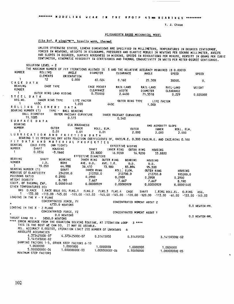
**t***** M 0 D E L I N G W E A R I N T H E H P 0 T P 6 5 mm B E A R I N G S tt***t***
T. J. Chase
PC/SHABERTH BASED MECHANICAL MODEL
File Ref. # sin<jt',M ,=, heaviiyworn, thermal
UNLESS OTHERWISE STATED, LINEAR DIMENSIONS ARE SPECIFIED IN MILLIMETERS, TEMPERATURES IN DEGREES CENTIGRADE,
FORCES IN NEWTONS, WEIGHTS IN KILOGRAMS, PRESSURES AND ELASTIC MODUL] IN NEWTONS PER SQUARE MILLIMETER, ANGLES
AND SLOPES IN DEGREES, SURFACE ROUGHNESS IN MICRONS, SPEEDS IN REVOLUTIONS PER MINUTE, DENSITY IN GRAMS PER CUBICCENTIMETER, KINEMATIC VISCOSITY IN CENT]STOKES AND THERMAL CONDUCTIVITY IN WATTS PER METER-DEGREE CENTIGRADE.
SOLUTION LEVEL = 2
THE MAXIMUM NUMBER OF FIT ITERATIONS ALLOWED IS 5 AND THE RELATIVE ACCURACY REQUIRED IS 0.00010
NUMBER ROLLING ANGLE DIAMETER CLEARANCE ANGLE SPEED SPEED
ELEMENTS ORIENTATION
I 12 O.O00 65.024 0.160 25,300 30000. O.CAGE DATA
BEARING CAGE TYPE CAGE POCKET RAIL-LAND RAIL-LAND RAIL-LAND WEIGHT
NUMBER CLEARANCE WIDTH DIAMETER CLEARANCE
I OUTER RING LAND RIDING D.750000 2.4400 71,5518 0.229 0.020000STEEL DATA
BRG.NO. INNER RING TYPE LIFE FACTOR OUTER RING TYPE LIFE FACTOR
I 440C 1.000 440C 1.000
ROllING ELEMENT DATA
BEARING NUMBER (I) TYPE - BALL BEARING
BALL DIAMETER OUTER RACEWAY CURVATURE INNER RACEWAY CURVATURE
11.1085 0.515 0.540
SURFACE DATA
BEARING CLA ROUGHNESS RMS ASPERITY SLOPE
NUMBER OUTER INNER ROLL. ELM. OUTER INNER ROLL. ELM.
I 0.01 0.01 0.01 2,000 2,000 2.000LUBRICATION AND FRICTION DATA
BEARING I IS OPERATING DRY WITH FRICTION COEFFICIENTS OF, RACE/R.E. 0.300 CAGE/R.E. AND CAGE/RING 0.100FIT DATA AND MATERIAL PROPERTIES
BEARING COLD FITS (MM TIGHT) EFFECTIVE WIDTHS
NUMBER SHAFT HOUSING SHAFT INNER RING OUTER RING HOUSING
I 0.0356 -0.0660 33.8800 i6.9200 16.9200 33.8800
EFFECTIVE DIAMETERS
BEARING SHAFT BEARING INNER RING OUTER RING BEARING HOUSING
NUMBER ].D. BORE AVE. O.D. AVE. I.D. O.D. O.D,
I 19.050 44.988 56.410 73.980 83.894 95.500
BEARING NUMBER (I) SHAFT INNER RING ROLL_ ELEM. OUTER RING
MODULUS OF ELASTICITY 234200.0 212700.0 212700.0 212700.0
POISSONS RATIO 0.2900 0.2900 0.2900 0.2900
WEIGHT DENSITY 8.190 7.667 7.667 7.667
COEFF. OF THERMAL EXP. 0.00001440 0.00000929 0.00000929 0.00000929GIVEN TEMPERATURES (C)
BRG O.RACE I.RACE BULK OIL FLNG.I FLNG.2
I -133.00 -113.00 -145.00 -145.00 -145.00
LOADING IN THE X - Y PLANE
CONCENTRATED FORCE, FY* 4735.0 NEWTONS
LOADING IN THE X - Z PLANE
CONCENTRATED FORCE, FZ* 0.0 NEWTONS
THRUST LOAD FX = 5850.0 NEWTONS
**** ERROR MESSAGE FROM THE EQUATION SOLVING ROUTINE, AT ITERATION LOOP 3 ****
THIS IS THE BEST WE CAN DO. IT MAY BE USEABLE.
REL. ACCURACY 0.000100, ITERATION LIMIT 200 NUMBER OF UNKNOWNS 6ABSOLUTE ACCURACIES
4.37342500E-07 4.37342500E-07 0.31415930 0.314159303.14159300E-02
DAMPING FACTORS I-5, OTHER STEP FACTORS 6-I0
1.0000000 1.0000000 1.0000000
5.00000000E-04 1.00000000E-03 1.00000000E-06MAXIMUM STEP FACTORS
HOUSING
193200.0
0.2900
8.190
0.00001440
FLNG.3 FLNG.4 CAGE SHAFT ].RING ROLL.EL. O.RING HSG.
-145.00 -145.00 -120.00 -120.00 -113.00 -65.00 -133.00 -145.00
CONCENTRATED MOMENT ABOUT Z
CONCENTRATED MOMENT ABOUT Y
3.14159300E-02
1.0000000 1.0000000
0.10000000 1.00000000E-05
O.O NEWTON-MM.
0.0 NEWTON-MM.
102

U.IuUUUO00
CORRECTIONS OF THE X-ES FROM SIMQ
0.13354410E-03 -0.31987950E-04 0.80727210E+03 -0.178666_0E+04 0.15089600E+00 0.18040670E+03
NUMBER OF DERIVATIVES EXPECTED FOR EACH X
-1 -1 -1 -1 -1 -1
X-VALUES0.20698840E-02 0.70372770E-02 -0.87402610E÷04 0.21413380E+04 -0.25704960E÷00 0.13153970E+04
CORRESPONDING EQ-VALUES-0.51844310E*00 0.12201910E+00 0.27360580E+03 -0.20542520E+01 0.21283190E+01 -0.17681570E÷01
**** ERROR MESSAGE FROM THE EQUATION SOLVING ROUTINE, AT ITERATION LOOP
THIS IS THE BEST WE CAN DO. IT MAY BE USEABLE,
REL. ACCURACY 0,000100° ITERATION LIMIT 200 NUMBER OF UNKNOWNS 73
ABSOLUTE ACCURACIES
4.37342500E-07 4.37342500E-07 0.31415930 0.31415930 3.14159300E-02
3.14159300E-02 4.37342500E-07 4.37342500E-07 0.31415930 0.31415930
3.14159300E-02 3.14159300E-02 4.37342500E-07 4.37342500E-07 0.31415930
0.31415930 3.14159300E-02 3.14159300E-02 4.37342500E-07 4.37342500E-07
0.31415930 0.31415930 3.14159300E-02 3.14159300E-02 4.37342500E-07
4.37342500E-07 0.31415930 0.31415930 3.14159300E-02 3.14159300E-02
4.37342500E-07 4.37342500E-07 0.31415930 0.31415930 3.14159300E-02
3.14159300E-02 4.37342500E-07 4.37342500E-07 0.31415930 0.31415930
3.14159300E-02 3.14159300E-02 4.37342500E-07 4.37342500E-07 0.31415930
0.31415930 3.14159300E-02 3.14159300E-02 4.37342500E-07 4.37342500E-07
0.31415930 0.31415930 3.14159300E-02 3.14!59300E-02 4.3T342500E-07
4.37342500E-07 0.31415930 0.31415930 3.14159300E-02 3.14159300E-02
4.37342500E-07 4.37342500E-07 0.31415930 0.31415930 3.14159300E-02
3.14159300E-02 4.37342500E-07 4.37342500E-07 0.31415930 0.31415930
3.14159300E-02 3.14159300E-02 3.85433100E-06
DAMPING FACTORS 1-5, OTHER STEP FACTORS 6-10
1.0000000 1.0000000 1.0000000 1.0000000 1.0000000
5.00000000E-04 1.00000000E-03 1.00000000E-06 0.I0000000 1.00000000E-05
MAXIMUM STEP FACTORS
0.10000000 0.10000000 0.10000000 1.0000000 1.0000000
0.10000000 0.10000000 0.10000000 0.10000000 1.0000000
1.0000000 0.10000000 0.10000000 0.10000000 0.10000000
1.0000000 1.0000000 0.10000000 0.10000000 0.10000000
0.10000000 1.0000000 1.0000000 0.10000000 0.10000000
0.10000000 0.10000000 1.0000000 1.0000000 0.10000000
0.10000000 0.10000000 0.10000000 1.0000000 1.0000000
0.10000000 0,10000000 0.10000000 0.10000000 1.0000000
1.0000000 0.10000000 0.10000000 0.10000000 0.10000000
1.0000000 1.0000000 0.10000000 0.10000000 0.10000000
0.10000000 1.0000000 1.0000000 0.10000000 0.10000000
0.10000000 0.10000000 1.0000000 1.0000000 0.10000000
0.10000000 0.10000000 0.10000000 1.0000000 1.0000000
0.10000000 0.10000000 0.10000000 0.10000000 1.0000000
1.0000000 0.10000000 0.10000000
CORRECTIONS OF THE X-ES FROM SIMQ
-0.76636580E-06
-0.I0869850E-02
0.20927650E-02
-0.80525970E-03
0.16434570E-03
0.82024600E-02
0.45051720E-03
0.I0211940E-04
0.53461450E-03
-0.53851960E-05
0.97506710E-03
0.21134460E-03
-0.I0345540E-01
NUMBER OF DERIVATIVES EXPECTED FOR EACH X
-1 -1 -1 -1
-1 -1 -1 -1
-1 -1 -1 -1
-1 -1 -1 -1
-1 -1 -1 -1
-1 -1 -1 -1
-1 -1 -1 -1
0.93931020E-07 -0.27232920E+03 -0.13733530E*04 0.56528850E-01
0.37811370E-03 -0.155127BOE+04 0.89105820E+03 -0.16906240E+03
-0.10_4190E-02 0.77037960E+04 -0.14539900E+04 -0.80215570E+02
0.58929240E-03 -0.20907520E÷05 -0.12519760E+04 0.12708710E-02
-0.41102280E-03 0.58080430E+04 0.50529380E+04 -0.71589620E÷03
-0.83580420E-02 0.78168720E+04 0.93560580E+04 0.43923380E+01
-0.59222970E-03 0.26060890E+04 -0.33576930E÷04 0.2i888820E-01
-D.17662990E-04 -0.35044770E+04 -0.37615760E+04 0.19378450E-01
-0.47624230E-03 0 35395490E+04 -0.46142740E+03 -0.45603790E+02
0.13958710E-04 -0.20480650E+04 -0.18949890E+04 -0.15138840E÷02
-0.46485430E-03 0.38711450E+04 -0.13447140E+04 -0.26822040E*02
-0.08739600E-04 0.49399040E+03 -0.14192550E+04 0.31570350E+00
-0.79875860E+01
0.16033200E*03
-0.10081070E_04
0.93362810E+03
-0.13955130E+04
0.92764920E+03
-0.66080940E÷03
-0.81257240E+02
-0.88302560E+03
0.I0552830E÷03
-0.76681150E÷03
0.77544430E+02
-1 -1 -1 -1 -1 -1
-1 -1 -1 -1 -1 -1
-1 -1 -1 -1 -1 -1
-1 -1 -1 -1 -1 -1
-1 -1 -1 -1 -1 -1
-1 -1 -1 -1 -1 -1
-1 -1 -1 -1 -1 -1
103

BEA
0.22052130E-020.21114250E-020.19576660E-020.30126_0E-020.43265050E-020.48944170E-020.43529490E-020.30205070E-020.19533220E-020.21220090E-020.22003980E-020.60444180E-04
U.lU583260E-020.68257590E-020.65373960E-020.65217200E-020.61474760E-020.54135680E-020.49892270E-020.53860460E-020.61408390E-020.65248400E-020.65321820E-020.68277'160E-02
CORRESPONDINGEQ-VALUES-0.20197850E-01-0.12476490E+01
0.40427150E-010.50650880E-01
-0.38437580E-010.15204280E+010.84490890E-010.31792340E-010.11423330E+000.56525240E-02-0.20059100E-01-0.23875220E+00
0.93154830E÷02
0.84233690E-020.80315050E+00
0.30698590E+000.11782910E+010.64270390E+00-0.I0732630E+010.37332610E+000.47985160E-010.54334360E+000.88203050E-010.50307030E+000.78179520E-01
R I N G SYSTEM OUTPLINEAR (MM) AND ANGULAR
"0.87220680E+04"0.87228570E+04"0.89030510E÷04-0.96484240E+04"0.94006230E+04"0.81719790E+04"0.75431590E+04"0.81337660E+04
"0.92556840E+04"0.95894280E÷04"0.88271430E+04-0.86918570E+04
0.21558360E+040.23615250E+040.24239490E÷040.24493530E+040.38470850E+040.54108330E+040.59782930E+040.53616890E+040.38400770E+040.24214150E+04
0.24173570E÷040.23519320E+04
-0.87544100E-01"0.11725190E+01-0.158482]0E+00-0.18157410E-02-0.14781220E+01-0.53092510E+01-0.22128720E-01-0.22061830E-01-0.40336340E+00-0.57804080E-01-0.14739850E+00-0.34284480E+00
0.13151350E+040.13161240E+040.13529900E÷040.14497730E+040.14894790E+040.14624740E+040.14481530E÷040.14621030E+040.14600580E+040.14499390E+040.13441630E+040.13175980E+04
0.27142670E+03 0.99532680E+000.35118610E+03 -0.76890810E+000.31871790E+03 -0.29010790E+000.31188300E+03 0.22525730E+010.22843800E+03 0.24625490E+010.15453420E+03 0.13009180E+010.I0805630E+03 0.98220150E+00"0.76601870E+01 0.35446380E+00"0.14858720E÷03 0-8_22_0E+00"0.25426050E÷03 0.12470050E*01
-0.21115330E*03 0.10011600E+010.40281460E+02 -0.28558710E+01
UT(RADIANS) DEFLECTIONS
0.15376160E+010.14467410E+010,14092850E+010.81138800E+000.14681620E+010.34247870E+010.40530420E÷01
-0.17445220E+01"0.18524010E÷01"0.19843660E+01"0.21340170E+01"0.33644840E+01"0.44987670E+01"0.52017740E+01
0.3934_60E+01 -0.47140970E+010.22184730E+01 -0.34397290E+010.11174560E÷01 -0.21158510E+010.99465260E+00 -0.19724600E+010.22368070E+01 -0.19150120E÷01
REACtION"FORCES'(N) AND MOMENTS(MM-N)BRG. DX DY - DZ GY , GZ FX FY FZ MY MZ
1 9.530E-02 0.130 4,345E-O8-7.662E-11 4.820E-03 5.855E+03 4.716E+03 739. -224. 490.FATIGUE LIFE (HOURS) N/SIGHA LUBE-LIFE FACTOR NATERIAL FACTOR
BRG. O. RACE I. RACE BEARING O. RACE I. RACE O. RACE I. RACE O. RACE I. RACE1 85.1 9.01 8.39 0.000 0.000 1.00 1.00 1.00 1.00
TEMPERATURESRELEVANT TO BEARING PERFORMANCE(DEGREES CENTIGRADE)BRG O.RACE I.RACE BULK OIL FLNG.1 FLNG.2 FLNG.3 FLNG.4 CAGE SHAFT I.RING ROLL.EL.
1 -133.00 -113.00 -145.00 -145.00 -145.00 -145.00 -145.00 -120.00 -120.00 -113.00 -65.00O.RING HSG.-133.00 -145.00
FRICTIONAL HEAT GENERATION RATE (WATTS) AND FRICTION TORQUE (N'V,N)BRG. O. RACE O. FLNGS. I. RACE I. FLNGS. R.E.DRAG R.E.'CAGE CAGE'LAND TOTAL TORQUE
I 1.860E+03 0.000 3.970E+03 0.000 0.000 4.567E+04 0.303 5.150E+04 1.639E+04
EHD FILM THICKNESS, FILM REDUCTION FACTORS AND HEAT CONDUCTIVITY DATA FOR THE OUTER AND INNER RACEWAYS RESPECTIVELYBRG. FILM (MICRONS) STARVATION FACTOR THERMAL FACTOR ' MENISCUS DIST. (MM) CONDUCTIVITY (I,//DEG.C)
1 0. 000 O. 000 0 •000 O. 000 O. 000 0. 000 0.000 O.000 17.7 11.1FIT PRESSURES (N/MM2) BEARING CLEARAN(:ES (NN) SPEED GIVING ZERO FIT PRESSURE
BRG. SXAFT-COLD, OPEN. HSG.-COLD, OPEN. ORIGINAL CHANGE OPERATING SHAFT-INNER RING (RPN)1 31.7 0.000 0.000 3.59 0.160 -4.222E-02 0.118 1.250E+04
CAGE DATA(CAGE HAS ONE DEGREE OF FREEDOM)
CAGE RAIL - RING LAND DATA CAGE SPEED DATA
TORQUE HEAT RATE 5EP.FORCE ECCENTRICITY EPICYCLIC SPEED CALCULATEDSPEED CALC/EPIC CAGE/SHAFTBRG. (MM-N) (WATTS) (NEWTONS) RATIO (RAD/SEC) (RPN) (RAD/SEC) (RPM) RATIO RATIO
1 -0.215 0.303 6.049E-02 0.100 1._10E+03 1.347E+04 1.407E+03 1.344E+04 0.998 0.448
R 0 L L I N G E L E M E N T 0 U T P U T FOR BEARING NUMBER1
AZIMUTH ANGULAR SPEEDS (RADIANS/SECOND) SPEED VECTORANGLES (DEGREES) SPIN TO ROLL RATIOANGLE (DEG.) WX Q/y WZ TOTAL ORBITAL TAN-I(WY/WX) TAN-I(WZ/_/X) OUTER INNER
0.00 -8722.068 2155.836 -0.088 8984.548 1315.135 166.12 -180.00 0.0023 0.115030.00 -8722.857 2361.525 -1.173 9036.871 1316.124 164.85 -179.99 0.0038 0.141260.00 -8903.051 2423.949 -0.158 9227.125 1352.990 164.77 -180.00 0.0017 0.303790.00 -9648.424 2449.353 -0.002 9954.467 1449.773 165.76 -180.00 0.0013 0.5986120.00 -9400.623 3847.085 -1.478 10157.350 1489.479 157.74 -179.99 0.0030 0.6654150.00 -8171.979 5410.833 -5.309 9800.938 1462.474 146.49 -179.96 -.0044 0.5509
180.00 -7543.159 5978.293 -0.022 9624.928 1448.153 141.60 -180.00 0.0001 0.4851210.00 -8133.766 5361.689 -0.022 9741.964 1462.103 146.61 -180.00 0.0028 0.5510240.00 -9255.684 3840.077 -0.403 10020.670 1480.058 157.47 -180.00 -.0016 0.6599270.00 -9589.428 2421.415 -0.058 9890.418 1449.939 165.83 -180.00 0.0017 0.6007
104

# LAMINA
20
.... v. ,'-,, • v.ac , lul I.,_'_', • 10,3 I(_ .0,0 - I_U.UU U.UUlb U._U21
330.00 -8691_857 235i 1932 -0.343 9004.441 1317.598 164.66 -180.00 0.0030 0.1417AZIMUTH NORMALFORCES (NEWTONS) HZ STRESS (N/MM**2) LOAD RATIO OASP/OTOT CONTACT ANGLES (DEG.)
ANGLE (DEG.) CAGE OUTER INNER OUTER INNER OUTER INNER OUTER INNER0.00 0.911 3132.797 2837.124 2432.648 3291.686 0.0000 0.0000 16.3620 18.110330.00 658.799 2202.682 1911.996 2163.146 2885.944 0.0000 0.0000 17.9042 20.658560.00 1180.900 791.278 491.268 1537,723 1834.700 O.0000 0.0000 17.8992 29.664990.00 1223.592 570.489 240.417 1378.852 1445.820 0.0000 0.0000 16.7085 43.0913120.00 776.689 701.332 389.038 1477.099 1697.421 0.0000 0.0000 26.1074 52.8317150.00 284.229 1032.480 776.641 1680.334 2137.301 0.0000 0.0000 38.6317 57.6266180.00 -59.991 1289.464 1056.275 1809,554 2368.015 0.0000 0.0000 44.4504 58.7892210.00 -402.882 1012.086 754.358 1669.i97 2116.661 0.0000 0.0000 38.9448 57.5068240.00 -860.217 692.241 383.674 1470.689 1689.583 0.0000 0.0000 26.1913 52.7992270.00 -1273.919 576.480 241.800 1383.661 1448.586 0.0000 0.0000 16.6660 43.1085
300.00 -1200.160 784.776 489.470 1533.500 1832.458 0.0000 0.0000 17.9966 29.6270330.00 -651.686 2204.747 1911.459 2163.822 2885.674 0.0000 0.0000 17.8628 20.6749
FRICTIONAL HEAT GENERATION IN CONTACT ELLIPSEROLLING ELEMENT NUMBER 1
INNER RACE OUTER RACECONTACTAREA SEMI-MAJOR SEMI-MINOR # LAMINA CONTACTAREA SEMI-MAJOR SEMI'MINOR(MM**2) AXIS (MM) AXIS (MM) (MM**2) AXIS (MM) AXIS (MM)I.21_3 I.582 O.2602 21 I.932 2.330 O.2639
_,/IDTHOF LAMINUM HEAT GEM. PER LAM. _/IDTHOF LAMINUM HEAT GEM. PER LAM.(MM) (UATTS) (1414) (WATTS)
0.1786409000 2.385 O.2249388000 2I.922O. 1786409000 0.669 0.2249388000 49.798O. 1624784000 0.567 0.2249388000 61.029O. 1624784000 4.659 0.2249388000 60.4820.1624784000 9.941 O.2249388000 52.282O.1624784000 12.763 0.2249388000 39.855O. 1624784000 12.104 O.2249388000 25.911O. 1624784000 7.017 0.2249388000 11.927O. 1624784000 1.121 O. 2249388000 2.073O. 1516899000 1.212 O. 2249388000 O. 065O. 1516899000 13.171 O. 1340418000 O. 001O. 1516899000 28.536 O.2275760000 O.068O. 1516899000 43.884 O. 2275760000 2. 202O. 1516899000 58.524 0.2275760000 12.651O. 1516899000 70.954 O. 2275760000 27.093O. 1516899000 79.300 O. 2275760000 41.617O. 1516899000 81.371 O. 2275760000 54.5980.1516899000 74.655 O.2275760000 63.189O.1516899000 56.319 0.2275760000 63.793O. 1516899000 23.194 0.2275760000 52.081O. 0000000000 O.000 O.2275760000 22.940
MAXIMUM STRESSeVELOCI TY IN CONTACT ELLIPSE'BEARING NUMBER ELEMENT NUMBER STRESS VELOCITY (N/MM-S) ELEMENTNUMBER STRESS VELOCITY (N/MM-S)
INNER RACE OUTER RACE1 6 1.12404E+10 8 "1.18030E+10
STRESS VELOCITY PROFILE IN CONTACT ELLIPSEROLLING ELE MENT NUMBER 6
LAMINA POSITION FROMLOWERCONTACTANGLE EDGE OF CONTACT ELLIPSEINNER RACE OUTER RACE
LAMINA POSITION (MM) STRESS VELOCITY (N/MM-S) LAMINA POSITION (HM) STRESS VELOCITY (N/MM-S)5.21883E- 02 -3.06789E+06 8.19662E- 02 -9.15315E+051.56565E- 01 -4.72015E+06 2.45899E- 01 -1.21799E+062.60941E -01 - 5.32757E+06 4.09831 E- 01 - 1.17004 E+063.65318E-01 -5.40168E+06 5.73763E-01 -9.88043E+054.69694E -01 -5.11248E+06 7.37696E" 01 -7.55334E+055.74071E'01 -4.55019E+06 9.01628E-01 -5.18442E+056.78447E'01 -3.77482E+06 1.06556E+00 -3.06827E+057.82824E - 01 - 2.83257E+06 1.22949E+00 - 1.39983E+ 058.87200E-01 - 1.76297E+06 1.39343E+00 "3.06322E*049.91577E" 01 -6. 02750E+05 1.58298E+00 1.46770E+041,09427E+00 5.91865E ÷05 1. 77426E+00 "3.15232E+041.19528E+ O0 1.78289E÷06 1.94163E*00 - 1.45044E +051.29630E+00 2.95171E+06 2,10901E+00 -3.19083E+051.39731E+00 4.05503E+06 2.27639E+00 -5.40509E+05I.49832E+00 5.04086E+06 2.44377E+00 -7.88970E+05I.59933E+00 5.84319E+06 2.61115E+00 -I.03355E+06
105
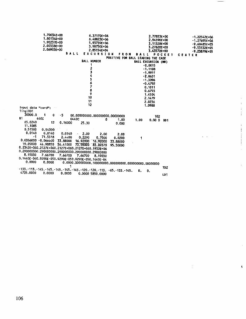
1.70034E+001.80136E+001.90237E+002.00338E+002.06903E+00
BALL
Input datalingLO01
"card"-
30000.0 1B1 440C
65.024011.10650.51500
0.0140-1
0.0356000
6.37170E+06 2.77853E+006.48823E+06 2.94590E+005.93739E+06 3.11328E+003.98750E+06 3.27828E+002.85154E+04 3.43572E+00
EXCURSION FRON BALL POCKETPOSITIVE FOR BALL LEADING THE CAGE
BALL NUNBER BALL EXCURSION (1414)1 "0.00152 "1.11083 -1.99114 -2.06315 - 1.30966 -0.47927 0.10118 0.67939 1.4504
10 2.147911 2.023612 1. O988
0 -5 00.000000000.000000000.00000000 i020440C 0 1.00 1.00 0.00 0
12 0.16000 25.30 0.000
0.54000 ::0.0140 0.0140 2.00 2.00 2.00
71.5518 2.4_00 0.2290 0.7500 0.0200-0.066000 33.88000 16.92000 16.92000 33.88000
19.05000 44.98850 56.41000 73.V8000 83.89370 95.500000.2342E+O60.2127E+O60.2127E+O60.2127E+O60.1932E+060-290000000.290000000.290000000.290000000.29000000
8.19030 7.66700 7.66700 7.66700 8.190300.1440E-O40.9290E-OSO.9290E-OSO.9290E-O50.1440E-04
0.0000 0.0000 0-0000.300000000.100000000.000000000.000000000.000000001
"133.'113.-145.-145.-145.-145.-145.-120.-120.-113. -65.-133.-145. O. 0.4735.0000 0.0000 0.0000 0.0000 5850.0000
B01
T02
L01
-1.22542E+06-1.27695E+06-9.60485E+05-9.53132E+05-9.23879E+05
CENTER
106

APPROVAL
DETAILED STUDY OF OXIDATION/WEAR MECHANISM
IN LOX TURBOPUMP BEARINGS
By T.J. Chase and J.P. McCarty
The information in this report has been reviewed for technical content. Review of any informa-
tion concerning Department of Defense or nuclear energy activities or programs has been made by the
MSFC Security Classification Officer. This report, in its entirety, has been determined to be unclassified.
J.P. MCCARTY
Director, Propulsion Laboratory
"_" u.S. GOVERNMENT PRINTING OFFOCE 1993--533-108/00002
107