Embed Size (px)
Citation preview
MELSEC iQ-F FX5 Simple Motion ModuleUser's Manual (Startup)
-FX5-40SSC-S-FX5-80SSC-S


SAFETY PRECAUTIONS(Read these precautions before use.)
Before using this product, please read this manual and the relevant manuals introduced in this manual carefully and pay full
attention to safety in order to handle the product correctly.
This manual classifies the safety precautions into two categories: [ WARNING] and [ CAUTION].
Depending on the circumstances, procedures indicated by [ CAUTION] may also cause severe injury.
It is important to follow all precautions for personal safety.
Store this manual in a safe place so that it can be read whenever necessary. Always forward it to the end user.
[DESIGN PRECAUTIONS]
WARNING Make sure to set up the following safety circuits outside the PLC to ensure safe system operation
even during external power supply problems or PLC failure. Otherwise, malfunctions may cause
serious accidents.
- Most importantly, set up the following: an emergency stop circuit, a protection circuit, an interlock
circuit for opposite movements (such as normal vs. reverse rotation), and an interlock circuit (to
prevent damage to the equipment at the upper and lower positioning limits).
- Note that when the CPU module detects an error, such as a watchdog timer error, during self-
diagnosis, all outputs are turned off. Also, when an error that cannot be detected by the CPU
module occurs in an input/output control block, output control may be disabled. External circuits
and mechanisms should be designed to ensure safe machinery operation in such a case.
- Note that the output current of the 24 V DC service power supply varies depending on the model
and the absence/presence of extension modules. If an overload occurs, the voltage automatically
drops, inputs in the PLC are disabled, and all outputs are turned off. External circuits and
mechanisms should be designed to ensure safe machinery operation in such a case.
- Note that when an error occurs in a relay, transistor or triac of an output circuit, the output might
stay on or off. For output signals that may lead to serious accidents, external circuits and
mechanisms should be designed to ensure safe machinery operation in such a case.
Construct an interlock circuit in the program so that the whole system always operates on the safe
side before executing the control (for data change) of the PLC in operation.
Read the manual thoroughly and ensure complete safety before executing other controls (for program
change, parameter change, forcible output and operation status change) of the PLC in operation.
Otherwise, the machine may be damaged and accidents may occur due to erroneous operations.
In an output circuit, when a load current exceeding the current rating or an overcurrent caused by a
load short-circuit flows for a long time, it may cause smoke and fire. To prevent this, configure an
external safety circuit, such as a fuse.
For the operating status of each station after a communication failure of the network, refer to relevant
manuals for the network. Incorrect output or malfunction may result in an accident.
To maintain the safety of the programmable controller system against unauthorized access from
external devices via the network, take appropriate measures. To maintain the safety against
unauthorized access via the Internet, take measures such as installing a firewall.
WARNING Indicates that incorrect handling may cause hazardous conditions, resulting in death or severe injury.
CAUTION Indicates that incorrect handling may cause hazardous conditions, resulting in minor or moderate injury or property damage.
1

2
[DESIGN PRECAUTIONS]
[INSTALLATION PRECAUTIONS]
CAUTION When an inductive load such as a lamp, heater, or solenoid valve is controlled, a large current
(approximately ten times greater than normal) may flow when the output is turned from off to on. Take
proper measures so that the flowing current does not exceed the value corresponding to the
maximum load specification of the resistance load.
After the CPU module is powered on or is reset, the time taken to enter the RUN status varies
depending on the system configuration, parameter settings, and/or program size.
Design circuits so that the entire system will always operate safely, regardless of this variation in time.
Simultaneously turn on and off the power supplies of the CPU module and extension modules.
If a long-time power failure or an abnormal voltage drop occurs, the PLC stops, and output is turned
off. When the power supply is restored, it will automatically restart (when the RUN/STOP/RESET
switch is on RUN side).
WARNING Make sure to cut off all phases of the power supply externally before attempting installation or wiring
work. Failure to do so may cause electric shock or damage to the product.
Use the product within the generic environment specifications described in the generic specifications
of the user's manual (Hardware) of the CPU module to use.
Never use the product in areas with excessive dust, oily smoke, conductive dusts, corrosive gas (salt
air, Cl2, H2S, SO2 or NO2), flammable gas, vibration or impacts, or expose it to high temperature,
condensation, or rain and wind.
If the product is used in such conditions, electric shock, fire, malfunctions, deterioration or damage
may occur.
[INSTALLATION PRECAUTIONS]
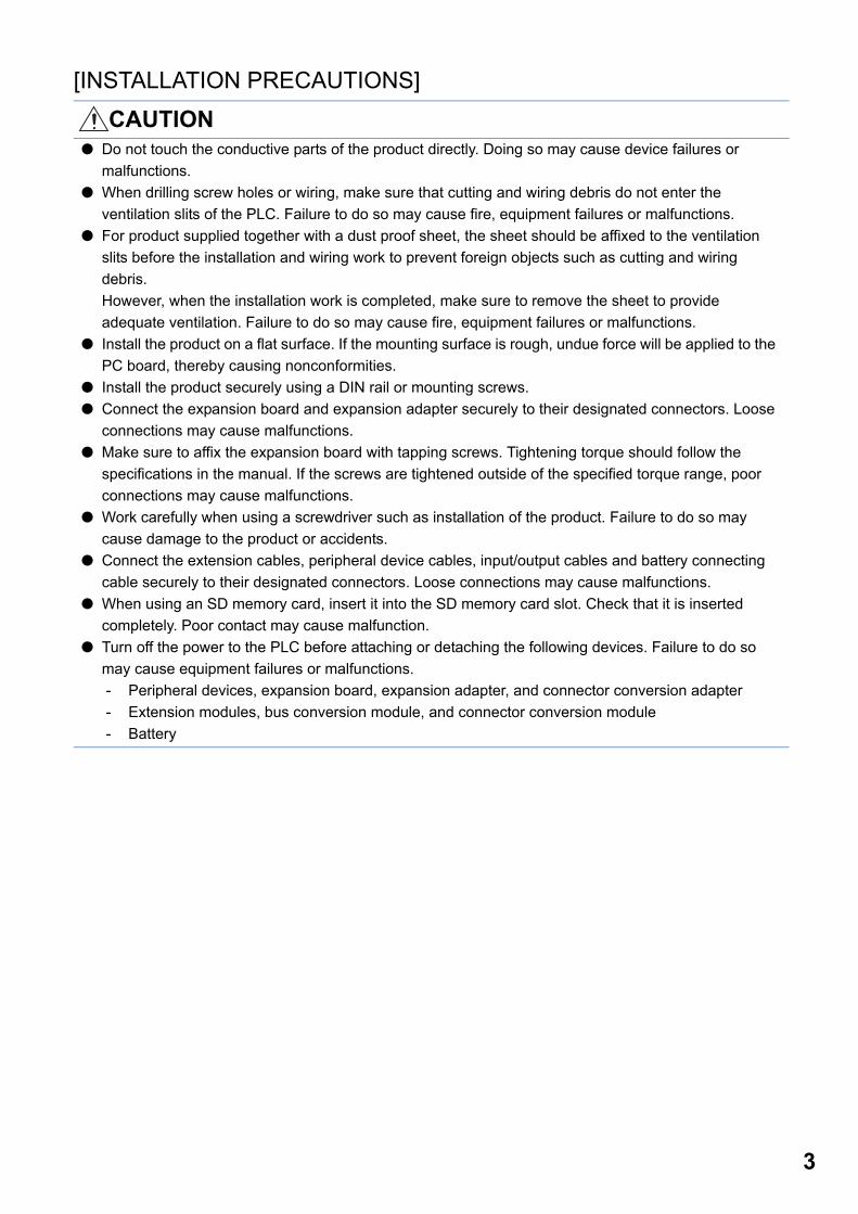
CAUTION Do not touch the conductive parts of the product directly. Doing so may cause device failures or
malfunctions.
When drilling screw holes or wiring, make sure that cutting and wiring debris do not enter the
ventilation slits of the PLC. Failure to do so may cause fire, equipment failures or malfunctions.
For product supplied together with a dust proof sheet, the sheet should be affixed to the ventilation
slits before the installation and wiring work to prevent foreign objects such as cutting and wiring
debris.
However, when the installation work is completed, make sure to remove the sheet to provide
adequate ventilation. Failure to do so may cause fire, equipment failures or malfunctions.
Install the product on a flat surface. If the mounting surface is rough, undue force will be applied to the
PC board, thereby causing nonconformities.
Install the product securely using a DIN rail or mounting screws.
Connect the expansion board and expansion adapter securely to their designated connectors. Loose
connections may cause malfunctions.
Make sure to affix the expansion board with tapping screws. Tightening torque should follow the
specifications in the manual. If the screws are tightened outside of the specified torque range, poor
connections may cause malfunctions.
Work carefully when using a screwdriver such as installation of the product. Failure to do so may
cause damage to the product or accidents.
Connect the extension cables, peripheral device cables, input/output cables and battery connecting
cable securely to their designated connectors. Loose connections may cause malfunctions.
When using an SD memory card, insert it into the SD memory card slot. Check that it is inserted
completely. Poor contact may cause malfunction.
Turn off the power to the PLC before attaching or detaching the following devices. Failure to do so
may cause equipment failures or malfunctions.
- Peripheral devices, expansion board, expansion adapter, and connector conversion adapter
- Extension modules, bus conversion module, and connector conversion module
- Battery
3
4
[WIRING PRECAUTIONS]
[WIRING PRECAUTIONS]
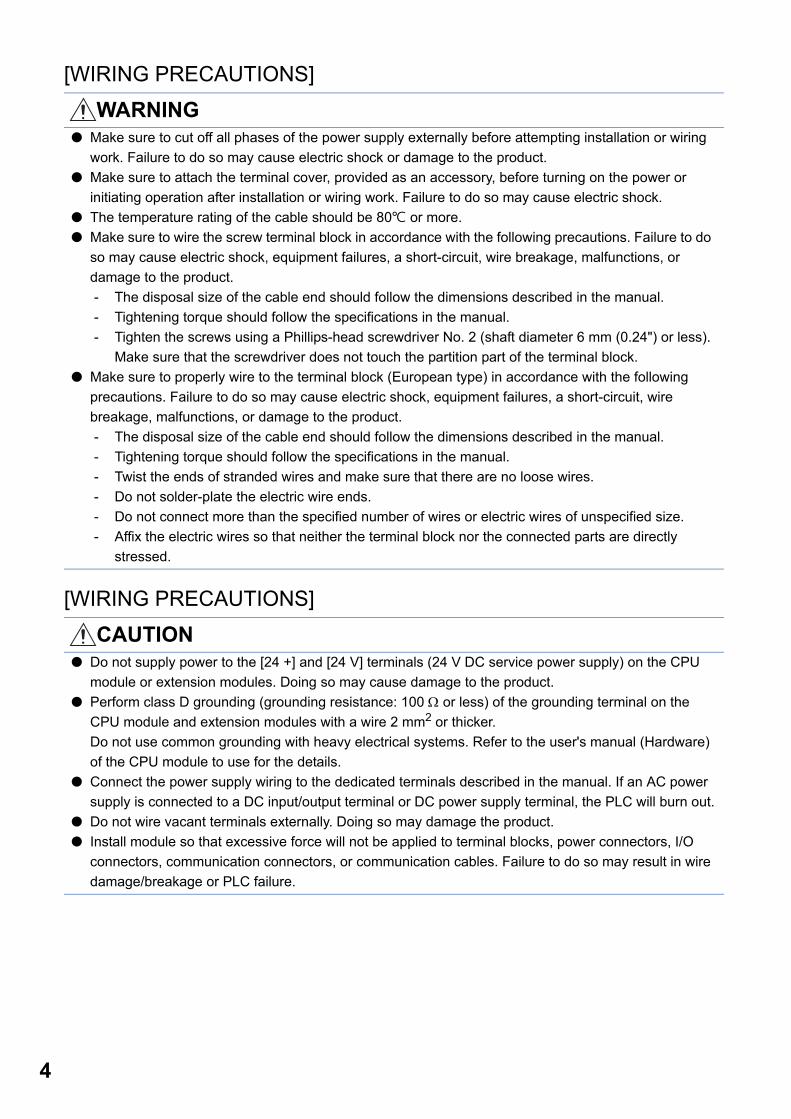
WARNING Make sure to cut off all phases of the power supply externally before attempting installation or wiring
work. Failure to do so may cause electric shock or damage to the product.
Make sure to attach the terminal cover, provided as an accessory, before turning on the power or
initiating operation after installation or wiring work. Failure to do so may cause electric shock.
The temperature rating of the cable should be 80 or more.
Make sure to wire the screw terminal block in accordance with the following precautions. Failure to do
so may cause electric shock, equipment failures, a short-circuit, wire breakage, malfunctions, or
damage to the product.
- The disposal size of the cable end should follow the dimensions described in the manual.
- Tightening torque should follow the specifications in the manual.
- Tighten the screws using a Phillips-head screwdriver No. 2 (shaft diameter 6 mm (0.24") or less).
Make sure that the screwdriver does not touch the partition part of the terminal block.
Make sure to properly wire to the terminal block (European type) in accordance with the following
precautions. Failure to do so may cause electric shock, equipment failures, a short-circuit, wire
breakage, malfunctions, or damage to the product.
- The disposal size of the cable end should follow the dimensions described in the manual.
- Tightening torque should follow the specifications in the manual.
- Twist the ends of stranded wires and make sure that there are no loose wires.
- Do not solder-plate the electric wire ends.
- Do not connect more than the specified number of wires or electric wires of unspecified size.
- Affix the electric wires so that neither the terminal block nor the connected parts are directly
stressed.
CAUTION Do not supply power to the [24 +] and [24 V] terminals (24 V DC service power supply) on the CPU
module or extension modules. Doing so may cause damage to the product.
Perform class D grounding (grounding resistance: 100 or less) of the grounding terminal on the
CPU module and extension modules with a wire 2 mm2 or thicker.
Do not use common grounding with heavy electrical systems. Refer to the user's manual (Hardware)
of the CPU module to use for the details.
Connect the power supply wiring to the dedicated terminals described in the manual. If an AC power
supply is connected to a DC input/output terminal or DC power supply terminal, the PLC will burn out.
Do not wire vacant terminals externally. Doing so may damage the product.
Install module so that excessive force will not be applied to terminal blocks, power connectors, I/O
connectors, communication connectors, or communication cables. Failure to do so may result in wire
damage/breakage or PLC failure.
[STARTUP AND MAINTENANCE PRECAUTIONS]
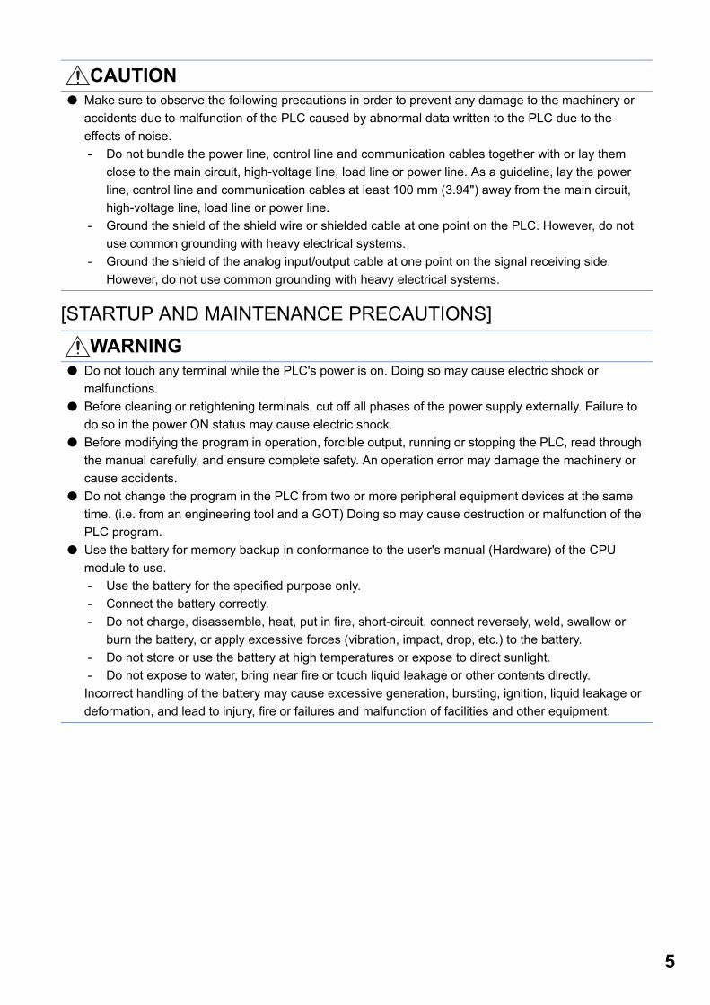
CAUTION Make sure to observe the following precautions in order to prevent any damage to the machinery or
accidents due to malfunction of the PLC caused by abnormal data written to the PLC due to the
effects of noise.
- Do not bundle the power line, control line and communication cables together with or lay them
close to the main circuit, high-voltage line, load line or power line. As a guideline, lay the power
line, control line and communication cables at least 100 mm (3.94") away from the main circuit,
high-voltage line, load line or power line.
- Ground the shield of the shield wire or shielded cable at one point on the PLC. However, do not
use common grounding with heavy electrical systems.
- Ground the shield of the analog input/output cable at one point on the signal receiving side.
However, do not use common grounding with heavy electrical systems.
WARNING Do not touch any terminal while the PLC's power is on. Doing so may cause electric shock or
malfunctions.
Before cleaning or retightening terminals, cut off all phases of the power supply externally. Failure to
do so in the power ON status may cause electric shock.
Before modifying the program in operation, forcible output, running or stopping the PLC, read through
the manual carefully, and ensure complete safety. An operation error may damage the machinery or
cause accidents.
Do not change the program in the PLC from two or more peripheral equipment devices at the same
time. (i.e. from an engineering tool and a GOT) Doing so may cause destruction or malfunction of the
PLC program.
Use the battery for memory backup in conformance to the user's manual (Hardware) of the CPU
module to use.
- Use the battery for the specified purpose only.
- Connect the battery correctly.
- Do not charge, disassemble, heat, put in fire, short-circuit, connect reversely, weld, swallow or
burn the battery, or apply excessive forces (vibration, impact, drop, etc.) to the battery.
- Do not store or use the battery at high temperatures or expose to direct sunlight.
- Do not expose to water, bring near fire or touch liquid leakage or other contents directly.
Incorrect handling of the battery may cause excessive generation, bursting, ignition, liquid leakage or
deformation, and lead to injury, fire or failures and malfunction of facilities and other equipment.
5

6
[STARTUP AND MAINTENANCE PRECAUTIONS]
[OPERATION PRECAUTIONS]
[DISPOSAL PRECAUTIONS]
CAUTION Do not disassemble or modify the PLC. Doing so may cause fire, equipment failures, or malfunctions.
For repair, contact your local Mitsubishi Electric representative.
After the first use of the SD memory card, do not insert/remove the memory card more than 500 times.
500 times or more may cause malfunction.
Turn off the power to the PLC before connecting or disconnecting any extension cable. Failure to do
so may cause equipment failures or malfunctions.
Turn off the power to the PLC before attaching or detaching the following devices. Failure to do so
may cause equipment failures or malfunctions.
- Peripheral devices, expansion board, expansion adapter, and connector conversion adapter
- Extension modules, bus conversion module, and connector conversion module
- Battery
CAUTION Construct an interlock circuit in the program so that the whole system always operates on the safe
side before executing the control (for data change) of the PLC in operation. Read the manual
thoroughly and ensure complete safety before executing other controls (for program change,
parameter change, forcible output and operation status change) of the PLC in operation. Otherwise,
the machine may be damaged and accidents may occur by erroneous operations.
CAUTION Please contact a certified electronic waste disposal company for the environmentally safe recycling
and disposal of your device.
When disposing of batteries, separate them from other waste according to local regulations. For
details on the Battery Directive in EU countries, refer to the user's manual (Hardware) of the CPU
module to use.
[TRANSPORTATION PRECAUTIONS]
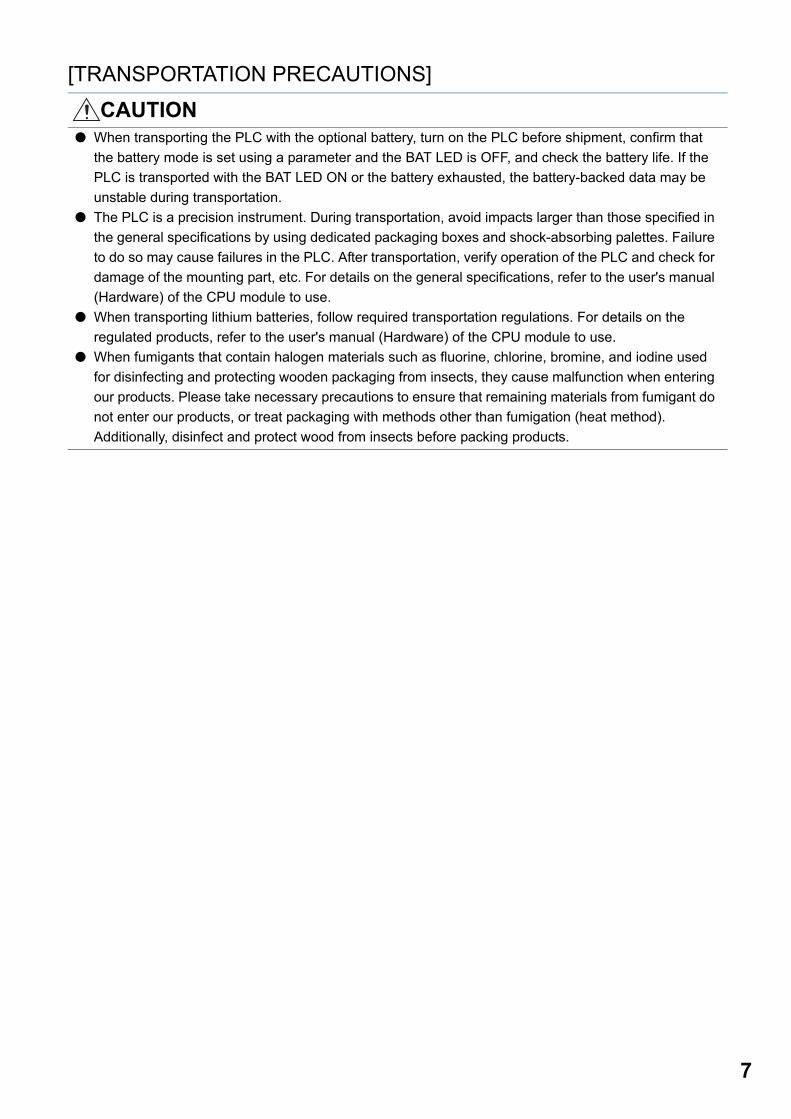
CAUTION When transporting the PLC with the optional battery, turn on the PLC before shipment, confirm that
the battery mode is set using a parameter and the BAT LED is OFF, and check the battery life. If the
PLC is transported with the BAT LED ON or the battery exhausted, the battery-backed data may be
unstable during transportation.
The PLC is a precision instrument. During transportation, avoid impacts larger than those specified in
the general specifications by using dedicated packaging boxes and shock-absorbing palettes. Failure
to do so may cause failures in the PLC. After transportation, verify operation of the PLC and check for
damage of the mounting part, etc. For details on the general specifications, refer to the user's manual
(Hardware) of the CPU module to use.
When transporting lithium batteries, follow required transportation regulations. For details on the
regulated products, refer to the user's manual (Hardware) of the CPU module to use.
When fumigants that contain halogen materials such as fluorine, chlorine, bromine, and iodine used
for disinfecting and protecting wooden packaging from insects, they cause malfunction when entering
our products. Please take necessary precautions to ensure that remaining materials from fumigant do
not enter our products, or treat packaging with methods other than fumigation (heat method).
Additionally, disinfect and protect wood from insects before packing products.
7
8
CONDITIONS OF USE FOR THE PRODUCT(1) Mitsubishi programmable controller ("the PRODUCT") shall be used in conditions;
i) where any problem, fault or failure occurring in the PRODUCT, if any, shall not lead to any major or serious accident; and ii) where the backup and fail-safe function are systematically or automatically provided outside of the PRODUCT for the case of any problem, fault or failure occurring in the PRODUCT.
(2) The PRODUCT has been designed and manufactured for the purpose of being used in general industries.MITSUBISHI SHALL HAVE NO RESPONSIBILITY OR LIABILITY (INCLUDING, BUT NOT LIMITED TO ANY AND ALL RESPONSIBILITY OR LIABILITY BASED ON CONTRACT, WARRANTY, TORT, PRODUCT LIABILITY) FOR ANY INJURY OR DEATH TO PERSONS OR LOSS OR DAMAGE TO PROPERTY CAUSED BY the PRODUCT THAT ARE OPERATED OR USED IN APPLICATION NOT INTENDED OR EXCLUDED BY INSTRUCTIONS, PRECAUTIONS, OR WARNING CONTAINED IN MITSUBISHI'S USER, INSTRUCTION AND/OR SAFETY MANUALS, TECHNICAL BULLETINS AND GUIDELINES FOR the PRODUCT. ("Prohibited Application")Prohibited Applications include, but not limited to, the use of the PRODUCT in;• Nuclear Power Plants and any other power plants operated by Power companies, and/or any other cases in which the
public could be affected if any problem or fault occurs in the PRODUCT.• Railway companies or Public service purposes, and/or any other cases in which establishment of a special quality
assurance system is required by the Purchaser or End User.• Aircraft or Aerospace, Medical applications, Train equipment, transport equipment such as Elevator and Escalator,
Incineration and Fuel devices, Vehicles, Manned transportation, Equipment for Recreation and Amusement, and Safety devices, handling of Nuclear or Hazardous Materials or Chemicals, Mining and Drilling, and/or other applications where there is a significant risk of injury to the public or property.
Notwithstanding the above, restrictions Mitsubishi may in its sole discretion, authorize use of the PRODUCT in one or more of the Prohibited Applications, provided that the usage of the PRODUCT is limited only for the specific applications agreed to by Mitsubishi and provided further that no special quality assurance or fail-safe, redundant or other safety features which exceed the general specifications of the PRODUCTs are required. For details, please contact the Mitsubishi representative in your region.
INTRODUCTIONThank you for purchasing the Mitsubishi MELSEC iQ-F series programmable controllers.
This manual describes the functions and programming of the relevant products listed below. Before using this product, please
read this manual and the relevant manuals carefully and develop familiarity with the functions and performance of the
MELSEC iQ-F series programmable controller to handle the product correctly.
When applying the program examples provided in this manual to an actual system, ensure the applicability and confirm that it
will not cause system control problems.
Please make sure that the end users read this manual.
Relevant productsFX5-40SSC-S, FX5-80SSC-S
Symbols used in this manual are shown below.
A serial No. is inserted in the "**" mark.
• [Pr.**]: Symbols indicating positioning parameter or home position return parameter items
• [Da.**]: Symbols indicating positioning data or block start data items
• [Md.**]: Symbols indicating monitor data items
• [Cd.**]: Symbols indicating control data items
Regarding use of this product • This product has been manufactured as a general-purpose part for general industries, and has not been designed or
manufactured to be incorporated in a device or system used in purposes related to human life.
• Before using the product for special purposes such as nuclear power, electric power, aerospace, medicine or passenger
movement vehicles, consult Mitsubishi Electric.
• This product has been manufactured under strict quality control. However when installing the product where major
accidents or losses could occur if the product fails, install appropriate backup or failsafe functions in the system.
Note • If in doubt at any stage during the installation of the product, always consult a professional electrical engineer who is
qualified and trained in the local and national standards. If in doubt about the operation or use, please consult the nearest
Mitsubishi Electric representative.
• Since the examples indicated by this manual, technical bulletin, catalog, etc. are used as a reference, please use it after
confirming the function and safety of the equipment and system. Mitsubishi Electric will accept no responsibility for actual
use of the product based on these illustrative examples.
• This manual content, specification etc. may be changed, without a notice, for improvement.
• The information in this manual has been carefully checked and is believed to be accurate; however, if you notice a doubtful
point, an error, etc., please contact the nearest Mitsubishi Electric representative. When doing so, please provide the
manual number given at the end of this manual.
9
10
CONTENTSSAFETY PRECAUTIONS . . . . . . . . . . . . . . . . . . . . . . . . . . . . . . . . . . . . . . . . . . . . . . . . . . . . . . . . . . . . . . . . . . . .1
CONDITIONS OF USE FOR THE PRODUCT . . . . . . . . . . . . . . . . . . . . . . . . . . . . . . . . . . . . . . . . . . . . . . . . . . . .8
INTRODUCTION. . . . . . . . . . . . . . . . . . . . . . . . . . . . . . . . . . . . . . . . . . . . . . . . . . . . . . . . . . . . . . . . . . . . . . . . . . .9
RELATED MANUALS . . . . . . . . . . . . . . . . . . . . . . . . . . . . . . . . . . . . . . . . . . . . . . . . . . . . . . . . . . . . . . . . . . . . . .12
TERMS . . . . . . . . . . . . . . . . . . . . . . . . . . . . . . . . . . . . . . . . . . . . . . . . . . . . . . . . . . . . . . . . . . . . . . . . . . . . . . . . .13
PERIPHERALS . . . . . . . . . . . . . . . . . . . . . . . . . . . . . . . . . . . . . . . . . . . . . . . . . . . . . . . . . . . . . . . . . . . . . . . . . . .14
CHAPTER 1 PART NAMES 15
1.1 LED Display Specifications . . . . . . . . . . . . . . . . . . . . . . . . . . . . . . . . . . . . . . . . . . . . . . . . . . . . . . . . . . . . . . . 16
CHAPTER 2 SPECIFICATIONS 17
2.1 General Specifications . . . . . . . . . . . . . . . . . . . . . . . . . . . . . . . . . . . . . . . . . . . . . . . . . . . . . . . . . . . . . . . . . . . 17
2.2 Power Supply Specifications . . . . . . . . . . . . . . . . . . . . . . . . . . . . . . . . . . . . . . . . . . . . . . . . . . . . . . . . . . . . . . 17
2.3 Performance Specifications . . . . . . . . . . . . . . . . . . . . . . . . . . . . . . . . . . . . . . . . . . . . . . . . . . . . . . . . . . . . . . . 17
2.4 Specifications of Interfaces with External Devices . . . . . . . . . . . . . . . . . . . . . . . . . . . . . . . . . . . . . . . . . . . . 19
Electrical specifications of input signals . . . . . . . . . . . . . . . . . . . . . . . . . . . . . . . . . . . . . . . . . . . . . . . . . . . . . . . 19
2.5 External Circuit Design . . . . . . . . . . . . . . . . . . . . . . . . . . . . . . . . . . . . . . . . . . . . . . . . . . . . . . . . . . . . . . . . . . . 21
CHAPTER 3 FUNCTION LIST 29
3.1 Control Functions . . . . . . . . . . . . . . . . . . . . . . . . . . . . . . . . . . . . . . . . . . . . . . . . . . . . . . . . . . . . . . . . . . . . . . . 29
Main functions . . . . . . . . . . . . . . . . . . . . . . . . . . . . . . . . . . . . . . . . . . . . . . . . . . . . . . . . . . . . . . . . . . . . . . . . . . . 29
Sub functions. . . . . . . . . . . . . . . . . . . . . . . . . . . . . . . . . . . . . . . . . . . . . . . . . . . . . . . . . . . . . . . . . . . . . . . . . . . . 32
Common functions. . . . . . . . . . . . . . . . . . . . . . . . . . . . . . . . . . . . . . . . . . . . . . . . . . . . . . . . . . . . . . . . . . . . . . . . 34
3.2 Combination of Main Functions and Sub Functions . . . . . . . . . . . . . . . . . . . . . . . . . . . . . . . . . . . . . . . . . . . 35
CHAPTER 4 PROCEDURES BEFORE OPERATIONS 41
CHAPTER 5 WIRING 43
5.1 Precautions for Wiring . . . . . . . . . . . . . . . . . . . . . . . . . . . . . . . . . . . . . . . . . . . . . . . . . . . . . . . . . . . . . . . . . . . 43
Power supply wiring. . . . . . . . . . . . . . . . . . . . . . . . . . . . . . . . . . . . . . . . . . . . . . . . . . . . . . . . . . . . . . . . . . . . . . . 49
5.2 External Input Connection Connector. . . . . . . . . . . . . . . . . . . . . . . . . . . . . . . . . . . . . . . . . . . . . . . . . . . . . . . 50
Signal layout for external input connection connector . . . . . . . . . . . . . . . . . . . . . . . . . . . . . . . . . . . . . . . . . . . . . 50
List of input signal details . . . . . . . . . . . . . . . . . . . . . . . . . . . . . . . . . . . . . . . . . . . . . . . . . . . . . . . . . . . . . . . . . . 51
Interface internal circuit . . . . . . . . . . . . . . . . . . . . . . . . . . . . . . . . . . . . . . . . . . . . . . . . . . . . . . . . . . . . . . . . . . . . 53
CHAPTER 6 OPERATION EXAMPLES 56
6.1 Program Examples Using Labels. . . . . . . . . . . . . . . . . . . . . . . . . . . . . . . . . . . . . . . . . . . . . . . . . . . . . . . . . . . 59
6.2 Program Examples Using Buffer Memory. . . . . . . . . . . . . . . . . . . . . . . . . . . . . . . . . . . . . . . . . . . . . . . . . . . . 64
APPENDICES 70
Appendix 1 Component List . . . . . . . . . . . . . . . . . . . . . . . . . . . . . . . . . . . . . . . . . . . . . . . . . . . . . . . . . . . . . . . . . . . . 70
Reference product . . . . . . . . . . . . . . . . . . . . . . . . . . . . . . . . . . . . . . . . . . . . . . . . . . . . . . . . . . . . . . . . . . . . . . . . 70
Appendix 2 Connection with External Devices . . . . . . . . . . . . . . . . . . . . . . . . . . . . . . . . . . . . . . . . . . . . . . . . . . . . . 76
Connector . . . . . . . . . . . . . . . . . . . . . . . . . . . . . . . . . . . . . . . . . . . . . . . . . . . . . . . . . . . . . . . . . . . . . . . . . . . . . . 76
External input signal cable. . . . . . . . . . . . . . . . . . . . . . . . . . . . . . . . . . . . . . . . . . . . . . . . . . . . . . . . . . . . . . . . . . 77
Appendix 3 How to Check the SERIAL No. . . . . . . . . . . . . . . . . . . . . . . . . . . . . . . . . . . . . . . . . . . . . . . . . . . . . . . . . 80
Appendix 4 External Dimensions . . . . . . . . . . . . . . . . . . . . . . . . . . . . . . . . . . . . . . . . . . . . . . . . . . . . . . . . . . . . . . . . 81

CO
NT
EN
TS
INDEX 82
REVISIONS. . . . . . . . . . . . . . . . . . . . . . . . . . . . . . . . . . . . . . . . . . . . . . . . . . . . . . . . . . . . . . . . . . . . . . . . . . . . . .84
WARRANTY . . . . . . . . . . . . . . . . . . . . . . . . . . . . . . . . . . . . . . . . . . . . . . . . . . . . . . . . . . . . . . . . . . . . . . . . . . . . .85
TRADEMARKS . . . . . . . . . . . . . . . . . . . . . . . . . . . . . . . . . . . . . . . . . . . . . . . . . . . . . . . . . . . . . . . . . . . . . . . . . . .86
11
12
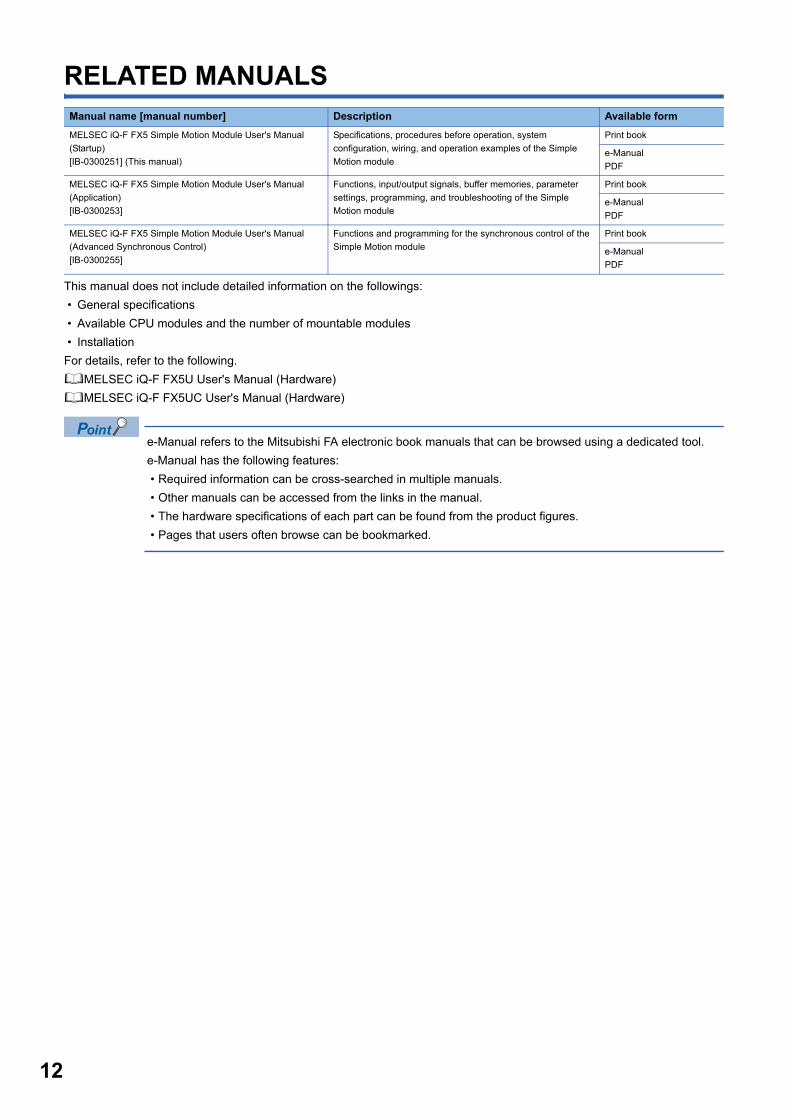
RELATED MANUALS
This manual does not include detailed information on the followings:
• General specifications
• Available CPU modules and the number of mountable modules
• Installation
For details, refer to the following.
MELSEC iQ-F FX5U User's Manual (Hardware)
MELSEC iQ-F FX5UC User's Manual (Hardware)
e-Manual refers to the Mitsubishi FA electronic book manuals that can be browsed using a dedicated tool.
e-Manual has the following features:
• Required information can be cross-searched in multiple manuals.
• Other manuals can be accessed from the links in the manual.
• The hardware specifications of each part can be found from the product figures.
• Pages that users often browse can be bookmarked.
Manual name [manual number] Description Available form
MELSEC iQ-F FX5 Simple Motion Module User's Manual
(Startup)
[IB-0300251] (This manual)
Specifications, procedures before operation, system
configuration, wiring, and operation examples of the Simple
Motion module
Print book
e-Manual
MELSEC iQ-F FX5 Simple Motion Module User's Manual
(Application)
[IB-0300253]
Functions, input/output signals, buffer memories, parameter
settings, programming, and troubleshooting of the Simple
Motion module
Print book
e-Manual
MELSEC iQ-F FX5 Simple Motion Module User's Manual
(Advanced Synchronous Control)
[IB-0300255]
Functions and programming for the synchronous control of the
Simple Motion module
Print book
e-Manual
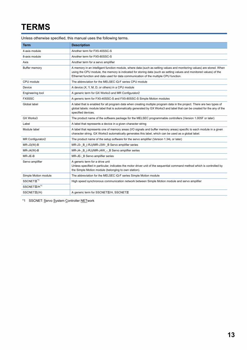
TERMSUnless otherwise specified, this manual uses the following terms.
*1 SSCNET: Servo System Controller NETwork
Term Description
4-axis module Another term for FX5-40SSC-S
8-axis module Another term for FX5-80SSC-S
Axis Another term for a servo amplifier
Buffer memory A memory in an intelligent function module, where data (such as setting values and monitoring values) are stored. When
using the CPU module, the memory is indicated for storing data (such as setting values and monitored values) of the
Ethernet function and data used for data communication of the multiple CPU function.
CPU module The abbreviation for the MELSEC iQ-F series CPU module
Device A device (X, Y, M, D, or others) in a CPU module
Engineering tool A generic term for GX Works3 and MR Configurator2
FX5SSC A generic term for FX5-40SSC-S and FX5-80SSC-S Simple Motion modules
Global label A label that is enabled for all program data when creating multiple program data in the project. There are two types of
global labels: module label that is automatically generated by GX Works3 and label that can be created for the any of the
specified devices.
GX Works3 The product name of the software package for the MELSEC programmable controllers (Version 1.005F or later)
Label A label that represents a device in a given character string
Module label A label that represents one of memory areas (I/O signals and buffer memory areas) specific to each module in a given
character string. GX Works3 automatically generates this label, which can be used as a global label.
MR Configurator2 The product name of the setup software for the servo amplifier (Version 1.34L or later)
MR-J3(W)-B MR-J3-_B_(-RJ)/MR-J3W-_B Servo amplifier series
MR-J4(W)-B MR-J4-_B_(-RJ)/MR-J4W_-_B Servo amplifier series
MR-JE-B MR-JE-_B Servo amplifier series
Servo amplifier A generic term for a drive unit
Unless specified in particular, indicates the motor driver unit of the sequential command method which is controlled by
the Simple Motion module (belonging to own station).
Simple Motion module The abbreviation for the MELSEC iQ-F series Simple Motion module
SSCNET*1 High speed synchronous communication network between Simple Motion module and servo amplifier
SSCNET/H*1
SSCNET(/H) A generic term for SSCNET/H, SSCNET
13
14
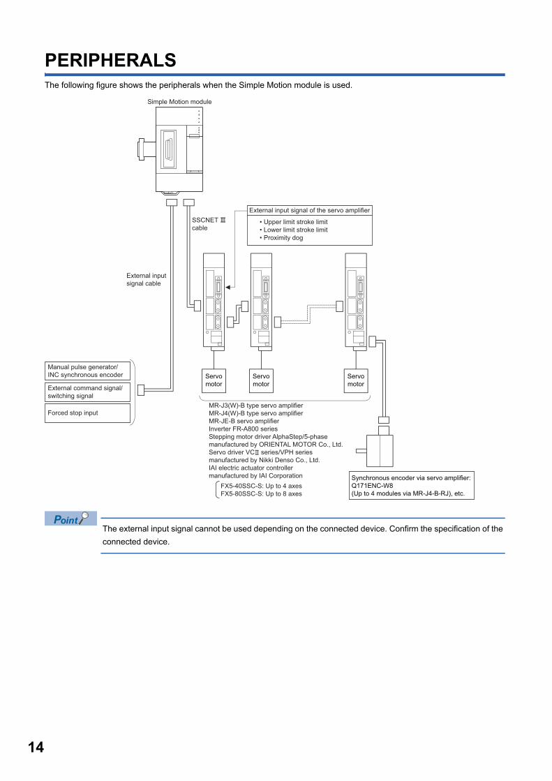
PERIPHERALSThe following figure shows the peripherals when the Simple Motion module is used.
The external input signal cannot be used depending on the connected device. Confirm the specification of the
connected device.
Simple Motion module
External command signal/switching signal
Forced stop input
External input signal of the servo amplifier
• Upper limit stroke limit• Lower limit stroke limit• Proximity dog
SSCNET cable
Manual pulse generator/INC synchronous encoder
External input signal cable
Servo motor
Servo motor
Servo motor
Synchronous encoder via servo amplifier:Q171ENC-W8(Up to 4 modules via MR-J4-B-RJ), etc.
FX5-40SSC-S: Up to 4 axesFX5-80SSC-S: Up to 8 axes
MR-J3(W)-B type servo amplifierMR-J4(W)-B type servo amplifierMR-JE-B servo amplifierInverter FR-A800 seriesStepping motor driver AlphaStep/5-phasemanufactured by ORIENTAL MOTOR Co., Ltd.Servo driver VC series/VPH seriesmanufactured by Nikki Denso Co., Ltd.IAI electric actuator controllermanufactured by IAI Corporation
1
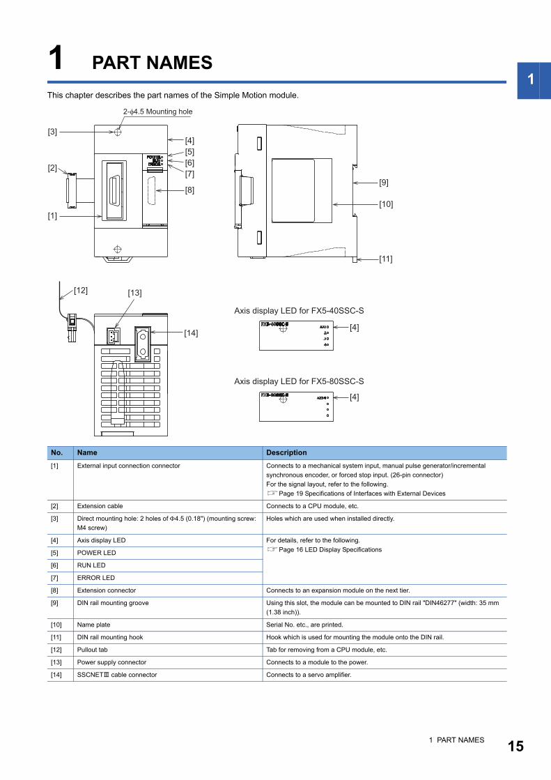
1 PART NAMESThis chapter describes the part names of the Simple Motion module.
No. Name Description
[1] External input connection connector Connects to a mechanical system input, manual pulse generator/incremental
synchronous encoder, or forced stop input. (26-pin connector)
For the signal layout, refer to the following.
Page 19 Specifications of Interfaces with External Devices
[2] Extension cable Connects to a CPU module, etc.
[3] Direct mounting hole: 2 holes of 4.5 (0.18") (mounting screw:
M4 screw)
Holes which are used when installed directly.
[4] Axis display LED For details, refer to the following.
Page 16 LED Display Specifications[5] POWER LED
[6] RUN LED
[7] ERROR LED
[8] Extension connector Connects to an expansion module on the next tier.
[9] DIN rail mounting groove Using this slot, the module can be mounted to DIN rail "DIN46277" (width: 35 mm
(1.38 inch)).
[10] Name plate Serial No. etc., are printed.
[11] DIN rail mounting hook Hook which is used for mounting the module onto the DIN rail.
[12] Pullout tab Tab for removing from a CPU module, etc.
[13] Power supply connector Connects to a module to the power.
[14] SSCNET cable connector Connects to a servo amplifier.
[1]
[3][4]
[4]
[4]
[9]
[11]
[10]
[8]
[14]
[5][6][7]
[2]
[13]
2-φ4.5 Mounting hole
[12]
Axis display LED for FX5-40SSC-S
Axis display LED for FX5-80SSC-S
1 PART NAMES 15
16
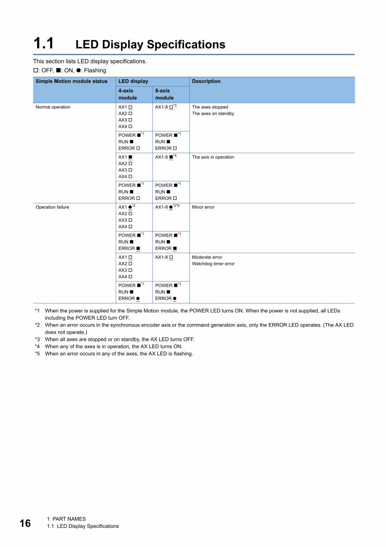
1.1 LED Display SpecificationsThis section lists LED display specifications.
: OFF, : ON, : Flashing
*1 When the power is supplied for the Simple Motion module, the POWER LED turns ON. When the power is not supplied, all LEDs including the POWER LED turn OFF.
*2 When an error occurs in the synchronous encoder axis or the command generation axis, only the ERROR LED operates. (The AX LED does not operate.)
*3 When all axes are stopped or on standby, the AX LED turns OFF.*4 When any of the axes is in operation, the AX LED turns ON.*5 When an error occurs in any of the axes, the AX LED is flashing.
Simple Motion module status LED display Description
4-axis module
8-axis module
Normal operation AX1
AX2
AX3
AX4
AX1-8 *3 The axes stopped
The axes on standby
POWER *1
RUN
ERROR
POWER *1
RUN
ERROR
AX1
AX2
AX3
AX4
AX1-8 *4 The axis in operation
POWER *1
RUN
ERROR
POWER *1
RUN
ERROR
Operation failure AX1 *2
AX2
AX3
AX4
AX1-8 *2*5 Minor error
POWER *1
RUN
ERROR
POWER *1
RUN
ERROR
AX1
AX2
AX3
AX4
AX1-8 Moderate error
Watchdog timer error
POWER *1
RUN
ERROR
POWER *1
RUN
ERROR
1 PART NAMES1.1 LED Display Specifications
2
2 SPECIFICATIONS
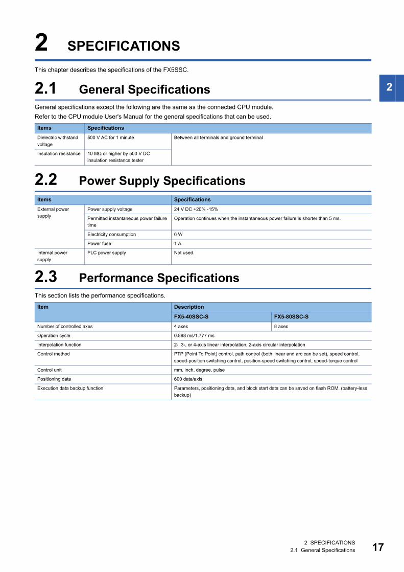
This chapter describes the specifications of the FX5SSC.
2.1 General SpecificationsGeneral specifications except the following are the same as the connected CPU module.
Refer to the CPU module User's Manual for the general specifications that can be used.
2.2 Power Supply Specifications
2.3 Performance SpecificationsThis section lists the performance specifications.
Items Specifications
Dielectric withstand
voltage
500 V AC for 1 minute Between all terminals and ground terminal
Insulation resistance 10 M or higher by 500 V DC
insulation resistance tester
Items Specifications
External power
supply
Power supply voltage 24 V DC +20% -15%
Permitted instantaneous power failure
time
Operation continues when the instantaneous power failure is shorter than 5 ms.
Electricity consumption 6 W
Power fuse 1 A
Internal power
supply
PLC power supply Not used.
Item Description
FX5-40SSC-S FX5-80SSC-S
Number of controlled axes 4 axes 8 axes
Operation cycle 0.888 ms/1.777 ms
Interpolation function 2-, 3-, or 4-axis linear interpolation, 2-axis circular interpolation
Control method PTP (Point To Point) control, path control (both linear and arc can be set), speed control,
speed-position switching control, position-speed switching control, speed-torque control
Control unit mm, inch, degree, pulse
Positioning data 600 data/axis
Execution data backup function Parameters, positioning data, and block start data can be saved on flash ROM. (battery-less
backup)
2 SPECIFICATIONS2.1 General Specifications 17

18
*1 The speed-position switching control (ABS mode) can be used only when the control unit is "degree".*2 When "Speed control 10 times multiplier setting for degree axis function" is valid, the setting range is 0.01 to 20000000.00 (degree/min).*3 Time from accepting the positioning start signal until BUSY signal turns ON.*4 AWG24 (0.2 mm2) is recommended.
Positioning Positioning system PTP control: Incremental system/absolute system
Speed-position switching control: Incremental system/absolute system
Position-speed switching control: Incremental system
Path control: Incremental system/absolute system
Positioning range In absolute system
• -214748364.8 to 214748364.7 (m)
• -21474.83648 to 21474.83647 (inch)
• 0 to 359.99999 (degree)
• -2147483648 to 2147483647 (pulse)
In incremental system
• -214748364.8 to 214748364.7 (m)
• -21474.83648 to 21474.83647 (inch)
• -21474.83648 to 21474.83647 (degree)
• -2147483648 to 2147483647 (pulse)
In speed-position switching control (INC mode)/position-speed switching control
• 0 to 214748364.7 (m)
• 0 to 21474.83647 (inch)
• 0 to 21474.83647 (degree)
• 0 to 2147483647 (pulse)
In speed-position switching control (ABS mode)*1
0 to 359.99999 (degree)
Speed command 0.01 to 20000000.00 (mm/min)
0.001 to 2000000.000 (inch/min)
0.001 to 2000000.000 (degree/min)*2
1 to 1000000000 (pulse/s)
Acceleration/deceleration process Trapezoidal acceleration/deceleration, S-curve acceleration/deceleration
Acceleration/deceleration time 1 to 8388608 (ms) (Four patterns can be set for each of acceleration time and deceleration
time.)
Rapid stop deceleration time 1 to 8388608 (ms)
Starting time*3 1.777 ms
External wiring connection system 26-pin connector
Applicable wire size*4 AWG30 to 24 (0.05 to 0.2 mm2) *4
External input wiring connector LD77MHIOCON
Manual pulse generator/Incremental
synchronous encoder input maximum
frequency
Differential-output
type
Up to 1 Mpulses/s
Open-collector
type
Up to 200 kpulses/s
Manual pulse generator 1 pulse input magnification 1 to 10000 times
Flash ROM write count Max. 100000 times
Number of occupied I/O points 8 points
Mass Approx. 0.3 kg
Item Description
FX5-40SSC-S FX5-80SSC-S
2 SPECIFICATIONS2.3 Performance Specifications
2
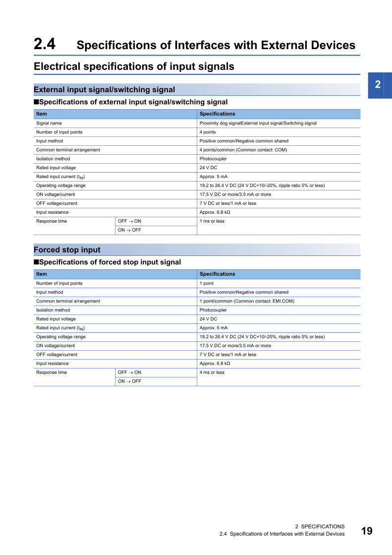
2.4 Specifications of Interfaces with External Devices
Electrical specifications of input signals
External input signal/switching signal
Specifications of external input signal/switching signal
Forced stop input
Specifications of forced stop input signal
Item Specifications
Signal name Proximity dog signalExternal input signal/Switching signal
Number of input points 4 points
Input method Positive common/Negative common shared
Common terminal arrangement 4 points/common (Common contact: COM)
Isolation method Photocoupler
Rated input voltage 24 V DC
Rated input current (IIN) Approx. 5 mA
Operating voltage range 19.2 to 26.4 V DC (24 V DC+10/-20%, ripple ratio 5% or less)
ON voltage/current 17.5 V DC or more/3.5 mA or more
OFF voltage/current 7 V DC or less/1 mA or less
Input resistance Approx. 6.8 kΩ
Response time OFF ON 1 ms or less
ON OFF
Item Specifications
Number of input points 1 point
Input method Positive common/Negative common shared
Common terminal arrangement 1 point/common (Common contact: EMI.COM)
Isolation method Photocoupler
Rated input voltage 24 V DC
Rated input current (IIN) Approx. 5 mA
Operating voltage range 19.2 to 26.4 V DC (24 V DC+10/-20%, ripple ratio 5% or less)
ON voltage/current 17.5 V DC or more/3.5 mA or more
OFF voltage/current 7 V DC or less/1 mA or less
Input resistance Approx. 6.8 kΩ
Response time OFF ON 4 ms or less
ON OFF
2 SPECIFICATIONS2.4 Specifications of Interfaces with External Devices 19
20
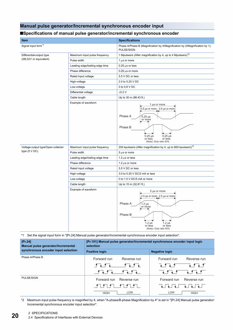
Manual pulse generator/Incremental synchronous encoder input
Specifications of manual pulse generator/incremental synchronous encoder
*1 Set the signal input form in "[Pr.24] Manual pulse generator/Incremental synchronous encoder input selection".
*2 Maximum input pulse frequency is magnified by 4, when "A-phase/B-phase Magnification by 4" is set in "[Pr.24] Manual pulse generator/Incremental synchronous encoder input selection".
Item Specifications
Signal input form*1 Phase A/Phase B (Magnification by 4/Magnification by 2/Magnification by 1),
PULSE/SIGN
Differential-output type
(26LS31 or equivalent)
Maximum input pulse frequency 1 Mpulses/s (After magnification by 4, up to 4 Mpulses/s)*2
Pulse width 1 s or more
Leading edge/trailing edge time 0.25 s or less
Phase difference 0.25 s or more
Rated input voltage 5.5 V DC or less
High-voltage 2.0 to 5.25 V DC
Low-voltage 0 to 0.8 V DC
Differential voltage 0.2 V
Cable length Up to 30 m (98.43 ft.)
Example of waveform
Voltage-output type/Open-collector
type (5 V DC)
Maximum input pulse frequency 200 kpulses/s (After magnification by 4, up to 800 kpulses/s)*2
Pulse width 5 s or more
Leading edge/trailing edge time 1.2 s or less
Phase difference 1.2 s or more
Rated input voltage 5.5 V DC or less
High-voltage 3.0 to 5.25 V DC/2 mA or less
Low-voltage 0 to 1.0 V DC/5 mA or more
Cable length Up to 10 m (32.81 ft.)
Example of waveform
[Pr.24]Manual pulse generator/Incremental synchronous encoder input selection
[Pr.151] Manual pulse generator/Incremental synchronous encoder input logic selection
Positive logic Negative logic
Phase A/Phase B
PULSE/SIGN
Phase A
0.5 μs or more 1 μs or more
Phase B
0.25 μs or less
0.25 μs or less
0.5 μs or more
0.25 μs or more
(Note): Duty ratio 50%
Phase A
2.5 μs or more
5 μs or more
Phase B
1.2 μs or less
1.2 μs or less
2.5 μs or more
1.2 μs or more
(Note): Duty ratio 50%
Forward run Reverse run Forward run Reverse run
Forward run Reverse run
HIGH LOW
Forward run Reverse run
HIGHLOW
2 SPECIFICATIONS2.4 Specifications of Interfaces with External Devices
2
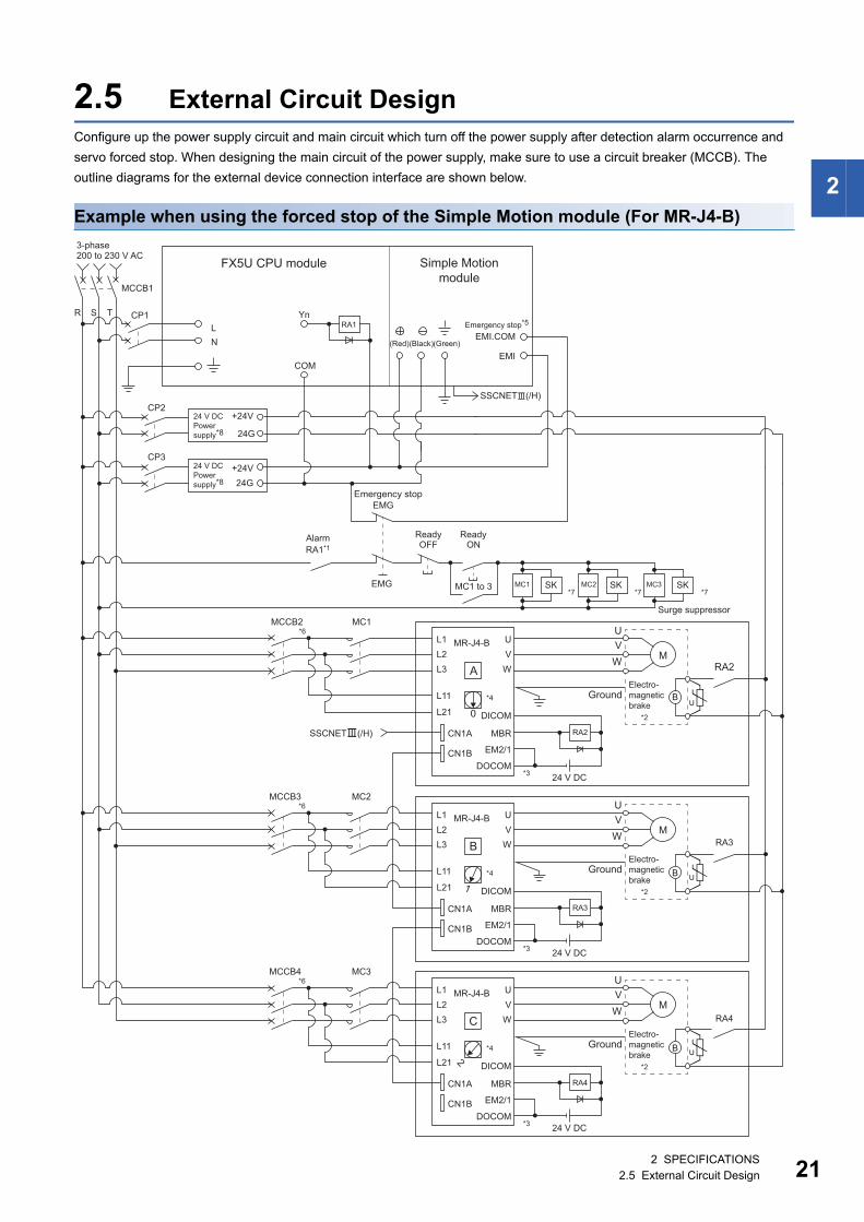
2.5 External Circuit DesignConfigure up the power supply circuit and main circuit which turn off the power supply after detection alarm occurrence and
servo forced stop. When designing the main circuit of the power supply, make sure to use a circuit breaker (MCCB). The
outline diagrams for the external device connection interface are shown below.
Example when using the forced stop of the Simple Motion module (For MR-J4-B)
0
1
2
Emergency stop
RA1*1Alarm
ONReadyOFF
3-phase200 to 230 V AC
R S T CP1
MCCB1
LN
EMI
EMI.COMEmergency stop*5
Yn
FX5U CPU module Simple Motionmodule
SSCNET(/H)
CP3+24V24G
CP2+24V
24G
24 V DCPower supply*8
(Red)(Black)(Green)
24 V DCPower supply*8
EMG
EMG
RA1
Ready
MC1 to 3 SK*7
SK*7
SK
Surge suppressor
*7
UVW
Ground
RA2
*6MCCB2 MC1
COM
M
*2
Electro-magneticbrake
MC1 MC2 MC3
L1L2L3
U
WV
L11
L21
CN1A
CN1B
DICOM
MBR
EM2/1
DOCOM
A
*4
MR-J4-B
*6MCCB3 MC2
*6MCCB4 MC3
SSCNET(/H)
UB
UVW
Ground
M
*2
Electro-magneticbrake UB
UVW
Ground
M
*2
Electro-magneticbrake UB
24 V DC*3
RA2
L1L2L3
U
WV
L11
L21
CN1A
CN1B
DICOM
MBR
EM2/1
DOCOM
B
*4
MR-J4-B
24 V DC*3
RA3
L1L2L3
U
WV
L11
L21
CN1A
CN1B
DICOM
MBR
EM2/1
DOCOM
C
*4
MR-J4-B
24 V DC*3
RA4
RA3
RA4
2 SPECIFICATIONS2.5 External Circuit Design 21

22
*1 Configure up the power supply circuit which switches off the electromagnetic contactor (MC) after detecting the alarm occurrence on the CPU module.
*2 It is also possible to use a full wave rectified power supply as the power supply for the electromagnetic brake.*3 It is also possible to perform the forced stop using a forced stop terminal of the servo amplifier.*4 Set the axis selection rotary switch of servo amplifier as follows to set the axis No. of servo amplifier.
Axis 1: 0, Axis 2: 1, Axis 3: 2, Axis 4: 3*5 The status of forced stop input signal can be confirmed with "[Md.50] Forced stop input". Be sure that the forced stop 24 V DC power
supply is not used with the electromagnetic brake of the motor or the electromagnetic valve power supply.*6 Refer to the servo amplifier instruction manual for selection of the circuit breaker and electromagnetic contactor.*7 The surge suppressor is recommended to be used for an AC relay or electromagnetic contactor (MC) near the servo amplifier.
Refer to the servo amplifier instruction manual for selection of the surge suppressor.*8 Wire the electromagnetic brake power supply and the control power supply using a separate power supply.
Precautions
• Be sure to shut off the both of main circuit power supply L1/L2/L3 and control power supply L11/L21 after disconnection of
SSCNET communication by the connect/disconnect function of SSCNET communication at the time of exchange of servo
amplifier. At this time, it is not possible to communicate between the servo amplifier and Simple Motion module. Therefore,
be sure to exchange the servo amplifier after stopping the operating of machine beforehand.
• If the emergency stop signal of Simple Motion module turns OFF when setting of "[Pr.82] Forced stop valid/invalid
selection" to "0: Valid", servomotor is stopped with dynamic brake. (The LED display of servo amplifier indicates "E7.1"
(Controller forced stop input warning).)
• When the control power supply of servo amplifier is shut off, it is not possible to communicate with the servo amplifier after
that.
Ex.
When the control power supply L11/L21 of the servo amplifier B in the figure is shut off, it is also not possible to communicate
with the servo amplifier C.
If only a specific servo amplifier main circuit power supply is shut off, be sure to shut off the main circuit power supply L1/L2/
L3, and do not shut off the control power supply L11/L21.
2 SPECIFICATIONS2.5 External Circuit Design
2
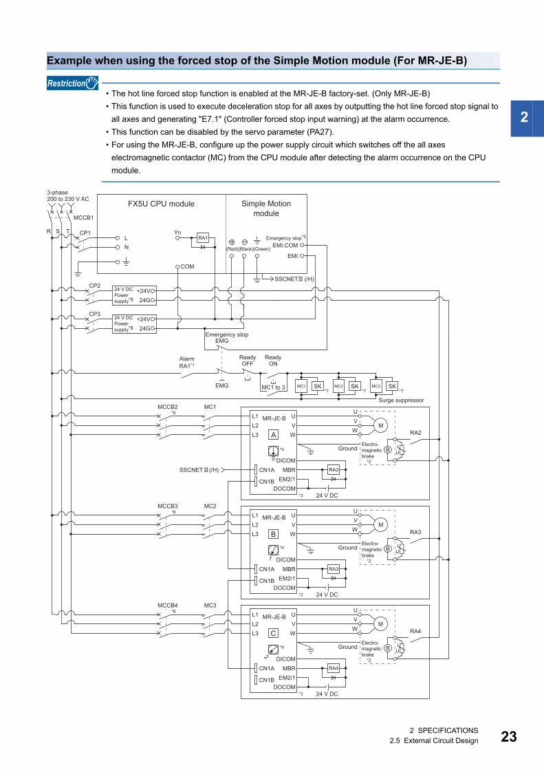
Example when using the forced stop of the Simple Motion module (For MR-JE-B)
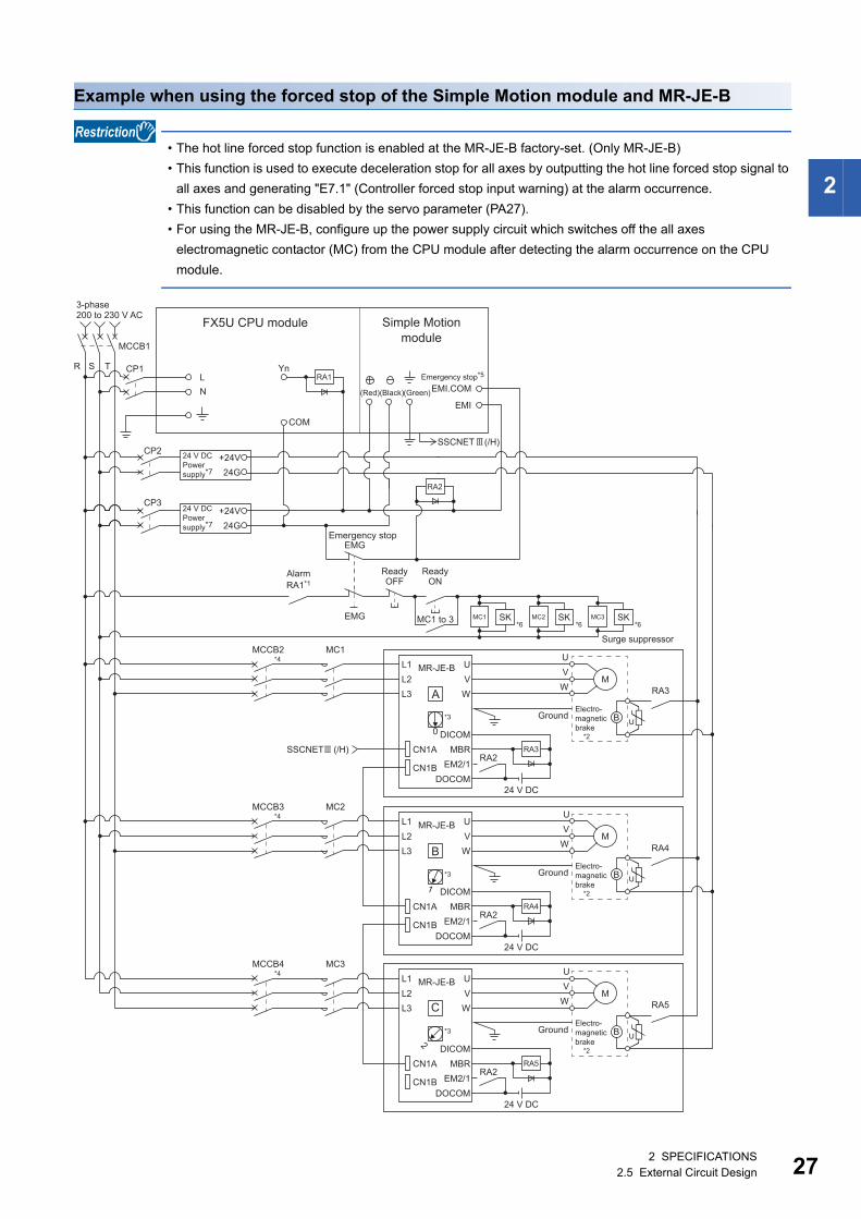
• The hot line forced stop function is enabled at the MR-JE-B factory-set. (Only MR-JE-B)
• This function is used to execute deceleration stop for all axes by outputting the hot line forced stop signal to
all axes and generating "E7.1" (Controller forced stop input warning) at the alarm occurrence.
• This function can be disabled by the servo parameter (PA27).
• For using the MR-JE-B, configure up the power supply circuit which switches off the all axes
electromagnetic contactor (MC) from the CPU module after detecting the alarm occurrence on the CPU
module.
U
Emergency stop
RA1*1Alarm
MC1 to 3 SK
ONReadyOFF
*7SK
*7SK
Surge suppressor
*7
L1L2L3
U
WV
CN1A
CN1B
DICOMMBR
EM2/1DOCOM
24 V DC
UVW
*3
Ground
L1L2L3
U
WV
CN1A
CN1B
DICOMMBR
EM2/1DOCOM
24 V DC
UVW
*3
Ground
A
B
L1L2L3
U
WV
CN1A
CN1B
DICOMMBR
EM2/1DOCOM
24 V DC
UVW
*3
Ground
C
0
1
2
*4
*4
*4
RA2
RA3
RA4
*6MCCB2 MC1
*6MCCB3 MC2
*6MCCB4 MC3
COM
3-phase200 to 230 V AC
R S T CP1
MCCB1
LN
EMI
EMI.COMEmergency stop*5
Yn
FX5U CPU module Simple Motionmodule
SSCNET (/H)
SSCNET (/H)
CP3+24V24G
M
*2
Electro-magneticbrake
CP2+24V24G
24 V DCPower supply*8
(Red)(Black)(Green)
24 V DCPower supply*8
MR-JE-B
MR-JE-B
MR-JE-B
M
*2
Electro-magneticbrake
*2
B
UB
UB
EMG
EMG MC1 MC2 MC3
RA1
RA2
RA3
RA4
M
Electro-magneticbrake
Ready
2 SPECIFICATIONS2.5 External Circuit Design 23
24
*1 Configure up the power supply circuit which switches off the electromagnetic contactor (MC) after detecting the alarm occurrence on the CPU module.
*2 It is also possible to use a full wave rectified power supply as the power supply for the electromagnetic brake.*3 It is also possible to perform the forced stop using a forced stop terminal of the servo amplifier.*4 Set the axis selection rotary switch of servo amplifier as follows to set the axis No. of servo amplifier.
Axis 1: 0, Axis 2: 1, Axis 3: 2, Axis 4: 3*5 The status of forced stop input signal can be confirmed with "[Md.50] Forced stop input". Be sure that the forced stop 24 V DC power
supply is not used with the electromagnetic brake of the motor or the electromagnetic valve power supply.*6 Refer to the servo amplifier instruction manual for selection of the circuit breaker and electromagnetic contactor.*7 The surge suppressor is recommended to be used for an AC relay or electromagnetic contactor (MC) near the servo amplifier.
Refer to the servo amplifier instruction manual for selection of the surge suppressor.*8 Wire the electromagnetic brake power supply and the control power supply using a separate power supply.
Precautions
• Be sure to shut off the both of main circuit power supply L1/L2/L3 and control power supply L11/L21 after disconnection of
SSCNET communication by the connect/disconnect function of SSCNET communication at the time of exchange of servo
amplifier. At this time, it is not possible to communicate between the servo amplifier and Simple Motion module. Therefore,
be sure to exchange the servo amplifier after stopping the operating of machine beforehand.
• If the emergency stop signal of Simple Motion module turns OFF when setting of "[Pr.82] Forced stop valid/invalid
selection" to "0: Valid", servomotor is stopped with dynamic brake. (The LED display of servo amplifier indicates "E7.1"
(Controller forced stop input warning).)
• When the control power supply of servo amplifier is shut off, it is not possible to communicate with the servo amplifier after
that.
Ex.
When the control power supply L11/L21 of the servo amplifier B in the figure is shut off, it is also not possible to communicate
with the servo amplifier C.
If only a specific servo amplifier main circuit power supply is shut off, be sure to shut off the main circuit power supply L1/L2/
L3, and do not shut off the control power supply L11/L21.
2 SPECIFICATIONS2.5 External Circuit Design
2
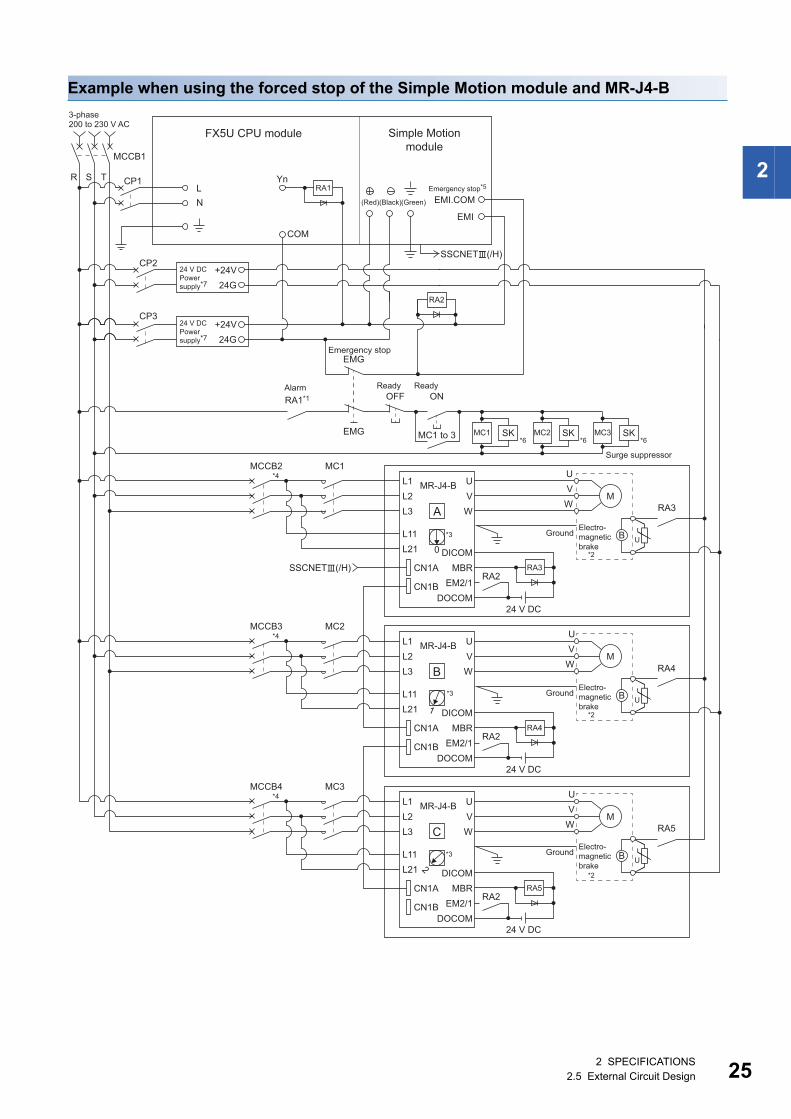
Example when using the forced stop of the Simple Motion module and MR-J4-B
0
1
2
CP2+24V24G
CP3+24V24G
EMG
R S T CP1
MCCB1
LN
SSCNET(/H)
EMI
EMI.COM
COM
YnRA1
RA2
RA1*1
MC1 to 3 SK
ONOFF
*6SK
*6SK
*6EMG MC1 MC2 MC3
L1L2L3
U
WV
L11L21
CN1A
CN1B
DICOMMBR
EM2/1DOCOM
24 V DC
UVW
*2
A
*3
RA3
*4MCCB2 MC1
SSCNET(/H)RA2
MR-J4-BM
UB
RA3
*2
L1L2L3
U
WV
L11L21
CN1A
CN1B
DICOMMBR
EM2/1DOCOM
24 V DC
UV
WB
*3
RA4
*4MCCB3 MC2
RA2
MR-J4-BM
UB
RA4
L1L2L3
U
WV
L11L21
CN1A
CN1B
DICOMMBR
EM2/1DOCOM
24 V DC
UV
WC
*3
RA5
*4MCCB4 MC3
*2
RA2
MR-J4-BM
UB
RA5
FX5U CPU module Simple Motionmodule
3-phase200 to 230 V AC
(Red)(Black)(Green)
24 V DCPower supply*7
24 V DCPower supply*7
Alarm ReadyReady
Emergency stop
Surge suppressor
GroundElectro-magneticbrake
GroundElectro-magneticbrake
GroundElectro-magneticbrake
Emergency stop*5
2 SPECIFICATIONS2.5 External Circuit Design 25
26
*1 Configure up the power supply circuit which switches off the electromagnetic contactor (MC) after detecting the alarm occurrence on the CPU module.
*2 It is also possible to use a full wave rectified power supply as the power supply for the electromagnetic brake.*3 Set the axis selection rotary switch of servo amplifier as follows to set the axis No. of servo amplifier.
Axis 1: 0, Axis 2: 1, Axis 3: 2, Axis 4: 3*4 Refer to the servo amplifier instruction manual for selection of the circuit breaker and electromagnetic contactor.*5 The status of forced stop input signal can be confirmed with "[Md.50] Forced stop input". Be sure that the forced stop 24 V DC power
supply is not used with the electromagnetic brake of the motor or the electromagnetic valve power supply.*6 The surge suppressor is recommended to be used for an AC relay or electromagnetic contactor (MC) near the servo amplifier.
Refer to the servo amplifier instruction manual for selection of the surge suppressor.*7 Wire the electromagnetic brake power supply and the control power supply using a separate power supply.
Precautions
• Be sure to shut off the both of main circuit power supply L1/L2/L3 and control power supply L11/L21 after disconnection of
SSCNET communication by the connect/disconnect function of SSCNET communication at the time of exchange of servo
amplifier. At this time, it is not possible to communicate between the servo amplifier and Simple Motion module. Therefore,
be sure to exchange the servo amplifier after stopping the operating of machine beforehand.
• The dynamic brake operates and servomotor occurs to the free run when EM1 (forced stop) of the servo amplifier is turned
OFF. At the time, the display shows "E6.1" (Forced stop warning). During ordinary operation, do not use EM1 (forced stop)
of the servo amplifier to alternate stop and run. The service life of the servo amplifier may be shortened.
• When the control power supply of servo amplifier is shut off, it is not possible to communicate with the servo amplifier after
that.
Ex.
When the control power supply L11/L21 of the servo amplifier B in the figure is shut off, it is also not possible to communicate
with the servo amplifier C.
If only a specific servo amplifier main circuit power supply is shut off, be sure to shut off the main circuit power supply L1/L2/
L3, and do not shut off the control power supply L11/L21.
2 SPECIFICATIONS2.5 External Circuit Design
2
Example when using the forced stop of the Simple Motion module and MR-JE-B
• The hot line forced stop function is enabled at the MR-JE-B factory-set. (Only MR-JE-B)
• This function is used to execute deceleration stop for all axes by outputting the hot line forced stop signal to
all axes and generating "E7.1" (Controller forced stop input warning) at the alarm occurrence.
• This function can be disabled by the servo parameter (PA27).
• For using the MR-JE-B, configure up the power supply circuit which switches off the all axes
electromagnetic contactor (MC) from the CPU module after detecting the alarm occurrence on the CPU
module.
CP2+24V24G
CP3+24V24G
RA1*1Alarm
MC1 to 3 SK
ReadyON
ReadyOFF
*6SK
*6SK
Surge suppressor
*6
L1L2L3
MR-JE-B U
WV
CN1A
CN1B
DICOMMBR
EM2/1DOCOM
UVW
L1L2L3
U
WV
CN1A
CN1B
DICOMMBR
EM2/1DOCOM
UV
W
A
B
L1L2L3
U
WV
CN1A
CN1B
DICOMMBR
EM2/1DOCOM
UV
WC
0
1
2
*3
RA3
RA4
RA5
*4MCCB2 MC1
*4MCCB3 MC2
*4MCCB4 MC3
MCCB1
LN
COM
Yn
SSCNET (/H)
SSCNET (/H)RA2
RA2
RA2
R S T CP1
EMI
EMI.COMEmergency stop*5
FX5U CPU module Simple Motionmodule
(Red)(Black)(Green)
3-phase200 to 230 V AC
24 V DCPower supply*7
24 V DCPower supply*7
Emergency stop
MR-JE-B
*3
24 V DC
24 V DC
MR-JE-B
*3
24 V DC
Ground
M
*2
Electro-magneticbrake
Ground
M
*2
Electro-magneticbrake
Ground
M
*2
Electro-magneticbrake
EMG
EMG
RA1
RA2
MC1 MC2 MC3
RA3
RA4
RA5
UB
UB
UB
2 SPECIFICATIONS2.5 External Circuit Design 27

28
*1 Configure up the power supply circuit which switches off the electromagnetic contactor (MC) after detecting the alarm occurrence on the CPU module.
*2 It is also possible to use a full wave rectified power supply as the power supply for the electromagnetic brake.*3 Set the axis selection rotary switch of servo amplifier as follows to set the axis No. of servo amplifier.
Axis 1: 0, Axis 2: 1, Axis 3: 2, Axis 4: 3*4 Refer to the servo amplifier instruction manual for selection of the circuit breaker and electromagnetic contactor.*5 The status of forced stop input signal can be confirmed with "[Md.50] Forced stop input". Be sure that the forced stop 24 V DC power
supply is not used with the electromagnetic brake of the motor or the electromagnetic valve power supply.*6 The surge suppressor is recommended to be used for an AC relay or electromagnetic contactor (MC) near the servo amplifier.
Refer to the servo amplifier instruction manual for selection of the surge suppressor.*7 Wire the electromagnetic brake power supply and the control power supply using a separate power supply.
Precautions
• Be sure to shut off the both of main circuit power supply L1/L2/L3 and control power supply L11/L21 after disconnection of
SSCNET communication by the connect/disconnect function of SSCNET communication at the time of exchange of servo
amplifier. At this time, it is not possible to communicate between the servo amplifier and Simple Motion module. Therefore,
be sure to exchange the servo amplifier after stopping the operating of machine beforehand.
• The dynamic brake operates and servomotor occurs to the free run when EM1 (forced stop) of the servo amplifier is turned
OFF. At the time, the display shows "E6.1" (Forced stop warning). During ordinary operation, do not use EM1 (forced stop)
of the servo amplifier to alternate stop and run. The service life of the servo amplifier may be shortened.
• When the control power supply of servo amplifier is shut off, it is not possible to communicate with the servo amplifier after
that.
Ex.
When the control power supply L11/L21 of the servo amplifier B in the figure is shut off, it is also not possible to communicate
with the servo amplifier C.
If only a specific servo amplifier main circuit power supply is shut off, be sure to shut off the main circuit power supply L1/L2/
L3, and do not shut off the control power supply L11/L21.
2 SPECIFICATIONS2.5 External Circuit Design
3
3 FUNCTION LIST
3.1 Control FunctionsThe Simple Motion module has several functions. Refer to the following for details on each function.
MELSEC iQ-F FX5 Simple Motion Module User's Manual (Application)
In this manual, the Simple Motion module functions are categorized and explained as follows.
Main functions
Home position return control"Home position return control" is a function (Fast home position return) that established the start point for carrying out
positioning control (Machine home position return), and carries out positioning toward that start point. This is used to return a
workpiece, located at a position other than the home position when the power is turned ON or after positioning stop, to the
home position. The "home position return control" is pre-registered in the Simple Motion module as the "Positioning start data
No. 9001 (Machine home position return)", and "Positioning start data No. 9002 (Fast home position return)".
Major positioning controlThis control is carried out using the "Positioning data" stored in the Simple Motion module. Positioning control, such as
position control and speed control, is executed by setting the required items in this "positioning data" and starting that
positioning data. An "operation pattern" can be set in this "positioning data", and with this whether to carry out control with
continuous positioning data (ex.: positioning data No. 1, No. 2, No. 3, etc.) can be set.
High-level positioning controlThis control executes the "positioning data" stored in the Simple Motion module using the "block start data". The following
types of applied positioning control can be carried out.
• Random blocks, handling several continuing positioning data items as "blocks", can be executed in the designated order.
• "Condition judgment" can be added to position control and speed control.
• The operation of the positioning data that is set for multiple axes can be started simultaneously. (Command is output
simultaneously to multiple servo amplifiers.)
• The designated positioning data can be executed repeatedly,
etc.
Manual controlThe Simple Motion module executes the random positioning operation by inputting a signal into the Simple Motion module
from an external device.
Use this manual control to move the workpiece to a random position (JOG operation), and to finely adjust the positioning
(inching operation, manual pulse generator operation), etc.
Expansion controlThe following controls other than the positioning control can be executed.
• Speed control and torque control not including position loop for the command to servo amplifier (Speed-torque control).
• Synchronous control with gear, shaft, change gear and cam not by mechanical, but by software use "synchronous control
parameter", and is synchronized with input axis (Synchronous control).
3 FUNCTION LIST3.1 Control Functions 29
30
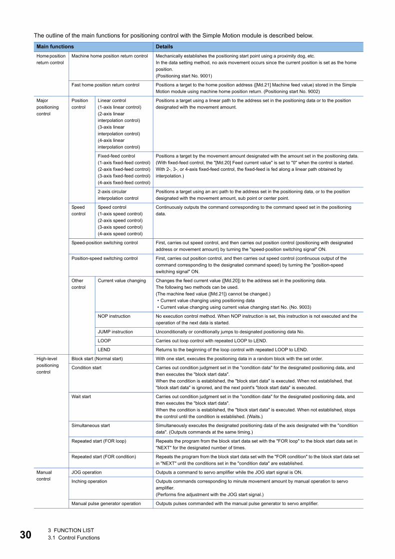
The outline of the main functions for positioning control with the Simple Motion module is described below.
Main functions Details
Home position
return control
Machine home position return control Mechanically establishes the positioning start point using a proximity dog, etc.
In the data setting method, no axis movement occurs since the current position is set as the home
position.
(Positioning start No. 9001)
Fast home position return control Positions a target to the home position address ([Md.21] Machine feed value) stored in the Simple
Motion module using machine home position return. (Positioning start No. 9002)
Major
positioning
control
Position
control
Linear control
(1-axis linear control)
(2-axis linear
interpolation control)
(3-axis linear
interpolation control)
(4-axis linear
interpolation control)
Positions a target using a linear path to the address set in the positioning data or to the position
designated with the movement amount.
Fixed-feed control
(1-axis fixed-feed control)
(2-axis fixed-feed control)
(3-axis fixed-feed control)
(4-axis fixed-feed control)
Positions a target by the movement amount designated with the amount set in the positioning data.
(With fixed-feed control, the "[Md.20] Feed current value" is set to "0" when the control is started.
With 2-, 3-, or 4-axis fixed-feed control, the fixed-feed is fed along a linear path obtained by
interpolation.)
2-axis circular
interpolation control
Positions a target using an arc path to the address set in the positioning data, or to the position
designated with the movement amount, sub point or center point.
Speed
control
Speed control
(1-axis speed control)
(2-axis speed control)
(3-axis speed control)
(4-axis speed control)
Continuously outputs the command corresponding to the command speed set in the positioning
data.
Speed-position switching control First, carries out speed control, and then carries out position control (positioning with designated
address or movement amount) by turning the "speed-position switching signal" ON.
Position-speed switching control First, carries out position control, and then carries out speed control (continuous output of the
command corresponding to the designated command speed) by turning the "position-speed
switching signal" ON.
Other
control
Current value changing Changes the feed current value ([Md.20]) to the address set in the positioning data.
The following two methods can be used.
(The machine feed value ([Md.21]) cannot be changed.)
• Current value changing using positioning data
• Current value changing using current value changing start No. (No. 9003)
NOP instruction No execution control method. When NOP instruction is set, this instruction is not executed and the
operation of the next data is started.
JUMP instruction Unconditionally or conditionally jumps to designated positioning data No.
LOOP Carries out loop control with repeated LOOP to LEND.
LEND Returns to the beginning of the loop control with repeated LOOP to LEND.
High-level
positioning
control
Block start (Normal start) With one start, executes the positioning data in a random block with the set order.
Condition start Carries out condition judgment set in the "condition data" for the designated positioning data, and
then executes the "block start data".
When the condition is established, the "block start data" is executed. When not established, that
"block start data" is ignored, and the next point's "block start data" is executed.
Wait start Carries out condition judgment set in the "condition data" for the designated positioning data, and
then executes the "block start data".
When the condition is established, the "block start data" is executed. When not established, stops
the control until the condition is established. (Waits.)
Simultaneous start Simultaneously executes the designated positioning data of the axis designated with the "condition
data". (Outputs commands at the same timing.)
Repeated start (FOR loop) Repeats the program from the block start data set with the "FOR loop" to the block start data set in
"NEXT" for the designated number of times.
Repeated start (FOR condition) Repeats the program from the block start data set with the "FOR condition" to the block start data set
in "NEXT" until the conditions set in the "condition data" are established.
Manual
control
JOG operation Outputs a command to servo amplifier while the JOG start signal is ON.
Inching operation Outputs commands corresponding to minute movement amount by manual operation to servo
amplifier.
(Performs fine adjustment with the JOG start signal.)
Manual pulse generator operation Outputs pulses commanded with the manual pulse generator to servo amplifier.
3 FUNCTION LIST3.1 Control Functions
3
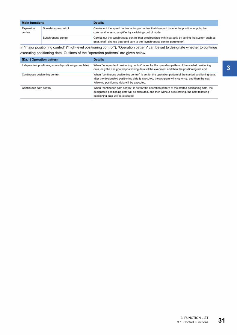
In "major positioning control" ("high-level positioning control"), "Operation pattern" can be set to designate whether to continue
executing positioning data. Outlines of the "operation patterns" are given below.
Expansion
control
Speed-torque control Carries out the speed control or torque control that does not include the position loop for the
command to servo amplifier by switching control mode.
Synchronous control Carries out the synchronous control that synchronizes with input axis by setting the system such as
gear, shaft, change gear and cam to the "synchronous control parameter".
[Da.1] Operation pattern Details
Independent positioning control (positioning complete) When "independent positioning control" is set for the operation pattern of the started positioning
data, only the designated positioning data will be executed, and then the positioning will end.
Continuous positioning control When "continuous positioning control" is set for the operation pattern of the started positioning data,
after the designated positioning data is executed, the program will stop once, and then the next
following positioning data will be executed.
Continuous path control When "continuous path control" is set for the operation pattern of the started positioning data, the
designated positioning data will be executed, and then without decelerating, the next following
positioning data will be executed.
Main functions Details
3 FUNCTION LIST3.1 Control Functions 31
32
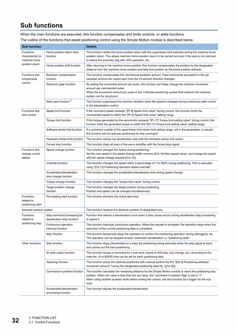
Sub functionsWhen the main functions are executed, this function compensates and limits controls, or adds functions.
The outline of the functions that assist positioning control using the Simple Motion module is described below.
Sub function Details
Functions
characteristic to
machine home
position return
Home position return retry
function
This function retries the home position return with the upper/lower limit switches during the machine home
position return. This allows machine home position return to be carried out even if the axis is not returned
to before the proximity dog with JOG operation, etc.
Home position shift function After returning to the machine home position, this function compensates the position by the designated
distance from the machine home position and sets that position as the home position address.
Functions that
compensate
control
Backlash compensation
function
This function compensates the mechanical backlash amount. Feed commands equivalent to the set
backlash amount are output each time the movement direction changes.
Electronic gear function By setting the movement amount per pulse, this function can freely change the machine movement
amount per commanded pulse.
When the movement amount per pulse is set, a flexible positioning system that matches the machine
system can be structured.
Near pass function*1 This function suppresses the machine vibration when the speed is changed during continuous path control
in the interpolation control.
Functions that
limit control
Speed limit function If the command speed exceeds "[Pr.8] Speed limit value" during control, this function limits the
commanded speed to within the "[Pr.8] Speed limit value" setting range.
Torque limit function If the torque generated by the servomotor exceeds "[Pr.17] Torque limit setting value" during control, this
function limits the generated torque to within the "[Pr.17] Torque limit setting value" setting range.
Software stroke limit function If a command outside of the upper/lower limit stroke limit setting range, set in the parameters, is issued,
this function will not execute positioning for that command.
Hardware stroke limit function This function carries out deceleration stop with the hardware stroke limit switch.
Forced stop function This function stops all axes of the servo amplifier with the forced stop signal.
Functions that
change control
details
Speed change function This function changes the speed during positioning.
Set the new speed in the speed change buffer memory ([Cd.14] New speed value), and change the speed
with the speed change request ([Cd.15]).
Override function This function changes the speed within a percentage of 1 to 300% during positioning. This is executed
using "[Cd.13] Positioning operation speed override".
Acceleration/deceleration
time change function
This function changes the acceleration/deceleration time during speed change.
Torque change function This function changes the "torque limit value" during control.
Target position change
function
This function changes the target position during positioning.
Position and speed can be changed simultaneously.
Functions
related to
positioning start
Pre-reading start function This function shortens the virtual start time.
Absolute position system This function restores the absolute position of designated axis.
Functions
related to
positioning stop
Stop command processing for
deceleration stop function
Function that selects a deceleration curve when a stop cause occurs during deceleration stop processing
to speed 0.
Continuous operation
interrupt function
This function interrupts continuous operation. When this request is accepted, the operation stops when the
execution of the current positioning data is completed.
Step function This function temporarily stops the operation to confirm the positioning operation during debugging, etc.
The operation can be stopped at each "automatic deceleration" or "positioning data".
Other functions Skip function This function stops (decelerates to a stop) the positioning being executed when the skip signal is input,
and carries out the next positioning.
M code output function This function issues a command for a sub work (clamp or drill stop, tool change, etc.) according to the
code No. (0 to 65535) that can be set for each positioning data.
Teaching function This function stores the address positioned with manual control into the "[Da.6] Positioning address/
movement amount" having the designated positioning data No. ([Cd.39]).
Command in-position function This function calculates the remaining distance for the Simple Motion module to reach the positioning stop
position. When the value is less than the set value, the "command in-position flag" is set to "1".
When using another auxiliary work before ending the control, use this function as a trigger for the sub
work.
Acceleration/deceleration
processing function
This function adjusts the acceleration/deceleration.
3 FUNCTION LIST3.1 Control Functions

3
*1 The near pass function is featured as standard and is valid only for setting continuous path control for position control. It cannot be set to be invalid with parameters.
Other functions Deceleration start flag
function
Function that turns ON the flag when the constant speed status or acceleration status switches to the
deceleration status during position control, whose operation pattern is "Positioning complete", to make the
stop timing known.
Follow up function This function monitors the motor rotation amount with the servo turned OFF, and reflects it on the feed
current value.
Speed control 10 times
multiplier setting for degree
axis function
This function executes the positioning control by the 10 times speed of the command speed and the speed
limit value when the setting unit is "degree".
Operation setting for
incompletion of home position
return function
This function is provided to select whether positioning control is operated or not, when the home position
return request flag is ON.
Sub function Details
3 FUNCTION LIST3.1 Control Functions 33
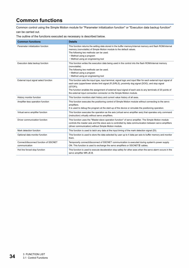
34
Common functionsCommon control using the Simple Motion module for "Parameter initialization function" or "Execution data backup function"
can be carried out.
The outline of the functions executed as necessary is described below.
Common functions Details
Parameter initialization function This function returns the setting data stored in the buffer memory/internal memory and flash ROM/internal
memory (nonvolatile) of Simple Motion module to the default values.
The following two methods can be used.
• Method using a program
• Method using an engineering tool
Execution data backup function This function writes the execution data being used in the control into the flash ROM/internal memory
(nonvolatile).
The following two methods can be used.
• Method using a program
• Method using an engineering tool
External input signal select function This function sets the input type, input terminal, signal logic and input filter for each external input signal of
each axis (upper/lower stroke limit signal (FLS/RLS), proximity dog signal (DOG), and stop signal
(STOP)).
The function enables the assignment of external input signal of each axis to any terminals of 20 points of
the external input connection connector on the Simple Motion module.
History monitor function This function monitors start history and current value history of all axes.
Amplifier-less operation function This function executes the positioning control of Simple Motion module without connecting to the servo
amplifiers.
It is used to debug the program at the start-up of the device or simulate the positioning operation.
Virtual servo amplifier function This function executes the operation as the axis (virtual servo amplifier axis) that operates only command
(instruction) virtually without servo amplifiers.
Driver communication function This function uses the "Master-slave operation function" of servo amplifier. The Simple Motion module
controls the master axis and the slave axis is controlled by data communication between servo amplifiers
(driver communication) without Simple Motion module.
Mark detection function This function is used to latch any data at the input timing of the mark detection signal (DI).
Optional data monitor function This function is used to store the data selected by user up to 4 data per axis to buffer memory and monitor
them.
Connect/disconnect function of SSCNET
communication
Temporarily connect/disconnect of SSCNET communication is executed during system's power supply
ON. This function is used to exchange the servo amplifiers or SSCNET cables.
Hot line forced stop function This function is used to execute deceleration stop safety for other axes when the servo alarm occurs in the
servo amplifier MR-JE-B.
3 FUNCTION LIST3.1 Control Functions
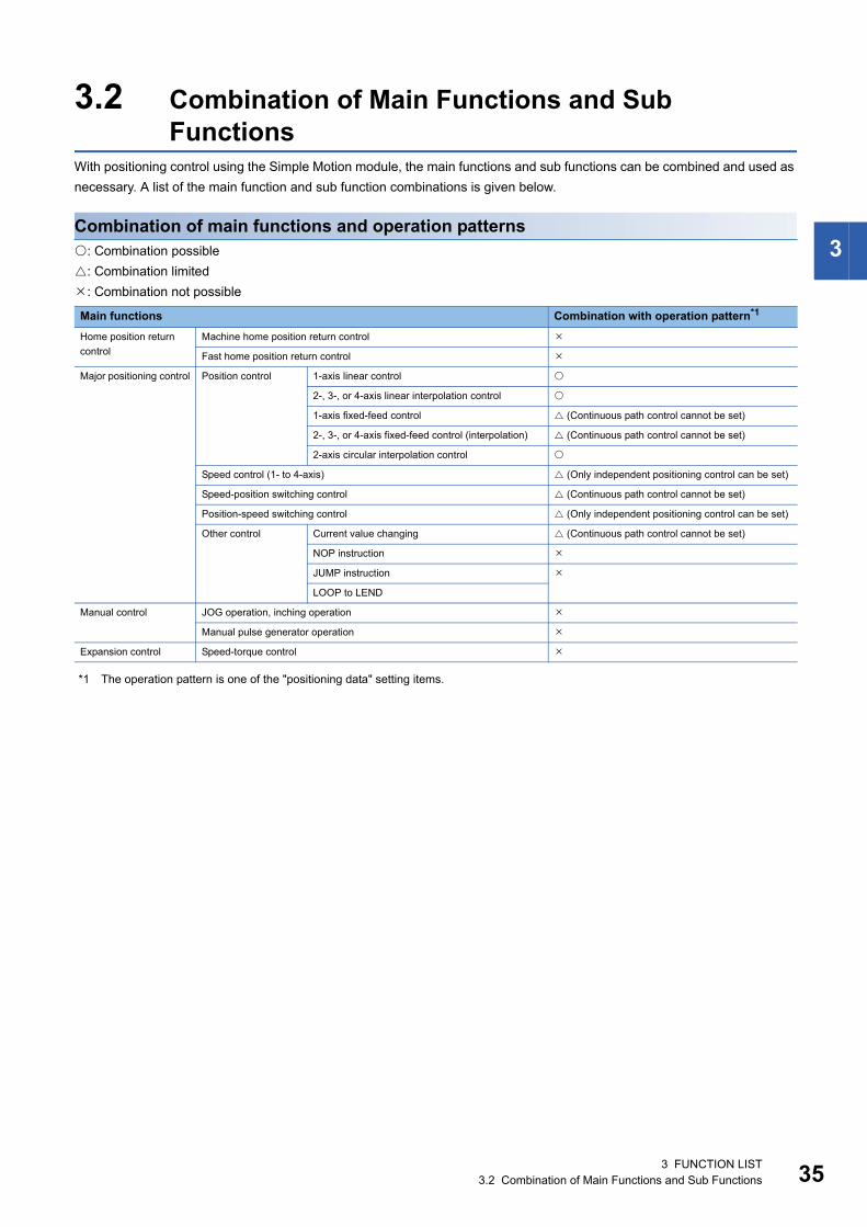
3
3.2 Combination of Main Functions and Sub Functions
With positioning control using the Simple Motion module, the main functions and sub functions can be combined and used as
necessary. A list of the main function and sub function combinations is given below.
Combination of main functions and operation patterns: Combination possible
: Combination limited
: Combination not possible
*1 The operation pattern is one of the "positioning data" setting items.
Main functions Combination with operation pattern*1
Home position return
control
Machine home position return control
Fast home position return control
Major positioning control Position control 1-axis linear control
2-, 3-, or 4-axis linear interpolation control
1-axis fixed-feed control (Continuous path control cannot be set)
2-, 3-, or 4-axis fixed-feed control (interpolation) (Continuous path control cannot be set)
2-axis circular interpolation control
Speed control (1- to 4-axis) (Only independent positioning control can be set)
Speed-position switching control (Continuous path control cannot be set)
Position-speed switching control (Only independent positioning control can be set)
Other control Current value changing (Continuous path control cannot be set)
NOP instruction
JUMP instruction
LOOP to LEND
Manual control JOG operation, inching operation
Manual pulse generator operation
Expansion control Speed-torque control
3 FUNCTION LIST3.2 Combination of Main Functions and Sub Functions 35
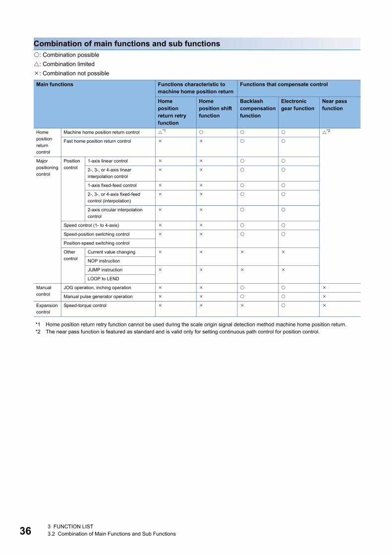
36
Combination of main functions and sub functions: Combination possible
: Combination limited
: Combination not possible
*1 Home position return retry function cannot be used during the scale origin signal detection method machine home position return.*2 The near pass function is featured as standard and is valid only for setting continuous path control for position control.
Main functions Functions characteristic to machine home position return
Functions that compensate control
Home position return retry function
Home position shift function
Backlash compensation function
Electronic gear function
Near pass function
Home
position
return
control
Machine home position return control *1 *2
Fast home position return control
Major
positioning
control
Position
control
1-axis linear control
2-, 3-, or 4-axis linear
interpolation control
1-axis fixed-feed control
2-, 3-, or 4-axis fixed-feed
control (interpolation)
2-axis circular interpolation
control
Speed control (1- to 4-axis)
Speed-position switching control
Position-speed switching control
Other
control
Current value changing
NOP instruction
JUMP instruction
LOOP to LEND
Manual
control
JOG operation, inching operation
Manual pulse generator operation
Expansion
control
Speed-torque control
3 FUNCTION LIST3.2 Combination of Main Functions and Sub Functions
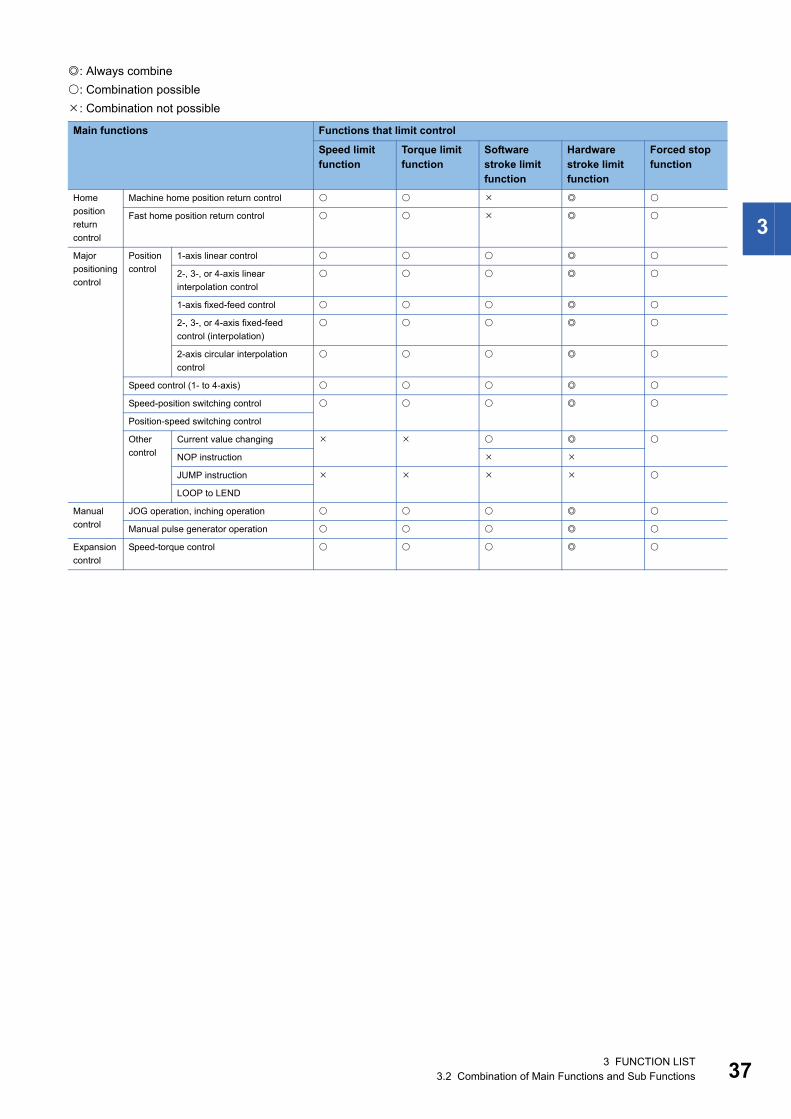
3
: Always combine
: Combination possible
: Combination not possible
Main functions Functions that limit control
Speed limit function
Torque limit function
Software stroke limit function
Hardware stroke limit function
Forced stop function
Home
position
return
control
Machine home position return control
Fast home position return control
Major
positioning
control
Position
control
1-axis linear control
2-, 3-, or 4-axis linear
interpolation control
1-axis fixed-feed control
2-, 3-, or 4-axis fixed-feed
control (interpolation)
2-axis circular interpolation
control
Speed control (1- to 4-axis)
Speed-position switching control
Position-speed switching control
Other
control
Current value changing
NOP instruction
JUMP instruction
LOOP to LEND
Manual
control
JOG operation, inching operation
Manual pulse generator operation
Expansion
control
Speed-torque control
3 FUNCTION LIST3.2 Combination of Main Functions and Sub Functions 37
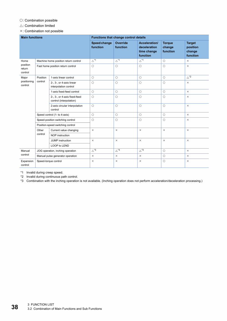
38
: Combination possible
: Combination limited
: Combination not possible
*1 Invalid during creep speed.*2 Invalid during continuous path control.*3 Combination with the inching operation is not available. (Inching operation does not perform acceleration/deceleration processing.)
Main functions Functions that change control details
Speed change function
Override function
Acceleration/ deceleration time change function
Torque change function
Target position change function
Home
position
return
control
Machine home position return control *1 *1 *1
Fast home position return control
Major
positioning
control
Position
control
1-axis linear control *2
2-, 3-, or 4-axis linear
interpolation control
1-axis fixed-feed control
2-, 3-, or 4-axis fixed-feed
control (interpolation)
2-axis circular interpolation
control
Speed control (1- to 4-axis)
Speed-position switching control
Position-speed switching control
Other
control
Current value changing
NOP instruction
JUMP instruction
LOOP to LEND
Manual
control
JOG operation, inching operation *3 *3 *3
Manual pulse generator operation
Expansion
control
Speed-torque control
3 FUNCTION LIST3.2 Combination of Main Functions and Sub Functions
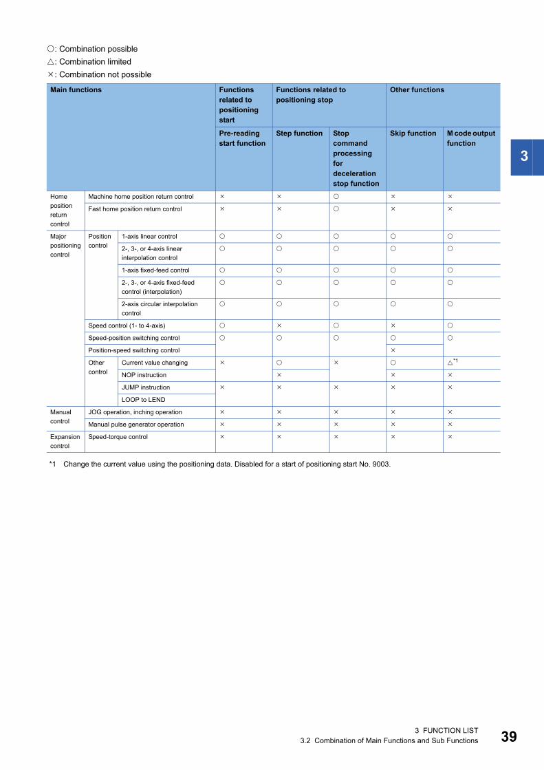
3
: Combination possible
: Combination limited
: Combination not possible
*1 Change the current value using the positioning data. Disabled for a start of positioning start No. 9003.
Main functions Functions related to positioning start
Functions related to positioning stop
Other functions
Pre-reading start function
Step function Stop command processing for deceleration stop function
Skip function M code output function
Home
position
return
control
Machine home position return control
Fast home position return control
Major
positioning
control
Position
control
1-axis linear control
2-, 3-, or 4-axis linear
interpolation control
1-axis fixed-feed control
2-, 3-, or 4-axis fixed-feed
control (interpolation)
2-axis circular interpolation
control
Speed control (1- to 4-axis)
Speed-position switching control
Position-speed switching control
Other
control
Current value changing *1
NOP instruction
JUMP instruction
LOOP to LEND
Manual
control
JOG operation, inching operation
Manual pulse generator operation
Expansion
control
Speed-torque control
3 FUNCTION LIST3.2 Combination of Main Functions and Sub Functions 39
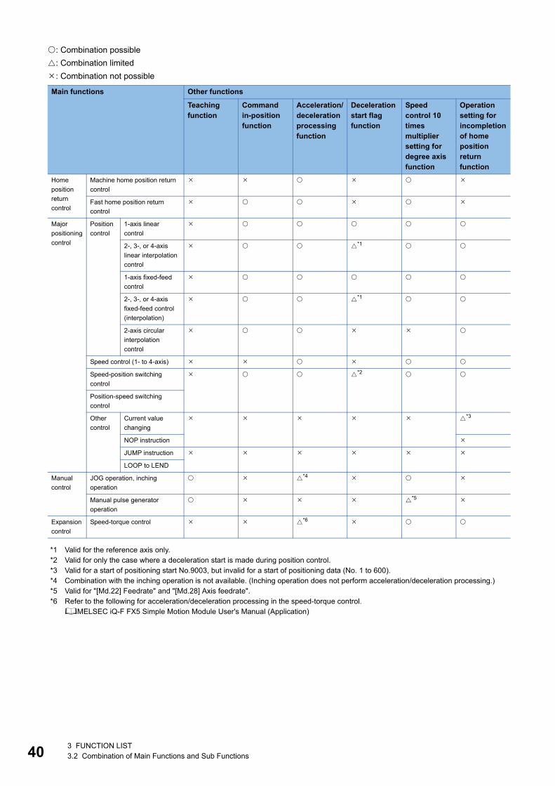
40
: Combination possible
: Combination limited
: Combination not possible
*1 Valid for the reference axis only.*2 Valid for only the case where a deceleration start is made during position control.*3 Valid for a start of positioning start No.9003, but invalid for a start of positioning data (No. 1 to 600).*4 Combination with the inching operation is not available. (Inching operation does not perform acceleration/deceleration processing.)*5 Valid for "[Md.22] Feedrate" and "[Md.28] Axis feedrate".*6 Refer to the following for acceleration/deceleration processing in the speed-torque control.
MELSEC iQ-F FX5 Simple Motion Module User's Manual (Application)
Main functions Other functions
Teaching function
Command in-position function
Acceleration/deceleration processing function
Deceleration start flag function
Speed control 10 times multiplier setting for degree axis function
Operation setting for incompletion of home position return function
Home
position
return
control
Machine home position return
control
Fast home position return
control
Major
positioning
control
Position
control
1-axis linear
control
2-, 3-, or 4-axis
linear interpolation
control
*1
1-axis fixed-feed
control
2-, 3-, or 4-axis
fixed-feed control
(interpolation)
*1
2-axis circular
interpolation
control
Speed control (1- to 4-axis)
Speed-position switching
control
*2
Position-speed switching
control
Other
control
Current value
changing
*3
NOP instruction
JUMP instruction
LOOP to LEND
Manual
control
JOG operation, inching
operation
*4
Manual pulse generator
operation
*5
Expansion
control
Speed-torque control *6
3 FUNCTION LIST3.2 Combination of Main Functions and Sub Functions
4
4 PROCEDURES BEFORE OPERATIONS
This chapter describes the procedures before operation.
1. Mounting the module
Mount the Simple Motion module to the CPU module.
For details, refer to the following.
MELSEC iQ-F FX5U User's Manual (Hardware)
MELSEC iQ-F FX5UC User's Manual (Hardware)
2. Wiring
Connect the Simple Motion module to external devices.
3. Adding the module
Add the FX5SSC to the module map of the project using an engineering tool.
4. Module setting
Set values for the module setting using an engineering tool.
For details, refer to the following.
GX Works3 Operating Manual
5. Auto refresh setting
Set values for the refresh settings using an engineering tool.
For details, refer to the following.
GX Works3 Operating Manual
6. Checking connection
Check that the Simple Motion module is connected to external devices correctly.
7. Programming
Create programs.
For details, refer to the following.
MELSEC iQ-F FX5 Simple Motion Module User's Manual (Application)
8. Test operation
Check that the positioning is correctly carried out as designed.
4 PROCEDURES BEFORE OPERATIONS 41

42
MEMO
4 PROCEDURES BEFORE OPERATIONS
5
5 WIRING
5.1 Precautions for WiringThe precautions for wiring the Simple Motion module are shown below. Execute the work following the precautions below.
Warning for wiring
Caution for wiring
WARNING• Completely turn off the externally supplied power used in the system before installation or wiring. Not doing so could result in electric shock or damage to the
product.
CAUTION• Check the layout of the terminals and then properly route the wires to the module.
• The external input wiring connector must be crimped or pressured with the tool specified by the manufacturer, or must be correctly soldered. Insufficient
connections may cause short circuit, fire, or malfunction.
• Be careful not to let foreign matter such as sawdust or wire chips get inside the module. These may cause fires, failure or malfunction.
• The top surface of the module is covered with protective films to prevent foreign objects such as cable off cuts from entering the module when wiring. Do not
remove this film until the wiring is complete. Before operating the system, be sure to remove the film to provide adequate ventilation.
• Securely connect the connector for SSCNET cable to the bottom connector on the module.
• When removing the cable from the module, do not pull the cable. Hold the connector that is connected to the module. Pulling the cable that is still connected
to the module may cause malfunction or damage to the module or cable.
• The external input/output signal cable and the communication cable should not be routed near or bundled with the main circuit cable, power cable and/or
other such load - carrying cables other than those for the PLC. These cables should be separated by at least 100 mm (3.94 inch) or more. They can cause
electrical interference, surges and inductance that can lead to mis-operation.
• The shielded cable for connecting Simple Motion module can be secured in place. If the shielded cable is not secured, unevenness or movement of the
shielded cable or careless pulling on it could result in damage to the Simple Motion module, servo amplifier or shielded cable or defective cable connections
could cause mis-operation of the unit.
• If the external input/output signal cable and the power line must be adjacently laid (less than 100 mm (3.94 inch)), use a shielded cable. Ground the shield of
the cable securely to the control panel on the Simple Motion module side.
• Forcibly removal the SSCNET cable from the Simple Motion module will damage the Simple Motion module and SSCNET cables.
• After removal of the SSCNET cable, be sure to put a cap on the SSCNET connector. Otherwise, adhesion of dirt deteriorates in characteristic and it may
cause malfunctions.
• Do not remove the SSCNET cable while turning on the power supply of Simple Motion module and servo amplifier. Do not see directly the light generated
from SSCNET connector and the end of SSCNET cable. When the light gets into eye, may feel something wrong with eyes.(The light source of
SSCNET cable complies with class1 defined in JISC6802 or IEC60825-1.)
• If a power such as a major shock, lateral pressure, haul, sudden bending or twist is added to the SSCNET cable, it distorts or breaks inside and optical
transmission is not be available. Note that the short SSCNET cable can be twisted easily.
• Be sure to use the SSCNET cable within the range of operating temperature described in each servo amplifier instruction manual. Especially, as optical
fiber for MR-J3BUS_M and MR-J3BUS_M-A are made of synthetic resin, it melts down if being left near the fire or high temperature. Therefore, do not make
it touched the part which becomes high temperature, such as radiator or regenerative option of servo amplifier, or servomotor.
• When laying the SSCNET cable, be sure to secure the minimum cable bend radius or more.
• Put the SSCNET cable in the duct or fix the cable at the closest part to the Simple Motion module with bundle material in order to prevent SSCNET cable
from putting its own weight on SSCNET connector. When laying cable, the optical cord should be given loose slack to avoid from becoming smaller than
the minimum bend radius, and it should not be twisted. Also, fix and hold it in position with using cushioning such as sponge or rubber which does not contain
plasticizing material. If adhesive tape for bundling the cable is used, fire resistant acetate cloth adhesive tape 570F (Teraoka Seisakusho Co., Ltd) is
recommended.
5 WIRING5.1 Precautions for Wiring 43
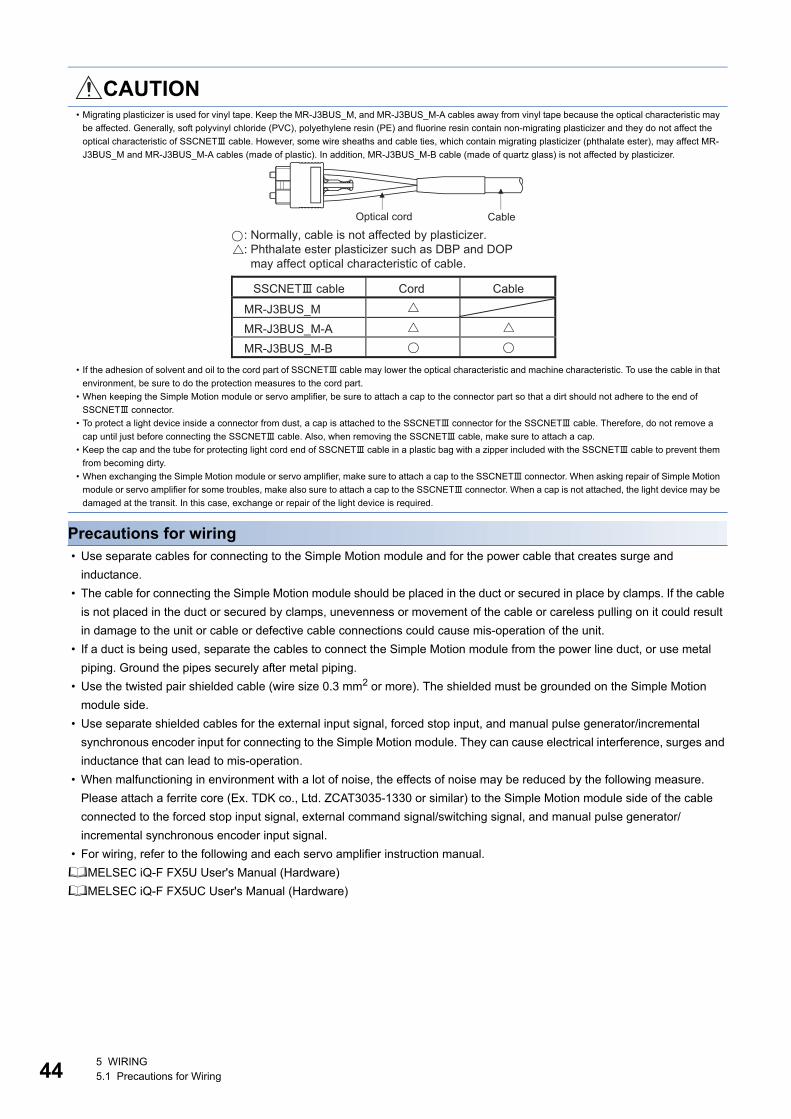
44
Precautions for wiring • Use separate cables for connecting to the Simple Motion module and for the power cable that creates surge and
inductance.
• The cable for connecting the Simple Motion module should be placed in the duct or secured in place by clamps. If the cable
is not placed in the duct or secured by clamps, unevenness or movement of the cable or careless pulling on it could result
in damage to the unit or cable or defective cable connections could cause mis-operation of the unit.
• If a duct is being used, separate the cables to connect the Simple Motion module from the power line duct, or use metal
piping. Ground the pipes securely after metal piping.
• Use the twisted pair shielded cable (wire size 0.3 mm2 or more). The shielded must be grounded on the Simple Motion
module side.
• Use separate shielded cables for the external input signal, forced stop input, and manual pulse generator/incremental
synchronous encoder input for connecting to the Simple Motion module. They can cause electrical interference, surges and
inductance that can lead to mis-operation.
• When malfunctioning in environment with a lot of noise, the effects of noise may be reduced by the following measure.
Please attach a ferrite core (Ex. TDK co., Ltd. ZCAT3035-1330 or similar) to the Simple Motion module side of the cable
connected to the forced stop input signal, external command signal/switching signal, and manual pulse generator/
incremental synchronous encoder input signal.
• For wiring, refer to the following and each servo amplifier instruction manual.
MELSEC iQ-F FX5U User's Manual (Hardware)
MELSEC iQ-F FX5UC User's Manual (Hardware)
• Migrating plasticizer is used for vinyl tape. Keep the MR-J3BUS_M, and MR-J3BUS_M-A cables away from vinyl tape because the optical characteristic may
be affected. Generally, soft polyvinyl chloride (PVC), polyethylene resin (PE) and fluorine resin contain non-migrating plasticizer and they do not affect the
optical characteristic of SSCNET cable. However, some wire sheaths and cable ties, which contain migrating plasticizer (phthalate ester), may affect MR-
J3BUS_M and MR-J3BUS_M-A cables (made of plastic). In addition, MR-J3BUS_M-B cable (made of quartz glass) is not affected by plasticizer.
• If the adhesion of solvent and oil to the cord part of SSCNET cable may lower the optical characteristic and machine characteristic. To use the cable in that
environment, be sure to do the protection measures to the cord part.
• When keeping the Simple Motion module or servo amplifier, be sure to attach a cap to the connector part so that a dirt should not adhere to the end of
SSCNET connector.
• To protect a light device inside a connector from dust, a cap is attached to the SSCNET connector for the SSCNET cable. Therefore, do not remove a
cap until just before connecting the SSCNET cable. Also, when removing the SSCNET cable, make sure to attach a cap.
• Keep the cap and the tube for protecting light cord end of SSCNET cable in a plastic bag with a zipper included with the SSCNET cable to prevent them
from becoming dirty.
• When exchanging the Simple Motion module or servo amplifier, make sure to attach a cap to the SSCNET connector. When asking repair of Simple Motion
module or servo amplifier for some troubles, make also sure to attach a cap to the SSCNET connector. When a cap is not attached, the light device may be
damaged at the transit. In this case, exchange or repair of the light device is required.
CAUTION
CableOptical cord
SSCNET cable Cord Cable
MR-J3BUS_MMR-J3BUS_M-AMR-J3BUS_M-B
: Normally, cable is not affected by plasticizer. : Phthalate ester plasticizer such as DBP and DOP may affect optical characteristic of cable.
5 WIRING5.1 Precautions for Wiring
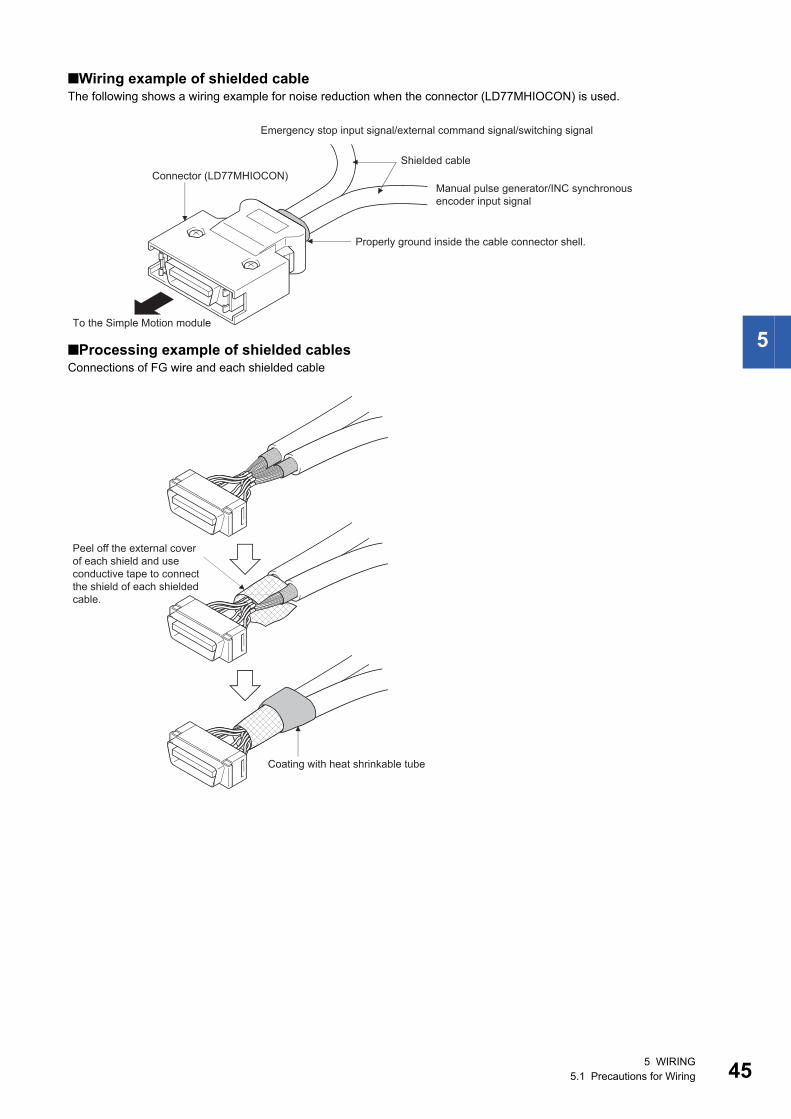
5
Wiring example of shielded cableThe following shows a wiring example for noise reduction when the connector (LD77MHIOCON) is used.
Processing example of shielded cablesConnections of FG wire and each shielded cable
To the Simple Motion module
Connector (LD77MHIOCON)
Properly ground inside the cable connector shell.
Shielded cable
Emergency stop input signal/external command signal/switching signal
Manual pulse generator/INC synchronous encoder input signal
Coating with heat shrinkable tube
Peel off the external cover of each shield and use conductive tape to connect the shield of each shielded cable.
5 WIRING5.1 Precautions for Wiring 45
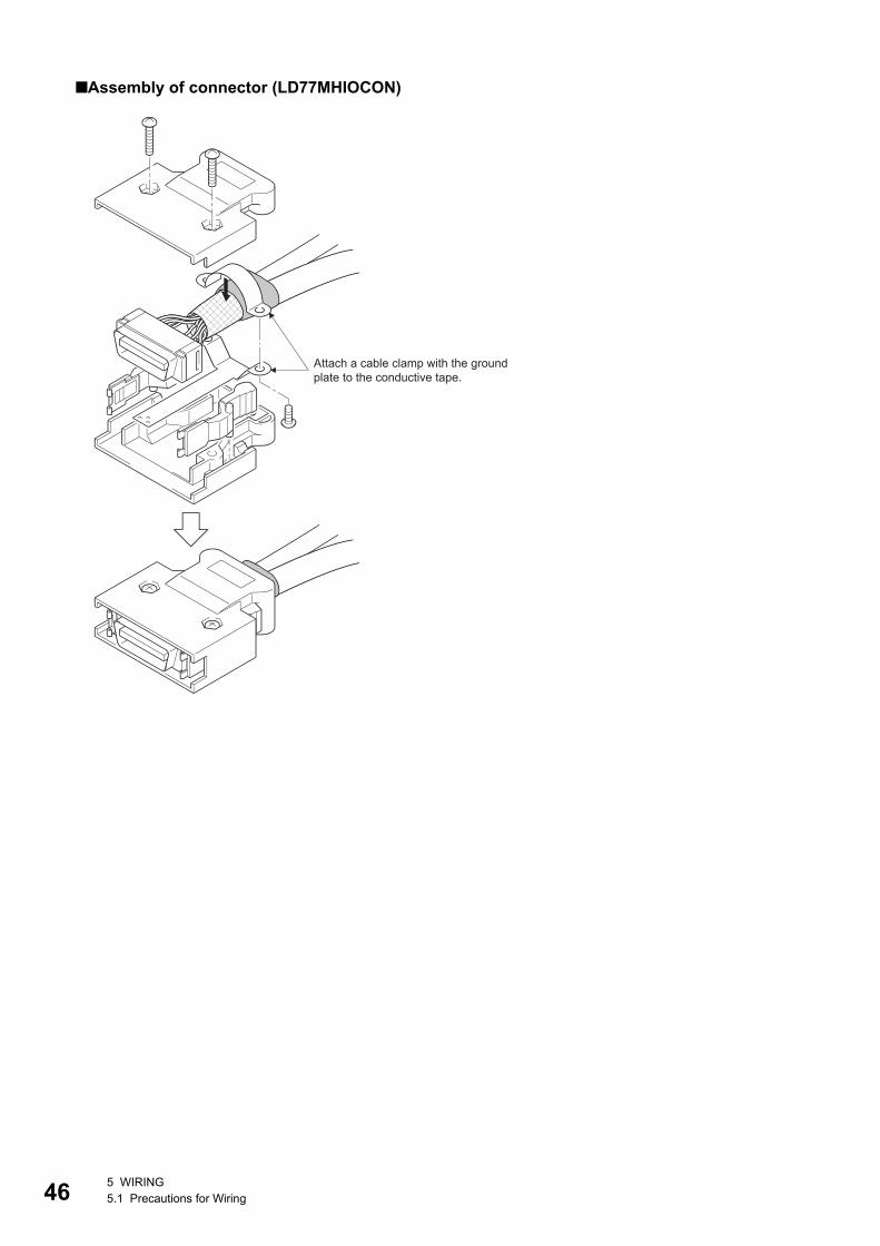
46
Assembly of connector (LD77MHIOCON)
Attach a cable clamp with the ground plate to the conductive tape.
5 WIRING5.1 Precautions for Wiring
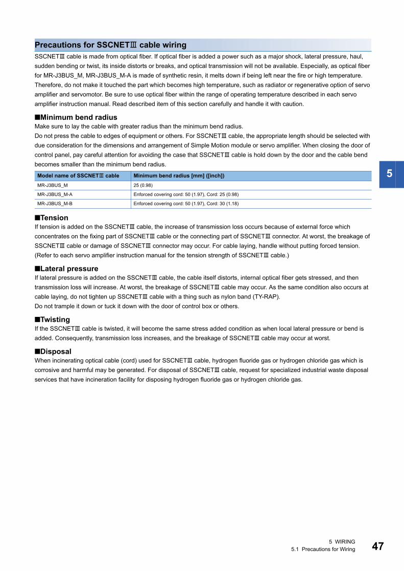
5
Precautions for SSCNET cable wiringSSCNET cable is made from optical fiber. If optical fiber is added a power such as a major shock, lateral pressure, haul,
sudden bending or twist, its inside distorts or breaks, and optical transmission will not be available. Especially, as optical fiber
for MR-J3BUS_M, MR-J3BUS_M-A is made of synthetic resin, it melts down if being left near the fire or high temperature.
Therefore, do not make it touched the part which becomes high temperature, such as radiator or regenerative option of servo
amplifier and servomotor. Be sure to use optical fiber within the range of operating temperature described in each servo
amplifier instruction manual. Read described item of this section carefully and handle it with caution.
Minimum bend radiusMake sure to lay the cable with greater radius than the minimum bend radius.
Do not press the cable to edges of equipment or others. For SSCNET cable, the appropriate length should be selected with
due consideration for the dimensions and arrangement of Simple Motion module or servo amplifier. When closing the door of
control panel, pay careful attention for avoiding the case that SSCNET cable is hold down by the door and the cable bend
becomes smaller than the minimum bend radius.
TensionIf tension is added on the SSCNET cable, the increase of transmission loss occurs because of external force which
concentrates on the fixing part of SSCNET cable or the connecting part of SSCNET connector. At worst, the breakage of
SSCNET cable or damage of SSCNET connector may occur. For cable laying, handle without putting forced tension.
(Refer to each servo amplifier instruction manual for the tension strength of SSCNET cable.)
Lateral pressureIf lateral pressure is added on the SSCNET cable, the cable itself distorts, internal optical fiber gets stressed, and then
transmission loss will increase. At worst, the breakage of SSCNET cable may occur. As the same condition also occurs at
cable laying, do not tighten up SSCNET cable with a thing such as nylon band (TY-RAP).
Do not trample it down or tuck it down with the door of control box or others.
TwistingIf the SSCNET cable is twisted, it will become the same stress added condition as when local lateral pressure or bend is
added. Consequently, transmission loss increases, and the breakage of SSCNET cable may occur at worst.
DisposalWhen incinerating optical cable (cord) used for SSCNET cable, hydrogen fluoride gas or hydrogen chloride gas which is
corrosive and harmful may be generated. For disposal of SSCNET cable, request for specialized industrial waste disposal
services that have incineration facility for disposing hydrogen fluoride gas or hydrogen chloride gas.
Model name of SSCNET cable Minimum bend radius [mm] ([inch])
MR-J3BUS_M 25 (0.98)
MR-J3BUS_M-A Enforced covering cord: 50 (1.97), Cord: 25 (0.98)
MR-J3BUS_M-B Enforced covering cord: 50 (1.97), Cord: 30 (1.18)
5 WIRING5.1 Precautions for Wiring 47
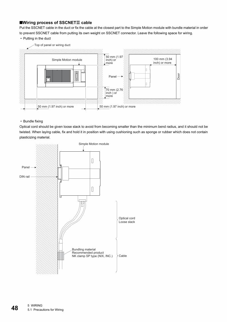
48
Wiring process of SSCNET cablePut the SSCNET cable in the duct or fix the cable at the closest part to the Simple Motion module with bundle material in order
to prevent SSCNET cable from putting its own weight on SSCNET connector. Leave the following space for wiring.
• Putting in the duct
• Bundle fixing
Optical cord should be given loose slack to avoid from becoming smaller than the minimum bend radius, and it should not be
twisted. When laying cable, fix and hold it in position with using cushioning such as sponge or rubber which does not contain
plasticizing material.
Panel
Doo
r
Top of panel or wiring duct
50 mm (1.97 inch) or more50 mm (1.97 inch) or more
Simple Motion module50 mm (1.97 inch) or more
70 mm (2.76 inch ) or more
100 mm (3.94 inch) or more
Bundling material
Simple Motion module
Panel
DIN rail
Cable
Optical cord Loose slack
NK clamp SP type (NIX, INC.)Recommended product
5 WIRING5.1 Precautions for Wiring
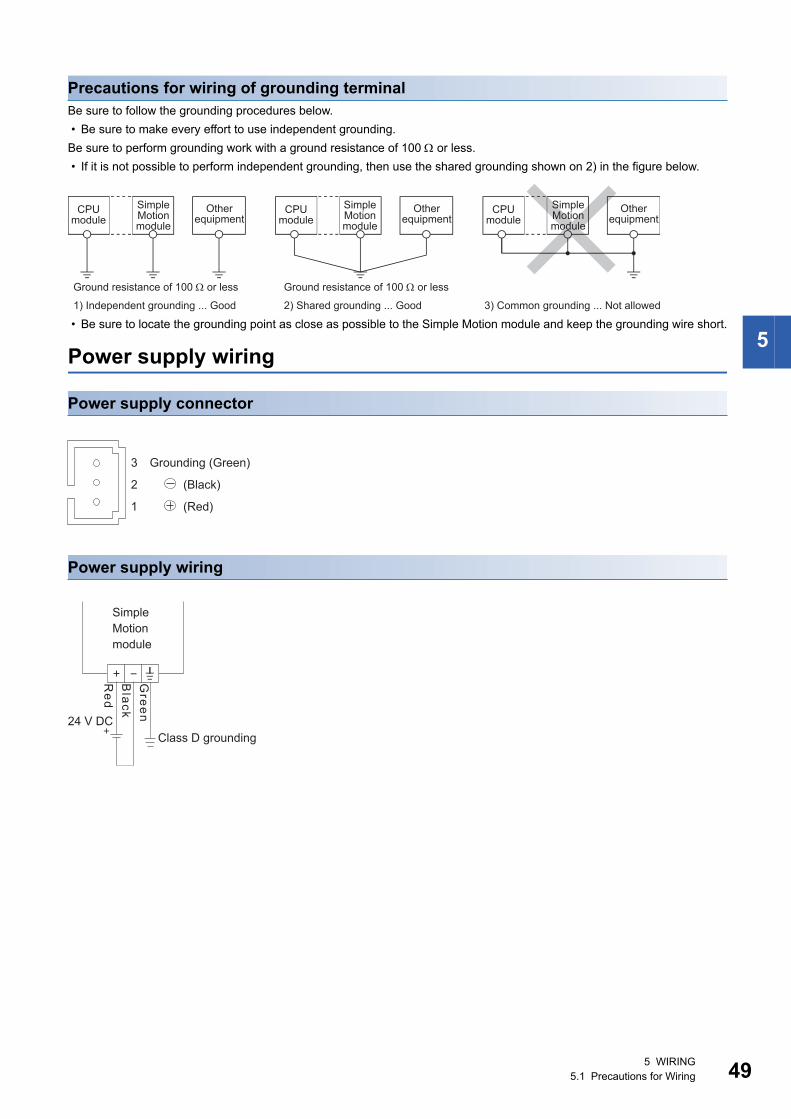
5
Precautions for wiring of grounding terminalBe sure to follow the grounding procedures below.
• Be sure to make every effort to use independent grounding.
Be sure to perform grounding work with a ground resistance of 100 or less.
• If it is not possible to perform independent grounding, then use the shared grounding shown on 2) in the figure below.
• Be sure to locate the grounding point as close as possible to the Simple Motion module and keep the grounding wire short.
Power supply wiring
Power supply connector
Power supply wiring
2) Shared grounding ... Good 3) Common grounding ... Not allowed1) Independent grounding ... Good
Ground resistance of 100 or less Ground resistance of 100 or less
CPU module
CPU module
CPU module
SimpleMotionmodule
SimpleMotionmodule
SimpleMotionmodule
Other equipment
Other equipment
Other equipment
Grounding (Green)
(Black)
(Red)
3
2
1
Class D grounding24 V DC
Green
Simple Motion module
Red
Black
5 WIRING5.1 Precautions for Wiring 49
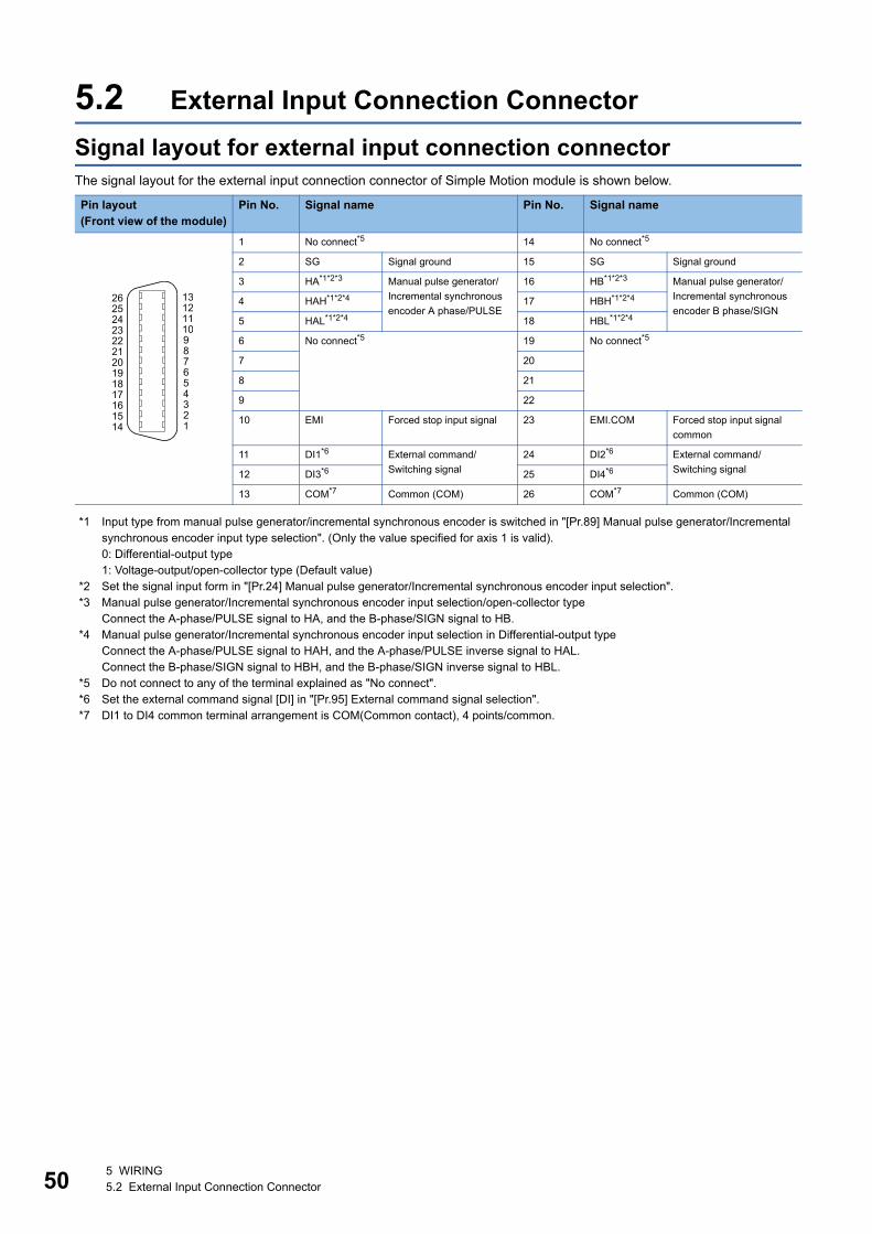
50
5.2 External Input Connection Connector
Signal layout for external input connection connectorThe signal layout for the external input connection connector of Simple Motion module is shown below.
*1 Input type from manual pulse generator/incremental synchronous encoder is switched in "[Pr.89] Manual pulse generator/Incremental synchronous encoder input type selection". (Only the value specified for axis 1 is valid).0: Differential-output type1: Voltage-output/open-collector type (Default value)
*2 Set the signal input form in "[Pr.24] Manual pulse generator/Incremental synchronous encoder input selection".*3 Manual pulse generator/Incremental synchronous encoder input selection/open-collector type
Connect the A-phase/PULSE signal to HA, and the B-phase/SIGN signal to HB.*4 Manual pulse generator/Incremental synchronous encoder input selection in Differential-output type
Connect the A-phase/PULSE signal to HAH, and the A-phase/PULSE inverse signal to HAL.Connect the B-phase/SIGN signal to HBH, and the B-phase/SIGN inverse signal to HBL.
*5 Do not connect to any of the terminal explained as "No connect".*6 Set the external command signal [DI] in "[Pr.95] External command signal selection".*7 DI1 to DI4 common terminal arrangement is COM(Common contact), 4 points/common.
Pin layout(Front view of the module)
Pin No. Signal name Pin No. Signal name
1 No connect*5 14 No connect*5
2 SG Signal ground 15 SG Signal ground
3 HA*1*2*3 Manual pulse generator/
Incremental synchronous
encoder A phase/PULSE
16 HB*1*2*3 Manual pulse generator/
Incremental synchronous
encoder B phase/SIGN4 HAH*1*2*4 17 HBH*1*2*4
5 HAL*1*2*4 18 HBL*1*2*4
6 No connect*5 19 No connect*5
7 20
8 21
9 22
10 EMI Forced stop input signal 23 EMI.COM Forced stop input signal
common
11 DI1*6 External command/
Switching signal
24 DI2*6 External command/
Switching signal12 DI3*6 25 DI4*6
13 COM*7 Common (COM) 26 COM*7 Common (COM)
26
1516171819202122232425
13
123456789101112
14
5 WIRING5.2 External Input Connection Connector
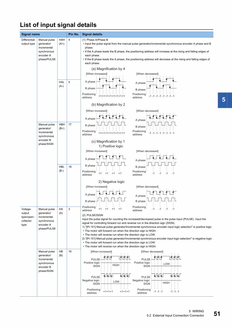
5
List of input signal detailsSignal name Pin No. Signal details
Differential-
output type
Manual pulse
generator/
Incremental
synchronous
encoder A
phase/PULSE
HAH
(A+)
4 (1) Phase A/Phase B
• Input the pulse signal from the manual pulse generator/incremental synchronous encoder A phase and B
phase.
• If the A phase leads the B phase, the positioning address will increase at the rising and falling edges of
each phase.
• If the B phase leads the A phase, the positioning address will decrease at the rising and falling edges of
each phase.
(2) PULSE/SIGN
Input the pulse signal for counting the increased/decreased pulse in the pulse input (PULSE). Input the
signal for controlling forward run and reverse run in the direction sign (SIGN).
1) "[Pr.151] Manual pulse generator/Incremental synchronous encoder input logic selection" is positive logic
• The motor will forward run when the direction sign is HIGH.
• The motor will reverse run when the direction sign is LOW.
2) "[Pr.151] Manual pulse generator/Incremental synchronous encoder input logic selection" is negative logic
• The motor will forward run when the direction sign is LOW.
• The motor will reverse run when the direction sign is HIGH.
HAL
(A-)
5
Manual pulse
generator/
Incremental
synchronous
encoder B
phase/SIGN
HBH
(B+)
17
HBL
(B-)
18
Voltage-
output
type/open-
collector
type
Manual pulse
generator/
Incremental
synchronous
encoder A
phase/PULSE
HA
(A)
3
Manual pulse
generator/
Incremental
synchronous
encoder B
phase/SIGN
HB
(B)
16
(a) Magnification by 4
Positioningaddress
A phase
[When increased] [When decreased]
+1+1+1+1+1+1+1+1
B phase
A phase
B phase
-1 -1 -1 -1 -1 -1 -1 -1Positioningaddress
(b) Magnification by 2
Positioningaddress
A phase
[When increased] [When decreased]
+1+1+1+1+1+1+1+1
B phase
A phase
B phase
-1 -1 -1 -1 -1 -1 -1 -1Positioningaddress
(c) Magnification by 11) Positive logic
Positioningaddress
A phase
[When increased] [When decreased]
+1 +1 +1 +1
B phase
A phase
B phase
-1 -1 -1 -1Positioningaddress
2) Negative logic
Positioningaddress
A phase
[When increased] [When decreased]
+1 +1 +1 +1
B phase
A phase
B phase
-1 -1 -1 -1Positioningaddress
Positioningaddress +1+1+1 +1+1+1 -1 -1 -1 -1 -1 -1
Positioningaddress
PULSE
SIGN
PULSE
SIGN
LOW
Negative logic
[When increased] [When decreased]
PULSE
SIGN
LOW
PULSE
SIGN
HIGH
Positive logicHIGH
Negative logic
Positive logic
5 WIRING5.2 External Input Connection Connector 51
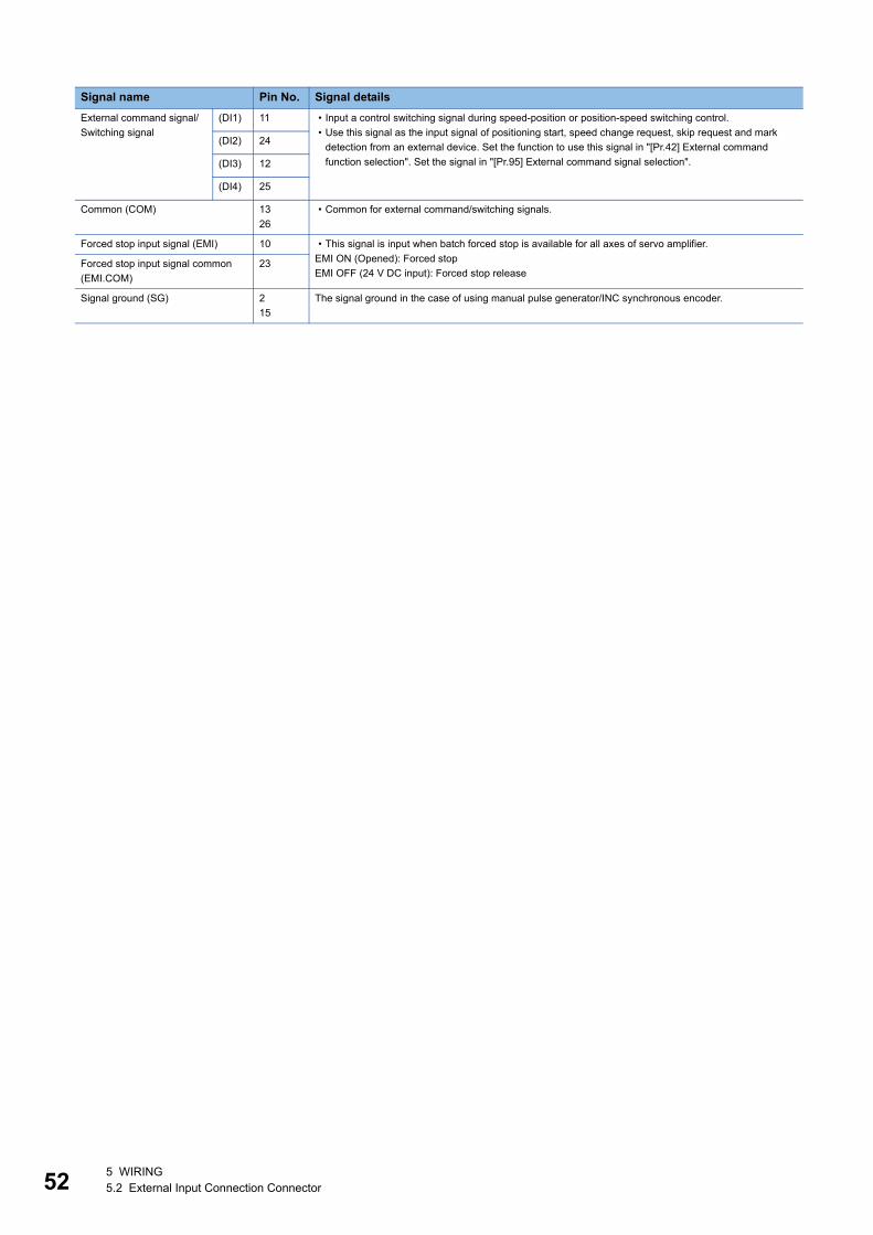
52
Signal name Pin No. Signal details
External command signal/
Switching signal
(DI1) 11 • Input a control switching signal during speed-position or position-speed switching control.
• Use this signal as the input signal of positioning start, speed change request, skip request and mark
detection from an external device. Set the function to use this signal in "[Pr.42] External command
function selection". Set the signal in "[Pr.95] External command signal selection".
(DI2) 24
(DI3) 12
(DI4) 25
Common (COM) 13
26
• Common for external command/switching signals.
Forced stop input signal (EMI) 10 • This signal is input when batch forced stop is available for all axes of servo amplifier.
EMI ON (Opened): Forced stop
EMI OFF (24 V DC input): Forced stop releaseForced stop input signal common
(EMI.COM)
23
Signal ground (SG) 2
15
The signal ground in the case of using manual pulse generator/INC synchronous encoder.
5 WIRING5.2 External Input Connection Connector
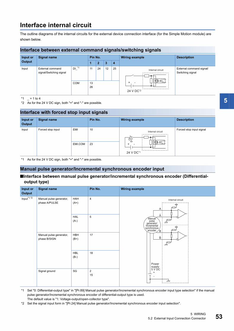
5
Interface internal circuitThe outline diagrams of the internal circuits for the external device connection interface (for the Simple Motion module) are
shown below.
Interface between external command signals/switching signals
*1 _ = 1 to 4*2 As for the 24 V DC sign, both "+" and "-" are possible.
Interface with forced stop input signals
*1 As for the 24 V DC sign, both "+" and "-" are possible.
Manual pulse generator/Incremental synchronous encoder input
Interface between manual pulse generator/incremental synchronous encoder (Differential-output type)
*1 Set "0: Differential-output type" in "[Pr.89] Manual pulse generator/Incremental synchronous encoder input type selection" if the manual pulse generator/Incremental synchronous encoder of differential-output type is used. The default value is "1: Voltage-output/open-collector type".
*2 Set the signal input form in "[Pr.24] Manual pulse generator/Incremental synchronous encoder input selection".
Input or Output
Signal name Pin No. Wiring example Description
1 2 3 4
Input External command
signal/Switching signal
DI_*1 11 24 12 25 External command signal/
Switching signal
COM 13
26
Input or Output
Signal name Pin No. Wiring example Description
Input Forced stop input EMI 10 Forced stop input signal
EMI.COM 23
Input or Output
Signal name Pin No. Wiring example
Input*1,*2 Manual pulse generator,
phase A/PULSE
HAH
(A+)
4
HAL
(A-)
5
Manual pulse generator,
phase B/SIGN
HBH
(B+)
17
HBL
(B-)
18
Signal ground SG 2
15
+ -
24 V DC*2
Internal circuit
+ -
24 V DC*1
Internal circuit
-+
A
A
B
B
Manual pulse
generator/ Incremental synchronous
encoder
Internal circuit
Power supply 5 V DC
5 WIRING5.2 External Input Connection Connector 53
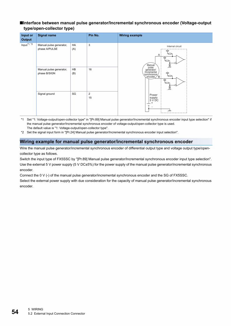
54
Interface between manual pulse generator/Incremental synchronous encoder (Voltage-output type/open-collector type)
*1 Set "1: Voltage-output/open-collector type" in "[Pr.89] Manual pulse generator/Incremental synchronous encoder input type selection" if the manual pulse generator/Incremental synchronous encoder of voltage-output/open-collector type is used.The default value is "1: Voltage-output/open-collector type".
*2 Set the signal input form in "[Pr.24] Manual pulse generator/Incremental synchronous encoder input selection".
Wiring example for manual pulse generator/incremental synchronous encoderWire the manual pulse generator/incremental synchronous encoder of differential output type and voltage output type/open-
collector type as follows.
Switch the input type of FX5SSC by "[Pr.89] Manual pulse generator/Incremental synchronous encoder input type selection".
Use the external 5 V power supply (5 V DC±5%) for the power supply of the manual pulse generator/incremental synchronous
encoder.
Connect the 0 V (-) of the manual pulse generator/incremental synchronous encoder and the SG of FX5SSC.
Select the external power supply with due consideration for the capacity of manual pulse generator/incremental synchronous
encoder.
Input or Output
Signal name Pin No. Wiring example
Input*1, *2 Manual pulse generator,
phase A/PULSE
HA
(A)
3
Manual pulse generator,
phase B/SIGN
HB
(B)
16
Signal ground SG 2
15
A
B
-+
Manual pulse
generator/ Incremental synchronous
encoder
Power supply 5 V DC
Internal circuit
5 WIRING5.2 External Input Connection Connector
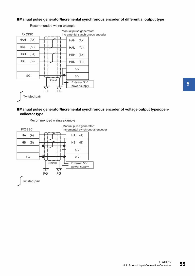
5
Manual pulse generator/Incremental synchronous encoder of differential output type
Manual pulse generator/Incremental synchronous encoder of voltage output type/open-collector type
FX5SSC
HAH (A+)
HAL (A-)
HBH (B+)
HBL (B-)
HAH (A+)
HAL (A-)
HBH (B+)
HBL (B-)
External 5 Vpower supply
5 V
0 V
Recommended wiring example
FGFGTwisted pair
Shield
Manual pulse generator/Incremental synchronous encoder
SG
External 5 Vpower supply
FGFG
HA (A)
HB (B)
SG
HA (A)
HB (B)
5 V
0 V
FX5SSC
Recommended wiring example
Manual pulse generator/Incremental synchronous encoder
Shield
Twisted pair
5 WIRING5.2 External Input Connection Connector 55
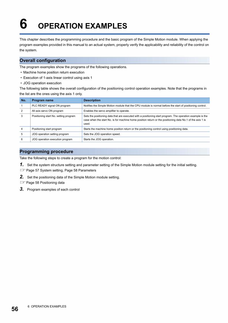
56
6 OPERATION EXAMPLES
This chapter describes the programming procedure and the basic program of the Simple Motion module. When applying the
program examples provided in this manual to an actual system, properly verify the applicability and reliability of the control on
the system.
Overall configurationThe program examples show the programs of the following operations.
• Machine home position return execution
• Execution of 1-axis linear control using axis 1
• JOG operation execution
The following table shows the overall configuration of the positioning control operation examples. Note that the programs in
the list are the ones using the axis 1 only.
Programming procedureTake the following steps to create a program for the motion control:
1. Set the system structure setting and parameter setting of the Simple Motion module setting for the initial setting.
Page 57 System setting, Page 58 Parameters
2. Set the positioning data of the Simple Motion module setting.
Page 58 Positioning data
3. Program examples of each control
No. Program name Description
1 PLC READY signal ON program Notifies the Simple Motion module that the CPU module is normal before the start of positioning control.
2 All axis servo ON program Enables the servo amplifier to operate.
3 Positioning start No. setting program Sets the positioning data that are executed with a positioning start program. The operation example is the
case when the start No. is for machine home position return or the positioning data No.1 of the axis 1 is
used.
4 Positioning start program Starts the machine home position return or the positioning control using positioning data.
5 JOG operation setting program Sets the JOG operation speed.
6 JOG operation execution program Starts the JOG operation.
6 OPERATION EXAMPLES
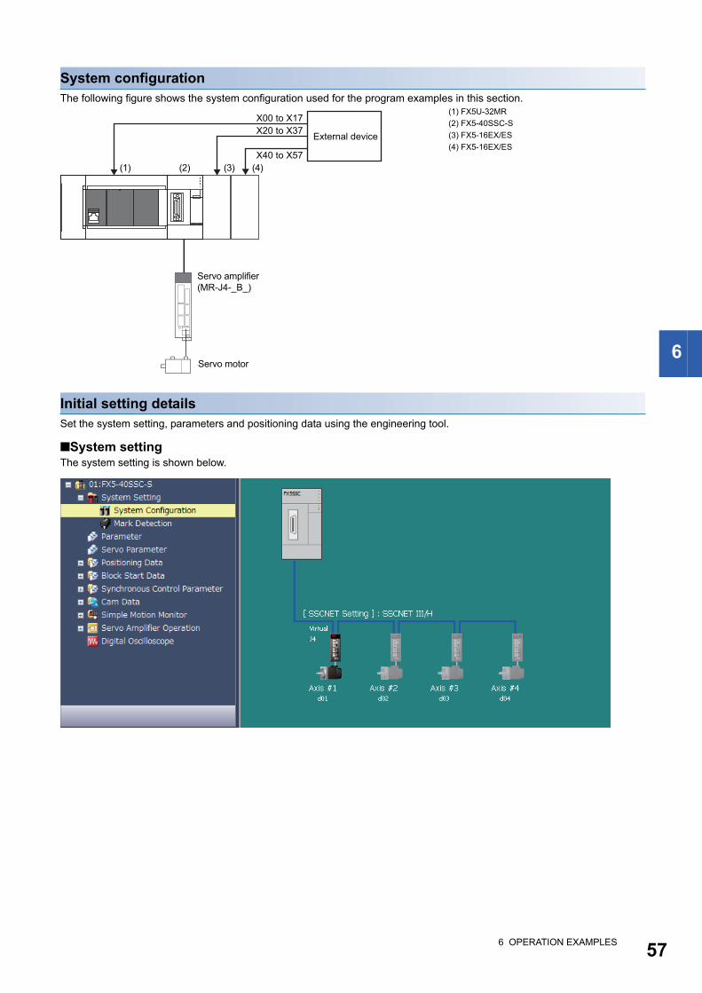
6
System configurationThe following figure shows the system configuration used for the program examples in this section.
Initial setting detailsSet the system setting, parameters and positioning data using the engineering tool.
System settingThe system setting is shown below.
(1) FX5U-32MR
(2) FX5-40SSC-S
(3) FX5-16EX/ES
(4) FX5-16EX/ES
(1) (2) (3) (4)
Servo amplifier(MR-J4-_B_)
Servo motor
External device
X00 to X17X20 to X37
X40 to X57
6 OPERATION EXAMPLES 57
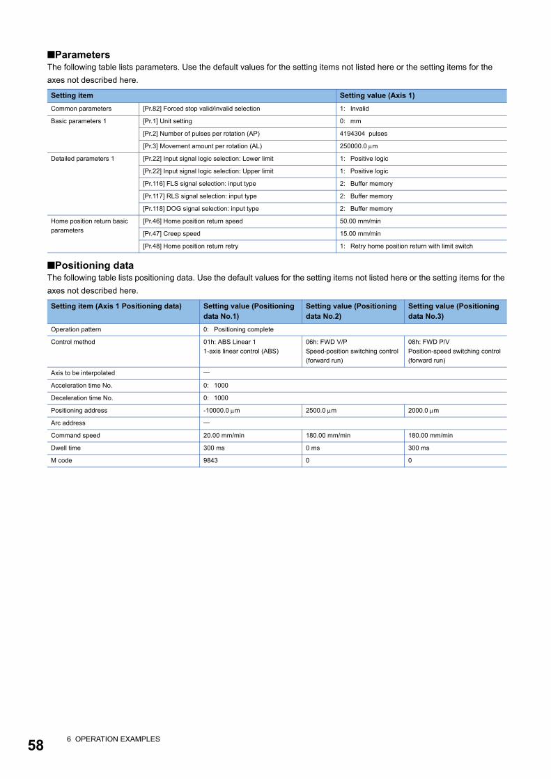
58
ParametersThe following table lists parameters. Use the default values for the setting items not listed here or the setting items for the
axes not described here.
Positioning dataThe following table lists positioning data. Use the default values for the setting items not listed here or the setting items for the
axes not described here.
Setting item Setting value (Axis 1)
Common parameters [Pr.82] Forced stop valid/invalid selection 1: Invalid
Basic parameters 1 [Pr.1] Unit setting 0: mm
[Pr.2] Number of pulses per rotation (AP) 4194304 pulses
[Pr.3] Movement amount per rotation (AL) 250000.0 m
Detailed parameters 1 [Pr.22] Input signal logic selection: Lower limit 1: Positive logic
[Pr.22] Input signal logic selection: Upper limit 1: Positive logic
[Pr.116] FLS signal selection: input type 2: Buffer memory
[Pr.117] RLS signal selection: input type 2: Buffer memory
[Pr.118] DOG signal selection: input type 2: Buffer memory
Home position return basic
parameters
[Pr.46] Home position return speed 50.00 mm/min
[Pr.47] Creep speed 15.00 mm/min
[Pr.48] Home position return retry 1: Retry home position return with limit switch
Setting item (Axis 1 Positioning data) Setting value (Positioning data No.1)
Setting value (Positioning data No.2)
Setting value (Positioning data No.3)
Operation pattern 0: Positioning complete
Control method 01h: ABS Linear 1
1-axis linear control (ABS)
06h: FWD V/P
Speed-position switching control
(forward run)
08h: FWD P/V
Position-speed switching control
(forward run)
Axis to be interpolated
Acceleration time No. 0: 1000
Deceleration time No. 0: 1000
Positioning address -10000.0 m 2500.0 m 2000.0 m
Arc address
Command speed 20.00 mm/min 180.00 mm/min 180.00 mm/min
Dwell time 300 ms 0 ms 300 ms
M code 9843 0 0
6 OPERATION EXAMPLES
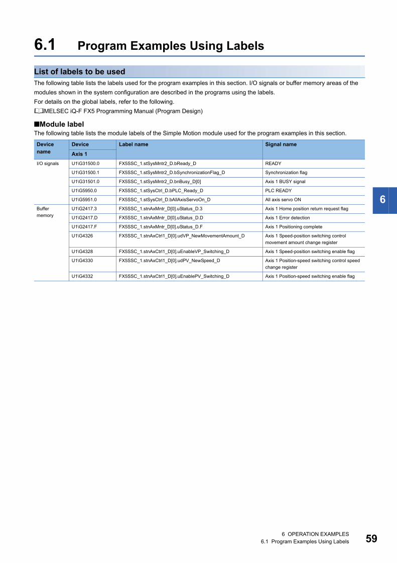
6
6.1 Program Examples Using Labels
List of labels to be usedThe following table lists the labels used for the program examples in this section. I/O signals or buffer memory areas of the
modules shown in the system configuration are described in the programs using the labels.
For details on the global labels, refer to the following.
MELSEC iQ-F FX5 Programming Manual (Program Design)
Module labelThe following table lists the module labels of the Simple Motion module used for the program examples in this section.
Device name
Device Label name Signal name
Axis 1
I/O signals U1\G31500.0 FX5SSC_1.stSysMntr2_D.bReady_D READY
U1\G31500.1 FX5SSC_1.stSysMntr2_D.bSynchronizationFlag_D Synchronization flag
U1\G31501.0 FX5SSC_1.stSysMntr2_D.bnBusy_D[0] Axis 1 BUSY signal
U1\G5950.0 FX5SSC_1.stSysCtrl_D.bPLC_Ready_D PLC READY
U1\G5951.0 FX5SSC_1.stSysCtrl_D.bAllAxisServoOn_D All axis servo ON
Buffer
memory
U1\G2417.3 FX5SSC_1.stnAxMntr_D[0].uStatus_D.3 Axis 1 Home position return request flag
U1\G2417.D FX5SSC_1.stnAxMntr_D[0].uStatus_D.D Axis 1 Error detection
U1\G2417.F FX5SSC_1.stnAxMntr_D[0].uStatus_D.F Axis 1 Positioning complete
U1\G4326 FX5SSC_1.stnAxCtrl1_D[0].udVP_NewMovementAmount_D Axis 1 Speed-position switching control
movement amount change register
U1\G4328 FX5SSC_1.stnAxCtrl1_D[0].uEnableVP_Switching_D Axis 1 Speed-position switching enable flag
U1\G4330 FX5SSC_1.stnAxCtrl1_D[0].udPV_NewSpeed_D Axis 1 Position-speed switching control speed
change register
U1\G4332 FX5SSC_1.stnAxCtrl1_D[0].uEnablePV_Switching_D Axis 1 Position-speed switching enable flag
6 OPERATION EXAMPLES6.1 Program Examples Using Labels 59
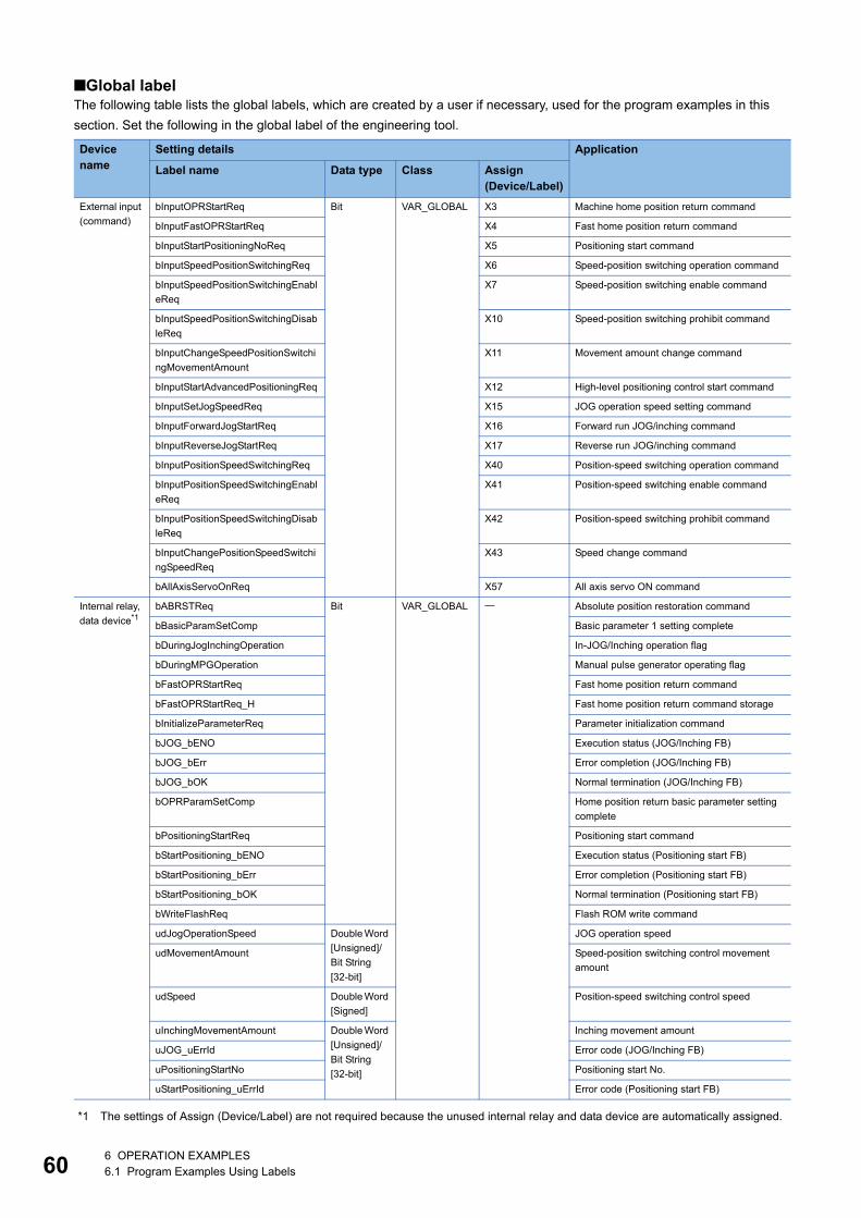
60
Global labelThe following table lists the global labels, which are created by a user if necessary, used for the program examples in this
section. Set the following in the global label of the engineering tool.
*1 The settings of Assign (Device/Label) are not required because the unused internal relay and data device are automatically assigned.
Device name
Setting details Application
Label name Data type Class Assign (Device/Label)
External input
(command)
bInputOPRStartReq Bit VAR_GLOBAL X3 Machine home position return command
bInputFastOPRStartReq X4 Fast home position return command
bInputStartPositioningNoReq X5 Positioning start command
bInputSpeedPositionSwitchingReq X6 Speed-position switching operation command
bInputSpeedPositionSwitchingEnabl
eReq
X7 Speed-position switching enable command
bInputSpeedPositionSwitchingDisab
leReq
X10 Speed-position switching prohibit command
bInputChangeSpeedPositionSwitchi
ngMovementAmount
X11 Movement amount change command
bInputStartAdvancedPositioningReq X12 High-level positioning control start command
bInputSetJogSpeedReq X15 JOG operation speed setting command
bInputForwardJogStartReq X16 Forward run JOG/inching command
bInputReverseJogStartReq X17 Reverse run JOG/inching command
bInputPositionSpeedSwitchingReq X40 Position-speed switching operation command
bInputPositionSpeedSwitchingEnabl
eReq
X41 Position-speed switching enable command
bInputPositionSpeedSwitchingDisab
leReq
X42 Position-speed switching prohibit command
bInputChangePositionSpeedSwitchi
ngSpeedReq
X43 Speed change command
bAllAxisServoOnReq X57 All axis servo ON command
Internal relay,
data device*1bABRSTReq Bit VAR_GLOBAL Absolute position restoration command
bBasicParamSetComp Basic parameter 1 setting complete
bDuringJogInchingOperation In-JOG/Inching operation flag
bDuringMPGOperation Manual pulse generator operating flag
bFastOPRStartReq Fast home position return command
bFastOPRStartReq_H Fast home position return command storage
bInitializeParameterReq Parameter initialization command
bJOG_bENO Execution status (JOG/Inching FB)
bJOG_bErr Error completion (JOG/Inching FB)
bJOG_bOK Normal termination (JOG/Inching FB)
bOPRParamSetComp Home position return basic parameter setting
complete
bPositioningStartReq Positioning start command
bStartPositioning_bENO Execution status (Positioning start FB)
bStartPositioning_bErr Error completion (Positioning start FB)
bStartPositioning_bOK Normal termination (Positioning start FB)
bWriteFlashReq Flash ROM write command
udJogOperationSpeed Double Word
[Unsigned]/
Bit String
[32-bit]
JOG operation speed
udMovementAmount Speed-position switching control movement
amount
udSpeed Double Word
[Signed]
Position-speed switching control speed
uInchingMovementAmount Double Word
[Unsigned]/
Bit String
[32-bit]
Inching movement amount
uJOG_uErrId Error code (JOG/Inching FB)
uPositioningStartNo Positioning start No.
uStartPositioning_uErrId Error code (Positioning start FB)
6 OPERATION EXAMPLES6.1 Program Examples Using Labels

6
Program example
The program examples use the module function blocks (FBs) and module labels displayed in "Module POU".
For details on module function blocks, refer to the following.
MELSEC iQ-F FX5 Simple Motion Module Function Block Reference
PLC READY signal ON program
All axis servo ON program
6 OPERATION EXAMPLES6.1 Program Examples Using Labels 61

62
Positioning start No. setting program
6 OPERATION EXAMPLES6.1 Program Examples Using Labels
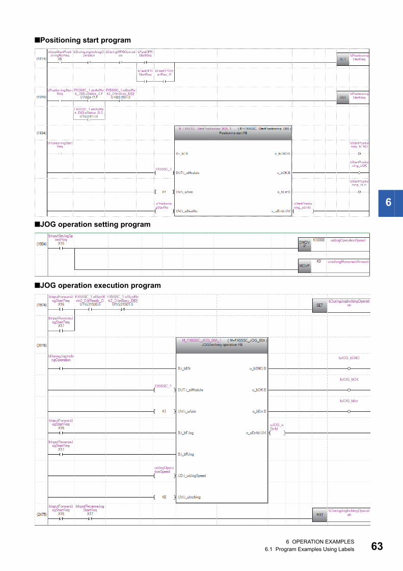
6
Positioning start program
JOG operation setting program
JOG operation execution program
6 OPERATION EXAMPLES6.1 Program Examples Using Labels 63
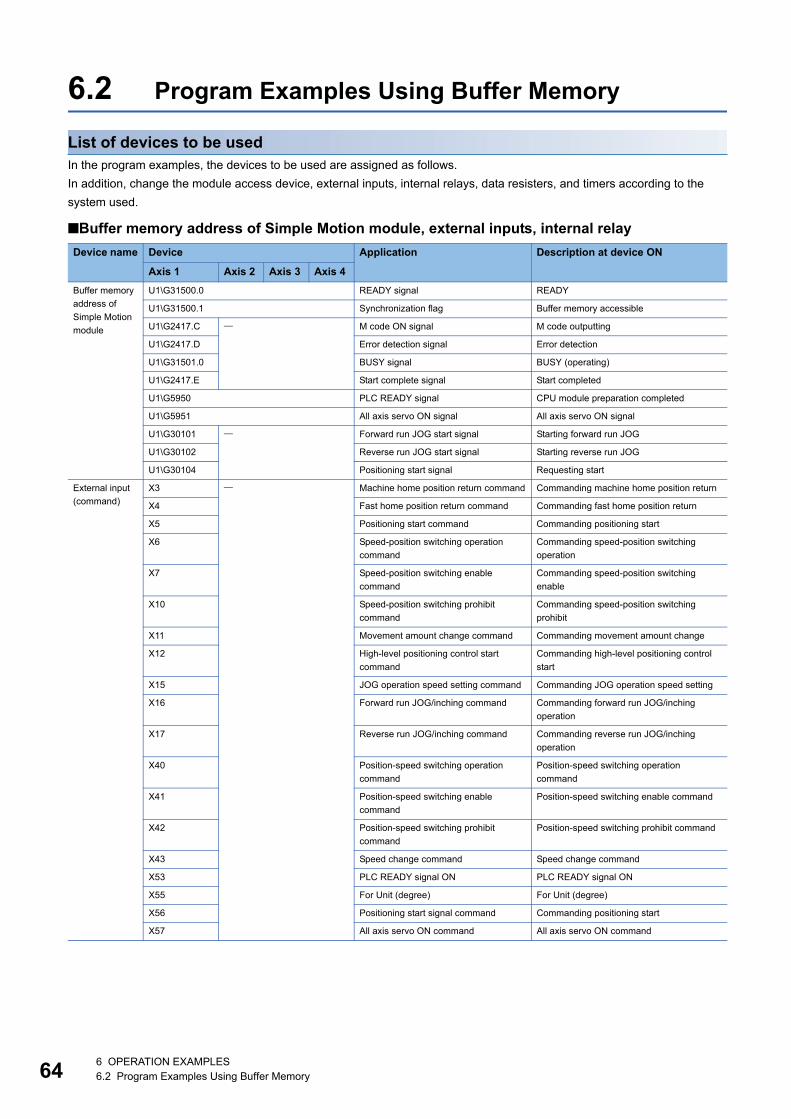
64
6.2 Program Examples Using Buffer Memory
List of devices to be usedIn the program examples, the devices to be used are assigned as follows.
In addition, change the module access device, external inputs, internal relays, data resisters, and timers according to the
system used.
Buffer memory address of Simple Motion module, external inputs, internal relay
Device name Device Application Description at device ON
Axis 1 Axis 2 Axis 3 Axis 4
Buffer memory
address of
Simple Motion
module
U1\G31500.0 READY signal READY
U1\G31500.1 Synchronization flag Buffer memory accessible
U1\G2417.C M code ON signal M code outputting
U1\G2417.D Error detection signal Error detection
U1\G31501.0 BUSY signal BUSY (operating)
U1\G2417.E Start complete signal Start completed
U1\G5950 PLC READY signal CPU module preparation completed
U1\G5951 All axis servo ON signal All axis servo ON signal
U1\G30101 Forward run JOG start signal Starting forward run JOG
U1\G30102 Reverse run JOG start signal Starting reverse run JOG
U1\G30104 Positioning start signal Requesting start
External input
(command)
X3 Machine home position return command Commanding machine home position return
X4 Fast home position return command Commanding fast home position return
X5 Positioning start command Commanding positioning start
X6 Speed-position switching operation
command
Commanding speed-position switching
operation
X7 Speed-position switching enable
command
Commanding speed-position switching
enable
X10 Speed-position switching prohibit
command
Commanding speed-position switching
prohibit
X11 Movement amount change command Commanding movement amount change
X12 High-level positioning control start
command
Commanding high-level positioning control
start
X15 JOG operation speed setting command Commanding JOG operation speed setting
X16 Forward run JOG/inching command Commanding forward run JOG/inching
operation
X17 Reverse run JOG/inching command Commanding reverse run JOG/inching
operation
X40 Position-speed switching operation
command
Position-speed switching operation
command
X41 Position-speed switching enable
command
Position-speed switching enable command
X42 Position-speed switching prohibit
command
Position-speed switching prohibit command
X43 Speed change command Speed change command
X53 PLC READY signal ON PLC READY signal ON
X55 For Unit (degree) For Unit (degree)
X56 Positioning start signal command Commanding positioning start
X57 All axis servo ON command All axis servo ON command
6 OPERATION EXAMPLES6.2 Program Examples Using Buffer Memory
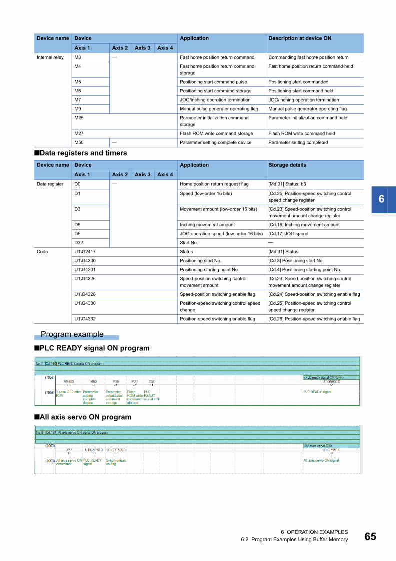
6
Data registers and timers
Program example
PLC READY signal ON program
All axis servo ON program
Internal relay M3 Fast home position return command Commanding fast home position return
M4 Fast home position return command
storage
Fast home position return command held
M5 Positioning start command pulse Positioning start commanded
M6 Positioning start command storage Positioning start command held
M7 JOG/inching operation termination JOG/inching operation termination
M9 Manual pulse generator operating flag Manual pulse generator operating flag
M25 Parameter initialization command
storage
Parameter initialization command held
M27 Flash ROM write command storage Flash ROM write command held
M50 Parameter setting complete device Parameter setting completed
Device name Device Application Storage details
Axis 1 Axis 2 Axis 3 Axis 4
Data register D0 Home position return request flag [Md.31] Status: b3
D1 Speed (low-order 16 bits) [Cd.25] Position-speed switching control
speed change register
D3 Movement amount (low-order 16 bits) [Cd.23] Speed-position switching control
movement amount change register
D5 Inching movement amount [Cd.16] Inching movement amount
D6 JOG operation speed (low-order 16 bits) [Cd.17] JOG speed
D32 Start No.
Code U1\G2417 Status [Md.31] Status
U1\G4300 Positioning start No. [Cd.3] Positioning start No.
U1\G4301 Positioning starting point No. [Cd.4] Positioning starting point No.
U1\G4326 Speed-position switching control
movement amount
[Cd.23] Speed-position switching control
movement amount change register
U1\G4328 Speed-position switching enable flag [Cd.24] Speed-position switching enable flag
U1\G4330 Position-speed switching control speed
change
[Cd.25] Position-speed switching control
speed change register
U1\G4332 Position-speed switching enable flag [Cd.26] Position-speed switching enable flag
Device name Device Application Description at device ON
Axis 1 Axis 2 Axis 3 Axis 4
6 OPERATION EXAMPLES6.2 Program Examples Using Buffer Memory 65

66
Positioning start No. setting program
6 OPERATION EXAMPLES6.2 Program Examples Using Buffer Memory
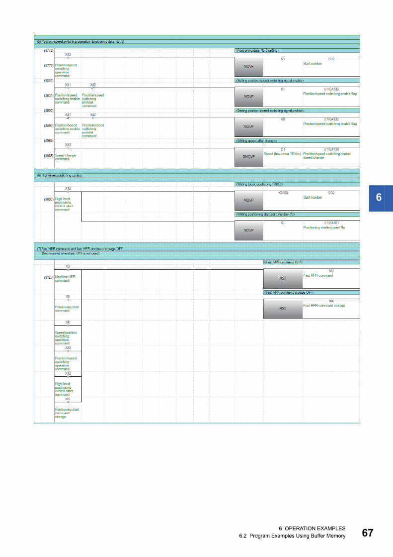
6
6 OPERATION EXAMPLES6.2 Program Examples Using Buffer Memory 67
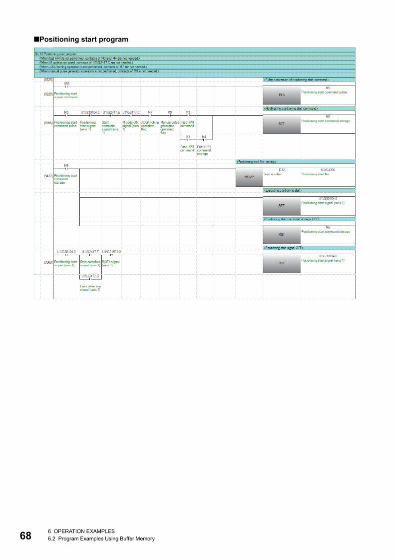
68
Positioning start program
6 OPERATION EXAMPLES6.2 Program Examples Using Buffer Memory
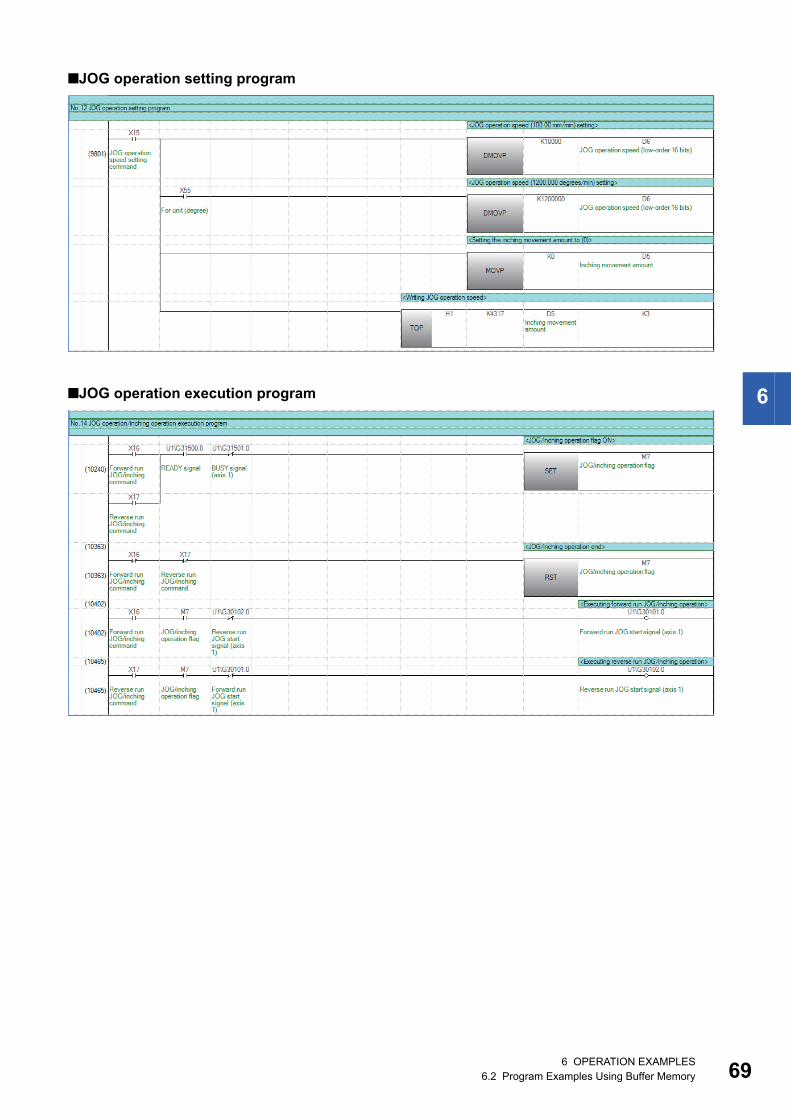
6
JOG operation setting program
JOG operation execution program
6 OPERATION EXAMPLES6.2 Program Examples Using Buffer Memory 69
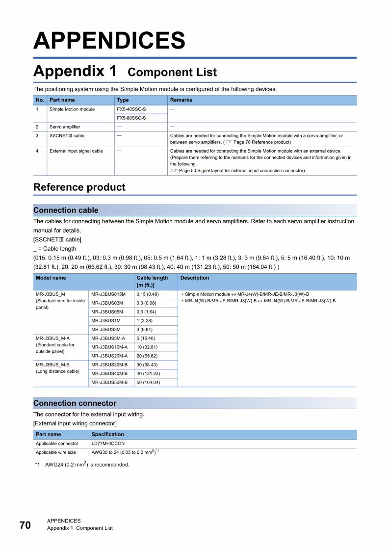
70
APPENDICESAppendix 1 Component ListThe positioning system using the Simple Motion module is configured of the following devices.
Reference product
Connection cableThe cables for connecting between the Simple Motion module and servo amplifiers. Refer to each servo amplifier instruction
manual for details.
[SSCNET cable]
_ = Cable length
(015: 0.15 m (0.49 ft.), 03: 0.3 m (0.98 ft.), 05: 0.5 m (1.64 ft.), 1: 1 m (3.28 ft.), 3: 3 m (9.84 ft.), 5: 5 m (16.40 ft.), 10: 10 m
(32.81 ft.), 20: 20 m (65.62 ft.), 30: 30 m (98.43 ft.), 40: 40 m (131.23 ft.), 50: 50 m (164.04 ft.) )
Connection connectorThe connector for the external input wiring.
[External input wiring connector]
*1 AWG24 (0.2 mm2) is recommended.
No. Part name Type Remarks
1 Simple Motion module FX5-40SSC-S
FX5-80SSC-S
2 Servo amplifier
3 SSCNET cable Cables are needed for connecting the Simple Motion module with a servo amplifier, or
between servo amplifiers. (Page 70 Reference product)
4 External input signal cable Cables are needed for connecting the Simple Motion module with an external device.
(Prepare them referring to the manuals for the connected devices and information given in
the following.
Page 50 Signal layout for external input connection connector)
Model name Cable length [m (ft.)]
Description
MR-J3BUS_M
(Standard cord for inside
panel)
MR-J3BUS015M 0.15 (0.49) • Simple Motion module MR-J4(W)-B/MR-JE-B/MR-J3(W)-B
• MR-J4(W)-B/MR-JE-B/MR-J3(W)-B MR-J4(W)-B/MR-JE-B/MR-J3(W)-BMR-J3BUS03M 0.3 (0.98)
MR-J3BUS05M 0.5 (1.64)
MR-J3BUS1M 1 (3.28)
MR-J3BUS3M 3 (9.84)
MR-J3BUS_M-A
(Standard cable for
outside panel)
MR-J3BUS5M-A 5 (16.40)
MR-J3BUS10M-A 10 (32.81)
MR-J3BUS20M-A 20 (65.62)
MR-J3BUS_M-B
(Long distance cable)
MR-J3BUS30M-B 30 (98.43)
MR-J3BUS40M-B 40 (131.23)
MR-J3BUS50M-B 50 (164.04)
Part name Specification
Applicable connector LD77MHIOCON
Applicable wire size AWG30 to 24 (0.05 to 0.2 mm2)*1
APPENDICESAppendix 1 Component List
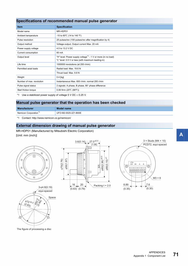
A
Specifications of recommended manual pulse generator
*1 Use a stabilized power supply of voltage 5 V DC 0.25 V.
Manual pulse generator that the operation has been checked
*1 Contact: http://www.nemicon.co.jp/nemicon/
External dimension drawing of manual pulse generatorMR-HDP01 (Manufactured by Mitsubishi Electric Corporation)
[Unit: mm (inch)]
Item Specification
Model name MR-HDP01
Ambient temperature -10 to 60 (14 to 140 )
Pulse resolution 25 pulses/rev (100 pulses/rev after magnification by 4)
Output method Voltage-output, Output current Max. 20 mA
Power supply voltage 4.5 to 13.2 V DC
Current consumption 60 mA
Output level "H" level: Power supply voltage*1 - 1 V or more (in no load)
"L" level: 0.5 V or less (with maximum leading-in)
Life time 1000000 revolutions (at 200 r/min)
Permitted axial loads Radial load: Max. 19.6 N
Thrust load: Max. 9.8 N
Weight 0.4 [kg]
Number of max. revolution Instantaneous Max. 600 r/min. normal 200 r/min
Pulse signal status 2 signals: A phase, B phase, 90 phase difference
Start friction torque 0.06 N•m (20 (68))
Manufacturer Model name
Nemicon Corporation*1 UFO-M2-0025-2Z1-B00E
3.6
50(
1.97
)
70(
2.76
)
16 20 8.89 7.6
3 × Studs (M4 × 10)PCD72, equi-spaced
M3 × 6
Packing t = 2.0
The figure of processing a disc
60(
2.36
)±0.5
80(
3.15
)±1
±0.527.0
72(2.83)
±0.2
62
(2.4
4)
+2 -0
3-4.8(0.19)equi-spaced
Space
(1.06)(0.14)
(0.63) (0.79) (0.35) (0.30)
APPENDICESAppendix 1 Component List 71
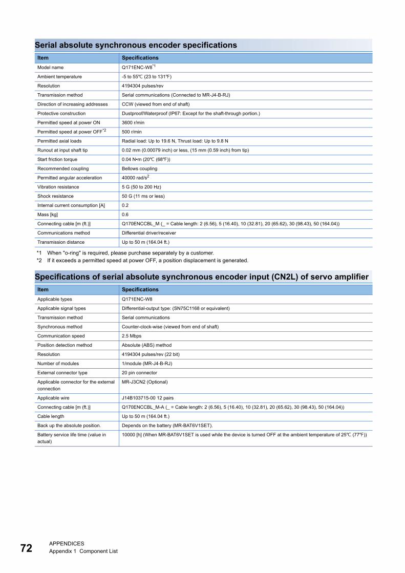
72
Serial absolute synchronous encoder specifications
*1 When "o-ring" is required, please purchase separately by a customer.*2 If it exceeds a permitted speed at power OFF, a position displacement is generated.
Specifications of serial absolute synchronous encoder input (CN2L) of servo amplifier
Item Specifications
Model name Q171ENC-W8*1
Ambient temperature -5 to 55 (23 to 131)
Resolution 4194304 pulses/rev
Transmission method Serial communications (Connected to MR-J4-B-RJ)
Direction of increasing addresses CCW (viewed from end of shaft)
Protective construction Dustproof/Waterproof (IP67: Except for the shaft-through portion.)
Permitted speed at power ON 3600 r/min
Permitted speed at power OFF*2 500 r/min
Permitted axial loads Radial load: Up to 19.6 N, Thrust load: Up to 9.8 N
Runout at input shaft tip 0.02 mm (0.00079 inch) or less, (15 mm (0.59 inch) from tip)
Start friction torque 0.04 N•m (20 (68))
Recommended coupling Bellows coupling
Permitted angular acceleration 40000 rad/s2
Vibration resistance 5 G (50 to 200 Hz)
Shock resistance 50 G (11 ms or less)
Internal current consumption [A] 0.2
Mass [kg] 0.6
Connecting cable [m (ft.)] Q170ENCCBL_M (_ = Cable length: 2 (6.56), 5 (16.40), 10 (32.81), 20 (65.62), 30 (98.43), 50 (164.04))
Communications method Differential driver/receiver
Transmission distance Up to 50 m (164.04 ft.)
Item Specifications
Applicable types Q171ENC-W8
Applicable signal types Differential-output type: (SN75C1168 or equivalent)
Transmission method Serial communications
Synchronous method Counter-clock-wise (viewed from end of shaft)
Communication speed 2.5 Mbps
Position detection method Absolute (ABS) method
Resolution 4194304 pulses/rev (22 bit)
Number of modules 1/module (MR-J4-B-RJ)
External connector type 20 pin connector
Applicable connector for the external
connection
MR-J3CN2 (Optional)
Applicable wire J14B103715-00 12 pairs
Connecting cable [m (ft.)] Q170ENCCBL_M-A (_ = Cable length: 2 (6.56), 5 (16.40), 10 (32.81), 20 (65.62), 30 (98.43), 50 (164.04))
Cable length Up to 50 m (164.04 ft.)
Back up the absolute position. Depends on the battery (MR-BAT6V1SET).
Battery service life time (value in
actual)
10000 [h] (When MR-BAT6V1SET is used while the device is turned OFF at the ambient temperature of 25 (77))
APPENDICESAppendix 1 Component List
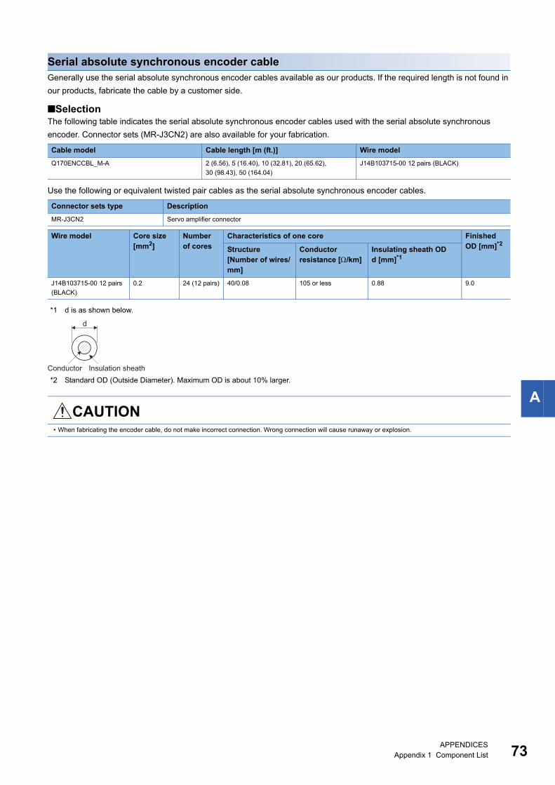
A
Serial absolute synchronous encoder cableGenerally use the serial absolute synchronous encoder cables available as our products. If the required length is not found in
our products, fabricate the cable by a customer side.
SelectionThe following table indicates the serial absolute synchronous encoder cables used with the serial absolute synchronous
encoder. Connector sets (MR-J3CN2) are also available for your fabrication.
Use the following or equivalent twisted pair cables as the serial absolute synchronous encoder cables.
*1 d is as shown below.
*2 Standard OD (Outside Diameter). Maximum OD is about 10% larger.
Cable model Cable length [m (ft.)] Wire model
Q170ENCCBL_M-A 2 (6.56), 5 (16.40), 10 (32.81), 20 (65.62),
30 (98.43), 50 (164.04)
J14B103715-00 12 pairs (BLACK)
Connector sets type Description
MR-J3CN2 Servo amplifier connector
Wire model Core size [mm2]
Number of cores
Characteristics of one core Finished OD [mm]*2Structure
[Number of wires/mm]
Conductor resistance [/km]
Insulating sheath ODd [mm]*1
J14B103715-00 12 pairs
(BLACK)
0.2 24 (12 pairs) 40/0.08 105 or less 0.88 9.0
CAUTION• When fabricating the encoder cable, do not make incorrect connection. Wrong connection will cause runaway or explosion.
Conductor Insulation sheath
d
APPENDICESAppendix 1 Component List 73
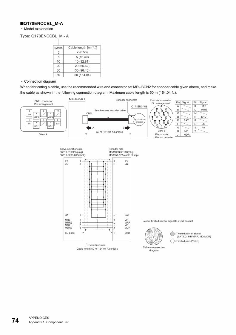
74
Q170ENCCBL_M-A • Model explanation
• Connection diagram
When fabricating a cable, use the recommended wire and connector set MR-J3CN2 for encoder cable given above, and make
the cable as shown in the following connection diagram. Maximum cable length is 50 m (164.04 ft.).
Type: Q170ENCCBL_M - A
2Cable length [m (ft.)]
5
Symbol
102030
2 (6.56)5 (16.40)
10 (32.81)20 (65.62)30 (98.43)
50 50 (164.04)
:
:
CN2L connectorPin arrangement
Encoder connectorPin arrangement
50 m (164.04 ft.) or less
MR-J4-B-RJ
Synchronousencoder
Encoder connector
Synchronous encoder cableQ171ENC-W8
SignalPin SignalPin
View AView B
BA
Encoder sideMS3106B22-14S(plug)MS3057-12A(cable clump)
Cable length 50 m (164.04 ft.) or less
LG 2
BAT
MR2 3MRR2 4MD2 7MDR2 8
P5
SD plate
R
E
KLHJ
S
N
Servo amplifier side36210-0100PL(plug)36310-3200-008(shell)
: Twisted pair cable
Twisted pair for signal(BAT/LG, MR/MRR, MD/MDR)
Twisted pair (P5/LG)
Cable cross-sectiondiagram
Layout twisted pair for signal to avoid contact.
BAT
MRMRRMDMDR
LGP5
SHD
CN2L
: Pin provided: Pin not provided
1
9
MRMRR
KLMN SHDPR LGS P5TMD
MDR
BAT
ABCDEFGHJ
2
LG 4
MRR2
68
MDR2
10
1
P5 3
MR2
57
MD2
9
BAT
A
G
T P
F
J
E
L M
CS RH D
NK BU
V
APPENDICESAppendix 1 Component List
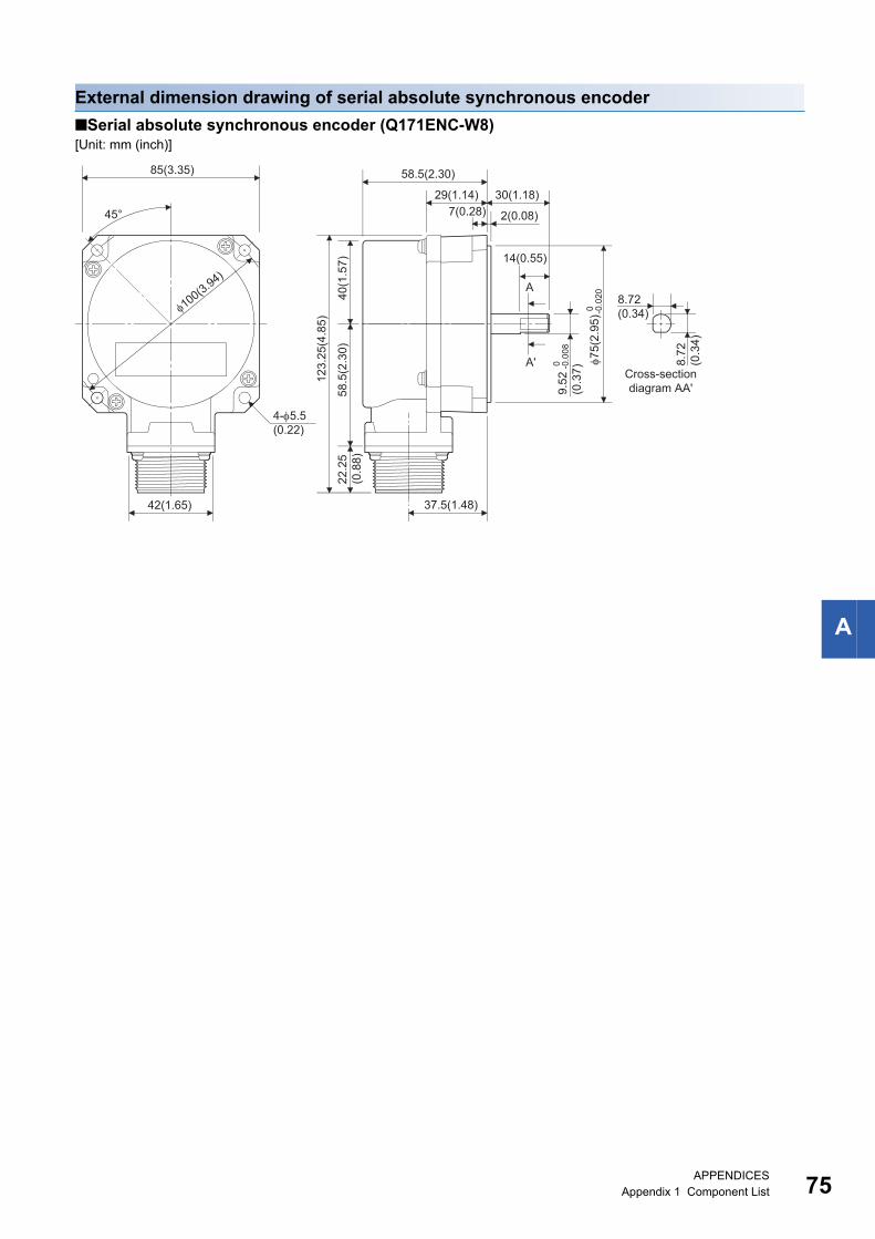
A
External dimension drawing of serial absolute synchronous encoder
Serial absolute synchronous encoder (Q171ENC-W8)[Unit: mm (inch)]
7(0.28)
Cross-sectiondiagram AA'
29(1.14)
58.5(2.30)
40(1
.57)
58.5
(2.3
0)22
.25
(0.8
8)
123.
25(4
.85)
37.5(1.48)
8.72(0.34)
42(1.65)
85(3.35)
8.72
(0.3
4)
4-5.5(0.22)
45° 2(0.08)
30(1.18)
A
A'
14(0.55)
100(3.94)
75(
2.95
)0 -0.0
20
9.52
(0.3
7)
0 -0.0
08
APPENDICESAppendix 1 Component List 75
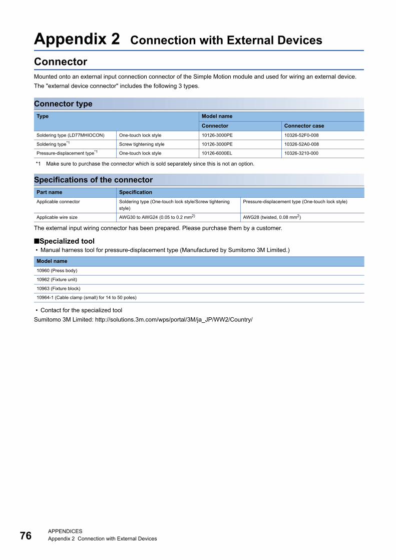
76
Appendix 2 Connection with External Devices
ConnectorMounted onto an external input connection connector of the Simple Motion module and used for wiring an external device.
The "external device connector" includes the following 3 types.
Connector type
*1 Make sure to purchase the connector which is sold separately since this is not an option.
Specifications of the connector
The external input wiring connector has been prepared. Please purchase them by a customer.
Specialized tool • Manual harness tool for pressure-displacement type (Manufactured by Sumitomo 3M Limited.)
• Contact for the specialized tool
Sumitomo 3M Limited: http://solutions.3m.com/wps/portal/3M/ja_JP/WW2/Country/
Type Model name
Connector Connector case
Soldering type (LD77MHIOCON) One-touch lock style 10126-3000PE 10326-52F0-008
Soldering type*1 Screw tightening style 10126-3000PE 10326-52A0-008
Pressure-displacement type*1 One-touch lock style 10126-6000EL 10326-3210-000
Part name Specification
Applicable connector Soldering type (One-touch lock style/Screw tightening
style)
Pressure-displacement type (One-touch lock style)
Applicable wire size AWG30 to AWG24 (0.05 to 0.2 mm2) AWG28 (twisted, 0.08 mm2)
Model name
10960 (Press body)
10962 (Fixture unit)
10963 (Fixture block)
10964-1 (Cable clamp (small) for 14 to 50 poles)
APPENDICESAppendix 2 Connection with External Devices
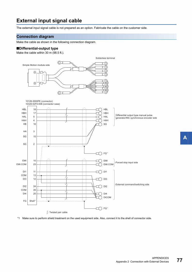
A
External input signal cableThe external input signal cable is not prepared as an option. Fabricate the cable on the customer side.
Connection diagramMake the cable as shown in the following connection diagram.
Differential-output typeMake the cable within 30 m (98.5 ft.).
*1 Make sure to perform shield treatment on the used equipment side. Also, connect it to the shell of connector side.
HBLHBL 18HBH 17HAL 5HAH 4
HB 16
HA 3
EMIEMI 10EMI.COMEMI.COM 23
DI1
DI3
HALHAH
FG*1
Forced stop input side
External command/switching side
HBH
DI1 11COM 13
DI3 12
DI2 24COM 26
DI4 25
DI2
DI4DICOM
FG Shell*1
: Twisted pair cable
10126-3000PE (connector)10326-52F0-008 (connector case)
Solderless terminal
Simple Motion module side
FG*1
Differential output type manual pulse generator/INC synchronous encoder side
SG 15
SG 2
SG
APPENDICESAppendix 2 Connection with External Devices 77
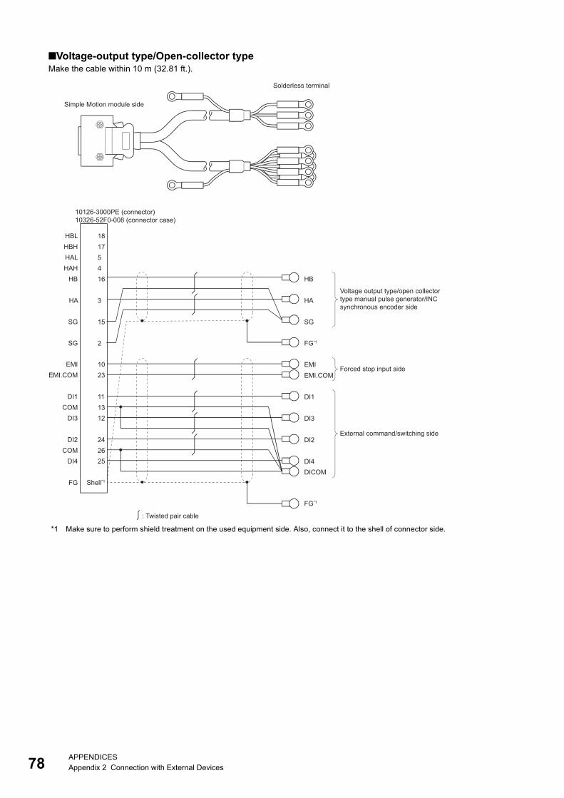
78
Voltage-output type/Open-collector typeMake the cable within 10 m (32.81 ft.).
*1 Make sure to perform shield treatment on the used equipment side. Also, connect it to the shell of connector side.
HBL 18HBH 17HAL 5HAH 4
HB 16
SG 2
SG 15
HA 3
EMIEMI 10EMI.COMEMI.COM 23
DI1
DI3
Forced stop input side
External command/switching side
DI1 11COM 13
DI3 12
DI2 24COM 26
DI4 25
DI2
DI4DICOM
FG
: Twisted pair cable
10126-3000PE (connector)10326-52F0-008 (connector case)
Solderless terminal
HB
SG
HA
FG*1
Shell*1
FG*1
Voltage output type/open collector type manual pulse generator/INC synchronous encoder side
Simple Motion module side
APPENDICESAppendix 2 Connection with External Devices
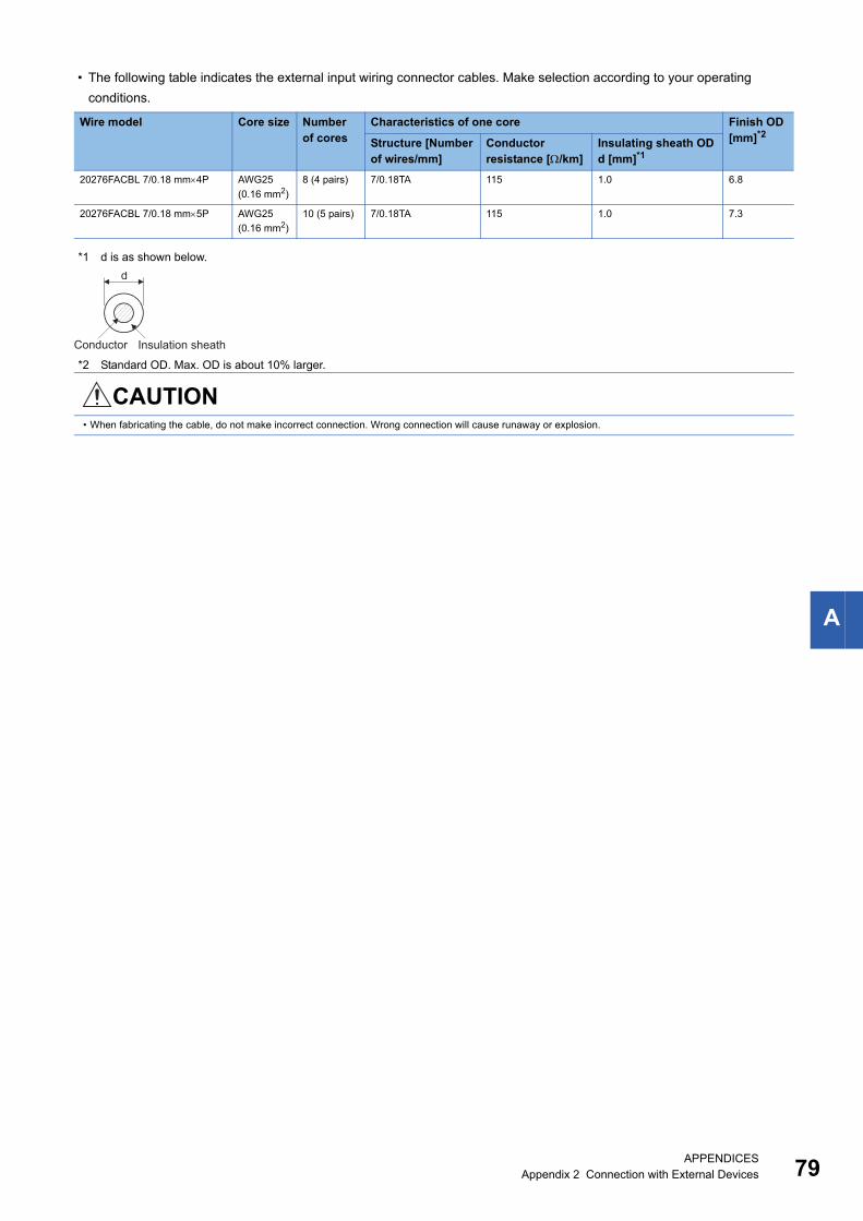
A
• The following table indicates the external input wiring connector cables. Make selection according to your operating
conditions.
*1 d is as shown below.
*2 Standard OD. Max. OD is about 10% larger.
Wire model Core size Number of cores
Characteristics of one core Finish OD [mm]*2Structure [Number
of wires/mm]Conductor resistance [/km]
Insulating sheath ODd [mm]*1
20276FACBL 7/0.18 mm4P AWG25
(0.16 mm2)
8 (4 pairs) 7/0.18TA 115 1.0 6.8
20276FACBL 7/0.18 mm5P AWG25
(0.16 mm2)
10 (5 pairs) 7/0.18TA 115 1.0 7.3
CAUTION• When fabricating the cable, do not make incorrect connection. Wrong connection will cause runaway or explosion.
Conductor Insulation sheath
d
APPENDICESAppendix 2 Connection with External Devices 79
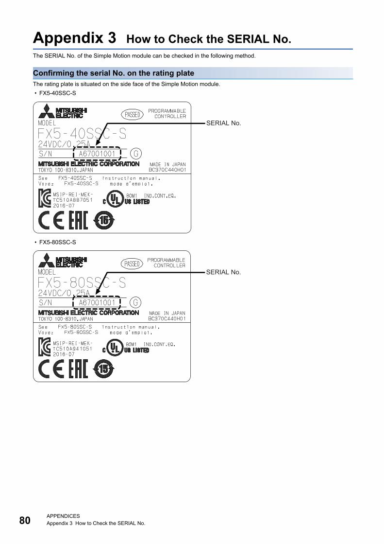
80APPENDICESAppendix 3 How to Check the SERIAL No.
Appendix 3 How to Check the SERIAL No.The SERIAL No. of the Simple Motion module can be checked in the following method.
Confirming the serial No. on the rating plateThe rating plate is situated on the side face of the Simple Motion module.
• FX5-40SSC-S
• FX5-80SSC-S
SERIAL No.
SERIAL No.
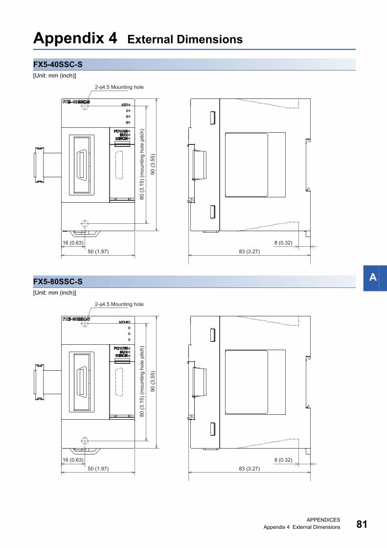
APPENDICESAppendix 4 External Dimensions 81
A
Appendix 4 External Dimensions
FX5-40SSC-S[Unit: mm (inch)]
FX5-80SSC-S[Unit: mm (inch)]
16 (0.63)
50 (1.97)
80 (3
.15)
(mou
ntin
g ho
le p
itch)
90 (3
.55)
8 (0.32)
83 (3.27)
2-φ4.5 Mounting hole
16 (0.63)
50 (1.97)
80 (3
.15)
(mou
ntin
g ho
le p
itch)
90 (3
.55)
8 (0.32)
83 (3.27)
2-φ4.5 Mounting hole
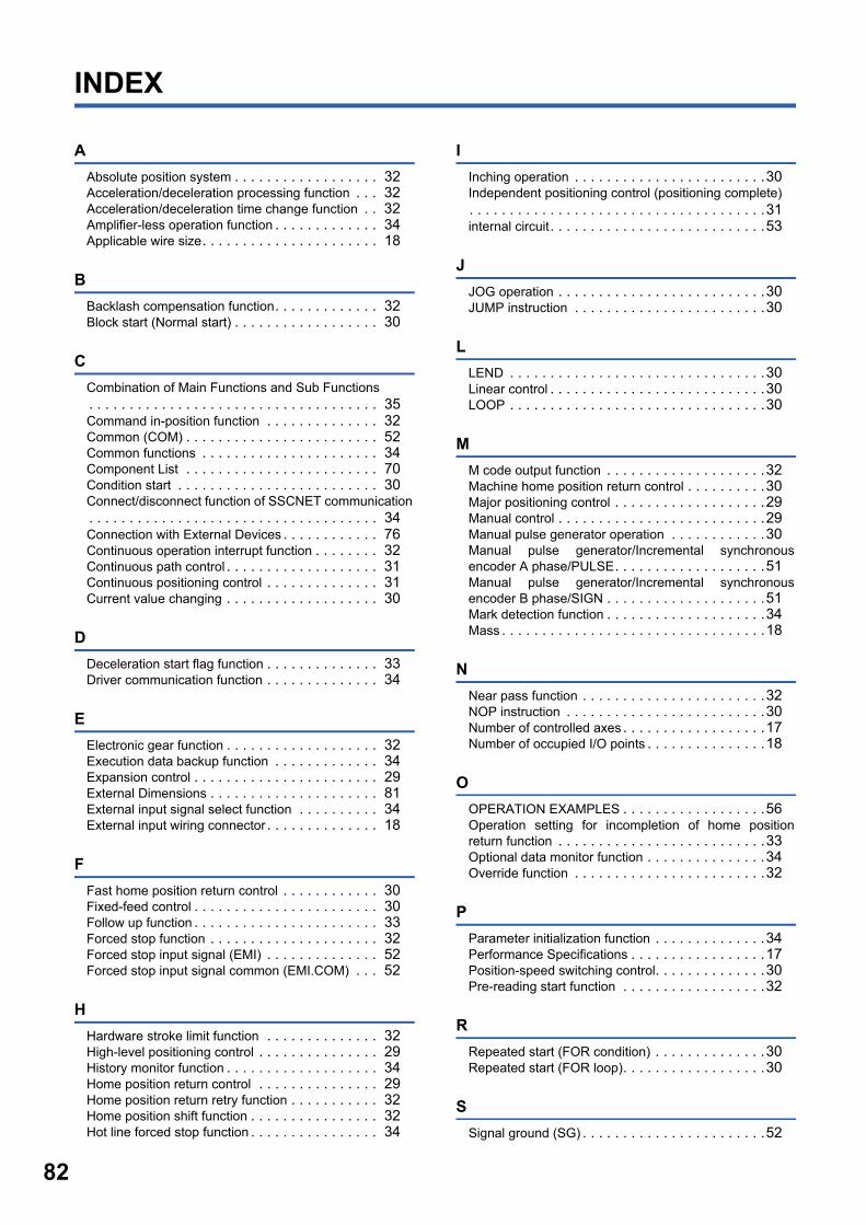
82
INDEX
A
Absolute position system . . . . . . . . . . . . . . . . . . 32Acceleration/deceleration processing function . . . 32Acceleration/deceleration time change function . . 32Amplifier-less operation function . . . . . . . . . . . . . 34Applicable wire size. . . . . . . . . . . . . . . . . . . . . . 18
B
Backlash compensation function. . . . . . . . . . . . . 32Block start (Normal start) . . . . . . . . . . . . . . . . . . 30
C
Combination of Main Functions and Sub Functions. . . . . . . . . . . . . . . . . . . . . . . . . . . . . . . . . . . . 35Command in-position function . . . . . . . . . . . . . . 32Common (COM) . . . . . . . . . . . . . . . . . . . . . . . . 52Common functions . . . . . . . . . . . . . . . . . . . . . . 34Component List . . . . . . . . . . . . . . . . . . . . . . . . 70Condition start . . . . . . . . . . . . . . . . . . . . . . . . . 30Connect/disconnect function of SSCNET communication. . . . . . . . . . . . . . . . . . . . . . . . . . . . . . . . . . . . 34Connection with External Devices . . . . . . . . . . . . 76Continuous operation interrupt function . . . . . . . . 32Continuous path control . . . . . . . . . . . . . . . . . . . 31Continuous positioning control . . . . . . . . . . . . . . 31Current value changing . . . . . . . . . . . . . . . . . . . 30
D
Deceleration start flag function . . . . . . . . . . . . . . 33Driver communication function . . . . . . . . . . . . . . 34
E
Electronic gear function . . . . . . . . . . . . . . . . . . . 32Execution data backup function . . . . . . . . . . . . . 34Expansion control . . . . . . . . . . . . . . . . . . . . . . . 29External Dimensions . . . . . . . . . . . . . . . . . . . . . 81External input signal select function . . . . . . . . . . 34External input wiring connector . . . . . . . . . . . . . . 18
F
Fast home position return control . . . . . . . . . . . . 30Fixed-feed control . . . . . . . . . . . . . . . . . . . . . . . 30Follow up function . . . . . . . . . . . . . . . . . . . . . . . 33Forced stop function . . . . . . . . . . . . . . . . . . . . . 32Forced stop input signal (EMI) . . . . . . . . . . . . . . 52Forced stop input signal common (EMI.COM) . . . 52
H
Hardware stroke limit function . . . . . . . . . . . . . . 32High-level positioning control . . . . . . . . . . . . . . . 29History monitor function . . . . . . . . . . . . . . . . . . . 34Home position return control . . . . . . . . . . . . . . . 29Home position return retry function . . . . . . . . . . . 32Home position shift function . . . . . . . . . . . . . . . . 32Hot line forced stop function . . . . . . . . . . . . . . . . 34
I
Inching operation . . . . . . . . . . . . . . . . . . . . . . . .30Independent positioning control (positioning complete). . . . . . . . . . . . . . . . . . . . . . . . . . . . . . . . . . . . .31internal circuit. . . . . . . . . . . . . . . . . . . . . . . . . . .53
J
JOG operation . . . . . . . . . . . . . . . . . . . . . . . . . .30JUMP instruction . . . . . . . . . . . . . . . . . . . . . . . .30
L
LEND . . . . . . . . . . . . . . . . . . . . . . . . . . . . . . . .30Linear control . . . . . . . . . . . . . . . . . . . . . . . . . . .30LOOP . . . . . . . . . . . . . . . . . . . . . . . . . . . . . . . .30
M
M code output function . . . . . . . . . . . . . . . . . . . .32Machine home position return control . . . . . . . . . .30Major positioning control . . . . . . . . . . . . . . . . . . .29Manual control . . . . . . . . . . . . . . . . . . . . . . . . . .29Manual pulse generator operation . . . . . . . . . . . .30Manual pulse generator/Incremental synchronousencoder A phase/PULSE. . . . . . . . . . . . . . . . . . .51Manual pulse generator/Incremental synchronousencoder B phase/SIGN . . . . . . . . . . . . . . . . . . . .51Mark detection function . . . . . . . . . . . . . . . . . . . .34Mass . . . . . . . . . . . . . . . . . . . . . . . . . . . . . . . . .18
N
Near pass function . . . . . . . . . . . . . . . . . . . . . . .32NOP instruction . . . . . . . . . . . . . . . . . . . . . . . . .30Number of controlled axes . . . . . . . . . . . . . . . . . .17Number of occupied I/O points . . . . . . . . . . . . . . .18
O
OPERATION EXAMPLES . . . . . . . . . . . . . . . . . .56Operation setting for incompletion of home positionreturn function . . . . . . . . . . . . . . . . . . . . . . . . . .33Optional data monitor function . . . . . . . . . . . . . . .34Override function . . . . . . . . . . . . . . . . . . . . . . . .32
P
Parameter initialization function . . . . . . . . . . . . . .34Performance Specifications . . . . . . . . . . . . . . . . .17Position-speed switching control. . . . . . . . . . . . . .30Pre-reading start function . . . . . . . . . . . . . . . . . .32
R
Repeated start (FOR condition) . . . . . . . . . . . . . .30Repeated start (FOR loop). . . . . . . . . . . . . . . . . .30
S
Signal ground (SG) . . . . . . . . . . . . . . . . . . . . . . .52
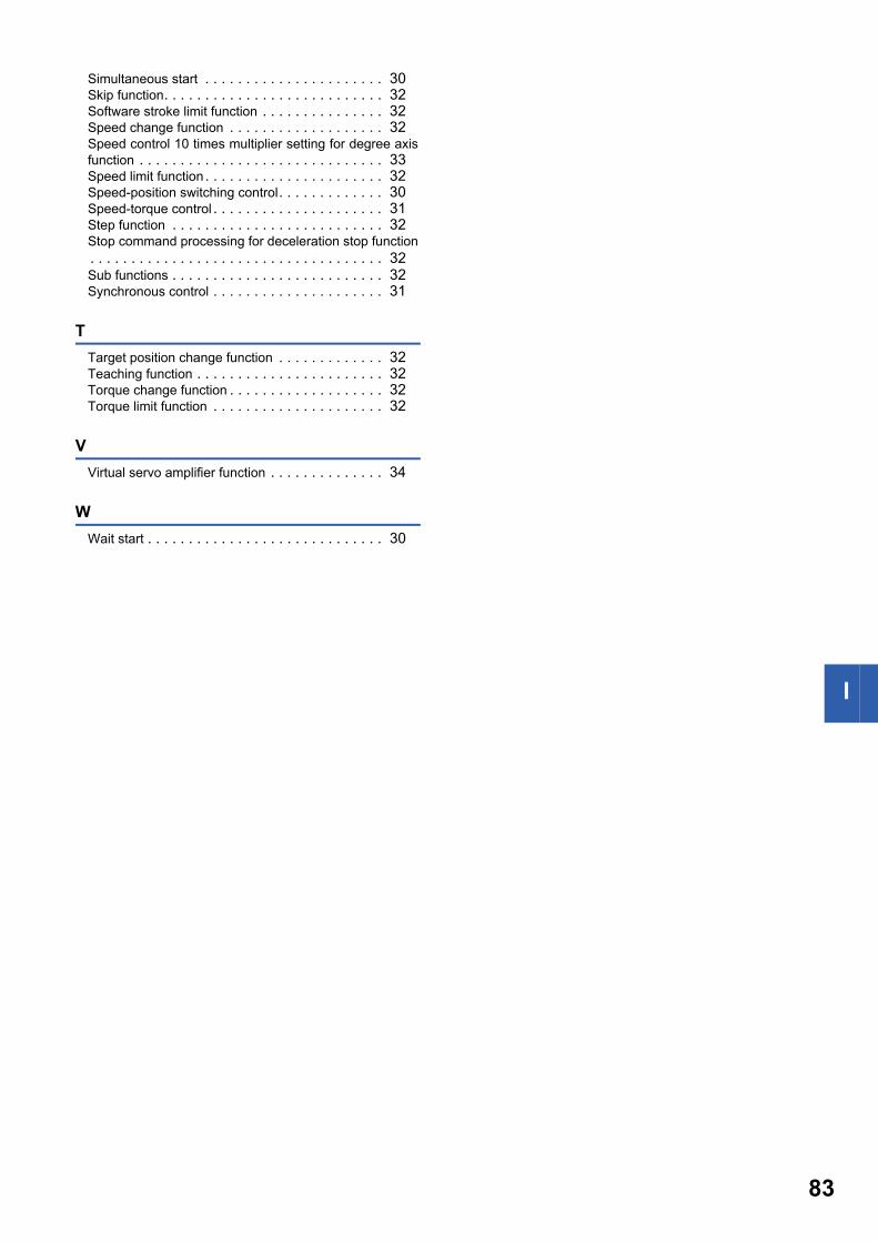
I
Simultaneous start . . . . . . . . . . . . . . . . . . . . . . 30Skip function. . . . . . . . . . . . . . . . . . . . . . . . . . . 32Software stroke limit function . . . . . . . . . . . . . . . 32Speed change function . . . . . . . . . . . . . . . . . . . 32Speed control 10 times multiplier setting for degree axisfunction . . . . . . . . . . . . . . . . . . . . . . . . . . . . . . 33Speed limit function. . . . . . . . . . . . . . . . . . . . . . 32Speed-position switching control. . . . . . . . . . . . . 30Speed-torque control . . . . . . . . . . . . . . . . . . . . . 31Step function . . . . . . . . . . . . . . . . . . . . . . . . . . 32Stop command processing for deceleration stop function. . . . . . . . . . . . . . . . . . . . . . . . . . . . . . . . . . . . 32Sub functions . . . . . . . . . . . . . . . . . . . . . . . . . . 32Synchronous control . . . . . . . . . . . . . . . . . . . . . 31
T
Target position change function . . . . . . . . . . . . . 32Teaching function . . . . . . . . . . . . . . . . . . . . . . . 32Torque change function . . . . . . . . . . . . . . . . . . . 32Torque limit function . . . . . . . . . . . . . . . . . . . . . 32
V
Virtual servo amplifier function . . . . . . . . . . . . . . 34
W
Wait start . . . . . . . . . . . . . . . . . . . . . . . . . . . . . 30
83
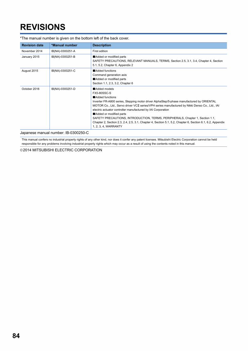
84
REVISIONS*The manual number is given on the bottom left of the back cover.
Japanese manual number: IB-0300250-C
2014 MITSUBISHI ELECTRIC CORPORATION
Revision date *Manual number Description
November 2014 IB(NA)-0300251-A First edition
January 2015 IB(NA)-0300251-B Added or modified parts
SAFETY PRECAUTIONS, RELEVANT MANUALS, TERMS, Section 2.5, 3.1, 3.4, Chapter 4, Section
5.1, 5.2, Chapter 6, Appendix 2
August 2015 IB(NA)-0300251-C Added functions
Command generation axis
Added or modified parts
Section 1.1, 2.3, 3.2, Chapter 6
October 2016 IB(NA)-0300251-D Added models
FX5-80SSC-S
Added functions
Inverter FR-A800 series, Stepping motor driver AlphaStep/5-phase manufactured by ORIENTAL
MOTOR Co., Ltd., Servo driver VC series/VPH series manufactured by Nikki Denso Co., Ltd., IAI
electric actuator controller manufactured by IAI Corporation
Added or modified parts
SAFETY PRECAUTIONS, INTRODUCTION, TERMS, PERIPHERALS, Chapter 1, Section 1.1,
Chapter 2, Section 2.3, 2.4, 2.5, 3.1, Chapter 4, Section 5.1, 5.2, Chapter 6, Section 6.1, 6.2, Appendix
1, 2, 3, 4, WARRANTY
This manual confers no industrial property rights of any other kind, nor does it confer any patent licenses. Mitsubishi Electric Corporation cannot be held
responsible for any problems involving industrial property rights which may occur as a result of using the contents noted in this manual.
85
WARRANTY
1.Please confirm the following product warranty details before using this product.
[Gratis Warranty Term]
If any faults or defects (hereinafter "Failure") found to be the responsibility of Mitsubishi occurs during use of the product within the gratis warranty term, the product shall be repaired at no cost via the sales representative or Mitsubishi Service Company. However, if repairs are required onsite at domestic or overseas location, expenses to send an engineer will be solely at the customer's discretion. Mitsubishi shall not be held responsible for any re-commissioning, maintenance, or testing on-site that involves replacement of the failed module.
Overseas, repairs shall be accepted by Mitsubishi's local overseas FA Center. Note that the repair conditions at each FA Center may differ.
The gratis warranty term of the product shall be for one year after the date of purchase or delivery to a designated place. Note that after manufacture and shipment from Mitsubishi, the maximum distribution period shall be six (6) months, and the longest gratis warranty term after manufacturing shall be eighteen (18) months. The gratis warranty term of repair parts shall not exceed the gratis warranty term before repairs.
[Gratis Warranty Range] The range shall be limited to normal use within the usage state, usage methods and usage environment, etc., which follow the conditions and precautions, etc., given in the instruction manual, user's manual and caution labels on the product.
(1)
Even within the gratis warranty term, repairs shall be charged for in the following cases.
(2)
Failure occurring from inappropriate storage or handling, carelessness or negligence by the user. Failure caused by the user's hardware or software design.
1.
Failure caused by unapproved modifications, etc., to the product by the user.
2.
Mitsubishi shall accept onerous product repairs for seven (7) years after production of the product is discontinued.Discontinuation of production shall be notified with Mitsubishi Technical Bulletins, etc.
(1)
Product supply (including repair parts) is not available after production is discontinued.
(2)
In using the Mitsubishi MELSEC programmable controller, the usage conditions shall be that the application will not lead to a major accident even if any problem or fault should occur in the programmable controller device, and that backup and fail-safe functions are systematically provided outside of the device for any problem or fault.
(1)
The Mitsubishi programmable controller has been designed and manufactured for applications in general industries, etc. Thus, applications in which the public could be affected such as in nuclear power plants and other power plants operated by respective power companies, and applications in which a special quality assurance system is required, such as for railway companies or public service purposes shall be excluded from the programmable controller applications. In addition, applications in which human life or property that could be greatly affected, such as in aircraft, medical applications, incineration and fuel devices, manned transportation, equipment for recreation and amusement, and safety devices, shall also be excluded from the programmable controller range of applications. However, in certain cases, some applications may be possible, providing the user consults their local Mitsubishi representative outlining the special requirements of the project, and providing that all parties concerned agree to the special circumstances, solely at the user's discretion.
(2)
When the Mitsubishi product is assembled into a user's device, Failure that could have been avoided if functions or structures, judged as necessary in the legal safety measures the user's device is subject to or as necessary by industry standards, had been provided.
3.
Failure that could have been avoided if consumable parts (battery, backlight, fuse, etc.) designated in the instruction manual had been correctly serviced or replaced.
4.
Relay failure or output contact failure caused by usage beyond the specified life of contact (cycles).
5.
Failure caused by external irresistible forces such as fires or abnormal voltages, and failure caused by force majeure such as earthquakes, lightning, wind and water damage.
6.
Failure caused by reasons unpredictable by scientific technology standards at time of shipment from Mitsubishi.
7.
Any other failure found not to be the responsibility of Mitsubishi or that admitted not to be so by the user.
8.
2. Onerous repair term after discontinuation of production
Gratis Warranty Term and Gratis Warranty Range
4. Exclusion of loss in opportunity and secondary loss from warranty liability
3. Overseas service
The specifications given in the catalogs, manuals or technical documents are subject to change without prior notice.
5. Changes in product specifications
6. Product application
Regardless of the gratis warranty term, Mitsubishi shall not be liable for compensation to:(1) Damages caused by any cause found not to be
the responsibility of Mitsubishi.(2) Loss in opportunity, lost profits incurred to the
user by Failures of Mitsubishi products.(3) Special damages and secondary damages
whether foreseeable or not, compensation for accidents, and compensation for damages to products other than Mitsubishi products.
(4) Replacement by the user, maintenance of on-site equipment, start-up test run and other tasks.

86
TRADEMARKSEthernet is a registered trademark of Fuji Xerox Co., Ltd. in Japan.
Microsoft and Windows are either registered trademarks or trademarks of Microsoft Corporation in the United States and/or
other countries.
The company names, system names and product names mentioned in this manual are either registered trademarks or
trademarks of their respective companies.
In some cases, trademark symbols such as '' or '' are not specified in this manual.


Manual number: IB(NA)-0300251ENG-D(1610)MEE
Model: FX5SSC-U-S-E
Model code: 1XB018
HEAD OFFICE: TOKYO BUILDING, 2-7-3 MARUNOUCHI, CHIYODA-KU, TOKYO 100-8310, JAPANNAGOYA WORKS: 1-14, YADA-MINAMI 5-CHOME, HIGASHI-KU, NAGOYA, JAPAN
Specifications are subject to change without notice.
When exported from Japan, this manual does not require application to the Ministry of Economy, Trade and Industry for service transaction permission.