Embed Size (px)
Citation preview
MELSEC Communication Protocol Reference Manual
-RJ71C24-RJ71C24-R2-RJ71C24-R4-LJ71C24-LJ71C24-R2-LJ71E71-100-QJ71C24N-QJ71C24N-R2-QJ71C24N-R4-QJ71C24-QJ71C24-R2-QJ71E71-100-QJ71E71-B5-QJ71E71-B2


1
SAFETY PRECAUTIONS(Read these precautions before using this product.)
Before using this product, please read this manual and the relevant manuals carefully and pay full attention to safety to handle
the product correctly.
Note that these precautions apply only to this product. For the safety precautions of the programmable controller system,
please read the User's Manual for the CPU module used.
In this manual, the safety precautions are classified into two levels: " WARNING" and " CAUTION".
Under some circumstances, failure to observe the precautions given under " CAUTION" may lead to serious
consequences.
Observe the precautions of both levels because they are important for personal and system safety.
Make sure that the end users read this manual and then keep the manual in a safe place for future reference.
[Design precautions]
WARNING● When connecting an external device with a CPU module or intelligent function module to modify data
of a running programmable controller, configure an interlock circuit in the program to ensure that the
entire system will always operate safely. For other forms of control (such as program modification,
parameter change, forced output, or operating status change) of a running programmable controller,
read the relevant manuals carefully and ensure that the operation is safe before proceeding. Improper
operation may damage machines or cause accidents.
● Especially, when a remote programmable controller is controlled by an external device, immediate
action cannot be taken if a problem occurs in the programmable controller due to a communication
failure. To prevent this, configure an interlock circuit in the program, and determine corrective actions
to be taken between the external device and CPU module in case of a communication failure.
● Do not write any data to the "system area" and "write-protect area" of the buffer memory in the
module. Also, do not use any "use prohibited" signals as an output signal from the CPU module to
each module. Doing so may cause malfunction of the programmable controller system. For the
"system area", "write-protect area", and the "use prohibited" signals, refer to the user's manual for the
module used.
WARNING Indicates that incorrect handling may cause hazardous conditions, resulting in death or severe injury.
CAUTION Indicates that incorrect handling may cause hazardous conditions, resulting in minor or moderate injury or property damage.

2
[Operating precautions]
CAUTION● When changing data and operating status, and modifying program of the running programmable
controller from an external device such as a personal computer connected to an intelligent function
module, read relevant manuals carefully and ensure the safety before operation. Incorrect change or
modification may cause system malfunction, damage to the machines, or accidents.
● Do not power off the programmable controller or reset the CPU module while the setting values in the
buffer memory are being written to the flash ROM in the module. Doing so will make the data in the
flash ROM undefined. The values need to be set in the buffer memory and written to the flash ROM
again. Doing so also can cause malfunction or failure of the module.

3
CONDITIONS OF USE FOR THE PRODUCT(1) Mitsubishi programmable controller ("the PRODUCT") shall be used in conditions;
i) where any problem, fault or failure occurring in the PRODUCT, if any, shall not lead to any major or serious accident; and ii) where the backup and fail-safe function are systematically or automatically provided outside of the PRODUCT for the case of any problem, fault or failure occurring in the PRODUCT.
(2) The PRODUCT has been designed and manufactured for the purpose of being used in general industries.MITSUBISHI SHALL HAVE NO RESPONSIBILITY OR LIABILITY (INCLUDING, BUT NOT LIMITED TO ANY AND ALL RESPONSIBILITY OR LIABILITY BASED ON CONTRACT, WARRANTY, TORT, PRODUCT LIABILITY) FOR ANY INJURY OR DEATH TO PERSONS OR LOSS OR DAMAGE TO PROPERTY CAUSED BY the PRODUCT THAT ARE OPERATED OR USED IN APPLICATION NOT INTENDED OR EXCLUDED BY INSTRUCTIONS, PRECAUTIONS, OR WARNING CONTAINED IN MITSUBISHI'S USER, INSTRUCTION AND/OR SAFETY MANUALS, TECHNICAL BULLETINS AND GUIDELINES FOR the PRODUCT. ("Prohibited Application")Prohibited Applications include, but not limited to, the use of the PRODUCT in;• Nuclear Power Plants and any other power plants operated by Power companies, and/or any other cases in which the
public could be affected if any problem or fault occurs in the PRODUCT.• Railway companies or Public service purposes, and/or any other cases in which establishment of a special quality
assurance system is required by the Purchaser or End User.• Aircraft or Aerospace, Medical applications, Train equipment, transport equipment such as Elevator and Escalator,
Incineration and Fuel devices, Vehicles, Manned transportation, Equipment for Recreation and Amusement, and Safety devices, handling of Nuclear or Hazardous Materials or Chemicals, Mining and Drilling, and/or other applications where there is a significant risk of injury to the public or property.
Notwithstanding the above, restrictions Mitsubishi may in its sole discretion, authorize use of the PRODUCT in one or more of the Prohibited Applications, provided that the usage of the PRODUCT is limited only for the specific applications agreed to by Mitsubishi and provided further that no special quality assurance or fail-safe, redundant or other safety features which exceed the general specifications of the PRODUCTs are required. For details, please contact the Mitsubishi representative in your region.

4
INTRODUCTIONThank you for purchasing the Mitsubishi Electric programmable controllers.
This manual describes the supported devices, access range, communication procedure, and message format required for
using MELSEC communication protocols listed below.
Before using this product, thoroughly read this manual and the related manuals to develop full familiarity with the functions
and performance of the programmable controller to ensure correct use.
Make sure that the end users read this manual and then keep the manual in a safe place for future reference.
Relevant productsRJ71C24, RJ71C24-R2, RJ71C24-R4,
LJ71C24, LJ71C24-R2, LJ71E71-100,
QJ71C24N, QJ71C24N-R2, QJ71C24N-R4, QJ71C24, QJ71C24-R2, QJ71E71-100, QJ71E71-B5, QJ71E71-B2

5
MEMO

6
CONTENTSSAFETY PRECAUTIONS . . . . . . . . . . . . . . . . . . . . . . . . . . . . . . . . . . . . . . . . . . . . . . . . . . . . . . . . . . . . . . . . . . . .1
CONDITIONS OF USE FOR THE PRODUCT . . . . . . . . . . . . . . . . . . . . . . . . . . . . . . . . . . . . . . . . . . . . . . . . . . . .3
INTRODUCTION. . . . . . . . . . . . . . . . . . . . . . . . . . . . . . . . . . . . . . . . . . . . . . . . . . . . . . . . . . . . . . . . . . . . . . . . . . .4
RELEVANT MANUALS . . . . . . . . . . . . . . . . . . . . . . . . . . . . . . . . . . . . . . . . . . . . . . . . . . . . . . . . . . . . . . . . . . . . .14
TERMS . . . . . . . . . . . . . . . . . . . . . . . . . . . . . . . . . . . . . . . . . . . . . . . . . . . . . . . . . . . . . . . . . . . . . . . . . . . . . . . . .15
DISCONTINUED MODELS. . . . . . . . . . . . . . . . . . . . . . . . . . . . . . . . . . . . . . . . . . . . . . . . . . . . . . . . . . . . . . . . . .16
PART 1 MELSEC COMMUNICATION PROTOCOL
CHAPTER 1 ABILITY OF MC PROTOCOL 18
1.1 Purposes . . . . . . . . . . . . . . . . . . . . . . . . . . . . . . . . . . . . . . . . . . . . . . . . . . . . . . . . . . . . . . . . . . . . . . . . . . . . . . 18
1.2 Features . . . . . . . . . . . . . . . . . . . . . . . . . . . . . . . . . . . . . . . . . . . . . . . . . . . . . . . . . . . . . . . . . . . . . . . . . . . . . . . 19
CHAPTER 2 SUPPORTED DEVICES AND ACCESSIBLE RANGES 20
2.1 Supported Devices . . . . . . . . . . . . . . . . . . . . . . . . . . . . . . . . . . . . . . . . . . . . . . . . . . . . . . . . . . . . . . . . . . . . . . 20
2.2 Accessible Range and Accessible Modules . . . . . . . . . . . . . . . . . . . . . . . . . . . . . . . . . . . . . . . . . . . . . . . . . . 20
CHAPTER 3 COMMUNICATION PROCEDURE 22
3.1 Features of Communication Process . . . . . . . . . . . . . . . . . . . . . . . . . . . . . . . . . . . . . . . . . . . . . . . . . . . . . . . 22
3.2 Considerations . . . . . . . . . . . . . . . . . . . . . . . . . . . . . . . . . . . . . . . . . . . . . . . . . . . . . . . . . . . . . . . . . . . . . . . . . 23
Considerations when connecting C24. . . . . . . . . . . . . . . . . . . . . . . . . . . . . . . . . . . . . . . . . . . . . . . . . . . . . . . . . 25
Considerations when connecting E71 . . . . . . . . . . . . . . . . . . . . . . . . . . . . . . . . . . . . . . . . . . . . . . . . . . . . . . . . . 26
PART 2 MESSAGE FORMATS
CHAPTER 4 MESSAGES OF SERIAL COMMUNICATION MODULE 28
4.1 Types and Purposes of Messages . . . . . . . . . . . . . . . . . . . . . . . . . . . . . . . . . . . . . . . . . . . . . . . . . . . . . . . . . . 28
Formats and codes . . . . . . . . . . . . . . . . . . . . . . . . . . . . . . . . . . . . . . . . . . . . . . . . . . . . . . . . . . . . . . . . . . . . . . . 28
Frame . . . . . . . . . . . . . . . . . . . . . . . . . . . . . . . . . . . . . . . . . . . . . . . . . . . . . . . . . . . . . . . . . . . . . . . . . . . . . . . . . 28
4.2 Message Formats of Each Protocol. . . . . . . . . . . . . . . . . . . . . . . . . . . . . . . . . . . . . . . . . . . . . . . . . . . . . . . . . 29
Format 1 . . . . . . . . . . . . . . . . . . . . . . . . . . . . . . . . . . . . . . . . . . . . . . . . . . . . . . . . . . . . . . . . . . . . . . . . . . . . . . . 29
Format 2 . . . . . . . . . . . . . . . . . . . . . . . . . . . . . . . . . . . . . . . . . . . . . . . . . . . . . . . . . . . . . . . . . . . . . . . . . . . . . . . 30
Format 3 . . . . . . . . . . . . . . . . . . . . . . . . . . . . . . . . . . . . . . . . . . . . . . . . . . . . . . . . . . . . . . . . . . . . . . . . . . . . . . . 31
Format 4 . . . . . . . . . . . . . . . . . . . . . . . . . . . . . . . . . . . . . . . . . . . . . . . . . . . . . . . . . . . . . . . . . . . . . . . . . . . . . . . 32
Format 5 . . . . . . . . . . . . . . . . . . . . . . . . . . . . . . . . . . . . . . . . . . . . . . . . . . . . . . . . . . . . . . . . . . . . . . . . . . . . . . . 33
4.3 Details of Setting Data . . . . . . . . . . . . . . . . . . . . . . . . . . . . . . . . . . . . . . . . . . . . . . . . . . . . . . . . . . . . . . . . . . . 34
Control code . . . . . . . . . . . . . . . . . . . . . . . . . . . . . . . . . . . . . . . . . . . . . . . . . . . . . . . . . . . . . . . . . . . . . . . . . . . . 34
Number of data bytes . . . . . . . . . . . . . . . . . . . . . . . . . . . . . . . . . . . . . . . . . . . . . . . . . . . . . . . . . . . . . . . . . . . . . 35
Block number. . . . . . . . . . . . . . . . . . . . . . . . . . . . . . . . . . . . . . . . . . . . . . . . . . . . . . . . . . . . . . . . . . . . . . . . . . . . 36
Frame ID No. . . . . . . . . . . . . . . . . . . . . . . . . . . . . . . . . . . . . . . . . . . . . . . . . . . . . . . . . . . . . . . . . . . . . . . . . . . . . 36
Sum check code . . . . . . . . . . . . . . . . . . . . . . . . . . . . . . . . . . . . . . . . . . . . . . . . . . . . . . . . . . . . . . . . . . . . . . . . . 36
End code . . . . . . . . . . . . . . . . . . . . . . . . . . . . . . . . . . . . . . . . . . . . . . . . . . . . . . . . . . . . . . . . . . . . . . . . . . . . . . . 38
Error code . . . . . . . . . . . . . . . . . . . . . . . . . . . . . . . . . . . . . . . . . . . . . . . . . . . . . . . . . . . . . . . . . . . . . . . . . . . . . . 38
CHAPTER 5 MESSAGES OF ETHERNET INTERFACE MODULE 39
5.1 Types and Purposes of Messages . . . . . . . . . . . . . . . . . . . . . . . . . . . . . . . . . . . . . . . . . . . . . . . . . . . . . . . . . . 39

7
CO
NT
EN
TS
Code . . . . . . . . . . . . . . . . . . . . . . . . . . . . . . . . . . . . . . . . . . . . . . . . . . . . . . . . . . . . . . . . . . . . . . . . . . . . . . . . . . 39
Frame . . . . . . . . . . . . . . . . . . . . . . . . . . . . . . . . . . . . . . . . . . . . . . . . . . . . . . . . . . . . . . . . . . . . . . . . . . . . . . . . . 40
5.2 Message Format . . . . . . . . . . . . . . . . . . . . . . . . . . . . . . . . . . . . . . . . . . . . . . . . . . . . . . . . . . . . . . . . . . . . . . . . 41
5.3 Details of Setting Data . . . . . . . . . . . . . . . . . . . . . . . . . . . . . . . . . . . . . . . . . . . . . . . . . . . . . . . . . . . . . . . . . . . 42
Header. . . . . . . . . . . . . . . . . . . . . . . . . . . . . . . . . . . . . . . . . . . . . . . . . . . . . . . . . . . . . . . . . . . . . . . . . . . . . . . . . 42
Subheader . . . . . . . . . . . . . . . . . . . . . . . . . . . . . . . . . . . . . . . . . . . . . . . . . . . . . . . . . . . . . . . . . . . . . . . . . . . . . . 42
Request data length and response data length. . . . . . . . . . . . . . . . . . . . . . . . . . . . . . . . . . . . . . . . . . . . . . . . . . 43
Monitoring timer. . . . . . . . . . . . . . . . . . . . . . . . . . . . . . . . . . . . . . . . . . . . . . . . . . . . . . . . . . . . . . . . . . . . . . . . . . 43
End code . . . . . . . . . . . . . . . . . . . . . . . . . . . . . . . . . . . . . . . . . . . . . . . . . . . . . . . . . . . . . . . . . . . . . . . . . . . . . . . 44
Error information . . . . . . . . . . . . . . . . . . . . . . . . . . . . . . . . . . . . . . . . . . . . . . . . . . . . . . . . . . . . . . . . . . . . . . . . . 44
CHAPTER 6 ACCESS ROUTE SETTINGS 45
6.1 Accessible Ranges and Setting Data for Each Frame . . . . . . . . . . . . . . . . . . . . . . . . . . . . . . . . . . . . . . . . . . 45
4C frame . . . . . . . . . . . . . . . . . . . . . . . . . . . . . . . . . . . . . . . . . . . . . . . . . . . . . . . . . . . . . . . . . . . . . . . . . . . . . . . 45
3C frame . . . . . . . . . . . . . . . . . . . . . . . . . . . . . . . . . . . . . . . . . . . . . . . . . . . . . . . . . . . . . . . . . . . . . . . . . . . . . . . 46
2C frame . . . . . . . . . . . . . . . . . . . . . . . . . . . . . . . . . . . . . . . . . . . . . . . . . . . . . . . . . . . . . . . . . . . . . . . . . . . . . . . 46
1C frame . . . . . . . . . . . . . . . . . . . . . . . . . . . . . . . . . . . . . . . . . . . . . . . . . . . . . . . . . . . . . . . . . . . . . . . . . . . . . . . 47
4E frame, 3E frame . . . . . . . . . . . . . . . . . . . . . . . . . . . . . . . . . . . . . . . . . . . . . . . . . . . . . . . . . . . . . . . . . . . . . . . 48
1E Frame. . . . . . . . . . . . . . . . . . . . . . . . . . . . . . . . . . . . . . . . . . . . . . . . . . . . . . . . . . . . . . . . . . . . . . . . . . . . . . . 49
6.2 Details of Setting Data . . . . . . . . . . . . . . . . . . . . . . . . . . . . . . . . . . . . . . . . . . . . . . . . . . . . . . . . . . . . . . . . . . . 50
Station No.. . . . . . . . . . . . . . . . . . . . . . . . . . . . . . . . . . . . . . . . . . . . . . . . . . . . . . . . . . . . . . . . . . . . . . . . . . . . . . 50
Network No., PC No. . . . . . . . . . . . . . . . . . . . . . . . . . . . . . . . . . . . . . . . . . . . . . . . . . . . . . . . . . . . . . . . . . . . . . . 52
Request destination module I/O No., request destination module station No. . . . . . . . . . . . . . . . . . . . . . . . . . . 55
Self-station No. . . . . . . . . . . . . . . . . . . . . . . . . . . . . . . . . . . . . . . . . . . . . . . . . . . . . . . . . . . . . . . . . . . . . . . . . . . 58
PART 3 COMMAND
CHAPTER 7 COMMANDS AND FUNCTIONS 60
7.1 Command List . . . . . . . . . . . . . . . . . . . . . . . . . . . . . . . . . . . . . . . . . . . . . . . . . . . . . . . . . . . . . . . . . . . . . . . . . . 60
Commands for 4C/3C/4E/3E frame. . . . . . . . . . . . . . . . . . . . . . . . . . . . . . . . . . . . . . . . . . . . . . . . . . . . . . . . . . . 61
Commands for 2C frame . . . . . . . . . . . . . . . . . . . . . . . . . . . . . . . . . . . . . . . . . . . . . . . . . . . . . . . . . . . . . . . . . . . 64
Commands for 1C/1E frame . . . . . . . . . . . . . . . . . . . . . . . . . . . . . . . . . . . . . . . . . . . . . . . . . . . . . . . . . . . . . . . . 64
CHAPTER 8 DEVICE ACCESS 65
8.1 Data to be Specified in Commands . . . . . . . . . . . . . . . . . . . . . . . . . . . . . . . . . . . . . . . . . . . . . . . . . . . . . . . . . 65
Devices . . . . . . . . . . . . . . . . . . . . . . . . . . . . . . . . . . . . . . . . . . . . . . . . . . . . . . . . . . . . . . . . . . . . . . . . . . . . . . . . 65
Device code list . . . . . . . . . . . . . . . . . . . . . . . . . . . . . . . . . . . . . . . . . . . . . . . . . . . . . . . . . . . . . . . . . . . . . . . . . . 68
Number of device points . . . . . . . . . . . . . . . . . . . . . . . . . . . . . . . . . . . . . . . . . . . . . . . . . . . . . . . . . . . . . . . . . . . 70
Access points . . . . . . . . . . . . . . . . . . . . . . . . . . . . . . . . . . . . . . . . . . . . . . . . . . . . . . . . . . . . . . . . . . . . . . . . . . . 70
Number of blocks. . . . . . . . . . . . . . . . . . . . . . . . . . . . . . . . . . . . . . . . . . . . . . . . . . . . . . . . . . . . . . . . . . . . . . . . . 71
Read data, write data . . . . . . . . . . . . . . . . . . . . . . . . . . . . . . . . . . . . . . . . . . . . . . . . . . . . . . . . . . . . . . . . . . . . . 72
Set/reset . . . . . . . . . . . . . . . . . . . . . . . . . . . . . . . . . . . . . . . . . . . . . . . . . . . . . . . . . . . . . . . . . . . . . . . . . . . . . . . 78
Monitor condition specification . . . . . . . . . . . . . . . . . . . . . . . . . . . . . . . . . . . . . . . . . . . . . . . . . . . . . . . . . . . . . . 79
8.2 Batch Read and Write . . . . . . . . . . . . . . . . . . . . . . . . . . . . . . . . . . . . . . . . . . . . . . . . . . . . . . . . . . . . . . . . . . . . 86
Batch read in word units (command: 0401). . . . . . . . . . . . . . . . . . . . . . . . . . . . . . . . . . . . . . . . . . . . . . . . . . . . . 86
Batch read in bit units (command: 0401). . . . . . . . . . . . . . . . . . . . . . . . . . . . . . . . . . . . . . . . . . . . . . . . . . . . . . . 90
Batch write in word units (command: 1401) . . . . . . . . . . . . . . . . . . . . . . . . . . . . . . . . . . . . . . . . . . . . . . . . . . . . 92
Batch write in bit units (command: 1401) . . . . . . . . . . . . . . . . . . . . . . . . . . . . . . . . . . . . . . . . . . . . . . . . . . . . . . 95
8.3 Random Read and Write . . . . . . . . . . . . . . . . . . . . . . . . . . . . . . . . . . . . . . . . . . . . . . . . . . . . . . . . . . . . . . . . . . 97
Random read in word units (command: 0403) . . . . . . . . . . . . . . . . . . . . . . . . . . . . . . . . . . . . . . . . . . . . . . . . . . 97

8
Random write in word units (test) (command: 1402). . . . . . . . . . . . . . . . . . . . . . . . . . . . . . . . . . . . . . . . . . . . . 104
Random write in bit units (test) (command: 1402). . . . . . . . . . . . . . . . . . . . . . . . . . . . . . . . . . . . . . . . . . . . . . . 108
8.4 Batch Read and Write Multiple Blocks . . . . . . . . . . . . . . . . . . . . . . . . . . . . . . . . . . . . . . . . . . . . . . . . . . . . . 110
Batch read multiple blocks (command: 0406) . . . . . . . . . . . . . . . . . . . . . . . . . . . . . . . . . . . . . . . . . . . . . . . . . . 110
Batch write multiple blocks (command: 1406) . . . . . . . . . . . . . . . . . . . . . . . . . . . . . . . . . . . . . . . . . . . . . . . . . . 114
8.5 Device Memory Monitor . . . . . . . . . . . . . . . . . . . . . . . . . . . . . . . . . . . . . . . . . . . . . . . . . . . . . . . . . . . . . . . . . 118
Monitoring procedure. . . . . . . . . . . . . . . . . . . . . . . . . . . . . . . . . . . . . . . . . . . . . . . . . . . . . . . . . . . . . . . . . . . . . 118
Register monitor data (command: 0801) . . . . . . . . . . . . . . . . . . . . . . . . . . . . . . . . . . . . . . . . . . . . . . . . . . . . . . 119
Monitor (command: 0802) . . . . . . . . . . . . . . . . . . . . . . . . . . . . . . . . . . . . . . . . . . . . . . . . . . . . . . . . . . . . . . . . . 120
CHAPTER 9 LABEL ACCESS 123
9.1 Data to be Specified in Commands . . . . . . . . . . . . . . . . . . . . . . . . . . . . . . . . . . . . . . . . . . . . . . . . . . . . . . . . 123
Labels . . . . . . . . . . . . . . . . . . . . . . . . . . . . . . . . . . . . . . . . . . . . . . . . . . . . . . . . . . . . . . . . . . . . . . . . . . . . . . . . 123
Abbreviation specification of label . . . . . . . . . . . . . . . . . . . . . . . . . . . . . . . . . . . . . . . . . . . . . . . . . . . . . . . . . . . 127
Points. . . . . . . . . . . . . . . . . . . . . . . . . . . . . . . . . . . . . . . . . . . . . . . . . . . . . . . . . . . . . . . . . . . . . . . . . . . . . . . . . 129
Data type ID. . . . . . . . . . . . . . . . . . . . . . . . . . . . . . . . . . . . . . . . . . . . . . . . . . . . . . . . . . . . . . . . . . . . . . . . . . . . 130
Data length, unit specification . . . . . . . . . . . . . . . . . . . . . . . . . . . . . . . . . . . . . . . . . . . . . . . . . . . . . . . . . . . . . . 131
Read data, write data . . . . . . . . . . . . . . . . . . . . . . . . . . . . . . . . . . . . . . . . . . . . . . . . . . . . . . . . . . . . . . . . . . . . 133
9.2 Batch Read and Write . . . . . . . . . . . . . . . . . . . . . . . . . . . . . . . . . . . . . . . . . . . . . . . . . . . . . . . . . . . . . . . . . . . 134
Batch read array type labels (command: 041A) . . . . . . . . . . . . . . . . . . . . . . . . . . . . . . . . . . . . . . . . . . . . . . . . 134
Batch write array type labels (command: 141A) . . . . . . . . . . . . . . . . . . . . . . . . . . . . . . . . . . . . . . . . . . . . . . . . 140
9.3 Random Read and Write . . . . . . . . . . . . . . . . . . . . . . . . . . . . . . . . . . . . . . . . . . . . . . . . . . . . . . . . . . . . . . . . . 144
Random read labels (command: 041C) . . . . . . . . . . . . . . . . . . . . . . . . . . . . . . . . . . . . . . . . . . . . . . . . . . . . . . 144
Random write labels (command: 141B) . . . . . . . . . . . . . . . . . . . . . . . . . . . . . . . . . . . . . . . . . . . . . . . . . . . . . . 147
CHAPTER 10 BUFFER MEMORY ACCESS 150
10.1 Buffer Memory . . . . . . . . . . . . . . . . . . . . . . . . . . . . . . . . . . . . . . . . . . . . . . . . . . . . . . . . . . . . . . . . . . . . . . . . . 150
Data to be specified in commands . . . . . . . . . . . . . . . . . . . . . . . . . . . . . . . . . . . . . . . . . . . . . . . . . . . . . . . . . . 150
Batch read (command: 0613) . . . . . . . . . . . . . . . . . . . . . . . . . . . . . . . . . . . . . . . . . . . . . . . . . . . . . . . . . . . . . . 152
Batch write (command: 1613) . . . . . . . . . . . . . . . . . . . . . . . . . . . . . . . . . . . . . . . . . . . . . . . . . . . . . . . . . . . . . . 154
10.2 Intelligent Function Module . . . . . . . . . . . . . . . . . . . . . . . . . . . . . . . . . . . . . . . . . . . . . . . . . . . . . . . . . . . . . . 156
Accessible modules. . . . . . . . . . . . . . . . . . . . . . . . . . . . . . . . . . . . . . . . . . . . . . . . . . . . . . . . . . . . . . . . . . . . . . 156
Data to be specified in commands . . . . . . . . . . . . . . . . . . . . . . . . . . . . . . . . . . . . . . . . . . . . . . . . . . . . . . . . . . 157
Batch read (command: 0601) . . . . . . . . . . . . . . . . . . . . . . . . . . . . . . . . . . . . . . . . . . . . . . . . . . . . . . . . . . . . . . 160
Batch write (command: 1601) . . . . . . . . . . . . . . . . . . . . . . . . . . . . . . . . . . . . . . . . . . . . . . . . . . . . . . . . . . . . . . 162
CHAPTER 11 CONTROL MODULE OPERATION 164
11.1 Data to be specified in commands . . . . . . . . . . . . . . . . . . . . . . . . . . . . . . . . . . . . . . . . . . . . . . . . . . . . . . . . 164
Mode . . . . . . . . . . . . . . . . . . . . . . . . . . . . . . . . . . . . . . . . . . . . . . . . . . . . . . . . . . . . . . . . . . . . . . . . . . . . . . . . . 164
Clear mode . . . . . . . . . . . . . . . . . . . . . . . . . . . . . . . . . . . . . . . . . . . . . . . . . . . . . . . . . . . . . . . . . . . . . . . . . . . . 164
Model name and model code . . . . . . . . . . . . . . . . . . . . . . . . . . . . . . . . . . . . . . . . . . . . . . . . . . . . . . . . . . . . . . 165
Remote password . . . . . . . . . . . . . . . . . . . . . . . . . . . . . . . . . . . . . . . . . . . . . . . . . . . . . . . . . . . . . . . . . . . . . . . 168
Loopback data . . . . . . . . . . . . . . . . . . . . . . . . . . . . . . . . . . . . . . . . . . . . . . . . . . . . . . . . . . . . . . . . . . . . . . . . . . 169
Communication error information . . . . . . . . . . . . . . . . . . . . . . . . . . . . . . . . . . . . . . . . . . . . . . . . . . . . . . . . . . . 170
11.2 Remote Operation . . . . . . . . . . . . . . . . . . . . . . . . . . . . . . . . . . . . . . . . . . . . . . . . . . . . . . . . . . . . . . . . . . . . . . 171
Remote RUN (command: 1001) . . . . . . . . . . . . . . . . . . . . . . . . . . . . . . . . . . . . . . . . . . . . . . . . . . . . . . . . . . . . 171
Remote STOP (command: 1002) . . . . . . . . . . . . . . . . . . . . . . . . . . . . . . . . . . . . . . . . . . . . . . . . . . . . . . . . . . . 173
Remote PAUSE (command: 1003) . . . . . . . . . . . . . . . . . . . . . . . . . . . . . . . . . . . . . . . . . . . . . . . . . . . . . . . . . . 174
Remote latch clear (command: 1005) . . . . . . . . . . . . . . . . . . . . . . . . . . . . . . . . . . . . . . . . . . . . . . . . . . . . . . . . 175
Remote RESET (command: 1006) . . . . . . . . . . . . . . . . . . . . . . . . . . . . . . . . . . . . . . . . . . . . . . . . . . . . . . . . . . 176

9
CO
NT
EN
TS
Read CPU model name (command: 0101) . . . . . . . . . . . . . . . . . . . . . . . . . . . . . . . . . . . . . . . . . . . . . . . . . . . . 177
11.3 Remote Password . . . . . . . . . . . . . . . . . . . . . . . . . . . . . . . . . . . . . . . . . . . . . . . . . . . . . . . . . . . . . . . . . . . . . . 178
Execution procedure . . . . . . . . . . . . . . . . . . . . . . . . . . . . . . . . . . . . . . . . . . . . . . . . . . . . . . . . . . . . . . . . . . . . . 178
Unlock (command: 1630) . . . . . . . . . . . . . . . . . . . . . . . . . . . . . . . . . . . . . . . . . . . . . . . . . . . . . . . . . . . . . . . . . 179
Lock (command: 1631) . . . . . . . . . . . . . . . . . . . . . . . . . . . . . . . . . . . . . . . . . . . . . . . . . . . . . . . . . . . . . . . . . . . 181
11.4 Loopback Test . . . . . . . . . . . . . . . . . . . . . . . . . . . . . . . . . . . . . . . . . . . . . . . . . . . . . . . . . . . . . . . . . . . . . . . . . 183
Loopback test (command: 0619) . . . . . . . . . . . . . . . . . . . . . . . . . . . . . . . . . . . . . . . . . . . . . . . . . . . . . . . . . . . . 183
11.5 Clear Error Information . . . . . . . . . . . . . . . . . . . . . . . . . . . . . . . . . . . . . . . . . . . . . . . . . . . . . . . . . . . . . . . . . . 185
Turn indicator LED OFF, initialize error code (command: 1617) . . . . . . . . . . . . . . . . . . . . . . . . . . . . . . . . . . . . 185
Turn COM.ERR. LED OFF (command: 1617) . . . . . . . . . . . . . . . . . . . . . . . . . . . . . . . . . . . . . . . . . . . . . . . . . . 187
CHAPTER 12 FILE CONTROL 188
12.1 Execution Procedure. . . . . . . . . . . . . . . . . . . . . . . . . . . . . . . . . . . . . . . . . . . . . . . . . . . . . . . . . . . . . . . . . . . . 188
Procedure to read information from all files in directory (folder) . . . . . . . . . . . . . . . . . . . . . . . . . . . . . . . . . . . . 188
Procedure to read files . . . . . . . . . . . . . . . . . . . . . . . . . . . . . . . . . . . . . . . . . . . . . . . . . . . . . . . . . . . . . . . . . . . 189
Procedure to overwrite files . . . . . . . . . . . . . . . . . . . . . . . . . . . . . . . . . . . . . . . . . . . . . . . . . . . . . . . . . . . . . . . . 189
Procedure to create new file and write data . . . . . . . . . . . . . . . . . . . . . . . . . . . . . . . . . . . . . . . . . . . . . . . . . . . 190
Procedure to delete files . . . . . . . . . . . . . . . . . . . . . . . . . . . . . . . . . . . . . . . . . . . . . . . . . . . . . . . . . . . . . . . . . . 191
Procedure to copy files . . . . . . . . . . . . . . . . . . . . . . . . . . . . . . . . . . . . . . . . . . . . . . . . . . . . . . . . . . . . . . . . . . . 191
Procedure to modify file creation date and time . . . . . . . . . . . . . . . . . . . . . . . . . . . . . . . . . . . . . . . . . . . . . . . . 191
12.2 Considerations . . . . . . . . . . . . . . . . . . . . . . . . . . . . . . . . . . . . . . . . . . . . . . . . . . . . . . . . . . . . . . . . . . . . . . . . 192
12.3 Data to be specified in commands . . . . . . . . . . . . . . . . . . . . . . . . . . . . . . . . . . . . . . . . . . . . . . . . . . . . . . . . 193
Password. . . . . . . . . . . . . . . . . . . . . . . . . . . . . . . . . . . . . . . . . . . . . . . . . . . . . . . . . . . . . . . . . . . . . . . . . . . . . . 193
Drive No. . . . . . . . . . . . . . . . . . . . . . . . . . . . . . . . . . . . . . . . . . . . . . . . . . . . . . . . . . . . . . . . . . . . . . . . . . . . . . . 196
File No. . . . . . . . . . . . . . . . . . . . . . . . . . . . . . . . . . . . . . . . . . . . . . . . . . . . . . . . . . . . . . . . . . . . . . . . . . . . . . . . 197
Number of files . . . . . . . . . . . . . . . . . . . . . . . . . . . . . . . . . . . . . . . . . . . . . . . . . . . . . . . . . . . . . . . . . . . . . . . . . 198
Number of characters . . . . . . . . . . . . . . . . . . . . . . . . . . . . . . . . . . . . . . . . . . . . . . . . . . . . . . . . . . . . . . . . . . . . 198
Directory specification . . . . . . . . . . . . . . . . . . . . . . . . . . . . . . . . . . . . . . . . . . . . . . . . . . . . . . . . . . . . . . . . . . . . 198
File name specification . . . . . . . . . . . . . . . . . . . . . . . . . . . . . . . . . . . . . . . . . . . . . . . . . . . . . . . . . . . . . . . . . . . 200
Attribute . . . . . . . . . . . . . . . . . . . . . . . . . . . . . . . . . . . . . . . . . . . . . . . . . . . . . . . . . . . . . . . . . . . . . . . . . . . . . . . 203
Creation date and time (last edit date and time) . . . . . . . . . . . . . . . . . . . . . . . . . . . . . . . . . . . . . . . . . . . . . . . . 204
File size . . . . . . . . . . . . . . . . . . . . . . . . . . . . . . . . . . . . . . . . . . . . . . . . . . . . . . . . . . . . . . . . . . . . . . . . . . . . . . . 205
File pointer No. . . . . . . . . . . . . . . . . . . . . . . . . . . . . . . . . . . . . . . . . . . . . . . . . . . . . . . . . . . . . . . . . . . . . . . . . . 206
Offset address . . . . . . . . . . . . . . . . . . . . . . . . . . . . . . . . . . . . . . . . . . . . . . . . . . . . . . . . . . . . . . . . . . . . . . . . . . 206
Number of bytes . . . . . . . . . . . . . . . . . . . . . . . . . . . . . . . . . . . . . . . . . . . . . . . . . . . . . . . . . . . . . . . . . . . . . . . . 207
Read data, write data . . . . . . . . . . . . . . . . . . . . . . . . . . . . . . . . . . . . . . . . . . . . . . . . . . . . . . . . . . . . . . . . . . . . 207
Open mode . . . . . . . . . . . . . . . . . . . . . . . . . . . . . . . . . . . . . . . . . . . . . . . . . . . . . . . . . . . . . . . . . . . . . . . . . . . . 208
Close type . . . . . . . . . . . . . . . . . . . . . . . . . . . . . . . . . . . . . . . . . . . . . . . . . . . . . . . . . . . . . . . . . . . . . . . . . . . . . 208
12.4 File Check. . . . . . . . . . . . . . . . . . . . . . . . . . . . . . . . . . . . . . . . . . . . . . . . . . . . . . . . . . . . . . . . . . . . . . . . . . . . . 209
Read directory/file information (command: 1810) . . . . . . . . . . . . . . . . . . . . . . . . . . . . . . . . . . . . . . . . . . . . . . . 209
Search directory/file information (command: 1811) . . . . . . . . . . . . . . . . . . . . . . . . . . . . . . . . . . . . . . . . . . . . . . 215
12.5 File Creation and Deletion . . . . . . . . . . . . . . . . . . . . . . . . . . . . . . . . . . . . . . . . . . . . . . . . . . . . . . . . . . . . . . . 218
Create new file (command: 1820) . . . . . . . . . . . . . . . . . . . . . . . . . . . . . . . . . . . . . . . . . . . . . . . . . . . . . . . . . . . 218
Delete file (command: 1822) . . . . . . . . . . . . . . . . . . . . . . . . . . . . . . . . . . . . . . . . . . . . . . . . . . . . . . . . . . . . . . . 221
Copy file (command: 1824) . . . . . . . . . . . . . . . . . . . . . . . . . . . . . . . . . . . . . . . . . . . . . . . . . . . . . . . . . . . . . . . . 224
12.6 File Modification . . . . . . . . . . . . . . . . . . . . . . . . . . . . . . . . . . . . . . . . . . . . . . . . . . . . . . . . . . . . . . . . . . . . . . . 228
Modify file attribute (command: 1825) . . . . . . . . . . . . . . . . . . . . . . . . . . . . . . . . . . . . . . . . . . . . . . . . . . . . . . . . 228
Modify file creation date and time (command: 1826). . . . . . . . . . . . . . . . . . . . . . . . . . . . . . . . . . . . . . . . . . . . . 231
Open file (command: 1827) . . . . . . . . . . . . . . . . . . . . . . . . . . . . . . . . . . . . . . . . . . . . . . . . . . . . . . . . . . . . . . . . 234
Read file (command: 1828) . . . . . . . . . . . . . . . . . . . . . . . . . . . . . . . . . . . . . . . . . . . . . . . . . . . . . . . . . . . . . . . . 238

10
Write to file (command: 1829) . . . . . . . . . . . . . . . . . . . . . . . . . . . . . . . . . . . . . . . . . . . . . . . . . . . . . . . . . . . . . . 240
Close file (command: 182A) . . . . . . . . . . . . . . . . . . . . . . . . . . . . . . . . . . . . . . . . . . . . . . . . . . . . . . . . . . . . . . . 242
CHAPTER 13 SERIAL COMMUNICATION MODULE DEDICATED COMMANDS 244
13.1 User Frame. . . . . . . . . . . . . . . . . . . . . . . . . . . . . . . . . . . . . . . . . . . . . . . . . . . . . . . . . . . . . . . . . . . . . . . . . . . . 244
Data to be specified in command . . . . . . . . . . . . . . . . . . . . . . . . . . . . . . . . . . . . . . . . . . . . . . . . . . . . . . . . . . . 245
Read registered data (command: 0610) . . . . . . . . . . . . . . . . . . . . . . . . . . . . . . . . . . . . . . . . . . . . . . . . . . . . . . 247
Register data (command: 1610) . . . . . . . . . . . . . . . . . . . . . . . . . . . . . . . . . . . . . . . . . . . . . . . . . . . . . . . . . . . . 249
Delete registered data (command: 1610) . . . . . . . . . . . . . . . . . . . . . . . . . . . . . . . . . . . . . . . . . . . . . . . . . . . . . 251
13.2 Global Function . . . . . . . . . . . . . . . . . . . . . . . . . . . . . . . . . . . . . . . . . . . . . . . . . . . . . . . . . . . . . . . . . . . . . . . . 253
Global signal ON/OFF (command: 1618) . . . . . . . . . . . . . . . . . . . . . . . . . . . . . . . . . . . . . . . . . . . . . . . . . . . . . 254
13.3 Transmission sequence initialization function. . . . . . . . . . . . . . . . . . . . . . . . . . . . . . . . . . . . . . . . . . . . . . . 256
Initialize transmission sequence (command: 1615). . . . . . . . . . . . . . . . . . . . . . . . . . . . . . . . . . . . . . . . . . . . . . 256
13.4 Mode Switching Function . . . . . . . . . . . . . . . . . . . . . . . . . . . . . . . . . . . . . . . . . . . . . . . . . . . . . . . . . . . . . . . . 257
Data to be specified in command . . . . . . . . . . . . . . . . . . . . . . . . . . . . . . . . . . . . . . . . . . . . . . . . . . . . . . . . . . . 257
Switch mode (command: 1612). . . . . . . . . . . . . . . . . . . . . . . . . . . . . . . . . . . . . . . . . . . . . . . . . . . . . . . . . . . . . 261
13.5 Programmable controller CPU monitoring function . . . . . . . . . . . . . . . . . . . . . . . . . . . . . . . . . . . . . . . . . . 264
Data to be specified in command . . . . . . . . . . . . . . . . . . . . . . . . . . . . . . . . . . . . . . . . . . . . . . . . . . . . . . . . . . . 264
Register (command: 0630) . . . . . . . . . . . . . . . . . . . . . . . . . . . . . . . . . . . . . . . . . . . . . . . . . . . . . . . . . . . . . . . . 267
Deregister (command: 0631). . . . . . . . . . . . . . . . . . . . . . . . . . . . . . . . . . . . . . . . . . . . . . . . . . . . . . . . . . . . . . . 277
13.6 On-demand function . . . . . . . . . . . . . . . . . . . . . . . . . . . . . . . . . . . . . . . . . . . . . . . . . . . . . . . . . . . . . . . . . . . . 278
Settings for using the on-demand function . . . . . . . . . . . . . . . . . . . . . . . . . . . . . . . . . . . . . . . . . . . . . . . . . . . . 278
Execution procedure . . . . . . . . . . . . . . . . . . . . . . . . . . . . . . . . . . . . . . . . . . . . . . . . . . . . . . . . . . . . . . . . . . . . . 279
Execution timing . . . . . . . . . . . . . . . . . . . . . . . . . . . . . . . . . . . . . . . . . . . . . . . . . . . . . . . . . . . . . . . . . . . . . . . . 280
On-demand (command: 2101) . . . . . . . . . . . . . . . . . . . . . . . . . . . . . . . . . . . . . . . . . . . . . . . . . . . . . . . . . . . . . 281
PART 4 COMPATIBILITY WITH QnA SERIES
CHAPTER 14 MELSEC-QnA SERIES SUPPORTED SPECIFICATIONS 284
14.1 Frames and Commands that can be used . . . . . . . . . . . . . . . . . . . . . . . . . . . . . . . . . . . . . . . . . . . . . . . . . . 284
14.2 Accessible Modules . . . . . . . . . . . . . . . . . . . . . . . . . . . . . . . . . . . . . . . . . . . . . . . . . . . . . . . . . . . . . . . . . . . . 284
14.3 Considerations . . . . . . . . . . . . . . . . . . . . . . . . . . . . . . . . . . . . . . . . . . . . . . . . . . . . . . . . . . . . . . . . . . . . . . . . 285
CHAPTER 15 QnACPU DEDICATED COMMANDS 286
15.1 QnACPU Dedicated Commands List . . . . . . . . . . . . . . . . . . . . . . . . . . . . . . . . . . . . . . . . . . . . . . . . . . . . . . . 286
15.2 Defragmentation of Drive Memory. . . . . . . . . . . . . . . . . . . . . . . . . . . . . . . . . . . . . . . . . . . . . . . . . . . . . . . . . 287
Data to be specified in commands . . . . . . . . . . . . . . . . . . . . . . . . . . . . . . . . . . . . . . . . . . . . . . . . . . . . . . . . . . 288
Read drive memory usage status (command: 0205). . . . . . . . . . . . . . . . . . . . . . . . . . . . . . . . . . . . . . . . . . . . . 291
Defragment drive memory (command: 1207) . . . . . . . . . . . . . . . . . . . . . . . . . . . . . . . . . . . . . . . . . . . . . . . . . . 293
15.3 File Control. . . . . . . . . . . . . . . . . . . . . . . . . . . . . . . . . . . . . . . . . . . . . . . . . . . . . . . . . . . . . . . . . . . . . . . . . . . . 295
Considerations for file control . . . . . . . . . . . . . . . . . . . . . . . . . . . . . . . . . . . . . . . . . . . . . . . . . . . . . . . . . . . . . . 295
Data to be specified in commands . . . . . . . . . . . . . . . . . . . . . . . . . . . . . . . . . . . . . . . . . . . . . . . . . . . . . . . . . . 296
File control execution procedure for the QnACPU . . . . . . . . . . . . . . . . . . . . . . . . . . . . . . . . . . . . . . . . . . . . . . 304
Read file information table without header statement (command: 0201) . . . . . . . . . . . . . . . . . . . . . . . . . . . . . 306
Read file information table with header statement (command: 0202) . . . . . . . . . . . . . . . . . . . . . . . . . . . . . . . . 309
Read file presence (Search file) (command: 0203) . . . . . . . . . . . . . . . . . . . . . . . . . . . . . . . . . . . . . . . . . . . . . . 312
Read file No. usage status (command: 0204) . . . . . . . . . . . . . . . . . . . . . . . . . . . . . . . . . . . . . . . . . . . . . . . . . . 314
Read file (command: 0206) . . . . . . . . . . . . . . . . . . . . . . . . . . . . . . . . . . . . . . . . . . . . . . . . . . . . . . . . . . . . . . . . 316
Register and deregister file locks (command: 0808) . . . . . . . . . . . . . . . . . . . . . . . . . . . . . . . . . . . . . . . . . . . . . 319
Create new file (Register file name) (command: 1202) . . . . . . . . . . . . . . . . . . . . . . . . . . . . . . . . . . . . . . . . . . . 321

11
CO
NT
EN
TS
Write to file (command: 1203) . . . . . . . . . . . . . . . . . . . . . . . . . . . . . . . . . . . . . . . . . . . . . . . . . . . . . . . . . . . . . . 323
Modify file information (command: 1204) . . . . . . . . . . . . . . . . . . . . . . . . . . . . . . . . . . . . . . . . . . . . . . . . . . . . . 327
Delete file (command: 1205) . . . . . . . . . . . . . . . . . . . . . . . . . . . . . . . . . . . . . . . . . . . . . . . . . . . . . . . . . . . . . . . 333
Copy file (command: 1206) . . . . . . . . . . . . . . . . . . . . . . . . . . . . . . . . . . . . . . . . . . . . . . . . . . . . . . . . . . . . . . . . 335
PART 5 COMPATIBILITY WITH A SERIES
CHAPTER 16 MELSEC-A SERIES SUPPORTED SPECIFICATIONS 340
16.1 Frames and Commands that can be Used . . . . . . . . . . . . . . . . . . . . . . . . . . . . . . . . . . . . . . . . . . . . . . . . . . 340
16.2 Accessible modules . . . . . . . . . . . . . . . . . . . . . . . . . . . . . . . . . . . . . . . . . . . . . . . . . . . . . . . . . . . . . . . . . . . . 340
16.3 Considerations . . . . . . . . . . . . . . . . . . . . . . . . . . . . . . . . . . . . . . . . . . . . . . . . . . . . . . . . . . . . . . . . . . . . . . . . 341
CHAPTER 17 COMMUNICATING USING 1C FRAMES 342
17.1 Message Format . . . . . . . . . . . . . . . . . . . . . . . . . . . . . . . . . . . . . . . . . . . . . . . . . . . . . . . . . . . . . . . . . . . . . . . 342
17.2 Details of Setting Data . . . . . . . . . . . . . . . . . . . . . . . . . . . . . . . . . . . . . . . . . . . . . . . . . . . . . . . . . . . . . . . . . . 344
Command . . . . . . . . . . . . . . . . . . . . . . . . . . . . . . . . . . . . . . . . . . . . . . . . . . . . . . . . . . . . . . . . . . . . . . . . . . . . . 344
Message wait. . . . . . . . . . . . . . . . . . . . . . . . . . . . . . . . . . . . . . . . . . . . . . . . . . . . . . . . . . . . . . . . . . . . . . . . . . . 345
Character area. . . . . . . . . . . . . . . . . . . . . . . . . . . . . . . . . . . . . . . . . . . . . . . . . . . . . . . . . . . . . . . . . . . . . . . . . . 345
Error code . . . . . . . . . . . . . . . . . . . . . . . . . . . . . . . . . . . . . . . . . . . . . . . . . . . . . . . . . . . . . . . . . . . . . . . . . . . . . 346
17.3 Command and Function Lists for 1C Frame. . . . . . . . . . . . . . . . . . . . . . . . . . . . . . . . . . . . . . . . . . . . . . . . . 347
17.4 Device Memory Read and Write . . . . . . . . . . . . . . . . . . . . . . . . . . . . . . . . . . . . . . . . . . . . . . . . . . . . . . . . . . . 348
Considerations. . . . . . . . . . . . . . . . . . . . . . . . . . . . . . . . . . . . . . . . . . . . . . . . . . . . . . . . . . . . . . . . . . . . . . . . . . 348
Data to be specified in command . . . . . . . . . . . . . . . . . . . . . . . . . . . . . . . . . . . . . . . . . . . . . . . . . . . . . . . . . . . 349
Batch read (bit units) (command: BR, JR). . . . . . . . . . . . . . . . . . . . . . . . . . . . . . . . . . . . . . . . . . . . . . . . . . . . . 352
Batch read (word units) (command: WR, QR). . . . . . . . . . . . . . . . . . . . . . . . . . . . . . . . . . . . . . . . . . . . . . . . . . 354
Batch write (bit units) (command: BW, JW) . . . . . . . . . . . . . . . . . . . . . . . . . . . . . . . . . . . . . . . . . . . . . . . . . . . . 356
Batch write (word units) (command: WW, QW) . . . . . . . . . . . . . . . . . . . . . . . . . . . . . . . . . . . . . . . . . . . . . . . . . 358
Test (random write) (bit units) (command: BT, JT). . . . . . . . . . . . . . . . . . . . . . . . . . . . . . . . . . . . . . . . . . . . . . . 360
Test (random write) (word units) (command: WT, QT). . . . . . . . . . . . . . . . . . . . . . . . . . . . . . . . . . . . . . . . . . . . 362
Monitor (Command: BM, JM, WM, QM, MB, MJ, MN, MQ). . . . . . . . . . . . . . . . . . . . . . . . . . . . . . . . . . . . . . . . 364
17.5 Read and Write Extended File Register. . . . . . . . . . . . . . . . . . . . . . . . . . . . . . . . . . . . . . . . . . . . . . . . . . . . . 369
Considerations for reading and writing extended file register . . . . . . . . . . . . . . . . . . . . . . . . . . . . . . . . . . . . . . 369
Specification method for extended file register . . . . . . . . . . . . . . . . . . . . . . . . . . . . . . . . . . . . . . . . . . . . . . . . . 370
Data to be specified in command . . . . . . . . . . . . . . . . . . . . . . . . . . . . . . . . . . . . . . . . . . . . . . . . . . . . . . . . . . . 372
Batch read (command: ER) . . . . . . . . . . . . . . . . . . . . . . . . . . . . . . . . . . . . . . . . . . . . . . . . . . . . . . . . . . . . . . . . 373
Batch write (command: EW) . . . . . . . . . . . . . . . . . . . . . . . . . . . . . . . . . . . . . . . . . . . . . . . . . . . . . . . . . . . . . . . 374
Test (random write) (command: ET) . . . . . . . . . . . . . . . . . . . . . . . . . . . . . . . . . . . . . . . . . . . . . . . . . . . . . . . . . 375
Monitor (command: EM, ME). . . . . . . . . . . . . . . . . . . . . . . . . . . . . . . . . . . . . . . . . . . . . . . . . . . . . . . . . . . . . . . 376
Direct read (command: NR). . . . . . . . . . . . . . . . . . . . . . . . . . . . . . . . . . . . . . . . . . . . . . . . . . . . . . . . . . . . . . . . 379
Direct write (command: NW) . . . . . . . . . . . . . . . . . . . . . . . . . . . . . . . . . . . . . . . . . . . . . . . . . . . . . . . . . . . . . . . 380
17.6 Read and write Buffer Memory of Special Function Module. . . . . . . . . . . . . . . . . . . . . . . . . . . . . . . . . . . . 381
Data to be specified in command . . . . . . . . . . . . . . . . . . . . . . . . . . . . . . . . . . . . . . . . . . . . . . . . . . . . . . . . . . . 381
Accessible modules. . . . . . . . . . . . . . . . . . . . . . . . . . . . . . . . . . . . . . . . . . . . . . . . . . . . . . . . . . . . . . . . . . . . . . 383
Batch read (command: TR) . . . . . . . . . . . . . . . . . . . . . . . . . . . . . . . . . . . . . . . . . . . . . . . . . . . . . . . . . . . . . . . . 384
Batch write (command: TW) . . . . . . . . . . . . . . . . . . . . . . . . . . . . . . . . . . . . . . . . . . . . . . . . . . . . . . . . . . . . . . . 386
17.7 Loopback Test . . . . . . . . . . . . . . . . . . . . . . . . . . . . . . . . . . . . . . . . . . . . . . . . . . . . . . . . . . . . . . . . . . . . . . . . . 387
Loopback test (Command: TT) . . . . . . . . . . . . . . . . . . . . . . . . . . . . . . . . . . . . . . . . . . . . . . . . . . . . . . . . . . . . . 387
CHAPTER 18 COMMUNICATING USING 1E FRAMES 389
18.1 Message Format . . . . . . . . . . . . . . . . . . . . . . . . . . . . . . . . . . . . . . . . . . . . . . . . . . . . . . . . . . . . . . . . . . . . . . . 389
12
18.2 Details of Setting Data . . . . . . . . . . . . . . . . . . . . . . . . . . . . . . . . . . . . . . . . . . . . . . . . . . . . . . . . . . . . . . . . . . 389
Header. . . . . . . . . . . . . . . . . . . . . . . . . . . . . . . . . . . . . . . . . . . . . . . . . . . . . . . . . . . . . . . . . . . . . . . . . . . . . . . . 390
Subheader . . . . . . . . . . . . . . . . . . . . . . . . . . . . . . . . . . . . . . . . . . . . . . . . . . . . . . . . . . . . . . . . . . . . . . . . . . . . . 390
PC No. . . . . . . . . . . . . . . . . . . . . . . . . . . . . . . . . . . . . . . . . . . . . . . . . . . . . . . . . . . . . . . . . . . . . . . . . . . . . . . . . 391
ACPU monitoring timer . . . . . . . . . . . . . . . . . . . . . . . . . . . . . . . . . . . . . . . . . . . . . . . . . . . . . . . . . . . . . . . . . . . 392
End code, Abnormal code . . . . . . . . . . . . . . . . . . . . . . . . . . . . . . . . . . . . . . . . . . . . . . . . . . . . . . . . . . . . . . . . . 393
18.3 Commands and Function List for 1E Frame . . . . . . . . . . . . . . . . . . . . . . . . . . . . . . . . . . . . . . . . . . . . . . . . 394
18.4 Read and Write Device Memory . . . . . . . . . . . . . . . . . . . . . . . . . . . . . . . . . . . . . . . . . . . . . . . . . . . . . . . . . . . 395
Considerations. . . . . . . . . . . . . . . . . . . . . . . . . . . . . . . . . . . . . . . . . . . . . . . . . . . . . . . . . . . . . . . . . . . . . . . . . . 395
Data to be specified in command . . . . . . . . . . . . . . . . . . . . . . . . . . . . . . . . . . . . . . . . . . . . . . . . . . . . . . . . . . . 395
Batch read in bit units (command: 00). . . . . . . . . . . . . . . . . . . . . . . . . . . . . . . . . . . . . . . . . . . . . . . . . . . . . . . . 401
Batch read in word units (command: 01). . . . . . . . . . . . . . . . . . . . . . . . . . . . . . . . . . . . . . . . . . . . . . . . . . . . . . 403
Batch write in bit units (command: 02) . . . . . . . . . . . . . . . . . . . . . . . . . . . . . . . . . . . . . . . . . . . . . . . . . . . . . . . 405
Batch write in word units (command: 03) . . . . . . . . . . . . . . . . . . . . . . . . . . . . . . . . . . . . . . . . . . . . . . . . . . . . . 407
Test in bit units (random write) (command: 04) . . . . . . . . . . . . . . . . . . . . . . . . . . . . . . . . . . . . . . . . . . . . . . . . . 408
Test in word units (random write) (command: 05) . . . . . . . . . . . . . . . . . . . . . . . . . . . . . . . . . . . . . . . . . . . . . . . 410
Monitor device memory (command: 06, 07, 08, 09) . . . . . . . . . . . . . . . . . . . . . . . . . . . . . . . . . . . . . . . . . . . . . 412
18.5 Read and Write Extended File Register. . . . . . . . . . . . . . . . . . . . . . . . . . . . . . . . . . . . . . . . . . . . . . . . . . . . . 416
Data to be specified in command . . . . . . . . . . . . . . . . . . . . . . . . . . . . . . . . . . . . . . . . . . . . . . . . . . . . . . . . . . . 416
Batch read (command: 17) . . . . . . . . . . . . . . . . . . . . . . . . . . . . . . . . . . . . . . . . . . . . . . . . . . . . . . . . . . . . . . . . 417
Batch write (command: 18) . . . . . . . . . . . . . . . . . . . . . . . . . . . . . . . . . . . . . . . . . . . . . . . . . . . . . . . . . . . . . . . . 419
Test (random write) (command: 19). . . . . . . . . . . . . . . . . . . . . . . . . . . . . . . . . . . . . . . . . . . . . . . . . . . . . . . . . . 421
Monitor extended file registers (command: 1A, 1B) . . . . . . . . . . . . . . . . . . . . . . . . . . . . . . . . . . . . . . . . . . . . . 423
Direct read (command: 3B) . . . . . . . . . . . . . . . . . . . . . . . . . . . . . . . . . . . . . . . . . . . . . . . . . . . . . . . . . . . . . . . . 426
Direct write (command: 3C). . . . . . . . . . . . . . . . . . . . . . . . . . . . . . . . . . . . . . . . . . . . . . . . . . . . . . . . . . . . . . . . 428
18.6 Read and Write Buffer Memory of Special Function Module . . . . . . . . . . . . . . . . . . . . . . . . . . . . . . . . . . . 430
Data to be specified in command . . . . . . . . . . . . . . . . . . . . . . . . . . . . . . . . . . . . . . . . . . . . . . . . . . . . . . . . . . . 430
Accessible modules. . . . . . . . . . . . . . . . . . . . . . . . . . . . . . . . . . . . . . . . . . . . . . . . . . . . . . . . . . . . . . . . . . . . . . 431
Batch read (command: 0E) . . . . . . . . . . . . . . . . . . . . . . . . . . . . . . . . . . . . . . . . . . . . . . . . . . . . . . . . . . . . . . . . 432
Batch write (command: 0F) . . . . . . . . . . . . . . . . . . . . . . . . . . . . . . . . . . . . . . . . . . . . . . . . . . . . . . . . . . . . . . . . 434
APPENDIX 436
Appendix 1 Read/Write by Device Extension Specification. . . . . . . . . . . . . . . . . . . . . . . . . . . . . . . . . . . . . . . . . . 436
Accessing link direct devices. . . . . . . . . . . . . . . . . . . . . . . . . . . . . . . . . . . . . . . . . . . . . . . . . . . . . . . . . . . . . . . 438
Accessing module access devices . . . . . . . . . . . . . . . . . . . . . . . . . . . . . . . . . . . . . . . . . . . . . . . . . . . . . . . . . . 440
Accessing CPU buffer memory access device . . . . . . . . . . . . . . . . . . . . . . . . . . . . . . . . . . . . . . . . . . . . . . . . . 442
Access for index modification . . . . . . . . . . . . . . . . . . . . . . . . . . . . . . . . . . . . . . . . . . . . . . . . . . . . . . . . . . . . . . 444
Accessing devices for indirect specification . . . . . . . . . . . . . . . . . . . . . . . . . . . . . . . . . . . . . . . . . . . . . . . . . . . 449
Appendix 2 Processing Time . . . . . . . . . . . . . . . . . . . . . . . . . . . . . . . . . . . . . . . . . . . . . . . . . . . . . . . . . . . . . . . . . . 452
Time chart and communication time of C24 transmission sequence . . . . . . . . . . . . . . . . . . . . . . . . . . . . . . . . 452
Transmission time when accessing other stations . . . . . . . . . . . . . . . . . . . . . . . . . . . . . . . . . . . . . . . . . . . . . . 454
Number of scans required for processing . . . . . . . . . . . . . . . . . . . . . . . . . . . . . . . . . . . . . . . . . . . . . . . . . . . . . 457
Appendix 3 Compatibility with Multiple CPU Systems. . . . . . . . . . . . . . . . . . . . . . . . . . . . . . . . . . . . . . . . . . . . . . 460
When RCPU is configured in the multiple CPU system . . . . . . . . . . . . . . . . . . . . . . . . . . . . . . . . . . . . . . . . . . 460
When QCPU is configured in the multiple CPU system . . . . . . . . . . . . . . . . . . . . . . . . . . . . . . . . . . . . . . . . . . 461
Appendix 4 Applicable Commands for Online Program Change . . . . . . . . . . . . . . . . . . . . . . . . . . . . . . . . . . . . . 462
Commands that cannot be executed during RUN. . . . . . . . . . . . . . . . . . . . . . . . . . . . . . . . . . . . . . . . . . . . . . . 462
Commands that enable/disable online change . . . . . . . . . . . . . . . . . . . . . . . . . . . . . . . . . . . . . . . . . . . . . . . . . 462
Setting method for writing data to CPU during RUN . . . . . . . . . . . . . . . . . . . . . . . . . . . . . . . . . . . . . . . . . . . . . 463
Appendix 5 Number of Processing per One Communication . . . . . . . . . . . . . . . . . . . . . . . . . . . . . . . . . . . . . . . . 464

13
CO
NT
EN
TS
Commands for 4C/3C/4E/3E frame. . . . . . . . . . . . . . . . . . . . . . . . . . . . . . . . . . . . . . . . . . . . . . . . . . . . . . . . . . 464
Commands for 2C frame . . . . . . . . . . . . . . . . . . . . . . . . . . . . . . . . . . . . . . . . . . . . . . . . . . . . . . . . . . . . . . . . . . 467
Commands for 1C frame . . . . . . . . . . . . . . . . . . . . . . . . . . . . . . . . . . . . . . . . . . . . . . . . . . . . . . . . . . . . . . . . . . 467
Commands for 1E frame . . . . . . . . . . . . . . . . . . . . . . . . . . . . . . . . . . . . . . . . . . . . . . . . . . . . . . . . . . . . . . . . . . 468
Appendix 6 Accessible Modules for Each Command. . . . . . . . . . . . . . . . . . . . . . . . . . . . . . . . . . . . . . . . . . . . . . . 469
Commands for 4C/3C/4E/3E frame. . . . . . . . . . . . . . . . . . . . . . . . . . . . . . . . . . . . . . . . . . . . . . . . . . . . . . . . . . 469
Commands for 2C frame . . . . . . . . . . . . . . . . . . . . . . . . . . . . . . . . . . . . . . . . . . . . . . . . . . . . . . . . . . . . . . . . . . 472
Commands for 1C frame . . . . . . . . . . . . . . . . . . . . . . . . . . . . . . . . . . . . . . . . . . . . . . . . . . . . . . . . . . . . . . . . . . 473
Commands for 1E frame . . . . . . . . . . . . . . . . . . . . . . . . . . . . . . . . . . . . . . . . . . . . . . . . . . . . . . . . . . . . . . . . . . 474
Appendix 7 Setting Examples . . . . . . . . . . . . . . . . . . . . . . . . . . . . . . . . . . . . . . . . . . . . . . . . . . . . . . . . . . . . . . . . . . 475
Setting examples of message for serial communication module. . . . . . . . . . . . . . . . . . . . . . . . . . . . . . . . . . . . 475
Setting examples of message for Ethernet interface module . . . . . . . . . . . . . . . . . . . . . . . . . . . . . . . . . . . . . . 479
Setting examples of access route . . . . . . . . . . . . . . . . . . . . . . . . . . . . . . . . . . . . . . . . . . . . . . . . . . . . . . . . . . . 483
INDEX 488
REVISIONS. . . . . . . . . . . . . . . . . . . . . . . . . . . . . . . . . . . . . . . . . . . . . . . . . . . . . . . . . . . . . . . . . . . . . . . . . . . . .490
WARRANTY . . . . . . . . . . . . . . . . . . . . . . . . . . . . . . . . . . . . . . . . . . . . . . . . . . . . . . . . . . . . . . . . . . . . . . . . . . . .491
TRADEMARKS . . . . . . . . . . . . . . . . . . . . . . . . . . . . . . . . . . . . . . . . . . . . . . . . . . . . . . . . . . . . . . . . . . . . . . . . . .492

14
RELEVANT MANUALS
e-Manual refers to the Mitsubishi FA electronic book manuals that can be browsed using a dedicated tool.
e-Manual has the following features:
• Required information can be cross-searched in multiple manuals.
• Other manuals can be accessed from the links in the manual.
• The hardware specifications of each part can be found from the product figures.
• Pages that users often browse can be bookmarked.
User's manuals for the module
■Serial communication module
■Ethernet interface module
Manual name [manual number] Description Available form
MELSEC Communication Protocol Reference Manual
[SH-080008](this manual)
Explains the specifications, access ranges, message protocols, and
functions of MELSEC communication protocol.
e-Manual
Manual name [manual number] Description Available form
MELSEC iQ-R Serial Communication Module User's
Manual(Application)
[SH-081251ENG]
Explains the functions, input/output signals, buffer memory, parameter
settings, and trouble shooting of serial communication module.
Print book
e-Manual
MELSEC iQ-R Serial Communication Module User's
Manual(Startup)
[SH-081250ENG]
Explains the specifications, functions, procedures prior to operation,
system configurations, wring, and data communication examples of
serial communication module.
Print book
e-Manual
MELSEC-L Serial Communication Module User's
Manual (Basic)
[SH-080894ENG]
Explains the overview of the module and describes the applicable
system configuration, the specifications, the procedures prior to
operations, the basic methods of communicating with the external
device, maintenance and inspection, and the troubleshooting of serial
communication module.
Print book
e-Manual
Q Corresponding Serial Communication Module User's
Manual (Basic)
[SH-080006]
Explains the overview of the module and describes the applicable
system configuration, the specifications, the procedures prior to
operations, the basic methods of communicating with the external
device, maintenance and inspection, and the troubleshooting of serial
communication module.
Print book
MELSEC-Q/L Serial Communication Module User's
Manual (Application)
[SH-080007]
Explains the information on how to perform data communication with
external devices using serial communication module's special functions.
Print book
e-Manual
Manual name [manual number] Description Available form
MELSEC-L Ethernet Interface Module User's Manual
(Basic)
[SH-081105ENG]
Explains the information on the specifications of Ethernet interface
module, the procedures for data communications with external
devices, circuit connection (open/close), fixed buffer exchange,
random access buffer exchange, and the troubleshooting.
Print book
e-Manual
Q Corresponding Ethernet Interface Module User's
Manual (Basic)
[SH-080009]
Explains the information on the specifications of Ethernet interface
module, the procedures for data communications with external
devices, circuit connection (open/close), fixed buffer exchange,
random access buffer exchange, and the troubleshooting.
Print book
MELSEC-Q/L Ethernet Interface Module User's Manual
(Web function)
[SH-080180]
Explains how to use the Web function of Ethernet interface module. Print book
e-Manual

15
TERMSThis manual uses the terms listed in the following table unless otherwise noted.
Terms Description
ACPU A generic term for MELSEC-A series CPU modules.
Buffer memory Memory for intelligent function modules to store setting values and monitor values.
Built-in Ethernet port CPU
module
A generic term for MELSEC-Q series CPU modules and MELSEC-L series CPU modules with built-in Ethernet port.
C24 Another term for serial communication modules.
CC-Link IE A generic term for CC-Link IE Controller Network and CC-Link IE Field Network.
Connected station (host station) Connected station (host station) indicates a station directly connected to external devices
Control CPU A CPU module that controls each module. In a multiple CPU system, a control CPU can be set for each module.
CPU module A generic term for MELSEC programmable controller CPU.
Device Supported devices and internal devices (X, Y, W, etc.) of the CPU modules
E71 Another term for Ethernet interface modules
Engineering tool A tool for setting, programming, debugging, and maintaining programmable controllers.
The tool indicates GX Developer, GX Works2, and GX Works3 etc.
For the supported tools, refer to the following manual.
The user's manual for the module used or MELSEC iQ-R Module Configuration Manual
External device A device which sends request message to the supported devices (such as a personal computer, HIM, measuring instrument,
ID units, barcode readers, regulators, and C24s).
Intelligent function module A generic term for MELSEC iQ-R series modules, MELSEC-Q series modules, and MELSEC-L series modules that have
functions other than input or output, such as A/D or D/A converter modules.
LCPU A generic term for MELSEC-L series CPU modules.
Link device Internal devices (LX/LY/LB/LW/RX/RY/RWr/RWw) of the network modules
MC protocol An abbreviation for MELSEC communication protocol
Protocols to access supported devices or programmable controller connected to supported devices from external devices.
Module access device A generic term for module device access of MELSEC iQ-R series and intelligent function module devices of MELSEC-Q/L
series.
Multidrop connection A connection when connecting a personal computer and multiple external devices or C24s in 1:n or m:n basis using RS-422/
485 interface
Network module A generic term for MELSEC programmable controller which can be connected to Ethernet, CC-Link IE Field Network, CC-
Link IE Controller Network, MELSECNET/H, and MELSECNET/10.
Other station Other station indicates a station connected to the connected station (host station) on the network.
QCPU A generic term for MELSEC-Q series CPU modules.
QnACPU A generic term for MELSEC-QnA series CPU modules.
RCPU A generic term for MELSEC iQ-R series CPU module.
Relay station A station that relays data link to other station with mounting more than one network modules on one programmable controller.
Request message A processing request message sent from external devices to the supported devices
Response message A processing result message sent from SLMP compatible devices in response to the request message
Special function module A generic term for MELSEC-A series modules and MELSEC-QnA series modules that have functions other than input or
output, such as A/D or D/A converter modules.
Supported device A generic term for devices which receive MELSEC communication protocol messages.
User frame A data name used when registering the fixed format part in a message to be transmitted between an external device and a
serial communication module, and using it for data transmission and reception. (The content of data in a user frame must be
the same as the specifications of the external device.)
Register the order (transmission control code, C24 station No., sum check, fixed data, etc.) of the head and end part of a
message to be transmitted to serial communication module.
This function is used for the on-demand function of MC protocol and the data send/receive function by nonprocedural
protocol.

16
DISCONTINUED MODELSThe following models are described in this manual, but have no longer been produced.
For the onerous repair term after discontinuation of production, refer to "WARRANTY" in this manual.
Model Production discontinuation
QJ71C24 January 2004
QJ71C24-R2 January 2004
QJ71CMO December 2012
QJ71CMON December 2012
QJ71E71-B2 February 2017
QJ71E71-B5 February 2017
17
PA
RT
1
PART 1 MELSEC COMMUNICATION PROTOCOL
MELSEC communication protocol (hereinafter abbreviated as MC protocol) is a communication protocol for
MELSEC programmable controller used when accessing programmable controller from an external device via
C24 or E71. This part explains the overview and basic operations of MC protocol.
1 ABILITY OF MC PROTOCOL
2 SUPPORTED DEVICES AND ACCESSIBLE RANGES
3 COMMUNICATION PROCEDURE

181 ABILITY OF MC PROTOCOL1.1 Purposes
1 ABILITY OF MC PROTOCOL
This chapter explains the purposes and features of the MC protocol.
1.1 PurposesMC protocol performs data communication to control a programmable controller system on the external devices (such as a
personal computer, GOT).
Reading and writing dataBy reading/writing data to/from the device memory of the CPU module and buffer memory of the intelligent function modules,
the following operations can be performed:
■Reading dataOperation monitoring, data analysis, production control, etc. of the CPU module can be performed on the external device.
■Writing dataProduction instructions can be issued from the external device.
Reading and writing filesBy reading/writing files such as programs and parameters stored in the CPU module, the following operations can be
performed:
■Reading filesFile management for the CPU modules of the connected station (host station) and other station can be performed on the
external device.
■Writing filesExecution programs can be modified (replaced) by writing file data stored in the external device to the programmable
controller CPU as necessary.
Remote control of CPU moduleThe CPU module can be remotely controlled from the external device by performing remote RUN/STOP/PAUSE/Latch Clear/
RESET operations.
Monitoring CPU moduleThe status of CPU module and data in the device memory can be sent to an external device at constant intervals, upon the
occurrence of a mechanical error, or when certain conditions are satisfied.
Data transmission from CPU module to external device (On-demand function)The emergency data that is required to notify to external devices can be sent from the CPU module.

1 ABILITY OF MC PROTOCOL1.2 Features 19
11.2 Features
Communication from external device without using sequential programsThe programmable controller transmits data in accordance with the commands from an external device. Thus, a program for
data communication is not required for CPU module. (When using on-demand functions with C24, a sequence program for
data communication from CPU module is required.)
Communication protocols of C24/E71The message formats and control procedures for an external device to access a programmable controller are defined for each
supported device.
Accessible via various networkBy using MC protocol, accessing other station via various network can be performed seamlessly.
100 100
Supported deviceExternal device
Read/write
Request message
Controlcodes
Frame ID No. Access route Request data
Controlcodes Frame ID No. Response dataAccess route
Response message
External device other stations other stationsMultidrop connection Multidrop connection
NetworkNo.1
NetworkNo.n
other stations(Relay station)(Relay station)Connected station(Host station)
other stations
Access range
202 SUPPORTED DEVICES AND ACCESSIBLE RANGES2.1 Supported Devices
2 SUPPORTED DEVICES AND ACCESSIBLE RANGES
This chapter explains the supported modules and accessible modules.
2.1 Supported DevicesCommunications using the MC protocol can be performed as an external device if a device can incorporate application
programs and send/receive data using the control procedures of the MC protocol.
This manual explains MC protocol communication when connecting the devices shown below and external devices.
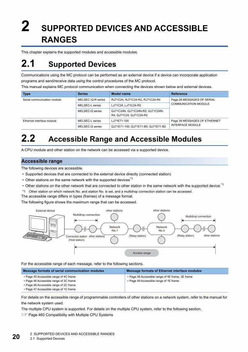
2.2 Accessible Range and Accessible ModulesA CPU module and other station on the network can be accessed via a supported device.
Accessible rangeThe following devices are accessible.
• Supported devices that are connected to the external device directly (connected station)
• Other stations on the same network with the supported devices*1
• Other stations on the other network that are connected to other station in the same network with the supported device.*1
*1 Other station on which network No. and station No. is set, and a multidrop connection station can be accessed.
The accessible range differs in types (frames) of a message format.
The following figure shows the maximum range that can be accessed.
For the accessible range of each message, refer to the following sections.
For details on the accessible range of programmable controllers of other stations on a network system, refer to the manual for
the network system used.
The multiple CPU system is supported. For details on the multiple CPU system, refer to the following section.
Page 460 Compatibility with Multiple CPU Systems
Type Series Model name Reference
Serial communication module MELSEC iQ-R series RJ71C24, RJ71C24-R2, RJ71C24-R4 Page 28 MESSAGES OF SERIAL
COMMUNICATION MODULEMELSEC-L series LJ71C24, LJ71C24-R2
MELSEC-Q series QJ71C24N, QJ71C24N-R2, QJ71C24N-
R4, QJ71C24, QJ71C24-R2
Ethernet interface module MELSEC-L series LJ71E71-100 Page 39 MESSAGES OF ETHERNET
INTERFACE MODULEMELSEC-Q series QJ71E71-100, QJ71E71-B5, QJ71E71-B2
Message formats of serial communication modules Message formats of Ethernet interface modules
• Page 45 Accessible range of 4C frame
• Page 46 Accessible range of 3C frame
• Page 46 Accessible range of 2C frame
• Page 47 Accessible range of 1C frame
• Page 48 Accessible range of 4E frame, 3E frame
• Page 49 Accessible range of 1E frame
External device other stations other stationsMultidrop connection Multidrop connection
NetworkNo.1
NetworkNo.n
other stations(Relay station)(Relay station)Connected station(Host station)
other stations
Access range

2 SUPPORTED DEVICES AND ACCESSIBLE RANGES2.2 Accessible Range and Accessible Modules 21
2
Accessible modulesThe following modules in the accessible range can be accessed
However, the commands that can be used have some restrictions. (Page 469 Accessible Modules for Each Command)
For the access to A series and QnA series modules, refer to the following sections.
• For QnA series: Page 284 MELSEC-QnA SERIES SUPPORTED SPECIFICATIONS
• For A series: Page 340 MELSEC-A SERIES SUPPORTED SPECIFICATIONS
For the restrictions for model name and version of the supported module, refer to the manual of each module.
■Connectable modulesThe following modules can be connected from an external device with the serial communication.
• Serial communication module
• CPU modules that have serial communication function
For the serial communication functions, refer to the user's manual of the CPU module used.
MELSEC-L CPU Module User's Manual (Function Explanation, Program Fundamentals)
QnUCPU User's Manual (Function Explanation, Program Fundamentals)
The following modules can be connected from an external device with the Ethernet communication.
• Ethernet interface module
• Built-in Ethernet CPU module
For Ethernet built-in CPU modules, refer to the user's manual of the CPU module used.
MELSEC-L CPU Module User's Manual (Built-In Ethernet Function)
QnUCPU User's Manual (Communication via Built-in Ethernet Port)
■Accessible modules via supported deviceThe following modules are accessible from the connected station (host station) or other station.
• CPU module
• MELSECNET/H remote I/O station
• CC-Link IE Field Network head module
• Intelligent function module
■Modules that can be relayed between networksThe networks that can be relayed by setting the network No. and station No., and the devices that can be relayed are shown
below.
In the circumstances that multiple network modules with the same network No. are mounted on the station with C24/E71, the
access to other stations is performed via the network module mounted on the slot that has the lowest base unit number when
the network No. is specified.
The following networks are accessible.
• Ethernet (Setting the network No. and station No. are required.)
• CC-Link IE Controller Network
• CC-Link IE Field Network
• MELSECNET/H
Up to 8 connection targets (relay stations: 7 stations) can be accessed.
Network Module type Model name
CC-Link IE Field
Network
CC-Link IE Field Network master/local-equipped
module
RJ71GF11-T2, RJ71EN71 (when using the CC-Link IE Field Network function)
CC-Link IE Field Network master/local module LJ71GF11-T2, QJ71GF11-T2, QS0J71GF11-T2
CC-Link IE Controller
Network
CC-Link IE Controller Network-equipped module RJ71GP21-SX
CC-Link IE Controller Network module QJ71GP21-SX, QJ71GP21S-SX
MELSECNET/H MELSECNET/H module QJ71LP21, QJ71LP21-25, QJ71LP21S-25, QJ71LP21G, QJ71BR11, QJ71NT11B
Ethernet Ethernet interface module RJ71EN71, LJ71E71-100, QJ71E71-100, QJ71E71-B5, QJ71E71-B2, QJ71E71

223 COMMUNICATION PROCEDURE3.1 Features of Communication Process
3 COMMUNICATION PROCEDURE
This chapter explains the considerations when performing communication from an external devices to the programmable
controller system using MC protocol.
3.1 Features of Communication ProcessThe following shows the features of data communication using MC protocol.
Request messages and response messagesThere are two types of messages in MC protocol; request message and response message.
The request message sent from the external device is processed in the CPU module via MC protocol supported devices. The
processing result is returned as a response message to the external device.
Half-duplex communicationData communication by MC protocol is performed with half-duplex communication.*1
When accessing CPU module, send the next command message after receiving the response message against the
previously sent command message from the CPU module. (The command messages cannot be sent until the reception of the
response message is completed.)
When the system between external devices and CPU module is configured with an m:n connection, the next command
message cannot be sent until data communication between either of the external devices and CPU modules is completed.
*1 When using the on-demand function using C24, full-duplex communication can be performed.
External device
Supported device
Execution of the processing.Sending a request message
According to the message sent from the external device, performs the requested processing such asreading or writing.
Sends a request message to the supported device.
Repeated as needed.
Returning a response messageReceiving the response messageReceives the response message from the supported device, and confirms the processing result.
Upon completion of the processing, sends a response message to the external device.
End of the communication
The external device performs end processing to terminate the communication.

3 COMMUNICATION PROCEDURE3.2 Considerations 23
3
3.2 ConsiderationsThe following are the considerations when performing data communication.
When accessing CPU moduleThe following are the considerations when accessing a CPU module from an external device via a supported device.
■Processing timing of CPU module Processing for a request message is performed during an END processing of CPU module.
1. Send a request message from the external device to a supported device.
2. When the request message is received from the external device to the target device, a data read request or write request
is issued to the CPU module.
3. In accordance with the request issued from the external device during END processing from the external device, CPU
modules reads/writes data and then sends the processing result back to the supported device.
4. Once the supported device receives a processing result from the CPU module, send a response message including the
processing result to the external device.
■Read or write data while CPU module is in RUN • Due to process the request from the external device, scan time of the CPU module will be extended. If the extension of the
scan time affects the control, access the CPU module several times with less number of points.
• Before writing, check whether the online change is enabled (such as whether the system protection is unlocked or not) on
the CPU module side.
■When the access target CPU module is protected by system protectionAn error occurs at the access target, and an abnormal response is sent back to the external device. Unlock the system
protection of the CPU module side, and resend the request message.
■When access requests are sent to one station from several external devices at the same timeDepending on the request timing, the processing requested from the external device may be on hold until several END
processing take place. By using either of the following methods, multiple requests can be processed in one scan.
• Execute COM instruction by program.
• Ensure 1 to 100 ms of service processing time using "Service Processing Setting" of Engineering tool.
1.
2. 3.
4.
END END END END
External device External device
Request message Response message
Supported device
Step 0 Step 0
to to to
Step 0 Step 0CPU module
END processing END processing END processing
Processing of the request message from the external device.

243 COMMUNICATION PROCEDURE3.2 Considerations
When accessing MELSECNET/H or MELSECNET/10 remote I/O stationThe following are the considerations when accessing a MELSECNET/H remote I/O station or MELSECNET/10 remote I/O
station from external devices.
■Considerations for supported frames1E frame cannot be used for communication.
■Functions that can be usedThe functions that can be used for remote I/O station are as follows:
*1 The monitoring target devices can be registered within the device range of MELSECNET/H remote I/O station.
Only reading from/writing to the buffer memory of intelligent function module is available for MELSECNET/10 remote I/O
stations supported by QnA/A series.
■When writing dataWhen writing data to the devices of the remote I/O station or intelligent function module mounted on the remote I/O station, set
the setting of online program change to allow with Engineering tool.
(Page 463 Setting method for writing data to CPU during RUN)
■Accessible range of other stationAccessing MELSECNET/H remote master station and MELSECNET/H remote I/O station can be performed from E71 with
MELSECNET/H remote I/O station mounted.
Other station cannot be accessed via a remote I/O station. (A remote I/O station does not work as a relay station.)
Function MELSECNET/H remote I/O station MELSECNET/10 remote I/O station
Read/write device memory
Read/write buffer memory
Read/write intelligent function module
Programmable controller CPU monitoring function (only when C24
is mounted) *1

3 COMMUNICATION PROCEDURE3.2 Considerations 25
3
Considerations when connecting C24The following shows the considerations when performing data communication between C24.
Conditions that C24 transmission sequence becomes initial statusThe transmission sequence of C24 becomes initial status under the following conditions.
• When turning the power ON, changing the status of reset switch on the front of the CPU, and switching modes.
• When the transmission of a response message for the command message reception is completed.
• When a transmission sequence initialization request is received.
• When the CD signal turns OFF while performing data communication by setting the "CD terminal check enable" in the full-
duplex communication of RS-232.
Abnormal response from C24An abnormal response to the external device using MC protocol is issued when an error is detected in the request sent to the
connected station (host station). Therefore, an abnormal response may be issued while sending request from the external
device in the full-duplex communication.
Replacement of other station CPU modules to communicate withC24 imports and retains the information of other station CPU modules after started up.
When replacing the other station CPU module to perform data communication after starting up C24, reboot the C24 if the
model name of the CPU module is changed. (Reset the programmable controller of the connected station (host station)/CPU
reset).
Framing error on external deviceA framing error may occur on the external device when nothing is sent from C24 to the external device via RS-422/485.
Q Corresponding Serial Communication Module User's Manual (Basic)
MELSEC-L Serial Communication Module User's Manual (Basic)
MELSEC iQ-R Serial Communication Module User's Manual(Application)
Skip reading data until C24 sends either STX, ACK, or NAK on the external device.
Before the data communication, check the C24 interface specification written in the following manuals.
Q Corresponding Serial Communication Module User's Manual (Basic)
MELSEC-L Serial Communication Module User's Manual (Basic)
MELSEC iQ-R Serial Communication Module User's Manual(Startup)
Installation of multiple C24sWhen multiple external devices that are connected to each C24 request access to the CPU module at the same time, the
CPU module decides the order of access.
The access priority order cannot be set by user.

263 COMMUNICATION PROCEDURE3.2 Considerations
Considerations when connecting E71
Send of request messageBefore sending a request message, check that the supported device is ready to receive the request message.
When sending multiple request messagesFor 4E frame, send the request message with appending "Serial No." to the subheader on the external device. By appending
"Serial No.", the send source can be identified when multiple request messages have been sent.
When sending request message continuously When sending request messages consecutively without waiting for the reception of the response message using 4E frame,
make sure that the number of command messages shown below are not exceeded.
*1 If the calculation result became decimal, the number after the decimal points will be rounded off to positive number.
When exceeded number of commands were sent, an error may occur in the supported device, or response messages may
not be returned from the supported device.
When sending the request message which exceeds the number of commands, decrease the frequency of request message
transmission.
When the response message corresponding to the request message does not returnIf the response message is not returned from the supported device, resend the request message from the external device
after the specified time set with "Monitoring timer" of the request message is elapsed.
Replacement of devicesAfter replacing a device on Ethernet due to failure, the devices may not communicate properly because of the change of the
MAC address. (When replaced with the device that has the same IP address)
When a device in the Ethernet network is replaced, restart all devices in the network.
Name Model name Applicable number of commands for processing per one connection*1
Ethernet interface module QJ71E71-100,
LJ71E71-100
1 + (57 Number of connections to be used)
QJ71E71-B2,
QJ71E71-B5
1 + (10 Number of connections to be used)
CPU module Q03UDVCPU,
Q04UDVCPU,
Q06UDVCPU,
Q13UDVCPU,
Q26UDVCPU
1 + (Number of messages that can be stored in receive buffer (576) Number of connections to be
used)

27
PA
RT
2
PART 2 MESSAGE FORMATS
This part explains the message format of MC protocol.
4 MESSAGES OF SERIAL COMMUNICATION MODULE
5 MESSAGES OF ETHERNET INTERFACE MODULE
6 ACCESS ROUTE SETTINGS

284 MESSAGES OF SERIAL COMMUNICATION MODULE4.1 Types and Purposes of Messages
4 MESSAGES OF SERIAL COMMUNICATION MODULE
This section explains the specifications of the messages of MC protocol and access range when connecting with serial
communication from an external device.
4.1 Types and Purposes of MessagesThe messages of MC protocol can be classified as shown in the following table depending on the supported device and its
intended purpose.
Formats and codesThere are five formats for the message that can be used for serial communication module.
Set the format with the communication protocol setting of Engineering tool.
Communication using binary code shorten the communication time since the amount of communication data
is reduced by approximately half as compared to the one using ASCII code.
FrameThis section explains the types and purposes of the frames (data communication messages) used by the external device to
access the supported devices using MC protocol.
The frames for serial communication modules are as follows:
Setting value Format Code of communication data Remarks Reference
1 Format 1 ASCII code Page 29 Format 1
2 Format 2 ASCII code Format with block number appended Page 30 Format 2
3 Format 3 ASCII code Format enclosed with STX and ETX Page 31 Format 3
4 Format 4 ASCII code Format with CR and LF appended at the end Page 32 Format 4
5 Format 5 Binary code Can be used by 4C frame. Page 33 Format 5
Frame Features and purposes Compatible message format Format
4C frame Accessible from external devices with the maximum
access range.
Dedicated protocols for MELSEC-QnA series serial
communication modules (QnA extension frame).
Formats 1 to 5
3C frame These message formats are simplified compared to the
4C frame.
Data communication software for MELSEC-QnA series
programmable controllers can be used.
Dedicated protocols for MELSEC-QnA series serial
communication modules (QnA frame).
Formats 1 to 4
2C frame Dedicated protocols for MELSEC-QnA series serial
communication modules (QnA simplified frame).
1C frame These frames have the same message structures as
when accessing the CPU module using an MELSEC-A
series computer link module.
Data communication software for MELSEC-A series
programmable controllers can be used.
Dedicated protocols for MELSEC-A series computer link
modules

4 MESSAGES OF SERIAL COMMUNICATION MODULE4.2 Message Formats of Each Protocol 29
4
4.2 Message Formats of Each ProtocolThis section explains the message format and setting data per each format.
Format 1
Message format
■Request message
■Response message (Normal completion: Response data)
■Response message (Normal completion: No response data)
■Response message (Abnormal completion)
Setting dataSet the following items.
Item Description Reference
Control code
(ENQ, STX, ACK, NAK, ETX)
A code is defined for control. Page 34 Control code
Frame ID No. Specify the frame to be used. Page 36 Frame ID No.
Access route Specify the access route. Page 45 ACCESS ROUTE
SETTINGS
Request data Set the command that indicates the request content. Refer to "Request
data" rows of each command.
Page 60 COMMANDS AND
FUNCTIONS
Response data Store the read data for the command. Refer to "Response data" rows of
each command.
Sum check code The value of the lower one byte (8 bits) of the additional result regarding
the data in the sum check target range as a binary data.
Page 36 Sum check code
Error code Error code indicates the content of occurred error. Page 38 Error code
ENQ05H
Control codeFrame ID No. Access route Request data Sum check code
Sum check range
STX02H
ETX03H
Control codeControl codeSum check codeFrame ID No. Access route Response data
Sum check range
06HACK
Control codeFrame ID No. Access route
15HNAK
Control codeFrame ID No. Access route Error code

304 MESSAGES OF SERIAL COMMUNICATION MODULE4.2 Message Formats of Each Protocol
Format 2
Message format
■Request message
■Response message (Normal completion: Response data)
■Response message (Normal completion: No response data)
■Response message (Abnormal completion)
Setting dataSet the following items.
Item Description Reference
Control code
(ENQ, STX, ACK, NAK, ETX)
A code is defined for control. Page 34 Control code
Block number This can set arbitrarily in the range of '00H' to 'FFH'.
It is used for data defragmentation.
Page 36 Block number
Frame ID No. Specify the frame to be used. Page 36 Frame ID No.
Access route Specify the access route. Page 45 ACCESS ROUTE
SETTINGS
Request data Set the command that indicates the request content. Refer to "Request
data" rows of each command.
Page 60 COMMANDS AND
FUNCTIONS
Response data Store the read data for the command. Refer to "Response data" rows of
each command.
Sum check code The value of the lower one byte (8 bits) of the additional result regarding
the data in the sum check target range as a binary data.
Page 36 Sum check code
Error code Error code indicates the content of occurred error. Page 38 Error code
ENQ05H
Control codeBlock No. Frame ID No. Access route Request data Sum check code
Sum check range
STX02H
ETX03H
Control codeControl codeBlock No. Frame ID No. Access route Response data Sum check code
Sum check range
ACX06H
Control codeBlock No. Frame ID No. Access route
NAK15H
Control codeControl codeBlock No.Block No. Frame ID No.Frame ID No. Access routeAccess route Error codeError code
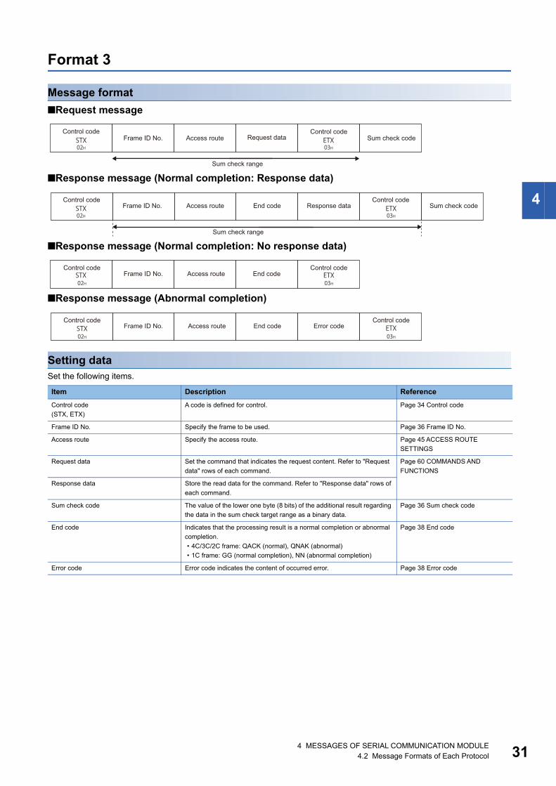
4 MESSAGES OF SERIAL COMMUNICATION MODULE4.2 Message Formats of Each Protocol 31
4
Format 3
Message format
■Request message
■Response message (Normal completion: Response data)
■Response message (Normal completion: No response data)
■Response message (Abnormal completion)
Setting dataSet the following items.
Item Description Reference
Control code
(STX, ETX)
A code is defined for control. Page 34 Control code
Frame ID No. Specify the frame to be used. Page 36 Frame ID No.
Access route Specify the access route. Page 45 ACCESS ROUTE
SETTINGS
Request data Set the command that indicates the request content. Refer to "Request
data" rows of each command.
Page 60 COMMANDS AND
FUNCTIONS
Response data Store the read data for the command. Refer to "Response data" rows of
each command.
Sum check code The value of the lower one byte (8 bits) of the additional result regarding
the data in the sum check target range as a binary data.
Page 36 Sum check code
End code Indicates that the processing result is a normal completion or abnormal
completion.
• 4C/3C/2C frame: QACK (normal), QNAK (abnormal)
• 1C frame: GG (normal completion), NN (abnormal completion)
Page 38 End code
Error code Error code indicates the content of occurred error. Page 38 Error code
STX02H
ETX03H
Control code Control codeRequest dataFrame ID No. Access route Sum check code
Sum check range
STX02H
ETX03H
Control code Control codeFrame ID No. Access route End code Response data Sum check code
Sum check range
02H 03HSTX ETX
Control code Control codeFrame ID No. Access route End code
02H 03HSTX ETX
Control code Control codeFrame ID No. Access route End code Error code

324 MESSAGES OF SERIAL COMMUNICATION MODULE4.2 Message Formats of Each Protocol
Format 4
Message format
■Request message
■Response message (Normal completion: Response data)
■Response message (Normal completion: No response data)
■Response message (Abnormal completion)
Setting dataSet the following items.
Item Description Reference
Control code
(ENQ, STX, ACK, NAK, ETX, CR, LF)
A code is defined for control. Page 34 Control code
Frame ID No. Specify the frame to be used. Page 36 Frame ID No.
Access route Specify the access route. Page 45 ACCESS ROUTE
SETTINGS
Request data Set the command that indicates the request content. Refer to "Request
data" rows of each command.
Page 60 COMMANDS AND
FUNCTIONS
Response data Store the read data for the command. Refer to "Response data" rows of
each command.
Sum check code The value of the lower one byte (8 bits) of the additional result regarding
the data in the sum check target range as a binary data.
Page 36 Sum check code
Error code Error code indicates the content of occurred error. Page 38 Error code
CR0DH
LF0AH
ENQ05H
Control codeControl codeFrame ID No. Access route Request data Sum check code
Sum check range
STX02H
ETX03H
CR0DH
LF0AH
Control code Control codeControl codeSum check codeFrame ID No. Access route Response data
Sum check range
ACK06H
CR0DH
LF0AH
Control codeControl codeFrame ID No. Access route
15H 0DH 0AHNAK CR LF
Control codeControl codeFrame ID No. Access route Error code

4 MESSAGES OF SERIAL COMMUNICATION MODULE4.2 Message Formats of Each Protocol 33
4
Format 5
Message format
■Request message
■Response message (Normal completion: Response data)
■Response message (Normal completion: No response data)
■Response message (Abnormal completion)
Setting dataSet the following items.
Item Description Reference
Control code
(DLE, STX, ETX)
A code is defined for control. Page 34 Control code
Number of data bytes A number of bytes from a frame ID No. to control code (DLE, ETX). Page 35 Number of data bytes
Frame ID No. Specify the frame to be used. Page 36 Frame ID No.
Access route Specify the access route. Page 45 ACCESS ROUTE
SETTINGS
Request data Set the command that indicates the request content. Refer to "Request data" rows of each
command.
Page 60 COMMANDS AND
FUNCTIONS
Response data Store the read data for the command. Refer to "Response data" rows of each command.
Sum check code The value of the lower one byte (8 bits) of the additional result regarding the data in the sum
check target range as a binary data.
Page 36 Sum check code
Response ID code This indicates a response message. The 2-byte numerical value, 'FFFFH' is stored.
Normal completion code This indicates the processing is completed normally. The 2-byte value, '0000H' is stored.
Error code Error code indicates the content of occurred error. Page 38 Error code
DLE10H
STX02H
DLE10H
ETX03HF8H
FrameID No.
Control codeControl code Number of data bytes
Access route Requestdata Sum check code
Specify the number of bytes in this range.
Sum check range
DLE10H
STX02H
DLE10H
ETX03HF8H FFFFH 0000H
FrameID No.
ResponseID code
Normal completion
codeControl codeControl code Number of
data bytesAccess route Response
data Sum check code
Specify the number of bytes in this range.
Sum check range
DLE10H
STX02H
DLE10H
ETX03HF8H FFFFH 0000H
FrameID No.
ResponseID code
Normal completion
codeControl codeControl code Number of
data bytesAccess route Sum check code
Specify the number of bytes in this range.
Sum check range
DLE10H
STX02H
DLE10H
ETX03HF8H FFFFH
FrameID No.
ResponseID code
Control codeControl code Number of data bytes
Access route Errorcodes Sum check code
Specify the number of bytes in this range.
Sum check range

344 MESSAGES OF SERIAL COMMUNICATION MODULE4.3 Details of Setting Data
4.3 Details of Setting DataThis section explains how to specify the common data items and their content in each message.
Control codeControl code is a data that has special meaning (such as head data of a message) for C24 transmission control.
Control code used in a message (format 1 to format 4) in ASCII codeThe control code used for a message in ASCII code (format 1 to format 4) is shown in the following table.
■EOT(04H), CL(0CH)EOT and CL are codes for initializing the transmission sequence for data communications in ASCII code using the MC
protocol and for placing C24 into wait state to receive commands from an external device.
The transmission sequence is initialized with the command (command code: 1615) when binary code (format 5) is used.
When performing the following at an external device, send the EOT/CL to the C24 depending on the format used.
• Canceling a read/write request by command previously sent. (If a write request is issued, the write request cannot be
canceled when the data has already written to the CPU module.)
• Placing C24 into the wait state to receive commands before commands are sent.
• Placing C24 into the state where it has been started up when data communication cannot be performed normally.
The message structure when sending EOT, CL is shown below.
Only the following data is sent. The station No. and PC No. are not required.
When C24 receives EOT or CL, it proceeds as follows.
• C24 terminates any read/write processing performed to the CPU module upon request from the external device. In this
case, C24 does not send a response message to the command previously received.
• C24 initializes the transmission sequence of the MC protocol from which the EOT/CL is received on the interface side and
placing C24 into wait state to receive commands from an external device.
• C24 does not send a response message to the EOT or CL reception. (It does not send anything to external devices.)
• When it receives EOT or CL while the on-demand function (data transmission function from the CPU module to external
devices) is being performed, C24 terminates to transmit the on-demand data to external devices. (Page 278 On-
demand function)
Symbol name Description Code (hexadecimal)
STX Start of Text 02H
ETX End of Text 03H
EOT End of Transmission 04H
ENQ Enquiry 05H
ACK Acknowledge 06H
LF Line Feed 0AH
CL Clear 0CH
CR Carriage Return 0DH
NAK Negative Acknowledge 15H
Format EOT CL
Format 1 to format 3
Format 4
EOT04H
CL0CH
EOT04H
CR0DH
LF0AH
CL0CH
CR0DH
LF0AH

4 MESSAGES OF SERIAL COMMUNICATION MODULE4.3 Details of Setting Data 35
4
Control code used in a message (format 5) in binary code The control code used for a message in binary code (format 5) is shown in the table below.
■Additional code (10H)The additional code is added to distinguish the data when the control code DLE (10H) is the same as the setting data in the
frame 5.
When '10H' is included in the data from "Number of data bytes" and "Request data" in the request message, the additional
code '10H' is added in front of the data.
When '10H' is included in the data from "Number of data bytes" and "Response data" in the response message, the additional
code '10H' is added.
('10H' is transmitted as '10H' + '10H'.)
Calculate the following value except for the additional code.
• Number of data bytes (setting item of format 5)
• Sum check code
Number of data bytesA number of data bytes indicates the total number of bytes from the frame ID No. to control code.
RangeCalculate the data in the range from frame ID No. before DLE (10H) except for the additional code. (Page 35 Additional
code (10H))
Setting methodSet the data in binary code (format 5) at data communication.
Send 2-byte numerical value from the lower byte (L: bits 0 to 7).
Ex.
Response message (Normal completion: Response data)
• Frame ID No.: 1 byte
• Access route: 7 byte
• Response ID code, normal completion code: 4 bytes
• Response data: 2 bytes + additional code (10H) 1 byte
Number of data bytes = 1 + 7 + 4 + 2 = 14 (0EH)
Symbol name Description Code (hexadecimal)
STX Start of Text 02H
ETX End of Text 03H
DLE Data Link Escape 10H
DLE10H
STX02H
DLE10H
ETX03HF8H
FrameID No.
Control codeControl code Number of data bytes Sum check code
Specify the number of bytes in this range.
DLE10H
STX02H
DLE10H
ETX03HF8H FFFFH0E00H 0000H 001010H
FrameID No.
Access route ResponseID code
Normal completion
code
Responsedata
Number of data bytes
Control codeControl codeSum check code
( 7 bytes )
Specify the number of bytes in this range.

364 MESSAGES OF SERIAL COMMUNICATION MODULE4.3 Details of Setting Data
Block numberBlock number is an arbitrary number defined by an external device and used for data defragmentation.
Block number converts data to 2-digit (hexadecimal) ASCII code within the range of '00H' to 'FFH' and sent them from the
upper digits.
C24 only checks if the block number is specified within the correct range. It does not check whether the block numbers are
sent in order.
Frame ID No.Specify the frame to be used.
Setting method
■Data communication in ASCII codeConvert the numerical value to 2-digit ASCII code (hexadecimal), and send it from the upper digits.
■Data communication in binary codeSend a 1-byte numerical value.
Ex.
For 4C frame (F8)
Sum check codeSet the sum check code when performing sum check.
For sum check code, set the value to be calculated from the data with the range of sum check for error detection.
Sum checkSum check is a function for detecting error when data changes while data transmission.
Set the sum check existence by Engineering tool.
■When sum check code is set to "Exist"Attach a sum check code to the request message.
C24 checks the sum check code. The sum check code is added to the response message.
■When sum check code is set to "None"The sum check code is not required for the request message.
C24 does not check the sum check code. The sum check code is not added to the response message.
Type Setting value
4C frame F8
3C frame F9
2C frame FB
1C frame (Not required)
ASCII code Binary code
F 846H 38H F8H

4 MESSAGES OF SERIAL COMMUNICATION MODULE4.3 Details of Setting Data 37
4
Sum check rangeThe sum check range of each message format is as follows:
Calculation of a sum check code For sum check code, set the numerical values of the lower 1 byte (8 bits) of the added result (sum) as binary data within the
sum check range.
Calculate sum check code except for the additional code. (Page 35 Additional code (10H))
Ex.
In the following case of 1C frame format 1, the sum check code will be 'C0'.
Formula: 30H + 30H + 46H + 46H + 42H + 52H + 33H + 4DH + 30H + 30H + 30H + 30H = 2C0H
Sum check code: 'C0' (ASCII code 43H, 30H)
In the following case of 4C frame format 5, the sum check code will be '05'.
Formula: 12H + 00H + F8H + 05H + 07H + 03H + 04H + 00H + 01H + 00H + 01H + 04H + 01H + 00H + 40H + 00H + 00H +
9CH + 05H + 00H = 205H
Sum check code: '05' (ASCII code 30H, 35H)
Format Message structure Reference
Format 1 to format 3 Page 29 Format 1
Page 30 Format 2
Page 31 Format 3
Format 4 Page 32 Format 4
Format 5 Page 33 Format 5
Control code Sum check code
Sum check range
CR0DH
LF0AH
Control codeControl code Sum check code
Sum check range
DLE10H
ETX03H
Control codeControl code Sum check code
Sum check range
05H 30H 30H 46H 46H 42H 52H 33H 4DH 30H 30H 30H 30H 43H 30H
00 F F B R M 0 0 0 C 00 3
ENQ S
tatio
n N
o.
PC
No.
Com
man
d
Mes
sage
wai
t
Char
acte
r ar
ea
Sum
chec
kco
de
Sum check range
10H 02H 12H 00H F8H 05H 07H 03H 04H 00H 01H 00H 01H 04H 01H 00H 40H 00H 00H 9CH 05H 00H 10H 03H 30H 35H
L HL H L H L H - L LH HL H
DLE
STX
DLE
ETX
Sub
com
man
d
Num
ber o
f da
ta b
ytes
Fram
e ID
No.
Sta
tion
No.
PC
No.
Net
wor
k No.
Requ
est d
estin
atio
n m
odul
e I/O
No.
Requ
est d
estin
atio
nm
odul
e St
atio
n No
.
Sel
f-sta
tion
No.
Com
man
d
Hea
d de
vice
Dev
ice
code
Num
ber o
f dev
icepo
ints
Sum
che
ck C
ode
Sum check range (excluding additional codes)
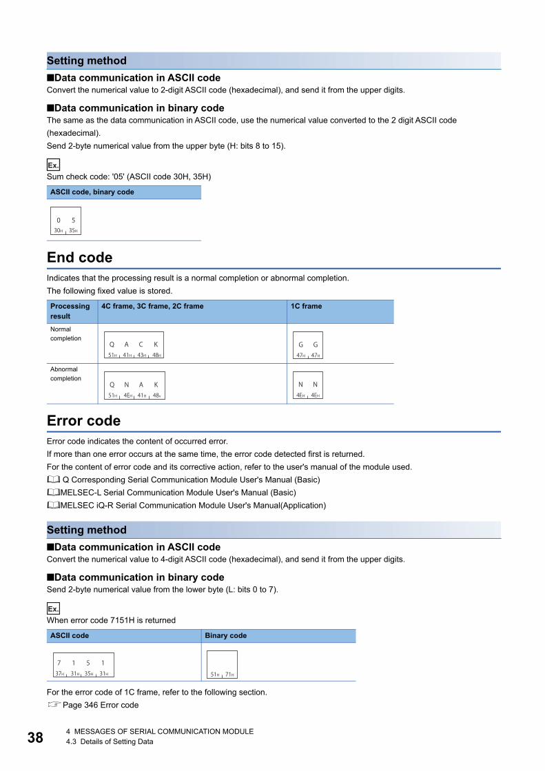
384 MESSAGES OF SERIAL COMMUNICATION MODULE4.3 Details of Setting Data
Setting method
■Data communication in ASCII codeConvert the numerical value to 2-digit ASCII code (hexadecimal), and send it from the upper digits.
■Data communication in binary codeThe same as the data communication in ASCII code, use the numerical value converted to the 2 digit ASCII code
(hexadecimal).
Send 2-byte numerical value from the upper byte (H: bits 8 to 15).
Ex.
Sum check code: '05' (ASCII code 30H, 35H)
End codeIndicates that the processing result is a normal completion or abnormal completion.
The following fixed value is stored.
Error codeError code indicates the content of occurred error.
If more than one error occurs at the same time, the error code detected first is returned.
For the content of error code and its corrective action, refer to the user's manual of the module used.
Q Corresponding Serial Communication Module User's Manual (Basic)
MELSEC-L Serial Communication Module User's Manual (Basic)
MELSEC iQ-R Serial Communication Module User's Manual(Application)
Setting method
■Data communication in ASCII codeConvert the numerical value to 4-digit ASCII code (hexadecimal), and send it from the upper digits.
■Data communication in binary codeSend 2-byte numerical value from the lower byte (L: bits 0 to 7).
Ex.
When error code 7151H is returned
For the error code of 1C frame, refer to the following section.
Page 346 Error code
ASCII code, binary code
Processing result
4C frame, 3C frame, 2C frame 1C frame
Normal
completion
Abnormal
completion
ASCII code Binary code
0 530H 35H
Q51H
A41H
C43H
K48H
G47H
G47H
Q51H
N4EH
A41H
K48v
N4EH
N4EH
737H
131H
535H
131H 51H 71H

5 MESSAGES OF ETHERNET INTERFACE MODULE5.1 Types and Purposes of Messages 39
5
5 MESSAGES OF ETHERNET INTERFACE MODULE
This section explains the specifications of the messages and access range of MC protocol when connecting with Ethernet
communication from an external device.
5.1 Types and Purposes of MessagesThe messages of MC protocol can be classified as shown in the following table depending on the supported device and its
intended purpose.
CodeASCII code and binary code are available.
Set the operation settings with Engineering tool.
Communication using binary code shorten the communication time since the amount of communication data
is reduced by approximately half as compared to the one using ASCII code.
Data storage orderThe data size and the storing order of values for data in each item vary between ASCII code and binary code.
■Data communication in ASCII codeData is stored in order from the upper byte to the lower byte.
■Data communication in binary codeData is stored in order from the lower byte to the upper byte.
Ex.
Subheader of 4E frame request message (serial No. is '1234')
ASCII code Binary code
35H 34H 30H 30H
5 4 0031H 32H 33H 34H
1 2 4330H 30H 30H 30H
0 0 00
Serial number
(Fixed value) (Fixed value)54H 00H 34H 12H 00H 00H
Serial number
(Fixed value)(Fixed value)

405 MESSAGES OF ETHERNET INTERFACE MODULE5.1 Types and Purposes of Messages
FrameThis section explains the types and purposes of the frames (data communication messages) used by the external device to
access the supported devices using MC protocol.
The frames for Ethernet interface modules are as follows:
Frame Features and purposes Compatible message format Correspondence code
4E frame A message format that a "Serial No." (arbitrary number
for message identification) is added to 3E frame. By
appending a "Serial No.", the send source can be
identified when multiple request messages have been
sent.
Message formats for SLMP ASCII code
Binary code
3E frame These frames have the same message structures as
when accessing the CPU module using MELSEC-QnA
series Ethernet interface module.
Data communication software for MELSEC-QnA series
programmable controllers can be used.
Message formats for SLMP
Message formats for MELSEC-QnA series Ethernet interface
modules
ASCII code
Binary code
1E frame These frames have the same message structures as
when accessing the CPU module using an MELSEC-A
series Ethernet interface module.
Data communication software for MELSEC-A series
programmable controllers can be used.
Message formats for MELSEC-A series Ethernet interface
modules
ASCII code
Binary code

5 MESSAGES OF ETHERNET INTERFACE MODULE5.2 Message Format 41
5
5.2 Message FormatThis section explains the message format and setting data for 4E frame and 3E frames.
For the message format for 1E frame, refer to the following section.
Page 389 Message Format
Message format
■Request message
■Response message (Normal completion: Response data)
■Response message (Normal completion: No response data)
■Response message (Abnormal completion)
Setting dataSet the following items.
Item Description Reference
Header A header of Ethernet. Normally, it is added automatically. Page 42 Header
Subheader The value to be set according to type of message is defined.
• 4E frame: Set a serial No.
• 3E frame: Fixed value (Request message '5000', Response message 'D000')
Page 42 Subheader
Access route Specify the access route. Page 45 ACCESS ROUTE SETTINGS
Request data
length
Specify the data length from the monitoring timer to the request data. Page 43 Request data length and
response data length
Monitoring timer Set the wait time up to the completion of reading and writing processing. Page 43 Monitoring timer
Request data For the request data, set the command that indicates the request content. Refer to "Request
data" rows of each command.
Page 60 COMMANDS AND
FUNCTIONS
Response data
length
The data length from an end code to a response data (at normal completion) or an error
information (at abnormal completion) is stored.
Page 43 Request data length and
response data length
Response data For the response data, store the read data for the command at normal completion. Refer to
"Response data" rows of each command.
Page 60 COMMANDS AND
FUNCTIONS
End code The command processing result is stored. Page 44 End code
Error information Store the information of a station on which an error occurred and information of a command. Page 44 Error information
Header Subheader Access route Request data length Monitoring timer Request data
Specify the number of bytes in this range.
Header Subheader Access routeResponse data length End code Response data
Specify the number of bytes in this range.
Header Subheader Access route Response data length End code
Specify the number of bytes of the end code.
Header Subheader Access route Response data length
End code Error information
Specify the number of bytes in this range.

425 MESSAGES OF ETHERNET INTERFACE MODULE5.3 Details of Setting Data
5.3 Details of Setting DataThis section explains how to specify the common data items and their content in each message.
For the setting data with 1E frame, refer to the following section.
Page 389 Details of Setting Data
HeaderA header for TCP/IP and UDP/IP. A header of a request message is added on the external device side and sent. Normally, it
is added automatically by an external device. A header for a response message is set automatically by E71.
SubheaderThe value to be set according to type of message is defined.
Setting method for 4E frameSet the fixed value (request message: '5400', response message: 'D400') and a serial No. (0000H to FFFFH).
A serial No. is an arbitrary number that is added on the external device side for message recognition. When a request
message is sent with a serial No. added, the same serial No. is added to the response message. Use a serial No. when
transmitting more than one request messages from an external device to the same supported device.
Serial No. added on the external device side must be managed at the external device side.
■Data communication in ASCII codeIt's 12 bytes in total.
A fixed value is set by 4-digit ASCII code.
For the serial No., convert the numerical value to 4-digit ASCII code (hexadecimal), and send it from the upper digits.
The 4-byte '0' (30H) is inserted after the serial No.
■Data communication in binary codeIt's 6 bytes in total.
A fixed value is set in 2 bytes.
For the serial No., send 2-byte numerical value from the lower byte (L: bits 0 to 7).
The 2-byte '0' (00H) is inserted after the serial No.
Ex.
Request message (serial No. '1234')
Setting method for 3E frameSet the fixed value (request message: '5000', response message: 'D000').
Request message
ASCII code Binary code
ASCII code Binary code
5 4 00 1 2 43 0 0 0035H 34H 30H 30H 31H 32H 33H 34H 30H 30H 30H 30H
Serial number
(Fixed value) (Free)54H 00H 34H 12H 00H 00H
Serial number
(Free)(Fixed value)
35H 30H 30H 30H
5 0 0050H 00H

5 MESSAGES OF ETHERNET INTERFACE MODULE5.3 Details of Setting Data 43
5
Response message
Request data length and response data lengthFor the request data length, specify the data length from the monitoring timer to the request data.
For the response data length, the data length from an end code to a response data (at normal completion) or an error
information (at abnormal completion) is stored.
Setting methodSpecify the data length in hexadecimal. (Unit: byte)
■Data communication in ASCII codeConvert the numerical value to 4-digit ASCII code (hexadecimal), and send it from the upper digits.
■Data communication in binary codeSend 2-byte numerical value from the lower byte (L: bits 0 to 7).
Ex.
The data length is 24 bytes
Monitoring timerSet the wait time up to the completion of reading and writing processing.
Set the wait time from when E71 on the connection station requests processing to the access target to when the response is
returned.
• 0000H (0): Wait infinitely (Waits until a processing is completed.)
• 0001H to FFFFH (1 to 65535): Waiting time (unit: 250 ms)
To perform normal data communication, using the timer within the setting range in the table below is recommended depending
on the communication destination.
Setting method
■Data communication in ASCII codeConvert the numerical value to 4-digit ASCII code (hexadecimal), and send it from the upper digits.
■Data communication in binary codeSend 2-byte numerical value from the lower byte (L: bits 0 to 7).
Ex.
When specifying 10H (16 250 ms = 4 seconds) for the monitoring timer
ASCII code Binary code
ASCII code Binary code
Access target Monitoring timer
Connected station (host station) 0001H to 0028H (0.25 s to 10 s)
Other station 0002H to 00F0H (0.5s to 60s)
ASCII code Binary code
44H 30H 30H 30H
D 0 00D0H 00H
30H 30H 31H 38H
0 0 8118H 00H
30H 30H 31H 30H
0 0 0110H 00H

445 MESSAGES OF ETHERNET INTERFACE MODULE5.3 Details of Setting Data
End codeThe command processing result is stored.
At normal completion, '0' is stored.
At abnormal completion, an error code of the access target is stored.
Error code indicates the content of occurred error.
If more than one error occurs at the same time, the error code detected first is returned.
For the content of error code and its corrective action, refer to the user's manual of the module used.
QCPU User's Manual (Hardware Design, Maintenance and Inspection)
MELSEC-L CPU Module User's Manual (Hardware Design, Maintenance and Inspection)
Q Corresponding Ethernet Interface Module User's Manual (Basic)
MELSEC-L Ethernet Interface Module User's Manual (Basic)
MELSEC iQ-R Serial Communication Module User's Manual(Application)
Setting method
■Data communication in ASCII codeConvert the numerical value to 4-digit ASCII code (hexadecimal), and send it from the upper digits.
■Data communication in binary codeSend 2-byte numerical value from the lower byte (L: bits 0 to 7).
Ex.
Normal completion
Error code C051H
Error informationStore the information of a station on which an error occurred and information of a command.
• Access route: The information of a station which sent an error response is stored. It may differ from the contents of a
request message.
• Command, subcommand: The command and the subcommand when an error occurred are stored.
ASCII code Binary code
ASCII code Binary code
30H 30H 30H 30H
0 0 0000H 00H
43H 30H 35H 31H
C 0 1551H C0H
Access route Command Subcommand

6 ACCESS ROUTE SETTINGS6.1 Accessible Ranges and Setting Data for Each Frame 45
6
6 ACCESS ROUTE SETTINGS
This chapter explains the accessible range of each frame of MC protocol and data to specify the access target.
6.1 Accessible Ranges and Setting Data for Each Frame
The accessible range of each frame and the data items to set an access route are as shown below.
4C frame
Accessible range of 4C frameThe following ranges can be accessed.
4C frame is supported by multiple CPU system. (Page 460 Compatibility with Multiple CPU Systems)
Message format (Setting example for accessing connected station (host station))
■Data communication in ASCII code (Format 1 to Format 4)
■Data communication in binary code (Format 5)
Setting dataSet the following items.
Item Description Reference
Station No. Specify the station to be connected from an external device. Page 50 Station No.
Network No. Specify the network No. of an access target. Page 52 Network No., PC No.
PC No. Specify the network module station No. of an access target.
Request destination
module I/O No.
• When accessing a multidrop connection station via network, specify the start input/output
number of a multidrop connection source module.
• Specify the CPU module of the multiple CPU system and redundant system.
Page 55 Request destination module
I/O No., request destination module
station No.
Request destination
module station No.
When accessing a multidrop connection station via network, specify the station No. of an
access target module.
Self-station No. At the time of m:n multidrop connection, specify the station No. of a request source external
device.
Page 58 Self-station No.
External deviceMultidrop connection Multidrop connection
NetworkNo.1
NetworkNo.n
(Relay station)Connected station(Host station) :Accessible target station
30H 30H
0 030H 30H
0 046H 46H
F F30H 33H
0 346H 46HF F
30H 30H
0 030H 30H
0 0
NetworkNo.
Request destinationmodule station No.
Request destinationmodule I/O No.
Self-station No.Station No. PC No.
00H 00H FFH FFH 03H 00H 00H
NetworkNo.
Request destinationmodule I/O No.
Request destination module station No.
Self-station No.
PCNo.
StationNo.

466 ACCESS ROUTE SETTINGS6.1 Accessible Ranges and Setting Data for Each Frame
3C frame
Accessible range of 3C frameThe following ranges can be accessed.
Message format (Setting example for accessing connected station (host station))
Setting dataSet the following items.
2C frame
Accessible range of 2C frameThe following ranges can be accessed.
Message format (Setting example for accessing connected station (host station))
Setting dataSet the following items.
Item Description Reference
Station No. Specify the station to be connected from an external device. Page 50 Station No.
Network No. Specify the network No. of an access target. Page 52 Network No., PC No.
PC No. Specify the network module station No. of an access target.
Self-station No. At the time of m:n multidrop connection, specify the station No. of a request source external
device.
Page 58 Self-station No.
Item Description Reference
Station No. Specify the station to be connected from an external device. Page 50 Station No.
Self-station No. At the time of m:n multidrop connection, specify the station No. of a request source external
device.
Page 58 Self-station No.
External device
Multidrop connection
NetworkNo.1
NetworkNo.n
(Relay station)Connected station(Host station)
:Accessible target station
30H 30H
0 030H 30H
0 046H 46H
F F30H 30H
0 0
Network No.Station No. PC No. Self-station No.
External device
Multidrop connection
Connected station(Host station) :Accessible target station
30H 30H
0 030H 30H
0 0
Station No. Self-station No.
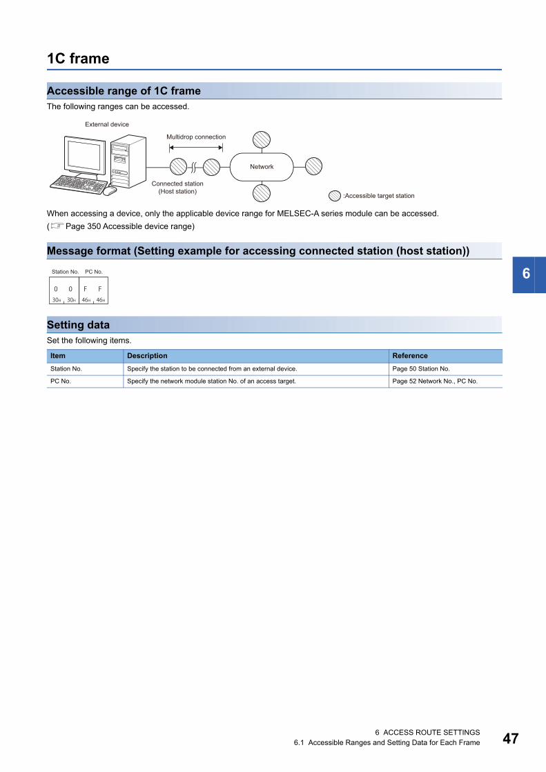
6 ACCESS ROUTE SETTINGS6.1 Accessible Ranges and Setting Data for Each Frame 47
6
1C frame
Accessible range of 1C frameThe following ranges can be accessed.
When accessing a device, only the applicable device range for MELSEC-A series module can be accessed.
(Page 350 Accessible device range)
Message format (Setting example for accessing connected station (host station))
Setting dataSet the following items.
Item Description Reference
Station No. Specify the station to be connected from an external device. Page 50 Station No.
PC No. Specify the network module station No. of an access target. Page 52 Network No., PC No.
External device
Multidrop connection
Network
Connected station(Host station)
:Accessible target station
30H 30H
0 046H 46H
F F
Station No. PC No.

486 ACCESS ROUTE SETTINGS6.1 Accessible Ranges and Setting Data for Each Frame
4E frame, 3E frame
Accessible range of 4E frame, 3E frameThe following ranges can be accessed.
4C frame is supported by multiple CPU system. (Page 460 Compatibility with Multiple CPU Systems)
Message format (Setting example for accessing connected station (host station))
■Data communication in ASCII code
■Data communication in binary code
Setting dataSet the following items.
Item Description Reference
Network No. Specify the network No. of an access target. Page 52 Network No., PC No.
PC No. Specify the network module station No. of an access target.
Request destination
module I/O No.
• When accessing a multidrop connection station, specify the start input/output number of
a multidrop connection source module.
• Specify the CPU module of the multiple CPU system and redundant system.
Page 55 Request destination module
I/O No., request destination module
station No.
Request destination
module station No.
When accessing a multidrop connection station, specify the station No. of an access target
module.
External device
Multidrop connectionConnected station(Host station)
NetworkNo.1
NetworkNo.n
(Relay station)
:Accessible target station
30H 30H
0 046H 46H
F F30H 33H
0 346H 46HF F
30H 30H
0 0
NetworkNo.
Request destinationmodule I/O No.
Request destinationmodule station No.
PC No.
00H FFH FFH 03H 00H
NetworkNo.
Request destinationmodule I/O No.
Request destinationmodule station No.
PCNo.

6 ACCESS ROUTE SETTINGS6.1 Accessible Ranges and Setting Data for Each Frame 49
6
1E Frame
Accessible range of 1E frameThe following ranges can be accessed.
When accessing a device, only the applicable device range for MELSEC-A series module can be accessed.
(Page 397 Accessible device range)
Message format (Setting example for accessing connected station (host station))
■Data communication in ASCII code
■Data communication in binary code
Setting dataSet the following items.
Item Description Reference
PC No. Specify the network module station No. of an access target. Page 52 Network No., PC No.
External device
Connected station(Host station)
Network
:Accessible target station
46H 46H
F F
PC No.
FFH
PC No.

506 ACCESS ROUTE SETTINGS6.2 Details of Setting Data
6.2 Details of Setting DataThis section explains the content and specification method of the data items to set the access route.
: Necessary, : Unnecessary
Station No.Specify the station accessed from an external device.
Accessing the connected station (host station)Specify '0' when accessing the connected station (host station).
Accessing multidrop connection stationSpecify the station No. of an access target station from '0' to '31' (00H to 1FH) when connecting with the multidrop connection.
■When accessing all stations connected with the multidrop connection with the global functionSpecify 'FF' (FFH) when turning ON/OFF the global signal to all station connected with the multidrop connection using the
global function. By specifying 0 to 31 (00H to 1FH), X1A/X1B turns ON only on the specified station, and does not turn ON on
the other stations.
(Page 253 Global Function)
Item Frames for C24 Frames for E71 Reference
4C 3C 2C 1C 4E 3E 1E
Station No. Page 50 Station No.
Network No. Page 52 Network No., PC No.
PC No.
Request destination module I/O No. Page 55 Request destination module I/O No., request
destination module station No.Request destination module station No.
Self-station No. Page 58 Self-station No.
External device
Connected station(Host station) :Access target station
External device
Multidrop connection
:Access target station
External device
Multidrop connection
:Access target station

6 ACCESS ROUTE SETTINGS6.2 Details of Setting Data 51
6
Accessing other stations via networkSpecify the station No. from 0 to 31 (00H to 1FH) of a station that relays multidrop connection and network when accessing
other stations via network.
Specify '0' when accessing other stations via network without the multidrop connection.
Setting method
■Data communication in ASCII codeConvert the numerical value to 2-digit ASCII code (hexadecimal), and send it from the upper digits.
■Data communication in binary codeSend a 1-byte numerical value.
Ex.
When the station No. setting for C24 to be accessed is '5'
When accessing all station connected with the multidrop connection using the global function
The station No. of the serial communication module can be checked by using the following parameters of
Engineering tool.
• GX Works2: "Station Number Setting" in "Switch Setting"
• GX Works3: "Station Number Settings" in "Module Parameter"
ASCII code Binary code
ASCII code Binary code
External device
Multidrop connection
Other stations
Network
(Relay station)Connected station(Host station) :Station specified to the station No.
:Access target station
35H30H50
05H
46H 46H
F FFFH
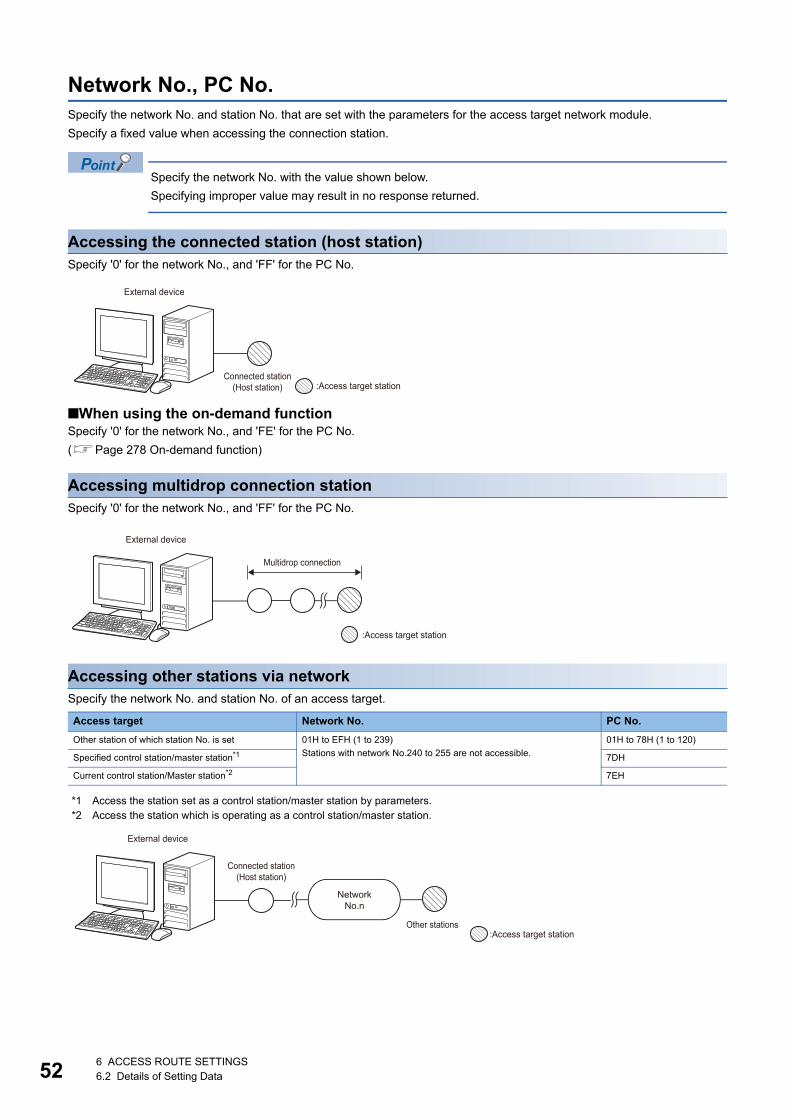
526 ACCESS ROUTE SETTINGS6.2 Details of Setting Data
Network No., PC No.Specify the network No. and station No. that are set with the parameters for the access target network module.
Specify a fixed value when accessing the connection station.
Specify the network No. with the value shown below.
Specifying improper value may result in no response returned.
Accessing the connected station (host station)Specify '0' for the network No., and 'FF' for the PC No.
■When using the on-demand functionSpecify '0' for the network No., and 'FE' for the PC No.
(Page 278 On-demand function)
Accessing multidrop connection stationSpecify '0' for the network No., and 'FF' for the PC No.
Accessing other stations via networkSpecify the network No. and station No. of an access target.
*1 Access the station set as a control station/master station by parameters.*2 Access the station which is operating as a control station/master station.
Access target Network No. PC No.
Other station of which station No. is set 01H to EFH (1 to 239)
Stations with network No.240 to 255 are not accessible.
01H to 78H (1 to 120)
Specified control station/master station*1 7DH
Current control station/Master station*2 7EH
External device
Connected station(Host station) :Access target station
External device
Multidrop connection
:Access target station
NetworkNo.n
:Access target stationOther stations
External device
Connected station(Host station)

6 ACCESS ROUTE SETTINGS6.2 Details of Setting Data 53
6
■When accessing with the "Valid Module During Other Station Access" setting1C frame and 1E frame do not have the setting of network No.
When specifying the network of access target is required because more than one network module is mounted on the
connection station, set the "Valid Module During Other Station Access" with Engineering tool.
When accessing in accordance with the setting of "Valid Module During Other Station Access" using a frame with the network
No. set is desired, specify 'FEH' (254) to the network No.
When accessing other station via C24/E71 mounted on MELSECNET/H remote I/O station, the access to the other station
specified with the PC No. of MELSECNET/H remote I/O station is available by specifying 'FEH' to the network No.
Accessing multidrop connection station via networkSpecify the network No. and station No. of a station relaying the network routed through and multidrop connection station.
Access target Network No. PC No.
Multidrop connection station via network 01H to EFH (1 to 239)
Stations with network No.240 to 255 are not accessible.
01H to 78H (1 to 120)
QX41PQCPU QX41 QX41 QJ71C24 QJ71LP21 QJ71E71-100 QJ71LP21 QJ71LP21
QCPU QJ71LP21Ethernet
Valid module during other station access : 3 1C frame
Power supplymodule
Network No.3
Network No.2
Network No.1Power supply
module
External device
Multidrop connectionConnected station
(Host station)
NetworkNo.n
(Relay station) :Station specified to the network No. and station No.
:Access target station

546 ACCESS ROUTE SETTINGS6.2 Details of Setting Data
Setting method
■Data communication in ASCII codeConvert the numerical value to 2-digit ASCII code (hexadecimal), and send it from the upper digits.
■Data communication in binary codeSend a 1-byte numerical value.
Ex.
Accessing connected station (host station) or multidrop connection station
When accessing other station of which network No. is '2' and station No. is '3'
The network No. and station No. of the network module can be checked by using the following parameters of
Engineering tool.
• GX Works2: "Network Parameter"
• GX Works3: "Module Parameter"
The network No. and the station No. of the network module are normally set in decimal. However, the network
No. and the PC No. are set in hexadecimal.
ASCII code Binary code
ASCII code Binary code
30H 30H 46H 46H
0 0 F F
NetworkNo.
PC No.
00H FFH
NetworkNo.
PCNo.
30H 32H 30H 33H
0 2 0 3
NetworkNo.
PCNo.
02H 03H
NetworkNo.
PCNo.

6 ACCESS ROUTE SETTINGS6.2 Details of Setting Data 55
6
Request destination module I/O No., request destination module station No.Specify these numbers when an access target is as shown below.
• Multidrop connection station
• CPU module on multiple CPU system
• CPU module on redundant system, CC-Link IE Field Network remote head module
Specify the fixed value when the access target is other than those listed above.
Accessing multidrop connection stationWhen connecting to an access target with a direct multidrop connection, it can be accessed by specifying a station No.
(Page 50 Station No.).
For the request destination module I/O No. and the request destination module station No., specify the fixed value.
■For 4E frame and 3E frameWhen accessing a multidrop connection station with the frames (4E frame, 3E frame) for Ethernet interface module, specify
the start input/output number of a multidrop connection source module (relay station) and the station No. of an access target
module.
Request destination module I/O No. Request destination module station No.
03FFH 00H
Request destination module I/O No. Request destination module station No.
03FFH 00H
Access target Request destination module I/O No. Request destination module station No.
MELSEC iQ-R series module 0000H to 02FFH: Values obtained by dividing the start input/output number by 16 00H to 1FH (0 to 31): Station No.
MELSEC-Q/L series module 0000H to 01FFH: Values obtained by dividing the start input/output number by 16
External device
Multidrop connection
:Access target station
External device
Multidrop connectionConnected station(Host station)
:Station specified to the request destination module I/O number
:Access target station(Station specified to the request destination module station No.)
E71 C24

566 ACCESS ROUTE SETTINGS6.2 Details of Setting Data
Accessing multidrop connection station via networkSpecify the start input/output number of a multidrop connection source module (relay station) and the station No. of an access
target.
Accessing multiple CPU system, redundant systemSpecify the access target with the request destination module I/O No. Specify the fixed value (00H) for the station No.
*1 When executing a command that manages files, specify the I/O number other than that of the control system (03D0H) and standby system (03D1H). Otherwise, the access target is changed and the files cannot be read/written.
Access target Request destination module I/O No. Request destination module station No.
MELSEC iQ-R series module 0000H to 02FFH: Values obtained by dividing the start input/output number by 16 00H to 1FH (0 to 31): Station No.
MELSEC-Q/L series module 0000H to 01FFH: Values obtained by dividing the start input/output number by 16
Access target Request destination module I/O No. Request destination module station No.
Multiple CPU system Control CPU 03FFH 00H
Non-control
CPU
Multiple CPU No.1 03E0H
Multiple CPU No.2 03E1H
Multiple CPU No.3 03E2H
Multiple CPU No.4 03E3H
Redundant system CPU module Control system*1 03D0H
Standby system*1 03D1H
System A 03D2H
System B 03D3H
CC-Link IE
Field Network
remote head
module
Remote head No.1 03E0H
Remote head No.2 03E1H
Control system*1 03D0H
Standby system*1 03D1H
External deviceMultidrop connection
Connected station(Host station)
NetworkNo.n :Station specified to the request
destination module I/O number(Relay station) :Access target station
(Station specified to the request destination module station No.)

6 ACCESS ROUTE SETTINGS6.2 Details of Setting Data 57
6
Setting methodFor the request destination module I/O No., specify the value obtained by dividing the start input/output number assigned to
the module by 16 in 4 digits (hexadecimal).
■Data communication in ASCII codeFor the request destination module I/O No., convert the numerical value to 4-digit ASCII code (hexadecimal), and send it from
the upper digits.
For the request destination module station No., convert the numerical value to 2-digit ASCII code (hexadecimal), and send it
from the upper digits.
■Data communication in binary codeFor the request destination module I/O No., the 2-byte value is sent from the lower byte (L: bit 0 to 7).
For the request destination module station No., the 1-byte value is sent.
Ex.
Accessing the connected station (host station)
Accessing multidrop connection station via network
• Start input/output number: 0080H (input/output signal: 0080H to 009FH)
• Request destination module I/O No.: 0008H
• Station No.: 5
The station No. of the serial communication module can be checked by using the following parameters of
Engineering tool.
• GX Works2: "Station Number Setting" in "Switch Setting"
• GX Works3: "Station Number Settings" in "Module Parameter"
When accessing the non-control CPU (multiple CPU No.2) on multiple CPU system
ASCII code Binary code
ASCII code Binary code
ASCII code Binary code
30H 33H 46H 46H 30H 30H
0 3 F F 0 0
Request destinationmodule I/O No.
Request destinationmodule station No.
FFH 03H 00H
Request destinationmodule I/O No.
Request destinationmodule station No.
0 0 0 8 0 5
30H 30H 30H 38H 30H 35H
Request destinationmodule I/O No.
Request destinationmodule station No.
08H 00H 05H
Request destinationmodule I/O No.
Request destinationmodule station No.
30H 33H 45H 31H 30H 30H
0 3 E 1 0 0
Request destinationmodule I/O No.
Request destinationmodule station No.
E1H 03H 00H
Request destinationmodule I/O No.
Request destinationmodule station No.

586 ACCESS ROUTE SETTINGS6.2 Details of Setting Data
Self-station No.Specify this when more than one external device (m stations) and more than one C24s (n stations) are connected with the
multidrop connection.
Specify the fixed value (00H) for any cases other than multidrop connection in a m:n basis.
When external devices are connected with the m:n multidrop connectionSpecify the station No. of request source external device, 0 to 31 (00H to 1FH).
For the station No. (m stations) of external devices, the value which is not set to C24 (n stations) of the multidrop connection
is used.
(The total of 'm' and 'n' is up to 32 stations.)
• Station No. of a request source external device: Specify it to the self-station No.
• Station No. of the connected station C24: Specify it to the station No. (Page 50 Station No.)
Setting method
■Data communication in ASCII codeConvert the numerical value to 2-digit ASCII code (hexadecimal), and send it from the upper digits.
■Data communication in binary codeSend a 1-byte numerical value.
Ex.
For connection other than m:n multidrop connection
For accessing with the m:n multidrop connection
Station No. assigned to a request source external device: 31 (1FH)
ASCII code Binary code
ASCII code Binary code
m:n multidrop connection
External device : Station No. (n + m - 1) < 32Request source external device : Station number specified for the Self-station No.External device : Station No. n
C24:Station number specified for the Station No. C24: Station No.n-1C24: Station No.0
Connected station
0 030H 30H 00H
31H 46H
1 F1FH

59
PA
RT
3
PART 3 COMMAND
This part explains the functions that can be specified by a message of MC protocol and the message format of
request data and message data of each command.
7 COMMANDS AND FUNCTIONS
8 DEVICE ACCESS
9 LABEL ACCESS
10 BUFFER MEMORY ACCESS
11 CONTROL MODULE OPERATION
12 FILE CONTROL
13 SERIAL COMMUNICATION MODULE DEDICATED COMMANDS

607 COMMANDS AND FUNCTIONS7.1 Command List
7 COMMANDS AND FUNCTIONS
This chapter explains the commands of MC protocol.
The functions of a message is defined by each command. The message format for request data and response data varies
with commands. Depending on the type of frame to be used, the specific value is assigned to a command. The value of
command is specified at the head of a request data.
The explanation of each command in Part 3, the message format of request data and response data are explained.
For the message formats other than request data and response data, refer to the following sections.
Page 28 MESSAGES OF SERIAL COMMUNICATION MODULE
Page 39 MESSAGES OF ETHERNET INTERFACE MODULE
7.1 Command ListThe following shows the list of commands.
There are some commands that cannot be executed while the CPU module is in RUN. Refer to the following
section.
Page 462 Applicable Commands for Online Program Change
For details on the number of points processed per communication and modules can be accessed by each
command, refer to the following sections.
Page 464 Number of Processing per One Communication
Page 469 Accessible Modules for Each Command
Request message
Control code Access route Request data
Command
Response message
Control code Access route Response data
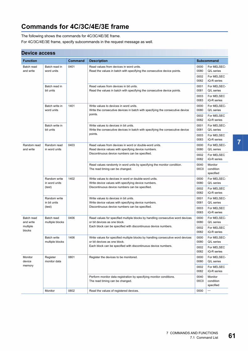
7 COMMANDS AND FUNCTIONS7.1 Command List 61
7
Commands for 4C/3C/4E/3E frameThe following shows the commands for 4C/3C/4E/3E frame.
For 4C/3C/4E/3E frame, specify subcommands in the request message as well.
Device access
Function Command Description Subcommand
Batch read
and write
Batch read in
word units
0401 Read values from devices in word units.
Read the values in batch with specifying the consecutive device points.
0000
0080
For MELSEC-
Q/L series
0002
0082
For MELSEC
iQ-R series
Batch read in
bit units
Read values from devices in bit units.
Read the values in batch with specifying the consecutive device points.
0001
0081
For MELSEC-
Q/L series
0003
0083
For MELSEC
iQ-R series
Batch write in
word units
1401 Write values to devices in word units.
Write the consecutive devices in batch with specifying the consecutive device
points.
0000
0080
For MELSEC-
Q/L series
0002
0082
For MELSEC
iQ-R series
Batch write in
bit units
Write values to devices in bit units.
Write the consecutive devices in batch with specifying the consecutive device
points.
0001
0081
For MELSEC-
Q/L series
0003
0083
For MELSEC
iQ-R series
Random read
and write
Random read
in word units
0403 Read values from devices in word or double-word units.
Read device values with specifying device numbers.
Discontinuous device numbers can be specified.
0000
0080
For MELSEC-
Q/L series
0002
0082
For MELSEC
iQ-R series
Read values randomly in word units by specifying the monitor condition.
The read timing can be changed.
0040
00C0
Monitor
condition
specified
Random write
in word units
(test)
1402 Write values to devices in word or double-word units.
Write device values with specifying device numbers.
Discontinuous device numbers can be specified.
0000
0080
For MELSEC-
Q/L series
0002
0082
For MELSEC
iQ-R series
Random write
in bit units
(test)
Write values to devices in bit units.
Write device values with specifying device numbers.
Discontinuous device numbers can be specified.
0001
0081
For MELSEC-
Q/L series
0003
0083
For MELSEC
iQ-R series
Batch read
and write
multiple
blocks
Batch read
multiple blocks
0406 Read values for specified multiple blocks by handling consecutive word devices
or bit devices as one block.
Each block can be specified with discontinuous device numbers.
0000
0080
For MELSEC-
Q/L series
0002
0082
For MELSEC
iQ-R series
Batch write
multiple blocks
1406 Write values for specified multiple blocks by handling consecutive word devices
or bit devices as one block.
Each block can be specified with discontinuous device numbers.
0000
0080
For MELSEC-
Q/L series
0002
0082
For MELSEC
iQ-R series
Monitor
device
memory
Register
monitor data
0801 Register the devices to be monitored. 0000
0080
For MELSEC-
Q/L series
0002
0082
For MELSEC
iQ-R series
Perform monitor data registration by specifying monitor conditions.
The read timing can be changed.
0040
00C0
Monitor
condition
specified
Monitor 0802 Read the values of registered devices. 0000
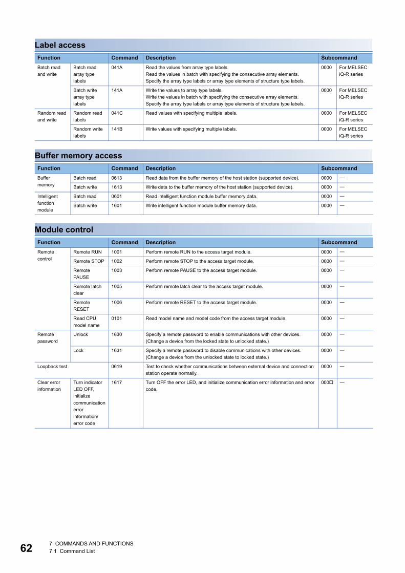
627 COMMANDS AND FUNCTIONS7.1 Command List
Label access
Buffer memory access
Module control
Function Command Description Subcommand
Batch read
and write
Batch read
array type
labels
041A Read the values from array type labels.
Read the values in batch with specifying the consecutive array elements.
Specify the array type labels or array type elements of structure type labels.
0000 For MELSEC
iQ-R series
Batch write
array type
labels
141A Write the values to array type labels.
Write the values in batch with specifying the consecutive array elements.
Specify the array type labels or array type elements of structure type labels.
0000 For MELSEC
iQ-R series
Random read
and write
Random read
labels
041C Read values with specifying multiple labels. 0000 For MELSEC
iQ-R series
Random write
labels
141B Write values with specifying multiple labels. 0000 For MELSEC
iQ-R series
Function Command Description Subcommand
Buffer
memory
Batch read 0613 Read data from the buffer memory of the host station (supported device). 0000
Batch write 1613 Write data to the buffer memory of the host station (supported device). 0000
Intelligent
function
module
Batch read 0601 Read intelligent function module buffer memory data. 0000
Batch write 1601 Write intelligent function module buffer memory data. 0000
Function Command Description Subcommand
Remote
control
Remote RUN 1001 Perform remote RUN to the access target module. 0000
Remote STOP 1002 Perform remote STOP to the access target module. 0000
Remote
PAUSE
1003 Perform remote PAUSE to the access target module. 0000
Remote latch
clear
1005 Perform remote latch clear to the access target module. 0000
Remote
RESET
1006 Perform remote RESET to the access target module. 0000
Read CPU
model name
0101 Read model name and model code from the access target module. 0000
Remote
password
Unlock 1630 Specify a remote password to enable communications with other devices.
(Change a device from the locked state to unlocked state.)
0000
Lock 1631 Specify a remote password to disable communications with other devices.
(Change a device from the unlocked state to locked state.)
0000
Loopback test 0619 Test to check whether communications between external device and connection
station operate normally.
0000
Clear error
information
Turn indicator
LED OFF,
initialize
communication
error
information/
error code
1617 Turn OFF the error LED, and initialize communication error information and error
code.
000

7 COMMANDS AND FUNCTIONS7.1 Command List 63
7
File control
For the QnACPU dedicated commands, refer to the following section.
Page 286 QnACPU Dedicated Commands List
Function Command Description Subcommand
File check Read directory/
file information
1810 For the specified storage destination file, read the file name, file creation date and
time (last edit date and time) etc.
0000 For MELSEC-
Q/L series
0040 For MELSEC
iQ-R series
Search
directory/file
information
1811 Read the file No. of the specified file. 0000 For MELSEC-
Q/L series
0040 For MELSEC
iQ-R series
File creation
and deletion
Create new file 1820 Create a file with specifying its size.
(Reserve a storage area for the specified file.)
0000 For MELSEC-
Q/L series
0040 For MELSEC
iQ-R series
Delete file 1822 Delete a file. 0000 For MELSEC-
Q series
0004 For MELSEC-
L series
0040 For MELSEC
iQ-R series
Copy file 1824 Copy a file. 0000 For MELSEC-
Q series
0004 For MELSEC-
L series
0040 For MELSEC
iQ-R series
File
modification
Modify file
attribute
1825 Change the file attribute. 0000 For MELSEC-
Q series
0004 For MELSEC-
L series
0040 For MELSEC
iQ-R series
Modify file
creation date
and time
1826 Modify the file creation date and time (last edit date and time). 0000 For MELSEC-
Q/L series
0040 For MELSEC
iQ-R series
Open file 1827 Open a file to lock it so that the contents of the file cannot be modified by other
devices.
0000 For MELSEC-
Q series
0004 For MELSEC-
L series
0040 For MELSEC
iQ-R series
Read file 1828 Read a file content. 0000
Write to file 1829 Write content to a file. 0000
Close file 182A Close a file to unlock it by opening file (command: 1827). 0000

647 COMMANDS AND FUNCTIONS7.1 Command List
Serial communication dedicated commands
Commands for 2C frameThe following shows the commands for 2C frame.
The commands for 4C/3C frame are equivalent to the following device access commands and subcommands.
Commands for 1C/1E frameFor the commands for 1C/1E frame, refer to the following sections.
• Page 347 Command and Function Lists for 1C Frame
• Page 394 Commands and Function List for 1E Frame
Function Command Description Subcommand
User frame Read
registered data
0610 Read the contents of registered user frames. 0000
Register data 1610 Register user frames to C24. 0000
Delete
registered data
Delete the registered user frame. 0001
Global 1618 Turn ON/OFF the global signal (X1A/X1B).
This can be performed to a connected station and multidrop connection station.
0000
0001
Initialize transmission sequence 1615 Terminate a current processing request, and place C24 into the wait state to
receive commands.
This can be performed to a connected station and multidrop connection station.
0000
Switch mode 1612 Switch the operation mode and transmission specifications of the specified
interface.
This can be performed to a connected station and multidrop connection station.
0000
Programmable
controller CPU
monitoring
Register 0630 Register the conditions to monitor and start the programmable controller CPU
monitoring.
0000
Deregister 0631 End the programmable controller CPU monitoring. 0000
On-demand 2101 Issue a transmission request to C24 from CPU module, and transmit data to
external devices.
Function 2C framecommand
4C/3C frame Description
command subcommand
Batch
read and
write
Batch read in
bit units
1 0401 0001 Read values from devices in bit units.
Read the values in batch with specifying the consecutive device points.
Batch read in
word units
2 0000 Read values from devices in word units.
Read the values in batch with specifying the consecutive device points.
Batch write in
bit units
3 1401 0001 Write values to devices in bit units.
Write the consecutive devices in batch with specifying the consecutive
device points.
Batch write in
word units
4 0000 Write values to devices in word units.
Write the consecutive devices in batch with specifying the consecutive
device points.
Random
read and
write
Random read
in word units
5 0403 0000 Read values from devices in word or double-word units.
Read device values with specifying device numbers.
Discontinuous device numbers can be specified.
Random write
in bit units
(test)
6 1402 0001 Write values to devices in bit units.
Write device values with specifying device numbers.
Discontinuous device numbers can be specified.
Random write
in word units
(test)
7 0000 Write values to devices in word or double-word units.
Write device values with specifying device numbers.
Discontinuous device numbers can be specified.
Monitor
device
memory
Register
monitor data
8 0801 0000 Register the devices to be monitored.
Monitor 9 0802 0000 Read the values of registered devices.

8 DEVICE ACCESS8.1 Data to be Specified in Commands 65
8
8 DEVICE ACCESS
This chapter explains the commands to read and write devices.
8.1 Data to be Specified in CommandsThis section explains the contents and specification methods for data items which are set in each command related to device
access.
DevicesSpecify the device to be accessed by a device code and a device number.
• The data order differs between ASCII code or binary code.
• The data size to be set differs between MELSEC-Q/L series subcommands (subcommand: 0000, 0001) and MELSEC iQ-R
series subcommands (subcommand: 0002, 0003).
When accessing any of the following devices, use the device extension specification (subcommand: 008).
• Link direct device
• Module access device
• CPU buffer memory access device
For the message format for device extension specification, refer to the following section.
Page 436 Read/Write by Device Extension Specification
Subcommand type ASCII code Binary code
For MELSEC-Q/L series
For MELSEC iQ-R series
Device code Device number
(2 digits) (6 digits)
Device number
Device code
(3 bytes) (1 byte)
Device code Device number
(4 digits) (8 digits)
Device number Device code
(4 bytes) (2 bytes)

668 DEVICE ACCESS8.1 Data to be Specified in Commands
Device codesSpecify the device name to be accessed.
Specify the device within the range of the access target module.
For the values of each device code, refer to the following section.
Page 68 Device code list
■Data communication in ASCII codeConvert the numerical value to 2-digit or 4-digit ASCII code (hexadecimal), and send it from the upper digits.
• For MELSEC-Q/L series: 2-digit ASCII code
• For MELSEC iQ-R series: 4-digit ASCII code
The '*' in a device code can also be specified with a space (code: 20H).
■Data communication in binary codeSend the 1-byte or 2-byte numerical value from the lower byte (L: bits 0 to 7).
• For MELSEC-Q/L series: 1 byte
• For MELSEC iQ-R series: 2 bytes
Ex.
For input (X)
Subcommand type ASCII code Binary code
For MELSEC-Q/L series
For MELSEC iQ-R series
X58H
*2AH 9CH
X58H
*2AH
*2AH
*2AH 9CH 00H
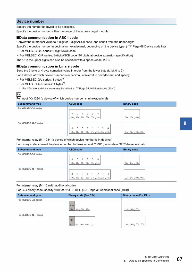
8 DEVICE ACCESS8.1 Data to be Specified in Commands 67
8
Device numberSpecify the number of device to be accessed.
Specify the device number within the range of the access target module.
■Data communication in ASCII codeConvert the numerical value to 6-digit or 8-digit ASCII code, and sent it from the upper digits.
Specify the device number in decimal or hexadecimal, depending on the device type. (Page 68 Device code list)
• For MELSEC-Q/L series: 6-digit ASCII code
• For MELSEC iQ-R series: 8-digit ASCII code (10 digits at device extension specification)
The '0' in the upper digits can also be specified with a space (code: 20H).
■Data communication in binary codeSend the 3-byte or 4-byte numerical value in order from the lower byte (L: bit 0 to 7).
For a device of which device number is in decimal, convert it to hexadecimal and specify.
• For MELSEC-Q/L series: 3 bytes*1
• For MELSEC iQ-R series: 4 bytes*1
*1 For C24, the additional code may be added. (Page 35 Additional code (10H))
Ex.
For input (X) 1234 (a device of which device number is in hexadecimal)
For internal relay (M) 1234 (a device of which device number is in decimal)
For binary code, convert the device number to hexadecimal. '1234' (decimal) '4D2' (hexadecimal)
For internal relay (M) 16 (with additional code)
For C24 binary code, specify '10H' as '10H + 10H'. (Page 35 Additional code (10H))
Subcommand type ASCII code Binary code
For MELSEC-Q/L series
For MELSEC iQ-R series
Subcommand type ASCII code Binary code
For MELSEC-Q/L series
For MELSEC iQ-R series
Subcommand type Binary code (For C24) Binary code (For E71)
For MELSEC-Q/L series
For MELSEC iQ-R series
030H
030H
131H
232H
333H
434H 34H 12H 00H
030H
030H
030H
030H
131H
232H
333H
434H 34H 12H 00H 00H
030H
030H
131H
232H
333H
434H D2H 04H 00H
030H
030H
030H
030H
131H
232H
333H
434H D2H 04H 00H 00H
10H 10H 00H 00H
DLE
10H 00H 00H
10H 10H 00H 00H 00H
DLE10H 00H 00H 00H

688 DEVICE ACCESS8.1 Data to be Specified in Commands
Device code listThe following shows the device code of each device and the notation of device number (decimal/hexadecimal).
The data to be set differs between MELSEC-Q/L series commands (subcommand: 0000, 0001) and MELSEC iQ-R series
subcommand (0002, 0003).
: Inaccessible
Device For MELSEC-Q/L series
For MELSEC iQ-R series
Device name Symbol Type Notation ASCII Binary ASCII Binary
Special relay SM Bit Decimal SM 91H SM** 0091H
Special register SD Word Decimal SD A9H SD** 00A9H
Input X Bit Hexadecimal X* 9CH X*** 009CH
Output Y Hexadecimal Y* 9DH Y*** 009DH
Internal relay M Decimal M* 90H M*** 0090H
Latch relay L Decimal L* 92H L*** 0092H
Annunciator F Decimal F* 93H F*** 0093H
Edge relay V Decimal V* 94H V*** 0094H
Link relay B Hexadecimal B* A0H B*** 00A0H
Data register D Word Decimal D* A8H D*** 00A8H
Link register W Hexadecimal W* B4H W*** 00B4H
Timer Contact TS Bit Decimal TS C1H TS** 00C1H
Coil TC C0H TC** 00C0H
Current value TN Word C2H TN** 00C2H
Long timer*1 Contact LTS Bit Decimal LTS* 0051H
Coil LTC LTC* 0050H
Current value LTN Double word LTN* 0052H
Retentive timer Contact STS Bit Decimal SS C7H STS* 00C7H
Coil STC SC C6H STC* 00C6H
Current value STN Word SN C8H STN* 00C8H
Long retentive
timer*1Contact LSTS Bit Decimal LSTS 0059H
Coil LSTC LSTC 0058H
Current value LSTN Double word LSTN 005AH
Counter Contact CS Bit Decimal CS C4H CS** 00C4H
Coil CC CC C3H CC** 00C3H
Current value CN Word CN C5H CN** 00C5H
Long counter*1 Contact LCS Bit Decimal LCS* 0055H
Coil LCC LCC* 0054H
Current value LCN Double word LCN* 0056H
Link special relay SB Bit Hexadecimal SB A1H SB** 00A1H
Link special register SW Word Hexadecimal SW B5H SW** 00B5H
Direct access input DX Bit Hexadecimal DX A2H DX** 00A2H
Direct access output DY Hexadecimal DY A3H DY** 00A3H
Index register Index register Z Word Decimal Z* CCH Z*** 00CCH
Long index register*2 LZ Double word LZ** 0062H
File register*3 Block switching
method
R Word Decimal R* AFH R*** 00AFH
Serial number access
method
ZR Hexadecimal ZR B0H ZR** 00B0H
Extended data register*4 D Word Decimal D* A8H
Extended link register*4 W Word Hexadecimal W* B4H
Refresh data register RD Word Decimal RD** 002CH
Network No. specified device
Link direct device
J\ Page 438 Accessing link direct devices

8 DEVICE ACCESS8.1 Data to be Specified in Commands 69
8
*1 Page 69 Considerations when accessing long timer, long retentive timer, or long counter*2 Page 69 Considerations when accessing long index register*3 Page 69 Consideration when accessing file register*4 Page 69 Consideration when accessing extended data register or extended link register
Considerations
■Devices that cannot be specified • Devices which are not listed on the list cannot be specified by the command for device access of MC protocol.
• The available device type and device range are in accordance with the device specifications of access target module.
Specify the device that can be used for the access target module.
• Accessing a local device is not available.
• When accessing a device that cannot be specified, create a program etc. to copy a value and store the value temporarily in
the device that can be specified and access it.
• When a device can be assigned to a standard global label in GX Works3, even the device, to which a device code cannot
be specified, can be accessed by specifying the label name. (Page 123 LABEL ACCESS)
■Considerations when accessing long timer, long retentive timer, or long counterUse any of the following commands.
*1 When reading data with a current value (LTN, LSTN) specified, the values of contacts and coils will be stored in the read data.
■Considerations when accessing long index registerUse a command to which double word access points can be specified.
• Page 97 Random read in word units (command: 0403)
• Page 104 Random write in word units (test) (command: 1402)
• Page 119 Register monitor data (command: 0801)
■Consideration when accessing file registerThe file register specified to "Use File Register of Each Program" in "CPU Parameter" or "PLC parameter" of the CPU module
cannot be accessed from external devices.
If the file register of the CPU module is consist of multiple blocks, use the device code of the serial number access method.
To specify the file register with the serial number access method, refer to the manual of CPU module.
■Consideration when accessing extended data register or extended link registerIf the access target CPU module does not support the access to the extended data register D65536 or later, and the extended
link register W10000 or later, replace the extended data register to the file register (ZR) and specify again. For the
replacement method, refer to the manual of Q/LCPU module.
I/O No. specified device U Page 440 Accessing module access devices
Page 442 Accessing CPU buffer memory access device
Module access device U\G Word Decimal G ABH G*** 00ABH
CPU buffer memory access device U3E\G Word Decimal G** 00ABH
U3E\HG Word Decimal HG** 002EH
Device Read Write
Long timer
Long retentive
timer
Contact LTS,
LSTS
Page 86 Batch read in word units (command: 0401)*1
Page 108 Random write in bit units (test) (command:
1402)
Coil LTC,
LSTC
Current
value
LTN,
LSTN
Page 86 Batch read in word units (command: 0401)
Page 97 Random read in word units (command: 0403)
Page 104 Random write in word units (test) (command:
1402)
Long counter Contact LCS Page 86 Batch read in word units (command: 0401)
Page 90 Batch read in bit units (command: 0401)
Page 92 Batch write in word units (command: 1401)
Page 95 Batch write in bit units (command: 1401)
Page 108 Random write in bit units (test) (command:
1402)
Coil LCC
Current
value
LCN Page 86 Batch read in word units (command: 0401)
Page 97 Random read in word units (command: 0403)
Page 92 Batch write in word units (command: 1401)
Page 104 Random write in word units (test) (command:
1402)
Device For MELSEC-Q/L series
For MELSEC iQ-R series
Device name Symbol Type Notation ASCII Binary ASCII Binary
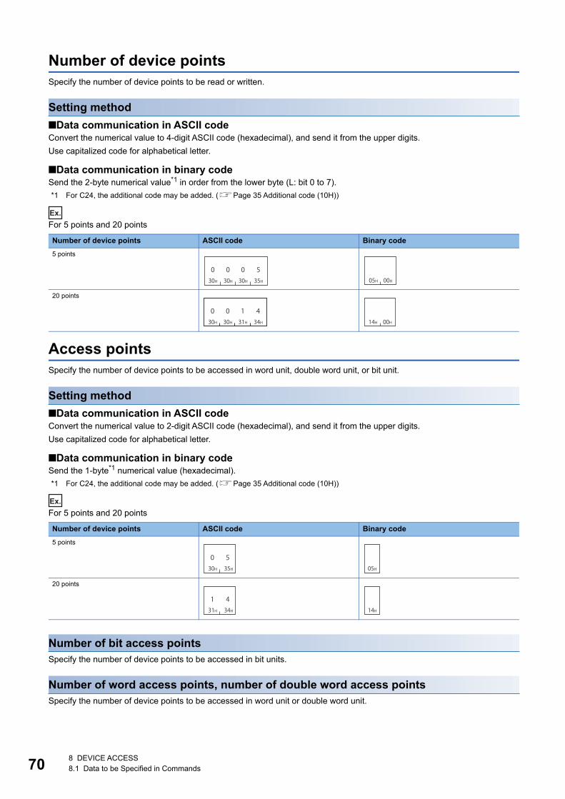
708 DEVICE ACCESS8.1 Data to be Specified in Commands
Number of device pointsSpecify the number of device points to be read or written.
Setting method
■Data communication in ASCII codeConvert the numerical value to 4-digit ASCII code (hexadecimal), and send it from the upper digits.
Use capitalized code for alphabetical letter.
■Data communication in binary codeSend the 2-byte numerical value*1 in order from the lower byte (L: bit 0 to 7).
*1 For C24, the additional code may be added. (Page 35 Additional code (10H))
Ex.
For 5 points and 20 points
Access pointsSpecify the number of device points to be accessed in word unit, double word unit, or bit unit.
Setting method
■Data communication in ASCII codeConvert the numerical value to 2-digit ASCII code (hexadecimal), and send it from the upper digits.
Use capitalized code for alphabetical letter.
■Data communication in binary codeSend the 1-byte*1 numerical value (hexadecimal).
*1 For C24, the additional code may be added. (Page 35 Additional code (10H))
Ex.
For 5 points and 20 points
Number of bit access pointsSpecify the number of device points to be accessed in bit units.
Number of word access points, number of double word access pointsSpecify the number of device points to be accessed in word unit or double word unit.
Number of device points ASCII code Binary code
5 points
20 points
Number of device points ASCII code Binary code
5 points
20 points
030H
030H
030H
535H 05H 00H
030H
030H
131H
434H 14H 00H
030H
535H 05H
131H
434H 14H

8 DEVICE ACCESS8.1 Data to be Specified in Commands 71
8
Number of blocksSpecify the number of blocks of the device to be accessed in hexadecimal.
Set each number of blocks within the following range.
• Number of word device blocks + Number of bit device blocks 120
In the following case, calculate it as access point 2.
• When accessing module of MELSEC iQ-R series by setting device extension specification (subcommand:
008)
Setting method
■Data communication in ASCII codeConvert the numerical value to 2-digit ASCII code (hexadecimal), and send it from the upper digits.
Use capitalized code for alphabetical letter.
■Data communication in binary codeSend the 1-byte*1 numerical value (hexadecimal).
*1 For C24, the additional code may be added. (Page 35 Additional code (10H))
Ex.
For 5 points and 20 points
Number of word device blocksSpecify the number of blocks of the word device.
Number of bit device blocksSpecify the number of blocks of the bit device.
Number of device points ASCII code Binary code
5 points
20 points
030H
535H 05H
131H
434H 14H

728 DEVICE ACCESS8.1 Data to be Specified in Commands
Read data, write dataThe read device value is stored for reading, and the data to be written is stored for writing.
The data order differs between bit units or word units.
For bit unitsThe following shows the data to be read and written in bit units.
■Data communication in ASCII codeThe ON/OFF status of each device are represented with single-digit ASCII code.
• For ON: '1' (31H)
• For OFF: '0' (30H)
■Data communication in binary codeRepresent the ON/OFF status of each device in 4-bit per 1 point.
• For ON: '1'
• For OFF: '0'
When the number of points is odd number, the lowest 4 bits are set to '0'.
Ex.
When indicating ON/OFF status of five points from M10
*1 For C24, the additional code may be added. (Page 35 Additional code (10H))
M10 M11 M12 M13 M14
ON OFF ON OFF ON
ASCII code Binary code (For C24)*1 Binary code (For E71)
131H
030H
131H
030H
131H 10H 10H 10H 10H 10H 10H
DLE DLE DLE10H 10H 10H

8 DEVICE ACCESS8.1 Data to be Specified in Commands 73
8
For word units (16-point unit for bit device)The following shows the data to be read and written in word units.
When handling data other than bit data, refer to the following section.
Page 77 Considerations for handling real number data and character string data
■Data communication in ASCII codeConvert the 1-word(16 points of bit device) numerical value to 4-digit ASCII code (hexadecimal), and send it from the upper
digits.
Use capitalized code for alphabetical letter.
The ON/OFF status of bit device is a value of hexadecimal 1-digit in 4-point units.
Ex.
When indicating ON/OFF status of 32 points from M16
Ex.
When indicating the stored data of D350 and D351
1 6 A B 1 2 3 4 C D0 0 0 2
b15
1 0 1 0 1 0 1 1 0 0 0 1 0 0 1 0 0 0 1 1
b14 b13 b12 b11b10 b9 b8 b7 b6 b5 b4 b3 b2 b1 b0
0 1 0 0 1 1 0 0 1 1 0 1
b15b14 b13 b12 b11b10 b9 b8 b7 b6 b5 b4 b3 b2 b1 b0
M 0 0 0 0
44H43H34H33H32H31H42H41H32H30H30H30H36H31H30H30H30H30H2AH4DH
M16M31
0 OFF1 ON
A B 1 2 3 4 C
M32M47
D
The device point value becomes "0002" in 16-points units.Device code
Number of device pointsHead device Data
toto
Data
*
0 0 3 5 0 5 6 A B 1 7 0 F0 0 0 2D 0*
44H 2AH 30H 30H 30H 33H 35H 30H 30H 30H 32H 35H 36H 41H 42H 31H 37H 30H 46H30H
Device code
Number of device pointsHead device Data Data
The content of D350 indicates 56ABH (22187 in decimal)
The content of D351 indicates 170FH (5903 in decimal)

748 DEVICE ACCESS8.1 Data to be Specified in Commands
■Data communication in binary codeSend the numerical value in order from the lower byte (L: bit 0 to 7) by handling 16 points unit as 2 bytes.
Ex.
When indicating ON/OFF status of 32 points from M16
Ex.
When indicating the stored data of D350 and D351
10H 00H 00H 90H 02H 00H 12H ABH CDH 34H
0 0 0 1 0 0 1 0 1 0 1 0 1 0 1 1 1 1 0 0
b11b10 b9 b8b7 b6 b5 b4 b3 b2 b1 b0
1 1 0 1 0 0 1 1 0 1 0 0
b15b14 b13b12 b11b10 b9 b8b7 b6 b5 b4 b3 b2 b1 b0b15b14 b13b12
M16M23 M24M31 M32M39 M40M47
1 2 A B C D 3 4
0 OFF1 ON
The device point value becomes "02" in 16-points units.
Head device
Device code
Number of device points Data
to to toto
Data
A B 5 6 0 F 1 7
5 6 A B 1 7 0 F
5EH 01H 00H A8H 02H 00H ABH 56H 0FH 17H
Head device
Device code
Number of device points Data Data
The stored value of the request data or the response data.
The value to read or write.
The content of D350 indicates 56ABH(22187 in decimal)
The content of D351 indicates 170FH(5903 in decimal)

8 DEVICE ACCESS8.1 Data to be Specified in Commands 75
8
For double word unit (32-point unit for bit device)The following shows the data to be read and written in double word units.
■Data communication in ASCII codeConvert the 2-word numerical value (32 points of bit device) to 8-digit ASCII code (hexadecimal), and send it from the upper
digits.
Use capitalized code for alphabetical letter.
The ON/OFF status of the bit device is 1-digit hexadecimal value in 4-point units.
Ex.
When indicating ON/OFF status of 32 points from M16
Ex.
When indicating the stored data of D350 (D351)
M32M47
1 6 A B 1 2 3 4 C D
b15
1 0 1 0 1 0 1 1 0 0 0 1 0 0 1 0 0 0 1 1
b14b13b12 b11b10 b9 b8 b7 b6 b5 b4 b3 b2 b1 b0
0 1 0 0 1 1 0 0 1 1 0 1
b15b14b13b12 b11b10 b9 b8 b7 b6 b5 b4 b3 b2 b1 b0
A B 1 2 3 4 C D
M 0 0 0 0
M16M31
44H43H34H33H32H31H42H41H36H31H30H30H30H30H2AH4DH
0 OFF1 ON
Device code Device number Data
toto
*
0 0 3 5 0 5 6 A B1 7 0 FD 0
44H 2AH 30H 30H 30H 33H 35H 35H 36H 41H 42H31H 37H 30H 46H30H
*
Device code Device number Data
The content of D351 indicates 170FH (5903 in decimal)
The content of D350 indicates 56ABH (22187 in decimal)

768 DEVICE ACCESS8.1 Data to be Specified in Commands
■Data communication in binary codeSend the numerical value in order from the lower byte (L: bit 0 to 7) by handling 32 points unit as 4 bytes.
Ex.
When indicating ON/OFF status of 32 points from M16
Ex.
When indicating the stored data of D350 (D351)
0 0 0 1 0 0 1 0 1 0 1 0 1 0 1 11 1 0 0
b11 b10 b9 b8b7 b6 b5 b4 b3 b2 b1 b0
1 1 0 1 0 0 1 1 0 1 0 0
b15 b14 b13 b12 b11 b10 b9 b8b7 b6 b5 b4 b3 b2 b1 b0
1 2 A BC D 3 4b15 b14 b13 b12
M16M23 M24M31 M32M39 M40M47
10H 00H 00H 90H 12H ABHCDH 34H
0 OFF1 ON
Number of device points
Device code Data
totototo
A B 5 6 0 F 1 7
5 6 A B 1 7 0 F
5EH 01H 00H A8H ABH 56H 0FH 17H
Number of device points
Device code Data
The stored value of the request data or the response data.
The value to read or write.
The content of D350 indicates 56ABH(22187 in decimal)
The content of D351 indicates 170FH(5903 in decimal)

8 DEVICE ACCESS8.1 Data to be Specified in Commands 77
8
Considerations for handling real number data and character string dataThe word data and double word data are handled as integer value (16-bit data or 32-bit data).
When data other than integer (real number, character string) is stored in a device, the stored value is read as integer value.
• When real number (0.75) is stored in D0 and D1: D0 = 0000H, D1 = 3F40H
• When character string ('12AB') is stored in D2 and D3: D2 = 3231H, D3 = 4241H
For data to be used as real number or character string data in the instructions of the programmable controller, write it to the
device/label according to the defined data specification method. For more details on how to specify data used in instructions,
refer to the programming manual of the CPU module used.
■For character string data The following shows the images how character string data is stored.
Ex.
Write ASCII code character string data used in the instructions which handle character strings to word device
Store the character string ('ABCD') to D0 and D1: D0 = 4241H ('BA'), D1 = 4443H ('DC')
Specify the following data for write data.
When communicating ASCII code character string data in ASCII code, data is rearranged every two
characters and stored.
Item For ASCII code character string For Unicode character string
Character string to be stored 'ABC' 'ABCD' 'ABCD'
Character code '41H', '42H', '43H' '41H', '42H', '43H', '44H' '0041H', '0042H', '0043H', '0044H'
Image when character string data is stored from
D0
NULL indicates 00H. NULL indicates 00H. NULL indicates 0000H.
ASCII code Binary code
AB
CNULL
D0
D1
AB
CD
NULL NULL
D0
D1
D2
A
B
C
D
NULL
D0
D1
D2
D4
D3
4 2 434H 32H 34H
132H 34H 34H
4 3434H 33H 30H
430H 30H 30H
0 0 0 0
AB CD NULL NULL
D0 D1 D2
A B C41H 42H 43H
D44H
NULL
00H 00HNULL
D0 D2D1

788 DEVICE ACCESS8.1 Data to be Specified in Commands
Set/resetSpecify the ON/OFF status of bit device.
• For ON: '1'
• For OFF: '0'
Subcommand type ASCII code Binary code
For MELSEC-Q/L series
For MELSEC iQ-R series
Subcommand type ASCII code Binary code
For MELSEC-Q/L series
For MELSEC iQ-R series
030H
131H 01H
030H
030H
030H
131H 01H 00H
030H
030H 00H
030H
030H
030H
030H 00H 00H

8 DEVICE ACCESS8.1 Data to be Specified in Commands 79
8
Monitor condition specificationThe following explains the data to be used when specifying monitor conditions by the following commands.
• Random read in word units (command: 0403)
• Register monitor data (command: 0801)
The monitor conditions can be specified by following QCPUs.
• Basic model QCPU
• High Performance model QCPU
• Process CPU
To access a module which does not support this function, select the subcommand that does not specify
monitor conditions. For more information on the supported modules, refer to the following section.
Page 469 Accessible Modules for Each Command
When the subcommands which do not specify monitor conditions are selected, each data for specifying the
monitor conditions are not necessary.
Item Description Reference
Step No.
specification
File
specification
File No. Specify the registration number of file which
includes a program to be the conditions in a module.
The number for specification can be obtained from
the file control command.
Page 82 Step No. specification
Page 296 File No.
Page 297 File name, extension, and
attribute
File name Specify the file name, extension, attribute of a file
which include a program to be the conditions.Extension
Attribute
SFC
specification
SFC pattern Specify this when a program is SFC. Page 84 SFC specification
SFC block I/O
No.
Specify the SFC block No. and SFC step No. which
include a step to be the conditions.
SFC step No.
Step No. Specify the step No., pointer (P) No., or interrupt
pointer (I) No. for a program to be the condition.
Page 84 Step No.
Device
specification
Word device
value
specification
Device Specify the device to be a condition. Page 85 Mask value, monitor conditions
when word device value is specifiedMask value Specify this when detecting arbitrary bit range of
word device.
Monitor
condition value
Specify the device value to be a condition.
Bit device value
specification
Device Specify the device to be a condition. Page 85 Monitor conditions when bit device
value is specifiedMonitor
condition value
Specify the device value to be a condition.
Monitor condition Step No. specification
Device specification
Monitor condition specification

808 DEVICE ACCESS8.1 Data to be Specified in Commands
Specification of read timing by monitor conditionThe read timing can be changed by specifying monitor conditions according to the selection of subcommand.
■When do not specify monitor conditionData is read by the END processing after a read request.
■When monitor condition is specifiedData is read by the END processing after the specified monitor conditions are satisfied.
Monitoring with multiple conditions to the device memory of the same CPU module cannot be performed at
the same time. When this command, to which a monitor condition is specified, is executed while monitor with
other conditions is being performed, the command is completed abnormally.
Timer 0 monitoring time Timer 1 monitoring time Timer 2 monitoring time
Command messageExternal device side
Module side Response message
DataRead request
Program
END processingSequence scan
Timer 0 monitoring time Timer 1 monitoring time Timer 2 monitoring time
Command messageExternal device sideModule side Response message
DataRead request
Program
END processing Timing when the condition is metSequence scan

8 DEVICE ACCESS8.1 Data to be Specified in Commands 81
8
Monitor conditionFollowing conditions can be specified as "Monitor condition" for read timing.
When the step No. specification and device specification are specified together, the read processing is performed when both
of the conditions are satisfied.
Specify the following values according to the conditions.
: Specified, : Not specified
Conditions that can be specified Condition satisfaction timing
Step No. specification When specified program step is executed
Device specification Word device value specification When specified word device value reached the specified value
Bit device value specification When specified bit device turned ON/OFF
Step No. specification
Device specification ASCII code Binary code
Word device value
specification
Bit device value
specification
030H
131H
030H
F46H 01H 0FH
030H
232H
030H
F46H 02H 0FH
030H
333H
030H
F46H 03H 0FH
030H
434H
030H
F46H 04H 0FH
030H
535H
030H
F46H 05H 0FH

828 DEVICE ACCESS8.1 Data to be Specified in Commands
Step No. specificationSpecify a condition using a step No. of program.
Data is read at the END processing immediately after a step of the specified program is executed.
■When step No. is specifiedSpecify the following items.
*1 When 'FFFFH' is specified to the file , the specified file is searched with the file name and extension. In this case, a read and write request from a supported device to the CPU module may be delayed more than one sequence scan time.
■When step No. is not specifiedSet the following when a monitor condition without step No. specification is selected.
• File No.: 0
• File name, extension, attribute: Space (20H)
• SFC specification, step No.: 0
Item Description Reference
Step No.
specification
File
specification
File No. Specify the registration number of file which
includes a program to be the conditions in a module.
The number for specification can be obtained from
the file control command.*1
Page 296 File No.
File name Specify the file name, extension, attribute of a file
which includes a program to be the conditions.
Page 297 File name, extension, and
attributeExtension
Attribute
SFC
specification
SFC pattern Specify this when a program is SFC. Page 84 SFC specification
SFC block I/O
No.
Specify the SFC block No. and SFC step No. which
include a step to be the conditions.
SFC step No.
Step No. Specify the step No., pointer (P) No., or interrupt
pointer (I) No. for a program to be the condition.
Page 84 Step No.
ASCII code
Binary code
0 0 0 030H 30H30H 30H
0 0 0 030H 30H30H 30H
0 0 0 030H 30H30H 30H
0 0 0 030H30H
0 030H 30H 20H 20H20H 20H30H 30H 20H 20H 20H20H20H20H20H20H
SFC pattern Step No.Block No. Step No.Extension AttributeFile nameFile No.
(8 digits)File specification SFC specification
00H 00H 20H 20H 20H 00H 00H00H00H20H 20H20H 00H 00H 00H 00H 00H 00H20H20H20H20H20H20H
SFC pattern
File No.
StepNo.
Block No.
Extension Attribute Step No.File name
SFC specificationFile specification

8 DEVICE ACCESS8.1 Data to be Specified in Commands 83
8
Device specificationSpecify a condition using a device and its value.
Data is read at the END processing immediately after the specified device reached the specified value.
■When word device value is specifiedSet the following when a monitor condition which specifies word device value is selected.
■When bit device value is specifiedSet the following when a monitor condition which specifies bit device value is selected.
Item Description Reference
Device
specification
Word device
value
specification
Device Specify the device to be a condition. Page 65 Devices
Mask value Specify this when detecting arbitrary bit range of
word device.
Page 85 Mask value, monitor conditions when
word device value is specified
Monitor
condition value
Specify the device value to be a condition.
Bit device value
specification
Device Specify an arbitrary device.
Monitor
condition value
Specify the fixed value (0).
ASCII code
Binary code
Item Description Reference
Device
specification
Word device
value
specification
Device Specify an arbitrary device.
Mask value Specify the fixed value (0).
Monitor
condition value
Bit device value
specification
Device Specify the device to be a condition. Page 65 Devices
Monitor
condition value
Specify the condition with the following value.
02H: Condition is satisfied at rising (OFFON)
04H: Condition is satisfied at falling (ONOFF)
Page 85 Monitor conditions when bit device
value is specified
ASCII code
Binary code
Device Monitor condition valueMask value Device specification Monitor condition value
Device code Device number
Word device value specification Bit device value specification ( Fixed value for dummy )
30H 30H4DH 2AH
M * 0 030H 30H30H 30H
0 0 0 030H 30H
0 0
Monitor condition value
Monitor condition value Device specificationDevice Mask value
Device number Device code
Word device value specification Bit device value specification ( Fixed value for dummy )
00H 00H 00H 00H90H
Monitor condition valueDeviceMonitor condition valueMask valueDevice
Device code
Device number
Bit device value specificationWord device value specification ( Fixed value for dummy )
30H 30H30H 30H
0 0 0 030H 30H44H 2AH
D * 0 030H 30H30H 30H
0 0 0 0 0 030H 30H30H 30H0 0
Monitor condition value
Monitor condition value DeviceDevice Mask value
Device code
Device number
Word device value specification ( Fixed value for dummy ) Bit device value specification
00H 00H 00H 00HA8H 00H00H 00H

848 DEVICE ACCESS8.1 Data to be Specified in Commands
■When no device is specifiedSet the following when monitor condition without device specification is selected.
SFC specificationThe block No. and step No. of SFC (MELSAP3) program can be specified as a monitor condition.
Specify the following values.
■Data communication in ASCII codeConvert the numerical value to 4-digit ASCII code (hexadecimal), and send it from the upper digits.
■Data communication in binary codeSend the 2-byte numerical value*1 in order from the lower byte (L: bit 0 to 7).
*1 For C24, the additional code may be added. (Page 35 Additional code (10H))
Ex.
For 0003H
Step No.Specify the step No., pointer (P) No., or interrupt pointer (I) No. of the sequence program.
Specify a following 4-byte value.
■Data communication in ASCII codeConvert the numerical value to 8-digit ASCII code (hexadecimal), and send it from the upper digits.
■Data communication in binary codeSend the 4-byte numerical value*1 in order from the lower byte (L: bit 0 to 7).
*1 For C24, the additional code may be added. (Page 35 Additional code (10H))
Ex.
When specifying the interrupt pointer I28 (8000001CH)
ASCII code
Binary code
Condition SFC pattern SFC block No. SFC step No.
Specify an SFC program. 0003H 0000H to 013FH (0 to 319) 0000H to 01FFH (0 to 511)
Do not specify SFC program 0000H 0000H 0000H
ASCII code Binary code
Condition b31 b30 b29 to b0
Specify the step No. of a sequence program 0 0 (Step No. of the arbitrary sequence program)
Specify pointer No. 0 1 (Arbitrary pointer No.)
Specify an interrupt pointer No. 1 0 (Arbitrary interrupt pointer No.)
Do not specify 00000000H
ASCII code Binary code
30H 30H4DH 2AH
M * 0 030H 30H30H 30H
0 0 0 030H 30H
0 030H 30H30H 30H
0 0 0 030H 30H44H 2AH
D * 0 030H 30H30H 30H
0 0 0 0 0 030H 30H30H 30H
0 0
00H 00H 00H 00H90H00H 00H 00H 00HA8H 00H00H 00H
030H
030H
030H
333H 03H 00H
8 0 038H 30H 30H
030H
0 0 130H 30H 31H
C 43H 1CH 00H 00H 80H

8 DEVICE ACCESS8.1 Data to be Specified in Commands 85
8
Mask value, monitor conditions when word device value is specifiedSpecify the value of word device to be set as a monitor condition.
Arbitrary bit range of word devices can only be specified by specifying mask value.
(Logical AND by each bit of the specified word device data and the designated mask value is compared with the monitor
condition value.)
■Data communication in ASCII codeConvert the numerical value to 4-digit ASCII code (hexadecimal), and send it from the upper digits.
■Data communication in binary codeSend the 2-byte numerical value*1 in order from the lower byte (L: bit 0 to 7).
*1 For C24, the additional code may be added. (Page 35 Additional code (10H))
Ex.
Specifying when bit 0 to 14 of D0 reaches 1000 (3E8H) as a condition
• Mask value: 7FFFH
• Monitor condition value: 03E8H
Monitor conditions when bit device value is specifiedSpecify a bit device status change as the monitor condition from either rising (OFF ON) or falling (ON OFF).
ASCII code Binary code
ASCII code Binary code
Condition ASCII code Binary code
Rising (OFFON)
Falling (ONOFF)
737H
F46H 46H
F46H
FFFH 7FH
030H
333H 45H
838H
EE8H 03H
030H
232H 02H
030H
434H 04H

868 DEVICE ACCESS8.2 Batch Read and Write
8.2 Batch Read and WriteRead or write the values of consecutive devices in batch by specifying the number of device points.
Batch read in word units (command: 0401)Read values from devices in word units.
When accessing any of the following devices, use the device extension specification (subcommand: 008).
• Link direct device
• Module access device
• CPU buffer memory access device
For the message format for device extension specification, refer to the following section.
Page 436 Read/Write by Device Extension Specification
Message formatThe following shows the message format of the request data and response data of the command.
■Request data
■Response dataThe value of read device is stored in word units. The data order differs between ASCII code or binary code. (Page 72
Read data, write data)
Data specified by request data
■Command
■Subcommand
For 2C frame, the specification is not required. Functions and specification methods are equivalent to the subcommands for
MELSEC-Q/L series.
Frame ASCII code Binary code
4C/3C/4E/3E frame
2C frame
Type ASCII code Binary code
For MELSEC-Q/L series
For MELSEC iQ-R series
Subcommand Head deviceCommand Number of device points
030H
434H
030H
131H 01H 04H
232H
030H
030H
030H
030H 00H 00H
030H
030H
030H
232H 02H 00H

8 DEVICE ACCESS8.2 Batch Read and Write 87
8
■Head deviceSpecify the head device of the consecutive devices. (Page 65 Devices)
The following devices cannot be specified.
• Long timer (contact: LTS, coil: LTC)
• Long retentive timer (contact: LSTS, coil: LSTC)
• Long index register (LZ)
Page 69 Considerations when accessing long timer, long retentive timer, or long counter
Page 69 Considerations when accessing long index register
■Number of device pointsSpecify the number of device points to be read within the following range in word units. (Page 70 Number of device
points)
Read 16-point bit device by specifying one point of "Number of device points".
Set the head device number for MELSEC-A series module with a multiple of 16.
■Considerations for reading a long timer or long retentive timer deviceWhen reading data with a current value (LTN, LSTN) specified as the head device, the values of contacts and coils will be
stored in the response data.
The configuration of the response data is as follows:
Specify four words per one device as the number of device points in the request data.
Ex.
When reading the two points of the long timer (LT0 and LT1), specify LTN0 as the head device and eight words as the number
of device points.
Access target Range
Word device Bit device Double word device
MELSEC iQ-R series module
MELSEC-Q/L series module
1 to 960 points 1 to 960 words
(1 to 15360 points)
1 to 960 words
(LCN: 1 to 480 points)
(LTN, LSTN: 1 to 240
points)
MELSEC-QnA series module
Module on other station via MELSEC-QnA series network module
1 to 480 points 1 to 480 words
(1 to 7680 points)
MELSEC-A series module 1 to 64 points 1 to 32 words
(1 to 512 points)
Data Description
1st word The current value is stored.
2nd word
3rd word b0: The value of the coil is stored.
b1: The value of the contact is stored.
b2 to b15: Used by the system
4th word Used by the system
01234567
LTN0
LTS1 LTC1
LTN1
LT0
LT1
b1 b0
b1 b0
LTS0 LTC0

888 DEVICE ACCESS8.2 Batch Read and Write
Communication example (Reading bit device)Read the value of M100 to M131 (for 2 words). (Subcommand: for MELSEC-Q/L series)
■Data communication in ASCII code(Request data)
(Response data)
■Data communication in binary code(Request data)
(Response data)
0 4 0 130H 34H 30H 31H
0 0 030H 30H 30H
0 M *30H 4DH 2AH
0 0 030H 30H 30H
1 0 031H 30H 30H
0 0 030H 30H 30H
232H
Device codeSubcommand Head device number Number of device points
1
M115
1 2 3 4 0 0 0 20 0 0 1 0 0 1 0 0 0 1 1 0 1 0 0 0 0 0 0 0 0 0 0 0 0 0 0 0 0 1 0
2 3 431H 32H 33H 34H
0 0 030H 30H 30H
232H
M100 M131 M116
0 = OFF1 = ON
to to
01H 04H 00H 00H 64H 00H 00H 90H 02H 00H
Device codeSubcommand
Number of device points
Head device number
M107
3 4 1 2 0 2 0 00 0 1 1 0 1 0 0 0 0 0 1 0 0 1 0 0 0 0 0 0 0 1 0 0 0 0 0 0 0 0 0
34H 12H 02H 00H
M100 M115 M108 M123 M116 M131 M124
0 = OFF1 = ON
to to to to

8 DEVICE ACCESS8.2 Batch Read and Write 89
8
Communication example (Reading word device)Read values of T100 to T102. (Subcommand: for MELSEC-Q/L series)
T100 = 4660 (1234H), T101 = 2 (2H), T102 = 7663 (1DEFH) are stored.
■Data communication in ASCII code(Request data)
(Response data)
■Data communication in binary code(Request data)
(Response data)
0 4 0 130H 34H 30H 31H
0 0 030H 30H 30H
0 T N30H 54H 4EH
0 0 030H 30H 30H
1 0 031H 30H 30H
0 0 030H 30H 30H
333H
Device codeSubcommand Head device number Number of device points
1 2 3
T100 T101 T102
431H 32H 33H 34H
0 0 030H 30H 30H
232H
1 D E31H 44H 45H
F46H
01H 04H 00H 00H 64H 00H 00H C2H 03H 00H
Device codeSubcommand
Number of device points
Head device number
34H 12H 02H 00H EFH 1DH
T100 T101 T102
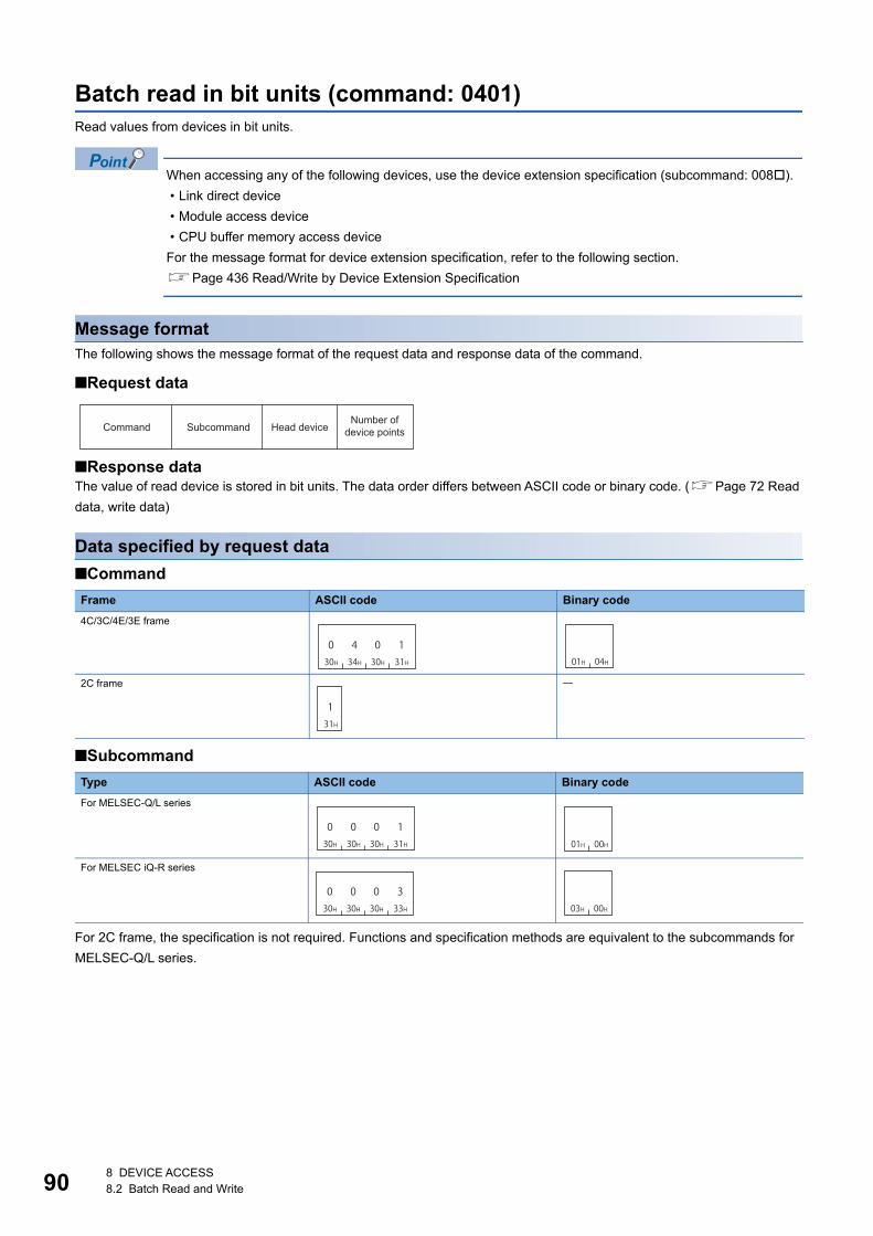
908 DEVICE ACCESS8.2 Batch Read and Write
Batch read in bit units (command: 0401)Read values from devices in bit units.
When accessing any of the following devices, use the device extension specification (subcommand: 008).
• Link direct device
• Module access device
• CPU buffer memory access device
For the message format for device extension specification, refer to the following section.
Page 436 Read/Write by Device Extension Specification
Message formatThe following shows the message format of the request data and response data of the command.
■Request data
■Response dataThe value of read device is stored in bit units. The data order differs between ASCII code or binary code. (Page 72 Read
data, write data)
Data specified by request data
■Command
■Subcommand
For 2C frame, the specification is not required. Functions and specification methods are equivalent to the subcommands for
MELSEC-Q/L series.
Frame ASCII code Binary code
4C/3C/4E/3E frame
2C frame
Type ASCII code Binary code
For MELSEC-Q/L series
For MELSEC iQ-R series
Command Subcommand Head deviceNumber of
device points
030H
434H
030H
131H 01H 04H
131H
030H
030H
030H
131H 01H 00H
030H
030H
030H
333H 03H 00H

8 DEVICE ACCESS8.2 Batch Read and Write 91
8
■Head deviceSpecify the head device of the consecutive devices. (Page 65 Devices)
The following devices cannot be specified.
• Long timer (contact: LTS, coil: LTC)
• Long retentive timer (contact: LSTS, coil: LSTC)
• Long index register (LZ)
Page 69 Considerations when accessing long timer, long retentive timer, or long counter
Page 69 Considerations when accessing long index register
■Number of device pointsSpecify the number of device points to be read within the following range. (Page 70 Number of device points)
Communication exampleRead values of M100 to M107. (Subcommand: for MELSEC-Q/L series)
■Data communication in ASCII code(Request data)
(Response data)
■Data communication in binary code(Request data)
(Response data)
Access target C24 E71
ASCII code Binary code
MELSEC iQ-R series module
MELSEC-Q/L series module
1 to 7904 points 1 to 3584 points 1 to 7168 points
MELSEC-QnA series module
Module on other station via MELSEC-QnA series network module
1 to 3952 points 1 to 1792 points 1 to 3584 points
MELSEC-A series module 1 to 256 points
0 4 0 130H 34H 30H 31H
0 0 030H 30H 30H
1 M *31H 4DH 2AH
0 0 030H 30H 30H
1 0 031H 30H 30H
0 0 030H 30H 30H
838H
Device codeSubcommand Head device number Number of device points
0
M100 M107
0 0 130H 30H 30H 31H
0 0 130H 30H 31H
131H
0 = OFF1 = ON
to
01H 04H 01H 00H 64H 00H 00H 90H 08H 00H
Device codeSubcommand
Number of device points
Head device number
M100M101
00H 01H 00H 11H
M106M107
0 = OFF1 = ON
to

928 DEVICE ACCESS8.2 Batch Read and Write
Batch write in word units (command: 1401)Write values to devices in word units.
When accessing any of the following devices, use the device extension specification (subcommand: 008).
• Link direct device
• Module access device
• CPU buffer memory access device
For the message format for device extension specification, refer to the following section.
Page 436 Read/Write by Device Extension Specification
Message formatThe following shows the message format of the request data and response data of the command.
■Request data
■Response dataThere is no response data for this command.
Data specified by request data
■Command
■Subcommand
For 2C frame, the specification is not required. Functions and specification methods are equivalent to the subcommands for
MELSEC-Q/L series.
Frame ASCII code Binary code
4C/3C/4E/3E frame
2C frame
Type ASCII code Binary code
For MELSEC-Q/L series
For MELSEC iQ-R series
Command Subcommand Head deviceNumber of
device points Write data
131H
434H
030H
131H 01H 14H
434H
030H
030H
030H
030H 00H 00H
030H
030H
030H
232H 02H 00H
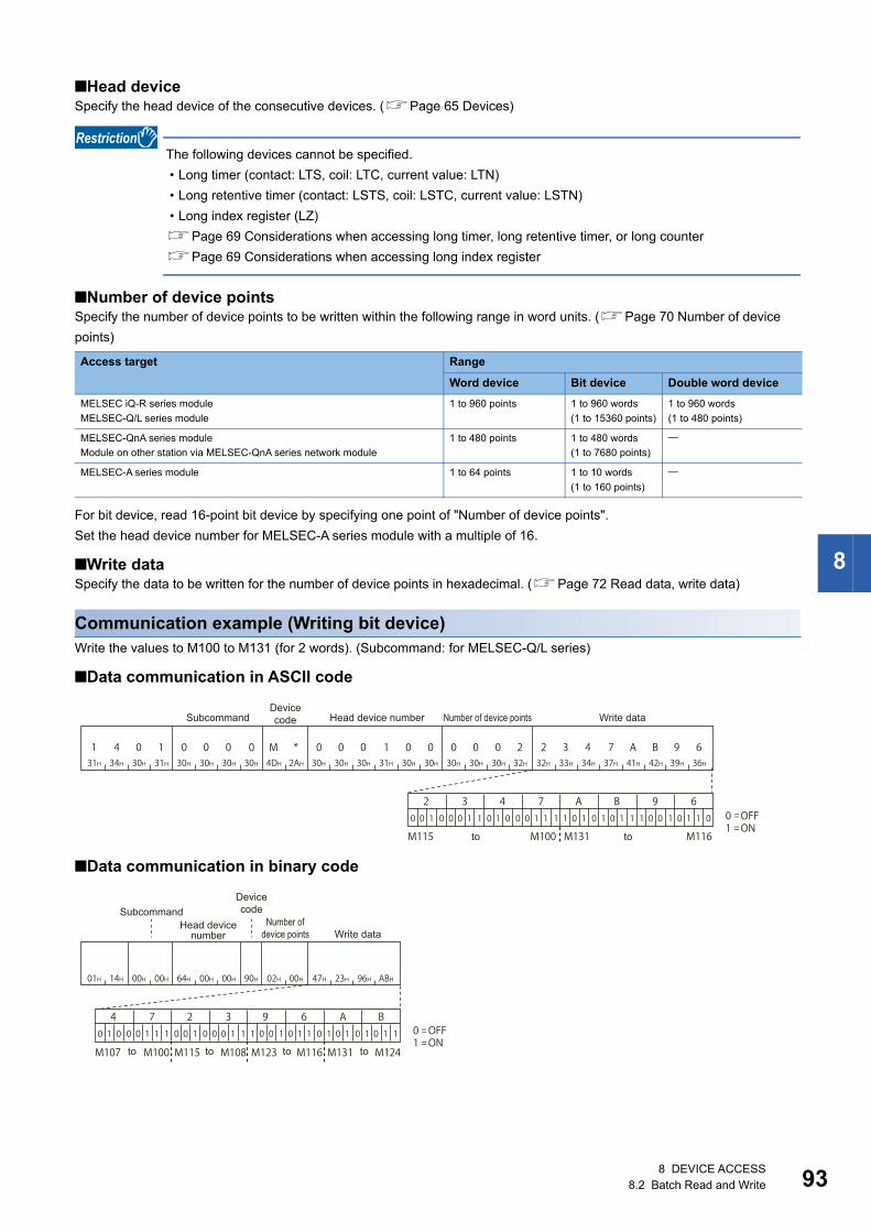
8 DEVICE ACCESS8.2 Batch Read and Write 93
8
■Head deviceSpecify the head device of the consecutive devices. (Page 65 Devices)
The following devices cannot be specified.
• Long timer (contact: LTS, coil: LTC, current value: LTN)
• Long retentive timer (contact: LSTS, coil: LSTC, current value: LSTN)
• Long index register (LZ)
Page 69 Considerations when accessing long timer, long retentive timer, or long counter
Page 69 Considerations when accessing long index register
■Number of device pointsSpecify the number of device points to be written within the following range in word units. (Page 70 Number of device
points)
For bit device, read 16-point bit device by specifying one point of "Number of device points".
Set the head device number for MELSEC-A series module with a multiple of 16.
■Write dataSpecify the data to be written for the number of device points in hexadecimal. (Page 72 Read data, write data)
Communication example (Writing bit device)Write the values to M100 to M131 (for 2 words). (Subcommand: for MELSEC-Q/L series)
■Data communication in ASCII code
■Data communication in binary code
Access target Range
Word device Bit device Double word device
MELSEC iQ-R series module
MELSEC-Q/L series module
1 to 960 points 1 to 960 words
(1 to 15360 points)
1 to 960 words
(1 to 480 points)
MELSEC-QnA series module
Module on other station via MELSEC-QnA series network module
1 to 480 points 1 to 480 words
(1 to 7680 points)
MELSEC-A series module 1 to 64 points 1 to 10 words
(1 to 160 points)
1 4 0 131H 34H 30H 31H
0 0 030H 30H 30H
0 M *30H 4DH 2AH
0 0 030H 30H 30H
1 0 031H 30H 30H
2 3 432H 33H 34H
7 A B37H 41H 42H
9 639H 36H
0 0 030H 30H 30H
232H
M115
2 3 4 7 A B 9 60 0 1 0 0 0 1 1 0 1 0 0 0 1 1 1 1 0 1 0 1 0 1 1 1 0 0 1 0 1 1 0
M100 M131 M116
0 OFF1 ON
Device codeSubcommand Head device number Number of device points Write data
toto
01H 14H 00H 00H 64H 00H 00H 47H 23H 96H ABH90H 02H 00H
M107
4 7 2 3 9 6 A B0 1 0 0 0 1 1 1 0 0 1 0 0 0 1 1 1 0 0 1 0 1 1 0 1 0 1 0 1 0 1 1
M100 M115 M108 M123 M116 M131 M124
0 OFF1 ON
Device codeSubcommand
to to to to
Number of device points
Head device number Write data

948 DEVICE ACCESS8.2 Batch Read and Write
Communication example (Writing word device)Write '6549' (1995H) to D100, '4610' (1202H) to D101, and '4400' (1130H) to D102. (Subcommand: for MELSEC-Q/L series)
■Data communication in ASCII code
■Data communication in binary code
1 4 0 131H 34H 30H 31H
0 0 030H 30H 30H
0 D *30H 44H 2AH
0 0 030H 30H 30H
1 0 031H 30H 30H
1 9 931H 39H 39H
5 1 235H 31H 32H
0 230H 32H
1 131H 31H
3 033H 30H
0 0 030H 30H 30H
333H
D100 D101 D102
Device codeSubcommand Head device number Number of device points Write data
01H 14H 00H 00H 64H 00H 00H 95H 19H 02H 12H 30H 11HA8H 03H 00H
D100 D101 D102
Device codeSubcommand
Number of device points
Head device number Write data

8 DEVICE ACCESS8.2 Batch Read and Write 95
8
Batch write in bit units (command: 1401)Write values to devices in bit units.
When accessing any of the following devices, use the device extension specification (subcommand: 008).
• Link direct device
• Module access device
• CPU buffer memory access device
For the message format for device extension specification, refer to the following section.
Page 436 Read/Write by Device Extension Specification
Message formatThe following shows the message format of the request data and response data of the command.
■Request data
■Response dataThere is no response data for this command.
Data specified by request data
■Command
■Subcommand
For 2C frame, the specification is not required. Functions and specification methods are equivalent to the subcommands for
MELSEC-Q/L series.
Frame ASCII code Binary code
4C/3C/4E/3E frame
2C frame
Type ASCII code Binary code
For MELSEC-Q/L series
For MELSEC iQ-R series
Command Subcommand Head device Number of device points Write data
131H
434H
030H
131H 01H 14H
333H
030H
030H
030H
131H 01H 00H
030H
030H
030H
333H 03H 00H

968 DEVICE ACCESS8.2 Batch Read and Write
■Head deviceSpecify the head device of the consecutive devices. (Page 65 Devices)
The following devices cannot be specified.
• Long timer (contact: LTS, coil: LTC, current value: LTN)
• Long retentive timer (contact: LSTS, coil: LSTC, current value: LSTN)
• Long counter (current value: LCN)
• Long index register (LZ)
Page 69 Considerations when accessing long timer, long retentive timer, or long counter
Page 69 Considerations when accessing long index register
■Number of device pointsSpecify the number of device points to be written within the following range. (Page 70 Number of device points)
■Write dataSpecify the value to be written to a device for the number equivalent to the specified number of device points. (Page 72
Read data, write data)
Communication exampleWrite values to M100 to M107. (Subcommand: for MELSEC-Q/L series)
■Data communication in ASCII code
■Data communication in binary code
Access target C24 E71
ASCII code Binary code
MELSEC iQ-R series module
MELSEC-Q/L series module
1 to 7904 points 1 to 3584 points 1 to 7168 points
MELSEC-QnA series module
Module on other station via MELSEC-QnA series network module
1 to 3952 points 1 to 1792 points 1 to 3584 points
MELSEC-A series module 1 to 160 points
1 4 0 131H 34H 30H 31H
0 0 030H 30H 30H
1 M *31H 4DH 2AH
0 0 030H 30H 30H
1 0 031H 30H 30H
1 1 031H 31H 30H
0 1 130H 31H 31H
0 030H 30H
0 0 030H 30H 30H
838H
M100 M107 0 OFF1 ON
Device codeSubcommand Head device number Number of device points Write data
to
01H 14H 01H 00H 64H 00H 00H 11H 00H 11H 00H90H 08H 00H
M100M101
M106M107
0 OFF1 ON
Device codeSubcommandNumber of
device pointsHead device
number Write data
to
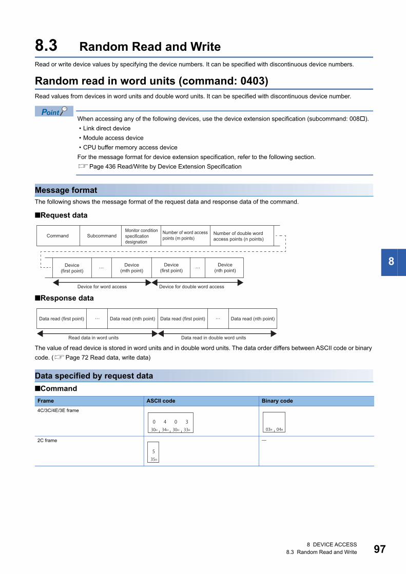
8 DEVICE ACCESS8.3 Random Read and Write 97
8
8.3 Random Read and WriteRead or write device values by specifying the device numbers. It can be specified with discontinuous device numbers.
Random read in word units (command: 0403)Read values from devices in word units and double word units. It can be specified with discontinuous device number.
When accessing any of the following devices, use the device extension specification (subcommand: 008).
• Link direct device
• Module access device
• CPU buffer memory access device
For the message format for device extension specification, refer to the following section.
Page 436 Read/Write by Device Extension Specification
Message formatThe following shows the message format of the request data and response data of the command.
■Request data
■Response data
The value of read device is stored in word units and in double word units. The data order differs between ASCII code or binary
code. (Page 72 Read data, write data)
Data specified by request data
■Command
Frame ASCII code Binary code
4C/3C/4E/3E frame
2C frame
Number of word access points (m points)
Number of double word access points (n points)
Command SubcommandMonitor condition specification designation
Device (first point)
Device (mth point)
Device (first point)
Device (nth point)
Device for word access Device for double word access
Data read (first point) Data read (mth point) Data read (first point) Data read (nth point)
Read data in word units Data read in double word units
030H
434H
030H
333H 03H 04H
535H

988 DEVICE ACCESS8.3 Random Read and Write
■SubcommandThe read timing can be changed by specifying monitor conditions according to the selection of subcommand. (Page 79
Monitor condition specification)
For 2C frame, the specification is not required. Functions and specification methods are equivalent to the subcommands that
do not specify monitor conditions for MELSEC-Q/L series.
When do not specify monitor condition
When specifying a monitoring condition*1
*1 The access targets to which a monitor conditions can be specified have some restrictions. (Page 469 Accessible Modules for Each Command)
At monitor condition specification, use the subcommand 00C0 for the device extension specification. The
message format for device extension specification is the same as that of 008 . Refer to it by substituting 008
to 00C0.
Page 436 Read/Write by Device Extension Specification
■Monitor condition specificationSpecify the conditions for timing to read data. (Page 79 Monitor condition specification)
When do not specify the monitor condition, the specification of this data item is not required.
■Number of word access points, number of double word access pointsSpecify the number of device points to be read within the following range. (Page 70 Access points)
The number of point is specified in the following units depending on device type.
When using subcommand for MELSEC-Q/L series module, calculate it as access points 2 in the following
case.
• When specifying the file register (ZR) of High Performance model QCPU
■DeviceSpecify the device to be read. (Page 65 Devices)
Type ASCII code Binary code
For MELSEC-Q/L series
For MELSEC iQ-R series
Type ASCII code Binary code
For MELSEC-Q/L series
Access target Range
MELSEC iQ-R series module (subcommand: 0000)
MELSEC-Q/L series module (subcommand: 0000)
1 Number of word access points + Number of double word access points
192 points
MELSEC iQ-R series module (subcommand: 0002, 008)
MELSEC-Q/L series module (subcommand: 0080)
MELSEC-QnA series module
Module on other station via MELSEC-QnA series network module
1 Number of word access points + Number of double word access points
96 points
MELSEC-A series module Cannot be used.
Device type Number of word access points Number of double word access points
Bit device 16-point units 32-point units
Word device, double word device 1 word units 2 word units
030H
030H
030H
030H 00H 00H
030H
030H
030H
232H 02H 00H
030H
030H
434H
030H 40H 00H

8 DEVICE ACCESS8.3 Random Read and Write 99
8
The number of points equivalent to the specified 'Number of word access points' and 'Number of double word
access points' is specified for 'Device', respectively. When '0' is specified for the access points, this
specification is not required.
The following devices cannot be specified.
• Long timer (contact: LTS, coil: LTC)
• Long retentive timer (contact: LSTS, coil: LSTC)
• Long counter (contact: LCS, coil: LCC)
Page 69 Considerations when accessing long timer, long retentive timer, or long counter

1008 DEVICE ACCESS8.3 Random Read and Write
Communication example (Monitor condition is not specified)Read values of D0, T0, M100 to M115, X20 to X2F with word access. Read values of D1500 to D1501, Y160 to Y17F, M1111
to M1142 with 4 double word access. (Subcommand: for MELSEC-Q/L series)
D0 = 6549 (1995H), T0 = 4610 (1202H), D1500 = 20302 (4F4EH), D1501 = 19540 (4C54H) are stored.
■Data communication in ASCII code(Request data)
(Response data)
0 4 0 330H 34H 30H 33H
0 0 030H 30H 30H
0 0 430H 30H 34H
0 330H 33H
D44H
* 0 02AH 30H 30H
0 0 030H 30H 30H
030H
T54H
N 0 04EH 30H 30H
0 0 030H 30H 30H
030H
M4DH
* 0 02AH 30H 30H
0 1 030H 31H 30H
030H
X58H
* 0 02AH 30H 30H
0 0 230H 30H 32H
030H
D44H
* 0 02AH 30H 30H
1 5 031H 35H 30H
030H
Y59H
* 0 02AH 30H 30H
0 1 630H 31H 36H
030H
M4DH
* 0 02AH 30H 30H
1 1 131H 31H 31H
131H
Number of double word
access points
Number of word
access pointsSubcommand
Device for word accessDevice code
Device code
Device code
Device codeDevice number Device number Device number Device number
Device for double word accessDevice code
Device code
Device codeDevice number Device number Device number
131H
9 9 539H 39H 35H
1 2 031H 32H 30H
232H
232H
0 3 030H 33H 30H
4 8 434H 38H 34H
939H
D0 T0
434H
C 5 443H 35H 34H
4 F 434H 46H 34H
E45H
C43H
3 D E33H 44H 45H
B 9 A42H 39H 41H
F46H
B42H
A D D41H 44H 44H
B C B42H 43H 42H
737H
D1501 D1500
1 1 0 0 0 0 1 0 1 1 1 1
C F
1 0 1 1 1 0 1 0 1 0 1 1 0 1 1 1
B B 7
0
4
1 0 0 1 0 0 0 0 1 0 0 1 0 0 1
8 4 9
0
2
0 1 0 0 0 0 0 0 0 1 1 0 0 0 0
0 3 0
M115 M100
0 OFF1 ON
0 OFF1 ON
X2F X20
Y17F Y160
M1142 M1111
M115 M100 X2F X20
Y17F Y160 M1142 M1111
0 OFF1 ON
0 OFF1 ON
to to
to to
Read data 1in word units
Read data 1in double word units
Read data 2in double word units
Read data 3in double word units
Read data 3 in word units
Read data 4 in word units
Read data 2 in double word units
Read data 3 in double word units
Read data 4in word units
Read data 3in word units
Read data 2in word units
to
to to
to
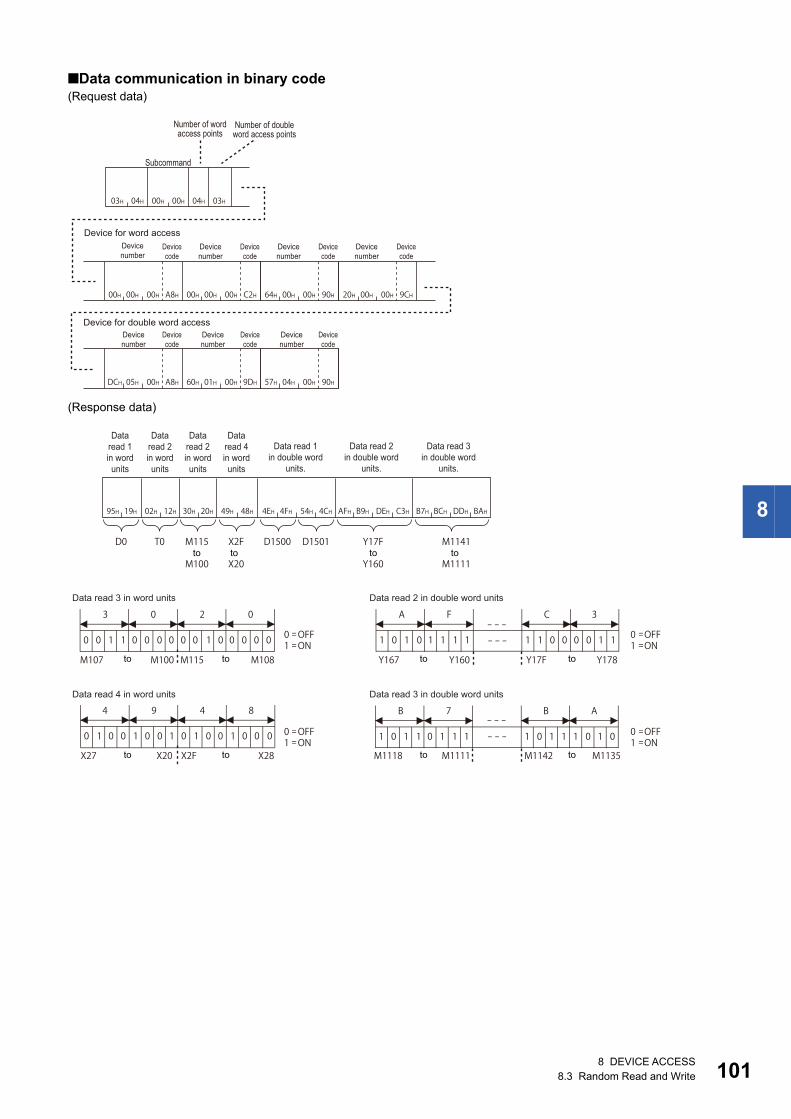
8 DEVICE ACCESS8.3 Random Read and Write 101
8
■Data communication in binary code(Request data)
(Response data)
03H 04H 00H 00H 04H 03H
00H 00H 00H A8H 00H 00H 00H C2H 64H 00H 00H 90H 20H 00H 00H 9CH
DCH 05H 00H A8H 60H 01H 00H 9DH 57H 04H 00H 90H
Number of word access points
Number of double word access points
Subcommand
Device for word accessDevice number
Device code
Device number
Device code
Device number
Device code
Device number
Device code
Device for double word accessDevice number
Device code
Device number
Device code
Device number
Device code
Data read 1in word units
Data read 2in word units
Data read 2in word units
Data read 4in word units
Data read 1 in double word
units.
Data read 2 in double word
units.
Data read 3 in double word
units.
Data read 3 in word units Data read 2 in double word units
Data read 4 in word units Data read 3 in double word units
to to to to
to toto to
to toto to
95H 19H 02H 12H 30H 20H 49H 48H 4EH 4FH 54H 4CH AFH B9H DEH C3H B7H BCH DDH BAH
D0 T0
0
3
0 1 1 0 0 0 0 0 0 1 0 0 0 0 0
0 2 0
0
4
1 0 0 1 0 0 1 0 1 0 0 1 0 0 0
9 4 8
D1500 D1501
1
A
0 1 0 1 1 1 1 1 1 0 0 0 0 1 1
F C 3
1
B
0 1 1 0 1 1 1 1 0 1 1 1 0 1 0
7 B A
M107 M100
0 OFF1 ON
0 OFF1 ON
0 OFF1 ON
0 OFF1 ON
M115 M108 Y167 Y160
M1118 M1111 M1142 M1135
Y17F Y178
X27 X20 X2F X28
M115
M100
Y17F
Y160
X2F X20
M1141
M1111

1028 DEVICE ACCESS8.3 Random Read and Write
Communication example (Monitor condition is specified)Read values of D0, T0, M100 to M115, X20 to X2F with word access. Read values of D1500 to D1501, Y160 to Y17F, M1111
to M1142 with 4 double word access.
The monitor condition is as follows: When the value of link register (W100) reached '7BH' (123) while the step No.1000 of
program file CONB1.QPG is being executed.
■Data communication in ASCII code(Request data)
(Response data)
It is the same as the communication example when monitor condition is not specified. (Page 100 Data communication in
ASCII code)
File No. File name
File designation
Attribute
Step No.
SFC designation ( not specified )
Extension
Step No.Block No.SFC pattern
Monitor condition
Monitor condition value
Mask value
Word device value designation Bit device value designation ( Fixed value for dummy )
Number of word
access points
Number of double word
access points
Device for word access
Device for double word access
Subcommand
Monitor condition value
Device code
Device number
Device code
Device number
30H 34H 30H 33H 30H 30H 34H 30H 30H 33H 30H 46H
44H 2AH 30H 30H 30H 30H 30H 30H 54H 4EH 30H 30H 30H 30H 30H 30H 4DH 2AH 30H 30H 30H 31H 30H 30H 58H 2AH 30H 30H 30H 30H 32H 30H
44H 2AH 30H 30H 31H 35H 30H 30H 59H 2AH 30H 30H 30H 31H 36H 30H 4DH 2AH 30H 30H 31H 31H 31H 31H
30H 34H 30H 33H
30H 31H 20H30H 30H
30H 30H30H 30H 30H 30H30H 30H 30H 30H30H 30H 30H 30H30H 30H 45H 38H30H 33H
30H 30H4DH 2AH 30H 30H30H 30H 30H 30H30H 30H57H 2AH 30H 30H30H 31H 46H 37H 42H30H 30H
43H 42H 51H 47H50H20H20H20H31H4EH4FH
46H46H46H
0 4 0 3 0 0 4 0 0 3 0 F
D * 0 0 0 0 0 0 T N 0 0 0 0 0 0 M * 0 0 0 1 0 0 X * 0 0 0 0 2 0
D * 0 0 1 5 0 0 Y * 0 0 0 1 6 0 M * 0 0 1 1 1 1
0 4 0 3
C O N B 1 Q P G0 0 0 1
0 0 0 0 0 0 0 0 0 0 0 0 0 0 0 0 3 E 80
M * 0 0 0 0 0 0 0 0W * 0 0 0 1 0 0 F 0 0 7 BFFF

8 DEVICE ACCESS8.3 Random Read and Write 103
8
■Data communication in binary code(Request data)
(Response data)
It is the same as the communication example when monitor condition is not specified. (Page 101 Data communication in
binary code)
File No. File name
File designation
Attribute Step No.
SFC designation ( not specified )
Extension Step No. Block No.SFC
patternMonitor condition
Monitor condition value
Mask value
Word device value designation Bit device value designation ( Fixed value for dummy )
Number of word access points
Number of double word access points
Device for word access
Device for double word access
Subcommand
Monitor condition value
Device code
Device number
Device code
Device number
03H 04H 40H 00H
04H 03H 00H 00H 00H A8H 00H 00H 00H C2H 64H 00H 00H 90H 20H 00H 00H 9CH
DCH 05H 00H A8H 60H 01H 00H 9DH 57H 04H 00H 90H
C O N B 1 Q P G01H 00H 43H 42H 51H 47H50H 00H 00H 00H 00H 00H 00H20H20H20H31H4EH4FH 20H E8H 00H00H03H03H 0FH
00H 00H 00H 00H90H00H 01H 00H B4H FFH FFH 7BH 00H

1048 DEVICE ACCESS8.3 Random Read and Write
Random write in word units (test) (command: 1402)Write values to devices in word units and double word units. It can be specified with discontinuous device numbers.
When accessing any of the following devices, use the device extension specification (subcommand: 008).
• Link direct device
• Module access device
• CPU buffer memory access device
For the message format for device extension specification, refer to the following section.
Page 436 Read/Write by Device Extension Specification
Message formatThe following shows the message format of the request data and response data of the command.
■Request data
■Response dataThere is no response data for this command.
Data specified by request data
■Command
■Subcommand
For 2C frame, the specification is not required. Functions and specification methods are equivalent to the subcommands for
MELSEC-Q/L series.
Frame ASCII code Binary code
4C/3C/4E/3E frame
2C frame
Type ASCII code Binary code
For MELSEC-Q/L series
For MELSEC iQ-R series
Number of word access points (m points)
Number of double word access points (n points)
Command Subcommand
Write data (nth point)Device (first point) Write data (first point) Device (mth point)
Device for word access
Device (first point) Write data (first point) Device (nth point) Write data (nth point)
Device for double word access
131H
434H
030H
232H 02H 14H
737H
030H
030H
030H
030H 00H 00H
030H
030H
030H
232H 02H 00H

8 DEVICE ACCESS8.3 Random Read and Write 105
8
■Number of word access points, number of double word access pointsSpecify the number of device points to be written within the following range. (Page 70 Access points)
The number of point is specified in the following units depending on device type.
■DeviceSpecify a device to be written. (Page 65 Devices)
Set the head device number with a multiple of 16 for bit device access of MELSEC-A series module.
■Write dataSpecify the values to be written to device. (Page 72 Read data, write data)
Specify the write data in hexadecimal.
Specify 'Device' and 'Write data' with number of points which are specified in 'Number of word access points'
and 'Number of double word access points'. When the access point is set to '0', the specification is not
required.
Communication exampleWrite values to devices as follows. (Subcommand: for MELSEC-Q/L series)
Access target Range
MELSEC iQ-R series module (subcommand: 0000)
MELSEC-Q/L series module (subcommand: 0000)
1 (Number of word access points 12) + (Number of double word access
points 14) 1920 points
MELSEC iQ-R series module (subcommand: 0002, 008)
MELSEC-Q/L series module (subcommand: 0080)
MELSEC-QnA series module
Module on other station via MELSEC-QnA series network module
1 (Number of word access points 12) + (Number of double word access
points 14) 960 points
MELSEC-A series module 1 Number of word access points 10 points
Device type Number of word access points Number of word access points
Bit device 16-point units 32-point units
Word device, double word device 1 word units 2 word units
Item Device to be written
Word access D0, D1, M100 to M115, X20 to X2F
Double word access D1500 to D1501, Y160 to Y17F, M1111 to M1142
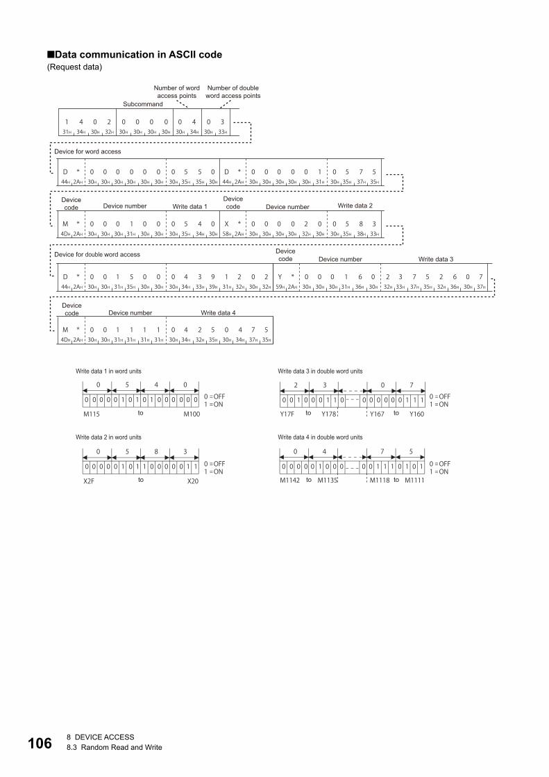
1068 DEVICE ACCESS8.3 Random Read and Write
■Data communication in ASCII code(Request data)
1 4 0 231H 34H 30H 32H
0 0 030H 30H 30H
0 0 430H 30H 34H
0 330H 33H
D44H
* 0 02AH 30H 30H
0 0 030H 30H 30H
030H
030H
5 5 035H 35H 30H
D44H
* 0 02AH 30H 30H
0 0 030H 30H 30H
131H
030H
5 7 535H 37H 35H
M4DH
* 0 02AH 30H 30H
0 1 030H 31H 30H
030H
030H
5 4 035H 34H 30H
X58H
* 0 02AH 30H 30H
0 0 230H 30H 32H
030H
030H
5 8 335H 38H 33H
D44H
* 0 02AH 30H 30H
1 5 031H 35H 30H
030H
030H
4 3 934H 33H 39H
131H
2 0 232H 30H 32H
Y59H
* 0 02AH 30H 30H
0 1 630H 31H 36H
030H
232H
3 7 533H 37H 35H
232H
6 0 736H 30H 37H
M4DH
* 0 02AH 30H 30H
1 1 131H 31H 31H
131H
030H
4 2 534H 32H 35H
030H
4 7 534H 37H 35H
0 0 0 0 0 1 0 1 0 1 0 0 0 0 0 0
0 0 0 0 0 1 0 1 1 0 0 0 0 0 1 1
0 0 1 0 0 0 1 1 0 0 0 0 0 0 0 1 1 1
0 0 0 0 1 0 0 0 0 0 1 1 1 0 1 0 10
0 OFF1 ON
0 OFF1 ON
0 OFF1 ON
0 OFF1 ON
X2F X20 M1142 M1135 M1118 M1111
0 5 4 0
0 5 8 3
2 3 0 7
0 4 7 5
M115 M100 Y17F Y178 Y167 Y160
Number of word access points
Number of double word access points
Subcommand
Device code Device number Write data 1
Device code Device number Write data 2
Device code Device number Write data 3
Device code Device number Write data 4
Device for word access
Device for double word access
Write data 1 in word units
Write data 2 in word units
Write data 3 in double word units
Write data 4 in double word units
to
to to
to
to
to

8 DEVICE ACCESS8.3 Random Read and Write 107
8
■Data communication in binary code(Request data)
Number of word access points
Number of double word access points
Subcommand
Device code
Device number
Write data 1
Device code
Device number
Write data 2
Device code
Device number
Write data 3
Device code
Device number
Write data 4
Device for word access
Device for double word access
Write data 1 in word units
Write data 2 in word units
Write data 3 in double word units
Write data 4 in double word units
to toto to
02H 14H 03H04H00H 00H
00H 00H 00H A8H 50H 05H 01H 00H 00H A8H 75H 05H 64H 00H 00H 90H 40H 05H 20H 00H 00H 9CH 83H 05H
DCH 05H 00H A8H 02H 12H 39H 04H 60H 01H 00H 9DH 07H 26H 75H 23H 57H 04H 00H 90H 75H 04H 25H 04H
0 1 0 0 0 0 0 0 0 0 0 0 0 1 0 1
1 0 0 0 0 0 1 1 0 0 0 0 0 1 0 1
0 0 0 0 0 1 1 1 0 1 0 0 1 0 0 0 1 1
0 1 1 1 0 1 0 1 0 1 0 0 0 0 0 1 0 0
0 10 OFF1 ON
0 OFF1 ON
0 OFF1 ON
0 OFF1 ON
4 0 0
M107 M100 M115 M108 Y167 Y160 Y17F Y178
5 0 7 2 3
7 5 0 48 3 0 5

1088 DEVICE ACCESS8.3 Random Read and Write
Random write in bit units (test) (command: 1402)Write values to devices in bit units. It can be specified with discontinuous device number.
When accessing any of the following devices, use the device extension specification (subcommand: 008).
• Link direct device
• Module access device
• CPU buffer memory access device
For the message format for device extension specification, refer to the following section.
Page 436 Read/Write by Device Extension Specification
Message formatThe following shows the message format of the request data and response data of the command.
■Request data
■Response dataThere is no response data for this command.
Request data
■Command
■Subcommand
For 2C frame, the specification is not required. Functions and specification methods are equivalent to the subcommands for
MELSEC-Q/L series.
■Number of bit access pointsSpecify the number of device points to be written within the following range. (Page 70 Number of device points)
Frame ASCII code Binary code
4C/3C/4E/3E frame
2C frame
Type ASCII code Binary code
For MELSEC-Q/L series
For MELSEC iQ-R series
Access target Range
MELSEC iQ-R series module (subcommand: 0001)
MELSEC-Q/L series module (subcommand: 0001)
1 to 188 points
MELSEC iQ-R series module (subcommand: 0003, 008)
MELSEC-Q/L series module (subcommand: 0081)
MELSEC-QnA series module
Module on other station via MELSEC-QnA series network module
1 to 94 points
MELSEC-A series module 1 to 20 points
Device(first point)
Set/reset(first point)
Device(nth point)
Set/reset(nth point)Command Subcommand Number of bit access
points (n points)
131H
434H
030H
232H 02H 14H
636H
030H
030H
030H
131H 01H 00H
030H
030H
030H
333H 03H 00H

8 DEVICE ACCESS8.3 Random Read and Write 109
8
■DeviceSpecify a device to be written. (Page 65 Devices)
Specify a bit device.
■Set/resetSpecify the ON/OFF status of bit devices. (Page 78 Set/reset)
The number of points equivalent to the specified "Number of bit access points" is specified for "Device" and
"Set/reset", respectively.
Communication exampleTurn M50 OFF, and turn Y2F ON. (Subcommand: for MELSEC-Q/L series)
■Data communication in ASCII code(Request data)
■Data communication in binary code(Request data)
1 4 0 231H 34H 30H 32H
0 0 030H 30H 30H
1 0 231H 30H 32H
M4DH
* 0 02AH 30H 30H
0 0 530H 30H 35H
030H
030H
030H
Y59H
* 0 02AH 30H 30H
0 0 230H 30H 32H
F46H
030H
131H
Number of bit
access points Set/reset Set/resetDevice code
Device codeSubcommand Device number Device number
02H 14H 01H 00H 02H 32H 00H 00H 90H 00H 2FH 00H 00H 9DH 01H
Number of bit access points Set/reset Set/reset
Device code
Device code
Subcommand Device number Device number

1108 DEVICE ACCESS8.4 Batch Read and Write Multiple Blocks
8.4 Batch Read and Write Multiple Blocks Read or write values for specified multiple blocks by handling consecutive devices as one block.
Batch read multiple blocks (command: 0406)Read values for specified multiple blocks by handling consecutive word devices or bit devices as one block.
Each block can be specified with discontinuous device numbers.
When communicating with a Universal model QCPU or an LCPU, if other than "Specify service process
execution counts" is selected for "Service Processing Setting" of the CPU module, data separation may occur.
To avoid data separation, select "Specify service process execution counts".
When accessing any of the following devices, use the device extension specification (subcommand: 008).
• Link direct device
• Module access device
• CPU buffer memory access device
For the message format for device extension specification, refer to the following section.
Page 436 Read/Write by Device Extension Specification
Message formatThe following shows the message format of the request data and response data of the command.
■Request data
■Response dataThe value of read device is stored in hexadecimal. The data order differs between ASCII code or binary code. (Page 72
Read data, write data)
Data specified by request data
■Command
ASCII code Binary code
Number of word device blocks(m points)
Number of bitdevice blocks (n points)
Block of word device(first point)
Block of word device(mth point)
Command Subcommand
Block of bit device(first point)
Block of bit device(nth point)
Data for the number of word device blocks Data for the number of bit device blocks
Word device Bit device
Data in the first block
Data in the mth block
Data in the first block
Data in the nth block
030H
434H
030H
636H 06H 04H

8 DEVICE ACCESS8.4 Batch Read and Write Multiple Blocks 111
8
■Subcommand
■Number of word device blocks, number of bit device blocksSpecify the number of device blocks to be read in hexadecimal. (Page 71 Number of blocks)
Specify the total number of each block within the following range.
■Block of word device, block of bit deviceSpecify the device to be read by handling consecutive devices as one block.
Specify the block with the number of points equivalent to the specified "Number of word device blocks" and
"Number of bit device blocks", respectively. When '0' is specified, this specification is not required.
Specify the following items for every block.
• Device: Specify the head device of the consecutive devices. (Page 65 Devices)
• Number of device points: Specify the number of device points to be read. (Page 70 Number of device points)
Specify the total number of device points for each block within the range of 1 to 960.
Word device is 1-word per one point, and bit device is 16-bit for one point.
Use a bit device block when the contact and coil for the following devices are specified.
• Timer
• Retentive timer
• Counter
The following devices cannot be specified.
• Long timer (contact: LTS, coil: LTC, current value: LTN)
• Long retentive timer (contact: LSTS, coil: LSTC, current value: LSTN)
• Long counter (contact: LCS, coil: LCC, current value: LCN)
• Long index register (LZ)
Page 69 Considerations when accessing long timer, long retentive timer, or long counter
Page 69 Considerations when accessing long index register
Type ASCII code Binary code
For MELSEC-Q/L series
For MELSEC iQ-R series
Access target Range
MELSEC iQ-R series module (subcommand: 0000)
MELSEC-Q/L series module (subcommand: 0000)
MELSEC-QnA series module
1Number of word device blocks + Number of bit device blocks 120 points
MELSEC iQ-R series module (subcommand: 0002, 008)
MELSEC-Q/L series module (subcommand: 0080)
1Number of word device blocks + Number of bit device blocks60 points
030H
030H
030H
030H 00H 00H
030H
030H
030H
232H 02H 00H
Block (1 point)Number of
device pointsHead device

1128 DEVICE ACCESS8.4 Batch Read and Write Multiple Blocks
Communication exampleRead values from device as follows. (Subcommand: for MELSEC-Q/L series)
■Data communication in ASCII code(Request data)
(Response data)
Item Content to be read
Word device Block 1: D0 to D3 (4 points)
Block 2: W100 to W107 (8 points)
Bit device Block 1: M0 to M31 (2 points)
Block 2: M128 to M159 (2 points)
Block 3: B100 to B12F (3 points)
0 4 0 630H 34H 30H 36H
0 0 030H 30H 30H
0 0 230H 30H 32H
0 330H 33H
D44H
* 0 02AH 30H 30H
0 0 030H 30H 30H
030H
030H
0 0 430H 30H 34H
W57H
* 0 02AH 30H 30H
0 1 030H 31H 30H
030H
030H
0 0 830H 30H 38H
M4DH
* 0 02AH 30H 30H
0 0 030H 30H 30H
030H
030H
0 0 230H 30H 32H
M4DH
* 0 02AH 30H 30H
0 1 230H 31H 32H
838H
030H
0 0 230H 30H 32H
B42H
* 0 02AH 30H 30H
0 1 030H 31H 30H
030H
030H
0 0 330H 30H 33H
Number of word device blocks
Number of bitdevice blocks
Subcommand
Device code
Device codeDevice number
Number of device points Device number
Number of device points
Device code
Device codeDevice number
Number of device points Device number
Number of device points
Device code Device number
Number of device points
030H
0 0 830H 30H 38H
2 0 332H 30H 33H
030H
131H
5 4 535H 34H 35H
2 8 032H 38H 30H
030H
030H
9 7 039H 37H 30H
0 1 330H 31H 33H
131H
D0 D1 D2 D3 W100 W107
232H
0 3 030H 33H 30H
4 8 434H 38H 34H
939H
C43H
3 D E33H 44H 45H
2
0
2 0 03
0 1 0 0 0 0 00 0 0 0 0 0 1 1
8 032H 38H 30H
030H
030H
9 7 039H 37H 30H
B42H
9 A F39H 41H 46H
B42H
9 A F39H 41H 46H
M15 M0 M31 M16 M143 M128 M159 M144 B10F B100 B11F B110 B12F B120
M15 M0
0 = OFF1 = ON
Word device Data in the first block
Word device Data in the second block
to
to to
to
to to to to to
Bit deviceData in the first block
Bit deviceData in the second block
Bit deviceData in the third block
M15 Bit order of M0

8 DEVICE ACCESS8.4 Batch Read and Write Multiple Blocks 113
8
■Data communication in binary code(Request data)
(Response data)
06H 04H 00H 00H 02H 03H
00H 00H 04H 00H00H A8H 00H 01H 08H 00H00H B4H 00H 00H 02H 00H00H 90H 80H 00H 02H 00H00H 90H 00H 01H 03H 00H00H A0H
Number of word device blocks
Number of bitdevice blocks
Subcommand
Device code
Number of device points
Device code
Number of device points
Device code
Number of device points
Device code
Number of device points
Device code
Number of device pointsDevice number Device number Device number Device number Device number
08H 00H 30H 20H 45H 15H 00H 28H 70H 09H 31H 01H 30H 20H 49H 48H DEH C3H 00H 28H 70H 09H AFH B9H AFH B9H
D0 D1 D2 D3 W100 M15
M0
W107 M31
M16
M143
M128
M159
M144
B10F
B100
B11F
B110
B12F
B120
0
3 0 02
0 1 1 0 0 0 00 0 0 0 0 0 1 00 = OFF1 = ON
M7 M0 M15 M8
Bit deviceData in the first
block
Bit deviceData in the
second blockBit device
Data in the third blockWord device
Data in the first blockWord device
Data in the second block
M15 Bit order of M0
toto to to to to
to to
to to

1148 DEVICE ACCESS8.4 Batch Read and Write Multiple Blocks
Batch write multiple blocks (command: 1406)Write values for specified multiple blocks by handling consecutive word devices or bit devices as one block.
Each block can be specified with discontinuous device numbers.
When communicating with a Universal model QCPU or an LCPU, if other than "Specify service process
execution counts" is selected for "Service Processing Setting" of the CPU module, data separation may occur.
To avoid data separation, select "Specify service process execution counts".
When accessing any of the following devices, use the device extension specification (subcommand: 008).
• Link direct device
• Module access device
• CPU buffer memory access device
For the message format for device extension specification, refer to the following section.
Page 436 Read/Write by Device Extension Specification
Message formatThe following shows the message format of the request data and response data of the command.
■Request data
■Response dataThere is no response data for this command.
Data specified by request data
■Command
■Subcommand
■Number of word device blocks, number of bit device blocksSpecify the number of device blocks to be written in hexadecimal. (Page 71 Number of blocks)
ASCII code Binary code
Type ASCII code Binary code
For MELSEC-Q/L series
For MELSEC iQ-R series
Number of word device blocks(m points)
Number of bitdevice blocks (n points)
Block of word device(first point)
Block of word device(mth point)
Command Subcommand
Block of bit device(first point)
Block of bit device(nth point)
131H
434H
030H
636H 06H 14H
030H
030H
030H
030H 00H 00H
030H
030H
030H
232H 02H 00H

8 DEVICE ACCESS8.4 Batch Read and Write Multiple Blocks 115
8
Specify the total number of each block within the following range.
■Block of word device, Block of bit deviceSpecify the device to be written by handling consecutive devices as one block.
Specify the block with the number of points equivalent to the specified "Number of word device blocks" and
"Number of bit device blocks", respectively. When '0' is specified, this specification is not required.
Specify the following items for each block.
• Device: Specify the head device of the consecutive devices. (Page 65 Devices)
• Number of device points: Specify the number of device points to be written. (Page 70 Number of device points)
• Write data: Specify the data to be written for the number of device points in hexadecimal. (Page 72 Read data, write
data)
Specify the number of device points within the following range.
Word device is 1-word per one point, and bit device is 16-bit for one point.
Use a bit device block when the contact and coil for the following devices are specified.
• Timer
• Retentive timer
• Counter
The following devices cannot be specified.
• Long timer (contact: LTS, coil: LTC, current value: LTN)
• Long retentive timer (contact: LSTS, coil: LSTC, current value: LSTN)
• Long counter (contact: LCS, coil: LCC, current value: LCN)
• Long index register (LZ)
Page 69 Considerations when accessing long timer, long retentive timer, or long counter
Page 69 Considerations when accessing long index register
Access target Range
MELSEC iQ-R series module (subcommand: 0000)
MELSEC-Q/L series module (subcommand: 0000)
MELSEC-QnA series module
1Number of word device blocks + Number of bit device blocks120 points
MELSEC iQ-R series module (subcommand: 0002, 008)
MELSEC-Q/L series module (subcommand: 0080)
1Number of word device blocks + Number of bit device blocks60 points
Subcommand Range
When using MELSEC-Q/L series (0000, 0080) 1 (Total number of each block4) + (Total number of device)960 points
When using MELSEC iQ-R series (0002, 0082) 1(Total number of each block9) + (Total number of device)960 points
Block (1 point)Number of
device points Write dataHead device

1168 DEVICE ACCESS8.4 Batch Read and Write Multiple Blocks
Communication exampleWrite values to devices as follows. (Subcommand: for MELSEC-Q/L series)
■Data communication in ASCII code(Request data)
1 4 0 631H 34H 30H 36H
0 0 030H 30H 30H
0 0 230H 30H 32H
0 330H 33H
D44H
* 0 02AH 30H 30H
0 0 030H 30H 30H
030H
030H
0 0 430H 30H 34H
030H
0 0 830H 30H 38H
232H
8 0 038H 30H 30H
W57H
* 0 02AH 30H 30H
0 1 030H 31H 30H
030H
030H
0 0 830H 30H 38H
M4DH
* 0 02AH 30H 30H
0 0 030H 30H 30H
030H
030H
0 0 230H 30H 32H
M4DH
* 0 02AH 30H 30H
0 1 230H 31H 32H
838H
030H
0 0 230H 30H 32H
B42H
* 0 02AH 30H 30H
0 1 030H 31H 30H
030H
030H
0 0 330H 30H 33H
030H
9 7 039H 37H 30H
B42H
9 A F39H 41H 46H
030H
9 7 039H 37H 30H
030H
1 3 131H 33H 31H
232H
0 3 030H 33H 30H
432H
8 4 938H 34H 39H
C43H
3 D E33H 44H 45H
232H
8 0 038H 30H 30H
D0
M15 M0
D3
M31 M16
M143 M128
B10F B100 B12F B120
M159 M144
W100 W107
1
B 9 FA
0 1 1 1 1 1 11 0 0 1 1 0 1 0 0 = OFF1 = ON
B12F B120
Subcommand
Device code Device number
Number of device points Write data
Number of word device blocks
Number of bit device blocks
to to
to to
Device code Device number
Number of device points Write data
Device code Device number
Number of device points Write data
Device code Device number
Number of device points Write data
Device code Device number
Number of device points Write data
to to
to
to
to
to
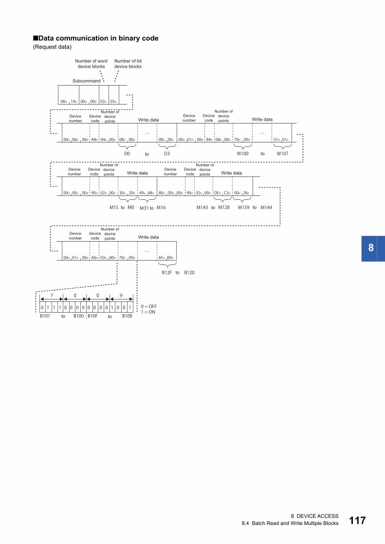
8 DEVICE ACCESS8.4 Batch Read and Write Multiple Blocks 117
8
■Data communication in binary code(Request data)
06H 14H 00H 00H 02H 03H
00H 00H 00H A8H 04H 00H 08H 00H 00H 28H 00H 01H 00H B4H 08H 00H 70H 09H 31H 01H
00H 00H 00H 90H 02H 00H 30H 20H 49H 48H 80H 00H 00H 90H 02H 00H DEH C3H 00H 28H
00H 01H 00H A0H 03H 00H 70H 09H AFH B9H
D0
M15 M0
B12F B120
M31 M16 M143 M128 M159 M144
D3 W100 W107
0
7 0 90
1 1 1 1 0 0 10 0 0 0 0 0 0 0 0 = OFF1 = ON
B107 B100 B10F B108
Device code
Device number
Number of device points Write data
Number of word device blocks
Number of bit device blocks
Subcommand
Device code
Device number
Number of device points Write data
Device code
Device number
Number of device points Write data
Device code
Device number
Number of device points Write data
Device code
Device number
Number of device points Write data
to to
to to to to
to
to to
1188 DEVICE ACCESS8.5 Device Memory Monitor
8.5 Device Memory MonitorRead the registered device data, and monitor it.
Monitoring procedureThe following shows the procedure to monitor devices.
1. Registration of monitor device
Register a device to be read. (Page 119 Register monitor data (command: 0801))
2. Execution of monitor
Read values from a registered device. (Page 120 Monitor (command: 0802))
3. Registration of monitor devices
Reregister a device when a device to be read is changed. (Page 119 Register monitor data (command: 0801))
• Monitoring with multiple conditions to the device memory of the same CPU module cannot be performed at
the same time. If monitor (command: 0802) is executed while monitor with other conditions is being
performed, the command is completed abnormally.
• Register devices to be read with the 'register monitor data' (command: 0801) before executing the 'monitor'
(command: 0802). If the 'monitor' (command: 0802) is executed without the registration, the command is
completed abnormally.
• When the access target module is restarted, the registered content is deleted. Register the devices to be
read again with the 'register monitor data' (command: 0801).

8 DEVICE ACCESS8.5 Device Memory Monitor 119
8
Register monitor data (command: 0801)Register devices to be monitored.
Message formatThe following shows the message format of the request data and response data of the command.
■Request data
■Response dataThere is no response data for this command.
Data specified by request data
■Command
The data other than commands is the same as the data specified by 'random read in word units' (command: 0403).
Page 97 Random read in word units (command: 0403)
Frame ASCII code Binary code
4C/3C/4E/3E frame
2C frame
Number of word access points (m points)
Number of double word access points (n points)
Command SubcommandMonitor condition specification designation
Device (first point)
Device (mth point)
Device (first point)
Device (nth point)
Device for double word accessDevice for word access
030H
838H
030H
131H 01H 08H
838H
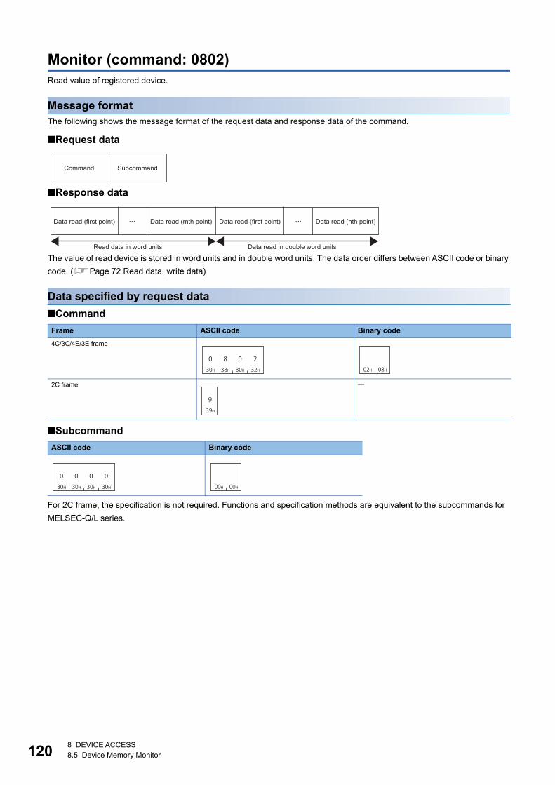
1208 DEVICE ACCESS8.5 Device Memory Monitor
Monitor (command: 0802)Read value of registered device.
Message formatThe following shows the message format of the request data and response data of the command.
■Request data
■Response data
The value of read device is stored in word units and in double word units. The data order differs between ASCII code or binary
code. (Page 72 Read data, write data)
Data specified by request data
■Command
■Subcommand
For 2C frame, the specification is not required. Functions and specification methods are equivalent to the subcommands for
MELSEC-Q/L series.
Frame ASCII code Binary code
4C/3C/4E/3E frame
2C frame
ASCII code Binary code
Command Subcommand
Data read (first point) Data read (mth point) Data read (first point) Data read (nth point)
Read data in word units Data read in double word units
030H
838H
030H
232H 02H 08H
939H
030H
030H
030H
030H 00H 00H

8 DEVICE ACCESS8.5 Device Memory Monitor 121
8
Communication exampleRead the following devices registered by the 'register monitor data' (command: 0801).
• Word access: D0, T0, M100 to M115, X20 to X2F
• Double word access: D1500 to D1501, Y160 to Y17F, M1111 to M1142
D0 = 6549 (1995H), T0 = 4610 (1202H), D1500 = 20302 (4F4EH), D1501 = 19540 (4C54H) are stored.
■Data communication in ASCII code(Request data)
(Response data)
0 8 0 230H 38H 30H 32H
0 0 030H 30H 30H
030H
to to
to to
Read data 1in word units
Read data 1in double word units
Read data 2in double word units
Read data 3in double word units
Read data 3 in word units
Read data 4 in word units
Read data 2 in double word units
Read data 3 in double word units
Read data 4in word units
Read data 3in word units
Read data 2in word units
to
to to
to
131H
9 9 539H 39H 35H
1 2 031H 32H 30H
232H
232H
0 3 030H 33H 30H
4 8 434H 38H 34H
939H
D0 T0 M115 M100 X2F X20
434H
C 5 443H 35H 34H
4 F 434H 46H 34H
E45H
C43H
3 D E33H 44H 45H
B 9 A42H 39H 41H
F46H
B42H
A D D41H 44H 44H
B C B42H 43H 42H
737H
D1501 D1500 Y17F Y160 M1142 M1111
1 1 0 0 0 0 1 0 1 1 1 1
C F
1 0 1 1 1 0 1 0 1 0 1 1 0 1 1 1
B B 7
0
4
1 0 0 1 0 0 0 0 1 0 0 1 0 0 1
8 4 9
0
2
0 1 0 0 0 0 0 0 0 1 1 0 0 0 0
0 3 0
M115 M100
0 OFF1 ON
0 OFF1 ON
0 OFF1 ON
0 OFF1 ON
X2F X20
Y17F Y160
M1142 M1111

1228 DEVICE ACCESS8.5 Device Memory Monitor
■Data communication in binary code(Request data)
(Response data)
02H 08H 00H 00H
95H 19H 02H 12H 30H 20H 49H 48H 4EH 4FH 54H 4CH AFH B9H DEH C3H B7H BCH DDH BAH
D0 T0 M115
M100
Y17F Y160
0
3
0 1 1 0 0 0 0 0 0 1 0 0 0 0 0
0 2 0
0
4
1 0 0 1 0 0 1 0 1 0 0 1 0 0 0
9 4 8
D1500 D1501X2F X20
M1142 M1111
1
A
0 01 1 1 1 1 1 1 0 0 0 0 1 1
F C 3
1
B
0 1 1 0 1 1 1 1 0 1 1 1 0 1 0
7 B A0 OFF1 ON
0 OFF1 ON
0 OFF1 ON
0 OFF1 ON
M107 M100 M115 M108 Y167 Y160 Y17F Y178
M1118 M1111 M1142 M1135X27 X20 X2F X28
Data read 1in word units
Data read 2in word units
Data read 3in word units
Data read 4in word units
Data read 1 in double word
units
Data read 2in double word
units
Data read 3in double word
units
to toto to
Data read 3 in word units Data read 2 in double word units
to toto to
to toto to
Data read 4 in word units Data read 3 in double word units

9 LABEL ACCESS9.1 Data to be Specified in Commands 123
99 LABEL ACCESS
This section explains the commands to read and write devices using the standard global label of GX Works3.
The commands can be used when the connected station and request target is MELSEC iQ-R series module.
• Local labels and module labels cannot be accessed.
• The global labels set with GX Works2 cannot be accessed.
• Safety global labels, safety local labels, and standard/safety shared global labels of the safety CPU cannot
be accessed.
• Enable "Access from External Device" with the global label setting editor of GX Works3 at the time of label
access. (Disabled by default.)
9.1 Data to be Specified in CommandsThis section explains the contents and specification methods for data items which are set in each command related to label
access.
LabelsSpecify the global label name to be accessed.
The "Label name" is specified by variable length. Specify the length of character string by "Label name length". (Null is
unnecessary at the end of a label name character string.)
Label name lengthSpecify the number of characters of a label name.
■Data communication in ASCII codeConvert the numerical value to 4-digit ASCII code (hexadecimal), and send it from the upper digits.
■Data communication in binary codeSend 2-byte*1 numerical values from lower byte (L: bits 0 to 7).
*1 For C24, the additional code may be added. (Page 35 Additional code (10H))
Ex.
When the number of characters is three.
ASCII code Binary code
ASCII code Binary code
Label name length Label name
(4 digits) (Variable length)
Label name length Label name
(2 bytes) (Variable length)
030H
030H
030H
333H 03H 00H

1249 LABEL ACCESS9.1 Data to be Specified in Commands
Label nameSpecify the character string of a label name.
■Data communication in ASCII codeConvert the numerical value of UTF-16, which indicates a global label name, to ASCII code (hexadecimal), and send it from
the upper digits.
■Data communication in binary codeSend the numerical value of UTF-16, which indicates a global label name from lower byte (L: bit 0 to 7).
Ex.
When 'A'
(UTF-16: 'A'= 0041)
Labels of the simple data type Specify the label name as it is.
Bit specification (example: Lbl.3) and digit specification (example: K4Lbl) cannot be used.
Ex.
When the label name is 'Lbl'
Array type labelSpecify the element number with square brackets '[ ]' after label name. (UTF-16F: '[' = 005B, ']' = 005D)
The element name of array cannot be specified in the square bracket. Specify a numerical value of the element number.
Ex.
When the element number of array name 'Lbl' is '20'
• Label name length: 7H
• Label name character string: Lbl[20]
■Decimal/hexadecimal notation of element numbersAn element number can be specified in decimal or hexadecimal.
The element numbers can be distinguished by attaching 'k' or 'h' in front of the numerical value. (UTF-16: 'k'= 006B, 'h= 0068)
When only numerical value is specified, it will be handled as a decimal number.
• Decimal: Numerical value only, or attach 'k' in front of the numerical value. (Example: Lbl[10], Lbl[k10])
• Hexadecimal: Attach 'h' in front of the numerical value. (Example: Lbl[h10])
ASCII code Binary code
Item Value of code corresponds to character
File name L b l
UTF-16 004C 0062 006C
ASCII code 30303443 30303632 30303643
Binary code 4C00 6200 6C00
Item Value of code corresponds to character
File name L b l [ 2 0 ]
UTF-16 004C 0062 006C 005B 0032 0030 005D
ASCII code 30303443 30303632 30303643 30303542 30303332 30303330 30303544
Binary code 4C00 6200 6C00 5B00 3200 3000 5D00
030H
030H
434H
141H 41H 00H

9 LABEL ACCESS9.1 Data to be Specified in Commands 125
9
■Two-dimensional array, three-dimensional array, Up to three-dimensional arrays can be specified.
For two-dimension and three-dimension array, specify an element number by separating with comma (',') in a square bracket.
(UTF-16: ','= 002C)
Ex.
When the element numbers are 2, 1, 3 of three-dimensional array of array name 'Lbl'
• Label name length: AH
• Label name character string: Lbl[2,1,3]
Two-dimensional array and three-dimensional array bit type labels cannot be specified with the 'batch read/
write array type labels' (command: 041A, 141A).
Structure labelsSpecify the structure labels by attaching period '.' as an element name. (UTF-16: '.' = 002E)
Specify the element name for the end member. Only specifying a structure name cannot set the whole structure as a target.
Ex.
For the element name 'Data' of the structure name 'Str1'
• Label name length: 9H
• Label name character string: Str1.Data
■Array memberWhen the structure member is an array type, specify the array element number with square bracket '[ ]' as is the case in array
type label.
Ex.
When the element name 'Data' of structure name 'Str1', and 'Data' is a two-dimensional array element.
• Label name length: EH
• Label name character string: Str1.Data[1,3]
Item Value of code corresponds to character
File name L b l [ 2 , 1 , 3 ]
UTF-16 004C 0062 006C 005B 0032 002C 0031 002C 0033 005D
ASCII code 30303443 30303632 30303643 30303542 30303332 30303243 30303331 30303243 30303333 30303544
Binary code 4C00 6200 6C00 5B00 3200 2C00 3100 2C00 3300 5D00
Item Value of code corresponds to character
File name S t r 1 . D a t a
UTF-16 0053 0074 0072 0031 002E 0044 0061 0074 0061
ASCII code 30303533 30303734 30303732 30303331 30303245 30303434 30303631 30303734 30303631
Binary code 5300 7400 7200 3100 2E00 4400 6100 7400 6100
Item Value of code corresponds to character
File name S t r 1 . D a t a [ 1 , 3 ]
UTF-16 0053 0074 0072 0031 002E 0044 0061 0074 0061 005B 0031 002C 0033 005D
ASCII code 3030
3533
3030
3734
3030
3732
3030
3331
3030
3245
3030
3434
3030
3631
3030
3734
3030
3631
3030
3542
3030
3331
3030
3243
3030
3333
3030
3544
Binary code 5300 7400 7200 3100 2E00 4400 6100 7400 6100 5B00 3100 2C00 3300 5D00

1269 LABEL ACCESS9.1 Data to be Specified in Commands
■Structure memberWhen the structure member is a structure type, specify the element name by delimiting with period '.' up to the end member.
Ex.
When specifying the member, 'memberB1', of the structure member name 'memberA3' for the structure type label name
'LabelA'
• Label name character string: LabelA.memberA3.memberB1
When arbitrary device is assigned, the structure type label with structure type members cannot be specified.
Timer type label, counter type labelThe labels of the following data types are handled as a structure with a contact, coil, and current value for its element.
• Timer
• Retentive timer
• Counter
• Long timer
• Long retentive timer
• Long counter
Specify the following element name with adding a period '.'. (UTF-16: '.' = 002E)
Ex.
For the contact of timer type label name 'Lbl1'
• Label name length: 6H
• Label name character string: Lbl1.S
The labels of which data type is timer, counter, retentive timer, long timer, long counter, or long retentive timer
cannot be specified with the 'batch read/write array type labels' (command: 041A, 141A).
Item Element name Example when a label name is 'Lbl1'
Contact S Lbl1.S
Coil C Lbl1.C
Current value N Lbl1.N
Item Value of code corresponds to character
Label name L b l 1 . S
UTF-16 004C 0062 006C 0031 002E 0053
ASCII code 30303443 30303632 30303643 30303331 30303245 30303533
Binary code 4C00 6200 6C00 3100 2E00 5300
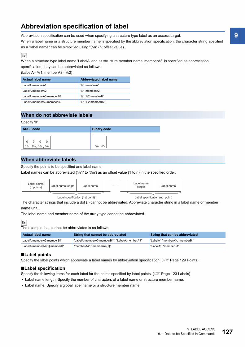
9 LABEL ACCESS9.1 Data to be Specified in Commands 127
9Abbreviation specification of labelAbbreviation specification can be used when specifying a structure type label as an access target.
When a label name or a structure member name is specified by the abbreviation specification, the character string specified
as a "label name" can be simplified using "%n" (n: offset value).
Ex.
When a structure type label name 'LabelA' and its structure member name 'memberA3' is specified as abbreviation
specification, they can be abbreviated as follows.
(LabelA= %1, memberA3= %2)
When do not abbreviate labelsSpecify '0'.
When abbreviate labelsSpecify the points to be specified and label name.
Label names can be abbreviated ('%1' to '%n') as an offset value (1 to n) in the specified order.
The character strings that include a dot (.) cannot be abbreviated. Abbreviate character string in a label name or member
name unit.
The label name and member name of the array type cannot be abbreviated.
Ex.
The example that cannot be abbreviated is as follows:
■Label pointsSpecify the label points which abbreviate a label names by abbreviation specification. (Page 129 Points)
■Label specificationSpecify the following items for each label for the points specified by label points. (Page 123 Labels)
• Label name length: Specify the number of characters of a label name or structure member name.
• Label name: Specify a global label name or a structure member name.
Actual label name Abbreviated label name
LabelA.memberA1 %1.memberA1
LabelA.memberA2 %1.memberA2
LabelA.memberA3.memberB1 %1.%2.memberB1
LabelA.memberA3.memberB2 %1.%2.memberB2
ASCII code Binary code
Actual label name String that cannot be abbreviated String that can be abbreviated
LabelA.memberA3.memberB1 "LabelA.memberA3.memberB1", "LabelA.memberA3" 'LabelA', 'memberA3', 'memberB1'
LabelA.memberA4[1].memberB1 "memberA4", "memberA4[1]" "LabelA", "memberB1"
030H
030H
030H
030H 00H 00H
Label points (n points) Label name length Label name
Label name length Label name
Label specification (1st point) Label specification (nth point)

1289 LABEL ACCESS9.1 Data to be Specified in Commands
Ex.
When a structure type label name 'LabelA' and its structure member name 'memberA3' is specified as abbreviation
specification
(1) LabelA
(2) memberA3
■Data communication in ASCII code
In the figure (1) and (2), set the value of "ASCII code" indicated in the table of "Value of code corresponds to character" of
each label name.
■Data communication in binary code
In the figure (1) and (2), set the value of "Binary code" indicated in the table of "Value of code corresponds to character" of
each label name.
Item Value of code corresponds to character
Label name L a b e l A
UTF-16 004C 0061 0062 0065 006C 0041
ASCII code 30303443 30303631 30303632 30303635 30303643 30303431
Binary code 4C00 6100 6200 6500 6C00 4100
Item Value of code corresponds to character
Label name m e m b e r A 3
UTF-16 006D 0065 006D 0062 0065 0072 0041 0033
ASCII code 30303644 30303635 30303644 30303632 30303635 30303732 30303431 30303333
Binary code 6D00 6500 6D00 6200 6500 7200 4100 3300
30H 30H 30H 36H30H 30H 30H 32H 30H 30H 30H 38H
0 0 600 0 20 0 0 80(1) (2)
Label points Label name length Label name Label name length Label name
Label specification (1st point) Label specification (2nd point)
02H 00H 06H 00H 08H 00H
(1) (2)
Label points Label name length Label name Label name length Label name
Label specification (1st point) Label specification (2nd point)
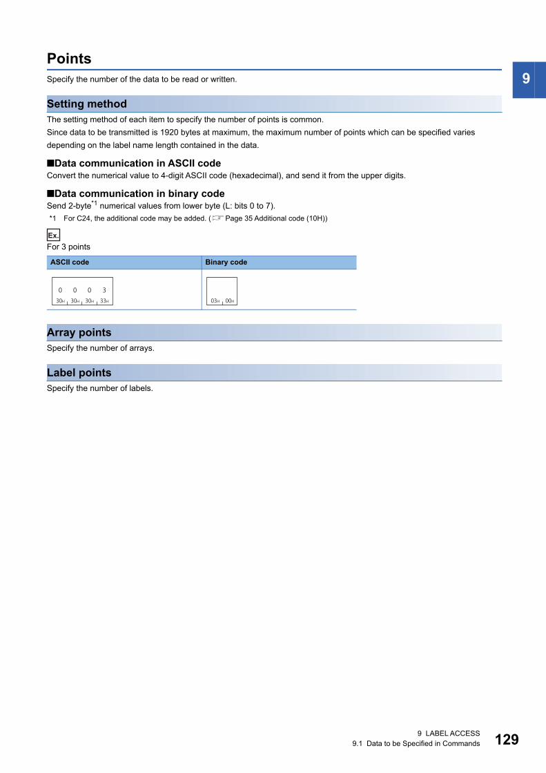
9 LABEL ACCESS9.1 Data to be Specified in Commands 129
9PointsSpecify the number of the data to be read or written.
Setting methodThe setting method of each item to specify the number of points is common.
Since data to be transmitted is 1920 bytes at maximum, the maximum number of points which can be specified varies
depending on the label name length contained in the data.
■Data communication in ASCII codeConvert the numerical value to 4-digit ASCII code (hexadecimal), and send it from the upper digits.
■Data communication in binary codeSend 2-byte*1 numerical values from lower byte (L: bits 0 to 7).
*1 For C24, the additional code may be added. (Page 35 Additional code (10H))
Ex.
For 3 points
Array pointsSpecify the number of arrays.
Label pointsSpecify the number of labels.
ASCII code Binary code
030H
030H
030H
333H 03H 00H

1309 LABEL ACCESS9.1 Data to be Specified in Commands
Data type IDThe data type of the read label is stored.
When writing data, the data type ID is not specified. The specified Follow the data type of the specified label.
The value of data type ID of each data type is shown below.
For an array type label and a structure type label, the data type of the element from which value is read is stored.
Setting method
■Data communication in ASCII codeConvert the numerical value to 2-digit ASCII code (hexadecimal), and send it from the upper digits.
■Data communication in binary codeSend a 1-byte numerical value.
Ex.
Double Word [Signed]
Data type Data type ID (decimal)
Setting value (hexadecimal)
Bit 1 01H
Word [Unsigned]/Bit String [16-bit] 2 02H
Double Word [Unsigned]/Bit String [32-bit] 3 03H
Word [Signed] 4 04H
Double Word [Signed] 5 05H
FLOAT [Single Precision] 6 06H
FLOAT [Double Precision] 7 07H
Time 8 08H
String 9 09H
String[Unicode] 10 0AH
Pointer Cannot be specified.
Timer
Counter
Retentive timer
Contact
Coil
1 01H
Current value 2 02H
Long timer
Long counter
Long retentive timer
Contact
Coil
1 01H
Current value 3 03H
ASCII code Binary code
030H
535H 05H
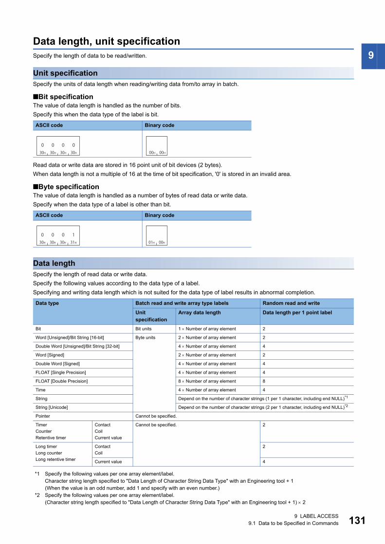
9 LABEL ACCESS9.1 Data to be Specified in Commands 131
9Data length, unit specificationSpecify the length of data to be read/written.
Unit specificationSpecify the units of data length when reading/writing data from/to array in batch.
■Bit specificationThe value of data length is handled as the number of bits.
Specify this when the data type of the label is bit.
Read data or write data are stored in 16 point unit of bit devices (2 bytes).
When data length is not a multiple of 16 at the time of bit specification, '0' is stored in an invalid area.
■Byte specificationThe value of data length is handled as a number of bytes of read data or write data.
Specify when the data type of a label is other than bit.
Data lengthSpecify the length of read data or write data.
Specify the following values according to the data type of a label.
Specifying and writing data length which is not suited for the data type of label results in abnormal completion.
*1 Specify the following values per one array element/label.Character string length specified to "Data Length of Character String Data Type" with an Engineering tool + 1(When the value is an odd number, add 1 and specify with an even number.)
*2 Specify the following values per one array element/label.(Character string length specified to "Data Length of Character String Data Type" with an Engineering tool + 1) 2
ASCII code Binary code
ASCII code Binary code
Data type Batch read and write array type labels Random read and write
Unit specification
Array data length Data length per 1 point label
Bit Bit units 1 Number of array element 2
Word [Unsigned]/Bit String [16-bit] Byte units 2 Number of array element 2
Double Word [Unsigned]/Bit String [32-bit] 4 Number of array element 4
Word [Signed] 2 Number of array element 2
Double Word [Signed] 4 Number of array element 4
FLOAT [Single Precision] 4 Number of array element 4
FLOAT [Double Precision] 8 Number of array element 8
Time 4 Number of array element 4
String Depend on the number of character strings (1 per 1 character, including end NULL)*1
String [Unicode] Depend on the number of character strings (2 per 1 character, including end NULL)*2
Pointer Cannot be specified.
Timer
Counter
Retentive timer
Contact
Coil
Current value
Cannot be specified. 2
Long timer
Long counter
Long retentive timer
Contact
Coil
2
Current value 4
030H
030H
030H
030H 00H 00H
030H
030H
030H
131H 01H 00H

1329 LABEL ACCESS9.1 Data to be Specified in Commands
■Data communication in ASCII codeConvert the numerical value to 4-digit ASCII code (hexadecimal), and send it from the upper digits.
■Data communication in binary codeSend 2-byte*1 numerical values from lower byte (L: bits 0 to 7).
*1 For C24, the additional code may be added. (Page 35 Additional code (10H))
Setting example
■Batch read and write of arrayFor the bit specification, specify the number of bits to be accessed.
• Unit specification: Bit
• Label: Bit type 3 points
• Array data length: 1 bit Number of array element (3) = 3 bits
For byte specification, specify the data length of the label to be accessed in byte unit.
• Unit specification: Byte
• Label: Word type 5 points
• Array data length: 2 bytes (5) = 10 bytes
■Random read and writeFor bit type, data length will be 2 (fixed value).
• Label: Bit type 1 point
• Data length: 2 (fixed)
The character string type [Unicode] will be 2 bytes per one character of UTF-16 code.
• Label: Character string type [Unicode] one point
• "Data Length of Character String Data Type" of an Engineering tool: 32
• Data length: Number of characters (32 + 1) Data length per one character string (2) = 66 (42H)
ASCII code Binary code
ASCII code Binary code
ASCII code Binary code
ASCII code Binary code
030H
030H
030H
333H 03H 00H
030H
030H
030H
A3AH 0AH 00H
030H
030H
030H
232H 02H 00H
030H
030H 34H
232H
442H 00H

9 LABEL ACCESS9.1 Data to be Specified in Commands 133
9Read data, write dataThe read data is stored for reading, and the data to be written is stored for writing.
Data is stored with variable length. The length of data is specified by "Data length." (Page 131 Data length)
The storing method of data is same as that of reading or writing data in word units (bit device in 16-points). (Page 72
Read data, write data)
For bit type labelsRead data and write data are handled in 16-point units, but '0' is stored in data other than label points to be accessed.
Ex.
For bit type label 6 points
For character string type labelsStore NULL at the end of the valid character string. The data after NULL of the read data will be undefined value.
Ex.
For read data of 1-point character string type (ASCII code) label
• Label character string: 'ABCD' (4 characters)
• "Data Length of Character String Data Type" of an Engineering tool: 32
• Data length: Number of characters (32 + 1) Data length per one character string (1) = 34 (22H)
When communicating ASCII code character string data in ASCII code, data is rearranged every two
characters and stored.
Item Character string type of ASCII code Character string type of Unicode
Number of character strings of label Odd Even number
NULL code to be stored to the end NULL (00H) NULL (00H)2 NULL (0000H)
Data length of array element/label per
one point
Character string specified to "Data
Length of Character String Data
Type" + 1
Character string specified to "Data
Length of Character String Data
Type" + 2
(Character string specified to "Data
Length of Character String Data
Type" + 1)2
ASCII code Binary code
Fixed to 0 Access targetbit data
0 101011000000000b0b15
("Data Length of String Data Type"(32)+2)×2 bytes
AB CD NULL NULL
4 2 4 1 4 34 4 0 0 0 0 …34H 32H 34H 32H 34H 34H 34H 33H 30H 30H 30H 30H
"Data Length of String Data Type"(32)+2 bytes
A B C41H 42H 43H
D44H
NULL00H 00H
NULL …
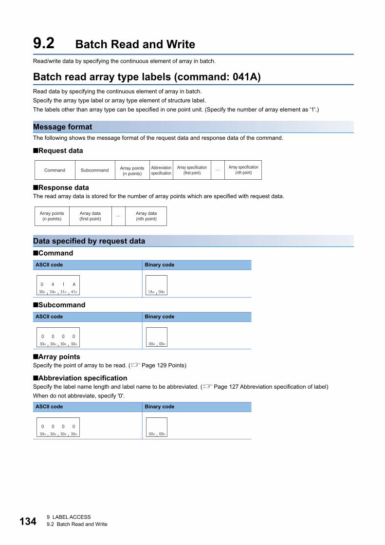
1349 LABEL ACCESS9.2 Batch Read and Write
9.2 Batch Read and WriteRead/write data by specifying the continuous element of array in batch.
Batch read array type labels (command: 041A) Read data by specifying the continuous element of array in batch.
Specify the array type label or array type element of structure label.
The labels other than array type can be specified in one point unit. (Specify the number of array element as '1'.)
Message formatThe following shows the message format of the request data and response data of the command.
■Request data
■Response dataThe read array data is stored for the number of array points which are specified with request data.
Data specified by request data
■Command
■Subcommand
■Array pointsSpecify the point of array to be read. (Page 129 Points)
■Abbreviation specificationSpecify the label name length and label name to be abbreviated. (Page 127 Abbreviation specification of label)
When do not abbreviate, specify '0'.
ASCII code Binary code
ASCII code Binary code
ASCII code Binary code
Command Subcommand Array points (n points)
Abbreviation specification
Array specification (first point)
Array specification (nth point)
Array points (n points)
Array data (first point)
Array data (nth point)
030H
434H
131H
A41H 1AH 04H
030H
030H
030H
030H 00H 00H
030H
030H
030H
030H 00H 00H

9 LABEL ACCESS9.2 Batch Read and Write 135
9
■Array specificationSpecify the details of arrays for number of arrays specified to array points.
Specify the following items for each array.
• Label name length, label name: Specify the label name and label length of a global label. (Page 123 Labels)
• Unit specification: For the bit type labels, specify the unit specification in bit units (0). As for other than bit type label, specify
the unit specification in byte units (1).
• Array data length: Specify the data size of array in the unit specified with "Unit specification." (Page 131 Data length,
unit specification)
• Fixed value: Fixed to '0'
Data stored in response data
■Array pointsThe same data as request data are stored.
■Array dataThe read array data is stored for number of arrays which are specified with array point.
The following items are stored for each array.
• Data type ID: The data type of the label name is stored with the defined ID. (Page 130 Data type ID)
• Unit specification: For the bit type labels, specify the unit specification in bit units (0). As for other than bit type label, specify
the unit specification in byte units (1).
• Array data length: Specify the data size of array in the unit specified with "Unit specification." (Page 131 Data length,
unit specification)
• Read data: The value of the read label is stored. (Page 133 Read data, write data)
When unit specification is bit specification, read data are stored in 16-bit (2-byte) units.
ASCII code Binary code
Label name length Label nameUnit
specificationFixed values
Array data length
Array specification (Array one point)
030H
030H 00H
Data type ID Array data length Read data
Array data (Array one point)
Unit specification

1369 LABEL ACCESS9.2 Batch Read and Write
Communication example (Bit specification)For one-dimensional array type label 'Lbl', read 2-bit data from Lbl [2].
The value of the read label is as follows:
■Data communication in ASCII code(Request data)
In the figure (1), set the value of "ASCII code" indicated in the following table.
(1) Lbl[2]
(Response data)
■Data communication in binary code(Request data)
(Response data)
Item Value of code corresponds to character
Label name L b l [ 2 ]
UTF-16 004C 0062 006C 005B 0032 005D
ASCII code 30303443 30303632 30303643 30303542 30303332 30303544
Fixed to 0 Access target data
0 0 0 0 0 0 0 0 0 0 0 0 0 0 1 0b15 b0
030H
434H
131H
A41H 30H 30H 30H 36H
030H
030H
030H
030H
030H
030H
030H
131H
030H
030H
030H
030H
0 0 0 630H 30H 30H 30H 30H 30H 30H 32H
0 0 0 0 0 0 0 2(1)
Subcommand Array points Abbreviation specification Label name length Label name Unit specification Array data length(Fixed value)
Array specification (Array one point)
30H 30H 30H 32H030H
030H
030H
131H
0 0 0 230H 31H 30H 30H 30H 32H0 1 0 0 0 2
Data type ID
Unit specification
Read data
Array points Array data length
Array data (Array one point)
1AH 04H 00H 00H 01H 00H 00H 00H 06H 00H 4CH 00H 62H 00H 6CH 00H 5BH 00H 32H 00H
L b l [ 25DH 00H 00H 00H
]02H 00H
(Fixed value)
SubcommandArray points
Abbreviation specification
Label name length
Unit specification
Array data lengthLabel name
Array specification (Array one point)
01H 00H 01H 00H 02H 00H 02H 00H
Data type IDUnit
specificationArray data
lengthRead data
Array points
Array data (Array one point)

9 LABEL ACCESS9.2 Batch Read and Write 137
9Communication example (Byte specification)For one-dimensional array type label 'Lbl', read 5-word data from Lbl [2].
■Data communication in ASCII code(Request data)
In the figure (1), set the value of "ASCII code" indicated in the following table.
(1) Lbl[2]
(Response data)
■Data communication in binary code(Request data)
(Response data)
Item Value of code corresponds to character
Label name L b l [ 2 ]
UTF-16 004C 0062 006C 005B 0032 005D
ASCII code 30303443 30303632 30303643 30303542 30303332 30303544
030H
434H
131H
A41H 30H 30H 30H 36H
030H
030H
030H
030H
030H
030H
030H
131H
030H
030H
030H
030H
0 0 0 630H 31H 30H 30H 30H 30H 30H 41H0 1 0 0 0 0 0 A(1)
Subcommand Array points Abbreviation specification Label name length Label name Unit specification (Fixed value) Array data length
Array specification (Array one point)
30H 30H 30H 31H 30H 33H 30H 31H 30H 30H 30H 41H 30H 30H 34H 34H 30H 30H 36H 31H 30H 30H 37H 34H 30H 30H 36H 31H 30H 30H 33H 31H
0 0 0 1 0 2 0 1 0 0 0 A 0 0 4 4 0 0 6 1 0 0 7 4 0 0 6 1 0 0 3 1
Data type ID
Unit specificationArray points Array data length Read data
Array data (Array one point)
1AH 04H 00H 00H 01H 00H 00H 00H 06H 00H 4CH 00H 62H 00H 6CH 00H 5BH 00H 32H 00H
L b l [ 25DH 00H 01H 00H
]0AH 00H
(Fixed value)
SubcommandArray points
Abbreviation specification
Label name length
Unit specification
Array data lengthLabel name
Array specification (Array one point)
01H 00H 02H 01H 0AH 00H 44H 00H 61H 00H 74H 00H 61H 00H 31H 00H
Unit specification
Array points
Data type ID
Array data length Read data
Array data (Array one point)

1389 LABEL ACCESS9.2 Batch Read and Write
Communication example (Abbreviate with structure type array) Read the following data from the structure label 'Typ1', which has the array type element.
• 8 bytes from Typ1.led[2]
• 4 bytes from Typ1.No[1]
The notation of each label when using abbreviation specification (Typ1= %1) is as follows.
(1)Typ1
(2)Typ1.led[2]
(3)Typ1.No[1]
Item Value of code corresponds to character
Label name T y p 1
UTF-16 0054 0079 0070 0031
ASCII code 30303534 30303739 30303730 30303331
Binary code 5400 7900 7000 3100
Item Value of code corresponds to character
Abbreviated notation % 1 . l e d [ 2 ]
UTF-16 0025 0031 002E 006C 0065 0064 005B 0032 005D
ASCII code 30303235 30303331 30303245 30303643 30303635 30303634 30303542 30303332 30303544
Binary code 2500 3100 2E00 6C00 6500 6400 5B00 3200 5D00
Item Value of code corresponds to character
Abbreviated notation % 1 . N o [ 1 ]
UTF-16 0025 0031 002E 004E 006F 005B 0031 005D
ASCII code 30303235 30303331 30303245 30303445 30303646 30303542 30303331 30303544
Binary code 2500 3100 2E00 4E00 6F00 5B00 3100 5D00

9 LABEL ACCESS9.2 Batch Read and Write 139
9
■Data communication in ASCII code(Request data)
In the figure (1) to (3), set the value of "ASCII code" indicated in the table of "Value of code corresponds to character" of each
label.
(Response data)
■Data communication in binary code(Request data)
In the figure (1) to (3), set the value of "Binary code" indicated in the table of "Value of code corresponds to character" of each
label.
(Response data)
30H 34H 31H 41H 30H 30H 30H 30H 30H 30H 30H 32H 30H 30H 30H 31H
0000000A140 02 00 1
30H 31H 30H 30H 30H 30H 30H 34H
40000010
30H 30H 30H 34H
(1)4000
30H 30H 30H 39H
(2)
(3)
900030H 31H 30H 30H
001030H 30H 30H 38H
8000
30H 30H 30H 38H
8000
Subcommand Array points Number of abbreviated points Label name length Label name
Abbreviation specification
Unit specification (Fixed value) Array data lengthLabel name length Label name
Label name length Label name Unit specification (Fixed value) Array data length
30H 30H 30H 32H 30H 32H 30H 31H 30H 30H 30H 38H 30H 30H 33H 31H 30H 30H 33H 32H 30H 30H 33H 33H 30H 30H 33H 34H
0 0 0 2 0 2 0 1 0 0 0 8 0 0 3 1 0 0 3 2 0 0 3 3 0 0 3 4
30H 33H 30H 31H 30H 30H 30H 34H 30H 30H 33H 30H 30H 30H 33H 31H
0 3 0 1 0 0 0 4 0 0 3 0 0 0 3 1
Array points Data type ID Unit specification Array data length Read data
Read data of Typ1.led
Data type ID Unit specification Array data length Read data
Read data of Typ1.No
1AH 04H 00H 00H 02H 00H 01H 00H 04H 00H
(1)
09H 00H 01H 00H 08H 00H 0BH 00H 01H 00H 04H 00H
(2) (3)
SubcommandArray points
Number of abbreviated points
Label name length Label name
Abbreviation specification
(Fixed value) (Fixed value)Label name
lengthUnit specification
Array data length
Label name length
Unit specification
Array data lengthLabel name Label name
02H 00H 03H 01H 08H 00H 31H 00H 32H 00H 33H 00H 34H 00H 03H 01H 04H 00H 30H 00H 31H 00H
Unit specification Unit specification
Array points
Array data length
Array data length
Data type ID
Data type IDRead data Read data
Read data of Typ1.led Read data of Typ1.No

1409 LABEL ACCESS9.2 Batch Read and Write
Batch write array type labels (command: 141A)Write the values in batch with specifying the consecutive array elements.
Specify the array type labels or array type elements of structure type labels.
The labels other than array type can be specified in one point unit. (Specify the number of array element as '1'.)
Message formatThe following shows the message format of the request data and response data of the command.
■Request data
■Response dataThere is no response data for this command.
Data specified by request data
■Command
■Subcommand
■Array pointsSpecify the point of array to be written. (Page 129 Points)
■Abbreviation specificationSpecify the label name length and label name to be abbreviated. (Page 127 Abbreviation specification of label)
When do not abbreviate, specify '0'.
■Array specificationSpecify the details of arrays for number of arrays specified to array points.
Specify the following items for each array.
• Label name length, label name: Specify the label name and label length of a global label. (Page 123 Labels)
• Unit specification: For the bit type labels, specify the unit specification in bit units (0). As for other than bit type label, specify
the unit specification in byte units (1).
• Array data length: Specify the data size of array in the unit specified by "Unit specification." (Page 131 Data length, unit
specification)
• Write data: Specify the value to be written. (Page 133 Read data, write data)
ASCII code Binary code
ASCII code Binary code
ASCII code Binary code
Command Subcommand Array points (n points)
Abbreviation specification
Array specification (first point)
Array specification (nth point)
131H
434H
131H
A41H 1AH 14H
030H
030H
030H
030H 00H 00H
030H
030H
030H
030H 00H 00H
Label name length Label nameUnit
specificationFixed values Array data length Write data
Array specification (Array one point)

9 LABEL ACCESS9.2 Batch Read and Write 141
9
• Fixed value: '0'.
Communication example (Bit specification)For one-dimensional array type label 'Lbl', write 2-bit data from Lbl [2].
The value of the label to be written is as follows:
■Data communication in ASCII code(Request data)
In the figure (1), set the value of "ASCII code" indicated in the following table.
(1) Lbl[2]
■Data communication in binary code(Request data)
ASCII code Binary code
Item Value of code corresponds to character
Label name L b l [ 2 ]
UTF-16 004C 0062 006C 005B 0032 005D
ASCII code 30303443 30303632 30303643 30303542 30303332 30303544
030H
030H 00H
Fixed to 0 Access target data
0 0 0 0 0 0 0 0 0 0 0 0 0 0 1 0b15 b0
30H 30H 30H 32H0 0 0 2
131H
434H
131H
A41H
30H 30H 30H 36H
030H
030H
030H
030H
030H
030H
030H
131H
030H
030H
030H
030H
0 0 0 630H 30H 30H 30H0 0 0 0(1)
30H 30H 30H 32H0 0 0 2
Subcommand Array points Abbreviation specification
Label name length Label name Unit specification (Fixed value) Array data length Write data
Array specification (Array one point)
1AH 14H 00H 00H 01H 00H 00H 00H 06H 00H 4CH 00H 62H 00H 6CH 00H 5BH 00H 32H 00H
L b l [ 25DH 00H 00H 00H
]02H 00H 02H 00H
(Fixed value)
Unit specification
Array data lengthSubcommand
Array points
Abbreviation specification
Label name length
Write dataLabel name
Array specification (Array one point)
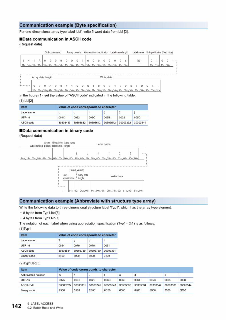
1429 LABEL ACCESS9.2 Batch Read and Write
Communication example (Byte specification)For one-dimensional array type label 'Lbl', write 5-word data from Lbl [2].
■Data communication in ASCII code(Request data)
In the figure (1), set the value of "ASCII code" indicated in the following table.
(1) Lbl[2]
■Data communication in binary code(Request data)
Communication example (Abbreviate with structure type array)Write the following data to three-dimensional structure label 'Typ1', which has the array type element.
• 8 bytes from Typ1.led[5]
• 4 bytes from Typ1.No[7]
The notation of each label when using abbreviation specification (Typ1= %1) is as follows.
(1)Typ1
(2)Typ1.led[5]
Item Value of code corresponds to character
Label name L b l [ 2 ]
UTF-16 004C 0062 006C 005B 0032 005D
ASCII code 30303443 30303632 30303643 30303542 30303332 30303544
Item Value of code corresponds to character
Label name T y p 1
UTF-16 0054 0079 0070 0031
ASCII code 30303534 30303739 30303730 30303331
Binary code 5400 7900 7000 3100
Item Value of code corresponds to character
Abbreviated notation % 1 . l e d [ 5 ]
UTF-16 0025 0031 002E 006C 0065 0064 005B 0035 005D
ASCII code 30303235 30303331 30303245 30303643 30303635 30303634 30303542 30303335 30303544
Binary code 2500 3100 2E00 6C00 6500 6400 5B00 3500 5D00
131H
434H
131H
A41H
030H
030H
030H
030H
030H
030H
030H
131H
030H
030H
030H
030H 30H 31H 30H 30H
30H 30H 30H 41H
0 1
0 0 0 A 0 0 4 4 0 0 6 1 0 0 7 4 0 0 6 1 0 0 3 130H 30H 34H 34H 30H 30H 36H 31H 30H 30H 37H 34H 30H 30H 36H 31H 30H 30H 33H 31H
30H 30H 30H 36H
0 0 0 6 0 0(1)
Subcommand Array points Abbreviation specification Label name length Label name Unit specification (Fixed value)
Array data length Write data
1AH 14H 00H 00H 01H 00H 00H 00H 06H 00H 4CH 00H 62H 00H 6CH 00H 5BH 00H 32H 00H 5DH 00H
L b l [ 2 ]
01H 00H 0AH 00H 44H 00H 61H 00H 74H 00H 61H 00H 31H 00H
SubcommandArray points
Abbreviation specification
Label name length Label name
(Fixed value)
Unit specification
Array data length
Write data
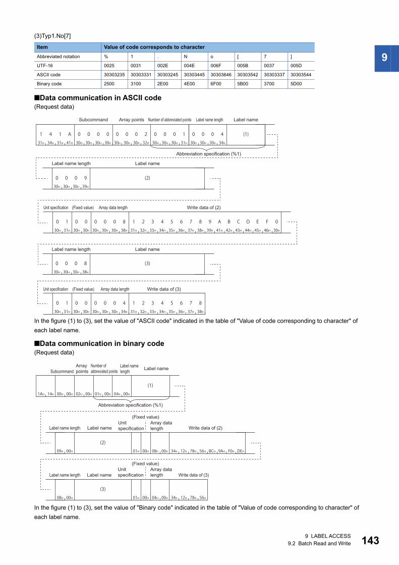
9 LABEL ACCESS9.2 Batch Read and Write 143
9
(3)Typ1.No[7]
■Data communication in ASCII code(Request data)
In the figure (1) to (3), set the value of "ASCII code" indicated in the table of "Value of code corresponding to character" of
each label name.
■Data communication in binary code(Request data)
In the figure (1) to (3), set the value of "Binary code" indicated in the table of "Value of code corresponding to character" of
each label name.
Item Value of code corresponds to character
Abbreviated notation % 1 . N o [ 7 ]
UTF-16 0025 0031 002E 004E 006F 005B 0037 005D
ASCII code 30303235 30303331 30303245 30303445 30303646 30303542 30303337 30303544
Binary code 2500 3100 2E00 4E00 6F00 5B00 3700 5D00
31H 34H 31H 41H 30H 30H 30H 30H 30H 30H 30H 32H 30H 30H 30H 31H
0000000A141 02 00 1
30H 31H 30H 30H 30H 30H 30H 34H 31H 32H 33H 34H 35H 36H 37H 38H
40000010
30H 30H 30H 34H
(1)4000
30H 30H 30H 39H
(2)9000
30H 31H 30H 30H
001030H 30H 30H 38H
8000 4321 8765
4321 8765
CBA9 0FED31H 32H 33H 34H 35H 36H 37H 38H 39H 41H 42H 43H 44H 45H 46H 30H
30H 30H 30H 38H
8000 (3)
Subcommand Array points Number of abbreviated points Label name length Label name
Abbreviation specification (%1)
Label name length Label name
Unit specification (Fixed value) Array data length Write data of (2)
Label name length Label name
Unit specification (Fixed value) Array data length Write data of (3)
1AH 14H 00H 00H 02H 00H 01H 00H 04H 00H
(1)
09H 00H 01H 00H 78H 56H BCH 9AH F0H DEH08H 00H 34H 12H
(2)
08H 00H 34H 12H 78H 56H01H 00H 04H 00H
(3)
SubcommandArray points
Number of abbreviated points
Label name length Label name
Abbreviation specification (%1)
(Fixed value)Unit specification
Array data lengthLabel name length Label name Write data of (2)
(Fixed value)Unit specification
Array data lengthLabel name length Label name Write data of (3)

1449 LABEL ACCESS9.3 Random Read and Write
9.3 Random Read and WriteSpecify a label and read/write value in one point unit. When reading and writing data in batch by specifying continuous
elements of array, use batch read and write command. (Page 134 Batch Read and Write)
Random read labels (command: 041C) Read value in one point units by specifying multiple labels.
Message formatThe following shows the message format of the request data and response data of the command.
■Request data
■Response dataThe data of read label is stored for the number of label points specified with request data.
Data specified by request data
■Command
■Subcommand
■Label pointsSpecify the point of label to read. (Page 129 Points)
■Abbreviation specificationSpecify the label name length and label name to be abbreviated. (Page 127 Abbreviation specification of label)
When do not abbreviate, specify '0'.
■Label specificationSpecify the label name and label length of global label for the specified number of label points. (Page 123 Labels)
For a structure type label or array type label, specify the data of each element.
ASCII code Binary code
ASCII code Binary code
ASCII code Binary code
Command SubcommandLabel points
(n points)Abbreviation specification
Label specification (1st point)
Label specification (nth point)
Label points (n points)
Label data (1st point)
Label data (nth point)
030H
434H
131H
C43H 1CH 04H
030H
030H
030H
030H 00H 00H
030H
030H
030H
030H 00H 00H

9 LABEL ACCESS9.3 Random Read and Write 145
9Data stored in response data
■Label pointsThe same data as request data are stored.
■Label dataThe data of read label for the specified number of label points is stored.
The following items are stored for each label.
• Data type ID: The data type of label name is stored with the defined ID. (Page 130 Data type ID)
• Read data length: Specify the read data size in byte units. (Page 131 Data length, unit specification)
• Read data: The value of read label is stored in the format of "Data type ID". (Page 133 Read data, write data)
• Spare data: The 2-byte of system data for data communication in ASCII code, and the 1-byte*1 of system data for data
communication in binary code is stored.
*1 For C24, the additional code may be added. (Page 35 Additional code (10H))
Communication exampleRead data from three labels.
• Lbl1 (bit type) = 1 (ON)
• Lbl2.Lbl[2] (word type array element of structure label) = 0031H
• Lbl3 (word type) =0001H
The notation of each label when using abbreviation specification (Lbl2 = %1) is as follows.
(1) Lbl2 (abbreviation specification)
(2) Lbl1
(3) Lbl2.Lbl[2]
(4) Lbl3
Item Value of code corresponds to character
Label name L b l 2
UTF-16 004C 0062 006C 0032
ASCII code 30303443 30303632 30303643 30303332
Binary code 4C00 6200 6C00 3200
Item Value of code corresponds to character
Label name L b l 1
UTF-16 004C 0062 006C 0031
ASCII code 30303443 30303632 30303643 30303331
Binary code 4C00 6200 6C00 3100
Item Value of code corresponds to character
Abbreviated notation % 1 . L b l [ 2 ]
UTF-16 0025 0031 002E 004C 0062 006C 005B 0032 005D
ASCII code 30303235 30303331 30303245 30303443 30303632 30303643 30303542 30303332 30303544
Binary code 2500 3100 2E00 4C00 6200 6C00 5B00 3200 5D00
Item Value of code corresponds to character
Label name L b l 3
UTF-16 004C 0062 006C 0033
ASCII code 30303443 30303632 30303643 30303333
Binary code 4C00 6200 6C00 3300
Spare data
Read data length Read dataData type ID
Label data (1 point)

1469 LABEL ACCESS9.3 Random Read and Write
■Data communication in ASCII code(Request data)
In the figure (1) to (4), set the value of "ASCII code" indicated in the table of "Value of code corresponding to character" of
each label name.
(Response data)
■Data communication in binary code(Request data)
In the figure (1) to (4), set the value of "Binary code" indicated in the table of "Value of code corresponding to character" of
each label name.
(Response data)
30H 30H 30H 34H
(2)400030H 30H 30H 39H
(3)9000
30H 34H 31H 43H 30H 30H 30H 30H 30H 30H 30H 33H 30H 30H 30H 31H
0000000C140 03 00 130H 30H 30H 34H
(1)4000
30H 30H 30H 34H
(4)4000
Subcommand Label points Number of abbreviated points Label name length Label name
Label name length Label name Label name length Label name Label name length Label name
30H 30H 30H 33H 30H 31H 30H 30H 30H 30H 30H 32H 30H 30H 30H 31H
00000103000 02 00 1
30H 30H 30H 32H
200030H 30H 33H 31H
300 130H 32H 30H 30H
002030H 30H 30H 32H
200030H 30H 30H 31H
000 130H 32H 30H 30H
0020
Data type ID
Spare data Read data length Read dataLabel points
Label data (1st point)
Data type ID
Spare data
Data type ID
Spare dataRead data length Read data Read data length Read data
Label data (2nd point) Label data (3rd point)
1CH 04H 00H 00H 03H 00H 01H 00H 04H 00H(1)
04H 00H(2)
09H 00H(3)
04H 00H(4)
SubcommandLabel points
Number of abbreviated points
Label name length Label name
Label name length
Label name length
Label name lengthLabel name Label name Label name
03H 00H 01H 00H 02H 00H 01H 00H 02H 00H 02H 00H 31H 00H 02H 00H 02H 00H 01H 00H
Data type ID Data type ID Data type ID
Label points
Spare data
Read data length
Read data
Spare data
Read data length
Read data
Spare data
Read data length
Read data
Label data (1st point) Label data (2nd point) Label data (3rd point)

9 LABEL ACCESS9.3 Random Read and Write 147
9Random write labels (command: 141B) Write value in one point units by specifying multiple labels.
Message formatThe following shows the message format of the request data and response data of the command.
■Request data
■Response dataThere is no response data for this command.
Data specified by request data
■Command
■Subcommand
■Label pointsSpecify the number of label points to be written. (Page 129 Points)
■Abbreviation specificationSpecify the label name length and label name to be abbreviated. (Page 123 Labels)
When do not abbreviate, specify '0'.
■Label specificationSpecify the label name and write data for the specified number of label points.
Specify the following items for each label.
• Label name length, label name: Specify the label name and label length of a global label. (Page 123 Labels)
• Write data length: Specify he read data size in byte unit. (Page 131 Data length, unit specification)
• Write data: Store the values of labels to be written. (Page 133 Read data, write data)
ASCII code Binary code
ASCII code Binary code
ASCII code Binary code
Command SubcommandLabel points
(n points)Abbreviation specification
Label specification (1st point)
Label specification (nth point)
131H
434H
131H
B42H 1BH 14H
030H
030H
030H
030H 00H 00H
030H
030H
030H
030H 00H 00H
Label name length Label name Write data length Write data
Label specification (1 point)

1489 LABEL ACCESS9.3 Random Read and Write
Communication exampleWrite data to three labels.
• Lbl1 (bit type) = 1 (ON)
• Lbl2.Lbl[2] (word type array element of structure label) = 0031H
• Lbl3 (word type) = 0001H
The notation of each label when using abbreviation specification (Lbl2 = %1) is as follows.
(1) Lbl2 (abbreviation specification)
(2) Lbl1
(3) Lbl2.Lbl[2]
(4) Lbl3
Item Value of code corresponds to character
Label name L b l 2
UTF-16 004C 0062 006C 0032
ASCII code 30303443 30303632 30303643 30303332
Binary code 4C00 6200 6C00 3200
Item Value of code corresponds to character
Label name L b l 1
UTF-16 004C 0062 006C 0031
ASCII code 30303443 30303632 30303643 30303331
Binary code 4C00 6200 6C00 3100
Item Value of code corresponds to character
Abbreviated notation % 1 . L b l [ 2 ]
UTF-16 0025 0031 002E 004C 0062 006C 005B 0032 005D
ASCII code 30303235 30303331 30303245 30303443 30303632 30303643 30303542 30303332 30303544
Binary code 2500 3100 2E00 4C00 6200 6C00 5B00 3200 5D00
Item Value of code corresponds to character
Label name L b l 3
UTF-16 004C 0062 006C 0033
ASCII code 30303443 30303632 30303643 30303333
Binary code 4C00 6200 6C00 3300

9 LABEL ACCESS9.3 Random Read and Write 149
9
■Data communication in ASCII code(Request data)
In the figure (1) to (4), set the value of "ASCII code" indicated in the table of "Value of code corresponding to character" of
each label name.
■Data communication in binary code(Request data)
In the figure (1) to (4), set the value of "Binary code" indicated in the table of "Value of code corresponding to character" of
each label name.
30H 30H 30H 34H
(2)4000
30H 30H 30H 39H
(3)9000
31H 34H 31H 42H 30H 30H 30H 30H 30H 30H 30H 33H 30H 30H 30H 31H
0000000B141 03 00 130H 30H 30H 34H
(1)4000
30H 30H 30H 34H
(4)4000
30H 30H 30H 32H
200030H 30H 30H 31H
1000
30H 30H 30H 32H
200030H 30H 33H 31H
1300
30H 30H 30H 32H
200030H 30H 30H 31H
1000
Subcommand Label points Number of abbreviated points Label name length Label name
Label name length Label name Write data length Write data
Label name length Label name Write data length Write data
Label name length Label name Write data length Write data
1BH 14H 00H 00H 03H 00H 01H 00H 04H 00H(1)
04H 00H(2)
09H 00H(3)
04H 00H(4)
02H 00H 01H 00H
02H 00H 31H 00H
02H 00H 01H 00H
Label points
Label name lengthSubcommand
Label name
Label name length
Write data length
Write data
Label name
Label name length
Write data length
Write data
Label name
Label name length
Write data length
Write data
Label name
Number of abbreviated points

15010 BUFFER MEMORY ACCESS10.1 Buffer Memory
10 BUFFER MEMORY ACCESS
This chapter explains the commands which read and write the buffer memory.
The buffer memory can be accessed with device access function using module access device (Un\G).
Page 440 Accessing module access devices
Page 65 DEVICE ACCESS
10.1 Buffer MemoryThis section explains the command which reads and writes data to the buffer memory of the supported device connected to
the external device.
The command can only be used for C24 (including multidrop connection station) and E71 connected to an
external device. It cannot be used via network.
This command is processed by C24/E71 connected to the CPU module without waiting for the END process.
Data to be specified in commandsThis section explains the contents and specification methods for data items which are set in each command related to the
access to the host station (supported device) buffer memory.
Start addressSpecify the start address of the buffer memory to be read/written.
■Data communication in ASCII codeConvert the numerical value to 8-digit (hexadecimal) ASCII code, and send it from the upper digits.
■Data communication in binary codeSend 4-byte numerical values from the lower byte (L: bits 0 to 7).
Ex.
When the head area address is 1E1H
ASCII code Binary code
30H 30H 30H 30H 30H 31H 45H 31H
0 0 00 0 1 1EE1H 01H 00H 00H

10 BUFFER MEMORY ACCESS10.1 Buffer Memory 151
10
Word lengthSpecify the word length of the buffer memory to be read/written.
■Data communication in ASCII codeConvert the numerical value to 4-digit ASCII code (hexadecimal), and send it from the upper digits.
■Data communication in binary codeSend 2-byte numerical values from lower byte (L: bits 0 to 7).
Ex.
For 5 words and 20 words
Read data, write dataThe read buffer memory value is stored for reading, and the data to be written is stored for writing.
This function reads/writes data in word unit.
■Data communication in ASCII codeConvert the numerical value to 4-digit ASCII code (hexadecimal), and send it from the upper digits.
■Data communication in binary codeSend 2-byte numerical values from lower byte (L: bits 0 to 7).
Ex.
When the data for one buffer memory address is 09C1H
Number of device points ASCII code Binary code
5 words
20 words
ASCII code Binary code
30H 30H 30H 35H
0 0 5005H 00H
30H 30H 31H 34H
0 0 4114H 00H
30H 39H 43H 31H
0 9 1CC1H 09H

15210 BUFFER MEMORY ACCESS10.1 Buffer Memory
Batch read (command: 0613)Read data from the buffer memory of the host station (supported device).
Message formatThe following shows the message format of the request data and response data of the command.
■Request data
■Response dataThe value read from the buffer memory is stored. The data order differs depending on the type of code, ASCII code or binary
code.
Page 151 Read data, write data
Data specified by request data
■Command
■Subcommand
■Start addressSpecify the buffer memory start address to be read. (Page 150 Start address)
■Word lengthSpecify the word length of the buffer memory to be read. (Page 151 Word length)
Specification range: 1H to 1E0H (480)
Specify the access range within the range of buffer memory.
(Start address + Word length -1) Buffer memory range
ASCII code Binary code
ASCII code Binary code
Command Subcommand Start address Word length
030H
636H
131H
333H 13H 06H
030H
030H
030H
030H 00H 00H

10 BUFFER MEMORY ACCESS10.1 Buffer Memory 153
10
Communication exampleRead the data of the buffer memory addresses from 78H to 81H (120 to 129).
■Data communication in ASCII code(Request data)
(Response data)
■Data communication in binary code(Request data)
(Response data)
0 6 1 330H 36H 31H 33H
0 0 030H 30H 30H
0 0 030H 30H 30H
0 0 030H 30H 30H
0 7 830H 37H 38H
0 0 030H 30H 30H
A41H
Start address Word length
0 5 0 030H 35H 30H 30H
0 9 C30H 39H 43H
131H
0 030H 30H
C 843H 38H
Read data 1 Read data 2 Read data 10
Values of address 78H=0500H
Values of address 79H=09C1H
Values of address 81H=00C8H
13H 06H 00H 00H 78H 00H 00H 00H 0AH 00H
Start address Word length
00H 05H C1H 09H C8H 00H
Read data 1
Read data 2
Read data 10
Values of address 78H=0500H
Values of address 79H=09C1H
Values of address 81H=00C8H

15410 BUFFER MEMORY ACCESS10.1 Buffer Memory
Batch write (command: 1613)Write data to the buffer memory of the host station (supported device).
Do not write any data in "System area" or "Write-protect area" in the buffer memory.
Writing data to the "System area" or "Write-protect area" may cause malfunction of the programmable
controller system.
Message formatThe following shows the message format of the request data and response data of the command.
■Request data
■Response dataThere is no response data for this command.
Data specified by request data
■Command
■Subcommand
■Start addressSpecify the buffer memory start address to be written. (Page 150 Start address)
■Word lengthSpecify the word length of the buffer memory to be written. (Page 151 Word length)
Specification range: 1H to 1E0H(480)
■Write dataSpecify the data to be written in the buffer memory. (Page 151 Read data, write data)
Specify the access range within the range of buffer memory.
(Start address + Word length -1) Buffer memory range
ASCII code Binary code
ASCII code Binary code
Command Subcommand Start address Word length Write data 1 Write data n
131H
636H
131H
333H 13H 16H
030H
030H
030H
030H 00H 00H

10 BUFFER MEMORY ACCESS10.1 Buffer Memory 155
10
Communication exampleWrite the value to buffer memory addresses from 2680H to 2683H (9856 to 9859).
■Data communication in ASCII code(Request data)
■Data communication in binary code(Request data)
1 6 1 331H 36H 31H 33H
0 0 030H 30H 30H
0 0 030H 30H 30H
0 0 230H 30H 32H
6 8 036H 38H 30H
0 0 030H 30H 30H
434H
2 0 032H 30H 30H
030H
0 0 030H 30H 30H
030H
Start address Word length Write data 1 Write data 4
Values of address 2680H=2000H
Values of address 2683H=0H
13H 16H 00H 00H 80H 26H 00H 00H 04H 00H 00H 20H 00H 00H
Write data 1
Write data 4Start address Word length
Values of address 2680H=2000H
Values of address 2683H=0H

15610 BUFFER MEMORY ACCESS10.2 Intelligent Function Module
10.2 Intelligent Function ModuleThe section explains the commands to read from/write to the buffer memory of an intelligent function module.
Accessible modulesThe following shows the accessible intelligent functional modules to buffer memory.
Accessing buffer memory using module access device (Un\G)The intelligent function modules, which can be accessed the module access device (Un\G), can be accessed by the device
access function.
Page 440 Accessing module access devices
Page 65 DEVICE ACCESS
Accessing buffer memory with calculating a start addressUse the command (0601, 1601) shown in this section to access the following devices.
Module Model Additional values when calculating start address
Load cell input module Q61LD 2000H
Loop control module Q62HLC 10000H
Analogdigital converter module Q62AD-DGH, Q64AD, Q64AD-GH, Q66AD-DG,
Q68AD-G, Q68ADV, Q68ADI
1008H
Digitalanalog converter module Q62DA, Q62DA-FG, Q62DAN, Q64DA, Q64DAN, Q66DA-G,
Q68DAV, Q68DAI, Q68DAVN, Q68DAIN
1008H
Analog input/output module Q64AD2DA 2000H
Temperature control module Q64TCTT, Q64TCRT, Q64TCTTBW, Q64TCRTBW 1000H
Temperature input module (function version B) Q64TD, Q64RD 2000H
Temperature input module (function version C) Q64TD, Q64TDV-GH, Q64RD, Q64RD-G 8000H
Channel isolated thermocouple input module Q68TD-G-H01, Q68TD-G-H02 1008H
Channel isolated RTD input module Q68RD3-G 1008H
ID Interface module QD35ID1, QD35ID2 4000H
Intelligent communication module QD51, QD51-R24 10000H
Channel isolated pulse input module QD60P8-G 2000H
High-speed counter module QD62, QD62E, QD62D 3CH
Multichannel high-speed counter module QD63P6 2000H
4Mpps capable high-speed counter module QD64D2 2000H
Positioning module QD70P4, QD70P8, QD70D4, QD70D8, QD72P3C3 5000H
QD75P1, QD75P2, QD75P4, QD75D1, QD75D2, QD75D4,
QD75M1, QD75M2, QD75M4, QD75MH1, QD75MH2, QD75MH4
10000H
High speed data logger module QD81DL96 10000H
CC-Link system master/local module QJ61BT11, QJ61BT11N 10000H
CC-Link/LT master module QJ61CL12 01B4H
Serial communication module QJ71C24N, QJ71C24N-R2, QJ71C24N-R4, QJ71C24, QJ71C24-R2 10000H
AS-i master module QJ71AS92 10000H
Ethernet interface module QJ71E71-100, QJ71E71-B5, QJ71E71-B2 10000H
FL-net (OPCN-2) interface module QJ71FL71-T, QJ71FL71-B2, QJ71FL71-B5,
QJ71FL71-T-F01, QJ71FL71-B2-F01, QJ71FL71-B5-F01
10000H
MODBUS interface module QJ71MB91, QJ71MT91 10000H
MES interface module QJ71MES96 10000H
Web server module QJ71WS96 10000H
PROFIBUS-DP Interface module QJ71PB92D 10000H
PROFIBUS-DP Master module QJ71PB92V 10000H
PROFIBUS-DP Slave module QJ71PB93D 10004H

10 BUFFER MEMORY ACCESS10.2 Intelligent Function Module 157
10
By using the command (0601, 1601), MELSEC-QnA series special function modules can be accessed.
When accessing buffer memory of MELSEC-A series special function modules, use the command of 1C/1E frame.
• 1C frame: Page 381 Read and write Buffer Memory of Special Function Module
• 1E frame: Page 430 Read and Write Buffer Memory of Special Function Module
Data to be specified in commandsThis section explains the contents and specification methods for data items which are set in each command related to the
access to the intelligent function module buffer memory.
Start addressSpecify the start address of the buffer memory to be read/written.
■Calculation methodTo access the buffer memory of the intelligent function module which consisted of word units by byte unit, specify a start
address calculated by byte unit.
Calculate the start address as follows:
Start address = (Buffer memory address 2) + Additional value of a module
For the arbitrary additional value of the module, refer to the following section.
Page 156 Accessing buffer memory with calculating a start address
Ex.
When specifying Q62DA buffer memory address 18H
(18H2) + 1008H = 30H + 1008H = 1038H
■Data communication in ASCII codeConvert the numerical value to 8-digit (hexadecimal) ASCII code, and send it from the upper digits.
■Data communication in binary codeSend 4-byte numerical values from the lower byte (L: bits 0 to 7).
Ex.
When the start address is 1038H
Module Model Additional values when calculating start address
CC-Link system master/local module AJ61QBT11, A1SJ61QBT11 2000H
Ethernet interface module AJ71QE71, AJ71QE71-B5, A1SJ71QE71-B2, A1SJ71QE71-B5 4000H
Serial communication module AJ71QC24, AJ71QC24-R2, AJ71QC24-4, AJ71QC24N, AJ71QC24N-R2,
AJ71QC24N-R4, A1SJ71QC24, A1SJ71QC24-R2, A1SJ71QC24N,
A1SJ71QC24N-R2
4000H
ASCII code Binary code
31H 30H 33H 38H30H 30H 30H 30H
0 0 00 1 0 8338H 10H 00H 00H

15810 BUFFER MEMORY ACCESS10.2 Intelligent Function Module
Number of bytesSpecify the number of bytes of the data to be read/written.
■Calculation methodThe buffer memory for intelligent function module consists of two bytes (one word) for one area. Calculate the number of
bytes by 2-byte per data for one buffer memory address.
Number of bytes = (Number of buffer memory address 2)
Ex.
When accessing the buffer memory address 160 to 161 (A0H to A1H)
(161- 160 + 1) 2 = 2 2 = 4 bytes
■Data communication in ASCII codeConvert the numerical value to 4-digit ASCII code (hexadecimal), and send it from the upper digits.
Use capitalized code for alphabetical letter.
■Data communication in binary codeSend 2-byte numerical values from lower byte (L: bits 0 to 7).
Ex.
For 20 bytes
Module numberSpecify the start input/output number of an intelligent function module to be accessed.
For the module number, specify the value obtained by dividing the start input/output number by 16 in 4 digits (hexadecimal).
■When the number of occupied slots are 2Specify the value obtained by adding 1 to the module number for the following modules.
■Data communication in ASCII codeConvert the numerical value to 4-digit ASCII code (hexadecimal), and send it from the upper digits.
Use capitalized code for alphabetical letter.
■Data communication in binary codeSend 2-byte numerical values from lower byte (L: bits 0 to 7).
Ex.
When accessing the positioning module whose start input/output number is 0080H
Number of device points ASCII code Binary code
20 words
Module type Model
Temperature control module Q64TCTTBW, Q64TCRTBW
Positioning module QD70D4, QD70D8
Module number ASCII code Binary code
For QD70P4:
0008H
For QD70D4 (occupied slots are 2):
0008H + 1 = 0009H
30H 30H 31H 34H
0 0 4114H 00H
30H 30H 30H 38H
0 0 8008H 00H
30H 30H 30H 39H
0 0 9009H 00H

10 BUFFER MEMORY ACCESS10.2 Intelligent Function Module 159
10
■Intelligent function module number of MELSECNET/H remote I/O stationIntelligent function module number of MELSECNET/H remote I/O station is the upper 2 digits of the last number represented
with 3-digit number of the following "Input/output signal based on the remote I/O station".
Specify this with "Input/output signal based on the remote I/O station" regardless of the contents of common parameters set in
the master station of MELSECNET/H remote I/O network.
Read data, write dataThe read buffer memory value is stored for reading, and the data to be written is stored for writing.
This function reads/writes data in byte unit.
■Data communication in ASCII codeHandle a word data for one buffer memory address as 2-byte data.
Convert the value to 2-digit (hexadecimal) ASCII code per one byte, and send it from the upper digit.
■Data communication in binary codeHandle a word data for one buffer memory address as 2-byte data.
Send 2-byte numerical values from lower byte (L: bits 0 to 7).
Ex.
When the data for one buffer memory address is 09C1H
When reading data from the following buffer memory addresses, 0H to 2H (additional value of the start address: 10000H)
ASCII code Binary code
Buffer memory Read 6 bytes from address 0H Read 4 bytes from address 1H
Address Stored data Start address
Read data (byte unit) Start address
Read data (byte unit)
Word unit Byte unit ASCII code Binary code ASCII code Binary code
0H 0003H 03H 10000H 30H, 33H 03H
00H 30H, 30H 00H
1H 0001H 01H 30H, 31H 01H 10002H 30H, 31H 01H
00H 30H, 30H 00H 30H, 30H 00H
2H 0012H 12H 31H, 32H 12H 31H, 32H 12H
00H 30H, 30H 00H 30H, 30H 00H
AJ72LP25
Intelligent function module No. "04H"
Input/output signalbased on the remote I/O station
Output module
Intelligentfunctionmodule
Output module
Power supplymodule
Output module
Output moduleRemote I/O station,
station 1
32 points 32 points 32 points16 points 16 points
Input/output signalby common parameters
Y00 to 1F
Y20 to 2F
X/Y30 to 4F
Y50 to 6F
Y70 to 8F
Y400 to 41F
Y420 to 42F
X/Y430 to 44F
Y450 to 46F
Y470 to 48F
43H 31H 30H 39H
C 1 90C1H 09H

16010 BUFFER MEMORY ACCESS10.2 Intelligent Function Module
Batch read (command: 0601)Read the data from the buffer memory of an intelligent function module.
Message formatThe following shows the message format of the request data and response data of the command.
■Request data
■Response dataThe value read from the buffer memory is stored.
Page 159 Read data, write data
Data specified by request data
■Command
■Subcommand
■Start addressSpecify the buffer memory start address to be read. (Page 157 Start address)
■Number of bytesSpecify the number of bytes of the buffer memory to be read. (Page 158 Number of bytes)
Specification range: 2H to 780H (1920)
■Module numberSpecify the intelligent function module to be read. (Page 158 Module number)
Specify the access range within the range of buffer memory.
ASCII code Binary code
ASCII code Binary code
Command Subcommand Start address Number of bytes
Module No.
030H
636H
030H
131H 01H 06H
030H
030H
030H
030H 00H 00H

10 BUFFER MEMORY ACCESS10.2 Intelligent Function Module 161
10
Communication exampleRead the data of the buffer memory addresses 1H to 2H of Q62DA whose input/output signal is from 30H to 4FH (module No.:
03H).
■Data communication in ASCII code(Request data)
(Response data)
■Data communication in binary code(Request data)
(Response data)
Buffer memory of Q62DA Data for command
Address Name Stored data (word unit) Read data (byte unit)
1H CH1 digital value 0001H 01H
00H
2H CH2 digital value 0012H 12H
00H
0 030H 30H
0 0 130H 30H 31H
0 0 A30H 30H 41H
0 0 030H 30H 30H
434H
0 0 030H 30H 30H
333H
0 6 030H 36H 30H
131H
0 0 030H 30H 30H
030H
Start address Number of bytes Module No.
30H0
31H1
30H030H0
31H1
32H2
30H0
30H0
Read data
Values of address 1H=0001H
Values of address 2H=0012H
00H 00H 04H 00H 03H 00H01H 06H 00H 00H 0AH 10H
Number of bytes
Module No.Start address
01H 00H 12H 00H
Read data
Values of address 1H=0001H
Values of address 2H=0012H

16210 BUFFER MEMORY ACCESS10.2 Intelligent Function Module
Batch write (command: 1601)Write data to the buffer memory of an intelligent function module.
Do not write any data in "System area" or "Write-protect area" in the buffer memory.
Writing data to the "System area" or "Write-protect area" may cause malfunction of the programmable
controller system.
Message formatThe following shows the message format of the request data and response data of the command.
■Request data
■Response dataThere is no response data for this command.
Data specified by request data
■Command
■Subcommand
■Start addressSpecify the buffer memory start address to be written. (Page 157 Start address)
■Number of bytesSpecify the number of bytes of the buffer memory to be written. (Page 158 Number of bytes)
Specification range: 2H to 780H (1920)
■Module numberSpecify the intelligent function module to be written. (Page 158 Module number)
■Write dataSpecify the data to be written in the buffer memory. (Page 159 Read data, write data)
Specify the access range within the range of buffer memory.
ASCII code Binary code
ASCII code Binary code
Command Subcommand Start address Number of bytes
Module No. Write data
131H
636H
030H
131H 01H 16H
030H
030H
030H
030H 00H 00H

10 BUFFER MEMORY ACCESS10.2 Intelligent Function Module 163
10
Communication exampleWrite data to the buffer memory addresses from 1H to 2H of Q62DA whose input/output signals are from 30H to 4FH (module
No.: 03H).
■Data communication in ASCII code(Request data)
■Data communication in binary code(Request data)
Buffer memory of Q62DA Data for command
Address Name Stored data (word unit) Write data (byte unit)
1H CH1 digital value 01F4H F4H
01H
2H CH2 digital value 03E8H E8H
03H
0 030H 30H
0 0 130H 30H 31H
0 0 A30H 30H 41H
0 0 030H 30H 30H
434H
0 0 030H 30H 30H
333H
1 6 031H 36H 30H
131H
0 0 030H 30H 30H
030H
F 4 046H 34H 30H
131H
E 8 045H 38H 30H
333H
Start address Number of bytes Module No.
Write data
Values of address 1H=01F4H
Values of address 2H=03E8H
00H 00H 04H 00H 03H 00H F4H 01H E8H 03H01H 16H 00H 00H 0AH 10H
Number of bytes
Module No.Start address Write data
Values of address 1H=01F4H
Values of address 2H=03E8H
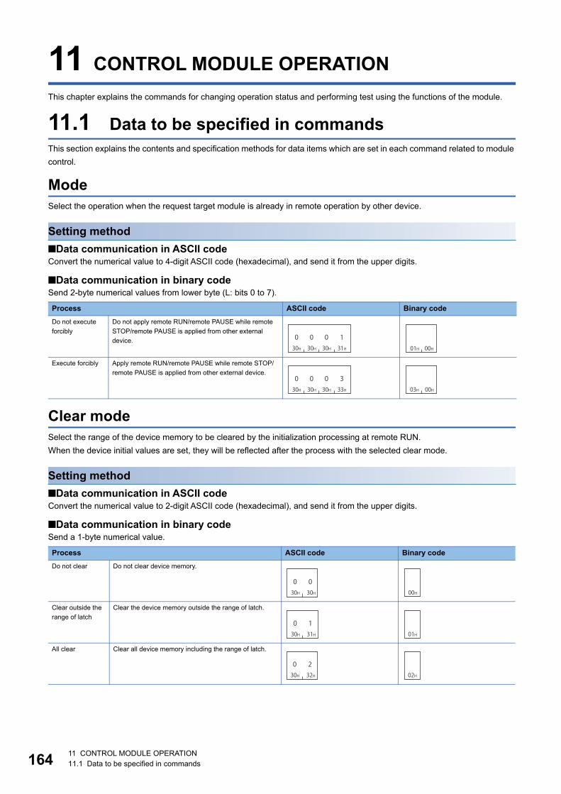
16411 CONTROL MODULE OPERATION11.1 Data to be specified in commands
11 CONTROL MODULE OPERATION
This chapter explains the commands for changing operation status and performing test using the functions of the module.
11.1 Data to be specified in commandsThis section explains the contents and specification methods for data items which are set in each command related to module
control.
ModeSelect the operation when the request target module is already in remote operation by other device.
Setting method
■Data communication in ASCII codeConvert the numerical value to 4-digit ASCII code (hexadecimal), and send it from the upper digits.
■Data communication in binary codeSend 2-byte numerical values from lower byte (L: bits 0 to 7).
Clear modeSelect the range of the device memory to be cleared by the initialization processing at remote RUN.
When the device initial values are set, they will be reflected after the process with the selected clear mode.
Setting method
■Data communication in ASCII codeConvert the numerical value to 2-digit ASCII code (hexadecimal), and send it from the upper digits.
■Data communication in binary codeSend a 1-byte numerical value.
Process ASCII code Binary code
Do not execute
forcibly
Do not apply remote RUN/remote PAUSE while remote
STOP/remote PAUSE is applied from other external
device.
Execute forcibly Apply remote RUN/remote PAUSE while remote STOP/
remote PAUSE is applied from other external device.
Process ASCII code Binary code
Do not clear Do not clear device memory.
Clear outside the
range of latch
Clear the device memory outside the range of latch.
All clear Clear all device memory including the range of latch.
030H
030H
030H
131H 01H 00H
030H
030H
030H
333H 03H 00H
030H
030H 00H
030H
131H 01H
030H
232H 02H
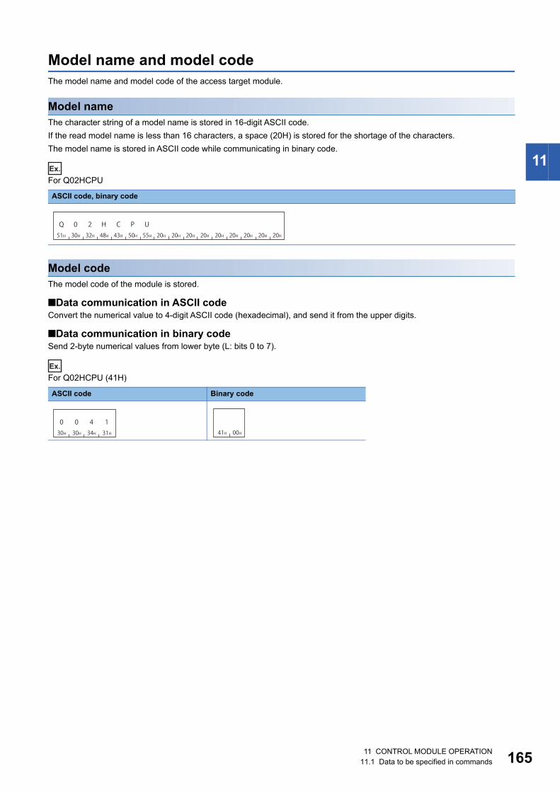
11 CONTROL MODULE OPERATION11.1 Data to be specified in commands 165
11
Model name and model codeThe model name and model code of the access target module.
Model nameThe character string of a model name is stored in 16-digit ASCII code.
If the read model name is less than 16 characters, a space (20H) is stored for the shortage of the characters.
The model name is stored in ASCII code while communicating in binary code.
Ex.
For Q02HCPU
Model codeThe model code of the module is stored.
■Data communication in ASCII codeConvert the numerical value to 4-digit ASCII code (hexadecimal), and send it from the upper digits.
■Data communication in binary codeSend 2-byte numerical values from lower byte (L: bits 0 to 7).
Ex.
For Q02HCPU (41H)
ASCII code, binary code
ASCII code Binary code
20H 20H 20H 20H 20H 20H 20H 20H
Q 0 251H 30H 32H
H48H
C P U43H 50H 55H 20H
030H
030H
434H
131H 41H 00H
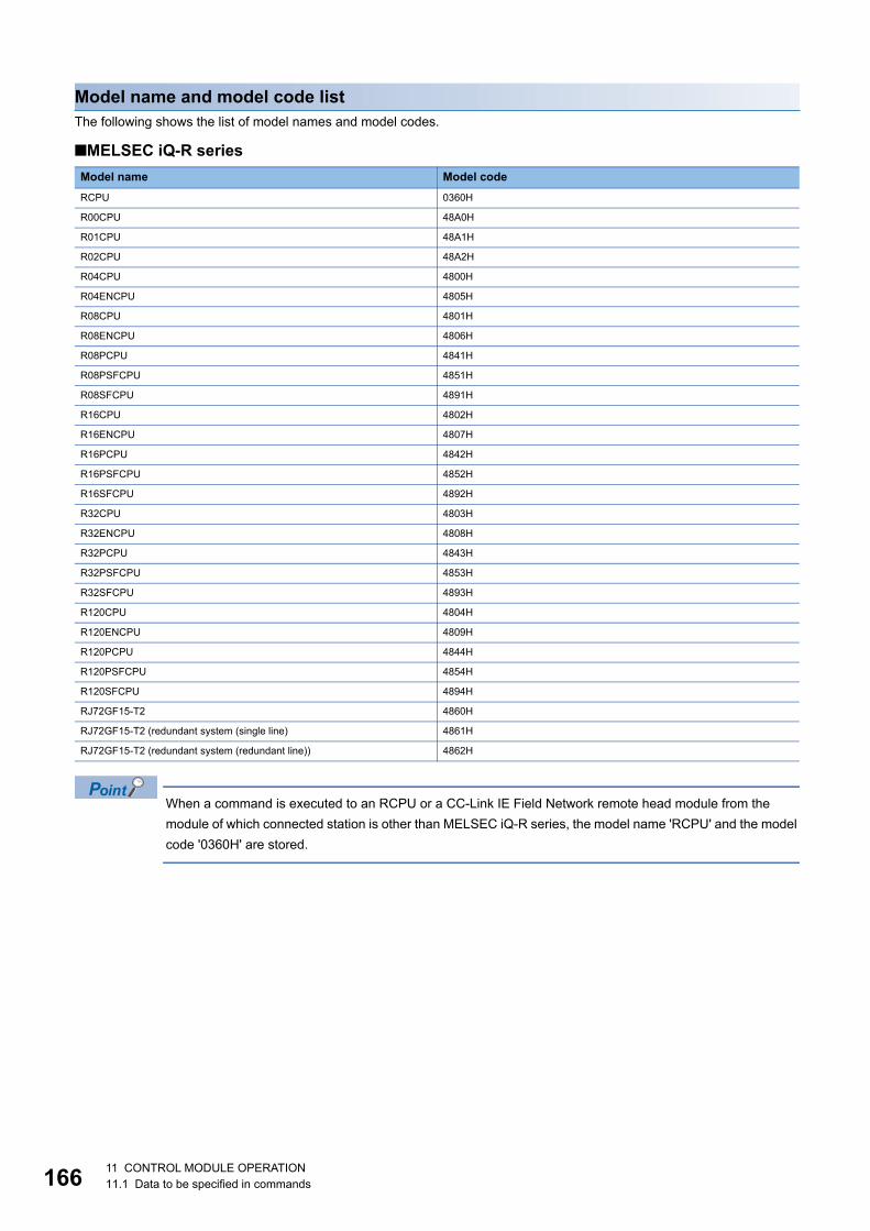
16611 CONTROL MODULE OPERATION11.1 Data to be specified in commands
Model name and model code listThe following shows the list of model names and model codes.
■MELSEC iQ-R series
When a command is executed to an RCPU or a CC-Link IE Field Network remote head module from the
module of which connected station is other than MELSEC iQ-R series, the model name 'RCPU' and the model
code '0360H' are stored.
Model name Model code
RCPU 0360H
R00CPU 48A0H
R01CPU 48A1H
R02CPU 48A2H
R04CPU 4800H
R04ENCPU 4805H
R08CPU 4801H
R08ENCPU 4806H
R08PCPU 4841H
R08PSFCPU 4851H
R08SFCPU 4891H
R16CPU 4802H
R16ENCPU 4807H
R16PCPU 4842H
R16PSFCPU 4852H
R16SFCPU 4892H
R32CPU 4803H
R32ENCPU 4808H
R32PCPU 4843H
R32PSFCPU 4853H
R32SFCPU 4893H
R120CPU 4804H
R120ENCPU 4809H
R120PCPU 4844H
R120PSFCPU 4854H
R120SFCPU 4894H
RJ72GF15-T2 4860H
RJ72GF15-T2 (redundant system (single line) 4861H
RJ72GF15-T2 (redundant system (redundant line)) 4862H

11 CONTROL MODULE OPERATION11.1 Data to be specified in commands 167
11
■MELSEC-L series
■MELSEC-Q series
Model name Model code
L02SCPU, L02SCPU-P 0543H
L02CPU, L02CPU-P 0541H
L06CPU, L06CPU-P 0544H
L26CPU, L26CPU-P 0545H
L26CPU-BT, L26CPU-PBT 0542H
LJ72GF15-T2 0641H
Model name Model code
Q00JCPU 0250H
Q00CPU 0251H
Q01CPU 0252H
Q02CPU, Q02HCPU, Q02PHCPU 0041H
Q06HCPU, Q06PHCPU 0042H
Q12HCPU, Q12PHCPU 0043H
Q25HCPU, Q25PHCPU 0044H
Q12PRHCPU 004BH
Q25PRHCPU 004CH
Q00UJCPU 0260H
Q00UCPU 0261H
Q01UCPU 0262H
Q02UCPU 0263H
Q03UDCPU, Q03UDECPU 0268H
Q03UDVCPU 0366H
Q04UDHCPU, Q04UDEHCPU 0269H
Q04UDVCPU 0367H
Q06UDHCPU, Q06UDEHCPU 026AH
Q06UDVCPU 0368H
Q10UDHCPU, Q10UDEHCPU 0266H
Q13UDHCPU, Q13UDEHCPU 026BH
Q13UDVCPU 036AH
Q20UDHCPU, Q20UDEHCPU 0267H
Q26UDHCPU, Q26UDEHCPU 026CH
Q26UDVCPU 036CH
Q50UDEHCPU 026DH
Q100UDEHCPU 026EH
QS001CPU 0230H

16811 CONTROL MODULE OPERATION11.1 Data to be specified in commands
Remote password
Remote password lengthSpecify the number of characters of remote password.
• For MELSEC-Q/L series modules, the character string is fixed to 4 characters.
• For MELSEC iQ-R series modules, specify the number of character string of the remote password (6 to 32 characters).
■Data communication in ASCII codeConvert the numerical value to 4-digit ASCII code (hexadecimal), and send it from the upper digits.
■Data communication in binary codeSend 2-byte *1 numerical values from lower byte (L: bits 0 to 7).
*1 For C24, the additional code may be added. (Page 35 Additional code (10H))
Ex.
For 4 characters, 32 characters
Remote passwordThe remote password is set by Engineering tool.
Specify the remote password in ASCII code while communicating in binary code.
Ex.
When password is 'ABCDEF'
Access target ASCII code Binary code
MELSEC-Q/L series module
(4 characters fixed)
MELSEC iQ-R series module
(32 characters)
ASCII code, binary code
030H
030H
030H
434H 04H 00H
030H
030H
232H
030H 20H 00H
A B C41H 42H 43H
D44H
E F45H 46H

11 CONTROL MODULE OPERATION11.1 Data to be specified in commands 169
11
Loopback data
Loopback data lengthNumber of bytes of loopback data.
■Data communication in ASCII codeConvert the numerical value to 4-digit ASCII code (hexadecimal), and send it from the upper digits.
■Data communication in binary codeSend 2-byte *1 numerical values from lower byte (L: bits 0 to 7).
*1 For C24, the additional code may be added. (Page 35 Additional code (10H))
Ex.
For 5 bytes
Loopback dataThe following characters can be used.
• 0 to 9 (30H to 39H)
• A to F (41H to 46H)
Specify the loopback data in ASCII code while communicating in binary code.
Ex.
For 'ABCDEF'
ASCII code Binary code
ASCII code, binary code
030H
030H
030H
535H 05H 00H
A B C41H 42H 43H
D44H
E F45H 46H

17011 CONTROL MODULE OPERATION11.1 Data to be specified in commands
Communication error informationA data to specify the communication error information to be initialized.
The data is equivalent to the buffer memory '0H', '1H' of MELSEC-Q/L series C24.
Specify the value (16-bit integer) in bit unit. The communication error information and its corresponding bit are as follows.
The communication error information to be initialized can be specified by turning the corresponding bit ON (1).
When the command is executed, the following corresponding bit of the buffer memory turns OFF (0).
"LED lighting status, communication error status" (Buffer memory 513 (201H), 514 (202H))
For MELSEC iQ-R series C24, specify '0'.
Setting method
■Data communication in ASCII codeConvert the numerical value to 4-digit ASCII code (hexadecimal), and send it from the upper digits.
■Data communication in binary codeSend 2-byte *1 numerical values from lower byte (L: bits 0 to 7).
*1 For C24, the additional code may be added. (Page 35 Additional code (10H))
Ex.
When initializing C/N, P/S, PRO, and SIO (bit 1 to 4) with MELSEC-Q/L series C24.
Ex.
For MELSEC iQ-R series
Item b15 b14 b13 to b8 b7 b6 b5 b4 b3 b2 b1 b0
Communication error information (CH1) NEU ACK NAK C/N P/S PRO SIO SD.WAIT
Communication error information (CH2) CH1.ERR CH2.ERR
Item ASCII code Binary code
Communication error information (CH1)
Communication error information (CH2)
Item ASCII code Binary code
Communication error information (CH1)
Communication error information (CH2)
030H
030H 31H
E45H
11EH 00H
030H
030H
030H
030H 00H 00H
030H
030H
030H
030H 00H 00H
030H
030H
030H
030H 00H 00H

11 CONTROL MODULE OPERATION11.2 Remote Operation 171
11
11.2 Remote OperationChange the operation status of CPU module.
For the remote operation function, refer to the manual of each CPU module.
• When powering OFF to ON or resetting the access target CPU after applying remote RUN/STOP/PAUSE,
the information of the remote operation will be cancelled. After powering OFF to ON or resetting CPU, the
CPU operates with the status of the switch on the CPU module.
• When the system protection of the access target module is enabled, the remote operation cannot be
performed and an error response will be returned. Disable the system protection of the CPU module.
• For E71, the communication using UDP/IP is recommended. For the communication using TCP/IP, re-
establishment of the connection is required because the connection is disconnected at resetting CPU
module.
• One communication of command provides remote operation for 1 station.
Remote RUN (command: 1001)Perform remote RUN for the access target module.
The command can be executed when the switch of the access target module is RUN. In the STOP status, the
command is completed normally, however, the access target CPU will not be in RUN status.
Message formatThe following shows the message format of the request data and response data of the command.
■Request data
■Response dataThere is no response data for this command.
Command Subcommand Mode Clear modeFixed values

17211 CONTROL MODULE OPERATION11.2 Remote Operation
Data specified by request data
■Command
*1 For C24, the additional code is added. (Page 35 Additional code (10H))
■Subcommand
■ModeSelect the operation when the request target module is already in remote operation by other device. (Page 164 Mode)
• 0001H: Do not execute forcibly
• 0003H: Execute forcibly
■Clear modeSelect the range of the device memory to be cleared by the initialization processing at remote RUN. (Page 164 Clear
mode)
• 00H: Do not clear
• 01H: Clear only outside the latch range
• 02H: All clear
■Fixed valueFixed to '0'.
Communication exampleRemote RUN is performed when the mode is set to "Do not execute forcibly", and the clear mode is set to "All clear".
■Data communication in ASCII code(Request data)
■Data communication in binary code(Request data)
ASCII code Binary code (for C24)*1 Binary code (for E71)
ASCII code Binary code
ASCII code Binary code
131H
030H
030H
131H 01H 10H 10H
DLE
01H 10H
030H
030H
030H
030H 00H 00H
030H
030H 00H
31H 30H 30H 31H 30H 30H 30H 30H 30H 30H 30H 31H 30H 32H 30H 30H
1 0 10 0 0 00 0 0 10 20 0 0
ClearmodeMode
01H 10H 00H 00H 01H 00H 00H02H
ClearmodeMode

11 CONTROL MODULE OPERATION11.2 Remote Operation 173
11
Remote STOP (command: 1002)Perform remote STOP for the access target module.
Message formatThe following shows the message format of the request data and response data of the command.
■Request data
■Response dataThere is no response data for this command.
Data specified by request data
■Command
*1 For C24, the additional code is added. (Page 35 Additional code (10H))
■Subcommand
■Fixed valueThe value is '0001H'.
Communication examplePerform remote STOP.
■Data communication in ASCII code(Request data)
■Data communication in binary code(Request data)
ASCII code Binary code (for C24)*1 Binary code (for E71)
ASCII code Binary code
Command SubcommandFixed values
131H
030H
030H
232H 02H 10H 10H
DLE
02H 10H
030H
030H
030H
030H 00H 00H
31H 30H 30H 32H 30H 30H 30H 30H 30H 30H 30H 31H
1 0 20 0 0 00 0 0 10
02H 10H 00H 00H 01H 00H

17411 CONTROL MODULE OPERATION11.2 Remote Operation
Remote PAUSE (command: 1003)Perform remote PAUSE for the access target module.
The command can be executed when the switch of the access target module is RUN. In the STOP status, the
command is completed normally, however, the access target CPU will not be in PAUSE status.
Message formatThe following shows the message format of the request data and response data of the command.
■Request data
■Response dataThere is no response data for this command.
Data specified by request data
■Command
*1 For C24, the additional code is added. (Page 35 Additional code (10H))
■Subcommand
■ModeSelect the operation when the request target module is already in remote operation by other device. (Page 164 Mode)
• 0001H: Do not execute forcibly
• 0003H: Execute forcibly
Communication exampleRemote PAUSE is performed when the mode is set to "Do not execute forcibly".
■Data communication in ASCII code(Request data)
■Data communication in binary code(Request data)
ASCII code Binary code (for C24)*1 Binary code (for E71)
ASCII code Binary code
Command Subcommand Mode
131H
030H
030H
333H 03H 10H 10H
DLE
03H 10H
030H
030H
030H
030H 00H 00H
31H 30H 30H 33H 30H 30H 30H 30H 30H 30H 30H 31H
1 0 0 3 0 0 0 0 0 0 0 1
03H 10H 00H 00H 01H 00H

11 CONTROL MODULE OPERATION11.2 Remote Operation 175
11
Remote latch clear (command: 1005)Perform remote latch clear for the access target module.
• Execute the command after changing the status of the access target module to STOP.
• The remote latch clear cannot be performed when the access target CPU is in remote STOP or remote
PAUSE by other devices. The command will be terminated abnormally. Clear the remote STOP or remote
PAUSE before executing the command.
Message formatThe following shows the message format of the request data and response data of the command.
■Request data
■Response dataThere is no response data for this command.
Data specified by request data
■Command
*1 For C24, the additional code is added. (Page 35 Additional code (10H))
■Subcommand
■Fixed valueThe value is '0001H'.
Communication examplePerform remote latch clear.
■Data communication in ASCII code(Request data)
■Data communication in binary code(Request data)
ASCII code Binary code (for C24)*1 Binary code (for E71)
ASCII code Binary code
Command Subcommand Fixed values
131H
030H
030H
535H 05H 10H 10H
DLE
05H 10H
030H
030H
030H
030H 00H 00H
31H 30H 30H 35H 30H 30H 30H 30H 30H 30H 30H 31H
1 0 0 5 0 0 0 0 0 0 0 1
05H 10H 00H 00H 01H 00H

17611 CONTROL MODULE OPERATION11.2 Remote Operation
Remote RESET (command: 1006)Perform remote RESET for the access target module.
• Execute the command after changing the status of the access target module to STOP. If the CPU module is
stopped due to the error, the command can be executed even when the switch of the CPU module is in the
position of RUN,
• If a remote RESET operation enable/disable setting exists in the access target parameter, set it to enable.
• Remote RESET may not be performed due to the hardware error of the access target device.
• When performing remote RESET, the response message may not be returned because the access target
CPU is reset.
Message formatThe following shows the message format of the request data and response data of the command.
■Request data
■Response dataThere is no response data for this command.
Data specified by request data
■Command
*1 For C24, the additional code is added. (Page 35 Additional code (10H))
■Subcommand
■Fixed valueThe value is '0001H'.
Communication examplePerform remote RESET.
■Data communication in ASCII code(Request data)
■Data communication in binary code(Request data)
ASCII code Binary code (for C24)*1 Binary code (for E71)
ASCII code Binary code
Command Subcommand Fixed values
131H
030H
030H
636H 06H 10H 10H
DLE
06H 10H
030H
030H
030H
030H 00H 00H
31H 30H 30H 36H 30H 30H 30H 30H 30H 30H 30H 31H
1 0 60 0 0 00 0 0 10
06H 10H 00H 00H 01H 00H
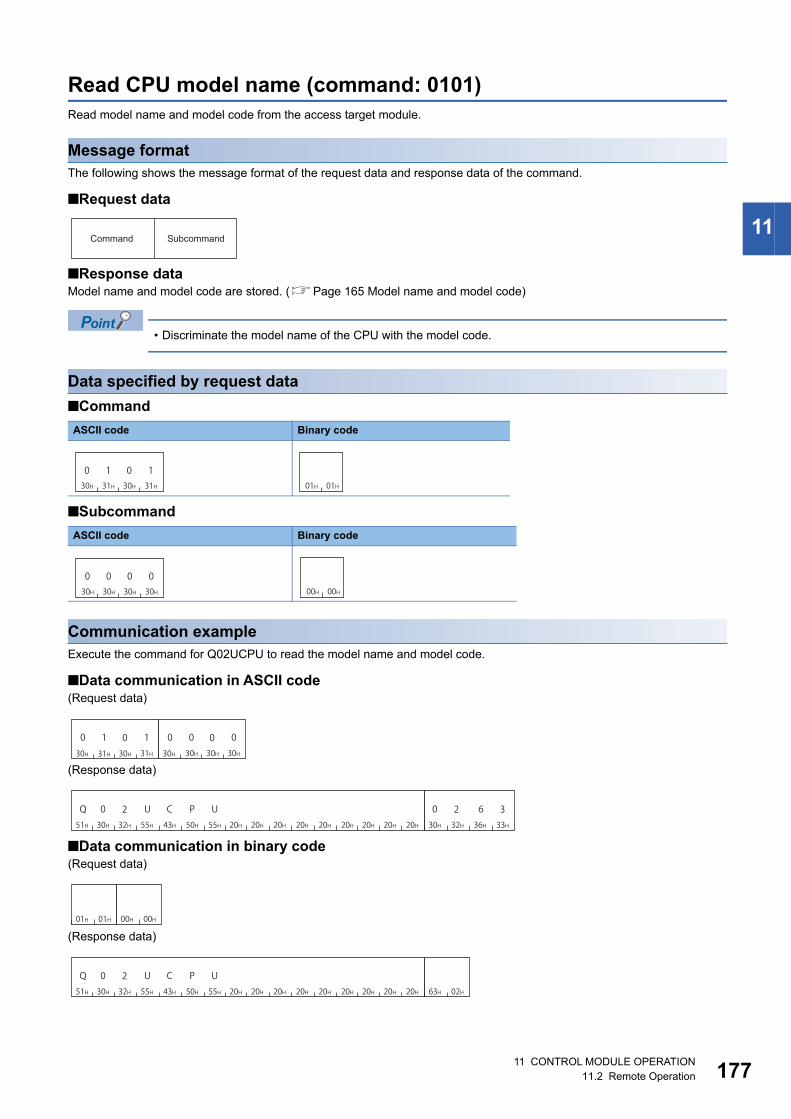
11 CONTROL MODULE OPERATION11.2 Remote Operation 177
11
Read CPU model name (command: 0101)Read model name and model code from the access target module.
Message formatThe following shows the message format of the request data and response data of the command.
■Request data
■Response dataModel name and model code are stored. (Page 165 Model name and model code)
• Discriminate the model name of the CPU with the model code.
Data specified by request data
■Command
■Subcommand
Communication exampleExecute the command for Q02UCPU to read the model name and model code.
■Data communication in ASCII code(Request data)
(Response data)
■Data communication in binary code(Request data)
(Response data)
ASCII code Binary code
ASCII code Binary code
Command Subcommand
030H
131H
030H
131H 01H 01H
030H
030H
030H
030H 00H 00H
30H 31H 30H 31H 30H 30H 30H 30H
0 1 10 0 0 00
51H 30H 32H 55H 43H 50H 55H 20H 20H 20H 20H 20H 20H 20H 20H 20H 30H 32H 36H 33H
Q 0 U2 C P U 0 2 6 3
01H 01H 00H 00H
51H 30H 32H 55H 43H 50H 55H 20H 20H 20H 20H 20H 20H 20H 20H 20H 63H 02H
Q 0 U2 C P U

17811 CONTROL MODULE OPERATION11.3 Remote Password
11.3 Remote PasswordThis section explains the commands that unlock or lock the remote password.
For details on the remote password, refer to the manuals of access target CPU or CPU module.
The command can only be used for C24 (including multidrop connection station) and E71 connected to the
external device. It cannot be used via network.
For the modem connection, access route must be set as the same route as that of the connected station (host
station).
(Page 45 ACCESS ROUTE SETTINGS)
Execution procedureThe communication with the module in which the remote password is set, follow the procedure shown below.
1. Line connection by modem (C24)/open processing for connection (E71)
2. Access permission (unlock processing) (Page 179 Unlock (command: 1630))
3. Access processing
Perform data communication by various commands of MC protocol.
4. Access prohibition (lock processing) (Page 181 Lock (command: 1631))
For C24 or TCP/IP communication of E71, the lock processing is performed automatically at modem disconnection/close
processing.
5. Line disconnection/close processing of connection
All the commands received when the remote password is locked will be an error response. Perform data
communication after the unlock processing.

11 CONTROL MODULE OPERATION11.3 Remote Password 179
11
Unlock (command: 1630)Specify the remote password to unlock the module. (The module can communicate.)
If the incorrect password is entered several times, the password is locked out and cannot be cleared for a
while.
When the command is sent to the unlocked module, the unlock status is not changed. (The password
verification is not performed.)
Message formatThe following shows the message format of the request data and response data of the command.
■Request data
■Response dataThere is no response data for this command.
Data specified by request data
■Command
■Subcommand
■Remote password lengthSpecify the number of characters of remote password. (Page 168 Remote password length)
■Remote passwordSpecify the set remote password. (Page 168 Remote password)
ASCII code Binary code
ASCII code Binary code
Command Subcommand Remote password length Remote password
131H
636H
333H
030H 30H 16H
030H
030H
030H
030H 00H 00H

18011 CONTROL MODULE OPERATION11.3 Remote Password
Communication example (for MELSEC-Q series)Unlock the MELSEC-Q/L series module in which the following remote password has been set.
• Remote password: '1234' (4 characters)
■Data communication in ASCII code(Request data)
■Data communication in binary code(Request data)
Communication example (for the files of MELSEC iQ-R series)Unlock the MELSEC iQ-R series module in which the following remote password has been set.
• Remote password: 'abcdefghijklmnopqrstuvwxyz' (26 characters)
■Data communication in ASCII code(Request data)
■Data communication in binary code(Request data)
31H 36H 33H 30H 30H 30H 30H 30H 30H 30H 30H 34H
00000000361 431H 32H 33H 34H
4321
Remote password lengthSubcommand Remote password
30H 16H 00H 00H 04H 00H 31H 32H 33H 34H
4321
Remote password length
Remote passwordSubcommand
31H 36H 33H 30H 30H 30H 30H 30H 30H 30H 31H 41H
10000000361 A
65H 66H 67H 68H
hgfe6DH 6EH
m n6FH
o70H
p71H
q72H
r73H
s74H
t75H
u76H
v77H
w78H
x79H
y7AH
z69H 6AH 6BH 6CH
kji l61H 62H 63H 64H
dcba
Remote password lengthSubcommand
Remote password
30H 16H 00H 00H 1AH 00H
65H 66H 67H 68H
hgfe6DH 6EH
m n6FH
o70H
p71H
q72H
r73H
s74H
t75H
u76H
v77H
w78H
x79H
y7AH
z69H 6AH 6BH 6CH
kji l61H 62H 63H 64H
dcba
Remote password length
Remote password
Subcommand

11 CONTROL MODULE OPERATION11.3 Remote Password 181
11
Lock (command: 1631)Specify the remote password to lock the module. (The module cannot communicate.)
When the command is sent to the locked module, the lock status is not changed. (The password verification is
not performed.)
Message formatThe following shows the message format of the request data and response data of the command.
■Request data
■Response dataThere is no response data for this command.
Data specified by request data
■Command
■Subcommand
■Remote password lengthSpecify the number of characters of remote password. (Page 168 Remote password length)
■Remote passwordSpecify the set remote password. (Page 168 Remote password)
ASCII code Binary code
ASCII code Binary code
Command Subcommand Remote password length Remote password
131H
636H
333H
131H 31H 16H
030H
030H
030H
030H 00H 00H

18211 CONTROL MODULE OPERATION11.3 Remote Password
Communication example (for MELSEC-Q series)Lock the MELSEC-Q/L series module in which the following remote password has been set.
• Remote password: '1234' (4 characters)
■Data communication in ASCII code(Request data)
■Data communication in binary code(Request data)
Communication example (for the files of MELSEC iQ-R series)Lock the MELSEC iQ-R series module in which the following password has been set.
• Remote password: 'abcdefghijklmnopqrstuvwxyz' (26 characters)
■Data communication in ASCII code(Request data)
■Data communication in binary code(Request data)
31H 36H 33H 31H 30H 30H 30H 30H 30H 30H 30H 34H
00000001361 431H 32H 33H 34H
4321
Remote password lengthSubcommand Remote password
31H 16H 00H 00H 04H 00H 31H 32H 33H 34H
4321
Remote password length
Remote passwordSubcommand
31H 36H 33H 31H 30H 30H 30H 30H 30H 30H 31H 41H
10000001361 A
65H 66H 67H 68H
hgfe6DH 6EH
m n6FH
o70H
p71H
q72H
r73H
s74H
t75H
u76H
v77H
w78H
x79H
y7AH
z69H 6AH 6BH 6CH
kji l61H 62H 63H 64H
dcba
Remote password lengthSubcommand
Remote password
31H 16H 00H 00H 1AH 00H
65H 66H 67H 68H
hgfe6DH 6EH
m n6FH
o70H
p71H
q72H
r73H
s74H
t75H
u76H
v77H
w78H
x79H
y7AH
z69H 6AH 6BH 6CH
kji l61H 62H 63H 64H
dcba
Remote password length
Remote password
Subcommand
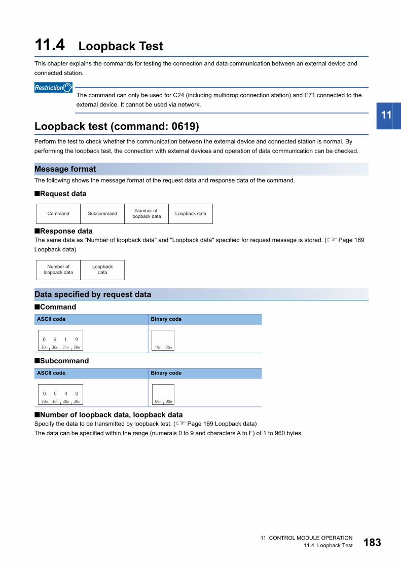
11 CONTROL MODULE OPERATION11.4 Loopback Test 183
11
11.4 Loopback TestThis chapter explains the commands for testing the connection and data communication between an external device and
connected station.
The command can only be used for C24 (including multidrop connection station) and E71 connected to the
external device. It cannot be used via network.
Loopback test (command: 0619)Perform the test to check whether the communication between the external device and connected station is normal. By
performing the loopback test, the connection with external devices and operation of data communication can be checked.
Message formatThe following shows the message format of the request data and response data of the command.
■Request data
■Response dataThe same data as "Number of loopback data" and "Loopback data" specified for request message is stored. (Page 169
Loopback data)
Data specified by request data
■Command
■Subcommand
■Number of loopback data, loopback dataSpecify the data to be transmitted by loopback test. (Page 169 Loopback data)
The data can be specified within the range (numerals 0 to 9 and characters A to F) of 1 to 960 bytes.
ASCII code Binary code
ASCII code Binary code
Command Subcommand Number of loopback data Loopback data
Number of loopback data
Loopback data
030H
636H
131H
939H 19H 06H
030H
030H
030H
030H 00H 00H

18411 CONTROL MODULE OPERATION11.4 Loopback Test
Communication examplePerform the loopback test with the following loopback data.
• Loopback data: 'ABCDE" (5 characters)
■Data communication in ASCII code(Request data)
(Response data)
■Data communication in binary code(Request data)
(Response data)
30H 36H 31H 39H 30H 30H 30H 30H 30H 30H 30H 35H 41H 42H 43H 44H 45H
0 6 91 0 0 00 0 0 50 A B C D E
Subcommand Number of loopback data Loopback data
30H 30H 30H 35H 41H 42H 43H 44H 45H
0 0 0 5 A B C D E
Number of loopback data Loopback data
19H 06H 00H 00H 05H 00H 41H 42H 43H 44H 45H
A B C D E
SubcommandNumber of loopback data Loopback data
05H 00H 41H 42H 43H 44H 45H
A B C D E
Loopback dataNumber of loopback data

11 CONTROL MODULE OPERATION11.5 Clear Error Information 185
11
11.5 Clear Error InformationThis section explains the command to initialize LED display and error information of buffer memory, and recover the
supported device.
For details of the related LEDs, input/output signals, and buffer memory, refer to the manual of the access target module.
Turn indicator LED OFF, initialize error code (command: 1617)Turn OFF the indicator LED of the serial communication module, and initialize the communication error information and error
codes.
The command can only be used for C24 (including multidrop connection station) connected to the external
device. It cannot be used via network.
Message formatThe following shows the message format of the request data and response data of the command.
■Request data
■Response dataThere is no response data for this command.
Data specified by request data
■Command
ASCII code Binary code
Command Subcommand Communication error information (CH1)
Communication error information (CH2)
131H
636H
131H
737H 17H 16H

18611 CONTROL MODULE OPERATION11.5 Clear Error Information
■Subcommand
For C24 of MELSEC-Q/L series, 0 to 3 bits of subcommands are equivalent to the following functions of C24.
The settings in the table above is recommended, even though the initialization can be performed with the
values (0001H to 000FH) which combined ON/OFF arbitrarily.
• Bit 0: CH1 Error initialization request (YE) ON
• Bit 1: CH2 Error initialization request (YF) ON
• Bit 2: LED for CH1 OFF, communication error information initialization request (buffer memory address: 0H)
ON
• Bit 3: LED for CH2 OFF, communication error information initialization request (buffer memory address: 1H)
ON
■Communication error informationSpecify the items in "LED lighting status, communication error status" to be initialized. (Page 170 Communication error
information)
For MELSEC iQ-R series C24, specify '0'.
Communication examplePerform the following operations for CH1 interface of QJ71C24N-R2.
• ERR LED: OFF
• Input signal XE "Error occurrence": OFF
• Buffer memory 513 (201H) "LED lighting status, communication error status": Initialized (all items are OFF)
• Error code of buffer memory: Initialized (clear)
■Data communication in ASCII code(Request data)
■Data communication in binary code(Request data)
Target ASCII code Binary code
MELSEC-Q/L series CH1 side
CH2 side
CH1 side, CH2
side
MELSEC iQ-R series CH1 side, CH2
side
030H
030H
030H
535H 05H 00H
030H
030H
030H
A41H 0AH 00H
030H
030H 30H
F46H
00FH 00H
030H
030H
030H
131H 01H 00H
31H 36H 33H 31H 30H 30H 30H 35H 30H 30H 46H 46H
F0050007161 F30H 30H 30H 30H
0000
Communication error information (CH1)
Communication error information (CH2)Subcommand
17H 16H 05H 00H FFH 00H 00H 00H
Communication error information (CH1)
Communication error information (CH2)Subcommand

11 CONTROL MODULE OPERATION11.5 Clear Error Information 187
11
Turn COM.ERR. LED OFF (command: 1617)Turn the COM.ERR.LED of Ethernet interface module OFF.
The commands can be used for E71 connected to an external device and cannot be used via network.
Message formatThe following shows the message format of the request data and response data of the command.
■Request data
■Response dataThere is no response data for this command.
Data specified by request data
■Command
■Subcommand
Communication exampleTurn COM.ERR.LED OFF.
■Data communication in ASCII code(Request data)
■Data communication in binary code(Request data)
ASCII code Binary code
ASCII code Binary code
Command Subcommand
131H
636H
131H
737H 17H 16H
030H
030H
030H
030H 00H 00H
31H 36H 33H 31H 30H 30H 30H 30H
00007161
Subcommand
17H 16H 00H 00H
Subcommand

18812 FILE CONTROL12.1 Execution Procedure
12 FILE CONTROL
This chapter explains the commands that operates files in the supported devices the CPU module.
Use this function in the following situations:
• To check the parameters and programs stored in the CPU module
• To change the parameters and programs in the CPU module according to the control content
For file name, extension, and storage location of files that can be handled by MC protocol, refer to the manual of the module
to be accessed.
12.1 Execution ProcedureThe following shows the file control procedures.
Procedure to read information from all files in directory (folder)1. Read the file information from the head of the file.
Specify '1' for "Head file No." and '36' (upper limit) for "Number of requested file", and execute the 'read directory/file
information' command. The file information of "Number of file information" is stored in the response data.
Page 209 Read directory/file information (command: 1810)
2. Check if there is a file from which the file information is not read.
When "Number of file information" of the response data is in the status as shown below, it indicates that file information of all
the files have been read. Complete the processing.
• MELSEC-Q/L series (when using subcommand '0000'): "Number of file information" < "Number of requested file"
• MELSEC iQ-R series (when using subcommand '0040'): "Number of file information" = -1 (FFFFH)
3. Read the file information from a file from which the file information is not read.
Specify "Number of requested file" = 36 (upper limit) to the request data, and execute the command.
For "Head file No.", specify one of the following value.
• MELSEC-Q/L series (when using subcommand '0000'): "Head file No." = previous "Head file No." + "Number of file
information"
• MELSEC iQ-R series (when using subcommand '0040'): "Head file No." = previous "Last file No." + 1
Page 209 Read directory/file information (command: 1810)
4. Repeat the procedure of Step 2 and later.
The correct information cannot be obtained if the file operation is performed from other devices while reading
information of all the files in the directory. Do not perform file operation from other devices while reading file
information.

12 FILE CONTROL12.1 Execution Procedure 189
12
Procedure to read files1. Check for file existence.
Any of the following commands can be used.
• Page 209 Read directory/file information (command: 1810)
• Page 215 Search directory/file information (command: 1811)
2. Read the files.
For read command, use open and close command to prohibit access from other devices.
Execute the commands in the following order.
• Page 234 Open file (command: 1827)
• Page 238 Read file (command: 1828)
• Page 242 Close file (command: 182A)
Procedure to overwrite files1. Check for file existence.
Any of the following commands can be used.
• Page 209 Read directory/file information (command: 1810)
• Page 215 Search directory/file information (command: 1811)
2. Write data to the file.
For writing data, use open and close command to prohibit access from other devices.
Execute the commands in the following order.
• Page 234 Open file (command: 1827)
• Page 240 Write to file (command: 1829)
• Page 242 Close file (command: 182A)
In the following cases, create a new file and write data to it after deleting the target file.
• When the target file is sequence program file (*.PRG) or FB file (*.PFB) of MELSEC iQ-R series.
• When changing the file size of MELSEC-Q/L series is required.
Page 191 Procedure to delete files
Page 190 Procedure to create new file and write data
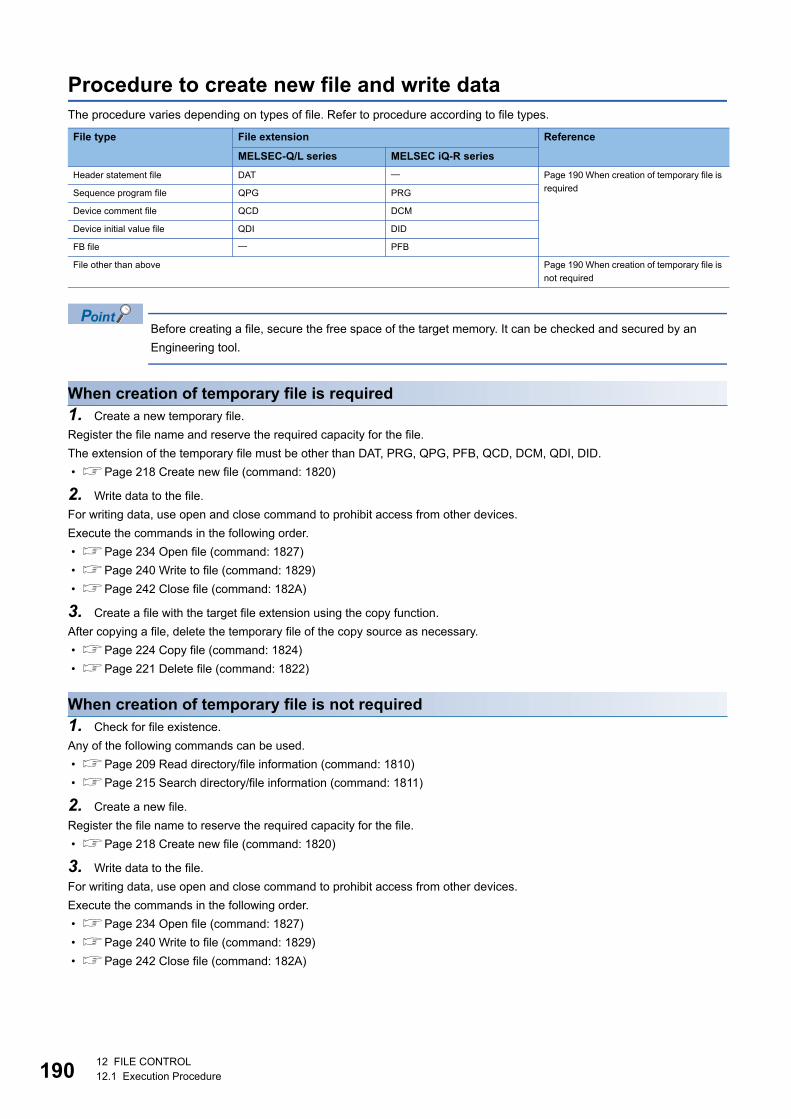
19012 FILE CONTROL12.1 Execution Procedure
Procedure to create new file and write dataThe procedure varies depending on types of file. Refer to procedure according to file types.
Before creating a file, secure the free space of the target memory. It can be checked and secured by an
Engineering tool.
When creation of temporary file is required1. Create a new temporary file.
Register the file name and reserve the required capacity for the file.
The extension of the temporary file must be other than DAT, PRG, QPG, PFB, QCD, DCM, QDI, DID.
• Page 218 Create new file (command: 1820)
2. Write data to the file.
For writing data, use open and close command to prohibit access from other devices.
Execute the commands in the following order.
• Page 234 Open file (command: 1827)
• Page 240 Write to file (command: 1829)
• Page 242 Close file (command: 182A)
3. Create a file with the target file extension using the copy function.
After copying a file, delete the temporary file of the copy source as necessary.
• Page 224 Copy file (command: 1824)
• Page 221 Delete file (command: 1822)
When creation of temporary file is not required1. Check for file existence.
Any of the following commands can be used.
• Page 209 Read directory/file information (command: 1810)
• Page 215 Search directory/file information (command: 1811)
2. Create a new file.
Register the file name to reserve the required capacity for the file.
• Page 218 Create new file (command: 1820)
3. Write data to the file.
For writing data, use open and close command to prohibit access from other devices.
Execute the commands in the following order.
• Page 234 Open file (command: 1827)
• Page 240 Write to file (command: 1829)
• Page 242 Close file (command: 182A)
File type File extension Reference
MELSEC-Q/L series MELSEC iQ-R series
Header statement file DAT Page 190 When creation of temporary file is
requiredSequence program file QPG PRG
Device comment file QCD DCM
Device initial value file QDI DID
FB file PFB
File other than above Page 190 When creation of temporary file is
not required

12 FILE CONTROL12.1 Execution Procedure 191
12
Procedure to delete files1. Check for file existence.
Any of the following commands can be used.
• Page 209 Read directory/file information (command: 1810)
• Page 215 Search directory/file information (command: 1811)
2. Delete the file.
• Page 221 Delete file (command: 1822)
Procedure to copy files
Before copying file, secure the free area of the target memory. It can be checked and secured with
Engineering tool.
1. Check for file existence.
Any of the following commands can be used.
• Page 209 Read directory/file information (command: 1810)
• Page 215 Search directory/file information (command: 1811)
2. Copy the file.
After copying a file, delete the file of the copy source as necessary.
• Page 224 Copy file (command: 1824)
• Page 221 Delete file (command: 1822)
Procedure to modify file creation date and timeModify the date of file creation by the 'modify file creation date and time' (command: 1826).
Page 231 Modify file creation date and time (command: 1826)

19212 FILE CONTROL12.2 Considerations
12.2 ConsiderationsThe following shows the considerations for file control.
Files such as read programs and parametersIf the files such as program files and parameters which affect the system are read from the CPU module, keep the files for
backup. Do not edit the data in the file on an external device. If the programs or parameters are required to be changed, use
an Engineering tool.
Access for '$MELPRJ$' folder of RCPUThe $MELPRJ$ folder of RCPU is the folder that controls the data written from an Engineering. Do not access the $MELPRJ$
folder other than the purpose of data backup or restoration.
When performing data backup or restoration in the '$MELPRJ$' folder, read/write all the files in the '$MELPRJ$' folder. If only
a part of '$MELPRJ$' folder is changed, it may not operate properly.
If the file is protectedWhen executing the following command, disable the protection (system protect of CPU module, the protection switch of SD
memory card) of the access target CPU. If the command is executed with the access target protected, the command will be
terminated abnormally.
Files that cannot be modified while CPU module is in RUNThe executing file cannot be modified while the CPU module is in RUN.
When data write or delete command is executed to a file being executed, place CPU module in the STOP status. If the
command is executed during RUN, the command completes abnormally.
Page 462 Applicable Commands for Online Program Change
Function Reference
Create new file (Register file name) Page 218 Create new file (command: 1820)
Delete file Page 221 Delete file (command: 1822)
Copy file Page 224 Copy file (command: 1824)
Modify file attribute Page 228 Modify file attribute (command: 1825)
Modify file creation date and time Page 231 Modify file creation date and time (command: 1826)
Write to file Page 240 Write to file (command: 1829)

12 FILE CONTROL12.3 Data to be specified in commands 193
12
12.3 Data to be specified in commandsThis section explains the contents and specification methods for data items which are set in each command related to file
control.
PasswordSpecify the password of the file to be accessed.
The specification of a password differs depending on the module. Specify a password which corresponds to the module of
access target.
For details on the password, refer to the manual of access target module.
*1 If the password is less than 32 characters, append a space (code: 20H).
Password for MELSEC-Q series module (4 characters)Use the subcommand '0000'.
■When a password is setSend password character string in 4-digit ASCII code.
Specify the password in ASCII code during data communication in binary code as well.
Ex.
When the password is 'ABCD'
When setting the password with the file password 32 function of High-speed universal model QCPU, set it with
four characters.
■When a password is not setSpecify 20H for 4 bytes.
Access target Password to be set Sub command Data specified by Message
MELSEC-Q series module Password (4 characters) 0000 Password character string (fixed to 4 characters)
File password 32 (4 characters)
MELSEC-L series module File password 32 (4 to 32 characters) 0004 Password character string (fixed to 32 characters)*1
MELSEC iQ-R series module File password (6 to 32 characters) 0040 Number of password characters, password character string
(variable length)
ASCII code, binary code
ASCII code, binary code
A41H
B42H
C43H
D44H
20H 20H 20H 20H

19412 FILE CONTROL12.3 Data to be specified in commands
File password 32 of MELSEC-L series (4 to 32 characters)Use the subcommand '0004'.
Subcommand '0000' can be used only when the password is not set to the file.
When subcommand 0000 is used to MELSEC-L series module, specify 20H for 4 bytes.
■When a password is setSend password character string in 32-digit ASCII code.
Specify the password in ASCII code during data communication in binary code as well.
If the password is less than 32 characters, a space (20H) is added for the shortage of the characters.
Ex.
When the password is 'ABCDEF'
■When a password is not setSpecify 20H for 32 bytes.
ASCII code, binary code
ASCII code, binary code
A41H
B42H
C D44H
E F45H 46H 20H 20H 20H43H(32 digits)
20H 20H 20H 20H 20H 20H 20H 20H 20H(32 digits)

12 FILE CONTROL12.3 Data to be specified in commands 195
12
File password for MELSEC iQ-R series (6 to 32 characters)Use the subcommand '0040'.
If multiple wrong passwords are attempted continuously, the password will be locked out and cannot unlock
the password for a while.
■When a password is setSpecify the number of characters and the character string of password.
Specify 'Password character string' with variable length. The length of data is specified in 'Number of characters'. (Page
198 Number of characters)
Specify the password character string in ASCII code during data communication in binary code as well.
Ex.
Password is "ABCDEFGHIJKLMNOPQRSTUVWXYZ" (26 characters)
■When a password is not setSpecify with the number of character '0'.
ASCII code Binary code
ASCII code Binary code
ASCII code Binary code
Number of characters Password character string
(4 digits) (Variable length)
Number of characters Password character string
(2 bytes) (Variable length)
30H 30H 31H 41H 41H 42H 43H 44H 5AH
0 0 1 A A B C D Z
Number of characters Password character string
1AH 00H 41H 42H 43H 44H 5AH
A B DC ・・・ Z
Number of characters Password character string
030H
030H
030H
030H 00H 00H

19612 FILE CONTROL12.3 Data to be specified in commands
Drive No.This is a data to specify the drive in a CPU module of which files are to be managed.
The program memory of RCPU cannot be accessed. When reading/writing program files, use the data
memory. (Page 192 Access for '$MELPRJ$' folder of RCPU)
Setting method
■Data communication in ASCII codeConvert the numerical value that indicates access target drive to 4-digit ASCII code (hexadecimal), and send it from the upper
digits.
■Data communication in binary codeSend 2-byte numerical values that indicate access target drive from the lower byte (L: bits 0 to 7).
Ex.
Drive No. is '0003H'
Specified value Target drive
RCPU LCPU/QCPU/QnACPU
0000H Program memory
0001H Device/label memory (file storage area)
The same operation when 0003H is specified.
SRAM card
0002H SD memory card Flash card, ATA card, SD memory card
0003H Device/label memory (file storage area) Standard RAM
0004H Data memory Standard ROM
ASCII code Binary code
030H
030H
030H
333H 03H 00H

12 FILE CONTROL12.3 Data to be specified in commands 197
12
File No.This is a number for module to control files.
File No. can be obtained by following command.
Page 215 Search directory/file information (command: 1811)
File No. of MELSEC-Q/L series moduleUse the subcommand '0000'.
A file No. can be specified within the range of 1 to 256 (1H to 100H).
■Data communication in ASCII codeConvert the file No. to 4-digit ASCII code (hexadecimal), and send it from the upper digits.
■Data communication in binary codeSend 2-byte*1 numerical values that indicate file No. from lower byte (L: bits 0 to 7).
*1 For C24, the additional code may be added. (Page 35 Additional code (10H))
Ex.
1FH
File No. of MELSEC iQ-R series moduleUse the subcommand '0040'.
■Data communication in ASCII codeConvert the file No. to ASCII code 8 digits (hexadecimal), and transmit it from the upper digits.
■Data communication in binary codeSend 4-byte*1 numerical values that indicate file No. from the lower byte (L: bits 0 to 7).
*1 For C24, the additional code may be added. (Page 35 Additional code (10H))
Ex.
For 1FH
ASCII code Binary code
ASCII code Binary code
030H
030H
131H
F46H 1FH 00H
0 0 030H 30H 30H
030H
0 0 130H 30H 31H
F 46H 1FH 00H 00H 00H

19812 FILE CONTROL12.3 Data to be specified in commands
Number of filesSpecify the number of files to be accessed. The number of registered files or the number of accessed files are returned.
Setting method
■Data communication in ASCII codeConvert the numerical value to 4-digit ASCII code (hexadecimal), and send it from the upper digits.
■Data communication in binary codeSend 2-byte numerical values*1 from the lower byte (L: bits 0 to 7).
*1 For C24, the additional code may be added. (Page 35 Additional code (10H))
Ex.
Number of file is 3
Number of charactersThis indicates the number of characters of variable length character string to be specified.
Setting method
■Data communication in ASCII codeConvert the numerical value to 4-digit ASCII code (hexadecimal), and send it from the upper digits.
■Data communication in binary codeSend 2-byte numerical values*1 from the lower byte (L: bits 0 to 7).
*1 For C24, the additional code may be added. (Page 35 Additional code (10H))
Ex.
Number of characters is 86 characters (56H)
Directory specificationSpecify the absolute path to a file to be accessed.
Specify 'Path name' with variable length. The length of data is specified in 'Number of characters'. (Page 198 Number of
characters)
Specify '0' for the root directory (root folder)
ASCII code Binary code
ASCII code Binary code
ASCII code Binary code
ASCII code Binary code
030H
030H
030H
333H 03H 00H
030H
030H
535H
636H 56H 00H
Number of characters Path name
(4 digits) (Variable length)
Number of characters Path name
(2 bytes) (Variable length)
030H
030H
030H
030H 00H 00H

12 FILE CONTROL12.3 Data to be specified in commands 199
12
Path nameSpecify the absolute path by UTF-16 from the root folder.
"Drive name:\" is not required in front of the path. Use '\' (005CH) for the delimiter between the folder names.
■Data communication in ASCII codeConvert the numerical value of UTF-16, which indicates a path character string, to ASCII code (hexadecimal), and send it
from the upper digits.
■Data communication in binary codeSend the numerical value of UTF-16 indicating the path character string from lower bytes (L: bits 0 to 7).
Ex.
Folder root folder 'A'
(UTF-16: 'A'= 0041)
ASCII code Binary code
030H
030H
434H
131H 41H 00H

20012 FILE CONTROL12.3 Data to be specified in commands
File name specificationSpecify the file name to be accessed.
A file name differs in specification by the module. Specify a corresponding file name for the module of access target. For
details of usable file name, refer to the manual of module for access target.
Files other than the one described as usable files in the manuals of modules are for system. Do not change
the file name.
File name of MELSEC-Q/L series module (File name and extension)When using the subcommand 0000 for the read directory/file information (command: 1810), the file name (8 characters fixed)
and the extension (3 characters fixed) are stored in the response data. A period is not inserted between the file name and the
extension.
Specify the file name and the extension in ASCII code during data communication in binary code as well.
Ex.
The file name and the extension are "ABCDEFGH.QPG".
Access target Usable file name Sub command Data specified by Message
MELSEC-Q/L series module File name (up to 8 characters) and
extension (3 characters)
Specify with ASCII code character string.
0000
0004
• File name (8 characters fixed) and extension (3
characters fixed)
• Number of characters (up to 12 characters) and file
name character string (including the extension)
MELSEC iQ-R series module Path name, file name (up to 60
characters) and extension
Specify with Unicode character string.
0040 • Number of characters (up to 252 characters) and file
name character string (including the path and extension)
ASCII code, binary code
ASCII code, binary code
File name Extension
(8 digits) (3 digits)
41H 42H 43H 44H 45H 46H 47H 48H 51H 50H 47HA B C D E F G H Q P G

12 FILE CONTROL12.3 Data to be specified in commands 201
12
File name of MELSEC-Q/L series module (Number of characters and file name)For the data other than response data of read directory/file information (command: 1810), specify with number of characters
and file name character string.
Use the subcommand '0000' or '0004'.
The file name and the extension are specified as a variable length character string with a period inserted between them.
Specify the length of character string with "number of characters". (Page 198 Number of characters)
Specify "File name" + "Period (2EH)" + "Extension" in ASCII code during data communication in binary code as well.
Ex.
File name and the extension are "ABC.QPG". (7 characters including a period)
ASCII code Binary code
ASCII code Binary code
Number of characters File name + "." + Extension
(4 digits) (Variable length)
Number of characters File name + "." + Extension
(2 bytes) (Variable length)
30H 30H 30H 37H 41H 42H 43H 2EH 51H 50H 47H
0 0 0 7 A B C . Q GP41H 42H 43H 2EH 51H 50H 47H07H 00H
A B . Q GC P

20212 FILE CONTROL12.3 Data to be specified in commands
File name of MELSEC iQ-R series module (Number of characters and file name)Use the subcommand '0040'.
Specify the file name including absolute path from the root folder with variable length.
The file name and the extension are specified by inserting a period between them. Specify the length of character string with
"number of characters". (Page 198 Number of characters)
Specify "Path name" + "Period (002EH)" + "Extension" by Unicode(UTF-16).
"Drive name:\" is not required in front of the path. Use '\' (005CH) for the delimiter between the folder names.
For the characters that cannot be used for a file name and naming rules, refer to the manual of the access target module.
■Data communication in ASCII codeConvert the numerical value of UTF-16, which indicates a file name, to ASCII code (hexadecimal), and send it from the upper
digits.
■Data communication in binary codeSend the numerical value of UTF-16 that indicates file name from the lower byte (L: bits 0 to 7).
Ex.
When the file name and the extension are 'LINE\LINE.CSV' (13 characters)
The value of the file name 'LINE\LINE.CSV' is as follows.
ASCII code Binary code
ASCII code Binary code
Item Value of code corresponds to character
File name L I N E \ L I N E . C S V
UTF-16 004C 0049 004E 0045 005C 004C 0049 004E 0045 002E 0043 0053 0056
ASCII code 3030
3443
3030
3439
3030
3445
3030
3435
3030
3543
3030
3443
3030
3439
3030
3445
3030
3435
3030
3245
3030
3433
3030
3533
3030
3536
Binary code 4C00 4900 4E00 4500 5C00 4C00 4900 4E00 4500 2E00 4300 5300 5600
Number of characters File name + "." + Extension
(4 digits) (Variable length)
Number of characters File name + "." + Extension
(2 bytes) (Variable length)
30H 30H 30H 44H
0 0 0 D LINE/LINE.CSV0DH 00H
LINE/LINE.CSV
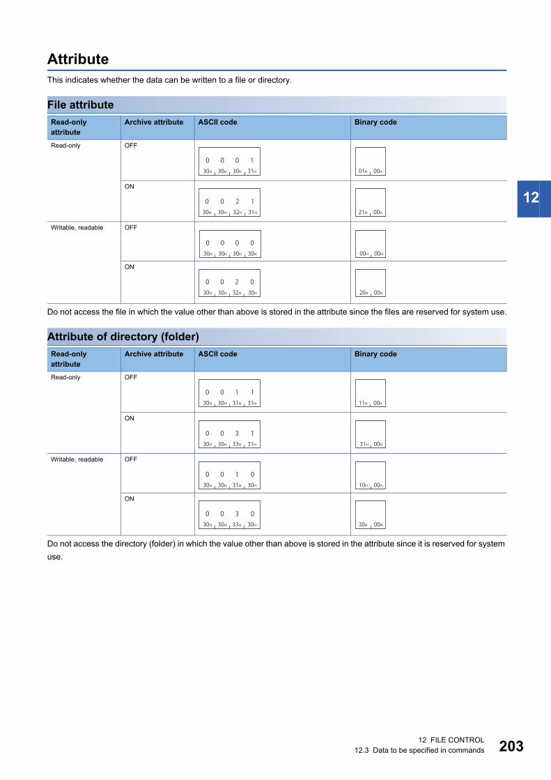
12 FILE CONTROL12.3 Data to be specified in commands 203
12
AttributeThis indicates whether the data can be written to a file or directory.
File attribute
Do not access the file in which the value other than above is stored in the attribute since the files are reserved for system use.
Attribute of directory (folder)
Do not access the directory (folder) in which the value other than above is stored in the attribute since it is reserved for system
use.
Read-only attribute
Archive attribute ASCII code Binary code
Read-only OFF
ON
Writable, readable OFF
ON
Read-only attribute
Archive attribute ASCII code Binary code
Read-only OFF
ON
Writable, readable OFF
ON
030H
030H
030H
131H 01H 00H
030H
030H
232H
131H 21H 00H
030H
030H
030H
030H 00H 00H
030H
030H
232H
030H 20H 00H
030H
030H 31H
1131H 11H 00H
030H
0 330H 33H
131H 31H 00H
030H
0 130H 31H
030H 10H 00H
030H
0 330H 33H
030H 30H 00H

20412 FILE CONTROL12.3 Data to be specified in commands
Creation date and time (last edit date and time)This is a date and time when the current file contents are registered.
Setting methodRepresent the date (year, month, day) and time (hour, minute, second) with 16-bit value, respectively.
■Data communication in ASCII codeConvert the respective numerical value to 4-digit ASCII code (hexadecimal) and send from the upper digits (time, year).
■Data communication in binary codeSend the respective 2-byte numerical value from the lower byte (L: bits 0 to 7).
Date (year, month, day)Represent the year, month, and day with 16-bit value.
• Year: The binary value is represented with bits 9 to 15 by setting the year 1980 to '0'. *1
• Month: The binary value is represented with bits 5 to 8.
• Day: The binary value is represented with bits 0 to 4.
*1 This indicates incremental number of year by regarding 1980 as '0'.
Ex.
For April 1, 2010
ASCII code Binary code
0 0 1 1 1 1 0 0 1 0 0 0 0 0 0 1b9 b8 b4 b0b5b15
1EH(30) 4H(4) 1H(1)
3H CH 8H 1H
(Year) (Month) (Day)
Numerical values in relevant range
30+1980 = 2010
Numerical values for 4 bits
333H
C43H
838H
131H 81H 3CH
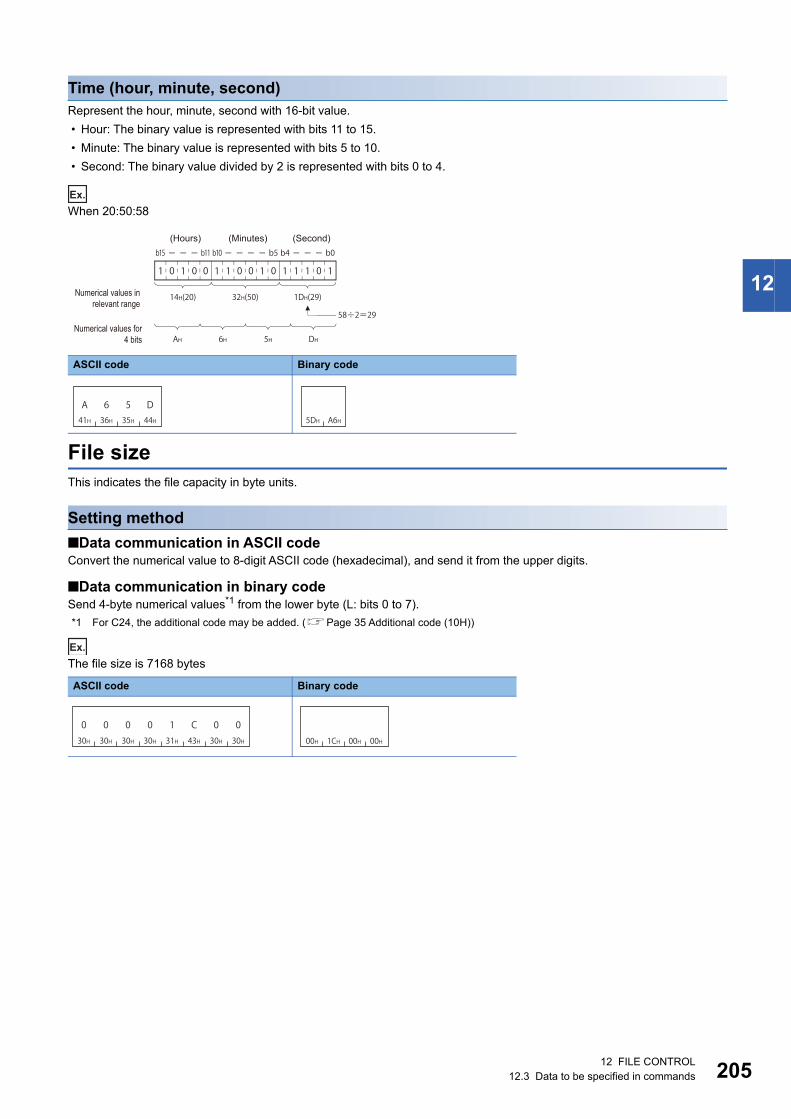
12 FILE CONTROL12.3 Data to be specified in commands 205
12
Time (hour, minute, second)Represent the hour, minute, second with 16-bit value.
• Hour: The binary value is represented with bits 11 to 15.
• Minute: The binary value is represented with bits 5 to 10.
• Second: The binary value divided by 2 is represented with bits 0 to 4.
Ex.
When 20:50:58
File sizeThis indicates the file capacity in byte units.
Setting method
■Data communication in ASCII codeConvert the numerical value to 8-digit ASCII code (hexadecimal), and send it from the upper digits.
■Data communication in binary codeSend 4-byte numerical values*1 from the lower byte (L: bits 0 to 7).
*1 For C24, the additional code may be added. (Page 35 Additional code (10H))
Ex.
The file size is 7168 bytes
ASCII code Binary code
ASCII code Binary code
AH 6H 5H DH
1 0 1 0 0 1 1 0 0 1 0 1 1 1 0 1
b4 b0b10 b5b15 b11
14H(20) 32H(50) 1DH(29)
58÷2=29
(Hours) (Minutes) (Second)
Numerical values in relevant range
Numerical values for 4 bits
A41H
636H
535H
D44H 5DH A6H
30H 30H 30H 30H 31H 43H 30H 30H
0 0 0 00 1 C 000H 1CH 00H 00H

20612 FILE CONTROL12.3 Data to be specified in commands
File pointer No.This is a number for CPU module to manage files.
The file pointer No. can be acquired with the following command.
Page 234 Open file (command: 1827)
Setting method
■Data communication in ASCII codeSend 4-byte*1 ASCII code data.
■Data communication in binary codeSend 2-byte*1 numerical value.
*1 For C24, the additional code may be added. (Page 35 Additional code (10H))
Ex.
For AH
Offset addressSpecify the address (one address/one byte) from the head (offset address: 0H) of each file with an even number.
Setting method
■Data communication in ASCII codeConvert the numerical value to 8-digit ASCII code (hexadecimal), and send it from the upper digits.
■Data communication in binary codeSend 4-byte numerical values*1 from the lower byte (L: bits 0 to 7).
*1 For C24, the additional code may be added. (Page 35 Additional code (10H))
Ex.
Offset address is 780H(1920)
ASCII code Binary code
ASCII code Binary code
030H
030H
030H
A3AH 0AH 00H
- 1
0
Offset address
Data
(File size)
030H
030H
030H
030H
0 7 8 030H 37H 38H 30H 80H 07H 00H 00H
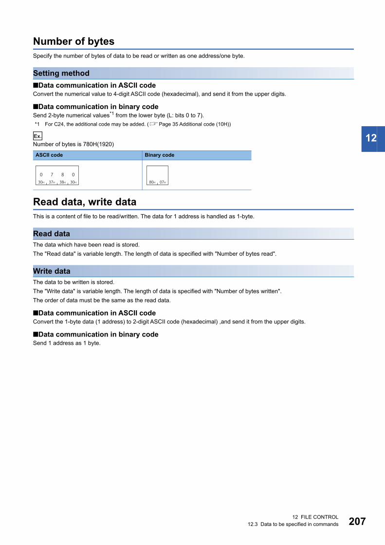
12 FILE CONTROL12.3 Data to be specified in commands 207
12
Number of bytesSpecify the number of bytes of data to be read or written as one address/one byte.
Setting method
■Data communication in ASCII codeConvert the numerical value to 4-digit ASCII code (hexadecimal), and send it from the upper digits.
■Data communication in binary codeSend 2-byte numerical values*1 from the lower byte (L: bits 0 to 7).
*1 For C24, the additional code may be added. (Page 35 Additional code (10H))
Ex.
Number of bytes is 780H(1920)
Read data, write dataThis is a content of file to be read/written. The data for 1 address is handled as 1-byte.
Read dataThe data which have been read is stored.
The "Read data" is variable length. The length of data is specified with "Number of bytes read".
Write dataThe data to be written is stored.
The "Write data" is variable length. The length of data is specified with "Number of bytes written".
The order of data must be the same as the read data.
■Data communication in ASCII codeConvert the 1-byte data (1 address) to 2-digit ASCII code (hexadecimal) ,and send it from the upper digits.
■Data communication in binary codeSend 1 address as 1 byte.
ASCII code Binary code
030H
737H
838H
030H 80H 07H

20812 FILE CONTROL12.3 Data to be specified in commands
Open modeSpecify whether the specified file is open for reading or for writing with the 'open file' (command: 1827).
Close typeSpecify a target to be closed with the 'close file' (command: 182A).
When all files are specified for unlock, the external device that executes the close (command: 182A) closes all files being
open regardless of the hierarchy of drive No. or directory (folder). (There is no difference between 0001H and 0002H.)
The files which were opened by the other devices cannot be closed.
Executing the command to files locked by the other external device results in abnormal completion of the command.
Files are closed by restarting a module (such as resetting CPU module).
Item ASCII code Binary code
For reading
For writing
File to unlock ASCII code Binary code
A file specified by the file pointer
All files
030H
030H
030H
030H 00H 00H
030H
131H
030H
030H 00H 01H
030H
030H
030H
030H 00H 00H
030H
030H
030H
131H 01H 00H
030H
030H
030H
232H 02H 00H
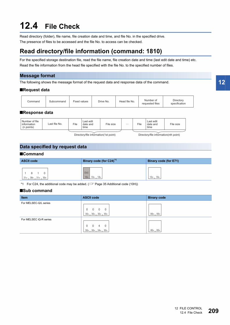
12 FILE CONTROL12.4 File Check 209
12
12.4 File CheckRead directory (folder), file name, file creation date and time, and file No. in the specified drive.
The presence of files to be accessed and the file No. to access can be checked.
Read directory/file information (command: 1810)For the specified storage destination file, read the file name, file creation date and time (last edit date and time) etc.
Read the file information from the head file specified with the file No. to the specified number of files.
Message formatThe following shows the message format of the request data and response data of the command.
■Request data
■Response data
Data specified by request data
■Command
*1 For C24, the additional code may be added. (Page 35 Additional code (10H))
■Sub command
ASCII code Binary code (for C24)*1 Binary code (for E71)
Item ASCII code Binary code
For MELSEC-Q/L series
For MELSEC iQ-R series
Head file No.Subcommand Fixed values Drive No. Directory specification
Command Number of requested files
Number of file information (n points)
Last file No. FileLast edit date and time
File size FileLast edit date and time
File size
Directory/file information(1st point) Directory/file information(nth point)
131H
838H
131H
030H 10H 18H10H
DLE
10H 18H
030H
030H
030H
030H 00H 00H
030H
030H
434H
030H 40H 00H

21012 FILE CONTROL12.4 File Check
■Fixed valueSpecify 30H in 4 bytes.
■Drive No.Specify the access target drive. (Page 196 Drive No.)
■Head file No.Specify the file No. of the file from which the file information is to be read. (Page 197 File No.)
File No. can be obtained by following command.
Page 215 Search directory/file information (command: 1811)
■Number of requested fileSpecify the number of files from which file information is read in the range of 1 to 36. (Page 198 Number of files)
■Directory specificationDepending on the access target, specify any of the following:
• MELSEC iQ-R series (when using subcommand '0040'): Specify the target folder with an absolute path. (Page 198
Directory specification)
• MELSEC-Q/L series (when using subcommand '0000'): Specify '0'.
When checking all files in the specified directory (folder), refer to the following section.
Page 188 Procedure to read information from all files in directory (folder)
Data stored in response data
■Number of file informationThe number of file information which has been read is stored. (Page 198 Number of files)
In the following situation, the number of file information will be fewer than the number of requested file.
• When using subcommand '0040', the data of "Number of requested file" cannot be stored at one communication because
the file name length is too long.
• When the number of files exist following the "Head file No." is less than the "Number of requested file".
When no files exist after the specified head file No., the following value is stored.
• MELSEC-Q/L series (when using subcommand '0000'): "Number of file information" = '0'
• MELSEC iQ-R series (when using subcommand '0040'): "Number of file information" = -1 (FFFFH)
■Last file No.The file No. of the last file from which file information was read is stored. (Page 197 File No.)
For MELSEC-Q/L series (subcommand '0000'), last file No. is not stored.
File No. is also assigned for the system-reserved data that cannot acquire the directory/file information,
therefore, the "Last file No." may differ from the file No. of the last file for the read file information.
Acquire the file No. using the following command.
Page 215 Search directory/file information (command: 1811)
Use "Last file No." in the following process.
Page 188 Procedure to read information from all files in directory (folder)
ASCII code, binary code
ASCII code Binary code
30H 30H 30H 30H
030H
030H
030H
030H 00H 00H

12 FILE CONTROL12.4 File Check 211
12
■Directory/file informationInformation for number of file information is stored.
When folders exist in the specified storage destination, the information for the folder is also read.
The information of the current directory (.) and the parent directory (..) are read at the same time.
The following items are stored for each file.
• File name specification: The file name is stored. The format differs depending on the subcommand. (Path name is not
included in the file name even when using the subcommand 0040.)
• Attribute: The file attributes are stored. (Page 203 Attribute)
• Last edit time, Last edit date: The last edit date and time are stored. (Page 204 Creation date and time (last edit date
and time))
• Spare data: The system data which are 18 or 4 bytes during data communication in ASCII code and 9 or 2 bytes*1 during
data communication in binary code are stored.
• File size: Capacity of file is stored in byte unit. (Page 205 File size)
*1 For C24, the additional code may be added. (Page 35 Additional code (10H))
For a folder, the following values will be stored.
• Attribute: Attribute of the directory (folder) is stored. (Page 203 Attribute of directory (folder))
• Last edit time, Last edit date: The folder creation date and time are stored.
• File size: '0' is stored.
Sub command Reference
For MELSEC-Q/L series
(Subcommand: 0000)
Page 200 File name of MELSEC-Q/L series module (File name and extension)
For MELSEC iQ-R series
(Subcommand:0040)
Page 202 File name of MELSEC iQ-R series module (Number of characters and file name)
Spare data ASCII: 18 bytes Binary: 9 bytes
Spare data ASCII: 4 bytes Binary: 2 bytes
File name specification Attribute Last edit time Last edit date File size
File Last edit date and time
File information (1 point)

21212 FILE CONTROL12.4 File Check
Communication example (files for MELSEC-Q/L series)Read directory/file information under the following conditions.
• Drive No.: 0
• Head file No.: 1
• Number of requested files: 3
■Data communication in ASCII code(Request data)
(Response data)
■Data communication in binary code(Request data)
(Response data)
1 8 1 031H 38H 31H 30H
0 0 0 030H 30H 30H 30H
0 0 0 030H 30H 30H 30H
0 0 0 030H 30H 30H 30H
0 0 0 130H 30H 30H 31H
0 0 0 330H 30H 30H 33H
0 0 0 030H 30H 30H 30H
Head file No.
Directory specification (Fixed values)Subcommand (Fixed value) Drive No. Number of
file requests
0 0 0 330H 30H 30H 33H
0 0 0 130H 30H 30H
A 6 541H 36H 35H
D44H
3 C 833H 43H 38H
131H
0 0 030H 30H 30H
0 0 430H 30H 34H
0 030H 30H
31HA B C D41H 42H 43H 44H
E F G H45H 46H 47H 48H
Q P G51H 50H 47H
Number of file information
Directory/ file information 1
Directory/ file information 2
Directory/ file information 3
File name Extension Attribute Spare data
Last edit time Last edit date Spare data File size
"20 h 58 m 58 s" "April 1, 2010" 1k byte
Last edit date and time
(18 bytes)
10H 18H 00H 00H 00H 00H 01H 00H 03H 00H30H 30H 30H 30H 00H 00H
Head file No.Subcommand
Drive No.
Number of file requests
Directory specification (Fixed values)(Fixed value)
03H 00H
A B C D41H 42H 43H 44H
E F G H45H 46H 47H 5DH A6H 81H 3CH 00H 04H 00H 00H48H
Q P G51H 50H 47H 01H 00H
Number of file information
Directory/ file information 1
Directory/ file information 2
Directory/ file information 3
Last edit time
Last edit dateFile name Extension Attribute Spare data Spare data File size
"20 h 58 m 58 s" "April 1, 2010" 1k byteFile
Last edit date and time
(9 bytes)

12 FILE CONTROL12.4 File Check 213
12
Communication example (files for MELSEC iQ-R series)Read directory/file information under the following conditions.
• Drive No.: 4
• Head file No.: 1
• Number of requested files: 3
The path names of directory are shown in the following table.
(1) SUBDIR (6 characters)
The following shows the file name of a directory/file information to be read.
The current directory information is stored in the directory/file information 1.
The parent directory information is stored in the directory/file information 2.
The following shows the file name of the directory/file information 3.
(2) LINE.CSV (8 characters)
■Data communication in ASCII code(Request data)
In the figure (1), set the value of "ASCII code" in the table of "Value of code corresponds to character" in "Path name".
Item Value of code corresponds to character
Path name S U B D I R
UTF-16 0053 0055 0042 0044 0049 0052
ASCII code 30303533 30303535 30303432 30303434 30303439 30303532
Binary code 5300 5500 4200 4400 4900 5200
Directory Number of file name characters
Character code
Current directory 1 File name .
UTF-16 002E
ASCII code 30303245
Binary code 2E00
Parent directory 2 File name . .
UTF-16 002E 002E
ASCII code 30303245 30303245
Binary code 2E00 2E00
Item Value of code corresponds to character
File name L I N E . C S V
UTF-16 004C 0049 004E 0045 002E 0043 0053 0056
ASCII code 30303443 30303439 30303445 30303435 30303245 30303433 30303533 30303536
Binary code 4C00 4900 4E00 4500 2E00 4300 5300 5600
131H
838H
131H
030H
030H
030H
434H
030H
030H
030H
030H
030H
030H
030H
030H
434H
030H
030H
030H
030H
030H
030H
030H
131H
030H
030H
030H
636H
030H
030H
030H
333H
(1)
Subcommand (Fixed value) Drive No. Head file No. Number of requested files
Number of characters Path name
Directory specification

21412 FILE CONTROL12.4 File Check
(Response data)
In the figure (2), set the value of "ASCII code" in the table of "Value of code corresponds to character" in "File name".
■Data communication in binary code(Request data)
In the figure (1), set the value of "Binary code" in the table of "Value of code corresponds to character" in "Path name".
(Response data)
In the figure (2), set the value of "Binary code" in the table of "Value of code corresponds to character" in "File name".
(2)
030H
030H
030H
333H
030H
030H
030H
838H
030H
030H
030H
131H
A41H
636H
535H
D44H
333H
C43H
838H
131H
030H
030H
030H
030H
030H
434H
030H
030H
030H
030H 30H
0 030H
030H
030H
030H
939H
Number of file information Last file No.
Directory/ file information 1
Directory/ file information 2
Directory/ file information 3
Number of charactersFile name Attribute Spare data
(18 bytes)
File
Last edit time Last edit date Spare data File size
"20 h 58 m 58 s" "April 1, 2010" 1k byte
Last edit date and time
10H 18H 40H 00H 04H 00H 01H 00H 03H 00H 06H 00H(1)
00H 00H30H 30H 30H 30H
Drive No.
Number of file requestsHead file No.
Number of characters Path name(Fixed value)
Directory specification
Subcommand
03H 00H
08H 00H(2)
01H 00H 5DH A6H 81H 3CH 00H 04H 00H 00H
09H 00H 00H 00H
Number of file information Last file No.
Directory/ file information 1
Directory/ file information 2
Directory/ file information 3
Last edit time
Last edit date
Spare data File size
Number of characters
File name Attribute Spare data
"20 h 58 m 58 s" "April 1, 2010"
1k byteFile
Last edit date and time
(9 bytes)

12 FILE CONTROL12.4 File Check 215
12
Search directory/file information (command: 1811)Read the file No. of the specified file.
The file No. indicates the registration number of a file when the file is written to the module.
Message formatThe following shows the message format of the request data and response data of the command.
■Request data
■Response dataFile No. is stored. (Page 197 File No.)
If the file with the specified name does not exist, the command completes abnormally.
Data specified by request data
■Command
■Sub command
■Fixed value 1Specify the following fixed value.
• MELSEC iQ-R series (when using subcommand '0040'): Specify '0'.
• MELSEC-Q/L series (when using subcommand '0000'): Specify 20H in 4 bytes.
■Drive No.Specify the access target drive. (Page 196 Drive No.)
ASCII code Binary code
Item ASCII code Binary code
For MELSEC-Q/L series
For MELSEC iQ-R series
ASCII code Binary code
ASCII code, binary code
Subcommand Fixed values 1 Drive No. File nameCommand Fixed values 2 Number of file name characters
131H
838H
131H
131H 11H 18H
030H
030H
030H
030H 00H 00H
030H
030H
434H
030H 40H 00H
030H
030H
030H
030H 00H 00H 00H 00H
20H 20H 20H 20H

21612 FILE CONTROL12.4 File Check
■Fixed value 2Specify '0'.
■Number of file name characters, file nameSpecify the file name of which file No. is to be read. (Page 200 File name specification)
Communication example (files for MELSEC-Q series)Read the file No. in the following conditions.
• Password: 4 spaces (code: 20H)
• Drive No.: 0
• File name: ABC.QPG (file No.6)
■Data communication in ASCII code(Request data)
(Response data)
■Data communication in binary code(Request data)
(Response data)
ASCII code Binary code
030H
030H
030H
030H 00H 00H
1 8 1 131H 38H 31H 31H
0 0 0 030H 30H 30H 30H
0 0 0 030H 30H 30H 30H 20H 20H 20H 20H
0 0 0 030H 30H 30H 30H
0 0 0 730H 30H 30H 37H
A B C41H 42H 43H
. Q P G2EH 51H 50H 47H
Number of file namecharactersSubcommand (Fixed value 1) Drive No. (Fixed value 2) File name
030H
030H
030H
636H
File No.
11H 18H 00H 00H 00H 00H 07H 00H00H 00H20H 20H 20H 20HA B C41H 42H 43H
. Q P G2EH 51H 50H 47H
Subcommand Number of file name characters
Drive No. (Fixed value 2) File name(Fixed value 1)
06H 00H
File No.
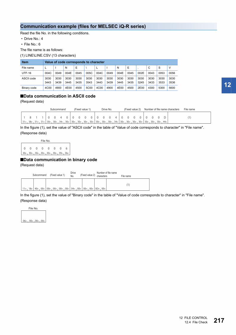
12 FILE CONTROL12.4 File Check 217
12
Communication example (files for MELSEC iQ-R series)Read the file No. in the following conditions.
• Drive No.: 4
• File No.: 6
The file name is as follows:
(1) LINE\LINE.CSV (13 characters)
■Data communication in ASCII code(Request data)
In the figure (1), set the value of "ASCII code" in the table of "Value of code corresponds to character" in "File name".
(Response data)
■Data communication in binary code(Request data)
In the figure (1), set the value of "Binary code" in the table of "Value of code corresponds to character" in "File name".
(Response data)
Item Value of code corresponds to character
File name L I N E \ L I N E . C S V
UTF-16 004C 0049 004E 0045 005C 004C 0049 004E 0045 002E 0043 0053 0056
ASCII code 3030
3443
3030
3439
3030
3445
3030
3435
3030
3543
3030
3443
3030
3439
3030
3445
3030
3435
3030
3245
3030
3433
3030
3533
3030
3536
Binary code 4C00 4900 4E00 4500 5C00 4C00 4900 4E00 4500 2E00 4300 5300 5600
1 8 1 131H 38H 31H 31H
0 0 0 030H 30H 30H 30H
0 0 4 0 0 0 0 030H 30H 34H 30H 30H 30H 30H 30H
0 0 0 430H 30H 30H 34H
0 0 0 D30H 30H 30H 44H
(1)
Subcommand Drive No. (Fixed value 2) Number of file name characters(Fixed value 1) File name
0 0 030H 30H 30H
030H
0 0 030H 30H 39H
6 36H
File No.
(1)11H 18H 40H 00H 00H 00H 0DH 00H04H 00H00H 00H 00H 00H
SubcommandDrive No.
Number of file name characters(Fixed value 1) (Fixed value 2) File name
00H06H 00H 00H
File No.

21812 FILE CONTROL12.5 File Creation and Deletion
12.5 File Creation and DeletionCreate a new file or delete a file.
Create new file (command: 1820)Specify the size to create a new file.
A folder cannot be created with this command. Create a folder with an Engineering tool.
The time on a module is registered as the last edit date and time in a file created using this function.
Message formatThe following shows the message format of the request data and response data of the command.
■Request data
■Response dataThere is no response data for this command.
Data specified by request data
■Command
■Sub command
■PasswordSpecify the following fixed value.
• MELSEC iQ-R series (when using subcommand '0040'): Specify '0'.
• MELSEC-Q/L series (when using subcommand '0000'): Specify 20H in 4 bytes.
ASCII code Binary code
Item ASCII code Binary code
For MELSEC-Q/L series
For MELSEC iQ-R series
ASCII code Binary code
ASCII code, binary code
Command Subcommand Password Drive No. File size Number of file name characters File name
131H
838H
232H
030H 20H 18H
030H
030H
030H
030H 00H 00H
030H
030H
434H
030H 40H 00H
030H
030H
030H
030H 00H 00H 00H 00H
20H 20H 20H 20H

12 FILE CONTROL12.5 File Creation and Deletion 219
12
■Drive No.Specify the access target drive. (Page 196 Drive No.)
■File sizeSpecify the file capacity in byte unit. (Page 205 File size)
■Number of file name characters, file nameSpecify the file name to be created. (Page 200 File name specification)
Communication example (files for MELSEC-Q series)Create a new file in the following conditions:
• Password: 4 spaces (code: 20H)
• Drive No.: 0
• File name: ABC.CSV
• File size: 1K byte
■Data communication in ASCII code(Request data)
■Data communication in binary code(Request data)
1 8 2 031H 38H 32H 30H
0 0 030H 30H 30H
030H 20H 20H 20H 20H
030H 30H 30H 30H 30H 30H 30H 30H 34H 30H 30H 30H
0 0 0 0 0 0 0 4 0 0 0
30H 30H 30H 37H 41H 42H 43H 2EH 43H 53H 56H
0 0 0 7 A B C . C S V
Subcommand Password Drive No. File size
Number of file name characters File name
20H 20H00H 00H20H 18H 20H 20H 00H 00H 00H 40H 00H 00H 07H 00H 41H 42H 43H 2EH 43H 53H 56HA B C . C S V
Number of file name charactersSubcommand File namePassword Drive No. File size

22012 FILE CONTROL12.5 File Creation and Deletion
Communication example (files for MELSEC iQ-R series)Create a new file in the following conditions:
• Drive No.: 4
• File size: 7168 byte
• File name: LINE.CSV (8 characters)
The value of the file name is as follows:
(1) LINE.CSV (8 characters)
■Data communication in ASCII code(Request data)
In the figure (1), set the value of "ASCII code" in the table of "Value of code corresponds to character" in "File name".
■Data communication in binary code(Request data)
In the figure (1), set the value of "Binary code" in the table of "Value of code corresponds to character" in "File name".
Item Value of code corresponds to character
File name L I N E . C S V
UTF-16 004C 0049 004E 0045 002E 0043 0053 0056
ASCII code 30303443 30303439 30303445 30303435 30303245 30303433 30303533 30303536
Binary code 4C00 4900 4E00 4500 2E00 4300 5300 5600
1 8 2 031H 38H 32H 30H
0 0 4 030H 30H 34H 30H 30H 30H 30H 30H
0 0 0 430H 30H 30H 34H
0 0 0 0 1 C0 0 0 030H 30H 30H 30H
0 031H 43H 30H 30H
0 0 0 830H 30H 30H 38H
(1)
Number of file namecharactersSubcommand (Fixed value) Drive No. File size File name
20H 18H 40H 00H 00H 00H 00H 00H 00H 1CH 00H 00H04H 00H 08H 00H(1)
Drive No.
Number of file name charactersSubcommand File size File name

12 FILE CONTROL12.5 File Creation and Deletion 221
12
Delete file (command: 1822)Delete a file.
If files are deleted while a programmable controller system is in operation, the system may be stopped.
Determine the timing of file deletion for the entire programmable controller system.
• The files on which the 'open file' command is being executed cannot be deleted. Close the file before
deleting it. (Page 234 Open file (command: 1827), Page 242 Close file (command: 182A))
• The file being executed cannot be deleted when CPU module is state of RUN. Delete the file after placing
CPU module to the STOP state. (Page 462 Applicable Commands for Online Program Change)
Message formatThe following shows the message format of the request data and response data of the command.
■Request data
■Response dataThere is no response data for this command.
Data specified by request data
■Command
■Sub command
■PasswordSpecify the password of the file. (Page 193 Password)
■Drive No.Specify the access target drive. (Page 196 Drive No.)
ASCII code Binary code
Item ASCII code Binary code
For MELSEC-Q series
For MELSEC-L series
For MELSEC iQ-R series
Command Subcommand Password Drive No. Number of file name characters
File name
131H
838H
232H
232H 22H 18H
030H
030H
030H
030H 00H 00H
030H
030H
030H
434H 04H 00H
030H
030H
434H
030H 40H 00H

22212 FILE CONTROL12.5 File Creation and Deletion
■Number of file name characters, file nameSpecify the file name to be deleted. (Page 200 File name specification)
Communication example (files for MELSEC-Q series)Delete the file under the following conditions:
• Password: 1234
• Drive No.: 0
• File name: ABC.QPG
■Data communication in ASCII code(Request data)
■Data communication in binary code(Request data)
Communication example (files for MELSEC-L series)Delete the file under the following conditions:
• Password: AbCd1234... (24 spaces, code: 20H)
• Drive No.: 0
• File name: MAIN.QPG
■Data communication in ASCII code(Request data)
■Data communication in binary code(Request data)
1 8 2 2 0 0 0 031H 32H 33H 34H30H 30H 30H 30H31H 38H 32H 32H
030H 30H 30H 30H
0 0 01 2 3 430H 30H 30H 37H 41H 42H 43H 2EH 51H 50H 47H
0 0 0 7 A B C . Q P G
Subcommand Password Drive No. Number of file name characters File name
31H 32H 33H 34H22H 18H 00H 00H 07H 00H 41H 42H 2EH 51H 50H 47H43H00H 00H1 2 3 4 A B C . Q P G
Number of file name charactersSubcommand Drive No.Password File name
1 8 2 2 0 0 0 441H 62H 43H 64H30H 30H 30H 34H31H 38H 32H 32H 31H 32H 33H 34H 20H 20H 30H 30H 30H 30H
0 0 0 0
30H 30H 30H 38H 4DH 41H 49H 2EH 51H 50H 47H
0 0 0 8 M A I4EH
N . Q P G
A b C d 1 2 3 4
Subcommand Password (fixed to 32 characters) Drive No.
Number of file name characters File name
41H 62H 43H 64H22H 18H 04H 00H 31H 32H 33H 34H 20H 20H 08H 00H 4DH 41H 49H 2EH 51H 50H 47H4EH00H 00HA b C d 1 2 3 4 M A I N . Q P G
Number of file name charactersSubcommand Drive No.Password File name

12 FILE CONTROL12.5 File Creation and Deletion 223
12
Communication example (files for MELSEC iQ-R series)Delete the file under the following conditions:
• Password: A to Z (26 characters)
• Drive No.: 4
The file name is as follows:
(1) LINE.CSV (8 characters)
■Data communication in ASCII code(Request data)
In the figure (1), set the value of "ASCII code" in the table of "Value of code corresponds to character" in "File name".
■Data communication in binary code(Request data)
In the figure (1), set the value of "Binary code" in the table of "Value of code corresponds to character" in "File name".
Item Value of code corresponds to character
File name L I N E . C S V
UTF-16 004C 0049 004E 0045 002E 0043 0053 0056
ASCII code 30303443 30303439 30303445 30303435 30303245 30303433 30303533 30303536
Binary code 4C00 4900 4E00 4500 2E00 4300 5300 5600
1 8 2 231H 38H 32H 32H
0 0 4 030H 30H 34H 30H
0 0 1 A30H 30H 31H 41H
C D Z43H 44H 54H
A B41H 42H
0 0 0 430H 30H 30H 34H
0 0 0 830H 30H 30H 38H
(1)
Number of password charactersSubcommand Password
Number of file namecharactersDrive No. File name
22H 18H 40H 00H 04H 00H 0DH 00HC D Z43H 44H 5AH
A B1AH 00H 41H 42H
(1)
SubcommandNumber of password characters
Drive No.
Number of file name charactersPassword File name

22412 FILE CONTROL12.5 File Creation and Deletion
Copy file (command: 1824)Copy a file.
When this command is executed to files of parameter and a program being executed, place CPU module in
the STOP status. (Page 462 Commands that cannot be executed during RUN)
Message formatThe following shows the message format of the request data and response data of the command.
■Request data
■Response dataThere is no response data for this command.
Data specified by request data
■Command
■Sub command
■Fixed valueSpecify '0'.
ASCII code Binary code
Item ASCII code Binary code
For MELSEC-Q series
For MELSEC-L series
For MELSEC iQ-R series
ASCII code Binary code
Password Drive No. Number of file name characters
File nameCommand Subcommand Fixed values
Copy destination
Password Drive No. Number of file name characters File name
Copy source
131H
838H
232H
434H 24H 18H
030H
030H
030H
030H 00H 00H
030H
030H
030H
434H 04H 00H
030H
030H
434H
030H 40H 00H
30H 30H 30H 30H 30H(16 characters)
00H 00H 00H 00H 00H(8 bytes)

12 FILE CONTROL12.5 File Creation and Deletion 225
12
■PasswordSpecify the password of the access target file. (Page 193 Password)
■Drive No.Specify the access target drive. (Page 196 Drive No.)
Program memory (drive No.0) of RCPU cannot be specified.
■Number of file name characters, file nameSpecify the file name to be copied. (Page 200 File name specification)
Communication example (files for MELSEC-Q series)Copy the file under the following conditions:
• Copy source/destination password: 1234
• Drive No. of copy source, drive No. of copy destination: 0
• Copy source file name: ABC.QPG
• Copy source file name: CBA.QPG
■Data communication in ASCII code(Request data)
■Data communication in binary code(Request data)
1 8 2 4 0 0 0 031H 38H 32H 34H 30H 30H 30H 30H 30H 30H 30H 30H
1 2 3 4 0 0 0 0 0 0 0 7 C B A . Q P G31H 32H 33H 34H 30H 30H 30H 30H 30H 30H 30H 37H 43H 42H 41H 2EH 51H 50H 47H
1 2 3 4 0 0 0 0 0 0 0 7 A B C . Q P G31H 32H 33H 34H 30H 30H 30H 30H 30H 30H 30H 37H 41H 42H 43H 2EH 51H 50H 47H
0 0 0 0…
Subcommand Fixed values (16 characters) Password Drive No. Number of file name characters File name
Copy destination
Password Drive No. Number of file name characters File name
Copy source
24H 18H 00H 00H 00H 00H 00H 00H 00H 00H 00H 00H 31H 32H 33H 34H 00H 00H 07H 00H 43H 42H 41H 2EH 51H 50H 47H
31H 32H 33H 34H 00H 00H 07H 00H 41H 42H 43H 2EH 51H 50H 47H
1 2 3 4 C B A . Q P G
1 2 3 4 A B C . Q P G
Number of file name charactersFixed values (8 bytes) Password File nameDrive No.
Copy destination
Number of file name charactersPassword Drive No. File name
Copy source
Subcommand

22612 FILE CONTROL12.5 File Creation and Deletion
Communication example (files for MELSEC-L series)Copy the file under the following conditions:
• Password copy source/destination AbCd1234... (24 spaces, code: 20H)
• Drive No. of copy source, drive No. of copy destination: 0
• Copy source file name: MAIN.QPG
• Copy source file name: DEST.QPG
■Data communication in ASCII code(Request data)
■Data communication in binary code(Request data)
1 8 2 4 0 0 0 431H 38H 32H 34H 30H 30H 30H 34H 30H 30H 30H 30H
0 0 0 0 0 0 0 8 D E S . Q P G41H 62H 43H 64H 31H 32H 33H 34H 20H 20H
41H 62H 43H 64H 31H 32H 33H 34H 20H 20H
30H 30H 30H 30H 30H 30H 30H 38H 44H 45H 53H 2EH 51H 50H 47H
0 0 0 0 0 0 0 8 M A I . Q P G30H 30H 30H 30H 30H 30H 30H 38H 4DH 41H 49H
T54H
N4EH 2EH 51H 50H 47H
A b C d 1 2 3 4
A b C d 1 2 3 4
0 0 0 0
Subcommand Fixed values (16 characters)
Password (fixed to 32 characters) Drive No.Number of file name characters File name
Copy destination
Password (fixed to 32 characters) Drive No.Number of file name characters File name
Copy source
24H 18H 04H 00H 00H 00H 00H 00H 00H 00H 00H 00H
41H 62H 43H 64H 31H 32H 33H 34H 20H 20H
41H 62H 43H 64H 31H 32H 33H 34H 20H 20H
00H 00H 08H 00H 44H 45H 53H 2EH 51H 50H 47H
00H 00H 08H 00H 4DH 41H 49H
54H
4EH 2EH 51H 50H 47H
D E S . Q P G
M A I . Q P G
T
N
A b C d 1 2 3 4
A b C d 1 2 3 4
Subcommand Fixed values (8 bytes)
Number of file name charactersPassword (fixed to 32 characters) File name
Copy destination Drive No.
Number of file name charactersCopy source Password (fixed to 32 characters) File nameDrive No.
Copy source
Copy destination

12 FILE CONTROL12.5 File Creation and Deletion 227
12
Communication example (files for MELSEC iQ-R series)Copy the file under the following conditions:
• Drive No. of copy source: 2
• Drive No. of copy destination: 4
The file name of the copy source and copy destination is as follows.
(1) LINE.CSV (8 characters)
■Data communication in ASCII code(Request data)
In the figure (1), set the value of "ASCII code" in the table of "Value of code corresponds to character" in "File name".
■Data communication in binary code(Request data)
In the figure (1), set the value of "Binary code" in the table of "Value of code corresponds to character" in "File name".
Item Value of code corresponds to character
File name L I N E . C S V
UTF-16 004C 0049 004E 0045 002E 0043 0053 0056
ASCII code 30303443 30303439 30303445 30303435 30303245 30303433 30303533 30303536
Binary code 4C00 4900 4E00 4500 2E00 4300 5300 5600
1 8 2 431H 38H 32H 34H
0 0 4 030H 30H 34H 30H
0 0 0 030H 30H 30H 30H
0 0 0 030H 30H 30H 30H
0 0 0 030H 30H 30H 30H
0 0 0 030H 30H 30H 30H
0 0 0 430H 30H 30H 34H
0 0 0 830H 30H 30H 38H
C D Z43H 44H 54H
A B41H 42H
0 0 0 230H 30H 30H 32H
C D Z43H 44H 54H
A B41H 42H
0 0 0 830H 30H 30H 38H
(1)
(1)
0 0 1 A30H 30H 31H 41H
0 0 1 A30H 30H 31H 41H
Fixed values (16 characters)Subcommand
Number of copy destination password characters
Copy destination password
Copy destination drive No.
Number of copy destination file name characters
Copy destination file name
Number of copy source password characters
Copy source password
Copy source drive No.
Number of copy source file name characters
Copy source file name
(1)
(1)24H 18H 00H 00H04H 00H 00H 00H 00H 00H 00H 00H 04H 00H 08H 00H
C D … Z43H 44H 5AH
A B1AH 00H 41H 42H 02H 00H 08H 00H
C D … Z43H 44H 54H
A B1AH 00H 41H 42H
Number ofcopy destinationpassword characters
Copy destinationdrive No.
Number of copy destinationfile name charactersSubcommand
Copy destinationpassword Copy destination file nameFixed values (8 bytes)
Number of copy sourcepassword characters
Copy sourcedrive No.
Number of copy source file name charactersCopy source password Copy source file name

22812 FILE CONTROL12.6 File Modification
12.6 File ModificationRead or write data from/to the specified file. Lock the file with the open/close file command during reading or writing so that
the file contents will not be changed from other devices. The file is not required to be locked with the open file command when
commands other than read/write file command are executed.
When modifying the file attributes and the last edit date and time, executing the open command is not required.
Modify file attribute (command: 1825)Change the file attributes (read only/writable).
When this command is executed to files of parameter and a program being executed, place CPU module in
the STOP status. (Page 462 Commands that cannot be executed during RUN)
Message formatThe following shows the message format of the request data and response data of the command.
■Request data
■Response dataThere is no response data for this command.
Data specified by request data
■Command
■Sub command
■PasswordSpecify the password of the access target file. (Page 193 Password)
ASCII code Binary code
Item ASCII code Binary code
For MELSEC-Q series
For MELSEC-L series
For MELSEC iQ-R series
Command Subcommand Password Drive No. Attribute Number of file name characters File name
131H
838H
232H
535H 25H 18H
030H
030H
030H
030H 00H 00H
030H
030H
030H
434H 04H 00H
030H
030H
434H
030H 40H 00H
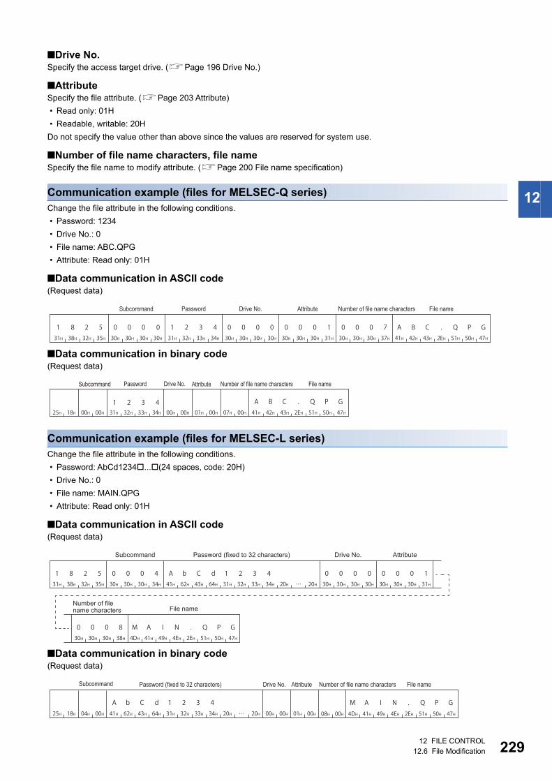
12 FILE CONTROL12.6 File Modification 229
12
■Drive No.Specify the access target drive. (Page 196 Drive No.)
■AttributeSpecify the file attribute. (Page 203 Attribute)
• Read only: 01H
• Readable, writable: 20H
Do not specify the value other than above since the values are reserved for system use.
■Number of file name characters, file nameSpecify the file name to modify attribute. (Page 200 File name specification)
Communication example (files for MELSEC-Q series)Change the file attribute in the following conditions.
• Password: 1234
• Drive No.: 0
• File name: ABC.QPG
• Attribute: Read only: 01H
■Data communication in ASCII code(Request data)
■Data communication in binary code(Request data)
Communication example (files for MELSEC-L series)Change the file attribute in the following conditions.
• Password: AbCd1234...(24 spaces, code: 20H)
• Drive No.: 0
• File name: MAIN.QPG
• Attribute: Read only: 01H
■Data communication in ASCII code(Request data)
■Data communication in binary code(Request data)
1 8 2 531H 38H 32H 35H
0 0 030H 30H 30H
030H 31H 32H 33H 34H
030H 30H 30H 30H 30H 30H 30H 31H
0 0 0 0 0 0 11 2 3 430H 30H 30H 37H 41H 42H 43H 2EH 51H 50H 47H
0 0 0 7 A B C . Q P G
Subcommand Password Drive No. Attribute Number of file name characters File name
31H 32H00H 00H25H 18H 33H 34H 00H 00H 01H 00H 07H 00H 41H 42H 43H 2EH 51H 50H 47H1 2 3 4 A B C . Q P G
File namePassword Drive No. AttributeSubcommand Number of file name characters
1 8 2 5 0 0 0 441H 62H 43H 64H30H 30H 30H 34H31H 38H 32H 35H 31H 32H 33H 34H 20H 20H 30H 30H 30H 30H
0 0 0 030H 30H 30H 31H
0 0 0 1
30H 30H 30H 38H 4DH 41H 49H 2EH 51H 50H 47H
0 0 0 8 M A I4EH
N . Q P G
A b C d 1 2 3 4
Subcommand Password (fixed to 32 characters) Drive No. Attribute
Number of file name characters File name
41H 62H 43H 64H25H 18H 04H 00H 31H 32H 33H 34H 20H 20H 08H 00H 4DH 41H 49H 2EH 51H 50H 47H4EH00H 00H 01H 00H
M A I N . Q P GA b C d 1 2 3 4
Subcommand AttributePassword (fixed to 32 characters) File nameDrive No. Number of file name characters
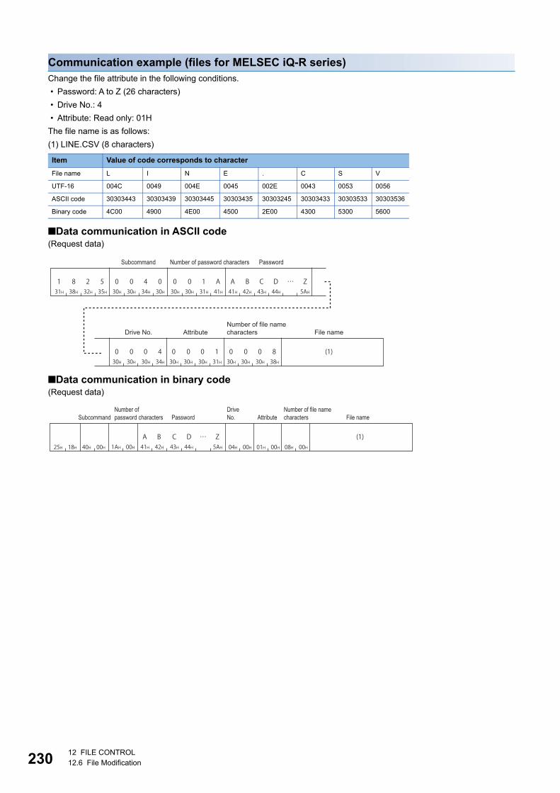
23012 FILE CONTROL12.6 File Modification
Communication example (files for MELSEC iQ-R series)Change the file attribute in the following conditions.
• Password: A to Z (26 characters)
• Drive No.: 4
• Attribute: Read only: 01H
The file name is as follows:
(1) LINE.CSV (8 characters)
■Data communication in ASCII code(Request data)
■Data communication in binary code(Request data)
Item Value of code corresponds to character
File name L I N E . C S V
UTF-16 004C 0049 004E 0045 002E 0043 0053 0056
ASCII code 30303443 30303439 30303445 30303435 30303245 30303433 30303533 30303536
Binary code 4C00 4900 4E00 4500 2E00 4300 5300 5600
1 8 2 531H 38H 32H 35H
0 0 4 030H 30H 34H 30H
A B C D41H 42H 43H 44H
0 0 1 A30H 30H 31H 41H
Z5AH
0 0 0 430H 30H 30H 34H
0 0 0 130H 30H 30H 31H
0 0 0 830H 30H 30H 38H
(1)
Subcommand Number of password characters Password
Number of file name charactersDrive No. Attribute File name
(1)25H 18H 40H 00H 04H 00H 01H 00H 08H 00H
C D Z43H 44H 5AH
A B1AH 00H 41H 42H
SubcommandNumber of password characters
Drive No.
Number of file name charactersPassword Attribute File name

12 FILE CONTROL12.6 File Modification 231
12
Modify file creation date and time (command: 1826)Modify the file creation date and time.
When this command is executed to files of parameter and a program being executed, place CPU module in
the STOP status. (Page 462 Commands that cannot be executed during RUN)
Message formatThe following shows the message format of the request data and response data of the command.
■Request data
■Response dataThere is no response data for this command.
Data specified by request data
■Command
■Sub command
■Fixed valueSpecify '0'.
■Drive No.Specify the access target drive. (Page 196 Drive No.)
■Date to change, time to changeThe file of the last edit date and time is modified with the specified date and time. (Page 204 Creation date and time (last
edit date and time))
■Number of file name characters, file nameSpecify the file name to modify attribute. (Page 200 File name specification)
ASCII code Binary code
Item ASCII code Binary code
For MELSEC-Q/L series
For MELSEC iQ-R series
ASCII code Binary code
Subcommand Fixed values Drive No. Date to
changeTime to change
Number of file name characters File nameCommand
131H
838H
232H
636H 26H 18H
030H
030H
030H
030H 00H 00H
030H
030H
434H
030H 40H 00H
030H
030H
030H
030H 00H 00H 00H 00H

23212 FILE CONTROL12.6 File Modification
Communication example (files for MELSEC-Q series)Modify the date and time of file creation under the following conditions.
• Drive No.: 0
• Date to change: 2010/04/01
• Time to change: 20:50:58
• File name: ABC.QPG
■Data communication in ASCII code(Request data)
■Data communication in binary code(Request data)
1 8 2 631H 38H 32H 36H
0 0 0 030H 30H 30H 30H
0 0 0 030H 30H 30H 30H
0 0 0 730H 30H 30H 37H
3 C 8 133H 43H 38H 31H
A 6 5 D41H 36H 35H 44H
0 0 0 030H 30H 30H 30H
A B C41H 42H 43H
. Q P G2EH 51H 50H 47H
Subcommand (Fixed value) Drive No. Date to change Time to change
Number of file name characters File name
26H 18H 00H 00H00H 00H 00H 00H 00H 00H 81H 3CH 5DH A6H 07H 00HA B C41H 42H 43H
. Q P G2EH 51H 50H 47H
SubcommandTime to change
Date to change
Number of file name characters
Drive No.(Fixed value) File name
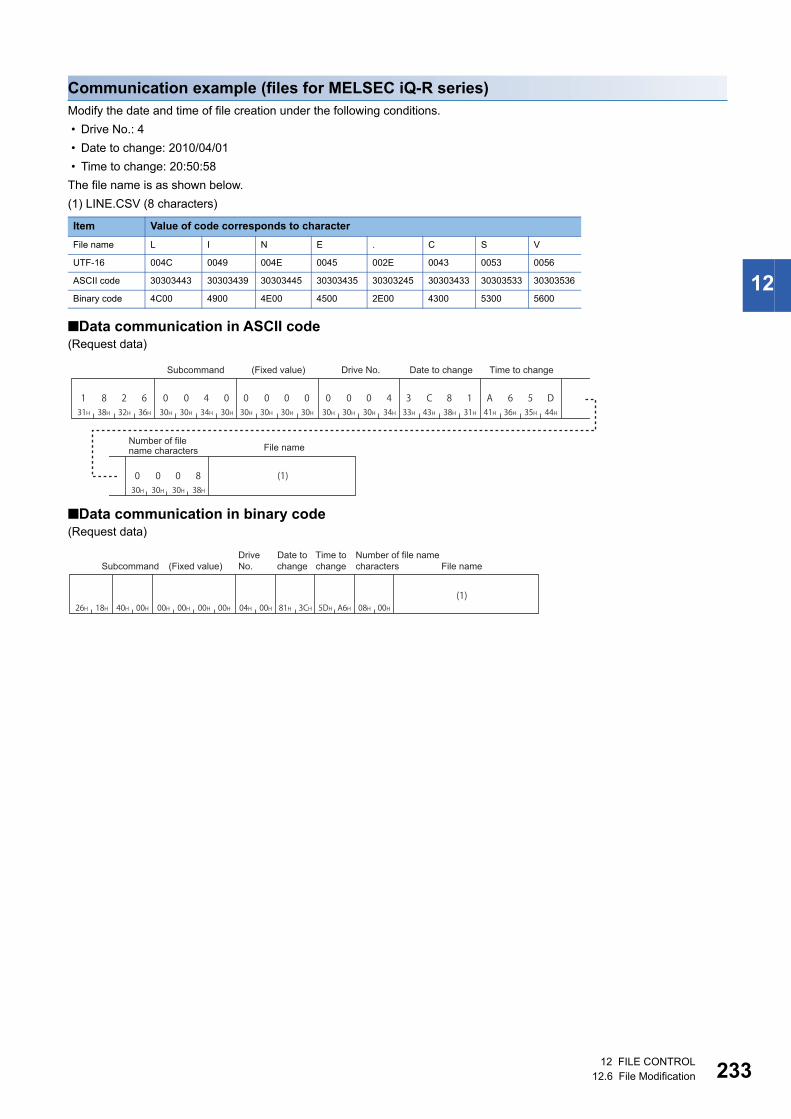
12 FILE CONTROL12.6 File Modification 233
12
Communication example (files for MELSEC iQ-R series)Modify the date and time of file creation under the following conditions.
• Drive No.: 4
• Date to change: 2010/04/01
• Time to change: 20:50:58
The file name is as shown below.
(1) LINE.CSV (8 characters)
■Data communication in ASCII code(Request data)
■Data communication in binary code(Request data)
Item Value of code corresponds to character
File name L I N E . C S V
UTF-16 004C 0049 004E 0045 002E 0043 0053 0056
ASCII code 30303443 30303439 30303445 30303435 30303245 30303433 30303533 30303536
Binary code 4C00 4900 4E00 4500 2E00 4300 5300 5600
1 8 2 631H 38H 32H 36H
0 0 0 030H 30H 30H 30H
0 0 0 430H 30H 30H 34H
0 0 0 830H 30H 30H 38H
3 C 8 133H 43H 38H 31H
A 6 5 D41H 36H 35H 44H
0 0 4 030H 30H 34H 30H
(1)
Date to change Time to changeSubcommand (Fixed value) Drive No.
Number of file name characters File name
26H 18H 00H 00H40H 00H 00H 00H 04H 00H 81H 3CH 5DH A6H 08H 00H(1)
SubcommandDrive No.
Date to change
Time to change
Number of file name characters(Fixed value) File name

23412 FILE CONTROL12.6 File Modification
Open file (command: 1827)Open a file and lock the file so that the file contents are not modified from other devices.
The file is unlocked by any of the following.
• Close file (command: 182A)
• Restarting a module. (Resetting the CPU module, etc.)
Message formatThe following shows the message format of the request data and response data of the command.
■Request data
■Response dataThe file pointer No. is stored. (Page 206 File pointer No.)
Data specified by request data
■Command
■Sub command
■PasswordSpecify the password of the access target file. (Page 193 Password)
■Open modeSpecify whether the specified file is open for reading or for writing. (Page 208 Open mode)
• Open for read: 0000H
• Open for write: 0100H
ASCII code Binary code
Item ASCII code Binary code
For MELSEC-Q series
For MELSEC-L series
For MELSEC iQ-R series
Command Subcommand Password Open mode Drive No. Number of file name characters File name
131H
838H
232H
737H 27H 18H
030H
030H
030H
030H 00H 00H
030H
030H
030H
434H 04H 00H
030H
030H
434H
030H 40H 00H

12 FILE CONTROL12.6 File Modification 235
12
■Drive No.Specify the access target drive. (Page 196 Drive No.)
■Number of file name characters, file nameSpecify the file name to be open. (Page 200 File name specification)
Communication example (files for MELSEC-Q series)Open the file of QCPU in the following conditions.
• Password: 1234
• Drive No.: 0
• File name: ABC.QPG
• Open mode: Open for write
■Data communication in ASCII code(Request data)
(Response data)
■Data communication in binary code(Request data)
(Response data)
1 8 2 731H 38H 32H 37H
0 0 030H 30H 30H
030H 31H 32H 33H 34H
030H 31H 30H 30H 30H 30H 30H 30H
1 0 0 0 0 0 01 2 3 430H 30H 30H 37H 41H 42H 43H 2EH 51H 50H 47H
0 0 0 7 A B C . Q P G
Number of file name characters File nameSubcommand Password Open mode Drive No.
0 0 0 030H 30H 30H 30H
File pointer No.
27H 18H 00H 00H 31H 32H 33H 34H 00H 01H 00H 00H 07H 00H 41H 42H 43H 2EH 51H 50H 47H1 2 3 4 A B C . Q P G
Drive No.
Subcommand File namePasswordNumber of file name charactersOpen mode
00H 00H
File pointer No.

23612 FILE CONTROL12.6 File Modification
Communication example (files for MELSEC-L series)Open the file of LCPU in the following condition.
• Password: AbCd1234... (24 spaces, code: 20H)
• Drive No.: 0
• File name: MAIN.QPG
• Open mode: Open for write
■Data communication in ASCII code(Request data)
(Response data)
■Data communication in binary code(Request data)
(Response data)
1 8 2 7 0 0 0 441H 62H 43H 64H30H 30H 30H 34H31H 38H 32H 37H 31H 32H 33H 34H 20H 20H 30H 30H 30H 30H
0 0 0 030H 31H 30H 30H
0 1 0 0
30H 30H 30H 38H 4DH 41H 49H 2EH 51H 50H 47H
0 0 0 8 M A I4EH
N . Q P G
A b C d 1 2 3 4
Subcommand Password (fixed to 32 characters) Open mode Drive No.
Number of file name characters File name
0 0 0 030H 30H 30H 30H
File pointer No.
41H 62H 43H 64H27H 18H 04H 00H 31H 32H 33H 34H 20H 20H 08H 00H 4DH 41H 49H 51H 50H 47H4EH00H 01H 00H 00H
A b C d 1 2 3 4 M A I N . Q P G2EH
Drive No.Subcommand Password (fixed to 32 characters)
Number of file name characters File nameOpen mode
00H 00H
File pointer No.

12 FILE CONTROL12.6 File Modification 237
12
Communication example (files for MELSEC iQ-R series)Open a file of MELSEC iQ-R series CPU module.
• Password: A to Z (26 characters)
• Drive No.: 4
• Open mode: Open for write
The file name is as follows:
(1) LINE.CSV (8 characters)
■Data communication in ASCII code(Request data)
(Response data)
■Data communication in binary code(Request data)
(Response data)
Item Value of code corresponds to character
File name L I N E . C S V
UTF-16 004C 0049 004E 0045 002E 0043 0053 0056
ASCII code 30303443 30303439 30303445 30303435 30303245 30303433 30303533 30303536
Binary code 4C00 4900 4E00 4500 2E00 4300 5300 5600
1 8 2 731H 38H 32H 37H
0 0 4 030H 30H 34H 30H
A B C D41H 42H 43H 44H
… Z5AH
0 0 1 A30H 30H 31H 41H
0 1 0 030H 31H 30H 30H
0 0 0 430H 30H 30H 34H
0 0 0 830H 30H 30H 38H
(1)
Subcommand Number of password characters Password
Number of file name charactersOpen mode Drive No. File name
0 0 0 030H 30H 30H 30H
File pointer No.
27H 18H 40H 00H 00H 01H 04H 00H 08H 00HC D Z43H 44H 34H
A B1AH 00H 41H 42H
(1)
SubcommandNumber of password characters
Openmode
Drive No.
Number of file name charactersPassword File name
00H 00H
File pointer No.

23812 FILE CONTROL12.6 File Modification
Read file (command: 1828)Read the content of a file.
Use the open/close command in order to prohibit access from other devices when this command is used.
Message formatThe following shows the message format of the request data and response data of the command.
■Request data
■Response dataThe data which have been read is stored.
Data specified by request data
■Command
■Sub command
■File pointer No.Specify the file pointer No. obtained with the 'open file' (command: 1827). (Page 206 File pointer No.)
■Offset addressSpecify the start address to start reading. (Page 206 Offset address)
■Number of bytes readSpecify the number of bytes to be read from file in the range of 0 to 1920. (Page 207 Number of bytes)
Specify it as one address/one byte.
When the file size is 1921 bytes or more, use an offset address and read data divide into multiple steps. The
file size can be checked by reading directory/file information (command: 1810).
Page 209 Read directory/file information (command: 1810)
Data stored in response data
■Number of bytes readThe number of data bytes read from file is stored. (Page 207 Number of bytes)
■Read dataThe contents of the read file are stored.
ASCII code Binary code
ASCII code Binary code
Command Subcommand File pointer No. Offset address Number of bytes read
Number of bytes read
Read data
131H
838H
232H
838H 28H 18H
030H
030H
030H
030H 00H 00H

12 FILE CONTROL12.6 File Modification 239
12
Communication exampleRead the file under the following conditions:
• File pointer No.: 0
• Number of bytes read: 1K bytes
■Data communication in ASCII code(Request data)
(Response data)
■Data communication in binary code(Request data)
(Response data)
1 8 2 831H 38H 32H 38H
0 0 030H 30H 30H
030H 30H 30H 30H 30H
030H 30H 30H 30H 30H 30H 30H 30H
0 0 0 0 0 0 00 0 0 030H 34H 30H 30H
0 4 0 0
Number of bytes readSubcommand File pointer No. Offset address
0 4 0 030H 34H 30H 30H
Number of bytes read Read data
(Contents of a file)
28H 18H 00H 00H 00H 00H 00H 00H 00H 00H 00H 04H
SubcommandFile pointer No. Number of
bytes readOffset address
00H 04H
Number of bytes read Read data
(Contents of a file)
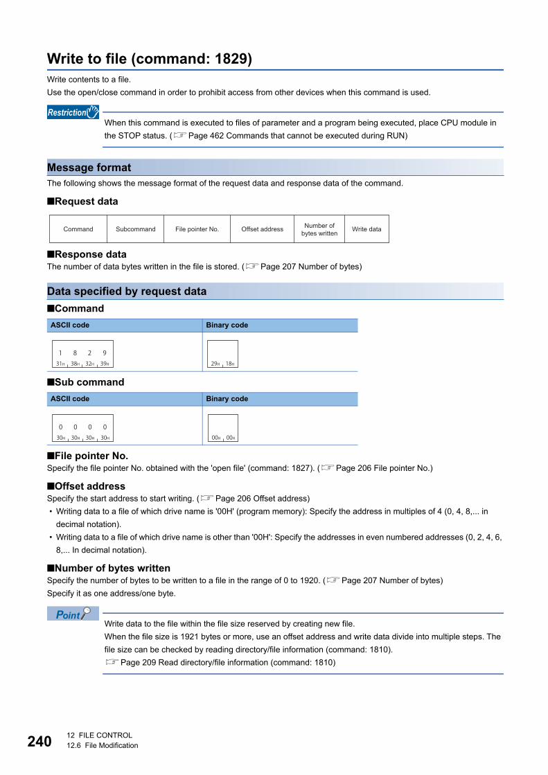
24012 FILE CONTROL12.6 File Modification
Write to file (command: 1829)Write contents to a file.
Use the open/close command in order to prohibit access from other devices when this command is used.
When this command is executed to files of parameter and a program being executed, place CPU module in
the STOP status. (Page 462 Commands that cannot be executed during RUN)
Message formatThe following shows the message format of the request data and response data of the command.
■Request data
■Response dataThe number of data bytes written in the file is stored. (Page 207 Number of bytes)
Data specified by request data
■Command
■Sub command
■File pointer No.Specify the file pointer No. obtained with the 'open file' (command: 1827). (Page 206 File pointer No.)
■Offset addressSpecify the start address to start writing. (Page 206 Offset address)
• Writing data to a file of which drive name is '00H' (program memory): Specify the address in multiples of 4 (0, 4, 8,... in
decimal notation).
• Writing data to a file of which drive name is other than '00H': Specify the addresses in even numbered addresses (0, 2, 4, 6,
8,... In decimal notation).
■Number of bytes writtenSpecify the number of bytes to be written to a file in the range of 0 to 1920. (Page 207 Number of bytes)
Specify it as one address/one byte.
Write data to the file within the file size reserved by creating new file.
When the file size is 1921 bytes or more, use an offset address and write data divide into multiple steps. The
file size can be checked by reading directory/file information (command: 1810).
Page 209 Read directory/file information (command: 1810)
ASCII code Binary code
ASCII code Binary code
Command Subcommand File pointer No. Offset address Number of bytes written Write data
131H
838H
232H
939H 29H 18H
030H
030H
030H
030H 00H 00H

12 FILE CONTROL12.6 File Modification 241
12
■Write dataSpecify the data to be written to a file.
Communication exampleWrite the file under the following conditions:
• File pointer No.: 0
• Offset address: 0
• Number of bytes written: 1K byte
■Data communication in ASCII code(Request data)
(Response data)
■Data communication in binary code(Request data)
(Response data)
1 8 2 931H 38H 32H 39H
0 0 030H 30H 30H
030H 30H 30H 30H 30H
030H 30H 30H 30H 30H 30H 30H 30H
0 0 0 0 0 0 00 0 0 030H 34H 30H 30H
0 4 0 0
Number of bytes written Write dataSubcommand File pointer No. Offset address
(Contents of a file)
0 430H 34H
0 030H 30H
Number of bytes written
29H 18H 00H 00H 00H 00H 00H 00H 00H 00H 00H 04H
SubcommandFile pointer No. Number of
bytes written Write dataOffset address
(Contents of a file)
00H 04H
Number of bytes written

24212 FILE CONTROL12.6 File Modification
Close file (command: 182A)Close a file and unlock the file which has been locked by the 'open file' (command: 1827).
Message formatThe following shows the message format of the request data and response data of the command.
■Request data
■Response dataThere is no response data for this command.
Data specified by request data
■Command
■Sub command
■File pointer No.Specify the file pointer No. obtained with the 'open file' (command: 1827). (Page 206 File pointer No.)
■Close typeSpecify the file to be closed. (Page 208 Close type)
When closing a file specified by file pointer, specify '0'.
The locked files which have been opened by other devices cannot be unlocked.
Executing the command to files which have been opened by the other external device results in abnormal completion of the
command.
Files are closed by restarting a module (such as resetting CPU module).
ASCII code Binary code
ASCII code Binary code
ASCII code Binary code
Command Subcommand File pointer No. Close type
131H
838H
232H
A41H 2AH 18H
030H
030H
030H
030H 00H 00H
030H
030H
030H
030H 00H 00H

12 FILE CONTROL12.6 File Modification 243
12
Communication exampleClose the file under the following conditions:
• File pointer No.: 0
• Close type: 2
■Data communication in ASCII code(Request data)
■Data communication in binary code(Request data)
1 8 2 A31H 38H 32H 41H
0 0 030H 30H 30H
030H 30H 30H 30H 30H
0 0 0 030H 30H 30H 32H
0 0 0 2
Close typeSubcommand File pointer No.
2AH 18H 00H 00H 00H 00H 02H 00H
File pointer No.Subcommand Close type

24413 SERIAL COMMUNICATION MODULE DEDICATED COMMANDS13.1 User Frame
13 SERIAL COMMUNICATION MODULE DEDICATED COMMANDS
This chapter explains the dedicated commands for serial communication module.
13.1 User FrameA user frame is a data name which is used to send/receive data by registering the fixed format portion in a message to be
communicated between an external device and serial communication module.
Control code or sum check code in the message are registered as a default registration frame.
The data such as an access route can be registered to the user frame.
By using the user frame, the following data communication can be performed.
• Transmission of on-demand data by MC protocol
• Data communication by nonprocedural protocol
This section explains the commands for an external device to register, delete, and read user frames to C24. For transmission
and reception of data using a user frame, refer to the following manual.
MELSEC-Q/L Serial Communication Module User's Manual (Application)
MELSEC iQ-R Serial Communication Module User's Manual(Application)
The command can only be used for C24 (including multidrop connection station) connected to the external
device. It cannot be used via network.
This command is processed by the connected C24/E71 without waiting for the END processing by CPU
module.
Control code Sum check codeControl codesuch as an access route Arbitrary data
User frame User frame

13 SERIAL COMMUNICATION MODULE DEDICATED COMMANDS13.1 User Frame 245
13
Data to be specified in commandThis section explains the contents and specification methods for data items which are set in each command related to the
user frame.
Frame No.Specify the number of target user frame.
■Data communication in ASCII codeConvert the numerical value to 4-digit ASCII code (hexadecimal), and send it from the upper digits.
■Data communication in binary codeSend 2-byte numerical values from lower byte (L: bits 0 to 7).
Ex.
For 3E8H
Number of registration data byte, number of frame byteSpecify the number of bytes of registration data.
For the number of registration data byte, calculate the variable data as 2 bytes.
For the number of frame byte, calculate the variable data as 1 byte.
For the variable data, refer to the following manuals.
MELSEC-Q/L Serial Communication Module User's Manual (Application)
MELSEC iQ-R Serial Communication Module User's Manual(Application)
■Data communication in ASCII codeConvert the numerical value to 4-digit ASCII code (hexadecimal), and send it from the upper digits.
■Data communication in binary codeSend 2-byte numerical values from lower byte (L: bits 0 to 7).
Ex.
When the registration data is ETX + variable data (sum check code) + CR + LF
Number of registration data byte = 1-byte (ETX) + 2-byte (variable data) + 1-byte (CR) + 1-byte (LF) = 5
Number of frame byte = 1-byte (ETX) + 1-byte (variable data) + 1-byte (CR) + 1-byte (LF) = 4
Type Setting value Registration destination Remarks
Default registration frame 1H to 3E7H ROM for C24 operating system Read only
User frame 3E8H to 4AFH Flash ROM of C24 Read, write, delete
8001H to 801FH Buffer memory of C24 (addresses 1B00H to 1FF6H) Read, write, delete
ASCII code Binary code
Function Setting value
Data registration, read data 1H to 50H (1 to 80)
Deletion 0H
Item ASCII code Binary code
Number of registration data byte
Number of frame byte
030H
333H 45H
838H
EE8 03H
030H
030H
030H
535H 05H 00H
030H
030H
030H
434H 04H 00H

24613 SERIAL COMMUNICATION MODULE DEDICATED COMMANDS13.1 User Frame
Registration dataThe following shows the content of data in a user frame.
■Data communication in ASCII codeConvert the data to 2-digit (hexadecimal) ASCII code, and send it from the upper digit.
■Data communication in binary codeSend data from the first frame.
Ex.
When the registration data is ETX + Variable data (sum check code) + CR + LF
ASCII code Binary code
30H 33H 46H 46H 31H
0 3 1FFF46H
0 D 0 A30H 30H44H 41H
ETX CR LF
Variable data (Sum check code)
03H FFH 0DHF0H 0AH
ETX CR LF
Variable data (Sum check code)

13 SERIAL COMMUNICATION MODULE DEDICATED COMMANDS13.1 User Frame 247
13
Read registered data (command: 0610)Read the registered content of user frames.
Message formatThe following shows the message format of the request data and response data of the command.
■Request data
■Response dataThe read registration data is stored.
Data specified by request data
■Command
*1 For C24, an additional code is added. (Page 35 Additional code (10H))
■Subcommand
■Frame No.Specify the number of user frame to be read. (Page 245 Frame No.)
When the frame No. whose user frame is not registered is specified, an error occurs and an abnormal
response is returned.
Data to be stored by response data
■Number of registration data byte, number of frame byteThe data byte count of the registration data is stored. (Page 245 Number of registration data byte, number of frame byte)
■Registration dataThe data content of user frames to be registered is stored. (Page 246 Registration data)
ASCII code Binary code*1
ASCII code Binary code
Type Setting value Registration destination
Default registration frame 1H to 3E7H ROM for C24 operating system
User frame 3E8H to 4AFH Flash ROM of C24
8001H to 801FH Buffer memory of C24 (addresses 1B00H to 1FF6H)
SubcommandCommand Frame No.
Registration data byte count
Frame byte count Registration data
030H
636H
131H
030H 10H 06H
DLE
10H
030H
030H
030H
030H 00H 00H

24813 SERIAL COMMUNICATION MODULE DEDICATED COMMANDS13.1 User Frame
Example for data communicationRead the following registration data from frame No. 3E8H.
Registration data: ETX + Variable data (sum check code) + CR + LF
■Data communication in ASCII code(Request data)
(Response data)
■Data communication in binary code(Request data)
(Response data)
30H 36H 31H 30H 30H 30H 30H 30H 30H 38H 45H 38H
0 6 1 0 0 0 0 0 0 3 E 8
Command Subcommand Frame No.
0 0 0 530H 30H 30H 35H 30H 30H 30H 34H
0 0 0 430H 33H 46H 46H
0 3 F F46H 31H
F 130H 44H
0 D30H 41H
0 A
ETX CR LFNumber of registration data byte Number of frame byte Variable data
Registration data
10H 10H 06H 00H 00H E8H 03H
SubcommandFrame No.
05H 00H 04H 00H 03H FFH F0H 0DH 0AH
ETX CR LFVariable data
Registration data
Number of frame byte
Number of registration data byte

13 SERIAL COMMUNICATION MODULE DEDICATED COMMANDS13.1 User Frame 249
13
Register data (command: 1610)Register user frames to C24.
For MELSEC iQ-R series, the user frame is replaced with the contents registered using module extended
parameters by powering OFF ON or switching the CPU module STOP RUN. For more information on
user frame registration using module extended parameters, refer to the following manual.
MELSEC iQ-R Serial Communication Module User's Manual(Application)
When registering a user frame with the same frame No. again, deleted the user frame first and registered
again. If it is attempted to register a user frame by specifying an already registered frame No., an error occurs
and an abnormal response is returned.
Message formatThe following shows the message format of the request data and response data of the command.
■Request data
■Response dataThere is no response data for this command.
Data specified by request data
■Command
*1 For C24, an additional code is added. (Page 35 Additional code (10H))
■Subcommand
■Frame No.Specify the number of user frame to be registered. (Page 245 Frame No.)
■Number of registration data byte, number of frame byteSpecify the byte count of registration data within the range of 1 to 80. (Page 245 Number of registration data byte, number
of frame byte)
■Registration dataStore the content of user frame data to be registered. (Page 246 Registration data)
ASCII code Binary code*1
ASCII code Binary code
Type Setting value Registration destination
User frame 3E8H to 4AFH Flash ROM of C24
8001H to 801FH Buffer memory of C24 (addresses 1B00H to 1FF6H)
Command Subcommand Frame No. Registration dataNumber of registration data byte
Number of frame byte
131H
636H
131H
030H 10H 16H
DLE
10H
030H
030H
030H
030H 00H 00H

25013 SERIAL COMMUNICATION MODULE DEDICATED COMMANDS13.1 User Frame
Example for data communicationRegister the following data in frame No. 3E8H.
Registration data: ETX + Variable data (sum check code) + CR + LF
■Data communication in ASCII code(Request data)
■Data communication in binary code(Request data)
1 6 1 031H 36H 31H 30H 30H 30H 30H 30H
0 0 0 030H 38H 45H 38H
0 3 E 830H 30H 30H 35H
0 0 0 530H 30H 30H 34H
0 0 0 441H30H44H30H
A0D031H46H46H46H
1FFF33H30H
30
ETX CR LFCommand Subcommand Frame No. Number of frame byte Variable data
Registration data
Number of registration data byte
10H 10H 16H 00H 00H E8H 03H 05H 00H 04H 00H 03H FFH F1H 0DH 0AH
ETX CR LFSubcommandFrame No.
Number of frame byte
Variable dataCommand
Registration data
Number of registration data byte

13 SERIAL COMMUNICATION MODULE DEDICATED COMMANDS13.1 User Frame 251
13
Delete registered data (command: 1610)Delete the registered user frame.
Message formatThe following shows the message format of the request data and response data of the command.
■Request data
■Response dataThere is no response data for this command.
Data specified by request data
■Command
*1 For C24, an additional code is added. (Page 35 Additional code (10H))
■Subcommand
■Frame No.Specify the number of user frame to be deleted. (Page 245 Frame No.)
When the frame No. whose user frame is not registered is specified, an error occurs and an abnormal
response is returned.
■Number of registration data byte, number of frame byteSpecify '0'.
ASCII code Binary code*1
ASCII code Binary code
Type Setting value Registration destination
User frame 3E8H to 4AFH Flash ROM of C24
8001H to 801FH Buffer memory of C24 (addresses 1B00H to 1FF6H)
ASCII code Binary code
Command Subcommand Frame No.Number of registration data byte
Number of frame byte
131H
636H
131H
030H 10H 16H
DLE
10H
030H
030H
030H
131H 01H 00H
030H
030H
030H
030H 00H 00H
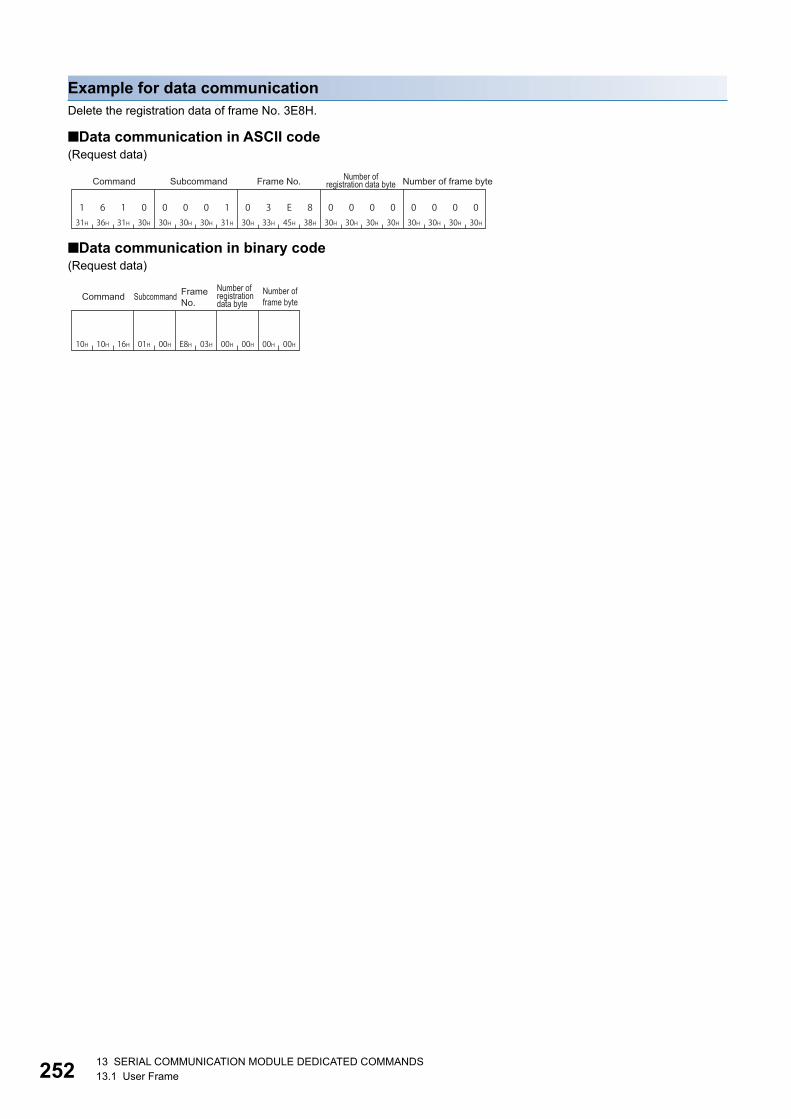
25213 SERIAL COMMUNICATION MODULE DEDICATED COMMANDS13.1 User Frame
Example for data communicationDelete the registration data of frame No. 3E8H.
■Data communication in ASCII code(Request data)
■Data communication in binary code(Request data)
1 6 1 031H 36H 31H 30H 30H 30H 30H 31H
0 0 0 130H 33H 45H 38H
0 3 E 830H 30H 30H 30H
0 0 0 030H 30H 30H 30H
0 0 0 0
Command Subcommand Frame No. Number of frame byteNumber of registration data byte
10H 10H 16H 01H 00H E8H 03H 00H 00H 00H 00H
Subcommand Frame No.Command Number of
frame byteNumber of registration data byte
13 SERIAL COMMUNICATION MODULE DEDICATED COMMANDS13.2 Global Function 253
13
13.2 Global FunctionThe global function is a function to turn ON/OFF the global signals (input signals: X1A/X1B) of serial communication module
connected to external devices with the multidrop communications.
This is used as interlock signals for emergency command, simultaneous startup, and applicability of data transmission/
reception to CPU modules.
The command can only be used for C24 (including multidrop connection station) connected to the external
device. It cannot be used via network.
The global signal is turned OFF by powering OFF, resetting, or switching the mode of CPU module.
Compatibility with global function of Computer link moduleThis function (command: 1618) is compatible with GW command for dedicated protocol of Computer link module.
■Operation of serial communication module when GW command is receivedWhen GW command is executed from Computer link module connected with the multidrop connection, the global signal (input
signal: X1A/X1B) at the side where the command was received turns ON/OFF.
• Received from CH1: X1A
• Received from CH2: X1B
■Command: Operation of computer link module when 1618 is receivedWhen this function (command: 1618) is used to Computer link module, the global signal (input signal: X2) of Computer link
module turns ON/OFF.

25413 SERIAL COMMUNICATION MODULE DEDICATED COMMANDS13.2 Global Function
Global signal ON/OFF (command: 1618)Turn ON/OFF the global signal from an external device.
Message formatThe following shows the message format of the request data and response data of the command.
■Request data
■Response dataThere is no response data for this command.
Data specified by request data
■Command
■Subcommand
■Global signal specificationSpecify which global signal (X1A or X1B) is turned ON/OFF.
The target station (all stations/only 1 specified station) of which global signal is turned ON/OFF is specified by
a station No.
Page 50 Station No.
ASCII code Binary code
Item ASCII code Binary code
OFF
ON
Global signal to be turned ON/OFF ASCII code Binary code
Global signal at the side where command was
received
• Received from CH1: X1A
• Received from CH2: X1B
X1A regardless of the interface
X1B regardless of the interface
Global signal specificationSubcommandCommand
131H
636H
131H
838H 18H 16H
030H
030H
030H
030H 00H 00H
030H
030H
030H
131H 01H 00H
030H
030H
030H
030H 00H 00H
030H
030H
030H
131H 01H 00H
030H
030H
030H
232H 02H 00H

13 SERIAL COMMUNICATION MODULE DEDICATED COMMANDS13.2 Global Function 255
13
Communication example (turn ON)Turn the global signal X1A ON.
■Data communications in ASCII code (Format 1)(Request data)
■Data communications in binary code (Format 5)(Request data)
Communication example (turn OFF)Turn OFF the global signal X1A.
■Data communications in ASCII code (Format 1)(Request data)
■Data communications in binary code (Format 5)(Request data)
31H 36H 38H
131H
16 830H 30H 30H 30H31H 31H30H 30H
10 0 0 0 0 0 1
Command Subcommand Global signal specification
16H 01H18H 00H 01H 00H
SubcommandGlobal signal specificationCommand
31H 36H 38H
131H
16 830H 30H 30H 30H 31H30H 30H
0 0 0 0 0 0 1030H
Command Subcommand Global signal specification
16H18H 01H 00H00H 00H
SubcommandGlobal signal specificationCommand

25613 SERIAL COMMUNICATION MODULE DEDICATED COMMANDS13.3 Transmission sequence initialization function
13.3 Transmission sequence initialization functionThe transmission sequence initialization function is a function to initialize the transmission sequence of data communication
using format 5 of 4C frame, and to place C24 into the state where it waits to receive commands from external devices.
The command can only be used for C24 (including multidrop connection station) connected to the external
device. It cannot be used via network.
Initialize transmission sequence (command: 1615)Initialize the transmission sequence of data communication using format 5 of 4C frame, and make C24 wait to receive
commands from external devices.
This function is equivalent to EOT, CL during data communication in ASCII code. Use the control codes, EOT,
CL during data communication in ASCII code. (Page 34 EOT(04H), CL(0CH))
Message formatThe following shows the message format of the request data and response data of the command.
■Request data
■Response dataThere is no response data for this command.
Data specified by request data
■Command
■Subcommand
Example for data communicationInitialize transmission sequence.
(Request data)
Binary code
Binary code
Command Subcommand
15H 16H
00H 00H
15H 16H 00H 00H
Subcommand

13 SERIAL COMMUNICATION MODULE DEDICATED COMMANDS13.4 Mode Switching Function 257
13
13.4 Mode Switching FunctionThe mode switching function is a function to switch the current communication protocol (operation mode) or transmission
specification for the specified interface from external devices after C24 starts up. For more details on the mode switching
function, refer to the following manuals.
MELSEC-Q/L Serial Communication Module User's Manual (Application)
MELSEC iQ-R Serial Communication Module User's Manual(Application)
The command can only be used for C24 (including multidrop connection station) connected to the external
device. It cannot be used via network.
Data to be specified in commandThis section explains the contents and specification method for data item which is set in the command to switch mode.
Channel No.Specify the target interface.
Switching instructionSelect which specify the contents to be switched, by data in the command or by Engineering tool.
■Data communication in ASCII codeConvert the numerical value to 2-digit ASCII code (hexadecimal), and send it from the upper digits.
■Data communication in binary codeSend a 1-byte numerical value from lower byte (L: bits 0 to 7).
Ex.
When the switching instruction is '1' (Only mode No. is specified by command)
Target interface ASCII code Binary code
CH1
CH2
Bit Item Setting of Engineering tool OFF (0) ON (1)
b0 Mode No. Communication protocol setting Specified by Engineering tool Specified by command
b1 Transmission
setting
Transmission setting
b2 Communicati
on speed
Communication speed setting
b3 to b7 (Fixed to '0')
ASCII code Binary code
030H
131H 01H
030H
232H 02H
030H
131H 01H

25813 SERIAL COMMUNICATION MODULE DEDICATED COMMANDS13.4 Mode Switching Function
Mode No.Specify the communication protocol setting after switching the C24 mode.
■Data communication in ASCII codeConvert the numerical value to 2-digit ASCII code (hexadecimal), and send it from the upper digits.
■Data communication in binary codeSend a 1-byte numerical value from lower byte (L: bits 0 to 7).
Ex.
When mode No. is '1' (MC protocol (Format 1))
Mode No. Operation mode
01H MC Protocol (Format 1)
02H MC Protocol (Format 2)
03H MC Protocol (Format 3)
04H MC Protocol (Format 4)
05H MC Protocol (Format 5)
06H Nonprocedural protocol
07H Bidirectional protocol
09H Predefined protocol
FFH MELSOFT connection, GX Developer connection
ASCII code Binary code
030H
131H 01H

13 SERIAL COMMUNICATION MODULE DEDICATED COMMANDS13.4 Mode Switching Function 259
13
Transmission settingSpecify the transmission setting after switching the C24 mode.
For the transmission setting, refer to the following manuals.
MELSEC iQ-R Serial Communication Module User's Manual(Application)
MELSEC-Q/L Serial Communication Module User's Manual (Application)
■Data communication in ASCII codeConvert the numerical value to 4-digit ASCII code (hexadecimal), and send it from the upper digits.
■Data communication in binary codeSend a 1-byte numerical value from lower byte (L: bits 0 to 7).
When the transmission settings are as follows:
Bit Item OFF (0) ON (1)
b0 Operation setting Independent Interlink
b1 Data bit 7 8
b2 Parity bit None Yes
b3 Odd/even parity Odd Even
b4 Stop bit 1 2
b5 Sum check code None Yes
b6 Online change Disable Enable
b7 Setting change Disable Enable
Bit Item Setting ON/OFF
b0 Operation setting Independent OFF
b1 Data bit 8 ON
b2 Parity bit Yes ON
b3 Odd/even parity Odd OFF
b4 Stop bit 1 OFF
b5 Sum check code Yes ON
b6 Online change Enable ON
b7 Setting change Enable ON
ASCII code Binary code
E45H
636H E6H

26013 SERIAL COMMUNICATION MODULE DEDICATED COMMANDS13.4 Mode Switching Function
Communication speedSpecify the communication speed after switching the C24 mode.
The communication speed that can be set differs depending on the module or channel.
For the communication speed setting, refer to the following manuals.
MELSEC iQ-R Serial Communication Module User's Manual(Application)
MELSEC-Q/L Serial Communication Module User's Manual (Application)
■Data communication in ASCII codeConvert the numerical value to 4-digit ASCII code (hexadecimal), and send it from the upper digits.
■Data communication in binary codeSend a 1-byte numerical value from lower byte (L: bits 0 to 7).
Ex.
For communication speed 05H (9600 bps)
Specified value Communication speed
0FH 50bps
00H 300bps
01H 600bps
02H 1200bps
03H 2400bps
04H 4800bps
05H 9600bps
06H 14400bps
07H 19200bps
08H 28800bps
09H 38400bps
0AH 57600bps
0BH 115200bps
0CH 230400bps
ASCII code Binary code
030H
535H 05H

13 SERIAL COMMUNICATION MODULE DEDICATED COMMANDS13.4 Mode Switching Function 261
13
Switch mode (command: 1612)Switch the C24 mode from external devices.
Message formatThe following shows the message format of the request data and response data of the command.
■Request data
■Response dataThere is no response data for this command.
Data specified by request data
■Command
■Subcommand
■Channel No.Specify the target interface (CH1/CH2). (Page 257 Channel No.)
■Switching instructionSelect which specify the contents to be switched, by data in the command or by Engineering tool. (Page 257 Switching
instruction)
: Specified by command, : Specified by Engineering tool
■Mode No.Specify the operation mode within the range of 1H to 9H or FFH. (Page 258 Mode No.)
When the setting by command enabled (Switching instruction: 1, 3, 5, or 7), the operation mode is changed according to the
specified value.
As for the setting by command is disabled (Switching instruction: 0, 2, 4, or 6), the operation mode is changed according to
the Communication protocol setting set with Engineering tool
Even when the setting by command is disabled, specify the value (1 to 9H or FFH). (Do not specify '0'.)
ASCII code Binary code
ASCII code Binary code
Switching instruction Mode No. Transmission setting Communication speed
0
1
2
3
4
5
6
7
Command Subcommand Channel No. Switching instruction Mode No.
Transmission setting
Communication speed
131H
636H
131H
232H 12H 16H
030H
030H
030H
030H 00H 00H

26213 SERIAL COMMUNICATION MODULE DEDICATED COMMANDS13.4 Mode Switching Function
■Transmission settingSpecify the transmission setting. (Page 259 Transmission setting)
When the setting by command is enabled (Switching instruction: 2, 3, 6, or 7), the transmission setting is changed according
to the specified value.
As for the setting by command is disabled (Switching instruction: 0, 1, 4, or 5), the transmission setting is changed according
to the transmission setting set with Engineering tool
When the setting is invalid, specify '0'.
■Communication speedSpecify the communication speed. (Page 260 Communication speed)
When the setting by command is enabled (Switching instruction: 4, 5, 6, or 7), the communication speed is changed according
to the specified value.
When the setting by command is disabled (Switching instruction: 0, 1, 2, or 3), the communication speed is changed
according to the communication speed setting set with Engineering tool.
When the setting is invalid, specify '0'.
ASCII code Binary code
ASCII code Binary code
030H
030H 00H
030H
030H 00H

13 SERIAL COMMUNICATION MODULE DEDICATED COMMANDS13.4 Mode Switching Function 263
13
Example for data communicationPerform mode switching for CH1 interface.
• Operation mode: MC protocol (Format 1) (Specified value: 01H)
• Operation setting: Following settings (Specified value: B0H)
• Communication speed: 9600bps (Specified value: 05H)
■Data communication in ASCII code(Request data)
■Data communication in binary code(Request data)
Item Setting Bit ON/OFF
Operation setting Independent b0 OFF
Data bit 7 b1 OFF
Parity bit None b2 OFF
Odd/even parity Odd b3 OFF
Stop bit 2 b4 ON
Sum check code Yes b5 ON
Online change Disable b6 OFF
Setting change Enable b7 ON
31H 36H 32H
131H
16 230H 30H 30H 30H30H 31H 30H
0 0 0 0 01037H 30H 30H 42H 30H 30H 35H
7 0 1 0B 0 5
Channel No.
Switching instruction
Mode No.
Command Subcommand Transmission setting
Communication speed
12H 16H 07H 05HB0H00H 01H 01H00H
Channel No.
Switching instruction
Mode No.
Transmission setting
Communication speed
Command Subcommand

26413 SERIAL COMMUNICATION MODULE DEDICATED COMMANDS13.5 Programmable controller CPU monitoring function
13.5 Programmable controller CPU monitoring functionProgrammable controller CPU monitoring function is a function that C24 monitors CPU module with the monitoring
information which was registered in advance.
For the Programmable controller CPU monitoring function, refer to the following manuals.
• MELSEC iQ-R Serial Communication Module User's Manual(Application)
• MELSEC-Q/L Serial Communication Module User's Manual (Application)
The command can only be used for C24 (including multidrop connection station) connected to the external
device. It cannot be used via network.
Data to be specified in command
Cycle time unitsSpecify the unit of cycle time.
Cycle timeSpecify the time interval (period for 1 cycle) that C24 reads the monitoring information from CPU module.
■Data communication in ASCII codeConvert the numerical value to 4-digit ASCII code (hexadecimal), and send it from the upper digits.
■Data communication in binary codeSend 2-byte numerical values from lower byte (L: bits 0 to 7).
Programmable controller CPU monitoring functionSpecify the send timing (fixed cycle send/condition match send) of the monitoring result.
Time unit ASCII code Binary code
100 ms
1 second
1 minute
Programmable controller CPU monitoring function
ASCII code Binary code
Fixed cycle send
(Sending information in the cycle time interval.)
Condition match send
(Sending information when the specified
condition matches.)
030H
030H 00H
030H
131H 01H
030H
232H 02H
030H
131H 01H
030H
232H 02H
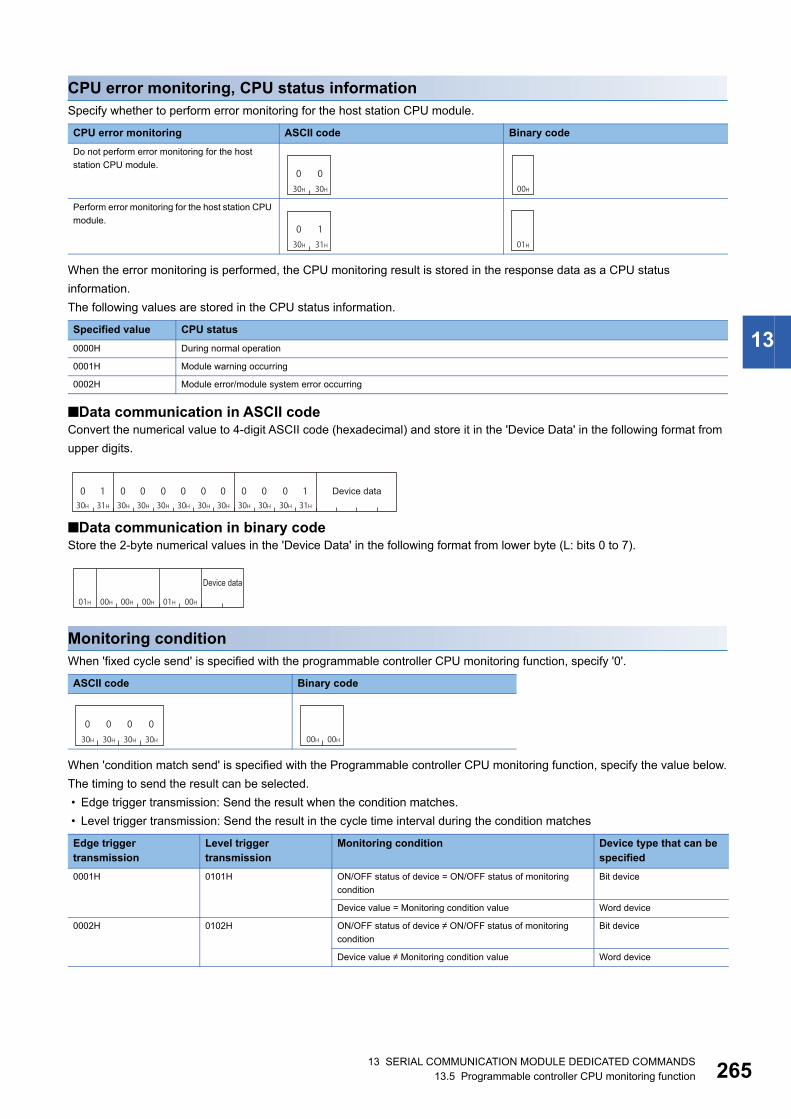
13 SERIAL COMMUNICATION MODULE DEDICATED COMMANDS13.5 Programmable controller CPU monitoring function 265
13
CPU error monitoring, CPU status informationSpecify whether to perform error monitoring for the host station CPU module.
When the error monitoring is performed, the CPU monitoring result is stored in the response data as a CPU status
information.
The following values are stored in the CPU status information.
■Data communication in ASCII codeConvert the numerical value to 4-digit ASCII code (hexadecimal) and store it in the 'Device Data' in the following format from
upper digits.
■Data communication in binary codeStore the 2-byte numerical values in the 'Device Data' in the following format from lower byte (L: bits 0 to 7).
Monitoring conditionWhen 'fixed cycle send' is specified with the programmable controller CPU monitoring function, specify '0'.
When 'condition match send' is specified with the Programmable controller CPU monitoring function, specify the value below.
The timing to send the result can be selected.
• Edge trigger transmission: Send the result when the condition matches.
• Level trigger transmission: Send the result in the cycle time interval during the condition matches
CPU error monitoring ASCII code Binary code
Do not perform error monitoring for the host
station CPU module.
Perform error monitoring for the host station CPU
module.
Specified value CPU status
0000H During normal operation
0001H Module warning occurring
0002H Module error/module system error occurring
ASCII code Binary code
Edge trigger transmission
Level trigger transmission
Monitoring condition Device type that can be specified
0001H 0101H ON/OFF status of device = ON/OFF status of monitoring
condition
Bit device
Device value = Monitoring condition value Word device
0002H 0102H ON/OFF status of device ON/OFF status of monitoring
condition
Bit device
Device value Monitoring condition value Word device
030H
030H 00H
030H
131H 01H
0 1 030H 31H 30H
030H
0 0 030H 30H 30H
030H
030H
030H
030H
131H
Device data
01H 00H 00H 00H 01H 00H
Device data
030H
030H
030H
030H 00H 00H

26613 SERIAL COMMUNICATION MODULE DEDICATED COMMANDS13.5 Programmable controller CPU monitoring function
■Data communication in ASCII codeConvert the numerical value to 4-digit ASCII code (hexadecimal), and send it from the upper digits.
■Data communication in binary codeSend 2-byte numerical values from lower byte (L: bits 0 to 7).
Monitoring condition valueWhen 'fixed cycle send' is specified with the Programmable controller CPU monitoring function, specify '0'.
When 'condition match send' is specified with the Programmable controller CPU monitoring function, specify the value below.
■Data communication in ASCII codeConvert the numerical value to 4-digit ASCII code (hexadecimal), and send it from the upper digits.
■Data communication in binary codeSend 2-byte numerical values from lower byte (L: bits 0 to 7).
0003H 0103H Device value Monitoring condition value Unsigned Word device
0004H 0104H Device value < Monitoring condition value
0005H 0105H Device value Monitoring condition value
0006H 0106H Device value > Monitoring condition value
0007H 0107H Device value Monitoring condition value Signed
0008H 0108H Device value < Monitoring condition value
0009H 0109H Device value Monitoring condition value
000AH 010AH Device value > Monitoring condition value
ASCII code Binary code
Monitoring condition value Monitoring condition value Device type
0000H OFF Bit device
0001H ON
0000H to FFFFH Numerical value Word device
Edge trigger transmission
Level trigger transmission
Monitoring condition Device type that can be specified
030H
030H
030H
030H 00H 00H
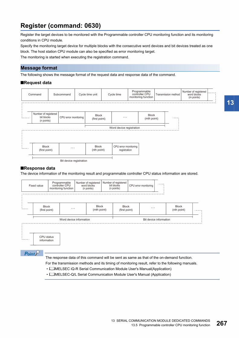
13 SERIAL COMMUNICATION MODULE DEDICATED COMMANDS13.5 Programmable controller CPU monitoring function 267
13
Register (command: 0630)Register the target devices to be monitored with the Programmable controller CPU monitoring function and its monitoring
conditions in CPU module.
Specify the monitoring target device for multiple blocks with the consecutive word devices and bit devices treated as one
block. The host station CPU module can also be specified as error monitoring target.
The monitoring is started when executing the registration command.
Message formatThe following shows the message format of the request data and response data of the command.
■Request data
■Response dataThe device information of the monitoring result and programmable controller CPU status information are stored.
The response data of this command will be sent as same as that of the on-demand function.
For the transmission methods and its timing of monitoring result, refer to the following manuals.
• MELSEC iQ-R Serial Communication Module User's Manual(Application)
• MELSEC-Q/L Serial Communication Module User's Manual (Application)
Number of registered word blocks (m points)
Programmable controller CPU
monitoring functionCommand Subcommand Cycle time unit Cycle time Transmission method
Number of registered bit blocks (n points)
Block (mth point)
Block (first point)CPU error monitoring
Word device registration
Block (nth point)
Block (first point)
CPU error monitoring registration
Bit device registration
Number of registered word blocks (n points)
Number of registered bit blocks (n points)
Programmable controller CPU
monitoring functionFixed value CPU error monitoring
Block (mth point)
Block (nth point)
Block (first point)
Block (first point)
Word device information Bit device information
CPU status information

26813 SERIAL COMMUNICATION MODULE DEDICATED COMMANDS13.5 Programmable controller CPU monitoring function
Data specified by request data
■Command
■Subcommand
■Cycle time units, cycle timeSpecify the following time interval (period for 1 cycle). (Page 264 Cycle time)
• Time interval that C24 reads monitoring information from CPU module
• Transmission interval of monitoring result when 'fixed cycle send' is specified with the Programmable controller CPU
monitoring function
The time unit (100 ms/1 second/1 minute) can be selected. (Page 264 Cycle time units)
■Programmable controller CPU monitoring functionSpecify the send timing (fixed cycle send/condition match send) of the monitoring result. (Page 264 Programmable
controller CPU monitoring function)
■Transmission methodFixed '0'.
■Number of registered word blocks, number of registered bit blocksSpecify the number of blocks of word device registration and bit device registration. (Page 71 Number of blocks)
■CPU error monitoring, CPU error monitoring registrationSpecify whether to perform error monitoring (status monitoring) of host station CPU module together. (Page 265 CPU
error monitoring, CPU status information)
• When do not perform CPU error monitoring (0): CPU error monitoring registration is not required.
• When perform CPU error monitoring (1): Register the following fixed values to CPU error monitoring registration.
ASCII code Binary code
ASCII code Binary code
ASCII code Binary code
ASCII code Binary code
030H
636H
333H
030H 30H 06H
030H
030H
030H
030H 00H 00H
030H
030H 00H
0 1 030H 31H 30H
030H
0 0 030H 30H 30H
0 0 030H 30H 30H
131H
030H
030H
030H
030H
131H
535H
030H
030H
030H 00H 00H 00H 01H 01H 00H 05H 00H 01H 00H

13 SERIAL COMMUNICATION MODULE DEDICATED COMMANDS13.5 Programmable controller CPU monitoring function 269
13
■Word device registration, bit device registrationSpecify the monitoring target device for multiple blocks with the consecutive word devices and bit devices treated as one
block.
Specify the following items for every block.
• Monitoring start device: Specify the device code and device number. (Page 65 Devices)
• Number of registered points: Specify the device points from the start device in word units. (Page 70 Number of device
points)
• Monitoring condition: Specify the monitoring condition and transmission method for the device to be registered. (Page
265 Monitoring condition)
• Monitoring condition value: Specify a value to judge the conditions have been matched or ON/OFF state of the bit.
(Page 266 Monitoring condition value)
Monitoring start device
Number of registered points
Monitoring condition
Monitoring condition value
Block (1 point)

27013 SERIAL COMMUNICATION MODULE DEDICATED COMMANDS13.5 Programmable controller CPU monitoring function
Data to be stored by response data
■Fixed value
■Programmable controller CPU monitoring functionThe send timing (fixed cycle send/condition match send) of the monitoring result is stored. (Page 264 Programmable
controller CPU monitoring function)
■Number of registered word blocks, number of registered bit blocksThe number of blocks of word device information and bit device information are stored. (Page 71 Number of blocks)
■Word device information, bit device informationThe information of device, whose monitoring condition is satisfied, is stored for multiple blocks with the consecutive word
devices and bit devices treated as one block.
The following items are stored for each block.
• Monitoring start device: Device code and device number are stored. (Page 65 Devices)
• Number of registered points: Number of device data points is stored in word unit. (Page 70 Number of device points)
• Device data: The device value is stored.
The order of device data differ depending on the setting of "Word/byte units designation" in Engineering tool.
For byte units, handle the word data as 2-byte data and send the numerical values from the lower byte (L: bits 0 to 7).
Ex.
2 points data of word device (1234H, 5678H)
• Word unit (0)
• Byte unit (1)
■CPU error monitoring, CPU status informationSpecify whether to include the result of error monitoring (state monitoring) of the host station CPU module. (Page 265
CPU error monitoring, CPU status information)
• When do not perform CPU error monitoring (0): CPU status information is not stored.
• When perform CPU error monitoring (1): CPU status information is stored.
ASCII code Binary code
ASCII code Binary code
ASCII code Binary code
232H
131H
030H
232H 02H 21H
Monitoring start device
Number of registered points
Device data
Block (1 point)
1 2 331H 32H 33H
434H
5 6 735H 36H 37H
8 38H 12H 34H 56H 78H
3 4 133H 34H 31H
232H
7 8 537H 38H 35H
6 36H 34H 12H 78H 56H

13 SERIAL COMMUNICATION MODULE DEDICATED COMMANDS13.5 Programmable controller CPU monitoring function 271
13
Communication example (for fixed cycle send)Perform the Programmable controller CPU monitoring registration with the following conditions.
• Cycle time units, cycle time: 30 seconds
• Programmable controller CPU monitoring function: Fixed cycle send
• Number of registered word blocks: 2 blocks
• Number of registered bit blocks: 1 block
• CPU error monitoring: Included
The response data indicates the following data.
(1) Word device information (1-point)
*1 The additional code is added. (Page 35 Additional code (10H))
(2) Bit device information (1-point)
(3) CPU status information
• CPU status information: Module warning occurring (0001)
Block Monitoring start device Registered points
Word device registration (1-point) D0 4 points
Word device registration (2-point) W100 8 points
Bit device registration (1-point) M0 2 points
Device data D0 D1 D2 D3
Device value Decimal 99 4144 5445 10240
Hexadecimal 0063H 1030H 1545H 2800H
ASCII code Word unit 30303633 31303330 31353435 32383030
Byte unit 36333030 33303130 34353135 30303238
Binary code Word unit 0063 101030*1 1545 2800
Byte unit 6300 301010*1 4515 0028
Device data M15 to M8 M7 to M0 M31 to M24 M23 to M16
Device value Bit 0 0 0 1 0 0 0 1 0 0 1 1 0 0 0 1 0 1 0 0 1 0 0 0 0 1 0 0 1 0 0 1
Byte 11H 31H 48H 49H
Word 1131H 4849H
ASCII code Word unit 31313331 34383439
Byte unit 33313131 34393438
Binary code Word unit 1131 4849
Byte unit 3111 4948

27213 SERIAL COMMUNICATION MODULE DEDICATED COMMANDS13.5 Programmable controller CPU monitoring function
■Data communication in ASCII code(Request data)
(Response data)
In the figure (1) and (2), set the value of "ASCII Code" in the table of "Device data" of each response data.
The order of device data differ depending on the setting of "Word/byte units designation" in Engineering tool.
0 130H 31H
0 0 130H 30H 31H
E 0 145H 30H 31H
0 0 030H 30H 30H
232H
0 1 030H 31H 30H
131H
0 6 330H 36H 33H
030H
0 0 030H 30H 30H
030H
D * 044H 2AH 30H
030H
0 0 030H 30H 30H
030H
0 0 030H 30H 30H
434H
0 0 030H 30H 30H
030H
0 0 030H 30H 30H
030H
W * 057H 2AH 30H
030H
0 1 030H 31H 30H
030H
0 0 030H 30H 30H
838H
0 0 030H 30H 30H
030H
0 0 030H 30H 30H
030H
M * 04DH 2AH 30H
030H
0 0 030H 30H 30H
030H
0 0 030H 30H 30H
232H
0 0 030H 30H 30H
030H
0 0 030H 30H 30H
030H
0 1 030H 31H 30H
030H
0 0 030H 30H 30H
0 0 030H 30H 30H
131H
030H
030H
030H
030H
131H
535H
030H
030H
030H
SubcommandCycle
time unitTransmission
method
Number of registered
word blocksCPU error monitoring
Number of registered bit blocks
Cycle time
Monitoring start deviceNumber of registered
pointsMonitoring condition
Monitoring condition value
Monitoring start deviceNumber of
registered pointsMonitoring condition
Monitoring condition value
Monitoring start deviceNumber of
registered pointsMonitoring condition
Monitoring condition value
Word device registration (first point)
Word device registration (second point)
Bit device registration (first point)
D0 to D3
W100 to D107
M0 to M31
CPU error monitoring registration (Fixed value)
Programmable controller CPU
monitoring function
D * 044H 2AH 30H
030H
0 0 030H 30H 30H
030H
0 0 030H 30H 30H
434H
M * 04DH 2AH 30H
030H
0 0 030H 30H 30H
030H
0 0 030H 30H 30H
232H
0 1 030H 31H 30H
030H
0 0 030H 30H 30H
030H
030H
030H
030H
131H
131H
030H
030H
030H
0 1 030H 31H 30H
232H
0 1 030H 31H 30H
131H
2 1 032H 31H 30H
232H
(1)
(2)
Programmable controller CPU
monitoring function
Number of registered
word blocks
Number of registered bit blocks
CPU error monitoring
Fixed value
Word device information
Monitoring start deviceNumber of
registered points Device data
(first point) (second point)
Bit device information Number of registered points Device dataMonitoring start device
CPU status informationDevice data
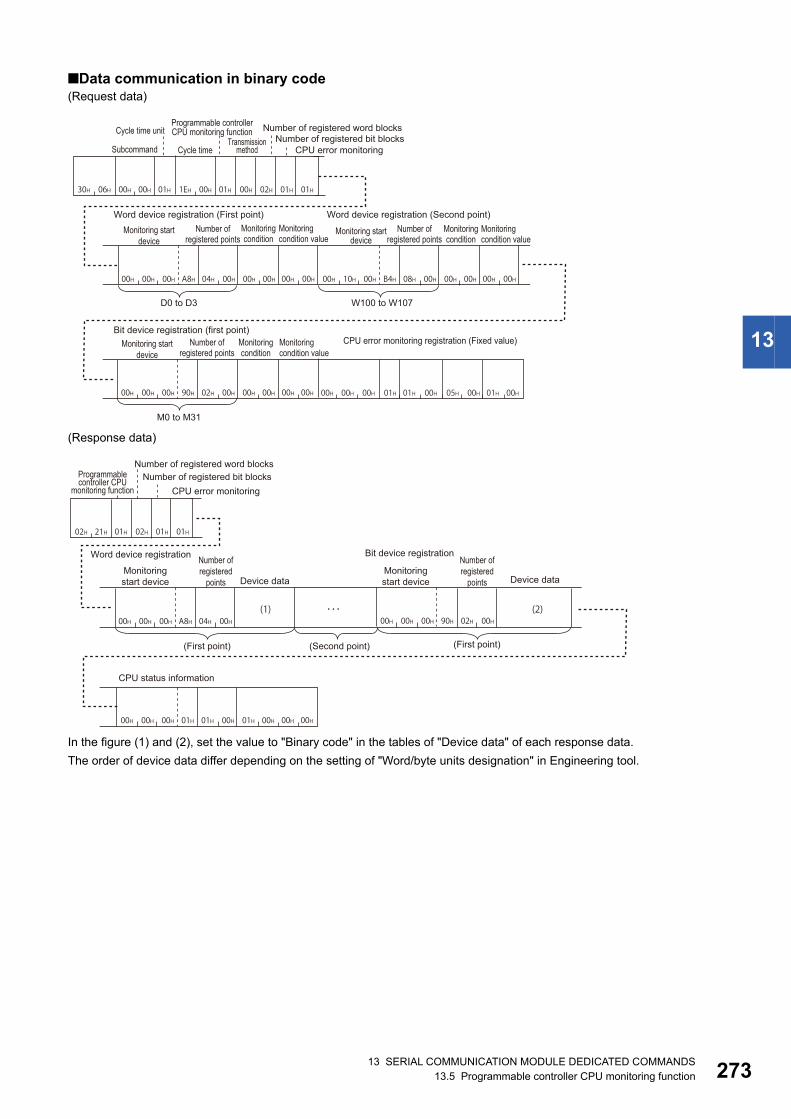
13 SERIAL COMMUNICATION MODULE DEDICATED COMMANDS13.5 Programmable controller CPU monitoring function 273
13
■Data communication in binary code(Request data)
(Response data)
In the figure (1) and (2), set the value to "Binary code" in the tables of "Device data" of each response data.
The order of device data differ depending on the setting of "Word/byte units designation" in Engineering tool.
00H 02H 01H 01H30H 06H 00H 00H 01H 1EH 00H 01H
00H 00H 00H A8H 04H 00H 00H 00H 00H 00H 00H 10H 00H B4H 08H 00H 00H 00H 00H 00H
00H 00H 00H 90H 02H 00H 00H 00H 00H 00H 00H 00H 00H 01H 01H 00H 05H 00H 01H 00H
Cycle time unitProgrammable controller CPU monitoring function Number of registered word blocks
SubcommandTransmission
methodNumber of registered bit blocks
Cycle time CPU error monitoring
Word device registration (First point) Word device registration (Second point)Number of
registered pointsMonitoring condition value
Number of registered points
Monitoring condition
Monitoring condition value
Monitoring start device
Monitoring start device
D0 to D3 W100 to W107
Bit device registration (first point)Number of
registered pointsMonitoring condition value
CPU error monitoring registration (Fixed value)Monitoring start device
M0 to M31
Monitoring condition
Monitoring condition
(1) (2)
02H 01H 01H21H02H 01H
00H 00H 00H A8H 04H 00H 00H 00H 00H 90H 02H 00H
00H 00H 00H 01H 01H 00H 01H 00H 00H 00H
Number of registered word blocksProgrammable controller CPU
monitoring functionNumber of registered bit blocks
CPU error monitoring
Word device registration Bit device registrationNumber of registered
points
Number of registered
pointsMonitoring start device Device dataDevice data
(First point)(First point) (Second point)
CPU status information
Monitoring start device

27413 SERIAL COMMUNICATION MODULE DEDICATED COMMANDS13.5 Programmable controller CPU monitoring function
Communication example (for condition match send)Perform the Programmable controller CPU monitoring registration function with the following conditions.
• Cycle time units, cycle time: 30 seconds
• Programmable controller CPU monitoring function: Condition match send
• Number of registered word blocks: 2 blocks
• Number of registered bit blocks: 1 block
• CPU error monitoring designation: Included
The response data indicates the following data.
For the condition match send, the registration data information will be sent individually. (Device information will be sent per
block.)
(1) When the condition of D0 = 99 (word device registration (first point) of request data) is satisfied.
*1 The additional code is added. (Page 35 Additional code (10H))
(2) When the condition of M0 OFF (bit device registration (1 point) of request data) is satisfied.
(3) When CPU error monitoring condition is satisfied
• CPU status information: Module warning occurring (0001)
When the error is detected at the first time, the monitoring result is sent with the equivalent method to the edge trigger
transmission.
Block Monitoring start device
Number of registered points
Monitoring condition Monitoring condition value
Word device registration (1-
point)
D0 4 points Edge triggered transmission: Device value = Monitoring condition value 99
Word device registration (2-
point)
W100 8 points Edge triggered transmission: Device value Monitoring condition value 0
Bit device registration (1-
point)
M0 2 points Edge trigger transmission: ON/OFF status of device ON/OFF status of
monitoring condition
OFF
Device data D0 D1 D2 D3
Device value Decimal 99 4144 5445 10240
Hexadecimal 0063H 1030H 1545H 2800H
ASCII code Word unit 30303633 31303330 31353435 32383030
Byte unit 36333030 33303130 34353135 30303238
Binary code Word unit 0063 101030*1 1545 2800
Byte unit 6300 301010*1 4515 0028
Device data M15 to M8 M7 to M0 M31 to M24 M23 to M16
Device value Bit 0 0 0 1 0 0 0 1 0 0 1 1 0 0 0 1 0 1 0 0 1 0 0 0 0 1 0 0 1 0 0 1
Byte 11H 31H 48H 49H
Word 1131H 4849H
ASCII code Word unit 31313331 34383439
Byte unit 33313131 34393438
Binary code Word unit 1131 4849
Byte unit 3111 4948

13 SERIAL COMMUNICATION MODULE DEDICATED COMMANDS13.5 Programmable controller CPU monitoring function 275
13
■Data communication in ASCII code(Request data)
(Response data)
In the figure (1) and (2), set the value of "ASCII Code" in the table of "Device data" of each response data.
The order of device data differ depending on the setting of "Word/byte units designation" in Engineering tool.
0 130H 31H
0 0 130H 30H 31H
E 0 245H 30H 32H
0 0 030H 30H 30H
232H
0 1 030H 31H 30H
131H
0 6 330H 36H 33H
030H
0 0 030H 30H 30H
030H
D * 044H 2AH 30H
030H
0 0 030H 30H 30H
030H
0 0 030H 30H 30H
434H
0 0 030H 30H 30H
131H
0 0 630H 30H 36H
333H
W * 057H 2AH 30H
030H
0 1 030H 31H 30H
030H
0 0 030H 30H 30H
838H
0 0 030H 30H 30H
232H
0 0 030H 30H 30H
030H
M * 04DH 2AH 30H
030H
0 0 030H 30H 30H
030H
0 0 030H 30H 30H
232H
0 0 030H 30H 30H
232H
0 0 030H 30H 30H
030H
0 1 030H 31H 30H
030H
0 0 030H 30H 30H
0 0 030H 30H 30H
131H
030H
030H
030H
030H
131H
535H
030H
030H
030H
SubcommandCycle
time unitTransmission
methodNumber
of registered word blocks
CPU error monitoring
Number of registered
bit blocksCycle time
Monitoring start deviceNumber of
registered pointsMonitoring condition
Monitoring condition value
Monitoring start deviceNumber of
registered pointsMonitoring condition
Monitoring condition value
Monitoring start deviceNumber of
registered pointsMonitoring condition
Monitoring condition value
Word device registration (first point)
Word device registration (second point)
Bit device registration (first point)
D0 to D3 D0=99
W100 to D107 W100≠0
M0 to M31 M0≠OFF
CPU error monitoring registration (Fixed value)
Programmable controller CPU
monitoring function
0 2 030H 32H 30H
131H
0 0 030H 30H 30H
030H
2 1 032H 31H 30H
232H
D * 044H 2AH 30H
030H
0 0 030H 30H 30H
030H
0 0 030H 30H 30H
434H
232H
0 2 030H 32H 30H
030H
0 1 030H 31H 30H
030H
2 1 032H 31H 30H
232H
M * 04DH 2AH 30H
030H
0 0 030H 30H 30H
030H
0 0 030H 30H 30H
(2)
(1)
132H
0 2 030H 32H 30H
030H
0 0 030H 30H 30H
131H
2 1 032H 31H 30H
232H
0 1 030H 31H 30H
030H
0 0 030H 30H 30H
030H
0 0 030H 30H 30H
132H
0 0 030H 30H 30H
When the condition (D0 = 99) of word device registration (first point) is establishedNumber
of registered word blocks
Number of registered
bit blocksCPU error monitoring
Programmable controller CPU
monitoring function
Number of registered word blocks
Number of registered
bit blocksCPU error monitoring
Programmable controller CPU
monitoring function
Number of registered word blocks
Number of registered
bit blocksCPU error monitoring
Programmable controller CPU
monitoring function
Fixed value Monitoring start deviceNumber of
registered points
Number of registered points
Device data
Word device informationWhen the condition (M0 ≠ OFF) of bit device registration (first point) is established
Fixed value Monitoring start device Device data
Bit device information
When the condition of CPU error monitoring is established(Module warning being generated)
Fixed value Fixed value Device data
CPU status information

27613 SERIAL COMMUNICATION MODULE DEDICATED COMMANDS13.5 Programmable controller CPU monitoring function
■Data communication in binary code(Request data)
(Response data)
In the figure (1) and (2), set the value of "Binary code" in the tables of "Device data" of each response data.
The order of device data differ depending on the setting of "Word/byte units designation" in Engineering tool.
00H 00H 00H 01H 01H 00H 05H 00H 01H 00H
00H 02H 01H 01H30H 06H 00H 00H 01H 1EH 00H 02H
00H 00H 00H A8H 04H 00H 01H 00H 63H 00H 00H 10H 00H B4H 08H 00H 02H 00H 00H 00H
00H 00H 00H 90H 02H 00H 02H 00H 00H 00H
Programmable controller CPU monitoring function
Cycle time unit Number of registered word blocksTransmission
methodNumber of registered bit blocks
Subcommand Cycle time CPU error monitoring
Word device registration (first point) Word device registration (second point)Number of
registered pointsMonitoring condition
Monitoring condition value
Monitoring start device
D0 to D3 D0=99 W100 to D107 W100≠0
Bit device registration (first point)Number of
registered pointsMonitoring condition
Monitoring condition value CPU error monitoring registration (Fixed value)
Monitoring start device
M0 to M31 M0≠OFF
Monitoring condition
Monitoring condition value
Number of registered points
Monitoring start device
(1)01H 00H 00H21H02H 02H 00H 00H 00H A8H 04H 00H
(2)00H 01H 00H21H02H 02H 00H 00H 00H 90H 02H 00H
00H 01H 01H 00H 01H 00H 00H 00H00H 00H 01H21H02H 02H 00H 00H
When the condition (D0 = 99) of word device registration (first point) is establishedNumber of registered word blocks
Number of registered bit blocksProgrammable controller CPU
monitoring function CPU error monitoring Number of registered points Device dataMonitoring start device
Word device information
When the condition (M0 ≠ OFF) of bit device registration (first point) is establishedNumber of registered word blocks
Number of registered bit blocksProgrammable controller CPU
monitoring function CPU error monitoring Number of registered points Device dataMonitoring start device
Bit device information
When the condition of CPU error monitoring is established(Module warning being generated)Number of registered word blocks
Number of registered bit blocksProgrammable controller CPU
monitoring function CPU error monitoringDevice dataFixed value
CPU status information
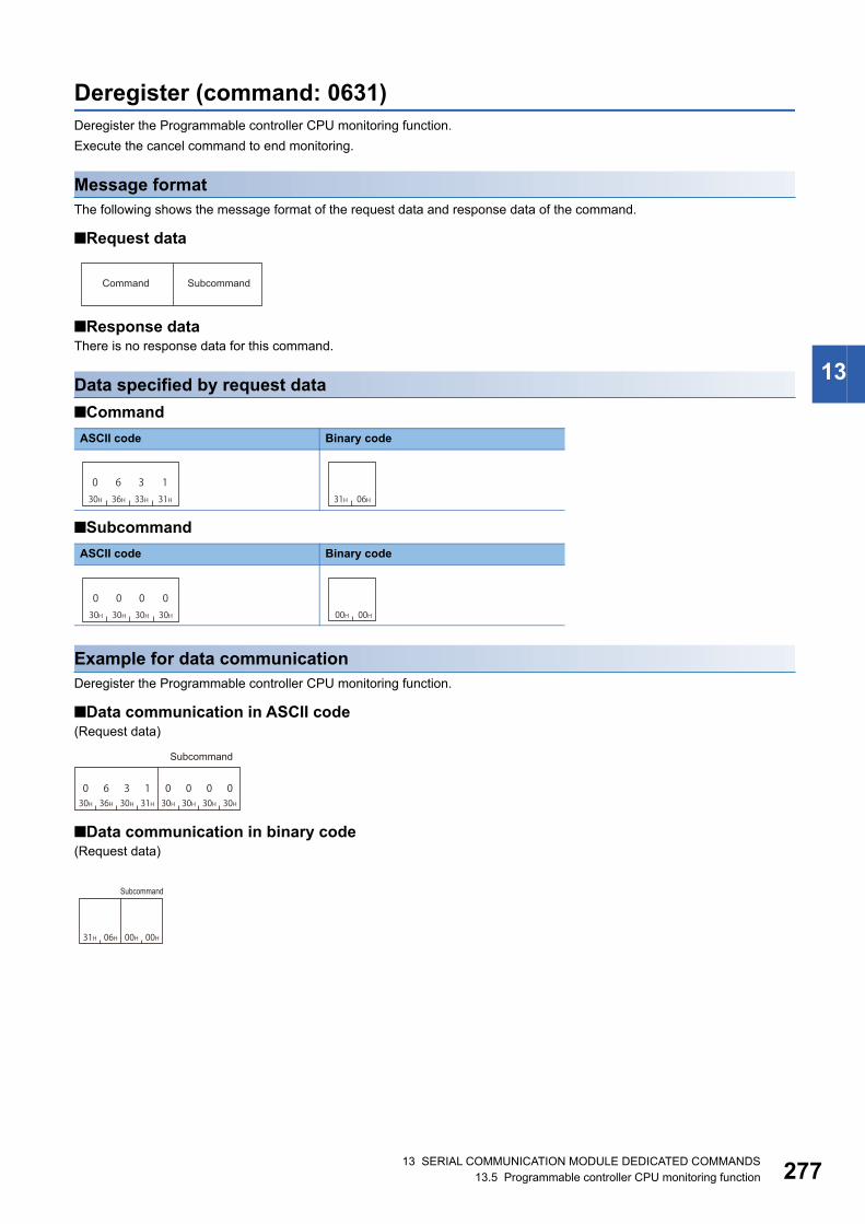
13 SERIAL COMMUNICATION MODULE DEDICATED COMMANDS13.5 Programmable controller CPU monitoring function 277
13
Deregister (command: 0631)Deregister the Programmable controller CPU monitoring function.
Execute the cancel command to end monitoring.
Message formatThe following shows the message format of the request data and response data of the command.
■Request data
■Response dataThere is no response data for this command.
Data specified by request data
■Command
■Subcommand
Example for data communicationDeregister the Programmable controller CPU monitoring function.
■Data communication in ASCII code(Request data)
■Data communication in binary code(Request data)
ASCII code Binary code
ASCII code Binary code
Command Subcommand
030H
636H
333H
131H 31H 06H
030H
030H
030H
030H 00H 00H
30H 36H 30H 31H 30H 30H 30H 30H00001360
Subcommand
31H 06H 00H 00H
Subcommand

27813 SERIAL COMMUNICATION MODULE DEDICATED COMMANDS13.6 On-demand function
13.6 On-demand functionOn-demand function is a function that transmits data to external device using MC protocol after starting up the function from
CPU module.
This function can be used to sent the emergency data that is required to notify to external devices from the CPU module.
The command can only be used for C24 connected to the external device on 1:1 basis. It cannot be used via
network.
If the on-demand function is used with multidrop connection of 1:n station or m:n station, the on-demand data
will be collapsed and proper data is not sent.
Settings for using the on-demand functionThe following shows the setting items for the on-demand function.
Settings of serial communication moduleSet the following values in the parameter of serial communication module or the buffer memory.
The execution result is stored in the following:
The setting content can be checked and changed by using any of the following Engineering tools.
• GX Works3 (Module parameter)
• GX Works2, GX Configurator-SC
For details on the setting items and buffer memory, refer to the following manuals.
• MELSEC iQ-R Serial Communication Module User's Manual(Application)
• MELSEC-Q/L Serial Communication Module User's Manual (Application)
Specification of interface to be sent and send dataSpecify the transmission channel (CH1/CH2) and data equivalent to the response data with the arguments of the following
dedicated instruction. Set the arguments in the program.
• G(P).ONDEMAND
For the dedicated instruction "G(P).ONDEMAND", refer to the following manuals.
• MELSEC iQ-R Programming Manual (Instructions, Standard Functions/Function Blocks)
• MELSEC-Q/L Serial Communication Module User's Manual (Application)
Setting item Description Corresponding buffer memory
CH1 CH2
Communication protocol setting Set the format of the message format to be used.
• MC protocol (Format 1) to MC protocol (Format 4): Data is sent by 1C frame
• MC protocol (Format 5): Data is send by 4C frame.
Word/byte units designation Set the unit of data length (number of data). 150 (96H) 310 (136H)
Buffer memory start address
designation
Set the start address of the buffer memory to be used for the on-demand
function.
160 (A0H) 320 (140H)
Data length designation Set the data length of the area to which the transmitted data is stored by the on-
demand function.
161 (A1H) 321 (141H)
Execution result Description Corresponding buffer memory
CH1 CH2
On-demand execution results • Normal completion: 0
• Abnormal completion (error code): Other than 0
598 (256H) 614 (266H)

13 SERIAL COMMUNICATION MODULE DEDICATED COMMANDS13.6 On-demand function 279
13
Execution procedureThe procedures for the on-demand function are as shown below.
Procedure for CPU module and C24The following shows the procedure to send data using the on-demand function from CPU module.
1. Set the items for the on-demand function.
Page 278 Settings for using the on-demand function
2. Execute the serial communication module dedicated instruction 'G (P). ONDEMAND'.
• MELSEC iQ-R Programming Manual (Instructions, Standard Functions/Function Blocks)
• MELSEC-Q/L Serial Communication Module User's Manual (Application)
Procedure for external deviceThe following shows the procedure to receive the data (on-demand data) transmitted using the on-demand function from CPU
module.
1. Receive the message.
2. Judge whether the received message is issued from the on-demand function by "PC No.".
For the message of on-demand function, 'PC No.' will be 'FE'. (Page 52 Network No., PC No.)
3. Process the received on-demand data.

28013 SERIAL COMMUNICATION MODULE DEDICATED COMMANDS13.6 On-demand function
Execution timingThe following shows the execution timing of send/receive processing while C24 is being sending/receiving other message of
MC protocol, when data transmission instruction by the on-demand function is executed in the CPU module.
When sending on-demand data or response data, the timeout check is performed by send monitoring timer
(timer 2). if a timeout error occurs, change the send monitoring time (timer 2).
When C24 is receiving request message of other command from external deviceC24 sends on-demand data before the response message to the external device is sent.
• Full-duplex communication: C24 sends on-demand data during the request message from the external device is being
received.
• Half-duplex communication: C24 sends on-demand data after the request message from the external device has been
received.
When C24 is sending response message of other command to external deviceC24 sends the on-demand data to the external device after the response message to the external device.
Message of the other command (Request message)
The C24 receives from the external device.
On-demand data (Response message)
Message of the other command (Response message)
The C24 transmits to the external device.
CPU moduleG(P).ONDEMANDG(P).ONDEMAND
Message of the other command (Request message)
The C24 receives from the external device.The C24 transmits to the external device.
On-demand data (Response message)
Message of the other command (Response message)
CPU moduleG(P).ONDEMAND
Message of the other command (Request message)
The C24 receives from the external device.
Message of the other command (Response message)
On-demand data (Response message)
The C24 transmits to the external device.
CPU moduleG(P).ONDEMAND

13 SERIAL COMMUNICATION MODULE DEDICATED COMMANDS13.6 On-demand function 281
13
On-demand (command: 2101)Send data using the on-demand function from CPU module. Any message other than send data is added automatically in the
message format selected in the communication protocol setting. ('FE' is specified to the 'PC No.' for the access route.)
• Communication protocol setting is MC protocol (Format 1) to MC protocol (Format 4): Message format of 1C frame
• Communication protocol setting is MC protocol (Format 5): Message format of 4C frame
When using 2C/3C/4C frame (Format 1 to 4), register the message format of each format in the user frame.
Page 29 Message Formats of Each Protocol
For the user frames, refer to the following manuals.
• MELSEC iQ-R Serial Communication Module User's Manual(Application)
• MELSEC-Q/L Serial Communication Module User's Manual (Application)
Message formatThe following shows the message format of the request data and response data of the command.
■Request dataThere is no request data for this command.
■Response data
Data stored in response data
■CommandIt is added only when the message is sent with MC protocol format 5 specified in the communication protocol setting.
■Transmission dataThe transmission data specified in the dedicated instruction 'G(P).ONDEMAND' is stored.
The order of data differ depending on the setting of "Word/byte units designation" in Engineering tool.
For byte units, regard the word data as 2-byte data and send numerical values from lower byte (L: bits 0 to 7).
Ex.
When transmitting 2-word data (1234H, 5678H)
• Word unit (0)
• Byte unit (1)
Binary code
ASCII code Binary code
ASCII code Binary code
Command Transmission data
01H 21H
1 2 331H 32H 33H
434H
5 6 735H 36H 37H
8 38H 12H 34H 56H 78H
3 4 133H 34H 31H
232H
7 8 537H 38H 35H
6 36H 34H 12H 78H 56H

28213 SERIAL COMMUNICATION MODULE DEDICATED COMMANDS13.6 On-demand function
Communication example (communication protocol setting is format 1 to 4)Send 2-word data (1234H, 5678H) to the external device from the CPU module under the following settings.
• Communication protocol setting: MC protocol (Format 1 to 4)
• Word/byte units designation: Word unit
(Response data)
Communication example (communication protocol is format 5)Send 2-word data (1234H, 5678H) to the external device from the CPU module under the following settings.
• Communication protocol setting: MC Protocol (Format 5)
• Word/byte units designation: Word unit
(Response data)
1 2 331H 32H 33H
434H
5 6 735H 36H 37H
8 48H
Transmission data
01H 21H 12H 34H 56H 78H
Command Transmission data

283
PA
RT
4
PART 4 COMPATIBILITY WITH QnA SERIES
This part explains the specifications when using MELSEC-QnA series devices.
14 MELSEC-QnA SERIES SUPPORTED SPECIFICATIONS
15 QnACPU DEDICATED COMMANDS

28414 MELSEC-QnA SERIES SUPPORTED SPECIFICATIONS14.1 Frames and Commands that can be used
14 MELSEC-QnA SERIES SUPPORTED SPECIFICATIONS
This chapter explains the specifications of the messages of MC protocol and accessible ranges when using the MELSEC-
QnA series devices as follows:
• When accessing system including MELSEC-QnA series modules
• When utilizing software for data communication created for MELSEC-QnA series programmable controller.
14.1 Frames and Commands that can be usedWhen accessing MELSEC-QnA series modules, all frames of MC protocol can be used.
However, the commands that can be used have some restrictions. (Page 469 Accessible Modules for Each Command)
QnA-compatible frameThe following frames have compatibility with the message protocol and the message format for MELSEC-QnA series.
14.2 Accessible ModulesAccessible to the following MELSEC-QnA series modules within the access range.
Accessible modules to other stationsThe following modules of other station can be accessed.
Modules that can be relayed between networksThe following shows the modules that can be relayed between networks when accessing a MELSEC-QnA series module.
■MELSEC-QnA series modules
*1 QnA series Ethernet interface modules can be relayed between networks when using the module with the function version B or later. Check the function version with the production date printed on the rating plate on the side of the module.(Manufactured date: Year (lower two digits), Month (two digits), function version (one digit))
Frame Compatible message format Accessible range
4C frame Dedicated protocols for MELSEC-QnA series serial communication modules
(QnA extension frame)
Page 45 Accessible range of 4C frame
3C frame Dedicated protocols for MELSEC-QnA series serial communication modules
(QnA frame)
Page 46 Accessible range of 3C frame
2C frame Dedicated protocols for MELSEC-QnA series serial communication modules
(QnA simplified frame)
Page 46 Accessible range of 2C frame
3E frame Message formats for MELSEC-QnA series Ethernet interface modules Page 48 Accessible range of 4E frame, 3E frame
Type Model name
CPU module Q2ACPU, Q2ACPU-S1, Q2ASCPU, Q2ASCPU-S1, Q2ASHCPU, Q2ASHCPU-S1, Q3ACPU, Q4ACPU
Redundant system Q4ARCPU
MELSECNET/10 remote I/O AJ72QLP25(G), AJ72QBR15, A1SJ72QLP25, A1SJ72QBR15
Special function module Refer to the following section.
Page 156 Accessible modules
Network Model name
MELSECNET/10 QJ71LP21, QJ71LP21-25, QJ71LP21S-25, QJ71LP21G, QJ71BR11 (MELSECNET/10 mode)
AJ71QLP21 (S/G), AJ71QBR11, A1SJ71QLP21 (S), A1SJ71QBR11
Ethernet*1 AJ71QE71N3-T, AJ71QE71N-B5, AJ71QE71N-B2, AJ71QE71N-T, AJ71QE71N-B5T, A1SJ71QE71N3-T,
A1SJ71QE71N-B5, A1SJ71QE71N-B2, A1SJ71QE71N-T, A1SJ71QE71N-B5T, AJ71QE71, AJ71QE71-B5,
A1SJ71QE71-B2, A1SJ71QE71-B5

14 MELSEC-QnA SERIES SUPPORTED SPECIFICATIONS14.3 Considerations 285
14
■Modules other than MELSEC-QnA series
Page 21 Modules that can be relayed between networks
14.3 ConsiderationsThe following shows the considerations when using MELSEC-QnA series devices.
Considerations when connecting E71
■Setting range of monitoring timer When accessing QnACPU for the first time, the wait time for CPU monitoring timer is required before receiving a response
message because QnACPU identifies the CPU type. Be sure to set a value within the setting range shown below.
Network Module type Model
CC-Link IE Field Network CC-Link IE Field Network master/
local module
LJ71GF11-T2, QJ71GF11-T2, QS0J71GF11-T2
CC-Link IE Controller Network CC-Link IE Controller Network
module
QJ71GP21-SX, QJ71GP21S-SX
MELSECNET/H MELSECNET/H module QJ71LP21, QJ71LP21-25, QJ71LP21S-25, QJ71LP21G, QJ71BR11,
QJ71NT11B
Ethernet Ethernet interface module LJ71E71-100, QJ71E71-100, QJ71E71-B5, QJ71E71-B2, QJ71E71
Access target Monitoring timer
Connected station (host station) 1H to 28H (0.25 s to 10 s)
Other station 2H to F0H (0.5 s to 60 s)
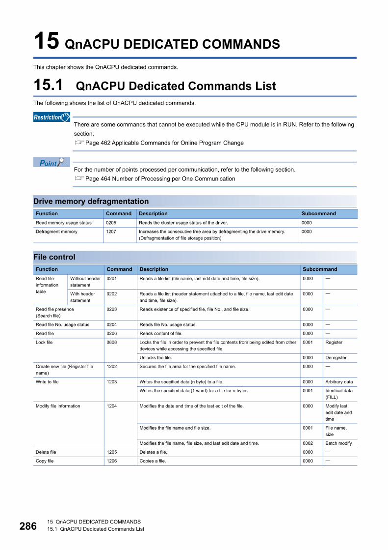
28615 QnACPU DEDICATED COMMANDS15.1 QnACPU Dedicated Commands List
15 QnACPU DEDICATED COMMANDS
This chapter shows the QnACPU dedicated commands.
15.1 QnACPU Dedicated Commands ListThe following shows the list of QnACPU dedicated commands.
There are some commands that cannot be executed while the CPU module is in RUN. Refer to the following
section.
Page 462 Applicable Commands for Online Program Change
For the number of points processed per communication, refer to the following section.
Page 464 Number of Processing per One Communication
Drive memory defragmentation
File control
Function Command Description Subcommand
Read memory usage status 0205 Reads the cluster usage status of the driver. 0000
Defragment memory 1207 Increases the consecutive free area by defragmenting the drive memory.
(Defragmentation of file storage position)
0000
Function Command Description Subcommand
Read file
information
table
Without header
statement
0201 Reads a file list (file name, last edit date and time, file size). 0000
With header
statement
0202 Reads a file list (header statement attached to a file, file name, last edit date
and time, file size).
0000
Read file presence
(Search file)
0203 Reads existence of specified file, file No., and file size. 0000
Read file No. usage status 0204 Reads file No. usage status. 0000
Read file 0206 Reads content of file. 0000
Lock file 0808 Locks the file in order to prevent the file contents from being edited from other
devices while accessing the specified file.
0001 Register
Unlocks the file. 0000 Deregister
Create new file (Register file
name)
1202 Secures the file area for the specified file name. 0000
Write to file 1203 Writes the specified data (n byte) to a file. 0000 Arbitrary data
Writes the specified data (1 word) for a file for n bytes. 0001 Identical data
(FILL)
Modify file information 1204 Modifies the date and time of the last edit of the file. 0000 Modify last
edit date and
time
Modifies the file name and file size. 0001 File name,
size
Modifies the file name, file size, and last edit date and time. 0002 Batch modify
Delete file 1205 Deletes a file. 0000
Copy file 1206 Copies a file. 0000

15 QnACPU DEDICATED COMMANDS15.2 Defragmentation of Drive Memory 287
15
15.2 Defragmentation of Drive MemoryAn external device performs the following functions for other station QnACPU drive which stores parameters and program
files that the sequence programs are written.
Read drive memory usage statusCheck the usage status of the drive memory (cluster usage status) of the specified drive.
Defragment drive memoryWhen the valid data written in the drive memory is not consecutive, increase the consecutive free area in cluster unit by
defragmentation.
A cluster is the minimum unit when files are stored to drive memory (such as memory card) and the memory
containing data is managed by FAT*1.
The size of one cluster of each QnACPU drive is as follows:
• Internal memory : 4096 bytes
• Other memory : 512 bytes
For example, if a data less than 512 bytes is written to a memory card, one cluster of drive memory is used to
write the data.
If 513 to 1024 bytes of data are written, two clusters of drive memory is used to write the data.
*1 An abbreviation for 'File Allocation Table'. A table used by the operating system to manage the location of files on the drive memory.
■Images of drive memory defragmentation: Cluster in not used (empty), : Cluster is being used (valid data is written in it)
• Before drive memory defragmentation
• After drive memory defragmentation
*1 16th cluster from the head cluster*2 First cluster*3 Last cluster
Cluster b15 b14 b13 b12 b11 b10 b9 b8 b7 b6 b5 b4 b3 b2 b1 b0
First 16 clusters *1 *2
Last 16 clusters *3
Cluster b15 b14 b13 b12 b11 b10 b9 b8 b7 b6 b5 b4 b3 b2 b1 b0
First 16 clusters *1 *2
Last 16 clusters *3

28815 QnACPU DEDICATED COMMANDS15.2 Defragmentation of Drive Memory
Data to be specified in commandsThe following explains the data to be specified in commands when an external device performs defragmentation to the drive
memory of QnACPU.
KeywordA data to allow/prohibit the access to the drive, which is the character string (up to 6 characters) that are registered to the
specified drive.
When a keyword has already registered, specify the same keyword.
■Data communication in ASCII codeUse the keyword registered in the specified drive and send as is.
■Data communication in binary codeConvert the keyword registered in the specified drive to 3-byte binary code, and send it from lower byte (L: bits 0 to 7).
Ex.
When the registered keyword is '012345'
Ex.
When the keyword registered is '012300'
■The content of data when a keyword is not registered in a specified drive • Data communication in ASCII code: '000000'
• Data communication in binary code: '00H', '00H', '00H'
Setting flagA data that indicates whether the keyword registered to the specified drive is specified to the keyword above.
■Data communication in ASCII codeConvert the numerical value to 2-digit ASCII code (hexadecimal), and send it from the upper digits.
■Data communication in binary codeSend a 1-byte numerical value.
■Setting flag to be specified
Values converted to binary code Transmission order
01H, 23H, 45H 45H, 23H, 01H
Values converted to binary code Transmission order
01H, 23H, 00H 00H, 23H, 01H
Setting value Content to be specified
00H Keyword is invalid (specify a dummy)
01H Keyword is enabled (specify the keyword registered in the specified drive).
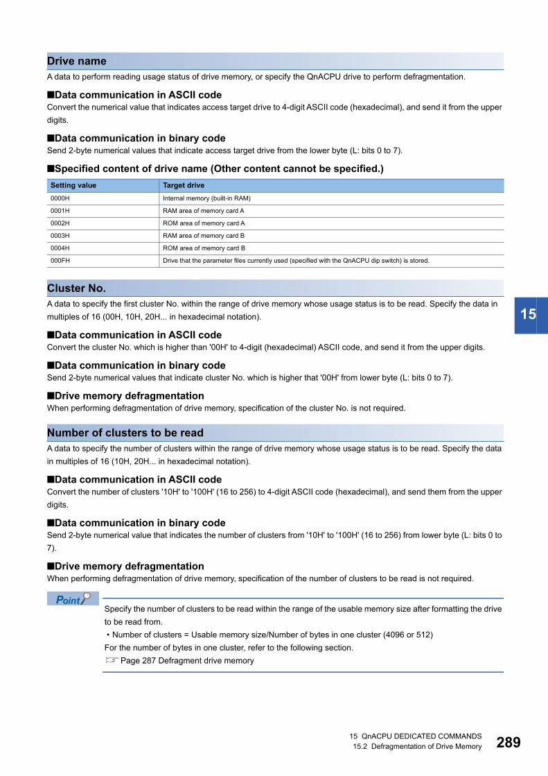
15 QnACPU DEDICATED COMMANDS15.2 Defragmentation of Drive Memory 289
15
Drive nameA data to perform reading usage status of drive memory, or specify the QnACPU drive to perform defragmentation.
■Data communication in ASCII codeConvert the numerical value that indicates access target drive to 4-digit ASCII code (hexadecimal), and send it from the upper
digits.
■Data communication in binary codeSend 2-byte numerical values that indicate access target drive from the lower byte (L: bits 0 to 7).
■Specified content of drive name (Other content cannot be specified.)
Cluster No.A data to specify the first cluster No. within the range of drive memory whose usage status is to be read. Specify the data in
multiples of 16 (00H, 10H, 20H... in hexadecimal notation).
■Data communication in ASCII codeConvert the cluster No. which is higher than '00H' to 4-digit (hexadecimal) ASCII code, and send it from the upper digits.
■Data communication in binary codeSend 2-byte numerical values that indicate cluster No. which is higher that '00H' from lower byte (L: bits 0 to 7).
■Drive memory defragmentationWhen performing defragmentation of drive memory, specification of the cluster No. is not required.
Number of clusters to be readA data to specify the number of clusters within the range of drive memory whose usage status is to be read. Specify the data
in multiples of 16 (10H, 20H... in hexadecimal notation).
■Data communication in ASCII codeConvert the number of clusters '10H' to '100H' (16 to 256) to 4-digit ASCII code (hexadecimal), and send them from the upper
digits.
■Data communication in binary codeSend 2-byte numerical value that indicates the number of clusters from '10H' to '100H' (16 to 256) from lower byte (L: bits 0 to
7).
■Drive memory defragmentationWhen performing defragmentation of drive memory, specification of the number of clusters to be read is not required.
Specify the number of clusters to be read within the range of the usable memory size after formatting the drive
to be read from.
• Number of clusters = Usable memory size/Number of bytes in one cluster (4096 or 512)
For the number of bytes in one cluster, refer to the following section.
Page 287 Defragment drive memory
Setting value Target drive
0000H Internal memory (built-in RAM)
0001H RAM area of memory card A
0002H ROM area of memory card A
0003H RAM area of memory card B
0004H ROM area of memory card B
000FH Drive that the parameter files currently used (specified with the QnACPU dip switch) is stored.

29015 QnACPU DEDICATED COMMANDS15.2 Defragmentation of Drive Memory
Free cluster tableA data indicating the status of cluster usage. It is a response data to 'read drive memory usage status' (command: 0205).
■Data communication in ASCII codeThe numerical value that indicates usage status is converted to n-digit (hexadecimal) ASCII code and sent to the external
device. (16 clusters/4 digits)
■Data communication in binary codeAn m-byte numerical value that indicates usage status is sent to the external device. (16 clusters/2 bytes)
■Content of free cluster tableThe usage status of each cluster is indicated by one cluster per bit.
Ex.
0: Empty, 1: Used
*1 16th cluster from the head cluster*2 First cluster*3 Last cluster
When the usage status is as shown above, the content of free cluster table that is returned to the external device is as follows:
• When 32 clusters are returned while communicating in ASCII code
'3CFF003F' is returned and it is sent from '3'.
• When 32 clusters are returned while communicating in binary code
'FFH', '3CH', '3FH', and '00H' are returned and these are sent from 'FFH'.
■Drive memory defragmentationWhen performing defragmentation of drive memory, the free cluster table is not returned.
Cluster b15 b14 b13 b12 b11 b10 b9 b8 b7 b6 b5 b4 b3 b2 b1 b0 Values for 16 bits
First 16 clusters 0*1 0 1 1 1 1 0 0 1 1 1 1 1 1 1 1*2 3CFFH
0 0 0 0 0 0 0 0 0 0 1 1 1 1 1 1 003FH
0 0 0 0 0 0 0 0 0 0 0 0 0 0 0 0 0000H
Last 16 clusters 0*3 0 0 0 0 0 0 0 0 0 0 0 0 0 0 0 0000H

15 QnACPU DEDICATED COMMANDS15.2 Defragmentation of Drive Memory 291
15
Read drive memory usage status (command: 0205)Read the usage status of the drive memory.
When creating a new file (registering new file), a consecutive free area for the file size to be created is
required.
To calculate the capacity (size) of the consecutive free area of the specified drive, check the number of
consecutive free clusters (number of consecutive OFF bits) by reading the usage status of that drive memory.
Capacity of consecutive free area (size) = number of consecutive free cluster 4096 or 512 (byte)
When the consecutive area is insufficient, perform the following memory defragmentation.
Page 293 Defragment drive memory (command: 1207)
Message formatThe following shows the message format of the request data and response data of the command.
■Request data
■Response dataThe free cluster table is stored. The order of data differs depending on the ASCII code or binary code.
Page 290 Free cluster table
Data specified by request data
■Command
■Subcommand
■KeywordSet whether to allow/prohibit access to a drive. (Page 296 Keyword)
■Setting flagThis indicates whether the keyword registered in the specified drive matches the keyword of request data. (Page 288
Setting flag)
■Drive nameRead the usage status of the drive memory, and specify the QnACPU drive to be defragmented. (Page 289 Drive name)
■Cluster No.Specify the first cluster No. within the range of drive memory whose usage status is to be read. (Page 289 Cluster No.)
ASCII code Binary code
ASCII code Binary code
0 2 0 530H 32H 30H 35H
05H 02H
ASCII
Subcommand Keyword Setting flag Drive name Cluster No.Number of clusters to
be read
Binary
Setting flag Keyword Drive name Cluster
No.Number of clusters to be read
Subcommand
030H
232H
030H
535H 05H 02H
030H
030H
030H
030H 00H 00H

29215 QnACPU DEDICATED COMMANDS15.2 Defragmentation of Drive Memory
■Number of clusters to be readSpecify the number of clusters within the range of drive memory whose usage status is to be read. (Page 289 Number of
clusters to be read)
Communication exampleRead the usage status of the drive memory of the RAM area in a memory card A (drive name: 01H) for 32 clusters.
■Data communication in ASCII code(Request data)
(Response data)
■Data communication in binary code(Request data)
(Response data)
0 2 0 530H 32H 30H 35H
0 0 030H 30H 30H
030H 30H
1 3 432H 33H 34H
5 0 135H 30H 31H
0 0 030H 30H 30H
131H
0 0 030H 30H 30H
030H
0 0 230H 30H 32H
030H
0 231H
Keyword Setting flagSubcommand Drive name Cluster No. Number of clusters to be read
Free cluster tableCluster No.0 to 15 Cluster No.16 to 31
05H 00H 01H 01H 01H 00H 00H 20H02H 00H 45H 23H 00H 00H
Setting flag Cluster No.
Keyword Drive nameNumber of
clusters to be readSubcommand
Free cluster tableCluster No.0 to 15
Cluster No.16 to 31

15 QnACPU DEDICATED COMMANDS15.2 Defragmentation of Drive Memory 293
15
Defragment drive memory (command: 1207)Perform the defragmentation of drive memory.
Perform the defragmentation of drive memory in the following situation.
• When the specified QnACPU is STOP.
• The usage status of drive memory (check with command 0205) is not consecutive and the files cannot be stored.
Message formatThe following shows the message format of the request data and response data of the command.
■Request data
■Response dataThere is no response data for this command.
In the following cases, an error occurs and an abnormal response will be returned.
• When QnACPU is protected by system protection.
• When the keyword registered in the specified drive is not specified.
• When the drive memory is faulty (defective cluster, etc.).
• When the subdirectory is created by using an IC memory card read/writer.
• When the file is not stored in one consecutive area by using an IC memory card read/writer.
Data specified by request data
■Command
■Subcommand
■KeywordSet whether to allow/prohibit access to a drive. (Page 296 Keyword)
■Setting flagThis indicates whether the keyword registered in the specified drive matches the keyword of request data. (Page 288
Setting flag)
■Drive nameRead the usage status of the drive memory, and specify the QnACPU drive to be defragmented. (Page 289 Drive name)
ASCII code Binary code
ASCII code Binary code
ASCII
Subcommand Keyword Setting flag Drive name
Binary
Setting flag Keyword Drive nameSubcommand
131H
232H
030H
737H 07H 12H
030H
030H
030H
030H 00H 00H
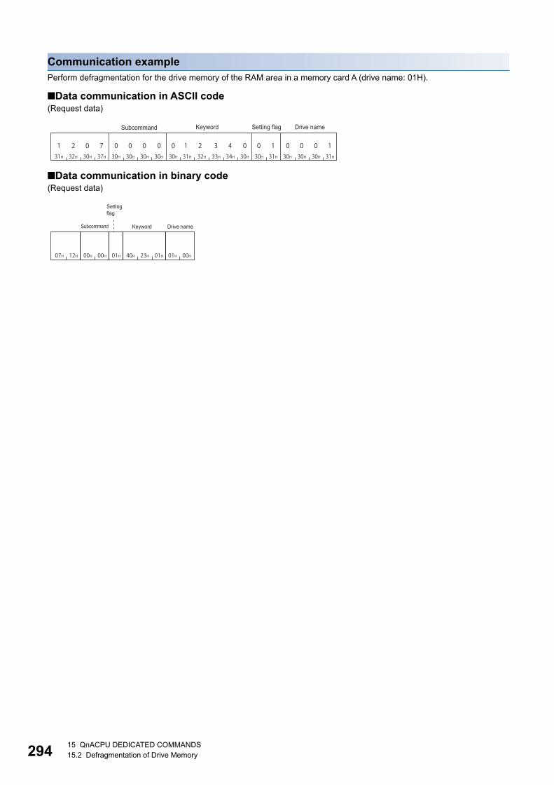
29415 QnACPU DEDICATED COMMANDS15.2 Defragmentation of Drive Memory
Communication examplePerform defragmentation for the drive memory of the RAM area in a memory card A (drive name: 01H).
■Data communication in ASCII code(Request data)
■Data communication in binary code(Request data)
1 2 0 731H 32H 30H 37H
0 0 030H 30H 30H
030H 30H
1 3 432H 33H 34H
0 0 130H 30H 31H
0 0 030H 30H 30H
131H
0 231H
Keyword Setting flagSubcommand Drive name
07H 12H 00H 00H 01H 40H 23H 01H 01H 00H
Setting flag
Keyword Drive nameSubcommand

15 QnACPU DEDICATED COMMANDS15.3 File Control 295
15
15.3 File ControlRead, register, and delete files in QnACPU modules.
Use this function in the following situations:
• Read parameters and sequence programs from an external device
• Write the files read from CPU module to an external device according to the commands.
For the file name, extension, and location of a file stored in CPU module, refer to the user's manual (function explanation,
program fundamentals) of the CPU module used.
Considerations for file controlThe following are the considerations when managing files in QnACPU.
Editing filesThe files read from CPU module are used for storage on an external device.
The external device cannot edit the content of a file read from CPU module.
Data read/writeWhen the data of the entire file size cannot be read/written in a single communication, use several communications to read/
write the data.
The file size can be verified using the following functions.
System protectionIf the CPU module is protected by system protection when using the following functions, an error occurs and an abnormal
completion message is returned.
Registration of keywordWhen registering a keyword in the file, keep the registered keyword.
When accessing the following files, specifying the registered keyword when opening or reading/writing to that file is required.
• Parameter file
• Program files
File attributeThe file attribute is valid only when the following functions are used. For other commands, the attribute is handled as a
dummy.
Function Reference
Read file information table function Page 306 Read file information table without header statement (command: 0201)
Page 309 Read file information table with header statement (command: 0202)
Read file presence function Page 312 Read file presence (Search file) (command: 0203)
Function Reference
Create new file (Register file name) Page 321 Create new file (Register file name) (command: 1202)
Write to file Page 323 Write to file (command: 1203)
Delete file Page 333 Delete file (command: 1205)
Copy file Page 335 Copy file (command: 1206)
Modify file information (date created, attribute) Page 327 Modify file information (command: 1204)
Function Reference
Read file information table function Page 306 Read file information table without header statement (command: 0201)
Page 309 Read file information table with header statement (command: 0202)
Create new file (Register file name) Page 321 Create new file (Register file name) (command: 1202)
Modify file information (date created, attribute) Page 327 Modify file information (command: 1204)

29615 QnACPU DEDICATED COMMANDS15.3 File Control
Data to be specified in commandsThis section explains the data to be specified in command when an external device manages files in the CPU module.
KeywordAllow/prohibit the access to the specified drive.
When a keyword has already been registered, specify the same keyword.
For the content of the data, refer to the following section.
Page 288 Keyword
Setting flagA data that indicates whether the keyword registered to the specified drive is specified to the keyword above.
For the content of the data, refer to the following section.
Page 288 Setting flag
Drive name, Drive No.A data to specify the drive in a CPU module of which files are to be managed.
For the method on how to specify the drive name and its corresponding drive, refer to the following section.
Page 289 Drive name
File No.A value to specify the registered number when a file specified by file name and extension is registered (written) to CPU
module, or the registration number when registering to CPU module.
■Data communication in ASCII codeConvert the file No. to 4-digit ASCII code (hexadecimal), and send it from the upper digits.
■Data communication in binary codeSend the 2-byte*1 value that indicates file No. from the lower byte (L: bits 0 to 7).
*1 For C24, the additional code may be added. (Page 35 Additional code (10H))
Ex.
1FH
■Specified content of file No.
The file No. of the registered file can be checked using the following functions.
Page 306 Read file information table without header statement (command: 0201)
Page 309 Read file information table with header statement (command: 0202)
Page 312 Read file presence (Search file) (command: 0203)
The unused file No. at registering new file can be checked using the following function.
Page 314 Read file No. usage status (command: 0204)
ASCII code Binary code
Value to be specified Description Content to be specified
01H to 100H File No. Specify when the file No. is known.
FFFFH File No. unknown Specify when C24/E71 searches for file No.
(The request to read/write data from/to C24/E71 will be delayed for more than
one sequence scan time.)
030H
030H
131H
F46H 1FH 00H

15 QnACPU DEDICATED COMMANDS15.3 File Control 297
15
Number of requested file, total number of registered files, number of file informationA data that indicates the number of request files, number of files registered in the specified drive, and number of files that
return file information when reading file information.
■Data communication in ASCII codeConvert the numerical value described in the reference section relevant to the corresponding function to 4-digit ASCII code
(hexadecimal), and send it from the upper digits.
■Data communication in binary codeSend the 2-byte numerical value described in the reference section relevant to the corresponding function from each low byte
(L: bits 0 to 7).
File name, extension, and attribute
■For file name, extension, and storage location that can be specifiedFor file name, extension, and storage location of files that can be specified in CPU modules, refer to the user's manual
(function explanation, program fundamentals) of the CPU module used.
Files not described in the user's manual (function explanation, program fundamentals) of the CPU module
used may also be shown for file control. Do not access them since they are for the system use.
■When creating files or changing the file namesWhen creating a new file or changing the file name, specify the file name (up to 8 characters) and extension (3 characters) in
accordance with the file naming rule of Engineering tool.
■File name, extensionFor QnACPU, specify the file name by a file name + extension.
Ex.
When the file name is 'ABC.QPG'
File name: ABC QPG ( indicates a space)
■AttributeAdd an attribute a file.
Specify the attribute with 1 byte.
Specify '20H' as an attribute value (disk files that can be read/written) at a new file creation and when a dummy is specified.
When the attribute of the created file is not changed, the attribute of readable/writable disk file will be attached.
The attributes for the existing files can be checked using the following functions.
Page 306 Read file information table without header statement (command: 0201)
Page 309 Read file information table with header statement (command: 0202)
The attribute of the created files can be changed between '01H' (Read Only file) '20H' (readable/writable
disk file).
Page 327 Modify file information (command: 1204)
Item Specification method
File name Specify the file name within 8 characters.
If the file name is less than 8 characters, add space (code: 20H) after the file name and fill the characters to 8
characters.
Extension Specify the extension within 3 characters.

29815 QnACPU DEDICATED COMMANDS15.3 File Control
Last edit time and last edit dateA data that indicates the date and time when the current file content was registered.
■Data communication in ASCII codeConvert the numerical value to a 4-digit (hexadecimal) ASCII code and send it from upper digits (time, year). When dummy is
specified, send '0000H'.
■Data communication in binary codeSend 2-byte numerical value from lower bytes (L: bits 0 to 7). When dummy is specified, send '0000H'.
■Date (year, month, day)Specify year, month , and day with 16-bit value.
• Year: The binary value is represented with bits 9 to 15 by setting the year 1980 to '0'. *1
• Month: Specify the binary value in bit 5 to 8.
• Day: Specify the binary value in bit 0 to 4.
*1 This indicates incremental number of year by regarding 1980 as '0'.
Ex.
April 1st, 2010
■Time (hour, minute, second)Represent hour, minute, and second with 16-bit value.
• Hour: Represent binary value with bit 11 to 15.
• Minute: Represent binary value with bit 5 to 10.
• Second: Represent binary value 2 with bit 0 to 4.
Ex.
When 20:50:58
ASCII code Binary code
ASCII code Binary code
0 0 1 1 1 1 0 0 1 0 0 0 0 0 0 1b9 b8 b4 b0b5b15
1EH(30) 4H(4) 1H(1)
3H CH 8H 1H
(Year) (Month) (Day)
Numerical values in relevant range
30+1980 = 2010
Numerical values for 4 bits
333H
C43H
838H
131H 81H 3CH
AH 6H 5H DH
1 0 1 0 0 1 1 0 0 1 0 1 1 1 0 1
b4 b0b10 b5b15 b11
14H(20) 32H(50) 1DH(29)
58÷2=29
(Hours) (Minutes) (Second)
Numerical values in relevant range
Numerical values for 4 bits
A41H
636H
535H
D44H 5DH A6H

15 QnACPU DEDICATED COMMANDS15.3 File Control 299
15
File sizeA data that indicates the current file size in number of bytes.
■Data communication in ASCII codeConvert the numerical value to 8-digit (hexadecimal) ASCII code, and send it from the upper digits.
■Data communication in binary codeSend 4-byte*1 numerical from the lower byte (L: bits 0 to 7).
*1 For C24, the additional code may be added. (Page 35 Additional code (10H))
Ex.
When the file size is 7168 bytes
Header statementA header statement given to the file specified by Engineering tool supporting QnACPU (up to 32 characters).
■Data communication in ASCII codeSend data from the first character.
If the header statement is less than 32 characters, append a space (code: 20H).
Ex.
The header statement at the registration is '1 line-PC5'
The header statement becomes '1 line-PC5...' , and is sequentially sent from '1'. (: indicating a space.)
■Data communication in binary codeUse the character code of header statement as binary value, and send if from the first character.
When the header statement is less than 32 characters, 20H is added for the shortage.
Ex.
The header statement at registration is '1 line-PC5'
The header statement becomes 31H, 20H, 6CH, 69H, 6EH, 65H, 2DH, 50H, 43H, 35H, 20H, 20H..., and is sequentially sent
from 31H.
Offset addressA data to specify the start address of the file range for which data is read and written.
Specify the address (one address/one byte) from the head (offset address: 0H) of each file with an even number.
■Data communication in ASCII codeConvert the address described in the reference section relevant to the corresponding function to 8-digit (hexadecimal) ASCII
code, and send it from the upper digits.
■Data communication in binary codeSend 4-byte numerical values described in the reference section relevant to the corresponding function from lower byte (L:
bits 0 to 7).
■Offset addresses that can be specifiedCheck the file size (number of bytes) with the following read file information table functions, and calculate the offset address
(0H to nH) by the size.
Page 306 Read file information table without header statement (command: 0201)
Page 309 Read file information table with header statement (command: 0202)
ASCII code Binary code
30H 30H 30H 30H 31H 43H 30H 30H
0 0 0 00 1 C 000H 1CH 00H 00H

30015 QnACPU DEDICATED COMMANDS15.3 File Control
Number of bytes read, number of bytes writtenA data to specify the number of bytes in the file range from/to which data is read/written. Specify it as one address per one
byte.
■Data communication in ASCII codeConvert the numerical value described in the reference section of the relevant function to 4-digit ASCII code (hexadecimal),
and send it from the upper digits.
■Data communication in binary codeSend 2-byte numerical value described in the reference section of the relevant function from the lower byte (L: bits 0 to 7).
Read data, write data (for batch read and batch write functions)A data read from or to be written to the file in the CPU module.
■Data communication in ASCII codeConvert one byte (one address) to 2-digit ASCII code (hexadecimal), and send it for the specified number of bytes from the
upper digits.
■Data communication in binary codeSend the specified number of bytes as one byte for one address.
■Data order • When reading data: Store the data to the external device without changing the order of data read from the CPU module.
• When writing data: Specify the data without changing the order of data read from CPU module.
Write data (identical data write function)A data for the identical data write function used to wrote the identical data to the existing QnACPU files.
■Data communication in ASCII codeConvert the numerical value for one word to 4-digit ASCII code (hexadecimal), and send it from the upper digits.
■Data communication in binary codeSend the numerical value for one word from the lower byte (L: bits 0 to 7).
CapacityA data to reserve the file area on the specified disk when registering a new file. Specify the data in the number of bytes.
■Data communication in ASCII codeConvert the numerical value which represents the area for specified file to be reserved in 2 words to 8-digit ASCII code
(hexadecimal), and send it from the upper digits.
■Data communication in binary codeSend the numerical value which represents the area for the specified file to be reserved in 2 words from the lower byte (L: bits
0 to 7).
A new file with the same contents as the existing file can be registered from an external device.
The size of the relevant existing file must be checked using the read file information table function.
Page 306 Read file information table without header statement (command: 0201)
Page 309 Read file information table with header statement (command: 0202)
Page 312 Read file presence (Search file) (command: 0203)

15 QnACPU DEDICATED COMMANDS15.3 File Control 301
15
Fixed valueSpecify '0'.
Modification pattern (for changing file name and file size)A data to specify which information to be modified when information (file name, size, date and time created) of the existing file
is modified.
■Data communication in ASCII codeConvert the numerical value to 4-digit ASCII code (hexadecimal), and send it from the upper digits.
■Data communication in binary codeSend 2-byte numerical value from the low byte (L: bits 0 to 7).
■Specified value and contents of modification pattern
■Modifying the file creation date and time (command: 1204, subcommand: 0000)04H, 08H, 0CH, 14H, 18H, or 1CH can be specified with 16 bits.
■Modifying the file name and file size (command: 1204, subcommand: 0001)01H, 02H, 03H, 20H, 21H, 22H, or 23H can be specified with 16 bits.
■Modifying the file information in batch (command: 1204; subcommand: 0002)The range from 01H to 3FH can be specified with 16 bits.
ASCII code Binary code
Bit Description Value to be specified
b0 File name and extension
specification existence
0: Do not modify the file name and extension, 1: Modify the file name and extension
b1 File attribute modification
specification existence
0: Do not modify the attribute, 1: Modify the attribute
b2 Last edit time modification
specification existence
0: Do not modify the last edit time, 1: Modify the last edit time
b3 Last edit date modification
specification existence
0: Do not modify the last edit date, 1: Modify the last edit date
b4 Modification mode for date and time
specification
When modifying date or time, specify which data to use.
0: Use date and time in a message, 1: Use date and time of QnACPU (specify dummy date and time in the
message)
b5 File size modification specification
existence
0: Do not modify the file size, 1: Modify the file size
b6 to
b15
(fixed to '0')
Bit string b15 b14 b13 b12 b11 b10 b9 b8 b7 b6 b5 b4 b3 b2 b1 b0
Specification range 0 0 0 0 0 0 0 0 0 0 0 1/0 1/0 1/0 0 0
Bit string b15 b14 b13 b12 b11 b10 b9 b8 b7 b6 b5 b4 b3 b2 b1 b0
Specification range 0 0 0 0 0 0 0 0 0 0 1/0 0 0 0 1/0 1/0
Bit string b15 b14 b13 b12 b11 b10 b9 b8 b7 b6 b5 b4 b3 b2 b1 b0
Specification range 0 0 0 0 0 0 0 0 0 0 1/0 1/0 1/0 1/0 1/0 1/0
030H
030H
030H
030H 00H 00H
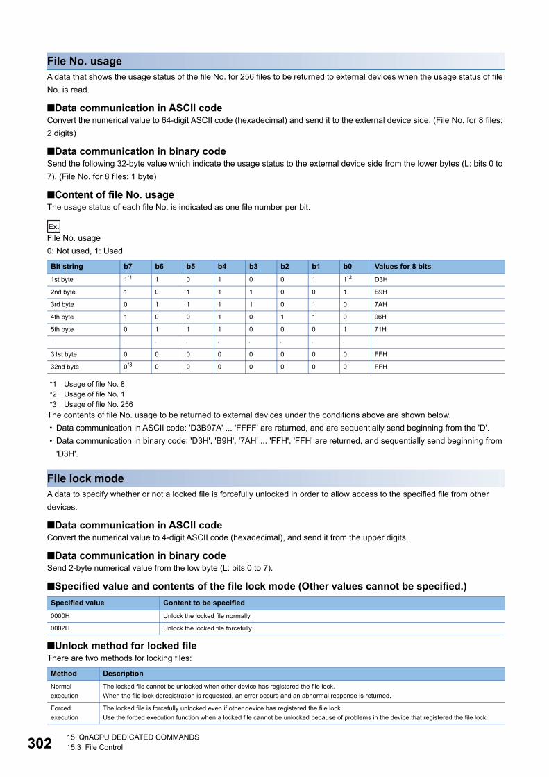
30215 QnACPU DEDICATED COMMANDS15.3 File Control
File No. usageA data that shows the usage status of the file No. for 256 files to be returned to external devices when the usage status of file
No. is read.
■Data communication in ASCII codeConvert the numerical value to 64-digit ASCII code (hexadecimal) and send it to the external device side. (File No. for 8 files:
2 digits)
■Data communication in binary codeSend the following 32-byte value which indicate the usage status to the external device side from the lower bytes (L: bits 0 to
7). (File No. for 8 files: 1 byte)
■Content of file No. usageThe usage status of each file No. is indicated as one file number per bit.
Ex.
File No. usage
0: Not used, 1: Used
*1 Usage of file No. 8*2 Usage of file No. 1*3 Usage of file No. 256
The contents of file No. usage to be returned to external devices under the conditions above are shown below.
• Data communication in ASCII code: 'D3B97A' ... 'FFFF' are returned, and are sequentially send beginning from the 'D'.
• Data communication in binary code: 'D3H', 'B9H', '7AH' ... 'FFH', 'FFH' are returned, and sequentially send beginning from
'D3H'.
File lock modeA data to specify whether or not a locked file is forcefully unlocked in order to allow access to the specified file from other
devices.
■Data communication in ASCII codeConvert the numerical value to 4-digit ASCII code (hexadecimal), and send it from the upper digits.
■Data communication in binary codeSend 2-byte numerical value from the low byte (L: bits 0 to 7).
■Specified value and contents of the file lock mode (Other values cannot be specified.)
■Unlock method for locked fileThere are two methods for locking files:
Bit string b7 b6 b5 b4 b3 b2 b1 b0 Values for 8 bits
1st byte 1*1 1 0 1 0 0 1 1*2 D3H
2nd byte 1 0 1 1 1 0 0 1 B9H
3rd byte 0 1 1 1 1 0 1 0 7AH
4th byte 1 0 0 1 0 1 1 0 96H
5th byte 0 1 1 1 0 0 0 1 71H
31st byte 0 0 0 0 0 0 0 0 FFH
32nd byte 0*3 0 0 0 0 0 0 0 FFH
Specified value Content to be specified
0000H Unlock the locked file normally.
0002H Unlock the locked file forcefully.
Method Description
Normal
execution
The locked file cannot be unlocked when other device has registered the file lock.
When the file lock deregistration is requested, an error occurs and an abnormal response is returned.
Forced
execution
The locked file is forcefully unlocked even if other device has registered the file lock.
Use the forced execution function when a locked file cannot be unlocked because of problems in the device that registered the file lock.

15 QnACPU DEDICATED COMMANDS15.3 File Control 303
15
Copy modeA data to specify whether or not the last edit data and time of the source file to the target file at the completion of copying.
The QnACPU management time at a new file creation will remain when the date and time are not copied.
■Data communication in ASCII codeConvert the numerical value to 4-digit ASCII code (hexadecimal), and send it from the upper digits.
■Data communication in binary codeSend 2-byte numerical value from the low byte (L: bits 0 to 7).
■Specified value and contents of the copy mode
Setting value Content to be specified
0000H Do not copy the last edit date and time of the source file at completion of copying.
0001H Copy the last edit date and time of the source file at completion of copying.

30415 QnACPU DEDICATED COMMANDS15.3 File Control
File control execution procedure for the QnACPUThe following shows the procedures for executing file control on QnACPU.
Procedure when reading contents of file1. Check for file existence.
Check with any of the following commands.
• Page 306 Read file information table without header statement (command: 0201)
• Page 309 Read file information table with header statement (command: 0202)
• Page 312 Read file presence (Search file) (command: 0203)
2. Prohibit access from other devices. (Prohibit file content modification.)
• Page 319 Register and deregister file locks (command: 0808)
3. Read all content of the file.
• Page 316 Read file (command: 0206)
4. Allow access from other devices. (Allow file content modification.)
• Page 319 Register and deregister file locks (command: 0808)
Store the following file information of the file (for storage) read to an external device.
• File No.
• File name and file attribute
• File size
Procedure when overwriting data to existing file (changing file information)1. Check for file existence.
Check with any of the following commands.
• Page 306 Read file information table without header statement (command: 0201)
• Page 309 Read file information table with header statement (command: 0202)
• Page 312 Read file presence (Search file) (command: 0203)
2. Prohibit access from other devices. (Prohibit modification of file.)
• Page 319 Register and deregister file locks (command: 0808)
3. Before changing the file size, change the QnACPU status to STOP. *1
4. Write data when overwriting or copying data, or changing file size.
• Page 323 Write to file (command: 1203)
5. Modify the file creation date and time.
• Page 327 Modify file information (command: 1204)
6. Allow access from other devices. (Allow file content modification).
• Page 319 Register and deregister file locks (command: 0808)
*1 The file size can be changed using the file information modification function (Page 327 Modify file information (command: 1204)) only when the file size is made smaller. When the file size must be made larger, write data in the same procedure as create a new file. (Page 305 Procedure for creating a new file and write data to it (creating a file by copying))

15 QnACPU DEDICATED COMMANDS15.3 File Control 305
15
Procedure for creating a new file and write data to it (creating a file by copying)1. Check for file existence.
Check with any of the following commands.
• Page 306 Read file information table without header statement (command: 0201)
• Page 309 Read file information table with header statement (command: 0202)
• Page 312 Read file presence (Search file) (command: 0203)
2. Check unused file No. only when copying a file.
• Page 314 Read file No. usage status (command: 0204)
3. Check the capacity of consecutive free area.
• Page 291 Read drive memory usage status (command: 0205)
4. Delete an unnecessary file when free area is insufficient. Or, increase consecutive free area.*1
• Page 305 Procedure for deleting files
• Page 293 Defragment drive memory (command: 1207)
5. Register a file name and reserve the capacity.
• Page 321 Create new file (Register file name) (command: 1202)
6. Prohibit access from other devices. (Prohibit file content modification.)
• Page 319 Register and deregister file locks (command: 0808)
7. Write data to the file.
Write data with any of the following commands.
• Page 323 Write to file (command: 1203)
• Page 335 Copy file (command: 1206)
8. Modify the file creation date and time. (Can be skipped.)
• Page 327 Modify file information (command: 1204)
9. Allow access from other devices. (Allow file content modification.)
• Page 319 Register and deregister file locks (command: 0808)
10.Check the file No. of the created file only when creating a new file.
• Page 312 Read file presence (Search file) (command: 0203)
*1 Use the remote STOP function (Page 173 Remote STOP (command: 1002)) to place the QnACPU into the STOP status before defragmenting the memory. After the completion of the processing of this section, the remote RUN function (Page 171 Remote RUN (command: 1001)) can be used to set the QnACPU to the RUN status.
Procedure for deleting files1. Check for file existence.
Check with any of the following commands.
• Page 306 Read file information table without header statement (command: 0201)
• Page 309 Read file information table with header statement (command: 0202)
• Page 312 Read file presence (Search file) (command: 0203)
2. Delete a file. *1
• Page 333 Delete file (command: 1205)
*1 Determine the file deletion timing for the entire system, including the QnACPU and related devices.

30615 QnACPU DEDICATED COMMANDS15.3 File Control
Read file information table without header statement (command: 0201)The following examples show the control procedure for reading file information table without header statement within the
range of the specified file No.
Message formatThe following shows the message format of the request data and response data of the command.
■Request data
■Response data
Data specified by request data
■Command
■Subcommand
■KeywordAllow/prohibit the access to the file of the target memory. (Page 296 Keyword)
■Setting flagData that indicates whether the keyword is registered in the specified drive. (Page 296 Setting flag)
■Drive nameA data to specify the drive in a CPU module of which files are to be managed. (Page 296 Drive name, Drive No.)
■File No.A data to specify the registration number of files. (Page 296 File No.)
Specify within the following range.
1 File No. 256
ASCII code Binary code
ASCII code Binary code
ASCII
Subcommand Setting flagKeyword Drive name File No. Number of requested files
Binary
Setting flag Keyword File No.Drive name
Number of requested filesSubcommand
Last edit date
Last edit time
File information(nth point)File sizeFile name AttributeNumber of
file information File No. ExtensionTotal number of registered files
File information (first point)
030H
232H
030H
131H 01H 02H
030H
030H
030H
030H 00H 00H

15 QnACPU DEDICATED COMMANDS15.3 File Control 307
15
■Number of requested fileNumber of request files when reading file information. (Page 297 Number of requested file, total number of registered
files, number of file information)
Specify within the following range.
1 Number of requested file 36
Data stored by response data
■Total number of registered filesNumber of files registered in the specified drive. (Page 297 Number of requested file, total number of registered files,
number of file information)
The value is returned within the following range.
1 Total number of registered files 256
■Number of file informationNumber of files that return file information when reading the file information(Page 297 Number of requested file, total
number of registered files, number of file information)
The value is returned within the following range.
0 Number of file information Number of requested file
(0: No registered files after the specified head file No.)
■File No.This indicates the registration number of a file. (Page 296 File No.)
■File nameCharacter string data of a file name. (Page 297 File name, extension, and attribute)
■ExtensionA character string data of extension of a file. (Page 297 File name, extension, and attribute)
■AttributeA data that indicates the file attribute (applicability of data read/write). (Page 297 File name, extension, and attribute)
■Last edit time and last edit dateA data that indicates the date and time when the current data was registered. (Page 298 Last edit time and last edit date)
■File sizeA data that indicates the capacity of the current file in number of bytes. (Page 299 File size)
• The total number of registered files is the current total number of files registered in the specified drive.
• When all the files are not registered within the specified file number range, the number of file information will
be the number of files registered in the specified range (number of file information to be returned).
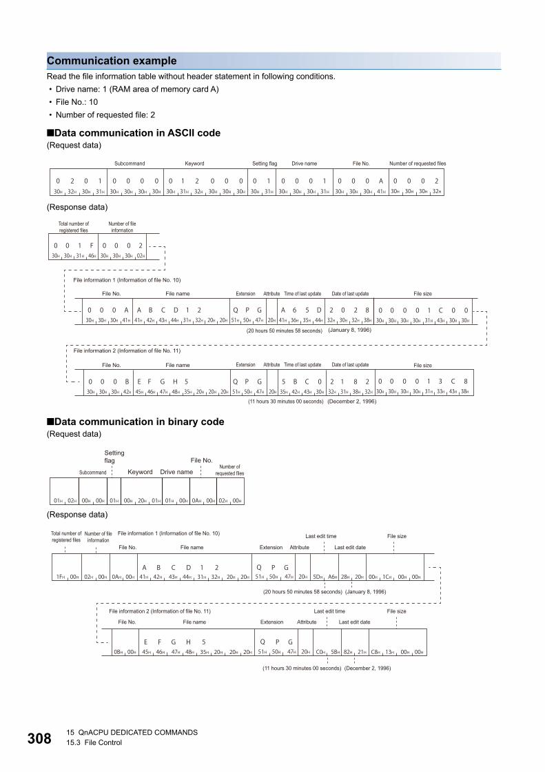
30815 QnACPU DEDICATED COMMANDS15.3 File Control
Communication exampleRead the file information table without header statement in following conditions.
• Drive name: 1 (RAM area of memory card A)
• File No.: 10
• Number of requested file: 2
■Data communication in ASCII code(Request data)
(Response data)
■Data communication in binary code(Request data)
(Response data)
Subcommand Keyword Setting flag Drive name File No. Number of requested files
Total number of registered files
Number of file information
File information 1 (Information of file No. 10)
File No. File name Extension Attribute Time of last update Date of last update File size
(20 hours 50 minutes 58 seconds) (January 8, 1996)
File information 2 (Information of file No. 11)
File sizeFile No. File name Extension Attribute Time of last update Date of last update
(11 hours 30 minutes 00 seconds) (December 2, 1996)
Setting flag File No.
Keyword Drive nameNumber of
requested filesSubcommand
File information 1 (Information of file No. 10)Number of fileinformation
Total number ofregistered files
File sizeLast edit time
File No. File name Extension Attribute Last edit date
(20 hours 50 minutes 58 seconds) (January 8, 1996)
File information 2 (Information of file No. 11) File sizeLast edit time
File name Extension Attribute Last edit dateFile No.
(11 hours 30 minutes 00 seconds) (December 2, 1996)

15 QnACPU DEDICATED COMMANDS15.3 File Control 309
15
Read file information table with header statement (command: 0202)The following examples show the control procedure for reading file information table with header statement within the range of
the specified file No.
Message formatThe following shows the message format of the request data and response data of the command.
■Request data
■Response data
Data specified by request data
■Command
■Subcommand
■KeywordAllow/prohibit the access to the file of the target memory. (Page 296 Keyword)
■Setting flagData that indicates whether the keyword is registered in the specified drive. (Page 296 Setting flag)
■Drive nameA data to specify the drive in a CPU module of which files are to be managed. (Page 296 Drive name, Drive No.)
■File No.A data to specify the registration number of files. (Page 296 File No.)
Specify within the following range.
1 File No. 256
ASCII code Binary code
ASCII code Binary code
ASCII
Subcommand Keyword Setting flag Drive name File No. Number of requested files
Binary
Setting flag
Keyword Drive name File No.Number of requested files
Subcommand
Last edit date
Last edit time
File information(nth point)
File sizeFile name AttributeNumber of file information ExtensionFile No.Total number of
registered filesHeader
statement
File information (first point)
030H
232H
030H
232H 02H 02H
030H
030H
030H
030H 00H 00H

31015 QnACPU DEDICATED COMMANDS15.3 File Control
■Number of requested fileNumber of request files when reading file information. (Page 297 Number of requested file, total number of registered
files, number of file information)
Specify within the following range.
1 Number of requested file 16
Data stored by response data
■Total number of registered filesNumber of files registered in the specified drive. (Page 297 Number of requested file, total number of registered files,
number of file information)
The value is returned within the following range.
1 Total number of registered files 256
■Number of file informationNumber of files that return file information when reading the file information(Page 297 Number of requested file, total
number of registered files, number of file information)
The value is returned within the following range.
0 Number of file information Number of requested file
(0: No registered files after the specified head file No.)
■File No.This indicates the registration number of a file. (Page 296 File No.)
■File nameCharacter string data of a file name. (Page 297 File name, extension, and attribute)
■ExtensionA character string data of extension of a file. (Page 297 File name, extension, and attribute)
■AttributeA data that indicates the file attribute (applicability of data read/write). (Page 297 File name, extension, and attribute)
■Last edit time and last edit dateA data that indicates the date and time when the current data is registered. (Page 298 Last edit time and last edit date)
■File sizeA data that indicates the capacity of the current file in number of bytes. (Page 299 File size)
■Header statementThe header statement attached to the file specified with Engineering tool. (Page 299 Header statement)
• The total number of registered files is the current total number of files registered in the designated drive.
• When all the files are not registered within the specified file number range, the number of file information will
be the number of files registered in the specified range (number of file information to be returned).

15 QnACPU DEDICATED COMMANDS15.3 File Control 311
15
Communication exampleRead the file information table with header statement in following conditions.
• Drive name: 1 (RAM area of memory card A)
• File No.: 10
• Number of requested file: 2
■Data communication in ASCII code(Request data)
(Response data)
■Data communication in binary code(Request data)
(Response data)
Subcommand Keyword Setting flag Drive name File No. Number of requested files
Total number of registered files Number of file information
File information 1 (Information of file No. 10)
File No. File name Extension Attribute Last edit time Last edit date File size
(20 hours 50 minutes 58 seconds) (January 8, 1996)
Header statement (32 characters) File information 2 (Information of file No. 11)
(The order of data items is the same as that of file information 1.)
Setting flag File No.
Keyword Drive nameNumber of
requested filesSubcommand
File information 1 (Information of file No. 10)Number of fileinformation
Total number ofregistered files
File sizeLast edit timeFile No. File name Extension Attribute Last edit date
(20 hours 50 minutes 58 seconds) (January 8, 1996)
Header statement (32 characters) File information 2 (Information of file No. 11)
(The order of data items is the same as that of file information 1.)

31215 QnACPU DEDICATED COMMANDS15.3 File Control
Read file presence (Search file) (command: 0203)The following examples show the control procedure for searching for the specified file, and reading its file No. and file size.
Message format
■Request data
■Response data
If the specified file does not exist, an error occurs and the end code at the occurrence of error is returned.
Data specified by request data
■Command
■Subcommand
■KeywordAllow/prohibit the access to the file of the target memory. (Page 296 Keyword)
■Setting flagData that indicates whether the keyword is registered in the specified drive. (Page 296 Setting flag)
■Drive nameA data to specify the drive in a CPU module of which files are to be managed. (Page 296 Drive name, Drive No.)
■File nameCharacter string data of a file name. (Page 297 File name, extension, and attribute)
■ExtensionA character string data of extension of a file. (Page 297 File name, extension, and attribute)
■AttributeA data to specify the file attribute (applicability of data read/write). (Page 297 File name, extension, and attribute)
Handle the file attribute to be read as dummy data.
ASCII code Binary code
ASCII code Binary code
ASCII
Subcommand Keyword Setting flag Drive name File name Extension Attribute
Binary
Setting flag Keyword Drive name File name Extension AttributeSubcommand
File No. File size
0 2 0 330H 32H 30H 33H 03H 02H
030H
030H
030H
030H 00H 00H

15 QnACPU DEDICATED COMMANDS15.3 File Control 313
15
Data stored by response data
■File No.This indicates the registration number of a file. (Page 296 File No.)
■File sizeThis value indicates the capacity of the current file in number of bytes. (Page 299 File size)
Communication exampleRead the existence of a specified file under the following condition.
• Drive name: 1 (RAM area of memory card A)
• File name: ABC12.QPG
■Data communication in ASCII code(Request data)
(Response data)
■Data communication in binary code(Request data)
(Response data)
Subcommand Keyword Setting flag Drive name File name Extension Attribute
File No. File size
Setting flag
File nameSubcommand Keyword Drive name Extension Attribute
File No. File size
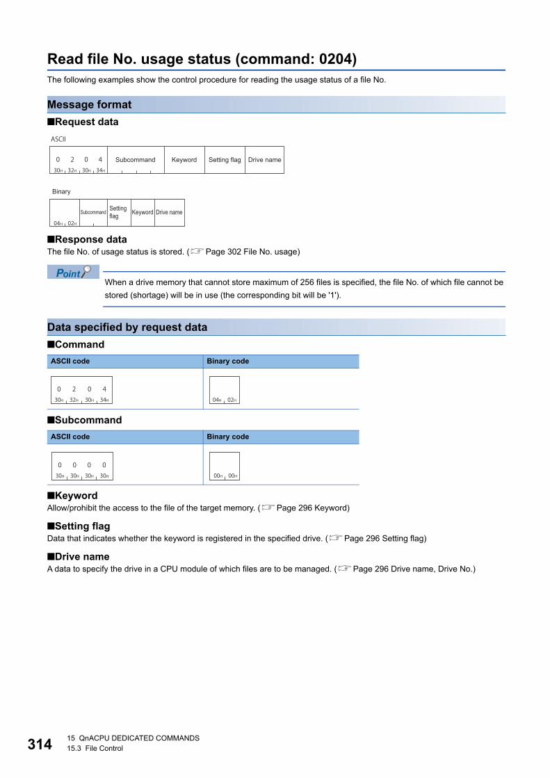
31415 QnACPU DEDICATED COMMANDS15.3 File Control
Read file No. usage status (command: 0204)The following examples show the control procedure for reading the usage status of a file No.
Message format
■Request data
■Response dataThe file No. of usage status is stored. (Page 302 File No. usage)
When a drive memory that cannot store maximum of 256 files is specified, the file No. of which file cannot be
stored (shortage) will be in use (the corresponding bit will be '1').
Data specified by request data
■Command
■Subcommand
■KeywordAllow/prohibit the access to the file of the target memory. (Page 296 Keyword)
■Setting flagData that indicates whether the keyword is registered in the specified drive. (Page 296 Setting flag)
■Drive nameA data to specify the drive in a CPU module of which files are to be managed. (Page 296 Drive name, Drive No.)
ASCII code Binary code
ASCII code Binary code
ASCII
Subcommand Keyword Setting flag Drive name
Binary
Setting flag Keyword Drive nameSubcommand
030H
232H
030H
434H 04H 02H
030H
030H
030H
030H 00H 00H

15 QnACPU DEDICATED COMMANDS15.3 File Control 315
15
Communication exampleRead the file No. usage in the following conditions.
• Drive name: 1 (RAM area of memory card A)
■Data communication in ASCII code(Request data)
(Response data)
■Data communication in binary code(Request data)
(Response data)
Subcommand Keyword Setting flag Drive name
File No. usage status (64 characters)
No.1 to 8 No.9 to No.248 No.249 to 256
Setting flag
Keyword Drive nameSubcommand
File No. usage status (32 bytes)
No.1 to 8 No.9 to No.248 No.249 to 256

31615 QnACPU DEDICATED COMMANDS15.3 File Control
Read file (command: 0206)The following examples show the control procedure for reading the data written in the specified file.
The maximum number of data bytes to be read per one time is fixed. Read all the data written to the specified
file with adjusting the offset address and number of bytes read, and dividing them for several times.
Additionally, save the read data to the external device.
Check the file size with the following function.
Page 306 Read file information table without header statement (command: 0201)
Page 309 Read file information table with header statement (command: 0202)
Page 312 Read file presence (Search file) (command: 0203)
Message format
■Request data
■Response dataThe read data are stored.
Page 300 Read data, write data (for batch read and batch write functions)
ASCII
Subcommand Keyword Setting flag Drive name File No.
File name Extension Attribute Offset address Number of bytes read
Binary
SubcommandSetting flag Keyword Drive name File No.
File name Extension Attribute Offset address
Number of bytes read

15 QnACPU DEDICATED COMMANDS15.3 File Control 317
15
Data specified by request data
■Command
■Subcommand
■KeywordAllow/prohibit the access to the file of the target memory. (Page 296 Keyword)
■Setting flagData that indicates whether the keyword is registered in the specified drive. (Page 296 Setting flag)
■Drive nameA data to specify the drive in a CPU module of which files are to be managed. (Page 296 Drive name, Drive No.)
■File No.A data to specify the registration number of files. (Page 296 File No.)
Specify within the following range.
1 File No. 256
■File nameCharacter string data of a file name. (Page 297 File name, extension, and attribute)
■ExtensionA character string data of extension of a file. (Page 297 File name, extension, and attribute)
■AttributeA data to specify the file attribute (applicability of data read/write). (Page 297 File name, extension, and attribute)
Handle the file attribute to be read as dummy data.
■Offset addressA data to specify the start address of the range from which data is read to a file. (Page 299 Offset address)
Specify within the following range.
0 Address (specify with even address) (File size - 1)
■Number of bytes readA data to specify the number of bytes of the range from which data is read to a file. (Page 300 Number of bytes read,
number of bytes written)
Specify within the following range.
0 Number of bytes 960
ASCII code Binary code
ASCII code Binary code
030H
232H
030H
636H 06H 02H
030H
030H
030H
030H 00H 00H

31815 QnACPU DEDICATED COMMANDS15.3 File Control
Communication exampleRead the data written in the specified file under the following condition.
• Drive name: 1 (RAM area of memory card A)
• File No.: 1
• File name: ABC12.QPG
• Offset address: 100H
• Number of bytes read: 50 bytes
■Data communication in ASCII code(Request data)
(Response data)
■Data communication in binary code(Request data)
(Response data)
Subcommand Keyword Setting flag Drive name File No.
File name Extension Attribute Offset address Number of bytes read
Data read (For 50 bytes)
Address 100H Address 101H to 130H Address 131H
Setting flag File No.
Keyword Drive name File name
Offset addressExtension Attribute Number of bytes read
Subcommand
Data read (For 50 bytes)
Address 101H to 130H
Address 100H Address 131H

15 QnACPU DEDICATED COMMANDS15.3 File Control 319
15
Register and deregister file locks (command: 0808)The following examples show the control procedure for registering and deregistering a file lock.
Restarting QnACPU (such as resetting CPU module) with the file lock registered results in the file lock
deregistered state.
Message format
■Request data
■Response dataThere is no response data for this command.
Data specified by request data
■Command
■Subcommand • Register
• Deregister
■File lock modeA data to specify whether a locked file is to be forcefully unlocked in order to allow other devices to access the specified file.
(Page 302 File lock mode)
■Drive nameA data to specify the drive in a CPU module of which files are to be managed. (Page 296 Drive name, Drive No.)
■File No.A data to specify the registration number of files. (Page 296 File No.)
■File nameCharacter string data of a file name. (Page 297 File name, extension, and attribute)
■ExtensionA character string data of extension of a file. (Page 297 File name, extension, and attribute)
■AttributeA data to specify the file attribute (applicability of data read/write). (Page 297 File name, extension, and attribute)
The attribute assigned by a new file creation, etc. is valid as the attribute of the file that will be locked and unlocked. When
registering and deregistering file lock, handle the file attribute as dummy data.
ASCII code Binary code
ASCII code Binary code
ASCII code Binary code
Subcommand File lock mode Drive name File No. File name Extension AttributeCommand
030H
838H
030H
838H 08H 08H
030H
030H
030H
131H 01H 00H
030H
030H
030H
030H 00H 00H

32015 QnACPU DEDICATED COMMANDS15.3 File Control
Communication example (Register)Read the existence of a specified file under the following condition.
• File lock mode: 0 (usual practice)
• Drive name: 1 (RAM area of memory card A)
• File No.: 1
• File name: ABC12.QPG
■Data communication in ASCII code(Request data)
■Data communication in binary code(Request data)
Subcommand File lock mode Drive name File No.
File name Extension Attribute
File lock mode File No.
File name Extension AttributeDrive nameSubcommand

15 QnACPU DEDICATED COMMANDS15.3 File Control 321
15
Create new file (Register file name) (command: 1202)The following examples show the control procedure for registering a new file and reserving a file area on the specified disk.
Write data to the file created using this function with the following function.
Page 323 Write to file (command: 1203)
The content of file in which data is not written cannot be read.
• A new file can be created on the specified drive memory within the size of consecutive unused clusters.
Creating a new file considering the rest of the capacity for future use is recommended.
• The QnACPU management time is registered as the last edit date and time to a new file created using this
function.
Message format
■Request data
■Response dataFile No. is stored. (Page 296 File No.)
Data specified by request data
■Command
■Subcommand
■KeywordAllow/prohibit the access to the file of the target memory. (Page 296 Keyword)
■Setting flagData that indicates whether the keyword is registered in the specified drive. (Page 296 Setting flag)
ASCII code Binary code
ASCII code Binary code
ASCII
Subcommand Keyword Setting flag Drive name Fixed value Fixed value
File name Extension Attribute Size Fixed value
Binary
Subcommand Setting flag
Keyword Drive name Fixed value Fixed value
File name Extension Attribute Size Fixed value
131H
232H
030H
232H 02H 12H
030H
030H
030H
030H 00H 00H
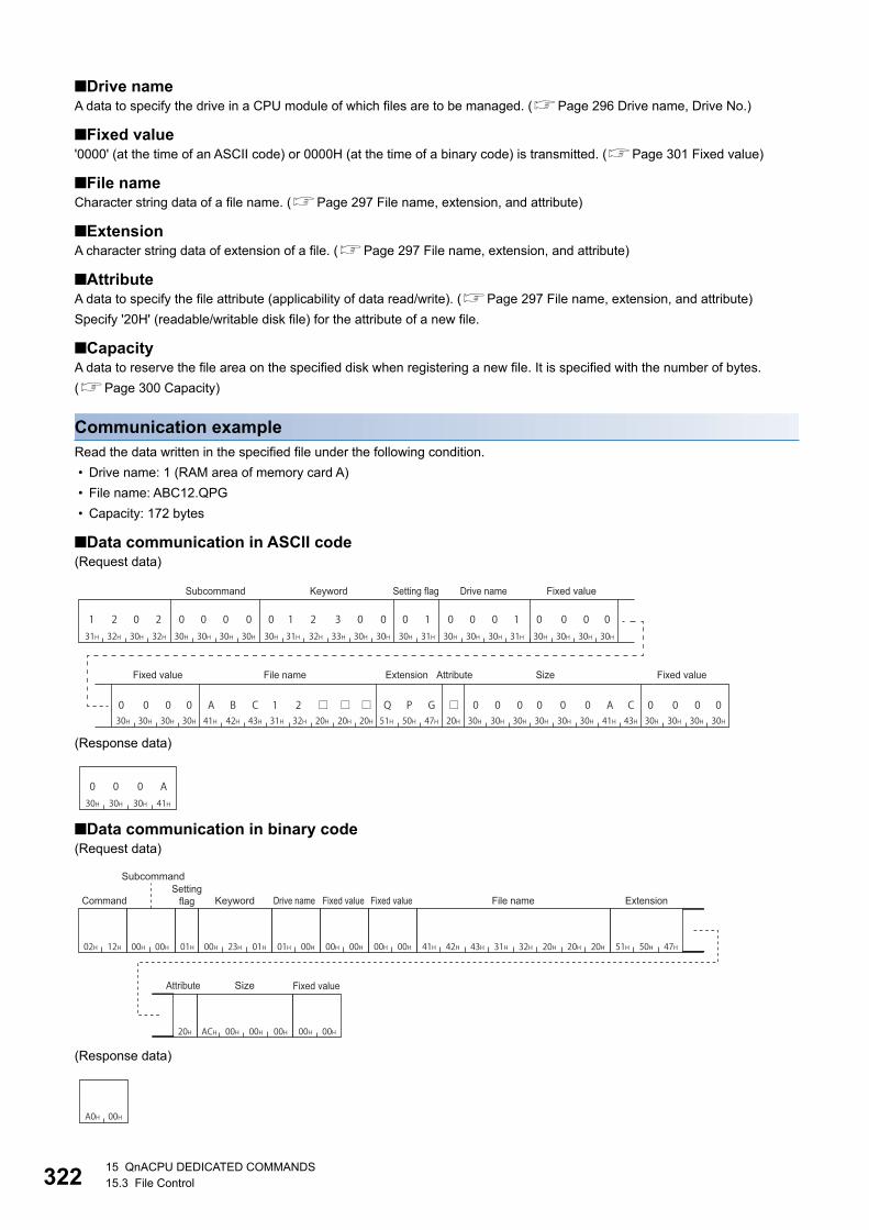
32215 QnACPU DEDICATED COMMANDS15.3 File Control
■Drive nameA data to specify the drive in a CPU module of which files are to be managed. (Page 296 Drive name, Drive No.)
■Fixed value'0000' (at the time of an ASCII code) or 0000H (at the time of a binary code) is transmitted. (Page 301 Fixed value)
■File nameCharacter string data of a file name. (Page 297 File name, extension, and attribute)
■ExtensionA character string data of extension of a file. (Page 297 File name, extension, and attribute)
■AttributeA data to specify the file attribute (applicability of data read/write). (Page 297 File name, extension, and attribute)
Specify '20H' (readable/writable disk file) for the attribute of a new file.
■CapacityA data to reserve the file area on the specified disk when registering a new file. It is specified with the number of bytes.
(Page 300 Capacity)
Communication exampleRead the data written in the specified file under the following condition.
• Drive name: 1 (RAM area of memory card A)
• File name: ABC12.QPG
• Capacity: 172 bytes
■Data communication in ASCII code(Request data)
(Response data)
■Data communication in binary code(Request data)
(Response data)
Fixed valueSubcommand Keyword Setting flag Drive name
Fixed value Fixed valueFile name Extension Attribute Size
030H
030H
030H
A41H
02H 12H 00H 00H 01H 00H 23H 01H 01H 00H
ACH
00H 00H 00H 00H 41H 42H 43H 31H 32H 20H 20H 20H 51H 50H 47H
20H 00H 00H 00H 00H 00H
SubcommandSetting
flagCommand Keyword Drive name Fixed value Fixed value File name Extension
Attribute Size Fixed value
A0H 00H
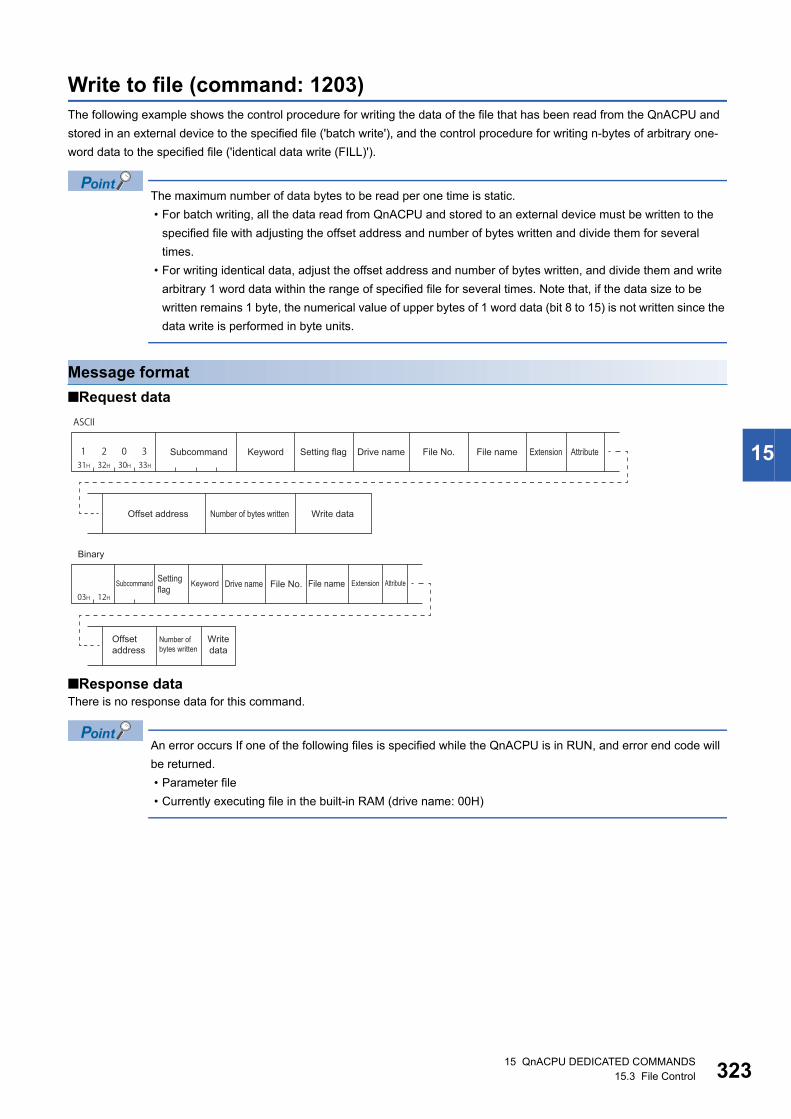
15 QnACPU DEDICATED COMMANDS15.3 File Control 323
15
Write to file (command: 1203)The following example shows the control procedure for writing the data of the file that has been read from the QnACPU and
stored in an external device to the specified file ('batch write'), and the control procedure for writing n-bytes of arbitrary one-
word data to the specified file ('identical data write (FILL)').
The maximum number of data bytes to be read per one time is static.
• For batch writing, all the data read from QnACPU and stored to an external device must be written to the
specified file with adjusting the offset address and number of bytes written and divide them for several
times.
• For writing identical data, adjust the offset address and number of bytes written, and divide them and write
arbitrary 1 word data within the range of specified file for several times. Note that, if the data size to be
written remains 1 byte, the numerical value of upper bytes of 1 word data (bit 8 to 15) is not written since the
data write is performed in byte units.
Message format
■Request data
■Response dataThere is no response data for this command.
An error occurs If one of the following files is specified while the QnACPU is in RUN, and error end code will
be returned.
• Parameter file
• Currently executing file in the built-in RAM (drive name: 00H)
ASCII
Subcommand Keyword Setting flag Drive name File No. File name Extension Attribute
Offset address Number of bytes written Write data
Binary
Setting flag
Keyword Drive name File No. File name Extension Attribute
Offset address
Number of bytes written
Write data
Subcommand

32415 QnACPU DEDICATED COMMANDS15.3 File Control
Data specified by request data
■Command
■Subcommand
■KeywordAllow/prohibit the access to the file of the target memory. (Page 296 Keyword)
■Setting flagData that indicates whether the keyword is registered in the specified drive. (Page 296 Setting flag)
■Drive nameA data to specify the drive in a CPU module of which files are to be managed. (Page 296 Drive name, Drive No.)
■File No.A data to specify the registration number of files. (Page 296 File No.)
■File nameCharacter string data of a file name. (Page 297 File name, extension, and attribute)
■ExtensionA character string data of extension of a file. (Page 297 File name, extension, and attribute)
■AttributeA data to specify the file attribute (applicability of data read/write). (Page 297 File name, extension, and attribute)
The attribute assigned by a new file creation, etc. is valid as the attribute of the file to which data is written. When writing data,
handle the attribute as dummy data.
■Offset addressA data which specifies the start address of the range in which data is written to a file. (Page 299 Offset address)
Specify within the following range.
0 Address (File size - 1)
• Writing data to file of which drive name is '00H' (built-in RAM): Specify with multiples of 4 (0, 4, 8, ... in decimal notation).
• Writing to the file of which drive name is other than '00H': Specify with even number (for decimal data, 0, 2, 4, 6, 8, ...).
■Number of bytes writtenData to specify the number of bytes of data to be written. (Page 300 Number of bytes read, number of bytes written)
Specify within the following range.
0 Number of bytes 960
■Write dataData to be written to a file. (Page 300 Read data, write data (for batch read and batch write functions))
ASCII code Binary code
Type ASCII code Binary code
Batch write
Writing the identical data (FILL)
131H
232H
030H
333H 03H 12H
030H
030H
030H
030H 00H 00H
030H
030H
030H
131H 01H 00H

15 QnACPU DEDICATED COMMANDS15.3 File Control 325
15
Communication example (Batch write)Batch write is executed under the following condition.
• Drive name: 1 (RAM area of memory card A)
• File No.: 1
• File name: ABC12.QPG
• Offset address: 7CH
• Number of bytes written: 416 bytes
■Data communication in ASCII code(Request data)
■Data communication in binary code(Request data)
Subcommand Keyword Setting flag Drive name File No.
File name Extension Attribute Offset address Number of bytes written
Address 7CH Address 7DH to 21AH Address 21BH
Write data (For 416 bytes)
Setting flag File No.
Keyword Drive name File name
Number of bytes written Address 7DH to 21AH
Extension Attribute Offset address Address 7CH Address 21BH
Write data (For 416 bytes)
Subcommand
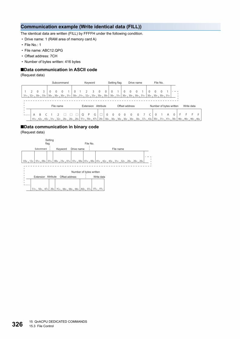
32615 QnACPU DEDICATED COMMANDS15.3 File Control
Communication example (Write identical data (FILL))The identical data are written (FILL) by FFFFH under the following condition.
• Drive name: 1 (RAM area of memory card A)
• File No.: 1
• File name: ABC12.QPG
• Offset address: 7CH
• Number of bytes written: 416 bytes
■Data communication in ASCII code(Request data)
■Data communication in binary code(Request data)
Subcommand Keyword Setting flag Drive name File No.
File name Extension Attribute Offset address Number of bytes written Write data
Setting flag File No.
Keyword Drive name File name
Number of bytes written
Extension Attribute Offset address Write data
Subcommand
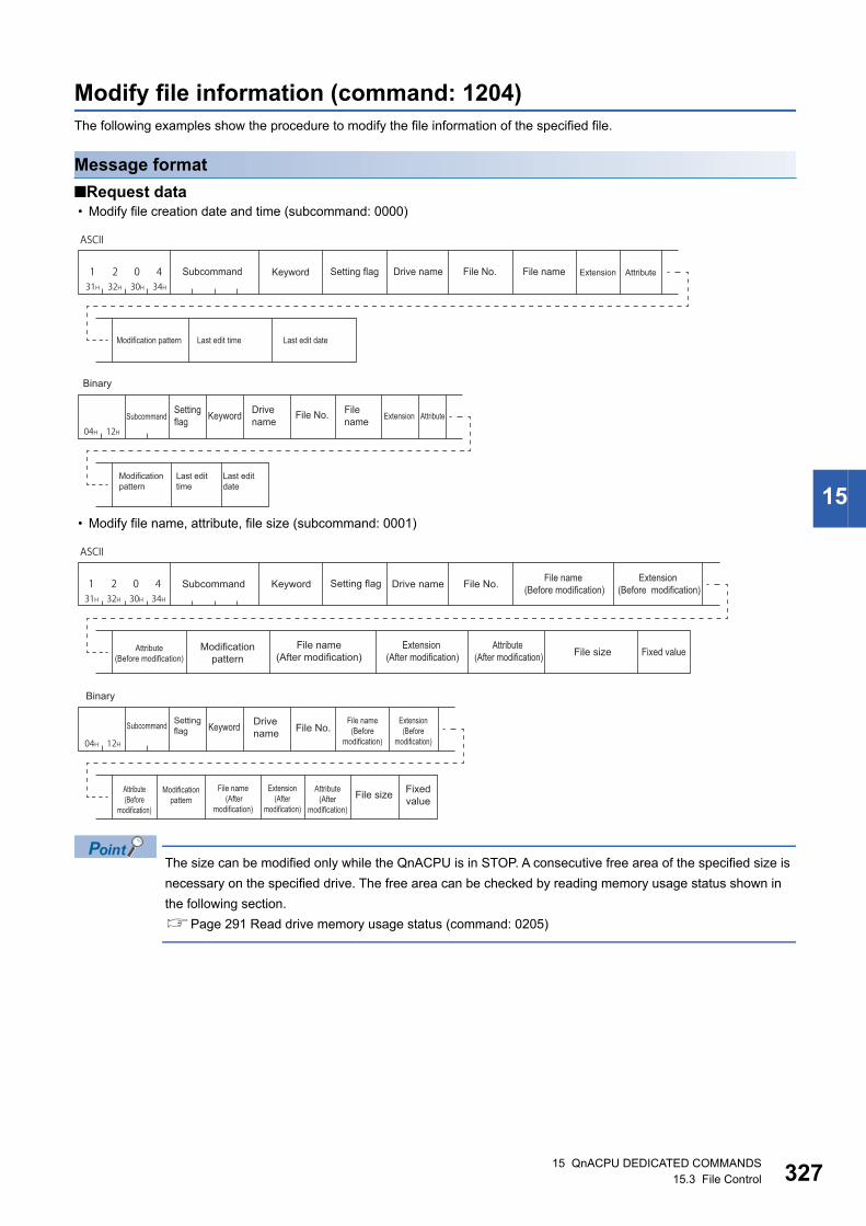
15 QnACPU DEDICATED COMMANDS15.3 File Control 327
15
Modify file information (command: 1204)The following examples show the procedure to modify the file information of the specified file.
Message format
■Request data • Modify file creation date and time (subcommand: 0000)
• Modify file name, attribute, file size (subcommand: 0001)
The size can be modified only while the QnACPU is in STOP. A consecutive free area of the specified size is
necessary on the specified drive. The free area can be checked by reading memory usage status shown in
the following section.
Page 291 Read drive memory usage status (command: 0205)
ASCII
Subcommand Keyword Setting flag Drive name File No. File name Extension Attribute
Modification pattern Last edit time Last edit date
Binary
Setting flag Keyword Drive
nameFile No. File
name Extension Attribute
Modification pattern
Last edit time
Last editdate
Subcommand
ASCII
Subcommand Keyword Setting flag Drive name File No. File name (Before modification)
Extension (Before modification)
Attribute (Before modification)
Modification pattern
File name (After modification)
Extension (After modification)
Attribute (After modification) File size Fixed value
Binary
Setting flag Keyword Drive
name File No.File name(Before
modification)
Extension(Before
modification)
Attribute(Before
modification)
Modification pattern
File name (After
modification)
Extension(After
modification)
Attribute(After
modification)File size Fixed
value
Subcommand
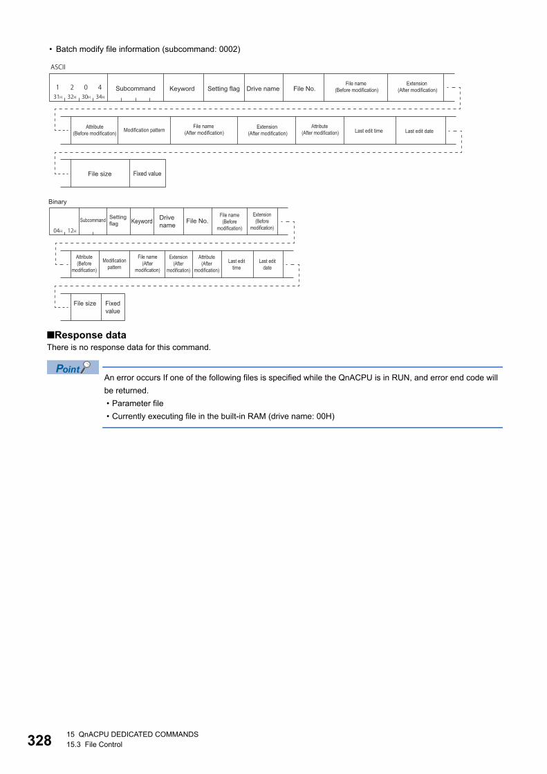
32815 QnACPU DEDICATED COMMANDS15.3 File Control
• Batch modify file information (subcommand: 0002)
■Response dataThere is no response data for this command.
An error occurs If one of the following files is specified while the QnACPU is in RUN, and error end code will
be returned.
• Parameter file
• Currently executing file in the built-in RAM (drive name: 00H)
ASCII
Subcommand Keyword Setting flag Drive name File No.File name
(Before modification)Extension
(After modification)
Attribute (Before modification) Modification pattern
File name (After modification)
Extension (After modification)
Attribute (After modification) Last edit time Last edit date
File size Fixed value
Binary
Setting flag Keyword Drive
nameFile No.
File name(Before
modification)
Extension(Before
modification)
Attribute(Before
modification)
Modification pattern
File name (After
modification)
Extension(After
modification)
Attribute(After
modification)Last edit
timeLast edit
date
File size Fixed value
Subcommand
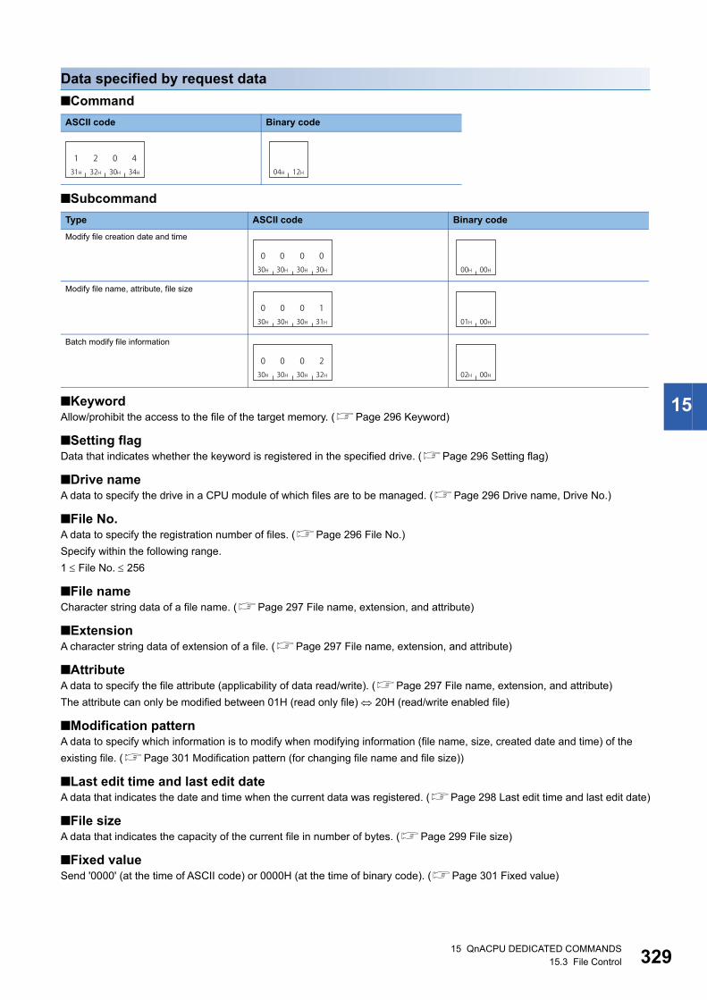
15 QnACPU DEDICATED COMMANDS15.3 File Control 329
15
Data specified by request data
■Command
■Subcommand
■KeywordAllow/prohibit the access to the file of the target memory. (Page 296 Keyword)
■Setting flagData that indicates whether the keyword is registered in the specified drive. (Page 296 Setting flag)
■Drive nameA data to specify the drive in a CPU module of which files are to be managed. (Page 296 Drive name, Drive No.)
■File No.A data to specify the registration number of files. (Page 296 File No.)
Specify within the following range.
1 File No. 256
■File nameCharacter string data of a file name. (Page 297 File name, extension, and attribute)
■ExtensionA character string data of extension of a file. (Page 297 File name, extension, and attribute)
■AttributeA data to specify the file attribute (applicability of data read/write). (Page 297 File name, extension, and attribute)
The attribute can only be modified between 01H (read only file) 20H (read/write enabled file)
■Modification patternA data to specify which information is to modify when modifying information (file name, size, created date and time) of the
existing file. (Page 301 Modification pattern (for changing file name and file size))
■Last edit time and last edit dateA data that indicates the date and time when the current data was registered. (Page 298 Last edit time and last edit date)
■File sizeA data that indicates the capacity of the current file in number of bytes. (Page 299 File size)
■Fixed valueSend '0000' (at the time of ASCII code) or 0000H (at the time of binary code). (Page 301 Fixed value)
ASCII code Binary code
Type ASCII code Binary code
Modify file creation date and time
Modify file name, attribute, file size
Batch modify file information
131H
232H
030H
434H 04H 12H
030H
030H
030H
030H 00H 00H
030H
030H
030H
131H 01H 00H
030H
030H
030H
232H 02H 00H

33015 QnACPU DEDICATED COMMANDS15.3 File Control
Communication example (Modify file creation time) (subcommand: 0000)Modify the creation time of the following file.
• Drive name: 1 (RAM area of memory card A)
• File name: ABC12.QPG
• Modification pattern: 14H (specify the time of QnACPU for the last edit time.)
■Data communication in ASCII code(Request data)
■Data communication in binary code(Request data)
Subcommand Keyword Setting flag Drive name File No.
File name Extension Attribute Modification pattern Last edit time Last edit date
Setting flag File No.
Keyword Drive name
Modification pattern Last edit date
Last edit timeExtension AttributeFile name
Subcommand

15 QnACPU DEDICATED COMMANDS15.3 File Control 331
15
Communication example (Modify file name, attribute) (subcommand: 0001)Modify the file name and attribute of the following file.
• Drive name: 1 (RAM area of memory card A)
• File No.: 1
• File name (before modification): ABC12.QPG
• File name (after modification): ABC1234.QPG
• Attribute (before modification): 20H (disk files that can be read/written)
• Attribute (after modification): 01H (read only file)
■Data communication in ASCII code(Request data)
■Data communication in binary code(Request data)
Subcommand Keyword Setting flag Drive name File No.
Attribute (Before modification)
File name (Before modification) Extension (Before modification) Modification pattern File name (After modification)
Attribute (After modification)
Extension (After modification) File size Fixed value
Setting flag File No.
Keyword Drive name
Extension (Before modification) Modification patternAttribute
(Before modification)File name (Before modification) File name (After modification)
Extension (After modification) File sizeAttribute
(After modification) Fixed value
Subcommand

33215 QnACPU DEDICATED COMMANDS15.3 File Control
Communication example (Batch modify file information) (subcommand: 0002)Modify the file name of the following files, attribute, and last edit date and time.
• Drive name: 1 (RAM area of memory card A)
• File No.: 1
• File name (before modification): ABC12.QPG
• File name (after modification): ABC1234.QPG
• Attribute (before modification): 20H (disk files that can be read/written)
• Attribute (after modification): 01H (read only file)
• Modification pattern: 1FH (Specify the date and time of QnACPU to the last edit day and last edit time)
■Data communication in ASCII code(Request data)
■Data communication in binary code(Request data)
Subcommand Keyword Setting flag Drive name File No.
Attribute (Before modification)
File name (Before modification)
Extension (Before modification) Modification pattern File name (After modification)
Attribute (After modification)
Extension (After modification) File size Fixed valueLast edit time Last edit date
Setting flag File No.
Keyword Drive name
Extension (Before modification) Modification patternAttribute
(Before modification)File name (Before modification) File name (After modification)
Extension (After modification) Last edit time File sizeAttribute
(After modification) Fixed valueLast edit date
Subcommand

15 QnACPU DEDICATED COMMANDS15.3 File Control 333
15
Delete file (command: 1205)The following examples show the procedure to delete the existing files.
Determine the file deletion timing for the entire system, including the QnACPU and related devices.
The file in which the file lock has been registered cannot be deleted.
When QnACPU is in RUN, the following files cannot be deleted.
• Program file (.QPG)
• Parameter file (.QPA)
• Boot setting file (.QBT)
Message format
■Request data
■Response dataThere is no response data for this command.
Data specified by request data
■Command
■Subcommand
■KeywordAllow/prohibit the access to the file of the target memory. (Page 296 Keyword)
■Setting flagData that indicates whether the keyword is registered in the specified drive. (Page 296 Setting flag)
■Drive nameA data to specify the drive in a CPU module of which files are to be managed. (Page 296 Drive name, Drive No.)
■File No.A data to specify the registration number of files. (Page 296 File No.)
■File nameCharacter string data of a file name. (Page 297 File name, extension, and attribute)
ASCII code Binary code
ASCII code Binary code
ASCII
Subcommand Keyword Setting flag Drive name File No. File name Extension Attribute
Binary
Setting flag Keyword Drive
name File No. File name Extension AttributeSubcommand
131H
232H
030H
535H 05H 12H
30H 30H 30H 30H
0 0 0 000H 00H

33415 QnACPU DEDICATED COMMANDS15.3 File Control
■ExtensionA character string data of extension of a file. (Page 297 File name, extension, and attribute)
■AttributeA data to specify the file attribute (applicability of data read/write). (Page 297 File name, extension, and attribute)
When deleting a file, handle the attribute as dummy data.
Communication exampleDelete files under the following conditions.
• Drive name: 1 (RAM area of memory card A)
• File No.: 1
• File name: ABC12.QPG
■Data communication in ASCII code(Request data)
■Data communication in binary code(Request data)
Subcommand Keyword Setting flag Drive name File No.
File name Extension Attribute
Setting flag File No.
Keyword Drive name
Extension AttributeFile name
Subcommand

15 QnACPU DEDICATED COMMANDS15.3 File Control 335
15
Copy file (command: 1206)The following examples show the procedure to copy a file. (For QnACPU)
The maximum number of data bytes to be copies per one time is static. For the data which are already written, adjust the
offset address and number of copy bytes, and divide them and write to the new registration file for several times.
Message format
■Request data
■Response dataThere is no response data for this command.
An error occurs If one of the following files is specified while the QnACPU is in RUN, and error end code will
be returned.
• Parameter file
• Currently executing file in the built-in RAM (drive name: 00H)
Subcommand
ASCII
Number of bytes
readCopy mode
Copy source
Offset addressFile No.Setting flagKeyword Drive name File name Extension Attribute
Copy destination
Offset addressFile No.Setting flagKeyword Drive name File name Extension Attribute
Number of bytes
read
Copy mode
Copy source
Offset addressFile No.Setting
flag Keyword Drive name
File name Extension Attribute
Copy destination
Subcommand
Offset addressFile No.Setting
flag Keyword Drive name
File name Extension Attribute

33615 QnACPU DEDICATED COMMANDS15.3 File Control
Data specified by request data
■Command
■Subcommand
■KeywordAllow/prohibit the access to the file of the target memory. (Page 296 Keyword)
■Setting flagThis indicates whether the keyword registered in the specified drive matches the keyword of request data. (Page 288
Setting flag)
■Drive nameA data to specify the drive in a CPU module of which files are to be managed. (Page 296 Drive name, Drive No.)
■File No.A data to specify the registration number of files. (Page 296 File No.)
■File nameCharacter string data of a file name. (Page 297 File name, extension, and attribute)
■ExtensionA character string data of extension of a file. (Page 297 File name, extension, and attribute)
■AttributeA data to specify the file attribute (applicability of data read/write). (Page 297 File name, extension, and attribute)
The attribute assigned by a new file creation, etc. is valid as the attribute of the source and destination files. When copying a
file, handle the attribute as dummy data.
■Offset addressA data to specify the start address of the range from which data is read to a file. (Page 299 Offset address)
Specify within the following range.
Offset address: 0 Address (File size - 1)
• Copy to the file whose drive name is '00H' (Built-in RAM): Specify with multiples of 4 (0, 4, 8, ... in decimal notation).
• Copy to the file whose drive name is other than '00H': Specify with even number (for decimal data, 0, 2, 4, 6, 8, ...).
■Number of bytes read (number of copy bytes)A data to specify the range from which data is read in byte unit to file. Specify the data as one address per one byte.
(Page 300 Number of bytes read, number of bytes written)
Specify within the following range.
Number of copied bytes: 0 Number of bytes 480
■Copy modeA data to specify whether to copy the last edit time and data of the source file to the target file at the completion of copying.
When the time and date are not copied, the QnACPU management time at a new file creation will remain. (Page 303
Copy mode)
ASCII code Binary code
ASCII code Binary code
131H
232H
030H
636H 06H 12H
030H
030H
030H
030H 00H 00H

15 QnACPU DEDICATED COMMANDS15.3 File Control 337
15
Communication exampleCopy the file with the following condition.
• Drive name (copy source): 1 (RAM area of memory card A)
• Drive name (copy destination): 3 (RAM area of memory card B)
• File No. (copy source): 1H (1)
• File No. (copy destination): AH (10)
• File name (copy source): ABC12.QPG
• File name (copy destination): ABC12001.QPG
• Offset address (copy source): 1E0H
• Number of bytes read (copy source): 480 bytes
• Copy mode (copy source): 0 (Do not copy the last edit date and time of the copy source.)
■Data communication in ASCII code(Request data)
Subcommand Keyword Setting flag Drive name File No.
Copy source
File name Extension Attribute Offset address Number of bytes read Copy mode
Copy source
Keyword Setting flag Drive name File No. File name
Copy destination
Extension Attribute Offset address
Copy destination

33815 QnACPU DEDICATED COMMANDS15.3 File Control
■Data communication in binary code(Request data)
Setting flag File No.
Keyword Drive name File name
Copy source
Offset address
Copy mode
Setting flag
Extension Attribute Number of bytes read Keyword Drive name
Copy source Copy destination
Offset address
Extension AttributeFile nameFile No.
Copy destination
Subcommand

339
PA
RT
5
PART 5 COMPATIBILITY WITH A SERIES
This part explains the specifications when using MELSEC-A series devices.
16 MELSEC-A SERIES SUPPORTED SPECIFICATIONS
17 COMMUNICATING USING 1C FRAMES
18 COMMUNICATING USING 1E FRAMES

34016 MELSEC-A SERIES SUPPORTED SPECIFICATIONS16.1 Frames and Commands that can be Used
16 MELSEC-A SERIES SUPPORTED SPECIFICATIONS
This chapter explains the specifications of the messages of MC protocol and access ranges when using the MELSEC-A
series devices as follows:
• When accessing system including MELSEC-A series modules
• When utilizing the software for data communication created for MELSEC-A series programmable controller.
16.1 Frames and Commands that can be UsedWhen accessing MELSEC-A series modules, all frames of MC protocol can be used.
However, the commands that can be used have some restrictions. (Page 469 Accessible Modules for Each Command)
A compatible frameThe following frames have compatibility with the message protocol and the message format for MELSEC-A series.
16.2 Accessible modulesThe following MELSEC-A series modules can be accessed within the access range.
Accessible modules to other stationsThe following modules can be accessed.
Modules that can be relayed between networksFor the modules that can be relayed between networks when accessing MELSEC-A series module, refer to the following
table.
■MELSEC-A series module
■Module other than MELSEC-A seriesPage 284 Modules that can be relayed between networks
Frame Compatible message format Accessible range
1C frame Dedicated protocols for MELSEC-A series computer link modules Page 47 Accessible range of 1C frame
1E frame Message formats for MELSEC-A series Ethernet interface modules Page 49 Accessible range of 1E frame
Type Model name
CPU module A1NCPU, A2NCPU, A2NCPU-S1, A3NCPU, A2ACPU, A2ACPU-S1, A3ACPU, A2UCPU, A2UCPU-S1, A3UCPU, A4UCPU
A1SCPU, A1SJCPU(-S3), A1SHCPU, A1SJHCPU, A2SCPU, A2SHCPU, A2USCPU, A2USCPU-S1, A2USHCPU-S1
A0J2HCPU
Q02CPU-A, Q02HCPU-A, Q06HCPU-A
A2CCPUC24 and A2CCPUC24-PRF (when connected to an external device by multidrop connection.)
MELSECNET/10 remote I/O AJ72LP25 (G), AJ72BR15
Special function module Refer to the following section.
Page 383 Accessible modules
Network Model name
MELSECNET/10 AJ71LP21 (G), AJ71BR11, A1SJ71LP21, A1SJ71BR11

16 MELSEC-A SERIES SUPPORTED SPECIFICATIONS16.3 Considerations 341
16
16.3 ConsiderationsThe following shows the considerations when using MELSEC-A series devices.
Considerations when connecting C24
■When a computer link module is included in multidrop connectionAccess in ASCII code (format 1 to format 4). A binary code (format 5) cannot be used. (Including the access to the connected
station)
Considerations when connecting E71
■Setting range of monitoring timerWhen accessing ACPU for the first time, the wait time for CPU monitoring timer is required before receiving a response
message because QnACPU identifies the CPU type. Be sure to set a value within the setting range shown below.
Access target Monitoring timer
Connected station (host station) 1H to 28H (0.25 s to 10 s)
Other station 2H to F0H (0.5 s to 60 s)

34217 COMMUNICATING USING 1C FRAMES17.1 Message Format
17 COMMUNICATING USING 1C FRAMES
This chapter explains the functions when accessing using 1C frame and their message format.
1C frame is compatible with the communication function of the dedicated protocols supported by A series computer link
modules.
Only the commands for 1C frame explained in this chapter can be used for 1C frame.
17.1 Message FormatThis section explains the message format when communicating data using 1C frame.
Message format
■Request message
■Response message (Normal completion: Response data)
■Response message (Normal completion: No response data)
■Response message (Abnormal completion)
Setting dataSet the following items.
Item Description Reference
Data by format The message formats differ depending on the set format (Format 1 to
Format 4).
Page 29 Message Formats of Each Protocol
Access route Station No. Specify the station to be connected from an external device. Page 50 Station No.
PC No. Specify the network module station No. of an access target. Page 52 Network No., PC No.
Data by the format Access route Request data Data by the format
Station No.
Character area
Command Message wait
PC No.
Data by the format Access route Data by the format Response data Data by the format
Station No.
PC No. Character area
Data by the format Access route Data by the format
Station No.
PC No.
Access routeData by the format Data by the format
PC No.Station No.
Error code

17 COMMUNICATING USING 1C FRAMES17.1 Message Format 343
17Request data Command Specify the function to request such as read or write. Page 344 Command
Message wait A data to generate a delay time for response transmission.
Specify the wait time within the range of 0 to 150 ms in 10 ms units.
Page 345 Message wait
Character
area
A data that instructs the CPU module to execute a request specified by
command. The content of the character areas differs depending on the
command.
Page 345 Character area
Response
data
Character
area
A data that C24 returns to a request specified by a command. The content
of the character areas differs depending on the command.
Error code Error code indicates the content of occurred error. Page 346 Error code
Item Description Reference

34417 COMMUNICATING USING 1C FRAMES17.2 Details of Setting Data
17.2 Details of Setting DataThis section explains how to specify the common data items and their content in each message.
CommandSet the command type. (Page 347 Command and Function Lists for 1C Frame)
The setting values for each command are as follows.
Setting methodUse the commands by converting to 2-digit (hexadecimal) ASCII codes.
Ex.
Device memory batch read (BR) in bit unit
Function ACPU common command
AnA/AnUCPU common command
Reference
Symbol ASCII code Symbol ASCII code
Device memory read and
write
BR 42H, 52H JR 4AH, 52H Page 352 Batch read (bit units) (command: BR, JR)
WR 57H, 52H QR 51H, 52H Page 354 Batch read (word units) (command: WR, QR)
BW 42H, 57H JW 4AH, 57H Page 356 Batch write (bit units) (command: BW, JW)
WW 57H, 57H QW 51H, 57H Page 358 Batch write (word units) (command: WW, QW)
BT 42H, 54H JT 4AH, 54H Page 360 Test (random write) (bit units) (command: BT, JT)
WT 57H, 54H QT 51H, 54H Page 362 Test (random write) (word units) (command: WT, QT)
BM 42H, 4DH JM 4AH, 4DH Page 365 Register monitor data (bit units) (command: BM, JM)
WM 57H, 4DH QM 51H, 4DH Page 366 Register monitor data (word units) (command: WM, QM)
MB 4DH, 42H MJ 4DH, 4AH Page 367 Monitor (bit units) (command: MB, MJ)
MN 4DH, 4EH MQ 4DH, 51H Page 368 Monitor (word units) (command: MN, MQ)
Read and write extended
file register
ER 45H. 52H Page 373 Batch read (command: ER)
EW 45H, 57H Page 374 Batch write (command: EW)
NR 4EH, 52H Page 379 Direct read (command: NR)
NW 4EH, 57H Page 380 Direct write (command: NW)
ET 45H, 54H Page 375 Test (random write) (command: ET)
EM 45H, 4DH Page 377 Register monitor data (command: EM)
ME 4DH, 45H Page 378 Monitor (command: ME)
Read/write buffer memory
of special function module
TR 54H, 52H Page 384 Batch read (command: TR)
TW 54H, 57H Page 386 Batch write (command: TW)
Loopback test TT 54H, 54H Page 387 Loopback test (Command: TT)
B R42H 52H

17 COMMUNICATING USING 1C FRAMES17.2 Details of Setting Data 345
17Message waitMessage wait is a data to generate a delay time for response transmission.
Some external devices may take time to become receiving status after sending a command.
Specify the minimum wait time to send the result after C24 is received a command from an external device. Specify the wait
time in accordance with the specifications of the external device.
Setting methodSpecify the wait time within the range of 0 to 150 ms in 10 ms units.
Convert 0H to FH (0 to 15) to 1-digit (hexadecimal) ASCII codes regarding 10 ms as 1H.
Ex.
When the message wait time is 100 ms
If the following value is set to message wait in request message, after passing 100 ms or more, transmission of a response
message will be started.
Character areaThe content of the character areas differs depending on the command.
The character area of request data is equivalent to the character A area and the character C area of the dedicated protocols
for A series computer link module. The character are of response data is equivalent to the character B area of a dedicated
protocols.
• Character area A: A data that C24 instructs the CPU module to perform the read request specified by command.
• Character area B: A data that C24 returns to a request specified by a command.
• Character area C: A data that C24 instructs the CPU module to perform the write request specified by command.
When reading data (Response data)The following shows the image when the response data (character B area of the dedicated protocol) is included in the
response message.
(The head of the message data in the figure is a control code of format 1. Page 29 Message Formats of Each Protocol)
A41H
Q25HCPU
MODERUNERR.
USERBAT.
BOOT
RS-232
USB
MITSUBISHI
MELSECPOWER
PULL
QJ71E71RUN
INIT.OPEN
SD
ERR.COM.ERR
RD
10BASE-T
+12V
12G
10BASE
QJ71C24
CH1. CH2.
RS-232
CH1.
CH.2
SDA
SG
SDB
RS-422 /485
RDA
RDB
(FG)
(FG)
1
2
5
7
3
4
6
MODESD
RUN
ERR.
PRMD LINKRD
ST
NO
x10 0 1 0 1
IN
O U T
External deviceResponse message that can be abbreviated
(Normal completion)Command Message wait
Character area ARequest message
Character area B
Response messageTransmission orderSupported devices(Normal completion : The response data exist.) or Error code
Response message (Abnormal completion)
ACK
STX
NAK
ENQ

34617 COMMUNICATING USING 1C FRAMES17.2 Details of Setting Data
When writing data (No response data) The following shows the image when the response data is not included in the response message.
(The head of the message data in the figure is a control code of format 1. Page 29 Message Formats of Each Protocol)
Error codeError code indicates the content of occurred error.
If more than one error occurs at the same time, the error code detected first is returned.
For the content of error code and its corrective action, refer to the user's manual of the module used.
MELSEC iQ-R Serial Communication Module User's Manual(Application)
Q Corresponding Serial Communication Module User's Manual (Basic)
MELSEC-L Serial Communication Module User's Manual (Basic)
Setting methodConvert the numerical value to 2-digit ASCII code (hexadecimal), and send it from the upper digits.
Ex.
For error code 05H
ENQ
NAK
ACKQ25HCPU
MODERUNERR.
USERBAT.
BOOT
RS-232
USB
MITSUBISHI
MELSECPOWER
PULL
QJ71E71RUN
INIT.OPEN
SD
ERR.COM.ERR
RD
10BASE-T
+12V
12G
10BASE
QJ71C24
CH1. CH2.
RS-232
CH1.
CH.2
SDA
SG
SDB
RS-422 /485
RDA
RDB
(FG)
(FG)
1
2
5
7
3
4
6
MODESD
RUN
ERR.
PRMD LINKRD
ST
NO
x10 0 1 0 1
IN
O U T
External device
Message waitCommand
Character area CRequest message
Response messageTransmission orderSupported devices (Normal completion : The
response data does not exist.) Error code
Response message (Abnormal completion)
or
0 530H 35H

17 COMMUNICATING USING 1C FRAMES17.3 Command and Function Lists for 1C Frame 347
1717.3 Command and Function Lists for 1C FrameUse the following commands for data communication using 1C frame.
*1 Use the dedicated commands for extended registers to read/write extended file registers from/to ACPU.*2 The devices for the five types of commands (BM, JM, WM, QM, EM) for registering monitor data can be registered simultaneously in
C24 for each interface.
ACPU common command, AnA/AnUCPU common commandACPU common command is a communication function issued by MC protocol. The command is accessible for ACPU.
AnA/AnUCPU common command is a command for AnACPU and AnUCPU. The command cannot be executed for other
than AnA/AnUCPU.
: Executable, : Executable (with restrictions), : Not executable
When accessing modules other than ACPU, there is a restriction for the accessible device range.
Page 348 Considerations when accessing devices other than ACPU module
Function ACPU common command
AnA/AnUCPU common command
Description
Device memory*1
Batch read Bit units BR JR Reads bit devices (X, Y, M, etc.) in 1-point units.
Word units WR QR Reads bit devices (X, Y, M, etc.) in 16-point units.
Reads word devices (D, T, C, etc.) in 1-point units.
Batch write Bit units BW JW Writes bit devices (X, Y, M, etc.) in 1-point units.
Word units WW QW Writes bit devices (X, Y, M, etc.) in 16-point units.
Writes word devices (D, T, C, etc.) in 1-point units.
Test (random
write)
Bit units BT JT Set/reset devices and device numbers to bit devices (X, Y, M, etc.) by
specifying them randomly in 1 point unit.
Word units WT QT Set/reset devices and device numbers to bit devices (X, Y, M, etc.) by
specifying them randomly in 16 point units.
Write devices and device numbers to word devices (D, T, C, etc.) by
specifying them randomly in 1 point units.
Register
monitor data*2Bit units BM JM Registers bit devices (X, Y, M, etc.) to be monitored in 1-point units
Word units WM QM Registers bit devices (X, Y, M, etc.) to be monitored in 16-point units.
Registers word devices (D, T, C, etc.) to be monitored in 1-point units.
Monitor Bit units MB MJ Monitors the devices registered by monitor data registration.
Word units MN MQ
Extended file
register
Batch read ER Reads extended file register (R) in 1-point units.
Batch write EW Writes extended file register (R) in 1-point units.
Direct read Word units NR Read data in 1 point units by specifying the consecutive device
number regardless of the block number of extended file register.
Direct write Word units NW Write data in 1 point units by specifying the consecutive device number
regardless of the block number of extended file register.
Test (Random write) ET Write block numbers and device numbers to extended file register (R)
by specifying them randomly in 1 point units.
Register monitor data*2 EM Register extended file register (R) in 1-point units.
Monitor Word units ME Monitor the extended file register (R) registered by monitor data
registration.
Special function
module
Batch read TR Reads data in the buffer memory of a special function module.
Batch write TW Writes data to the buffer memory of a special function module.
Loopback test TT Send (returns) characters received from an external device back to the
external device unchanged.
Type ACPU other than AnA/AnUCPU
AnA/AnUCPU Module other than ACPU
ACPU common command
AnA/AnUCPU common command

34817 COMMUNICATING USING 1C FRAMES17.4 Device Memory Read and Write
17.4 Device Memory Read and WriteThis section explains the specification content and examples of the control procedure when reading from/writing to the device
memory are as shown below.
For the message formats other than request data and response data, refer to the following sections.
Page 342 Message Format, Page 344 Details of Setting Data
To read and write the extended file register, use the commands dedicated to the extended file register.
Page 369 Read and Write Extended File Register
ConsiderationsThe considerations when reading/writing device memory using the commands described in this section.
Considerations when accessing devices other than ACPU module
■Accessible devicesOnly the devices with the same names that exist in ACPU can be accessed within the device range of AnACPU.
Page 350 Accessible device range
The following devices cannot be accessed from the external devices:
• Added devices
• Latch relay (L) and step relay (S)*1
• File register (R) of QnACPU
*1 Even when the latch relay (L) or step relay (S) is specified, the internal relay (M) can be accessed.
■Special relays and special registersSpecial relays and special registers can be accessed within the following range.
• Access SM1000 to SM1255 by specifying M9000 to M9255.
• Access SD1000 to SD1255 by specifying D9000 to D9255.
■Universal model QCPUUse the Universal model QCPU with a serial number whose first five digits are '10102' or later.
As for the serial number whose first five digits are '10101' or earlier, access using 2C/3C/4C frame.

17 COMMUNICATING USING 1C FRAMES17.4 Device Memory Read and Write 349
17Data to be specified in command
Device codes, device numbersThe settings of each device when reading/writing device memory can be performed using device code and device number as
shown in the following figure.
Specify the device to be accessed by a device code and a device number.
The setting data size differ between ACPU common commands and AnA/AnUCPU commands.
The setting data size differ when the device type is timer or counter.
■ACPU common commands • Device code: Convert the device name to 1-digit ASCII code (2-digits for timer or counter), and send it from the upper digits.
• Device number: Convert the numerical value to 4-digit ASCII code (3-digits for timer or counter), and send it from the upper
digits.
■AnA/AnUCPU common commands • Device code: Convert the device name to 1-digit ASCII code (2-digits for timer or counter), and send it from the upper digits.
• Device number: Convert the numerical value to 6-digit ASCII code (5-digits for timer and counter), and send it from the
upper digits.
Ex.
Current value of input (X) 40 and timer (T) 10
Device type ACPU common command AnA/AnUCPU common command
Other than timer and counter
Timer, counter
Device ACPU common command AnA/AnUCPU common command
Input (X) 40
Current value of timer (T) 10
Device code Device number
(4 digits)(1 digit)
Device code Device number
(6 digits)(1 digit)
Device code Device number
(3 digits)(2 digits)
Device code Device number
(5 digits)(2 digits)
58H4
30H 34H 30H00
30HX 0
58H4
30H 34H 30H00
30HX 0
30H030H
0
54H1
30H 31H 30H0S
4EHT 0 1
30H 31H 30H00
30H030H
054H
S4EH
T

35017 COMMUNICATING USING 1C FRAMES17.4 Device Memory Read and Write
Accessible device rangeThe following table shows the devices and device number range that can be specified when accessing the device memory.
Access the CPU module within the range of device number that can be used by commands and the range of the device
number that can be used in the access target CPU. (Page 348 Considerations when accessing devices other than ACPU
module)
: Specify 0 (30H) or space (20H)
• Do not write data to the devices which cannot be written in the range of the special relays (M9000 to M9255)
and special registers (D9000 to D9255). For details on the special relays and special registers, refer to
manual of ACPU to be accessed.
• The range of M, L, and S devices can be specified for MELSEC-A series CPU module, however, if the range
of M is specified by L or S or vice versa, they are processed equivalently.
• For word unit specification, the head device number of bit device must be specified in multiple of 16.
• For special relay M9000 or later, (9000 + multiple of 16) can be specified.
Device Device code Device number
Device name Symbol Type Representation ACPU common command
AnA/AnUCPU common command
Input X Bit Hexadecimal X 0 to 7FF 0 to 1FFF
Output Y Bit Hexadecimal Y 0 to 7FF 0 to 1FFF
Internal relay M Bit Decimal M 0 to 2047 0 to 8191
Latch relay L Bit Decimal L 0 to 2047 0 to 8191
Step relay S Bit Decimal S 0 to 2047 0 to 8191
Annunciator F Bit Decimal F 0 to 255 0 to 2047
Link relay B Bit Hexadecimal B 0 to 3FF 0 to 1FFF
Timer Current value T Word Decimal TN 0 to 255 0 to 2047
Contact Bit Decimal TS
Coil Bit Decimal TC
Counter Current value C Word Decimal CN 0 to 255 0 to 1023
Contact Bit Decimal CS
Coil Bit Decimal CC
Data register D Word Decimal D 0 to 1023 0 to 8191
Link register W Word Hexadecimal W 0 to 3FF 0 to 1FFF
File register R Word Decimal R 0 to 8191 0 to 8191
Special relay M Bit Decimal M 9000 to 9255 9000 to 9255
Special register D Word Decimal D 9000 to 9255 9000 to 9255

17 COMMUNICATING USING 1C FRAMES17.4 Device Memory Read and Write 351
17Number of device pointsSpecify the number of device points to be read or written.
Convert the numerical value to 2-digit ASCII code (hexadecimal), and send it from the upper digits.
Specify the number of device points in one command within the device points that can be processed in one communication.
Page 464 Number of Processing per One Communication
Specify '00' for 256 points.
Ex.
5 points, 20 points, 256 points
Read data, write dataThe data storage method is the same as reading/writing data with device access of 4C/3C/2C frame. (Page 72 Read
data, write data)
Number of device points ASCII code
5 points
20 points
256 points
30H 35H
0 5
31H 34H
1 4
30H 30H
0 0

35217 COMMUNICATING USING 1C FRAMES17.4 Device Memory Read and Write
Batch read (bit units) (command: BR, JR)Reads bit devices (X, Y, M, etc.) in batch.
Message formatThe following shows the message format of the request data and response data of the command.
■Request data
■Response dataThe value of read device is stored in bit units. (Page 72 Read data, write data)
Data specified by request data
■Command
■Message waitSpecify the delayed time of the response transmission. (Page 345 Message wait)
■Head deviceSpecify the head device. (Page 349 Device codes, device numbers)
■Number of device pointsConvert the numerical value to 2-digit ASCII code (hexadecimal), and send it from the upper digits.
Specify the number of device points within the following range:
• 1 Number of device points 256 (for 256 points, specify '00H')
• Head device No. + Number of device points - 1 Maximum device No.
ACPU common AnA/AnUCPU common
Number of device points
Command Message wait Head device
B R42H 52H
J R4AH 52H

17 COMMUNICATING USING 1C FRAMES17.4 Device Memory Read and Write 353
17Communication exampleRead data in bit units under the following conditions.
• Message wait: 100 ms
• Head device: X040
• Number of device points: 5 points
(Request data)
■When using BR (ACPU common command)
■When using JR (AnA/AnUCPU common command)
(Response data)
B R42H 52H 58H
430H 34H 30H
0 530H 35H
0030H41H
A X 0
Message wait
Head deviceNumber of device points
J R4AH 52H 58H
430H 34H 30H
0 530H 35H
0030H41H
A X 030H
030H
0
Message wait
Head deviceNumber of device points
030H(X40) (X41) (X42) (X43) (X44)
131H
131H
030H
131H
Data read

35417 COMMUNICATING USING 1C FRAMES17.4 Device Memory Read and Write
Batch read (word units) (command: WR, QR)Reads bit devices (X, Y, M, etc.) in 16-point units.
Reads word devices (D, T, C, etc.) in 1-point units
Message formatThe following shows the message format of the request data and response data of the command.
■Request data
■Response dataThe value of read device is stored in word units. (Page 72 Read data, write data)
Data specified by request data
■Command
■Message waitSpecify the delayed time of the response transmission. (Page 345 Message wait)
■Head deviceSpecify the head device. (Page 349 Device codes, device numbers)
■Number of device pointsConvert the numerical value to 2-digit ASCII code (hexadecimal), and send it from the upper digits.
Specify the number of device points within the following range:
• For bit device: 1 Number of device points 32
• For bit device: Head device No. + Number of device points 16 - 1 Maximum device No.
• For word device: 1 Number of device points 64
• For word device: Head device No. + Number of device points - 1 Maximum device No.
• When specifying bit devices, set the head device No. in multiples of 16 (0, 16, ... in decimal notation).
ACPU common AnA/AnUCPU common
Number of device points
(Number of words)Message wait Head deviceCommand
W R57H 52H
Q R51H 52H

17 COMMUNICATING USING 1C FRAMES17.4 Device Memory Read and Write 355
17Communication example (Reading bit device memory)Read bit devices in 16-point units under the following conditions.
• Message wait: 0 ms
• Head device: X040
• Number of device points: 32 points (2 words)
(Request data)
■When using WR (ACPU common command)
■When using QR (AnA/AnUCPU common command)
(Response data)
Communication example (Reading word device memory)Read word devices in 1-point units under the following conditions.
• Message wait: 0 ms
• Head device: Current value of T123
• Number of device points: 2 points (2 words)
(Request data)
■When using WR (ACPU common command)
■When using QR (AnA/AnUCPU common command)
(Response data)
W R57H 52H 58H
430H 34H 30H
0 230H 32H
0030H30H
0 X 0
Message wait
Head deviceNumber of device points (Number of words)
Q R51H 52H 58H
430H 34H 30H
0 230H 32H
0030H30H
0 X 030H
030H
0
Message wait
Head deviceNumber of device points (Number of words)
31H 32H 33H 34H 41H 42H 43H 44H
Data read
0001 (Hexadecimal : 1)
0010 (Hexadecimal : 2)
0011 (Hexadecimal : 3)
0100 (Hexadecimal : 4)
1010 (Hexadecimal : A)
1011 (Hexadecimal : B)
1100 (Hexadecimal : C)
1101 (Hexadecimal : D)
(X4F) to (X4C) (X4B) to (X48) (X47) to (X44) (X43) to (X40) (X5F) to (X5C) (X5B) to (X58) (X57) to (X54) (X53) to (X50)
W R57H 52H 54H
231H 32H 33H
0 230H 32H
3N4EH30H
0 T 1
Message wait
Head deviceNumber of device points (Number of words)
Q R51H 52H 54H
230H 32H 33H
0 230H 32H
3N4EH30H
0 T 031H
030H
1
Message wait
Head deviceNumber of device points (Number of words)
37H(T123)42H 43H 39H 31H 32H 33H 34H
(T124)
1 2 3 47 B C 9
Data read

35617 COMMUNICATING USING 1C FRAMES17.4 Device Memory Read and Write
Batch write (bit units) (command: BW, JW)Writes bit devices (X, Y, M, etc.) in batch.
Message formatThe following shows the message format of the request data and response data of the command.
■Request dataACPU common command
■Response dataThere is no response data for this command.
Data specified by request data
■Command
■Message waitSpecify the delayed time of the response transmission. (Page 345 Message wait)
■Head deviceSpecify the head device. (Page 349 Device codes, device numbers)
■Number of device pointsConvert the numerical value to 2-digit ASCII code (hexadecimal), and send it from the upper digits.
Specify the number of device points within the following range:
• 1 Number of device points 160
• Head device No. + Number of device points - 1 Maximum device No.
■Write data for the number of device pointsStore the data to be written in batch. (Page 351 Read data, write data)
ACPU common AnA/AnUCPU common
Command Message wait Number of device points
Head device Write data for the number of device points
B W42H 57H
J W4AH 57H

17 COMMUNICATING USING 1C FRAMES17.4 Device Memory Read and Write 357
17Communication exampleWrite data in bit units in batch under the following conditions.
• Message wait: 0 ms
• Head device: M903
• Number of device points: 5 points
(Request data)
■When using BW (ACPU common command)
■When using JW (AnA/AnUCPU common command)
B W42H 57H 4DH
039H 30H 33H
0 530H 35H
3030H30H
0 M 9 030H
(M903) (M904) (M905) (M906) (M907)30H 30H 31H 30H
1 1 10
Message wait Number of device points (Number of words)
Write data for the number of device pointsHead device
J W4AH 57H 4DH
039H 30H 33H
0 530H 35H
3030H30H
0 M 9030H
030H
030H
(M903) (M904) (M905) (M906) (M907)30H 30H 31H 30H
1 1 10
Message wait Number of device points (Number of words)
Write data for the number of device pointsHead device

35817 COMMUNICATING USING 1C FRAMES17.4 Device Memory Read and Write
Batch write (word units) (command: WW, QW)Write data to bit devices (X, Y, M, etc.) in 16-point units.
Write data to word devices (D, T, C, etc.) in 1-point units.
Message formatThe following shows the message format of the request data and response data of the command.
■Request data
■Response dataThere is no response data for this command.
Data specified by request data
■Command
■Message waitSpecify the delayed time of the response transmission. (Page 345 Message wait)
■Head deviceSpecify the head device. (Page 349 Device codes, device numbers)
■Number of device pointsConvert the numerical value to 2-digit ASCII code (hexadecimal), and send it from the upper digits.
Specify the number of device points within the following range:
• For bit device: 1 Number of device points 10
• For bit device: Head device No. + Number of device points 16 - 1 Maximum device No.
• For word device: 1 Number of device points 64
• For word device: Head device No. + Number of device points - 1 Maximum device No.
■Write data for the number of device pointsStore 4-digit data per one device point. (Page 351 Read data, write data)
When specifying bit devices, set the head device No. in multiples of 16 (0, 16, ... in decimal notation).
ACPU common AnA/AnUCPU common
Command Message wait Number of device points
Head device Write data for the number of device points
W W57H 57H
Q W51H 57H

17 COMMUNICATING USING 1C FRAMES17.4 Device Memory Read and Write 359
17Communication example (Writing to word bit memory)Write data to bit devices in 16-point units under the following conditions.
• Message wait: 0 ms
• Head device: M640
• Number of device points: 32 points (2 words)
(Request data)
■When using WW (ACPU common command)
■When using QW (AnA/AnUCPU common command)
Communication example (Writing to word device memory)Write data to word devices in 1-point units under the following conditions.
• Message wait: 0 ms
• Head device: D0
• Number of device points: 2 points (2 words)
(Request data)
■When using WW (ACPU common command)
■When using QW (AnA/AnUCPU common command)
W W57H 57H 4DH
436H 34H 30H
0 230H 32H
0030H30H
0 M 632H 33H 34H 37H2 3 4 7
0 0 1 0 0 0 1 1 0 1 0 0 0 1 1 1
41H 42H 39H 36HA B 9 6
Message wait Number of device points (Number of words)
Write data for the number of device pointsHead device
(M671) to (M656)
(M655) to (M640)
Q W51H 57H 4DH
436H 34H 30H
0 230H 32H
0030H30H
0 M 6030H
030H 32H 33H 34H 37H
2 3 4 7
0 0 1 0 0 0 1 1 0 1 0 0 0 1 1 1
41H 42H 39H 36HA B 9 6
Message wait Number of device points (Number of words)Write data for the number of device pointsHead device
(M671) to (M656)
(M655) to (M640)
W W57H 57H 44H
030H 30H 30H
0 1 2 3 4 A C D 7230H 32H
0030H30H
0 D 032H 33H 34H31H 43H 44H 37H41H(D0) (D1)
Message wait Number of device points (Number of words)
Head device Write data for the number of device points
Q W51H 57H 44H
030H 30H 30H
0 230H 32H
0030H30H
0 D 032H 33H 34H31H 43H 44H 37H41H
030H 30H0 1 2 3 4 A C D 7
(D0) (D1)
Message wait Number of device points (Number of words)
Write data for the number of device pointsHead device

36017 COMMUNICATING USING 1C FRAMES17.4 Device Memory Read and Write
Test (random write) (bit units) (command: BT, JT)Set/reset devices and device numbers to bit devices (X, Y, M, etc.) by specifying them randomly in 1 point units.
Message formatThe following shows the message format of the request data and response data of the command.
■Request data
■Response dataThere is no response data for this command.
Data specified by request data
■Command
■Message waitSpecify the delayed time of the response transmission. (Page 345 Message wait)
■Number of device pointsConvert the numerical value to 2-digit ASCII code (hexadecimal), and send it from the upper digits.
Specify the number of device points within the following range:
• 1 Number of device points 20
■DeviceSpecify the device to test. (Page 349 Device codes, device numbers)
■Set/Reset • 0 (30H): Reset (OFF)
• 1 (31H): Set (ON)
ACPU common AnA/AnUCPU common
Device(nth point)
Number of device points
(n points)
Set/reset(first point)
Set/reset(nth point)
Device(first point)Message waitCommand
B T42H 54H
J T4AH 54H

17 COMMUNICATING USING 1C FRAMES17.4 Device Memory Read and Write 361
17Communication examplePerform the test in bit units under the following conditions.
• Message wait: 0 ms
• Number of device points: 3 points
• Device: Turn ON M50, turn OFF B31A, and turn ON Y02F
(Request data)
■When using BT (ACPU common command)
■When using JT (AnA/AnUCPU common command)
B T42H 54H 4DH
530H 35H 30H
0 330H 33H
0030H30H
0 M 031H1
42H1
33H 31H 41HA0
30HB 3
31H0
59H2
30H 32H 46HF0
30HY 0
31H1
Number of device points(Number of words)Message wait
Set/reset
Set/reset
Set/resetDevice Device Device
J T4AH 54H 4DH
530H 35H 30H
0 330H 33H
0030H30H
0 M 030H
030H
031H
142H
133H 31H 41H
A030H
B 331H
0
59H2
30H 32H 46HF0
30HY 0
31H1
30H030H
0
030H
030H
Number of device points(Number of words)Message wait
Set/reset
Set/resetDeviceDevice
Set/resetDevice

36217 COMMUNICATING USING 1C FRAMES17.4 Device Memory Read and Write
Test (random write) (word units) (command: WT, QT)Set/reset devices and device numbers to bit devices (X, Y, M, etc.) by specifying them randomly in 16 point units.
Write devices and device numbers to word devices (D, T, C, etc.) by specifying them randomly in 1 point units.
A mixture of word devices and bit devices (16 bit units) can be specified.
Message formatThe following shows the message format of the request data and response data of the command.
■Request data
■Response dataThere is no response data for this command.
Data specified by request data
■Command
■Message waitSpecify the delayed time of the response transmission. (Page 345 Message wait)
■Number of device pointsConvert the numerical value to 2-digit ASCII code (hexadecimal), and send it from the upper digits.
Specify the number of device points within the following range:
• 1 Number of device points 10 (for bit device : 10 (16 points are designated as 1))
■DeviceSpecify the device to test. (Page 349 Device codes, device numbers)
■Write dataStore 4-digit data per one device point. (Page 351 Read data, write data)
When specifying bit devices, set the head device No. in multiples of 16 (0, 16, ... in decimal notation).
ACPU common AnA/AnUCPU common
Write data(nth point)
Device(first point)
Device(nth point)
Number of device points
(n points)
Write data(first point)Message waitCommand
W T57H 54H
Q T51H 54H

17 COMMUNICATING USING 1C FRAMES17.4 Device Memory Read and Write 363
17Communication exampleWrite data with mixture specification of word devices and bit devices (16-point unit) under the following conditions.
• Message wait: 0 ms
• Number of device points: 3 points (3 words)
• Device: Set 1234H to D500, BCA9H from Y100 to Y10F, and 64H to current values of C100
(Request data)
■When using WT (ACPU common command)
■When using QT (AnA/AnUCPU common command)
W T57H 54H 44H
035H 30H 30H
0 330H 33H
0030H30H
0 D 5 332H 33H 34H
4131H
2
1 0 1 1 1 1 0 0 1 0 1 0 1 0 0 1
59H0
31H 30H 30H00
30HY 1 A
43H 41H 39H9B
42HC
43H0
31H 30H 30H0N
4EHC 1 6
30H 36H 34H40
30H0
Message waitNumber of device points Device Write dataWrite data Device
Write dataDevice
(Y107) to (Y100)(Y10F) to (Y108)
Q T51H 54H 44H
035H 30H 30H
0 330H 33H
0030H30H
0 D 5 332H 33H 34H
4131H
2030H
030H
030H
030H
59H
031H 30H 30H
0030H
Y 1 A43H 41H 39H
9B42H
C
43H
031H 30H 30H
0N4EH
C 1 630H 36H 34H
4030H
0
030H
030H
1 0 1 1 1 1 0 0 1 0 1 0 1 0 0 1
Message waitNumber of device points Write data DeviceDevice Write data
Write dataDevice
(Y107) to (Y100)(Y10F) to (Y108)
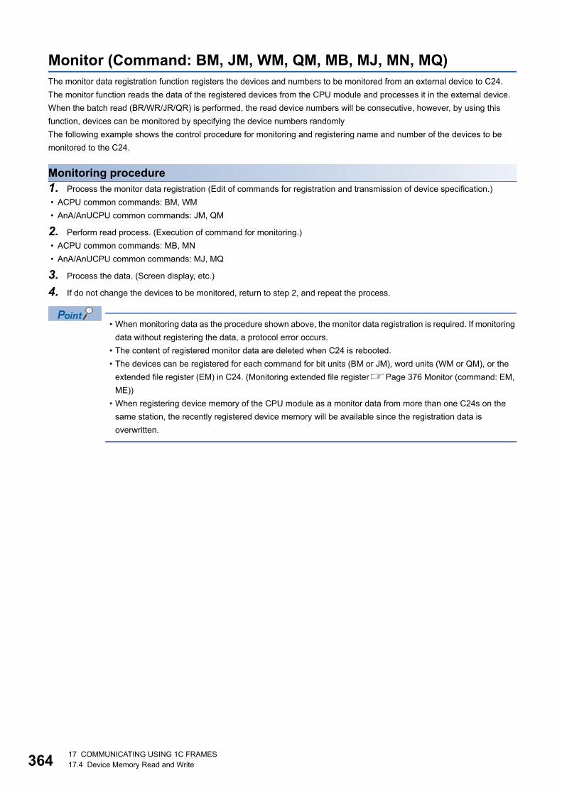
36417 COMMUNICATING USING 1C FRAMES17.4 Device Memory Read and Write
Monitor (Command: BM, JM, WM, QM, MB, MJ, MN, MQ)The monitor data registration function registers the devices and numbers to be monitored from an external device to C24.
The monitor function reads the data of the registered devices from the CPU module and processes it in the external device.
When the batch read (BR/WR/JR/QR) is performed, the read device numbers will be consecutive, however, by using this
function, devices can be monitored by specifying the device numbers randomly
The following example shows the control procedure for monitoring and registering name and number of the devices to be
monitored to the C24.
Monitoring procedure1. Process the monitor data registration (Edit of commands for registration and transmission of device specification.)
• ACPU common commands: BM, WM
• AnA/AnUCPU common commands: JM, QM
2. Perform read process. (Execution of command for monitoring.)
• ACPU common commands: MB, MN
• AnA/AnUCPU common commands: MJ, MQ
3. Process the data. (Screen display, etc.)
4. If do not change the devices to be monitored, return to step 2, and repeat the process.
• When monitoring data as the procedure shown above, the monitor data registration is required. If monitoring
data without registering the data, a protocol error occurs.
• The content of registered monitor data are deleted when C24 is rebooted.
• The devices can be registered for each command for bit units (BM or JM), word units (WM or QM), or the
extended file register (EM) in C24. (Monitoring extended file registerPage 376 Monitor (command: EM,
ME))
• When registering device memory of the CPU module as a monitor data from more than one C24s on the
same station, the recently registered device memory will be available since the registration data is
overwritten.

17 COMMUNICATING USING 1C FRAMES17.4 Device Memory Read and Write 365
17Register monitor data (bit units) (command: BM, JM)Set the bit devices (X, Y, M, etc.) to be monitored in 1-point units.
Monitor the device memory registered in bit units using the following command.
Page 367 Monitor (bit units) (command: MB, MJ)
■Request data
• Command
• Message wait: Specify the delayed time of the response transmission. (Page 345 Message wait)
• Number of device points: Convert the numerical value to 2-digit ASCII code (hexadecimal), and send it from the upper
digits.
• Device: Specify the devices to be monitored. (Page 349 Device codes, device numbers)
Specify the number of device points within the following range:
1 Number of device points 40
When using the BM command and accessing ACPU other than AnA/AnU, device X (input) has two processing
points per point.
■Response dataThere is no response data for this command.
■Communication example (Monitor data registration in bit units)Perform monitor data registration of the bit device under the following conditions.
• Message wait: 0 ms
• Number of device points: 3 points (3 bits)
• Device: Contacts of X40, Y060, and T123.
(Request data)
• When using BM (ACPU common command)
• When using JM (AnA/AnUCPU common command)
ACPU common AnA/AnUCPU common
Device(first point)
Device(nth point)
Number of device points
(n points)Command Message wait
B M42H 4DH
J M4AH 4DH
B M42H 4DH 58H
435H 34H 30H
0 330H 33H
0030H30H
0 X 059H
630H 36H 30H
0030H
Y 054H
231H 32H 33H
3S53H
T 1
Message waitNumber of device points DeviceDevice Device
J M4AH 4DH 58H
430H 34H 30H
0 330H 33H
0030H30H
0 X 0030H
030H 59H
630H 36H 30H
0030H
Y 054H
231H 32H 33H
3S53H
T 130H
030H
030H
030H
0
Message waitNumber of device points DeviceDevice Device

36617 COMMUNICATING USING 1C FRAMES17.4 Device Memory Read and Write
Register monitor data (word units) (command: WM, QM)Register the bit devices (X, Y, M, etc.) to be monitored in 16-point units.
Register the word devices (D, T, C, etc.) to be monitored in 1-point units.
A mixture of word devices and bit devices (16 bit units) can be specified.
Monitor the device memory registered in word units using the following command.
Page 368 Monitor (word units) (command: MN, MQ)
■Request data
• Command
• Message wait: Specify the delayed time of the response transmission. (Page 345 Message wait)
• Number of device points: Convert the numerical value to 2-digit ASCII code (hexadecimal), and send it from the upper
digits.
• Device: Specify the devices to be monitored. (Page 349 Device codes, device numbers)
Specify the number of device points within the following range:
1 Number of device points 20
When using the WM command and accessing ACPU other than AnA/AnU, device X (input) has two
processing points per point.
■Response dataThere is no response data for this command.
■Communication example (Monitor data registration in word units)Register the monitor data in a word unit under the following conditions.
• Message wait: 0 ms
• Number of device points: 4 points (4 words)
• Device: Current value of D15, W11E, and T123, and Y060 to Y06F
(Request data)
• When using WM (ACPU common command)
• When using QM (AnA/AnUCPU common command)
ACPU common AnA/AnUCPU common
Device(first point)
Device(nth point)
Number of device points
(n points)Command Message wait
W M57H 4DH
Q M51H 4DH
1 E0W 1 2 3NT 1 6 00Y 0W M 10 4 500 D 057H 4DH 44H 30H 31H 35H30H 34H 30H30H 57H 31H 31H 45H30H 54H 31H 32H 33H4EH 59H 30H 36H 30H30H
Message waitNumber of device points Device DeviceDevice Device
Q M51H 4DH 30H
0 430H 34H
030H30H
0 0030H
030H44H
131H 35H
5D57H
131H 31H 45H
EW 1 N4EH
59H
630H 36H 30H
0030H
Y 030H
030H
0
30H030H
054H
231H 32H 33H
3T 1030H 30H
030H
0
Message waitNumber of device points DeviceDevice Device
Device

17 COMMUNICATING USING 1C FRAMES17.4 Device Memory Read and Write 367
17Monitor (bit units) (command: MB, MJ)Monitor the registered bit devices (X, Y, M, etc.).
• The bit device memory registered with BM command is monitored using MB command.
• The bit device memory registered with JM command is monitored using MJ command.
■Request data
• Command
• Message wait: Specify the delayed time of the response transmission. (Page 345 Message wait)
■Response data
The value of read device is stored in bit units. (Page 72 Read data, write data)
■Communication exampleMonitor bit devices specified with monitor data registration under the following conditions.
• Message wait: 0 ms
• Registered devices for monitoring: 3 points (3 bits) of contacts for X040, Y060 and T123.
(Request data)
• When using MB (ACPU common command)
• When using MJ (AnA/AnUCPU common command)
(Response data)
ACPU common AnA/AnUCPU common
Message waitCommand
M B4DH 42H
M J4DH 4AH
Monitoring result ( For the number of device points )
M B4DH 42H
030H
Message wait
M J4DH 4AH
030H
Message wait
(X040) (Y060)
131H
030H
131H
Monitoring result ( For the number of device points )
(Contact of T123)

36817 COMMUNICATING USING 1C FRAMES17.4 Device Memory Read and Write
Monitor (word units) (command: MN, MQ)Monitor the registered bit devices (X, Y, M, etc.) in 16-point units.
Monitor the registered word device (D, T, C, etc.) in 1-point unit.
• The bit device memory registered with WM command is monitored using MN command.
• The bit device memory registered with QM command is monitored using MQ command.
■Request data
• Command
• Message wait: Specify the delayed time of the response transmission. (Page 345 Message wait)
■Response data
The value of read device is stored in word units. (Page 72 Read data, write data)
■Communication exampleMonitor bit devices or word devices specified with monitor data registration under the following conditions.
• Message wait: 0 ms
• Registered devices for monitoring: Current values of D15, W11E, T123, and 4 points (4 words) of Y060 to Y06F.
(Request data)
• When using MN (ACPU common command)
• When using MQ (AnA/AnUCPU common command)
(Response data)
ACPU common AnA/AnUCPU common
Message waitCommand
M N4DH 4EH
M Q4DH 51H
Monitoring result ( For the number of device points )
M N4DH 4EH
030H
Message wait
M Q4DH 51H
030H
Message wait
(D15) (W11E)32H 33H 34H31H 30H 35H 30H30H 34H30H 36H 34H30H 30H 37H 36H
0 0 0 0 0 1 1 1 0 1 1 0 0 1 0 0 1 2 3 4 0 0 5 0 0 0 6 4Monitoring result ( For the number of device points )
(Decimal : 4660) (Decimal : 80) (Decimal : 100)
(Current value of T123) (Y06F) to (Y06C) (Y06B) to (Y068) (Y067) to (Y064) (Y063) to (Y060)

17 COMMUNICATING USING 1C FRAMES17.5 Read and Write Extended File Register 369
1717.5 Read and Write Extended File RegisterThe extended file register is a memory area that stores required data and operation result for various data processing by
using the software package for extended file register 'SW0GHP-UTLPC-FN1' or 'SW0SRX-FNUP' (hereinafter abbreviated to
UTLP-FN1 and FNUP) and AnACPU and AnUSCPU extended file register dedicated instructions. The extended file register
uses free area of user memory area in CPU module as a file register.
The following example shows the control procedure to read and write extended file register.
Considerations for reading and writing extended file registerThe following shows the considerations when reading writing extended file register using the commands described in this
section.
Accessible CPU modulesOnly CPU modules that can handle the extended file register can be accessed.
This function cannot be used for CPU modules that cannot handle an extended file register (such as A1N).
Error detection for block numbers that do not exist Depending on the type of memory cassette inserted in the CPU module, an error (character area error '06H') may not be
detected even when a read/write operation is performed by specifying the block numbers that do not exist. In this case, the
read data is incorrect. If writing data to the CPU module, the user memory of the CPU module will be collapsed.
Check the type of memory cassette and parameter settings before using these functions.
*1 A3AMCA-96 can be used for A3A, A3U, and A4UCPU. For details, refer to the manual of UTLP-FN1 or FNUP, or user's manual of the access target CPU module.
Block numbers of extended file register that can be handled by A2USCPU(S1)The block numbers of the extended file register that can be handled by A2USCPU(S1) is as follows.
• A2USCPU: No.1 to 3
• A2USCPU-S1: No.1 to 8, No.10 to 16
Extended file register of R/L/Q/QnACPU The extended file register of R/L/Q/QnACPU cannot be read/written.
Memory cassette model name Block numbers that do not cause character area error (06H)
A0J2H, A2, A3CPU A2N, A3NCPU A3H, AnA, AnUCPU
A3NMCA-12 No.10 to No.11
A3NMCA-18 No.10 to No.28
A3NMCA-24 No.13 to No.20 No.13 to No.28
A3NMCA-40 No.21 to No.28
A3AMCA-96 No.21 to No.48*1

37017 COMMUNICATING USING 1C FRAMES17.5 Read and Write Extended File Register
Specification method for extended file registerThe specification method differs depending on the command.
• ACPU common command: Specify with device number and block number.
• AnA/AnUCPU common command: Specify the address from device number 0 of block number 1 as a device number.
(Access with the consecutive device number of extended file register using usable number of blocks 8192 points.)
Range of block number and device number that can be specifiedAn extended file register has blocks numbered from '0' to 'n' (the n differs depending on the memory cassette). Block number
'0' has a number of points registered with a parameter of the CPU module, while block numbers '1' to 'n' have a register of
8192 points in each block.
However, the range that can be read from or written to the CPU module will be the range specified in the parameter of 0 block.
The range of block numbers and device numbers that can be specified differ depending on the type of memory cassette and
the parameter setting in the CPU module. For details, refer to the operating manual of UTLP-FN1 or FNUP, or user's manuals
of AnACPU and AnUCPU.
• The AnA/AnUCPU common commands can be used for reading/writing data to the extended file register of
block number 1 to 256. In addition, the commands can be used regardless of the existence of file register
parameter.
• When accessing the file register (R) set by parameter or when accessing it by specifying block number, use
ACPU common commands.
0
0
8191
8191
0
81918192
1638316384
Device numbers specified with the ACPU common commands
Device numbers specified with the AnA/AnUCPU common commands
Area of block No.1
Block No.1
Area of block No.2
Block No.2
1 word 1 word
Device numbers are automatically assigned in ascending order beginning from the device with block No.1 to the device with block No.256.
to
to
to
to

17 COMMUNICATING USING 1C FRAMES17.5 Read and Write Extended File Register 371
17Device number (address) specification using AnA/AnUCPU common commandsBy using AnA/AnU common command function, the extended file register of block number 1 to 256 can be accessed
regardless of each block number by specifying the address from device number '0' of the block number '1' as a device
number. (Access with the consecutive device number of extended file register using usable number of blocks 8192 points.)
■Device number calculation methodThe calculation formula of the head device number to be specified by AnA/AnUCPU common commands is as follow:
(When specifying the device number 'm' (0 to 8191) of n block (more than 1) from the head of the block.)
Head device number = (n - 1) 8192 + m
■Range of device number that can be specifiedThe range of device number that can be specified are as follows.
0 to (number of available blocks 8192) - 1
A device number is not assigned to a block number which does not exist in the memory cassette. As shown below, the device
numbers are automatically assigned by skipping block numbers that do not exist in the memory cassette.
The following table shows the range of device numbers to be specified when using AnA/AnUCPU common commands for 28
blocks per each block.
Device number Position of target block Device number Position of target block
0 to 8191 First block R0 to R8191 114688 to 122879 15th block R0 to R8191
8192 to 16383 2nd block R0 to R8191 122880 to 131071 16th block R0 to R8191
16384 to 24575 3rd block R0 to R8191 131072 to 139263 17th block R0 to R8191
24576 to 32767 4th block R0 to R8191 139264 to 147455 18th block R0 to R8191
32768 to 40959 5th block R0 to R8191 147456 to 155647 19th block R0 to R8191
40960 to 49151 6th block R0 to R8191 155648 to 163839 20th block R0 to R8191
49152 to 57343 7th block R0 to R8191 163840 to 172031 21st block R0 to R8191
57344 to 65535 8th block R0 to R8191 172032 to 180223 22nd block R0 to R8191
65536 to 73727 9th block R0 to R8191 180224 to 188415 23rd block R0 to R8191
73728 to 81919 10th block R0 to R8191 188416 to 196607 24th block R0 to R8191
81920 to 90111 11th block R0 to R8191 196608 to 204799 25th block R0 to R8191
90112 to 98303 12th block R0 to R8191 204800 to 212991 26th block R0 to R8191
98304 to 106495 13th block R0 to R8191 212992 to 221183 27th block R0 to R8191
106496 to 114687 14th block R0 to R8191 221184 to 229375 28th block R0 to R8191
0
81918192
16383
16384
2457524576
Area of block No.1
Area of block No.2
Block No.3 to 9 do not exist
Area of block No.10
Area of block No.11to
to
to
to
Device number

37217 COMMUNICATING USING 1C FRAMES17.5 Read and Write Extended File Register
Data to be specified in command
Device number
■ACPU common commandSpecify the block number and device number with 7 digits.
• When the block number is less than 2 digits
'Block number (2 digits)' + 'R' + 'Device number (4 digits)'
• When the block number is 3 digits
'Block number (3 digits)' + 'Device number (4 digits)'
■AnA/AnUCPU common commandSpecify the address from device number 0 of block number 1 in 7 digits.
Page 371 Device number (address) specification using AnA/AnUCPU common commands
0 5 R 8 1 9 0 1 0 2 8 1 9 0
Specification example
When the block No. is less than 2 digits When the block No. is 3 digits
Device No. Device No.Block No. Block No.
Specification example 1
Specifying R10 of block number 1"0" in the first digits (for example, the leading three digits indicated in 0008200) can be specified by spaces (20H).
Specification example 2
Specifying R8 of block number 2
(2-1) × 8192+8
Block No. Block points
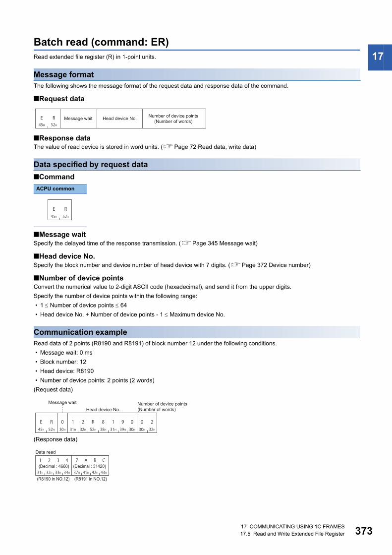
17 COMMUNICATING USING 1C FRAMES17.5 Read and Write Extended File Register 373
17Batch read (command: ER)Read extended file register (R) in 1-point units.
Message formatThe following shows the message format of the request data and response data of the command.
■Request data
■Response dataThe value of read device is stored in word units. (Page 72 Read data, write data)
Data specified by request data
■Command
■Message waitSpecify the delayed time of the response transmission. (Page 345 Message wait)
■Head device No.Specify the block number and device number of head device with 7 digits. (Page 372 Device number)
■Number of device pointsConvert the numerical value to 2-digit ASCII code (hexadecimal), and send it from the upper digits.
Specify the number of device points within the following range:
• 1 Number of device points 64
• Head device No. + Number of device points - 1 Maximum device No.
Communication exampleRead data of 2 points (R8190 and R8191) of block number 12 under the following conditions.
• Message wait: 0 ms
• Block number: 12
• Head device: R8190
• Number of device points: 2 points (2 words)
(Request data)
(Response data)
ACPU common
E R45H 52H
Message wait Head device No. Number of device points (Number of words)
E R45H 52H
E R45H 52H 31H
852H 38H 31H
0 230H 32H
1232H30H
0 1 R 939H 30H
0
Message wait Number of device points(Number of words)Head device No.
7 A B C1 2 3 4
32H 33H 34H31H 41H 42H 43H37H
Data read
(Decimal : 4660) (Decimal : 31420)
(R8190 in NO.12) (R8191 in NO.12)
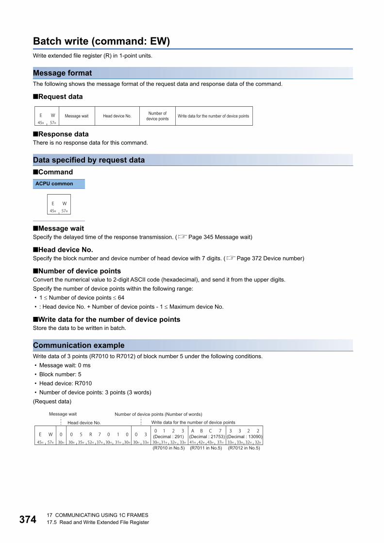
37417 COMMUNICATING USING 1C FRAMES17.5 Read and Write Extended File Register
Batch write (command: EW)Write extended file register (R) in 1-point units.
Message formatThe following shows the message format of the request data and response data of the command.
■Request data
■Response dataThere is no response data for this command.
Data specified by request data
■Command
■Message waitSpecify the delayed time of the response transmission. (Page 345 Message wait)
■Head device No.Specify the block number and device number of head device with 7 digits. (Page 372 Device number)
■Number of device pointsConvert the numerical value to 2-digit ASCII code (hexadecimal), and send it from the upper digits.
Specify the number of device points within the following range:
• 1 Number of device points 64
• : Head device No. + Number of device points - 1 Maximum device No.
■Write data for the number of device pointsStore the data to be written in batch.
Communication exampleWrite data of 3 points (R7010 to R7012) of block number 5 under the following conditions.
• Message wait: 0 ms
• Block number: 5
• Head device: R7010
• Number of device points: 3 points (3 words)
(Request data)
ACPU common
E W45H 57H
Message wait Head device No. Number of device points Write data for the number of device points
E W45H 57H
0 1 2 3 A B C 7 3 3 2 2E W45H 57H 30H
130H 31H 30H
0 330H 33H
0535H30H
0 0 0R52H
737H 32H 33H30H 31H 43H 37H41H 42H 32H 32H33H 33H
Message wait Number of device points (Number of words)
Write data for the number of device pointsHead device No.
(Decimal : 291) (Decimal : 21753) (Decimal : 13090)
(R7010 in No.5) (R7011 in No.5) (R7012 in No.5)

17 COMMUNICATING USING 1C FRAMES17.5 Read and Write Extended File Register 375
17Test (random write) (command: ET)Specify the block number and device number to the extended file register (R) in 1-point units and write them randomly.
Message formatThe following shows the message format of the request data and response data of the command.
■Request data
■Response dataThere is no response data for this command.
Data specified by request data
■Command
■Message waitSpecify the delayed time of the response transmission. (Page 345 Message wait)
■Number of device pointsConvert the numerical value to 2-digit ASCII code (hexadecimal), and send it from the upper digits.
Specify the number of device points within the following range:
• 1 Number of device points 10
■Device numberSpecify the block number and device number to be test with 7 digits. (Page 372 Device number)
■Write dataStore 4 characters per one device point.
Communication exampleWrite data of three points (3 words) randomly under the following conditions.
• Message wait: 0 ms
• Number of device points: 3 points (3 words)
• Device: Set R1234H to R1050 of block number 5, 1A1BH to R2121 of block number 7, and 506H to R3210 of block number
10.
(Request data)
ACPU common
E T45H 54H
Data for the number of device points
Message wait Device No. Write dataNumber of device points
E T45H 54H
E T45H 54H 30H
530H 35H 30H
0 330H 33H
0535H30H
0 0 0 332H 33H 34H
4131H
2R52H
131H
R52H
333H
30H2
31H 32H 31H17
37H0 1 1
41H 31H 42HB1
31HA
31H1
32H 31H 30H00
30H1 2 0
35H 30H 36H60
30H5
R52H
232H
Message waitNumber of device points Write data DeviceDevice
Write dataDevice
Write data

37617 COMMUNICATING USING 1C FRAMES17.5 Read and Write Extended File Register
Monitor (command: EM, ME)The monitor data registration function registers the devices and numbers to be monitored from an external device to C24.
The monitor function reads the data of the registered devices from the CPU module and processes it in the external device.
When the batch read (ER) or direct read (NR) is performed, the read device numbers will be consecutive, however, by using
this function, devices can be monitored by specifying the device numbers randomly.
The following example shows the control procedure for monitoring and registering name and number of the devices to be
monitored to the C24.
Monitoring procedure1. Process the monitor data registration (Edit of EM command and transmission of device specification.)
• Page 377 Register monitor data (command: EM)
2. Perform read process. (Execution of ME command)
• Page 378 Monitor (command: ME)
3. Process the data. (Screen display, etc.)
4. If do not change the devices to be monitored, return to step 2, and repeat the process.
• When monitoring data as the procedure shown above, the monitor data registration is required. If monitoring
data without registering the data, a protocol error occurs.
• The content of registered monitor data are deleted when C24 is rebooted.
• Five kinds of monitor data can be registered for the extended file register (EM), device memory in bit units
(BM or JM), and word units (WM or QM).
• When registering device memory of the CPU module as a monitor data from more than one external
devices on the same station, the recently registered device memory will be available since the registration
data is overwritten. (Monitoring device memory Page 364 Monitor (Command: BM, JM, WM, QM, MB,
MJ, MN, MQ))

17 COMMUNICATING USING 1C FRAMES17.5 Read and Write Extended File Register 377
17Register monitor data (command: EM)Register the device number to be monitored in 1-point units.
Monitor the extended file register registered with EM command using the following command.
Page 378 Monitor (command: ME)
■Request data
• Command
• Message wait: Specify the delayed time of the response transmission. (Page 345 Message wait)
• Number of device points: Convert the numerical value to 2-digit ASCII code (hexadecimal), and send it from the upper
digits.
• Device number: Specify the block number and device number of the device to be monitored with 7 digits. (Page 372
Device number)
Specify the number of device points within the following range:
1 Number of device points 20
■Response dataThere is no response data for this command.
■Communication examplePerform monitor data registration of 4 points (4 words) under the following conditions.
• Message wait: 0 ms
• Number of device points: 4 points (4 words)
• Device number: Register R1234 of block number 5, R2345 of block number 6, R3055 of block number 15, and R8000 of
block number 17.
(When the extended file register of block number 1 to 8 and 10 to 17 exist.)
ACPU common
E M45H 4DH
Message wait Number of device points
Device No. ( for the number of device points)
E M45H 4DH
E M45H 4DH 32H
0 430H 34H
535H30H
0 2R52H
131H30H
333H 34H
4030H
433H 34H 35H
50 3 535H
31H
052H 30H 30H
0737H
1 R30H
838H
0
52H636H
R31H
530H 35H 35H
51 0232H 33H
R52H
3
Message waitNumber of device points Device No. Device No. Device No.
Device No.

37817 COMMUNICATING USING 1C FRAMES17.5 Read and Write Extended File Register
Monitor (command: ME)Monitor the registered extended file registers.
■Message format • Request data
• Response data
The value of read device is stored in word units. (Page 72 Read data, write data)
■Data specified by request data • Command
• Message wait: Specify the delayed time of the response transmission. (Page 345 Message wait)
■Communication exampleMonitor data of 4 points (4 word) specified with monitor data registration under the following conditions.
• Message wait: 0 ms
• Registered devices for monitoring: R1234 of block number 5, R2345 of block number 6, R3055 of block number 15, and 4-
point of R8000 of block number 17.
(Request data)
(Response data)
ACPU common
M E4DH 45H
Message wait
Monitoring result ( For the number of device points )
M E4DH 45H
M E4DH 45H
030H
Message wait
1 C 2 D0 1 5 04 F 5 B3 5 0 1
35H 30H 31H33H 46H 35H 42H34H 31H 35H 30H30H 43H 32H 44H31H
Monitoring result ( For the number of device points )
(Decimal : 13569) (Decimal : 20315) (Decimal : 366) (Decimal : 366)
(R1234 in No.5) (R2345 in No.6) (R3055 in No.15) (R800 in No.17)

17 COMMUNICATING USING 1C FRAMES17.5 Read and Write Extended File Register 379
17Direct read (command: NR)Read extended file register in 1-point (1 word) units by specifying the consecutive device number of extended file register.
Message formatThe following shows the message format of the request data and response data of the command.
■Request data
■Response dataThe value of read device is stored in word units. (Page 72 Read data, write data)
Data specified by request data
■Command
■Message waitSpecify the delayed time of the response transmission. (Page 345 Message wait)
■Head device No.Specify the device number of head device with 7 digits. (Page 372 Device number)
■Number of device pointsConvert the numerical value to 2-digit ASCII code (hexadecimal), and send it from the upper digits.
Specify the number of device points within the following range:
• 1 Number of device points 64
• Head device No. + Number of device points - 1 Maximum device No.
Communication exampleRead data of 2 points (R8190 and R8191) of block number 2 under the following conditions.
• Message wait: 0 ms
• Block number: 2
• Head device: R8190
• Number of device points: 2 points (2 words)
(Request data)
(Response data)
ACPU common
N R4EH 52H
Message wait Head device No. Number of device points (Number of words)
N R4EH 52H
N R4EH 52H 30H
831H 38H 32H
0 230H 32H
2030H30H
0 0 133H
636H
3
Message wait
Head device No.Number of device points (Number of words)
7 A B C1 2 3 4
32H 33H 34H31H 41H 42H 43H37H
Data read
(Decimal : 4660) (Decimal : 31420)
(R8190 in No.2) (R8191 in No.2)

38017 COMMUNICATING USING 1C FRAMES17.5 Read and Write Extended File Register
Direct write (command: NW)Write extended file register in 1-point (1 word) units by specifying the consecutive device number of extended file register.
Message formatThe following shows the message format of the request data and response data of the command.
■Request data
■Response dataThere is no response data for this command.
Data specified by request data
■Command
■Message waitSpecify the delayed time of the response transmission. (Page 345 Message wait)
■Head device No.Specify the device number of head device with 7 digits. (Page 372 Device number)
■Number of device pointsConvert the numerical value to 2-digit ASCII code (hexadecimal), and send it from the upper digits.
Specify the number of device points within the following range:
• 1 Number of device points 64
• Head device No. + Number of device points - 1 Maximum device No.
■Write data for the number of device pointsStore 4-digit data per one device point.
Communication exampleWrite data of 3 points under the following conditions.
• Message wait: 0 ms
• Write data: Write R8190 and R8191 of block number 12 and RO of block number 13.
(When the extended file register of block number 1 to 8 and 10 to 13 exist.)
• Number of device points: 3 points (3 words)
(Request data)
ACPU common
N W4EH 57H
Message wait Head device No.Number of
device points Write data for the number of device points
N W4EH 57H
N W4EH 57H 30H
131H 31H 30H
0 330H 33H
0030H30H
0 0 1939H
030H 33H 32H 32H33H31H 32H 33H30H 42H 43H 37H41H
3 3 2 2A B C 70 1 2 3
Message wait Number of device points (Number of words)
Head device No. Write data for the number of device points
(Decimal : 291) (Decimal : 21753) (Decimal : 13090)
(R8190 in No.12) (R8191 in No.12) (R0 in No.13)

17 COMMUNICATING USING 1C FRAMES17.6 Read and write Buffer Memory of Special Function Module 381
1717.6 Read and write Buffer Memory of Special Function
ModuleThe following examples the commands that performs data read/write to the buffer memory of MELSEC-A series special
function modules.
This command accesses in byte units regardless of the word/byte specification.
Data to be specified in commandThis section explains the contents and specification methods for data items which are set in each command related to the
access to the special function module buffer memory.
For details of the specification method of address and module number for commands (TR, TW), refer to the following manual.
Computer Link Module (Com. link func./Print. func.) User's Manual
Start addressSpecify the start address of the buffer memory to be read/written.
Convert the numerical value to 5-digit ASCII code (hexadecimal), and send it from the upper digits.
■Calculation methodCalculate the start address as follows:
Start address = (Buffer memory address 2) + the arbitrary additional value of a module
For the additional values (buffer memory start address) for each module, refer to the following section.
Page 383 Accessible modules
Ex.
When specifying buffer memory address 1H of AD61
(1H2) + 80H = 82H
Byte lengthSpecify the byte length of the special function module buffer memory data to be read/written.
Convert the numerical value to 2-digit ASCII code (hexadecimal), and send it from the upper digits.
Read data, write dataThe read buffer memory value is stored for reading, and the data to be written is stored for writing.
This function reads/writes data in byte unit.
Page 159 Read data, write data

38217 COMMUNICATING USING 1C FRAMES17.6 Read and write Buffer Memory of Special Function Module
Special function module No.Specify the last input/output signal (I/O address) of the special function module. (Specify the upper 2-digit in 3-digit
representation.)
Convert the numerical value to 2-digit ASCII code (hexadecimal), and send it from the upper digits.
■Special function module No. which occupies 1 slotSpecial function module No. is the upper 2 digits of the input/output signal (I/O address) of the last number represented with 3-
digits on the slot where the module is mounted.
■Special function module No. which occupies 2 slotsFor a special function module which occupies two slots, the number of occupied points for each slot is fixed for each module.
Special function module No. specified for the operation procedure is the upper 2 digits of the input/output signal (I/O address)
of the last number represented with 3-digits of the slot assigned as a special function module on the slot.
For details of the assigned slot for each module, refer to the manual of the modules.
Ex.
A module that assign the first part of the slots as empty slots (AD72, A84AD, etc.)
Ex.
A module that assign the last part of the slots as empty slots (A61LS, etc.)
Ex.
A module in which both assignment of special function module and I/O assignment exist (A81CPU)
Special function module
Special function module
Power supplymodule
CPU module Input Output Input Output Input Output
16 points 32 points16 points 16 points 32 points 32 points32 points 32 points
Module No. "0AH"Special function module
Power supplymodule
Module No. "07H"Input Output Output Output
32 points 32 points16 points 32 points 32 points
Module No. "13H"
00 to 0F 10 to 2F 30 to 4F 50 to 5F 60 to 7F 80 to 8F 90 to AF B0 to CF
D0 to DF E0 to FF 100 to 11F 120 to 13F 140 to 15F
Special function module
(Empty slot)
Module No. "02H"
16 points 32 points
00 to 0F 10 to 2F
Special function module
(Empty slot)
Module No. "01H"
16 points32 points
00 to 0F 20 to 2F
Special function module
Input module
Module No. "03H"
64 points64 points
00 to 3F 40 to 7F

17 COMMUNICATING USING 1C FRAMES17.6 Read and write Buffer Memory of Special Function Module 383
17Accessible modulesThe accessible special function modules are as follows.
Module Type Additional values when calculating start address(Buffer memory start address)
Module number when module is mounted on slot 0
High-speed counter module AD61 (S1) 80H 01H
A1SD61, A1SD62 (E/D) 10H 01H
Analog-digital converter module A616AD 10H 01H
A68AD(S2), A68ADN 80H 01H
A84AD 10H 02H
A1S64AD 10H 01H
Digital-analog converter module A616DAI, A616DAV
A62DA (S1)
A68DAV/DAI
A1S62DA
10H 01H
Temperature-digital converter module A616TD
A68RD3/4
A1S62RD3/4
10H 01H
PID control module A81CPU 200H 03H
Position detection module A61LS 80H 01H
A62LS (S5) 80H 02H
MELSECNET/MINI master module AJ71PT32 (S3), AJ71T32-S3
A1SJ71PT32-S3
20H 01H
CC-Link system master/local module AJ61BT11 2000H 01H
A1SJ61BT11 2000H 01H
Multidrop link module AJ71C22 (S1) 1000H 01H
Computer link module AJ71C24 (S3/S6/S8) 1000H 01H
AJ71UC24
A1SJ71 (U) C24-R2
A1SJ71 (U) C24-PRF
A1SJ71 (U) C24-R4
400H 01H
Intelligent communication module AD51H (S3), AD51H (S3) 800H 02H
Terminal interface module AJ71C21 (S1) 400H 01H
B/NET interface module AJ71B62 20H 01H
SUMINET interface module AJ71P41 400H 01H
Ethernet interface module AJ71E71 (S3) 400H 01H
A1SJ71E71 (S3) 4000H 01H
External fault diagnosis module AD51FD (S3) 280H 02H
Graphic controller module AD57G (S3) 280H 02H
Vision sensor module AS25VS, AS50VS 100H 02H
AS50VS-GN 80H 02H
Memory card interface module AD59 (S1) 1800H 01H
Positioning module AD70 (D) (S2) 80H 01H
AD71 (S1/S2/S7) 200H 01H
AD72
A1SD71-S2/S7
200H 02H
AD75P1/P2/P3 (S3), AD75M1/M2/M3
A1SD75P1/P2/P3 (S3), A1SD75M1/M2/
M3
800H 01H
Positioning module for 1 axis A1SD70 80H 01H
Analog input/output module A1S63ADA 10H 01H
Temperature control module A1S64TCTT (BW)-S1
A1S64TCRT (BW)-S1
A1S64TCTRT (BW)
A1S62TCTT (BW)-S2
A1S62TCRT (BW)-S2
20H 01H
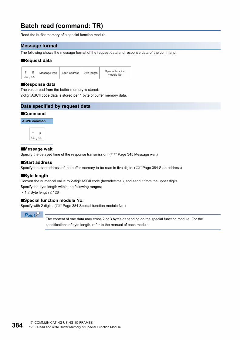
38417 COMMUNICATING USING 1C FRAMES17.6 Read and write Buffer Memory of Special Function Module
Batch read (command: TR)Read the buffer memory of a special function module.
Message formatThe following shows the message format of the request data and response data of the command.
■Request data
■Response dataThe value read from the buffer memory is stored.
2-digit ASCII code data is stored per 1 byte of buffer memory data.
Data specified by request data
■Command
■Message waitSpecify the delayed time of the response transmission. (Page 345 Message wait)
■Start addressSpecify the start address of the buffer memory to be read in five digits. (Page 384 Start address)
■Byte lengthConvert the numerical value to 2-digit ASCII code (hexadecimal), and send it from the upper digits.
Specify the byte length within the following ranges:
• 1 Byte length 128
■Special function module No.Specify with 2 digits. (Page 384 Special function module No.)
The content of one data may cross 2 or 3 bytes depending on the special function module. For the
specifications of byte length, refer to the manual of each module.
ACPU common
T R54H 52H
Message wait Byte length Special function module No.Start address
T R54H 52H

17 COMMUNICATING USING 1C FRAMES17.6 Read and write Buffer Memory of Special Function Module 385
17Communication exampleRead data of 4 bytes under the following conditions.
• Message wait: 0 ms
• Start address: 7FOH
• Byte length: 4 bytes
• Special function module No.: 13 (input/output signals are 120H to 13FH)
(Request data)
(Response data)
T R54H 52H 30H
F37H 46H 30H
0 430H 34H
0030H30H
0 0 731H
333H
1
Message wait Start address Byte length Special function module No.
7F0H
32H31H 38H37H 33H34H 35H36H
7F2H
7812H
6543H (7F2H)
(7F0H)6 54 37 81 2
Data readBuffer memoryStart address

38617 COMMUNICATING USING 1C FRAMES17.6 Read and write Buffer Memory of Special Function Module
Batch write (command: TW)Write data to the buffer memory of a special function module.
Message formatThe following shows the message format of the request data and response data of the command.
■Request data
■Response dataThere is no response data for this command.
Data specified by request data
■Command
■Message waitSpecify the delayed time of the response transmission. (Page 345 Message wait)
■Start addressSpecify the start address of the buffer memory to be written in five digits. (Page 384 Start address)
■Byte lengthConvert the numerical value to 2-digit ASCII code (hexadecimal), and send it from the upper digits.
Specify the byte length within the following ranges:
• 1 Byte length 128
■Special function module No.Specify in two characters. (Page 384 Special function module No.)
■Write dataStore the data written to buffer memory.
The content of one data may cross 2 or 3 bytes depending on the special function module. For the
specifications of byte length, refer to the manual of each module.
Communication exampleWrite data of 4 bytes under the following conditions.
• Message wait: 0 ms
• Start address: 27FAH
• Byte length: 4 bytes
• Special function module No.: 13 (input/output signals are 120H to 13FH)
(Request data)
ACPU common
T W54H 57H
Message wait Start address Write dataByte length Special function module No.
T W54H 57H
CD01H
EFABH (27FCH)
(27FAH)
27FAH 27FCH
T W54H 57H 30H
F37H 46H 41H
0 430H 34H
A232H30H
0 0 731H
333H
130H
D43H 44H
131H
0 C41H
F45H 46H
B42H
A E
Special function module No.Message wait
Start address Write dataByte length Buffer memoryStart address

17 COMMUNICATING USING 1C FRAMES17.7 Loopback Test 387
1717.7 Loopback TestA loopback test checks whether the communication function between an external device and C24 operates normally.
Loopback test (Command: TT)Return the characters received from an external device to the external device unchanged.
Message formatThe following shows the message format of the request data and response data of the command.
■Request data
■Response data
Data specified by request data
■Command
■Message waitSpecify the delayed time of the response transmission. (Page 345 Message wait)
■Character lengthConvert the numerical value to 2-digit ASCII code (hexadecimal), and send it from the upper digits.
Specify the character length within the following range:
• 1 Character length 254
■Loopback dataStore the loopback data for character length.
Data stored by response data
■Character lengthThe same data as request data is stored.
■Loopback dataThe same data as request data is stored.
Specify 'FF' for PC No.
ACPU common
T T54H 54H
Message wait Loopback data
Character length
Loopback data
Character length
T T54H 54H
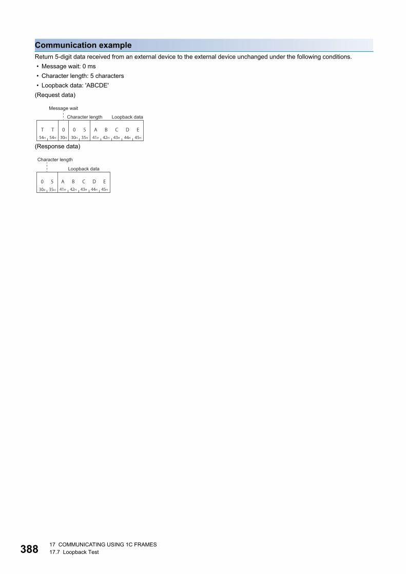
38817 COMMUNICATING USING 1C FRAMES17.7 Loopback Test
Communication exampleReturn 5-digit data received from an external device to the external device unchanged under the following conditions.
• Message wait: 0 ms
• Character length: 5 characters
• Loopback data: 'ABCDE'
(Request data)
(Response data)
T T54H 54H 41H
D43H 44H 45H
0 530H 35H
EB42H30H
0 A C
Message wait
Character length Loopback data
41HD
43H 44H 45H0 530H 35H
EB42H
A C
Character length
Loopback data
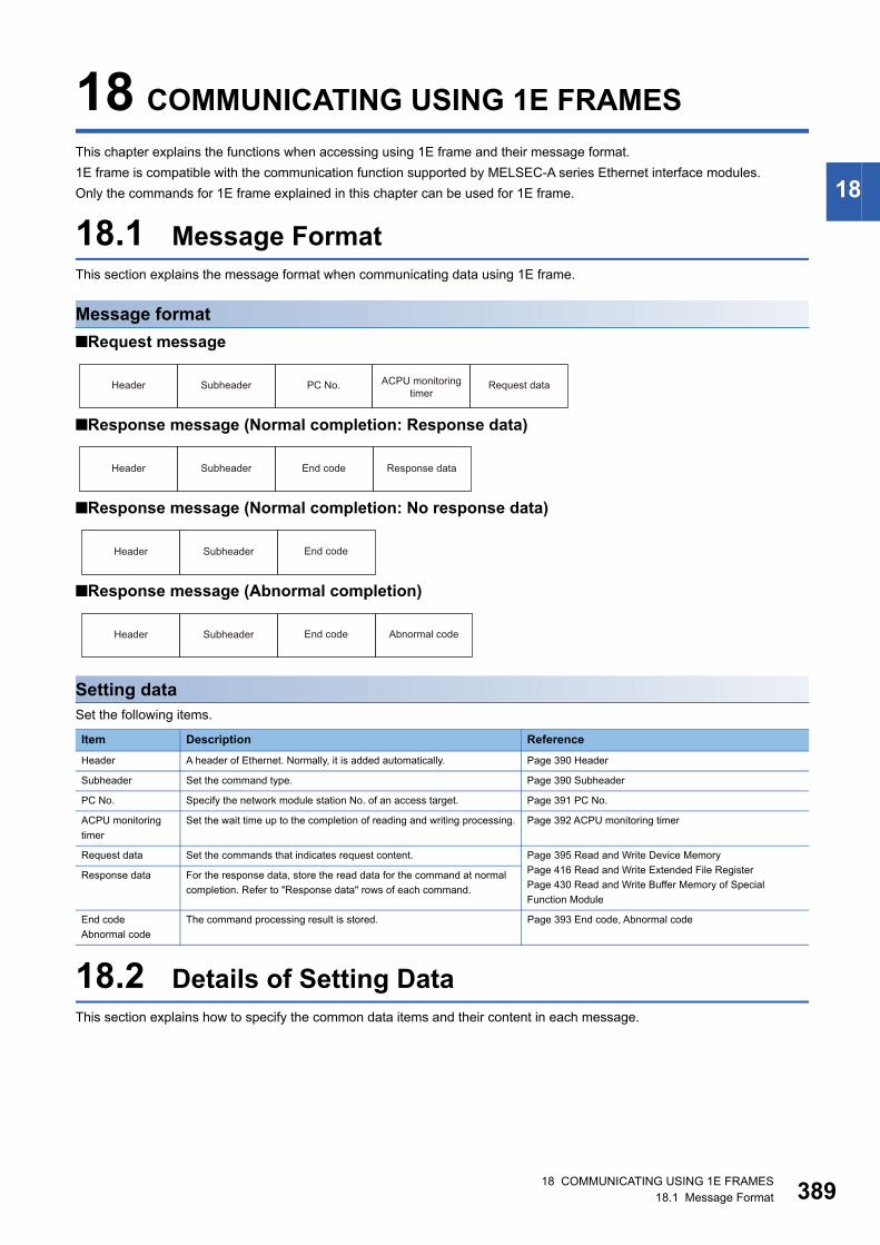
18 COMMUNICATING USING 1E FRAMES18.1 Message Format 389
18
18 COMMUNICATING USING 1E FRAMES
This chapter explains the functions when accessing using 1E frame and their message format.
1E frame is compatible with the communication function supported by MELSEC-A series Ethernet interface modules.
Only the commands for 1E frame explained in this chapter can be used for 1E frame.
18.1 Message FormatThis section explains the message format when communicating data using 1E frame.
Message format
■Request message
■Response message (Normal completion: Response data)
■Response message (Normal completion: No response data)
■Response message (Abnormal completion)
Setting dataSet the following items.
18.2 Details of Setting DataThis section explains how to specify the common data items and their content in each message.
Item Description Reference
Header A header of Ethernet. Normally, it is added automatically. Page 390 Header
Subheader Set the command type. Page 390 Subheader
PC No. Specify the network module station No. of an access target. Page 391 PC No.
ACPU monitoring
timer
Set the wait time up to the completion of reading and writing processing. Page 392 ACPU monitoring timer
Request data Set the commands that indicates request content. Page 395 Read and Write Device Memory
Page 416 Read and Write Extended File Register
Page 430 Read and Write Buffer Memory of Special
Function Module
Response data For the response data, store the read data for the command at normal
completion. Refer to "Response data" rows of each command.
End code
Abnormal code
The command processing result is stored. Page 393 End code, Abnormal code
Header Subheader PC No. ACPU monitoring timer
Request data
Header Subheader End code Response data
End codeHeader Subheader
End code Abnormal codeHeader Subheader

39018 COMMUNICATING USING 1E FRAMES18.2 Details of Setting Data
HeaderA header for TCP/IP and UDP/IP. A header of a request message is added on the external device side and sent. Normally, it
is added automatically by an external device. A header for a response message is set automatically by E71.
SubheaderSet the command type. (Page 394 Commands and Function List for 1E Frame)
The setting values for each command are as follows.
Setting method
■Data communication in ASCII codeConvert the numerical value to 2-digit ASCII code (hexadecimal), and send it from the upper digits.
■Data communication in binary codeSend a 1-byte numerical value.
Ex.
Device memory batch read (word units)
Request message
Response message
Function Subheader Reference
Request message
Response message
Read and write device memory 00H 80H Page 401 Batch read in bit units (command: 00)
01H 81H Page 403 Batch read in word units (command: 01)
02H 82H Page 405 Batch write in bit units (command: 02)
03H 83H Page 407 Batch write in word units (command: 03)
04H 84H Page 408 Test in bit units (random write) (command: 04)
05H 85H Page 410 Test in word units (random write) (command: 05)
06H 86H Page 413 Register monitor data(command: 06, 07)
07H 87H Page 413 Register monitor data(command: 06, 07)
08H 88H Page 414 Monitor in bit units (command: 08)
09H 89H Page 415 Monitor in word units (command: 09)
Read and write extended file register 17H 97H Page 417 Batch read (command: 17)
18H 98H Page 419 Batch write (command: 18)
19H 99H Page 421 Test (random write) (command: 19)
1AH 9AH Page 424 Register monitor data (command: 1A)
1BH 9BH Page 425 Monitoring (command: 1B)
3BH BBH Page 426 Direct read (command: 3B)
3CH BCH Page 428 Direct write (command: 3C)
Read and write buffer memory of special
function module
0EH 8EH Page 432 Batch read (command: 0E)
0FH 8FH Page 434 Batch write (command: 0F)
ASCII code Binary code
ASCII code Binary code
30H 30H
0 000H
38H 30H
8 080H

18 COMMUNICATING USING 1E FRAMES18.2 Details of Setting Data 391
18
PC No.Specify the station No. of the access target.
Accessing the connected station (host station)Specify 'FF'.
Accessing other stations via networkSpecify the network module station No.01H to 40H (1 to 64) of the access target.
Setting method
■Data communication in ASCII codeConvert the numerical value to 2-digit ASCII code (hexadecimal), and send it from the upper digits.
■Data communication in binary codeSend a 1-byte numerical value.
Ex.
Accessing the connected station (host station)
When accessing other station of network station No. '3'.
The station No. of the network module can be checked by using the following parameters of Engineering tool.
• GX Developer and GX Works2: "Network Parameter"
• GX Works3: "Module Parameter"
The network module station No. is set in decimal. However, the PC No. is set in hexadecimal.
When specifying the network of the access target is required, set "Valid Module During Other Station Access"
with an Engineering tool.
ASCII code Binary code
ASCII code Binary code
External device
Connected station(Host station) :Access target station
External device
Network
Other station
Connected station (host station)
:Access target station
46H 46H
F FFFH
30H 33H
0 303H

39218 COMMUNICATING USING 1E FRAMES18.2 Details of Setting Data
ACPU monitoring timerSet the wait time up to the completion of reading and writing processing.
• 0000H (0): Wait infinitely (Waits until a processing is completed.)
• 0001H to FFFFH (1 to 65535): Waiting time (unit: 250 ms)
To perform normal data communication, using the timer within the setting range in the table below is recommended depending
on the communication destination.
When accessing QnACPU or ACPU for the first time, the wait time for CPU monitoring timer is required before
receiving a response message because QnACPU identifies the CPU type. Be sure to set a value within the
range of recommended range.
Setting method
■Data communication in ASCII codeConvert the numerical value to 4-digit ASCII code (hexadecimal), and send it from the upper digits.
■Data communication in binary codeSend 2-byte numerical values from lower byte (L: bits 0 to 7).
Ex.
When specifying '10H' for the monitoring timer
Access target The recommended value for monitoring timer
Connected station (host station) 1H to 28H (0.25 s to 10 s)
Other station 2H to F0H (0.5 s to 60 s)
ASCII code Binary code
30H 31H 30H30H
0 0 1 0
10H 00H

18 COMMUNICATING USING 1E FRAMES18.2 Details of Setting Data 393
18
End code, Abnormal codeThe command processing result is stored.
End codeAt normal completion, '0' is stored.
At abnormal completion, an error code of the access target is stored.
Error code indicates the content of occurred error.
If more than one error occurs at the same time, the error code detected first is returned.
For the content of error code and its corrective action, refer to the user's manual of the module used.
QCPU User's Manual (Hardware Design, Maintenance and Inspection)
MELSEC-L CPU Module User's Manual (Hardware Design, Maintenance and Inspection)
Q Corresponding Ethernet Interface Module User's Manual (Basic)
MELSEC-L Ethernet Interface Module User's Manual (Basic)
Abnormal codeWhen an end code is '5BH', the details of abnormal content are displayed.
Setting method
■Data communication in ASCII codeConvert the numerical value to 2-digit ASCII code (hexadecimal), and send it from the upper digits.
■Data communication in binary codeUse a 1-byte value.
Ex.
Normal completion
When Error code '10H' is returned
When error code '5BH' and an abnormal code '10H' (PC No. error) are returned,
ASCII code Binary code
ASCII code Binary code
ASCII code Binary code
0 030H 30H 00H
31H 30H
1 0
10H
42H 31H 30H35H
5 B 1 0
5BH 10H

39418 COMMUNICATING USING 1E FRAMES18.3 Commands and Function List for 1E Frame
18.3 Commands and Function List for 1E Frame Use the following commands for data communication using 1E frame.
*1 Use the dedicated commands for extended registers when performing extended file registers read/write.*2 The devices that can be registered to E71 is for 1 command out of the three types of commands (06H, 07H, 1AH).
The specified device recently used by any of the above commands is registered to E71.
Function Command Description
Device memory*1 Batch read Bit units 00H Reads bit devices (X, Y, M, etc.) in 1-point units.
Word units 01H Reads bit devices (X, Y, M, etc.) in 16-point units.
Reads word devices (D, T, C, etc.) in 1-point units.
Batch write Bit units 02H Writes bit devices (X, Y, M, etc.) in 1-point units.
Word units 03H Writes bit devices (X, Y, M, etc.) in 16-point units.
Writes word devices (D, T, C, etc.) in 1-point units.
Test
(random write)
Bit units 04H Specify the devices and device numbers of bit devices (X, Y, M, etc.) in 1-point
units randomly, and set/reset them.
Word units 05H Specify the devices and device numbers of bit devices (X, Y, M, etc.) in 16-
point units randomly, and set/reset them.
Specify the devices and device numbers of word devices (D, T, C, etc.) in 1-
point units randomly, and write them.
Register monitor
data*2Bit units 06H Registers bit devices (X, Y, M, etc.) to be monitored in 1-point units
Word units 07H Registers bit devices (X, Y, M, etc.) to be monitored in 16-point units.
Registers word devices (D, T, C, etc.) to be monitored in 1-point units.
Monitoring Bit units 08H Monitors the devices registered by monitor data registration.
Word units 09H
Extended file register Batch read 17H Reads extended file register (R) in 1-point units.
Batch write 18H Writes extended file register (R) in 1-point units.
Test
(random write)
19H Specify the block numbers and device numbers in 1-point units and write them
to the extended file register (R) randomly.
Register monitor data*2 1AH Registers extended file register (R) in 1-point units.
Monitoring 1BH Monitors extended file register (R) with monitor data registered.
Direct read 3BH Reads extended file register in 1-point units with direct designation.
Direct write 3CH Writes extended file register in 1-point units by direct specification.
Special function
module
Batch read 0EH Reads the content in the buffer memory of a special function module.
Batch write 0FH Writes data to the buffer memory of a special function module.

18 COMMUNICATING USING 1E FRAMES18.4 Read and Write Device Memory 395
18
18.4 Read and Write Device MemoryThis section explains the specification content and examples of the request data and the response data when reading and
writing device memory.
For the message formats other than request data and response data, refer to the following sections.
Page 389 Message Format, Page 389 Details of Setting Data
To read and write the extended file register, use the commands dedicated to the extended file register.
Page 416 Read and Write Extended File Register
Considerations
Considerations when reading/writing data to module other than ACPU module
■Accessible devicesOnly the devices with the same names that exist in ACPU can be accessed within the device range of AnACPU.
The following devices cannot be accessed from the external devices
• Added devices
• Latch relay (L) and step relay (S)
• File register (R)
■Special relays and special registersSpecial relays and special registers can be accessed within the following range.
• Access SM1000 to SM1255 by specifying M9000 to M9255.
• Access SD1000 to SD1255 by specifying D9000 to D9255.
■Universal model QCPUUse the Universal model QCPU with a serial number whose first five digits are '10102' or later.
When the module with the serial number whose first five digits are '10101' or earlier, access using 3E frame or 4E frame.
When accessing the built-in Ethernet port of the CPU module, refer to the following manual.
QnUCPU User's Manual (Communication via Built-in Ethernet Port)
Data to be specified in command
Device codes and device numbersThe settings of each device when reading/writing device memory can be performed using device code and device number as
shown in the following figure.
Specify the device to be accessed by a device code and a device number.
The order of data differs depending on the ASCII code or binary code.
■Data communication in ASCII code • Device code: Convert the numerical value to 4-digit ASCII code (hexadecimal), and send it from the upper digits.
• Device number: Convert the numerical value to 8-digit (hexadecimal) ASCII code, and send it from the upper digits.
■Data communication in binary code • Device number: Send 4-byte numerical values from the lower byte (L: bits 0 to 7).
• Device code: Send 2-byte numerical values from lower byte (L: bits 0 to 7).
ASCII code Binary code
Device code Device number
(4 digits) (8 digits)
Device number Device code
(4 bytes) (2 bytes)

39618 COMMUNICATING USING 1E FRAMES18.4 Read and Write Device Memory
Ex.
Data register (D) 1234 (device number is decimal)
Convert a device number to hexadecimal. '1234' (decimal)'4D2' (hexadecimal)
For the values of each device code, refer to the following section.
: Space
Access the devices within the range that can be used in the access target CPU.
For the accessible device range, refer to the following section.
Page 397 Accessible device range
• For word unit specification, the head device number of bit device must be specified in multiple of 16.
• For special relay M9000 or later, (9000 + multiple of 16) can be specified.
ASCII code Binary code
Device name Symbol Type Representation Device code
Input X Bit Hexadecimal X 5820H
Output Y Bit Hexadecimal Y 5920H
Internal relay (include in latch relay and step relay) M/L/S Bit Decimal M 4D20H
Annunciator F Bit Decimal F 4620H
Link relay B Bit Hexadecimal B 4220H
Timer Current value T Word Decimal TN 544EH
Contact Bit Decimal TS 5453H
Coil Bit Decimal TC 5443H
Counter Current value C Word Decimal CN 434EH
Contact Bit Decimal CS 4353H
Coil Bit Decimal CC 4343H
Data register D Word Decimal D 4420H
Link register W Word Hexadecimal W 5720H
File register R Word Decimal R 5220H
4 4 234H 34H 32H
030H
0 0 030H 30H 30H
030H
0 4 D30H 34H 44H
232H D2H 04H 00H 00H 20H 44H

18 COMMUNICATING USING 1E FRAMES18.4 Read and Write Device Memory 397
18
Accessible device range
■List of devices (ACPU other than AnU)Specify the device number within the range of the access target module.
: Accessible, : No device
• Do not write data to the devices which cannot be written in the range of the special relays (M9000 to M9255)
and special registers (D9000 to D9255). For details on the special relays and special registers, refer to
manual of ACPU to be accessed.
• For L and S, perform accessing by specifying 'M' (For example, to access L100, specify M100.)
Device Device range Device number A1SA1SHA1SJA1SJHA1A1N
A2SA2SHA2A2NA2CA2CJA0J2H
A2-S1A2N-S1
A3A3N
A2A A2A-S1 A3A
Input X0 to X0FF 0000H to 00FFH
X100 to X1FF 0100H to 01FFH
X200 to X3FF 0200H to 03FFH
X400 to X7FF 0400H to 07FFH
Output Y0 to Y0FF 0000H to 00FFH
Y100 to Y1FF 0100H to 01FFH
Y200 to Y3FF 0200H to 03FFH
Y400 to Y7FF 0400H to 07FFH
Internal relay
(Including latch relay and step
relay)
M0 to M2047 0000H to 07FFH
M2048 to M8191 0800H to 1FFFH
M9000 to M9255 2328H to 2427H
Annunciator F0 to F255 0000H to 00FFH
F256 to F2047 0100H to 07FFH
Link relay B0 to B3FF 0000H to 03FFH
B400 to BFFF 0400H to 0FFFH
Timer Current value T0 to T255 0000H to 00FFH
T256 to T2047 0100H to 07FFH
Contact T0 to T255 0000H to 00FFH
T256 to T2047 0100H to 07FFH
Coil T0 to T255 0000H to 00FFH
T256 to T2047 0100H to 07FFH
Counter Current value C0 to C255 0000H to 00FFH
C256 to C1023 0100H to 03FFH
Contact C0 to C255 0000H to 00FFH
C256 to C1023 0100H to 03FFH
Coil C0 to C255 0000H to 00FFH
C256 to C1023 0100H to 03FFH
Data register D0 to D1023 0000H to 03FFH
D1024 to D6143 0400H to 17FFH
D9000 to D9255 2328H to 2427H
Link register W0 to W3FF 0000H to 03FFH
W400 to WFFF 0400H to 0FFFH
File register R0 to R4095 0000H to 0FFFH
R4096 to R8191 1000H to 1FFFH

39818 COMMUNICATING USING 1E FRAMES18.4 Read and Write Device Memory
■List of devices (AnUCPU, QnACPU)Specify the device within the range of AnACPU.
Page 395 Considerations when reading/writing data to module other than ACPU module
: Accessible, : Not accessible, : No device
• Do not write data to the devices which cannot be written in the range of the special relays (M9000 to M9255)
and special registers (D9000 to D9255). For details on the special relays and special registers, refer to the
programming manual of ACPU.
• For L and S, perform accessing by specifying 'M' (For example, to access L100, specify M100.)
Device Device range Device number A2USA2U
A2US-S1A2USH-S1A2U-S1
A3UA4U
Q2AQ2ASQ2ASH
Q2A-S1Q2AS-S1Q2ASH-S1
Q3AQ4AQ4AR
Input X0 to X1FF 0000H to 01FFH
X200 to X3FF 0200H to 03FFH
X400 to X7FF 0400H to 07FFH
Output Y0 to Y1FF 0000H to 01FFH
Y200 to Y3FF 0200H to 03FFH
Y400 to Y7FF 0400H to 07FFH
Internal relay
(Including latch relay and step relay)
M0 to M8191 0000H to 1FFFH
M9000 to M9255
(SM1000 to
SM1255)
2328H to 2427H
Annunciator F0 to F2047 0000H to 07FFH
Link relay B0 to BFFF 0000H to 0FFFH
Timer Current value T0 to T2047 0000H to 07FFH
Contact T0 to T2047 0000H to 07FFH
Coil T0 to T2047 0000H to 07FFH
Counter Current value C0 to C1023 0000H to 03FFH
Contact C0 to C1023 0000H to 03FFH
Coil C0 to C1023 0000H to 03FFH
Data register D0 to D6143 0000H to 17FFH
D9000 to D9255
(SD1000 to SD1255)
2328H to 2427H
Link register W0 to WFFF 0000H to 0FFFH
File register R0 to R8191 0000H to 1FFFH

18 COMMUNICATING USING 1E FRAMES18.4 Read and Write Device Memory 399
18
■Device list (QCPU, LCPU, safety CPU)Specify the device within the range of AnACPU.
Page 395 Considerations when reading/writing data to module other than ACPU module
: Accessible, : Not accessible, : No device
Device Device range Device number
Basic model QCPUSafety CPU
QCPU other than leftLCPU
Input X0 to X7FF 0000H to
07FFH
Output Y0 to Y7FF 0000H to
07FFH
Internal relay M0 to M8191 0000H to
1FFFH
M9000 to M9255
(SM1000 to
SM1255)
2328H to 2427H
Annunciator F0 to F1023 0000H to
03FFH
F1024 to F2047 0400H to
07FFH
Link relay B0 to B7FF 0000H to
07FFH
B800 to BFFF 0800H to
0FFFH
Timer Current
value
T0 to T511 0000H to
01FFH
T512 to T2047 0200H to
07FFH
Contact T0 to T511 0000H to
01FFH
T512 to T2047 0200H to
07FFH
Coil T0 to T511 0000H to
01FFH
T512 to T2047 0200H to
07FFH
Counter Current
value
C0 to C511 0000H to
01FFH
C512 to C1023 0200H to
03FFH
Contact C0 to C511 0000H to
01FFH
C512 to C1023 0200H to
03FFH
Coil C0 to C511 0000H to
01FFH
C512 to C1023 0200H to
03FFH
Data register D0 to D6143 0000H to
17FFH
D9000 to D9255
(SD1000 to SD1255)
2328H to 2427H
Link register W0 to W7FF 0000H to
07FFH
W800 to WFFF 0800H to
0FFFH
File register R0 or more 0000H or more
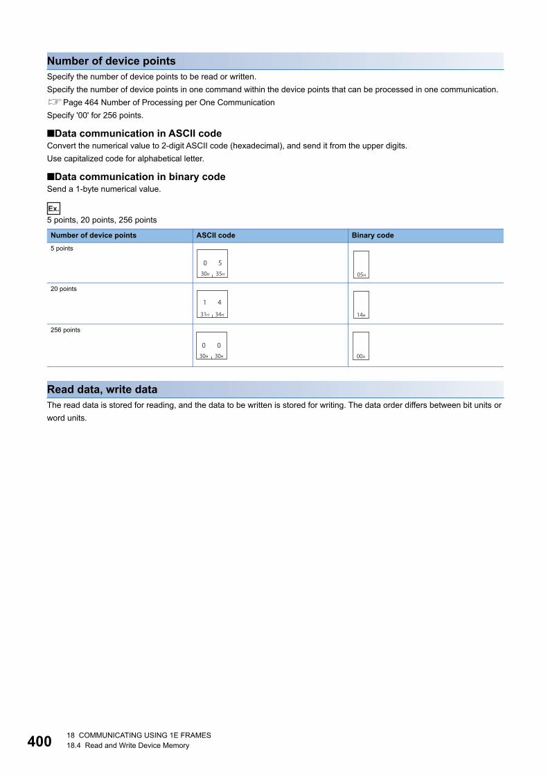
40018 COMMUNICATING USING 1E FRAMES18.4 Read and Write Device Memory
Number of device pointsSpecify the number of device points to be read or written.
Specify the number of device points in one command within the device points that can be processed in one communication.
Page 464 Number of Processing per One Communication
Specify '00' for 256 points.
■Data communication in ASCII codeConvert the numerical value to 2-digit ASCII code (hexadecimal), and send it from the upper digits.
Use capitalized code for alphabetical letter.
■Data communication in binary codeSend a 1-byte numerical value.
Ex.
5 points, 20 points, 256 points
Read data, write dataThe read data is stored for reading, and the data to be written is stored for writing. The data order differs between bit units or
word units.
Number of device points ASCII code Binary code
5 points
20 points
256 points
30H 35H
0 505H
31H 34H
1 4
14H
30H 30H
0 000H

18 COMMUNICATING USING 1E FRAMES18.4 Read and Write Device Memory 401
18
Batch read in bit units (command: 00)Read bit devices (X, Y, M, etc.) in 1-point units.
Message formatThe following shows the message format of the request data and response data of the command.
Specify the command type by subheader. (Page 390 Subheader)
■Request data
■Response dataThe data for the number of device points are stored.
(Page 400 Read data, write data)
For ASCII code, when the number of device points are specified in an odd number, one byte of dummy data
(30H) will be added to the response data. For example, if a data for three points are read, data for four points
is returned. The last byte will be a dummy data.
Data specified by request data
■Head deviceSpecify the head device number of bit devices to be read. (Page 395 Device codes and device numbers)
■Number of device pointsSpecify the number of the bit device points to be read.
Specify '00H' when the number of device points is to 256 points. (Page 400 Number of device points)
■Fixed valueFixed to '0'.
ASCII code Binary code
Number of device points
Head device Fixed value
030H
030H 00H

40218 COMMUNICATING USING 1E FRAMES18.4 Read and Write Device Memory
Communication exampleRead the bit devices in the CPU module with E71 mounted under the following conditions.
• Head device: M100
• Number of device points: 12 points
■Data communication in ASCII code(Request data)
(Response data)
■Data communication in binary code(Request data)
(Response data)
34H 44H 32H 30H 30H 30H 30H 30H 30H 30H 36H 34H 30H 43H 30H 30H
4 D 2 0 0 0 0 0 0 0 6 4 0 C 0 0
Head device Number of device points
31H 30H 31H 30H 31H 30H 31H 30H 31H 30H 31H 30H
1 0 1 0 1 0 1 0 1 0 1 0
(M100) (M111)
Data for the number of specified device points
to
64H 00H 00H 00H 20H 4DH 0CH 00H
Head device Number of device points
10H 10H 10H 10H 10H 10H
1 0 1 0 1 0 1 0 1 0 1 0
Data for the number of specified device points
(M100) to (M111)

18 COMMUNICATING USING 1E FRAMES18.4 Read and Write Device Memory 403
18
Batch read in word units (command: 01)Reads bit devices (X, Y, M, etc.) in 16-point units.
Reads word devices (D, T, C, etc.) in 1-point units
Message formatThe following shows the message format of the request data and response data of the command.
■Request data
■Response dataThe data for the number of device points are stored.
The order of data differs depending on the ASCII code or binary code. (Page 400 Read data, write data)
Data specified by request data
■Head deviceSpecify the head device of the device to be read. (Page 395 Device codes and device numbers)
■Number of device pointsSpecify the device number to be read.
Specify '00H' when the number of device points is to 256 points. (Page 400 Number of device points)
When specifying bit devices, set the head device No. in multiples of 16 (0, 16, ... in decimal notation).
■Fixed valueFixed to '0'.
ASCII code Binary code
Number of device points
Head device Fixed value
030H
030H 00H

40418 COMMUNICATING USING 1E FRAMES18.4 Read and Write Device Memory
Communication exampleRead the bit devices in the CPU module with E71 mounted under the following conditions.
• Head device: Y40
• Number of device points: 32 points (2 bytes)
■Data communication in ASCII code(Request data)
(Response data)
■Data communication in binary code(Request data)
(Response data)
35H 39H 32H 30H 30H 30H 30H 30H 30H 30H 34H 30H 30H 32H 30H 30H
5 9 2 0 0 0 0 0 0 0 4 0 0 2 0 0
Head device Number of device points
32H38H 44H39H 35H35H 45H33H
1 0 0 1 1 1 0 11 0 0 0 0 0 1 0 0 0 1 1 1 1 1 00 1 0 1 0 1 0 1
8 2 9 D 5 5 3 E
82H 9DH 55H 3EH
Data for the number of specified device points
(Y4F) to (Y48) (Y47) to (Y40) (Y5F) to (Y58) (Y57) to (Y50)
40H 00H 00H 00H 20H 59H 02H 00H
Head device Number of device points
9DH 82H 3EH 55H
1 0 0 1 1 1 0 1 1 0 0 0 0 0 1 0 0 0 1 1 1 1 1 0 0 1 0 1 0 1 0 1
82H9DH 55H3EH
Data for the number of specified device points
(Y47) to (Y40) (Y4F) to (Y48) (Y57) to (Y50) (Y5F) to (Y58)
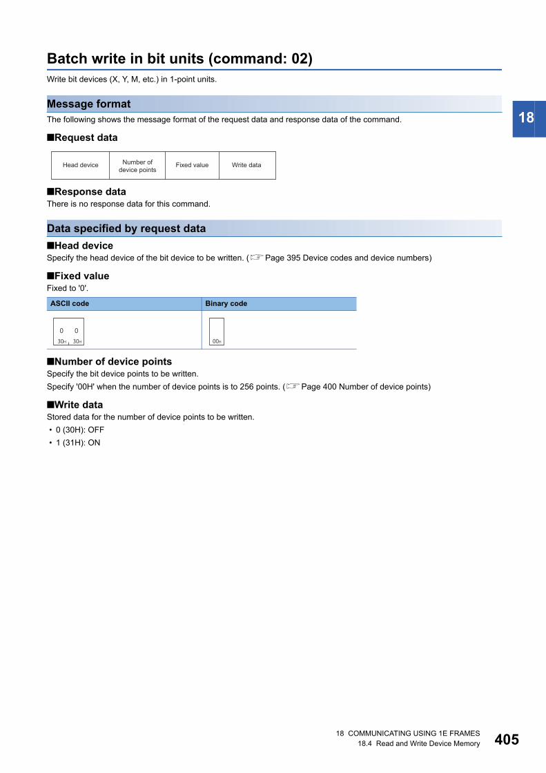
18 COMMUNICATING USING 1E FRAMES18.4 Read and Write Device Memory 405
18
Batch write in bit units (command: 02)Write bit devices (X, Y, M, etc.) in 1-point units.
Message formatThe following shows the message format of the request data and response data of the command.
■Request data
■Response dataThere is no response data for this command.
Data specified by request data
■Head deviceSpecify the head device of the bit device to be written. (Page 395 Device codes and device numbers)
■Fixed valueFixed to '0'.
■Number of device pointsSpecify the bit device points to be written.
Specify '00H' when the number of device points is to 256 points. (Page 400 Number of device points)
■Write dataStored data for the number of device points to be written.
• 0 (30H): OFF
• 1 (31H): ON
ASCII code Binary code
Head device Number of device points
Fixed value Write data
030H
030H 00H

40618 COMMUNICATING USING 1E FRAMES18.4 Read and Write Device Memory
Communication exampleWrite the bit devices in the CPU module with E71 mounted under the following conditions.
• Head device: M50
• Number of device points: 12 points
■Data communication in ASCII code(Request data)
■Data communication in binary code(Request data)
34H 44H 32H 30H 30H 30H 30H 30H 30H 30H 33H 32H 30H 43H 30H 30H 31H 31H 30H 31H
4 4 2 0 0 0 0 0 0 0 3 2 0 3 0 0 1 1 0 1
(M50) (M61)
Head device Number of device points Data for the number of specified device points
to
32H 00H 00H 00H 20H 4DH 0CH 00H 01H 11H 01H 00H 00H 01H
0 1 1 1 0 1 0 0 0 0 0 1
Number of device pointsHead device Data for the number of specified device points
(M50) to (M61)

18 COMMUNICATING USING 1E FRAMES18.4 Read and Write Device Memory 407
18
Batch write in word units (command: 03)Write bit devices (X, Y, M, etc.) in 16-point units.
Write word devices (D, T, C, etc.) in 1-point units.
Message formatThe following shows the message format of the request data and response data of the command.
■Request data
■Response dataThere is no response data for this command.
Data specified by request data
■Head deviceSpecify the head device of the device to be written.
■Number of device pointsSpecify the number of device points to be written.
Specify '00H' when the number of device points is to 256 points.
When specifying bit devices, set the head device No. in multiples of 16 (0, 16, ... in decimal notation).
■Fixed valueFixed to '0'.
■Write dataStored data for the number of device points to be written.
The order of data differs depending on the ASCII code or binary code. (Page 400 Read data, write data)
Communication exampleWrite the devices in the CPU module with E71 mounted under the following conditions.
• Head device: D100
• Number of device points: 3 points
■Data communication in ASCII code(Request data)
■Data communication in binary code(Request data)
ASCII code Binary code
Head device Number of device points
Fixed value Write data
030H
030H 00H
34H 34H 32H 30H 30H 30H 30H 30H 30H 30H 36H 34H 33H30H 30H30H 32H31H 34H33H 38H39H 36H37H 31H30H 39H30H
4 4 2 0 0 0 0 0 0 0 6 4 0 3 0 0 1 2 3 4 9 8 7 6 0 1 0 9
(D100) (D101) (D102)
Data for the number of specified device pointsNumber of device pointsHead device
03H 00H64H 00H 00H 00H 20H 44H 34H 12H 76H 98H 09H 01H(D100) (D101) (D102)
Head device Number of device points Data for the number of specified device points

40818 COMMUNICATING USING 1E FRAMES18.4 Read and Write Device Memory
Test in bit units (random write) (command: 04)Specify the devices and device numbers of bit devices (X, Y, M, etc.) in 1-point units randomly, and set/reset them.
Message formatThe following shows the message format of the request data and response data of the command.
■Request dataThere is no request data for this command.
■Response dataThere is no response data for this command.
Data specified by request data
■Number of device pointsSpecify the number of points of the bit device to be set/reset. (Page 400 Number of device points)
■Fixed valueFixed to '0'.
■Specified deviceSpecify the bit devices to be set/reset. (Page 395 Device codes and device numbers)
■ON/OFF specificationSpecify set/reset.
ASCII code Binary code
Processing ASCII code Binary code
Reset
Set
Specified device(first point)
ON/OFF specification(first point)
Specified device(nth point)
ON/OFF specification(nth point)
Number of device points
(n points)Fixed value
030H
030H 00H
030H
030H 00H
030H
131H 01H

18 COMMUNICATING USING 1E FRAMES18.4 Read and Write Device Memory 409
18
Communication exampleSet/reset the bit devices in CPU module with E71 mounted under the following conditions.
• Number of device points: 3 points
• Data for the number of specified device points: Specify Y94 to ON, M60 to OFF, and B26 to ON.
■Data communication in ASCII code(Request data)
■Data communication in binary code(Request data)
35H 39H 32H 30H 30H 30H 30H 30H 30H 30H 39H 34H 30H 31H30H 30H30H 33H
34H 44H 32H 30H 30H 30H 30H 30H 30H 30H 33H 43H 30H 30H
34H 32H 32H 30H 30H 30H 30H 30H 30H 30H 32H 36H 30H 31H
5 9 2 0 0 0 0 0 0 0 9 4
4 D 2 0 0 0 0 0 0 0 3 C
4 2 2 0 0 0 0 0 0 0 2 6
0 3 0 0 0 1
0 0
0 1
(Y94)
(M60)
(B26)
(OFF)
(ON)
(ON)
Specified device(first point)
ON/OFF specification(first point)
Number of device points
Specified device(second point)
ON/OFF specification(second point)
Specified device(third point)
ON/OFF specification(third point)
03H 00H 94H 00H 00H 00H 20H 59H 01H 3CH 00H 00H 00H 20H 4DH 00H 26H 00H 00H 00H 20H 42H 01H(Y94) (M60) (B26)(ON) (ON)(OFF)
Number of device points
Specified device(first point)
ON/OFF specification(first point)
Specified device(second point)
ON/OFF specification(second point)
Specified device(third point)
ON/OFF specification(third point)
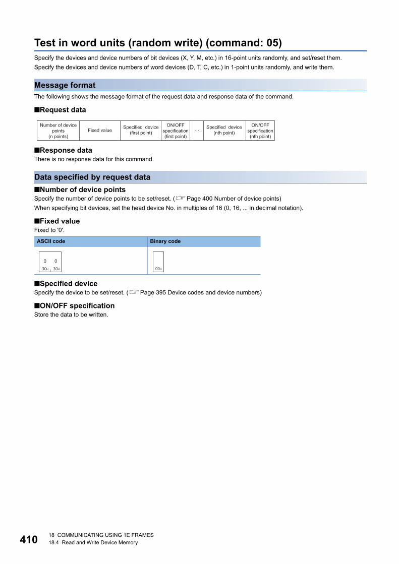
41018 COMMUNICATING USING 1E FRAMES18.4 Read and Write Device Memory
Test in word units (random write) (command: 05)Specify the devices and device numbers of bit devices (X, Y, M, etc.) in 16-point units randomly, and set/reset them.
Specify the devices and device numbers of word devices (D, T, C, etc.) in 1-point units randomly, and write them.
Message formatThe following shows the message format of the request data and response data of the command.
■Request data
■Response dataThere is no response data for this command.
Data specified by request data
■Number of device pointsSpecify the number of device points to be set/reset. (Page 400 Number of device points)
When specifying bit devices, set the head device No. in multiples of 16 (0, 16, ... in decimal notation).
■Fixed valueFixed to '0'.
■Specified deviceSpecify the device to be set/reset. (Page 395 Device codes and device numbers)
■ON/OFF specificationStore the data to be written.
ASCII code Binary code
Specified device(first point)
ON/OFF specification(first point)
Specified device(nth point)
ON/OFF specification(nth point)
Number of device points
(n points)Fixed value
030H
030H 00H
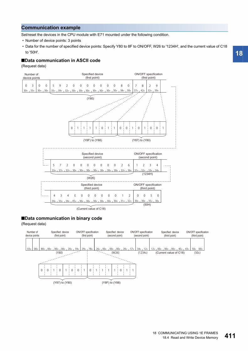
18 COMMUNICATING USING 1E FRAMES18.4 Read and Write Device Memory 411
18
Communication exampleSet/reset the devices in the CPU module with E71 mounted under the following condition.
• Number of device points: 3 points
• Data for the number of specified device points: Specify Y80 to 8F to ON/OFF, W26 to '1234H', and the current value of C18
to '50H'.
■Data communication in ASCII code(Request data)
■Data communication in binary code(Request data)
35H 39H 32H 30H 30H 30H 30H 30H 30H 30H 38H 30H 37H 42H30H 30H30H 33H
35H 37H 32H 30H 30H 30H 30H 30H 30H 30H 32H 36H
34H 33H 34H 45H 30H 30H 30H 30H 30H 30H 31H 32H
32H 39H
31H 32H 33H 34H
30H 30H 35H 30H
7 B 2 9
0 1 1 1 1 0 1 1 0 0 1 0 1 0 0 1
5 9 2 0 0 0 0 0 0 0 8 0
5 7 2 0 0 0 0 0 0 0 2 6
4 3 4 E 0 0 0 0 0 0 1 2
0 3 0 0
1 2 3 4
0 0 5 0
Number of device points
Specified device (first point)
ON/OFF specification(first point)
ON/OFF specification (second point)
ON/OFF specification (third point)
Specified device (second point)
Specified device (third point)
(Current value of C18)
(Y80)
(Y87) to (Y80)(Y8F) to (Y88)
(50H)
(1234H)(W26)
03H 00H 80H 00H 00H 00H 20H 59H(Y80)
26H 00H 00H 00H 20H 57H 12H 00H 00H 00H 4EH 43H34H 12H 50H 00H(W26)
29H 7BH
0 1 1 1 1 0 1 10 0 1 0 1 0 0 1
(1234H) (50H)
Number of device points
Specified device(first point)
ON/OFF specification(first point)
Specified device(second point)
ON/OFF specification(second point)
Specified device(third point)
ON/OFF specification(third point)
(Current value of C18)
(Y87) to (Y80) (Y8F) to (Y88)

41218 COMMUNICATING USING 1E FRAMES18.4 Read and Write Device Memory
Monitor device memory (command: 06, 07, 08, 09)The ON/OFF status or contents of devices in the CPU module can be monitored from an external device by registering the
devices and device numbers to be monitored to E71 in advance and executing the monitor command from the external
device.
When reading device memory in batch, the read device numbers will be consecutive. However, when reading them using the
monitor command, the devices can be monitored randomly by specifying the arbitrary devices and device numbers.
For monitoring the extended file register, refer to the following section.
Page 423 Monitor extended file registers (command: 1A, 1B)
Procedure for monitoring1. Register the devices to be monitored from the external device to E71 by registering monitor data.
2. Execute the read processing by a monitor command.
3. Process the data.
4. If do not change the devices to be monitored, return to step 2, and repeat the process.
• When monitoring data as the procedure shown above, the monitor data registration is required. If monitoring
data without registering the data, a protocol error occurs.
• The content of registered monitor data is deleted when turning the power OFF or the resetting the CPU
module.
• There are three types of commands for monitor data registration; expansion file register, device memory bit
unit, and device memory word unit. The recently registered one command out of three types of commands
can be registered to E71.
• When registering device memory of the CPU module as a monitoring data from more than one external
devices on the same station, the recently registered device memory will be available since the registration
data is overwritten.

18 COMMUNICATING USING 1E FRAMES18.4 Read and Write Device Memory 413
18
Register monitor data(command: 06, 07)Registers bit devices (X, Y, M, etc.) to be monitored in 1-point units. (Command: 06)
Registers bit devices (X, Y, M, etc.) to be monitored in 16-point units. (Command: 07)
Registers word devices (D, T, C, etc.) to be monitored in 1-point units. (Command: 07)
■Request data
• Number of device points: Specify the number of devices to be registered as a monitoring data. (Page 400 Number of
device points)
• Fixed value: '0'.
• Device number: Specify the device number to be registered as a monitor data. (Page 395 Device codes and device
numbers)
When specifying bit devices at monitor data registration in word unit, set the device numbers in multiples of 16
( 0, 16, ... in decimal notation).
■Response dataThere is no response data for this command.
■Communication exampleRegister devices as a monitoring data in the CPU module with E71 mounted under the following conditions.
• Number of device points: 3 points
• Device number: Y46, M12, B2C
(Request data)
(ASCII code)
(Binary code)
ASCII code Binary code
Device number(first point)
Device number(nth point)
Number of device points(n points)
Fixed value
030H
030H 00H
35H 39H 32H 30H 30H 30H 30H 30H 30H 30H 34H 36H30H 30H30H 33H
34H 44H 32H 30H 30H 30H 30H 30H 30H 30H 30H 43H 34H 32H 32H 45H 30H 30H 30H 30H 30H 30H 32H 43H
5 9 2 0 0 0 0 0 0 0 4 6
4 D 2 0 0 0 0 0 0 0 0 C 4 2 2 E 0 0 0 0 0 0 2 C
0 3 0 0
(Y46)
(M12) (B2C)
Number of device points Device number
Device number Device number
03H 00H 46H 00H 00H 00H 20H 59H 0CH 00H 00H 00H 20H 4DH 2CH 00H 00H 00H 20H 42H(Y46) (M12) (B2C)
Number of device points Device number Device number Device number

41418 COMMUNICATING USING 1E FRAMES18.4 Read and Write Device Memory
Monitor in bit units (command: 08)Monitor the bit devices for which monitor data is registered.
■Request dataThere is no request data for this command.
■Response dataThe value of the read device is stored in byte units.
The order of data differs depending on the ASCII code or binary code.
If the number of device points registered to be monitored is an odd number, dummy data 0 (30H) is added
when the monitoring is executed. For example, if the number of device points registered to be monitored is
three points, data for four points is returned. The last byte will be a dummy data.
■Communication exampleMonitor the devices registered with monitor data registration in the CPU module with E71 mounted under the following
conditions.
• Number of registered device points: 3 points
• Number of registered device numbers: Y46, M12, B2C
(Response data)
(ASCII code)
(Binary code)
30H30H38H 38H 31H 30H 31H 30H
(Y46)(M12)
(B2C)
8 8 0 0 1 0 1 0
End code Data for the number of specified device points
Subheader
Dummy data
88H 00H
1 0 1 0
(Y46)(M12)
(B2C)
10H 10H
Subheader End code Data for the number of specified device points
Dummy data

18 COMMUNICATING USING 1E FRAMES18.4 Read and Write Device Memory 415
18
Monitor in word units (command: 09)Monitor word devices and bit devices (16 point units) which are registered as a monitor data.
■Request dataThere is no request data for this command.
■Response dataThe value of the read device is stored in word units.
The order of data differs depending on the ASCII code or binary code.
■Communication exampleMonitor the devices registered with monitor data registration in the CPU module with E71 mounted under the following
conditions.
• Number of registered device numbers: Y50 to 5F, D38, W1E
(Response data)
(ASCII code)
(Binary code)
30H30H38H 39H 35H45H 44H36H 32H31H 34H33H 36H35H 38H37H(D38) (W1E)
0 1 1 0 1 1 0 11 1 1 0 0 1 0 1
E 5 6 D8 9 0 0 1 2 3 4 5 6 7 8
End code
Subheader Data for the number of specified device points
(Y5F) to (Y58) (Y57) to (Y50)
89H 00H 34H 12H 78H 56H(D38) (W1E)
6DH E5H
0 1 1 0 1 1 0 1 1 1 1 0 0 1 0 1
Subheader End code Data for the number of specified device points
(Y5F) to (Y58)(Y57) to (Y50)
41618 COMMUNICATING USING 1E FRAMES18.5 Read and Write Extended File Register
18.5 Read and Write Extended File RegisterThe extended file register is a memory area that stores required data and operation result for various data processing and
AnACPU and AnUSCPU extended file register dedicated instructions by using the software package for extended file register
'SW0GHP-UTLPC-FN1' or 'SW0SRX-FNUP' (hereinafter abbreviated to UTLP-FN1 and FNUP). The extended file register
uses free area of user memory area in CPU module as a file register.
This section explains the commands for reading and writing extended file register.
For the message formats other than request data and response data, refer to the following sections.
Page 389 Message Format, Page 389 Details of Setting Data
For the considerations when reading and writing extended file register, refer to the following section.
Page 369 Considerations for reading and writing extended file register
For the specification method of the extended file register, refer to the following section.
Page 370 Specification method for extended file register
Data to be specified in command
Block numberSpecify the block number of the extended file register.
■Data communication in ASCII codeConvert the numerical value to 4-digit ASCII code (hexadecimal), and send it from the upper digits.
■Data communication in binary codeSend 2-byte numerical value.
Device numberSpecify the device number of the extended file register.
When reading or writing (command: 3B, 3C) extended file register directly, refer to the following section.
Page 371 Device number (address) specification using AnA/AnUCPU common commands
■Data communication in ASCII codeConvert the numerical value to 12-digit ASCII code (hexadecimal), and send it from the upper digits.
■Data communication in binary codeSend 6-byte numerical value.
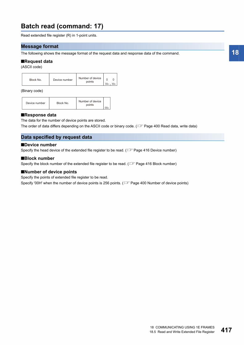
18 COMMUNICATING USING 1E FRAMES18.5 Read and Write Extended File Register 417
18
Batch read (command: 17)Read extended file register (R) in 1-point units.
Message formatThe following shows the message format of the request data and response data of the command.
■Request data(ASCII code)
(Binary code)
■Response dataThe data for the number of device points are stored.
The order of data differs depending on the ASCII code or binary code. (Page 400 Read data, write data)
Data specified by request data
■Device numberSpecify the head device of the extended file register to be read. (Page 416 Device number)
■Block numberSpecify the block number of the extended file register to be read. (Page 416 Block number)
■Number of device pointsSpecify the points of extended file register to be read.
Specify '00H' when the number of device points is 256 points. (Page 400 Number of device points)
30H30H0 0Block No. Device number Number of device
points
00H
Device number Block No. Number of device points

41818 COMMUNICATING USING 1E FRAMES18.5 Read and Write Extended File Register
Communication exampleRead the extended file registers in the CPU module with E71 mounted under the following conditions.
• Block number: No.2
• Device number: R70
• Number of device points: 3 points
■Data communication in ASCII code(Request data)
(Response data)
■Data communication in binary code(Request data)
(Response data)
35H 32H 32H 30H 30H 30H 30H 30H 30H 30H 34H 36H 33H30H 30H30H30H30H 32H30H
5 2 2 0 0 0 0 0 0 0 4 60 0 0 2 0 3 0 0
Block No. Device number Number of device points
31H 32H 33H 34H 38H 37H 36H 35H 30H 31H 33H 46H
0 1 3 F8 7 6 51 2 3 4
Data for the number of specified device points
(R70 in No.2) (R71 in No.2) (R72 in No.2)
03H 00H46H 00H 00H 00H 20H 52H 02H 00H
Number of device pointsBlock No.Device number
12H34H 87H65H 01H3FH
Data for the number of specified device points
(R70 in No.2) (R72 in No.2)(R71 in No.2)
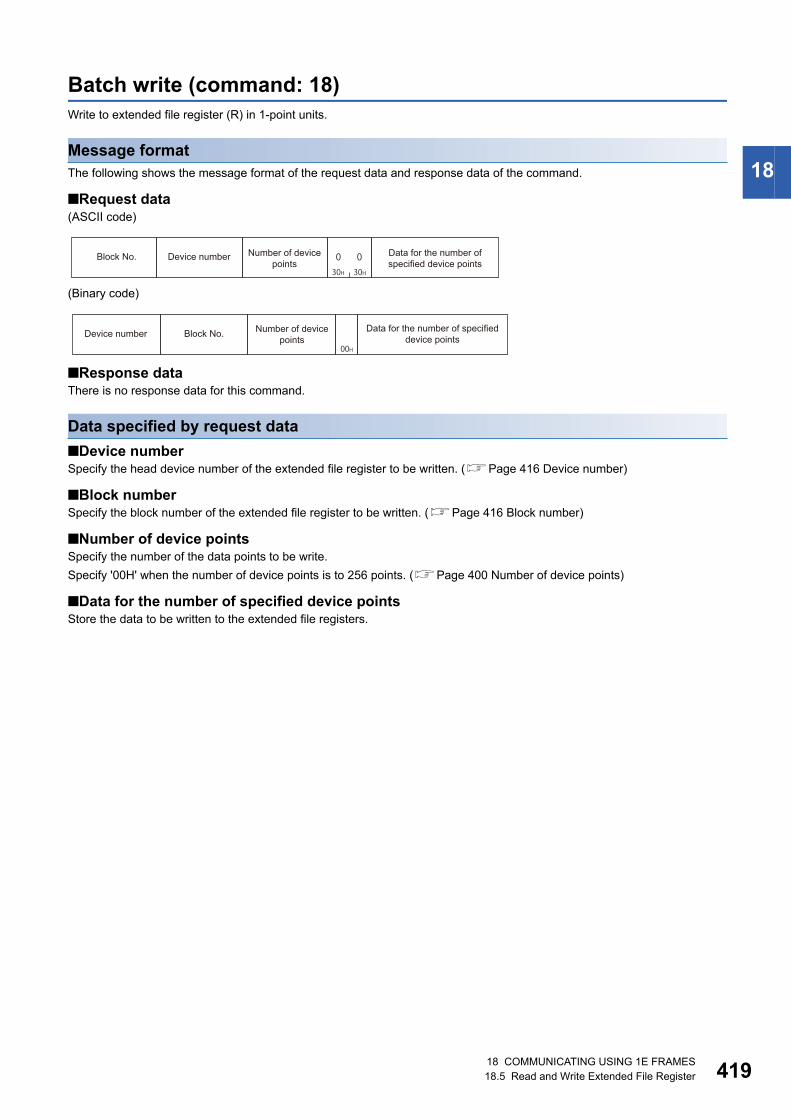
18 COMMUNICATING USING 1E FRAMES18.5 Read and Write Extended File Register 419
18
Batch write (command: 18)Write to extended file register (R) in 1-point units.
Message formatThe following shows the message format of the request data and response data of the command.
■Request data(ASCII code)
(Binary code)
■Response dataThere is no response data for this command.
Data specified by request data
■Device numberSpecify the head device number of the extended file register to be written. (Page 416 Device number)
■Block numberSpecify the block number of the extended file register to be written. (Page 416 Block number)
■Number of device pointsSpecify the number of the data points to be write.
Specify '00H' when the number of device points is to 256 points. (Page 400 Number of device points)
■Data for the number of specified device pointsStore the data to be written to the extended file registers.
30H30H
0 0Block No. Device number Data for the number of specified device points
Number of device points
00H
Device number Block No. Number of device points
Data for the number of specified device points
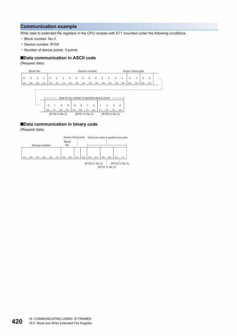
42018 COMMUNICATING USING 1E FRAMES18.5 Read and Write Extended File Register
Communication exampleWrite data to extended file registers in the CPU module with E71 mounted under the following conditions.
• Block number: No.3
• Device number: R100
• Number of device points: 3 points
■Data communication in ASCII code(Request data)
■Data communication in binary code(Request data)
35H 32H 32H 30H 30H 30H 30H 30H 30H 30H 36H 34H 33H30H 30H30H30H30H 33H30H
31H30H 39H30H 38H39H 36H37H 32H31H 34H33H
5 2 2 0 0 0 0 0 0 0 6 4
0 1 0 9 9 8 7 6 1 2 3 4
0 0 0 3 0 3 0 0
Block No. Device number Number of device points
Data for the number of specified device points
(R100 in No.3) (R101 in No.3) (R102 in No.3)
03H 00H64H 00H 00H 00H 20H 52H 03H 00H 09H 01H 76H 98H 34H 12H
Number of device points Data for the number of specified device pointsBlock No.Device number
(R100 in No.3) (R102 in No.3)(R101 in No.3)

18 COMMUNICATING USING 1E FRAMES18.5 Read and Write Extended File Register 421
18
Test (random write) (command: 19)Specify the block numbers and device numbers in 1-point units and write them randomly to extended file register (R).
Message formatThe following shows the message format of the request data and response data of the command.
■Request data(ASCII code)
(Binary code)
■Response dataThere is no response data for this command.
Data specified by request data
■Number of device pointsSpecify the number of points of the data to be written. (Page 400 Number of device points)
■Device numberSpecify the head device of the extended file register to be written. (Page 416 Device number)
■Block numberSpecify the block number of the extended file register to be written. (Page 416 Block number)
■Write dataStore the data to be written to the extended file registers.
30H 30H
0 0
Data for the number of device points
Block No. Device number Write dataNumber of device points
00H
Data for the number of device points
Block No. Write dataNumber of device points Device number

42218 COMMUNICATING USING 1E FRAMES18.5 Read and Write Extended File Register
Communication exampleWrite data to extended file registers in the CPU module with E71 mounted under the following conditions.
• Data to be written: R26 in block number 2 and R19 in block number 3
• Number of device points: 2 points
■Data communication in ASCII code(Request data)
■Data communication in binary code(Request data)
35H 32H 32H 30H 30H 30H 30H 30H 30H 30H 31H 41H32H30H 30H30H 30H30H 32H30H 32H31H 34H33H
35H 32H 32H 30H 30H 30H 30H 30H 30H 30H 31H 33H30H30H 33H30H 31H30H 39H30H
5 2 2 0 0 0 0 0 0 0 1 A20 0 0
30 0 0
41 2 3
90 1 0
2 0 00
5 2 2 0 0 0 0 0 0 0 1 3
Number of device points Block No. Device number Write data
(R26 in block No.2)
Block No. Device number Write data
(R19 in block No.3)
1AH 00H 00H 00H 20H 52H02H 00H 34H 12H02H 00H 13H 00H 00H 00H 20H 52H 09H 01H03H 00H
Block No.
Write data
Block No.
Write data
Number of device points Device number Device number
(R26 in block No.2) (R19 in block No.3)

18 COMMUNICATING USING 1E FRAMES18.5 Read and Write Extended File Register 423
18
Monitor extended file registers (command: 1A, 1B)The contents of extended file registers in the CPU module can be monitored from an external device by registering the block
numbers and device numbers to be monitored to E71 in advance and executing the monitor command from the external
device.
When reading extended file register in batch, the read device numbers will be consecutive. However, when reading them
using the monitor command, the extended file registers can be read randomly by specifying the file registers of arbitrary block
numbers and device numbers.
Procedure for monitoring1. Register block numbers and device numbers of the extended file registers to be monitored to E71 by monitor data
registration.
2. Execute read processing by monitoring.
3. Process the data.
4. If do not change the devices to be monitored, return to step 2, and repeat the process.
• When monitoring data as the procedure shown above, the monitor data registration is required. If monitoring
data without registering the data, an error occurs (END code: 57H).
• The content of registered monitor data is deleted when turning the power OFF or the resetting the CPU
module.
• There are three types of commands for monitor data registration; extended file register, device memory bit
unit, and device memory word unit. The recently registered one command out of three types of commands
can be registered to E71.
• When registering device memory of the CPU module as a monitoring data from more than one external
devices on the same station, the recently registered device memory will be available since the registration
data is overwritten.

42418 COMMUNICATING USING 1E FRAMES18.5 Read and Write Extended File Register
Register monitor data (command: 1A)Register device numbers to be monitored in 1-point units.
■Request data(ASCII code)
(Binary code)
• Number of device points: Specify the number of points of the extended file registers to be registered as a monitor data.
(Page 400 Number of device points)
• Device number: Specify the extended file registers to be registered as a monitor data. (Page 416 Device number)
• Block number: Specify the block number of the extended file registers to be registered as a monitor data. (Page 416
Block number)
■Response dataThere is no response data for this command.
■Communication exampleRegister devices as a monitoring data in the CPU module with E71 mounted under the following conditions.
• Data to be registered: R15 of block number 2 and R28 of block number 3
(Request data)
(ASCII code)
(Binary code)
30H 30H
0 0
Data for the number of device points
Block No.Number of device points
Device number
00H
Data for the number of device points
Device number Block No.Number of device
points
30H 32H 30H 30H 30H 30H 30H 32H 35H 32H 32H 30H 46H30H 30H 30H 30H 30H 30H 30H
30H 30H 30H 33H 35H 32H 32H 30H 30H 30H 30H 30H 30H 30H 31H 43H
5 2 2 0 0 0 0 0 0 0 0 6
5 2 2 0 0 0 0 0 0 0 1 C
20 0 0
30 0 0
20 00
Number of device points Block No. Device number
R15 of block No.2
Device numberBlock No.
R28 of block No.3
02H 00H 0FH 00H 00H 00H 20H 52H 02H 00H 1CH 00H 00H 00H 20H 52H 03H 00H
Number of device points Device number Device numberBlock No. Block No.
(R28 in block No.3)(R15 in block No.2)

18 COMMUNICATING USING 1E FRAMES18.5 Read and Write Extended File Register 425
18
Monitoring (command: 1B)Monitor the extended file registers registered by monitor data registration.
■Data specified by request dataThere is no request data for this command.
■Response dataStore the monitoring result.
■Communication exampleMonitor the following extended file registers registered by monitor data registration.
• Monitor data registration: R15 in block number 2 and R28 in block number 3
(Response data)
(ASCII code)
(Binary code)
45H 35H 36H 44H 31H 32H 33H 34H
E 5 6 D 1 2 3 4
Monitoring result
(R15 in block No.2) (R28 in block No.3)
6DH E5H 34H 12H
Monitoring result
(R15 in block No.2) (R28 in block No.3)

42618 COMMUNICATING USING 1E FRAMES18.5 Read and Write Extended File Register
Direct read (command: 3B)Read extended file register in 1-point (1 word) units by specifying the consecutive device numbers of extended file register.
This command is a dedicated command for AnACPU. (The command is equivalent to AnA/AnUCPU common commands of
1C protocol.)
Message formatThe following shows the message format of the request data and response data of the command.
■Request data
■Response dataThe data for the number of device points are stored.
(Page 400 Read data, write data)
Data specified by request data
■Device numberSpecify the start address of the extended file register to be read. (Page 416 Device number)
■Number of device pointsSpecify the points of extended file register to be read.
Specify '00H' when the number of device points is to 256 points. (Page 400 Number of device points)
■Fixed valueFixed to '0'.
ASCII code Binary code
Number of device points
Fixed valueDevice number
030H
030H 00H

18 COMMUNICATING USING 1E FRAMES18.5 Read and Write Extended File Register 427
18
Communication exampleRead the extended file registers directly in the CPU module with E71 mounted under the following conditions.
• Block number: No.0
• Device number: R70
• Number of device points: 4 points
■Data communication in ASCII code(Request data)
(Response data)
■Data communication in binary code(Request data)
(Response data)
35H 32H 32H 30H 30H 30H 30H 30H 30H 30H 34H 36H 34H30H 30H30H30H30H 32H30H
5 2 2 0 0 0 0 0 0 0 4 620 0 0 0 00 4
Block No. Device number Number of device points
31H 32H 33H 34H 38H 37H 36H 35H 30H 31H 33H 46H 30H 30H 32H 30H
1 2 3 4 8 7 6 5 0 1 3 F 2 00 0
Data for the number of specified device points
(R70 in No.0) (R71 in No.0) (R72 in No.0) (R73 in No.0)
04H 00H46H 00H 00H 00H 20H 52H
Device number Number of device points
12H34H 87H65H 01H3FH 00H20H
Data for the number of specified device points
(R70 in No.0) (R72 in No.0)(R71 in No.0) (R73 in No.0)

42818 COMMUNICATING USING 1E FRAMES18.5 Read and Write Extended File Register
Direct write (command: 3C)Write extended file register in 1-point (1 word) units by specifying the consecutive device number of extended file register.
This command is a dedicated command for AnACPU. (The command is equivalent to AnA/AnUCPU common commands of
1C protocol.)
Message formatThe following shows the message format of the request data and response data of the command.
■Request data
■Response dataThere is no response data for this command.
Data specified by request data
■Device numberSpecify the start address of the extended file register to be written. (Page 416 Device number)
■Number of device pointsSpecify the number of extended file registers to be written. (Page 400 Number of device points)
Specify '00H' when the number of device points is to 256 points.
■Fixed valueFixed to '0'.
■Data for the number of specified device pointsStored data for the number of device points to be written.
ASCII code Binary code
Device number Number of device points
Fixed value
Data for the number of specified device points
030H
030H 00H

18 COMMUNICATING USING 1E FRAMES18.5 Read and Write Extended File Register 429
18
Communication exampleWrite data to the extended file registers directly in the CPU module with E71 mounted under the following conditions.
• Block number: No.0
• Device number: R100
• Number of device points: 3 points
■Data communication in ASCII code(Request data)
■Data communication in binary code(Request data)
35H 32H 32H 30H 30H 30H 30H 30H 30H 30H 36H 34H 33H30H 30H30H 31H30H 39H30H 38H39H 36H37H 32H31H 34H33H5 2 2 0 0 0 0 0 0 0 6 4 0 3 0 0 0 1 0 9 9 8 7 6 1 2 3 4
Data for the number of specified device pointsDevice number Number of device points
(R100 in No.0) (R101 in No.0) (R102 in No.0)
03H 00H64H 00H 00H 00H 20H 52H 09H 01H 76H 98H 34H 12H
Number of device points
Data for the number of specified device pointsDevice number
(R100 in No.0) (R102 in No.0)(R101 in No.0)
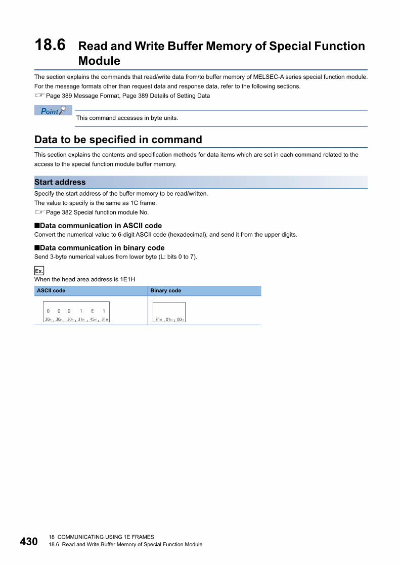
43018 COMMUNICATING USING 1E FRAMES18.6 Read and Write Buffer Memory of Special Function Module
18.6 Read and Write Buffer Memory of Special Function Module
The section explains the commands that read/write data from/to buffer memory of MELSEC-A series special function module.
For the message formats other than request data and response data, refer to the following sections.
Page 389 Message Format, Page 389 Details of Setting Data
This command accesses in byte units.
Data to be specified in commandThis section explains the contents and specification methods for data items which are set in each command related to the
access to the special function module buffer memory.
Start addressSpecify the start address of the buffer memory to be read/written.
The value to specify is the same as 1C frame.
Page 382 Special function module No.
■Data communication in ASCII codeConvert the numerical value to 6-digit ASCII code (hexadecimal), and send it from the upper digits.
■Data communication in binary codeSend 3-byte numerical values from lower byte (L: bits 0 to 7).
Ex.
When the head area address is 1E1H
ASCII code Binary code
0 0 0 1 E 130H 30H 30H 31H 31H45H E1H 01H 00H
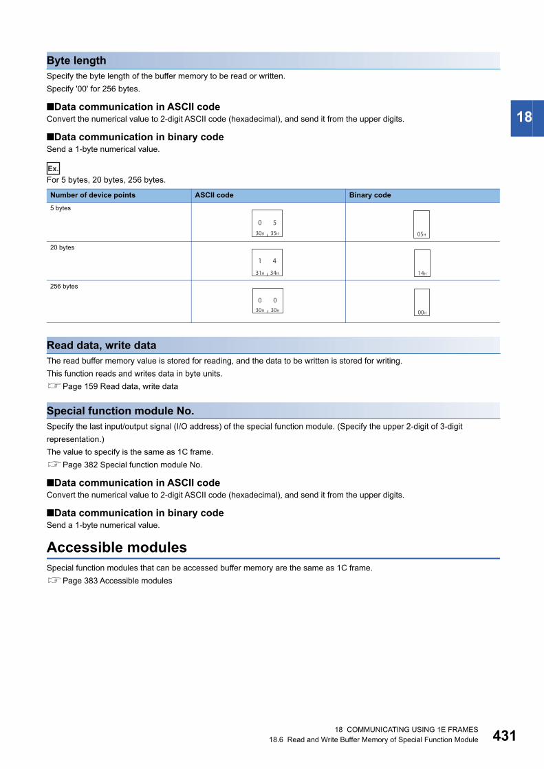
18 COMMUNICATING USING 1E FRAMES18.6 Read and Write Buffer Memory of Special Function Module 431
18
Byte lengthSpecify the byte length of the buffer memory to be read or written.
Specify '00' for 256 bytes.
■Data communication in ASCII codeConvert the numerical value to 2-digit ASCII code (hexadecimal), and send it from the upper digits.
■Data communication in binary codeSend a 1-byte numerical value.
Ex.
For 5 bytes, 20 bytes, 256 bytes.
Read data, write dataThe read buffer memory value is stored for reading, and the data to be written is stored for writing.
This function reads and writes data in byte units.
Page 159 Read data, write data
Special function module No.Specify the last input/output signal (I/O address) of the special function module. (Specify the upper 2-digit of 3-digit
representation.)
The value to specify is the same as 1C frame.
Page 382 Special function module No.
■Data communication in ASCII codeConvert the numerical value to 2-digit ASCII code (hexadecimal), and send it from the upper digits.
■Data communication in binary codeSend a 1-byte numerical value.
Accessible modulesSpecial function modules that can be accessed buffer memory are the same as 1C frame.
Page 383 Accessible modules
Number of device points ASCII code Binary code
5 bytes
20 bytes
256 bytes
30H 35H
0 505H
31H 34H
1 4
14H
30H 30H
0 0
00H

43218 COMMUNICATING USING 1E FRAMES18.6 Read and Write Buffer Memory of Special Function Module
Batch read (command: 0E)Read the buffer memory of a special function module.
Message formatThe following shows the message format of the request data and response data of the command.
■Request data
■Response dataThe data read from buffer memory is stored. (Page 431 Read data, write data)
Data specified by request data
■Start addressSpecify the buffer memory start address to be read. (Page 430 Start address)
■Byte lengthSpecify the byte length of buffer memory to be read.
Specify '00H' when the number of device points is to 256 points. (Page 431 Byte length)
■Special function module No.Specify the special function module No. of the buffer memory to be read.
■Fixed valueFixed to '0'.
ASCII code Binary code
Special function module No.
Start address Byte length Fixed value
030H
030H 00H

18 COMMUNICATING USING 1E FRAMES18.6 Read and Write Buffer Memory of Special Function Module 433
18
Communication exampleRead the buffer memory of the special function module with E71 mounted in the same station under the following conditions.
• Special function module No.: 13H (buffer memory whose input/output signal is from 120H to 13FH)
• Start address: 7F0H
• Byte length: 4
■Data communication in ASCII code(Request data)
(Response data)
■Data communication in binary code(Request data)
(Response data)
30H 30H 30H 37H 46H 30H 30H 34H 31H 33H 30H 30H
0 0 0 7 F 0 0 4 1 3 0 0
Special function module No.Start address Byte length
(7F0H) (7F1H) (7F2H) (7F3H)30H 39H 31H 38H 32H 30H 33H 34H
0 9 1 8 2 0 3 4
Data read
F0H 07H 00H 04H 13H 00H
Byte lengthHead
addressSpecial function module No.
09H 18H 20H 34H
(7F0H)(7F1H) (7F2H)
(7F3H)
Data read

43418 COMMUNICATING USING 1E FRAMES18.6 Read and Write Buffer Memory of Special Function Module
Batch write (command: 0F)Write data to the buffer memory of a special function module.
Message formatThe following shows the message format of the request data and response data of the command.
■Request data
■Response dataThere is no response data for this command.
Data specified by request data
■Start addressSpecify the buffer memory start address to be read. (Page 430 Start address)
■Byte lengthSpecify the byte length of buffer memory to be read.
Specify '00H' when the number of device points is to 256 points. (Page 431 Byte length)
■Special function module No.Specify the special function module No. of the buffer memory to be read.
■Fixed valueFixed to '0'.
■Write dataStore the data to be written in a buffer memory. (Page 431 Read data, write data)
ASCII code Binary code
Special function module No.
Write data(for the length of specified bytes)
Start address Byte length Fixed value
030H
030H 00H

18 COMMUNICATING USING 1E FRAMES18.6 Read and Write Buffer Memory of Special Function Module 435
18
Communication exampleWrite data to buffer the memory of the special function module with E71 mounted in the same station under the following
conditions.
• Special function module No.: 13H (buffer memory whose input/output signal is from 120H to 13FH)
• Start address: 750H
• Byte length: 4
■Data communication in ASCII code(Request data)
■Data communication in binary code(Request data)
30H 30H 30H 37H 35H 30H 30H 34H 31H 33H 30H 30H(750H) (751H) (752H) (753H)
30H 31H 32H 33H 34H 35H 36H 37H
0 0 0 7 5 0 0 4 1 3 0 0 0 1 2 3 4 5 6 7
Special function module No. Write data
Start address Byte length
50H 07H 00H 04H 13H 00H
(750H)(751H) (752H)
(753H)
01H 23H 45H 67H
Byte lengthSpecial function
module No. Write dataStart address

436APPXAppendix 1 Read/Write by Device Extension Specification
APPENDIXAppendix 1 Read/Write by Device Extension
SpecificationAccesses shown below are available by setting the subcommand in a request data to 008 or 00C0.
• Accessing link direct devices
• Accessing module access devices
• Accessing CPU buffer memory access devices
• Accessing by indexing network No. and the start input/output number
• Accessing by indexing the device number
• Accessing by specifying the device number with the value stored in word device with indirect specification
Device specification method for device extension specificationReplace the device portion in a message format of each command with a message format for extension specification
described in this section when the extension is specified.
With commands which can specify more than one device, the devices listed in the following section can be
accessed by specifying '0' for "Extension specification", "Extension specification modification", "Direct
memory specification".
Page 68 Device code list
However, when 008 or 00C0 is specified by "Subcommand", specify the device in the message format
shown in this section. Message formats with extension not specified and message formats with extension
specified cannot coexist in the same message.
ASCII
Device code
When extension is not specified Device numberSubcommandCommand
Number of device points
Indirect specification
Device code
Device modification
When extension is specified
Extension specification
Extension specification modification
Device number
Binary
Subcommand Device code
Number of device points
Device numberCommandWhen extension is not specified
Device modification
Indirect specification
Extension specification modification
Device codeDevice number Extension
specificationWhen extension is specified
Direct memory specification
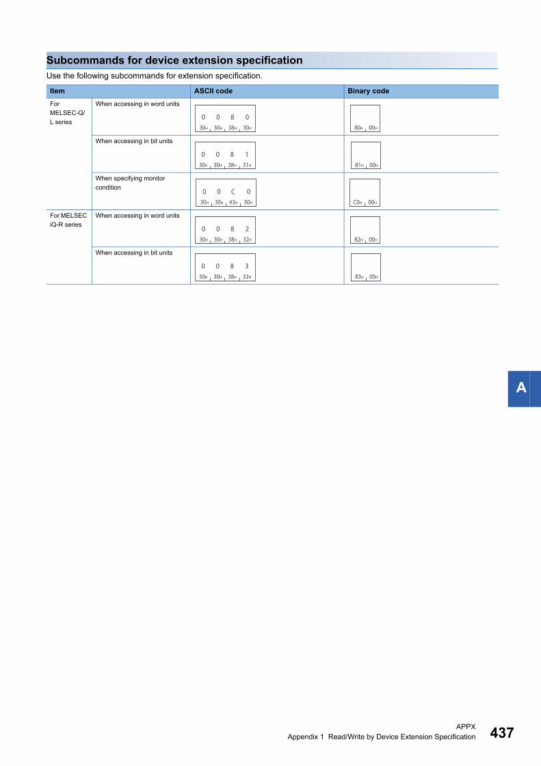
APPXAppendix 1 Read/Write by Device Extension Specification 437
A
Subcommands for device extension specificationUse the following subcommands for extension specification.
Item ASCII code Binary code
For
MELSEC-Q/
L series
When accessing in word units
When accessing in bit units
When specifying monitor
condition
For MELSEC
iQ-R series
When accessing in word units
When accessing in bit units
030H
030H
838H
030H 80H 00H
030H
030H
838H
131H 81H 00H
030H
030H 43H
030H
CC0H 00H
030H
030H
838H
232H 82H 00H
030H
030H
838H
333H 83H 00H

438APPXAppendix 1 Read/Write by Device Extension Specification
Accessing link direct devicesAccess link devices of the network modules such as remote input (RX), remote output (RY), and link special relay (SB).
The following device access commands can be used for access.
Message format for device extension specification
■Data communication in ASCII code
■Data communication in binary code
Function Command Subcommand
Batch read 0401 0080, 0081, 0082, 0083
Batch write 1401 0080, 0081, 0082, 0083
Random read 0403 0080, 0082, 00C0
Random write 1402 0080, 0081, 0082, 0083
Batch read multiple blocks 0406 0080, 0082
Batch write multiple blocks 1406 0080, 0082
Register monitor data 0801 0080, 0082, 00C0
Subcommand type ASCII code
For MELSEC-Q/L series
For MELSEC iQ-R series
Subcommand type Binary code
For MELSEC-Q/L series
For MELSEC iQ-R series
JExtension
specificationDevice code
Device number
\
0 030H 30H
0 030H 30H
030H
0 030H 30H
030H
J4AH
Device numberDevice code
Extension specification
(2 digits) (6 digits)(3 digits)
0 030H 30H
030H
030H
030H
030H
030H
030H
030H
030H
J4AH
Extension specification Device code Device number
(4 digits) (10 digits)
00H 00H F9H00H 00H
Device codeDevice number
Extension specification
(3 bytes) (1 byte)
00H 00H F9H00H 00H
Device codeDevice number
Extension specification
(4 bytes) (2 bytes)
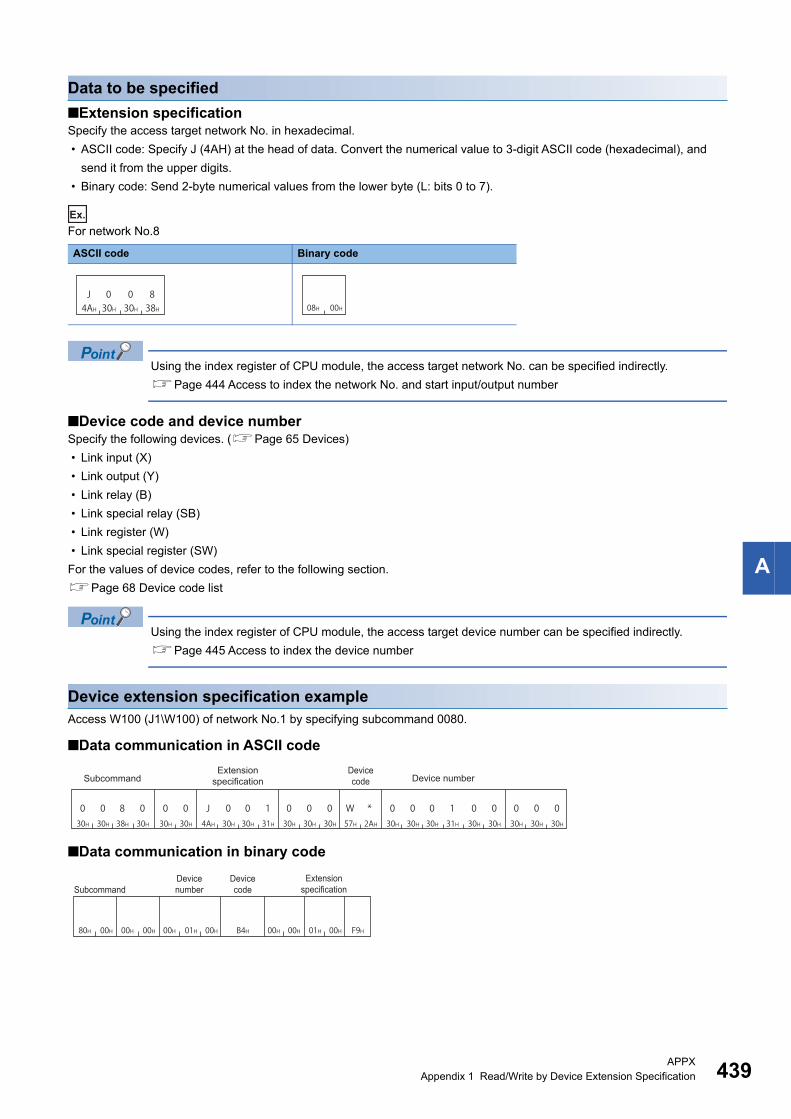
APPXAppendix 1 Read/Write by Device Extension Specification 439
A
Data to be specified
■Extension specificationSpecify the access target network No. in hexadecimal.
• ASCII code: Specify J (4AH) at the head of data. Convert the numerical value to 3-digit ASCII code (hexadecimal), and
send it from the upper digits.
• Binary code: Send 2-byte numerical values from the lower byte (L: bits 0 to 7).
Ex.
For network No.8
Using the index register of CPU module, the access target network No. can be specified indirectly.
Page 444 Access to index the network No. and start input/output number
■Device code and device numberSpecify the following devices. (Page 65 Devices)
• Link input (X)
• Link output (Y)
• Link relay (B)
• Link special relay (SB)
• Link register (W)
• Link special register (SW)
For the values of device codes, refer to the following section.
Page 68 Device code list
Using the index register of CPU module, the access target device number can be specified indirectly.
Page 445 Access to index the device number
Device extension specification exampleAccess W100 (J1\W100) of network No.1 by specifying subcommand 0080.
■Data communication in ASCII code
■Data communication in binary code
ASCII code Binary code
J4AH
030H
030H
838H 08H 00H
0 030H 30H
0 030H 30H
8 038H 30H
0 030H 30H
0 130H 31H
0 030H 30H
J 04AH 30H
0 130H 31H
0 030H 30H
030H
W57H
*2AH
0 030H 30H
030H
Device code Device numberSubcommand
Extension specification
00H 00H 00H 01H 00H B4H F9H00H 00H 01H 00H80H 00H
SubcommandDevice number
Device code
Extension specification

440APPXAppendix 1 Read/Write by Device Extension Specification
Accessing module access devicesAccess buffer memory of an intelligent function module.
The following device access commands can be used for access.
Message format for device extension specification
■Data communication in ASCII code
■Data communication in binary code
Function Command Subcommand
Batch read 0401 0080, 0082
Batch write 1401 0080, 0082
Random read 0403 0080, 0082, 00C0
Random write 1402 0080, 0082
Batch read multiple blocks 0406 0080, 0082
Batch write multiple blocks 1406 0080, 0082
Register monitor data 0801 0080, 0082, 00C0
Subcommand type ASCII code
For MELSEC-Q/L series
For MELSEC iQ-R series
Subcommand type Binary code
For MELSEC-Q/L series
For MELSEC iQ-R series
U GExtension
specificationDevice code
Device number
\
0 030H 30H
0 030H 30H
030H
0 030H 30H
030H
U55H
Device code
Extension specification Device number
(2 digits) (6 digits)
0 030H 30H
030H
030H
030H
030H
030H
030H
030H
030H
U55H
Extension specification Device code Device number
(4 digits) (10 digits)
00H 00H F8H00H 00H
Device codeDevice number
Extension specification
(3 bytes) (1 byte)
00H 00H F8H00H 00H
Device codeDevice number Extension specification
(4 bytes) (2 bytes)

APPXAppendix 1 Read/Write by Device Extension Specification 441
A
Data to be specified
■Extension specificationSpecify the value obtained by dividing the start input/output number of an intelligent function module by 16 in hexadecimal.
• ASCII code: Specify U (55H) at the head of data. Convert the numerical value to 3-digit ASCII code (hexadecimal), and
send it from the upper digits.
• Binary code: Send 2-byte numerical values from the lower byte (L: bits 0 to 7).
Ex.
Start input/output number 0010H of a module
Indirect specification of the start input/output number can also be performed by using the CPU module index
register.
Page 444 Access to index the network No. and start input/output number
■Device code and device numberSpecify the following device. (Page 65 Devices)
• Module access device (G)
For the values of device codes, refer to the following section.
Page 68 Device code list
Using the index register of CPU module, the access target device number can be specified indirectly.
Page 445 Access to index the device number
Device extension specification exampleAccess the buffer memory (address: 1) of intelligent function module whose start input/output number is 0030H by specifying
subcommand 0080.
■Data communication in ASCII code
■Data communication in binary code
ASCII code Binary code
55H 30H 30H 31HU 0 0 1
01H 00H
0 030H 30H
0 030H 30H
8 038H 30H
U 055H 30H
0 330H 33H
0 030H 30H
0 030H 30H
0 130H 31H
0 030H 30H
030H
G47H
*2AH
0 030H 30H
030H
Device codeSubcommand
Extension specification Device number
00H 00H 01H 00H 00H80H 00H F8H00HABH 00H 03H 00H
SubcommandDevice codeDevice number
Extension specification

442APPXAppendix 1 Read/Write by Device Extension Specification
Accessing CPU buffer memory access deviceAccess the buffer memory of RCPU.
The following device access commands can be used for access.
Message format for device extension specification
■Data communication in ASCII code
■Data communication in binary code
Function Command Subcommand
Batch read 0401 0082
Batch write 1401 0082
Random read 0403 0082
Random write 1402 0082
Batch read multiple blocks 0406 0082
Batch write multiple blocks 1406 0082
Register monitor data 0801 0082
Subcommand type ASCII code
For MELSEC iQ-R series
Subcommand type Binary code
For MELSEC iQ-R series
UDevice numberExtension
ifi tiDevice code
\
0 030H 30H
0
30H
0
30H
0
30H
0
30H030H
030H
030H
030H
U55H
333H
E45H
Extension specification Device code Device number
(4 digits) (10 digits)
00H 00H FAH00H 00H
Device codeDevice number
Extension specification
(4 bytes) (2 bytes)

APPXAppendix 1 Read/Write by Device Extension Specification 443
A
Data to be specified
■Extension specificationSpecify the start input/output number of CPU module with the upper 3 digits of 4-digit in hexadecimal.
• ASCII code: Specify U (55H) at the head of data. Convert the numerical value to 3-digit ASCII code (hexadecimal), and
send it from the upper digits.
• Binary code: Send 2-byte numerical values from the lower byte (L: bits 0 to 7).
The start input/output numbers of CPU modules to be specified are as shown below.
Ex.
For CPU No.4 (start input/output number: 3E30H)
Indirect specification of the start input/output number of the CPU module can also be performed by using the
CPU module index register.
Page 444 Access to index the network No. and start input/output number
■Device code and device numberSpecify the following devices. (Page 65 Devices)
• CPU buffer memory access device (G)
• CPU buffer memory access device (HG)
For the values of device codes, refer to the following section.
Page 68 Device code list
Using the index register of CPU module, the access target device number can be specified indirectly.
Page 445 Access to index the device number
Device extension specification exampleAccess the buffer memory (address: 1) of the CPU No.1 (start input/output number: 03E0H) by specifying the subcommand
0082.
■Data communication in ASCII code
■Data communication in binary code
CPU number Start input/output number of CPU module Value to be specified
CPU No.1 3E00H 3E0H
CPU No.2 3E10H 3E1H
CPU No.3 3E20H 3E2H
CPU No.4 3E30H 3E3H
ASCII code Binary code
U55H
333H
E45H
333H E3H 03H
0 030H 30H 55H 33H 45E 30H 30H 30H 30H 30H 47H 2AH 2AH 2AH 30H
0 030H 30H
8 238H 32H
U 3 0 0E 0 0 0 0 0 0 0 0 0 1 0 0 0 030H 30H 30H 30H
0 0 0 G * * *30H 30H 31H 30H30H 30H 30H30H30H
Device codeSubcommand
Extension specification Device number
82H 00H 00H 00H 01H 00H 00H 00H ABH 00H 00H 00H E0H 03H FAH
SubcommandDevice codeDevice number
Extension specification

444APPXAppendix 1 Read/Write by Device Extension Specification
Access for index modificationIndex modification is the indirect specification using index registers.
Accesses shown below are available by setting the subcommand in a request data to 008 or 00C0.
The following device access commands can be used for access.
Access to index the network No. and start input/output numberWhen accessing a link direct device, the access target network No. can be specified by the index register with indirect
specification. Also, when accessing a module access device or a CPU buffer memory access device, the access target start
input/output number can be specified by the index register with indirect specification.
The access target can be switched with one message, by changing the value of the index register in CPU module programs.
Ex.
The access target can be switched by changing the value of 'Z0', when multiple network modules are mounted onto the
access target.
Target data Reference
Network No. or start input/output number Page 444 Access to index the network No. and start input/output number
Device number Page 445 Access to index the device number
Function Command Subcommand
Random read 0403 0080, 0082, 00C0
Random write 1402 0080, 0081, 0082, 0083
Register monitor data 0801 0080, 0082, 00C0
UJ
Z Z
\ \
Extension specification,Direct memory specification
Device code Device number
Extension specification modification
+
Extension specification,Direct memory specification
Device code Device number
Extension specification modification
+
0
Z0
SW0
SW5
SW0
SW5
SW0
SW5
Specify this in request data.
Network number(offset value)
1 to 3 Network number to access
Specify this on the program of the CPU module.
Module onnetwork number 1
Module on network number 2
Module on network number 3
Specify access destinationdevice in request data.(Access destination) (Access destination) (Access destination)
By changing the "Z0" value, the access destination can be changed.
=+
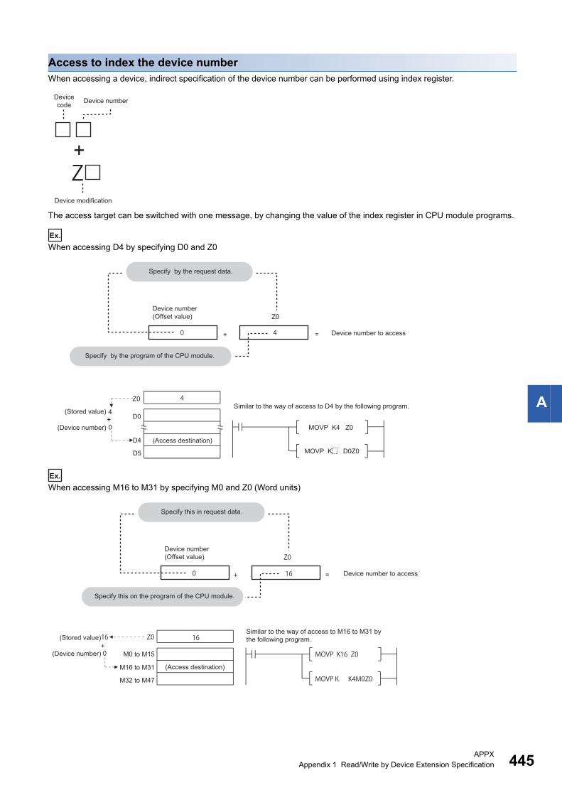
APPXAppendix 1 Read/Write by Device Extension Specification 445
A
Access to index the device numberWhen accessing a device, indirect specification of the device number can be performed using index register.
The access target can be switched with one message, by changing the value of the index register in CPU module programs.
Ex.
When accessing D4 by specifying D0 and Z0
Ex.
When accessing M16 to M31 by specifying M0 and Z0 (Word units)
Z
Device code Device number
Device modification
+
4
0 4
Specify by the request data.
Device number(Offset value) Z0
Device number to access=+
Specify by the program of the CPU module.
Z0Similar to the way of access to D4 by the following program.
(Stored value) 4D0++
0 MOVP K4 Z0(Device number)
D4 (Access destination)MOVP K D0Z0D5
16
0 16
Z0
Z0
MOVP K16 Z0
MOVP K K4M0Z0
16
0
Specify this in request data.
Device number to access=+
Specify this on the program of the CPU module.
Similar to the way of access to M16 to M31 bythe following program.(Stored value)
+(Device number) M0 to M15
(Access destination)M16 to M31
M32 to M47
Device number(Offset value)

446APPXAppendix 1 Read/Write by Device Extension Specification
Message format for device extension specification
■Data communication in ASCII code
■Data communication in binary code
The following shows the correspondence of each data.
Data to be specified
■Extension specification, device code, and device numberSpecify the access target network No. and the offset value of the start input/output number for extension specification.
When indexing a network No. and start input/output number by "Extension specification modification", the values specified by
"Extension specification" will be the offset value.
When indexing a device number by "Device modification", the values specified by "Device number" will be the offset value.
For the data to be specified for each access device, refer to the following table.
■Direct memory specification (only when communicating in binary code)Specify the type of access device.
Specify '0' when accessing devices other than link direct device, module access device, and CPU buffer memory access
device.
Item Reference
Link direct device Page 439 Data to be specified
Module access device Page 441 Data to be specified
CPU buffer memory access device Page 443 Data to be specified
Item Value to be specified
Link direct device F9H
Module access device F8H
CPU buffer memory access device FAH
Binary code
Specify '0'.
0 030H 30H
Extension specification modification
Device code
Device modification
Extension specification Device number
00H 00H
Device code
Extension specification modification
Direct memory
specificationDevice number Extension
specification
J UZ Z
XZZ Z
Extension specification,Direct memory specification
Device code
Extension specification,Direct memory specification
Device code
Device codeDevice number Device number Device number
Extension specification modification
Device modification
Device modification
Extension specification modification
Device modification
\ \+ + ++ +
00H 00H
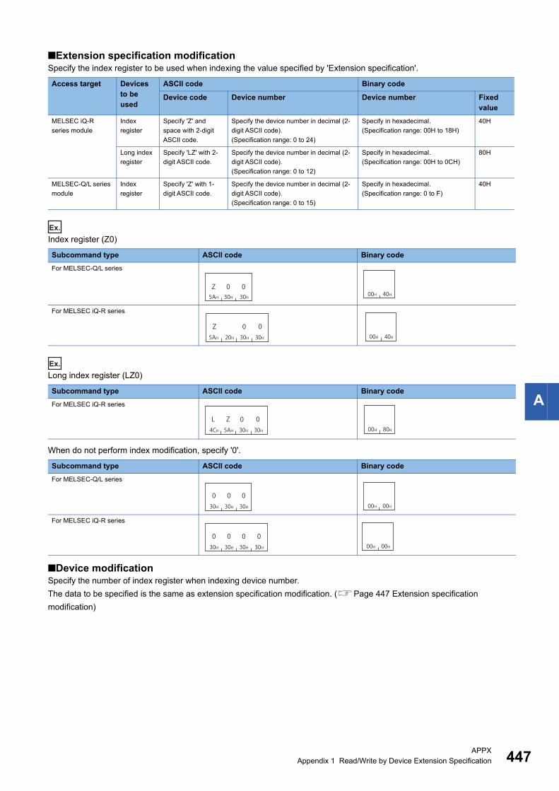
APPXAppendix 1 Read/Write by Device Extension Specification 447
A
■Extension specification modificationSpecify the index register to be used when indexing the value specified by 'Extension specification'.
Ex.
Index register (Z0)
Ex.
Long index register (LZ0)
When do not perform index modification, specify '0'.
■Device modificationSpecify the number of index register when indexing device number.
The data to be specified is the same as extension specification modification. (Page 447 Extension specification
modification)
Access target Devices to be used
ASCII code Binary code
Device code Device number Device number Fixed value
MELSEC iQ-R
series module
Index
register
Specify 'Z' and
space with 2-digit
ASCII code.
Specify the device number in decimal (2-
digit ASCII code).
(Specification range: 0 to 24)
Specify in hexadecimal.
(Specification range: 00H to 18H)
40H
Long index
register
Specify 'LZ' with 2-
digit ASCII code.
Specify the device number in decimal (2-
digit ASCII code).
(Specification range: 0 to 12)
Specify in hexadecimal.
(Specification range: 00H to 0CH)
80H
MELSEC-Q/L series
module
Index
register
Specify 'Z' with 1-
digit ASCII code.
Specify the device number in decimal (2-
digit ASCII code).
(Specification range: 0 to 15)
Specify in hexadecimal.
(Specification range: 0 to F)
40H
Subcommand type ASCII code Binary code
For MELSEC-Q/L series
For MELSEC iQ-R series
Subcommand type ASCII code Binary code
For MELSEC iQ-R series
Subcommand type ASCII code Binary code
For MELSEC-Q/L series
For MELSEC iQ-R series
5AH 30H 30HZ 0 0
00H 40H
Z5AH 20H 30H
030H
000H 40H
Z5AH4CH 30H
030H
0L00H 80H
030H
030H 30H
000H 00H
030H
030H
030H
030H 00H 00H

448APPXAppendix 1 Read/Write by Device Extension Specification
Communication example (indexing network No.)Access W100 (J1Z0\W100) of network No.1 + Z0 by specifying subcommand 0080.
■Data communication in ASCII code
■Data communication in binary code
Device extension specification example (When indexing the device number)Access D100Z4 by specifying subcommand 0080.
■Data communication in ASCII code
■Data communication in binary code
0 030H 30H
8 038H 30H
J 04AH 30H
0 130H 31H
0 030H 30H
0 130H 31H
0 030H 30H
Z5AH
0 030H 30H
W *57H 2AH
0 030H 30H
0 030H 30H
030H
Device codeSubcommand
Extension specification
Extension specification modification Device number
00H 00H 00H 40H 01H 00H00H 01H 00H B4H F9H80H 00H
Subcommand
Device number
Device code
Extension specification modification
Direct memory specification
Extension specification
0 030H 30H
D *44H 2AH
0 030H 30H
0 030H 30H
8 038H 30H
0 030H 30H
0 030H 30H
030H
0 030H 30H
Z5AH
0 430H 34H
0 030H 30H
0 130H 31H
Device numberDevice codeSubcommand
Extension specification
Extension specification modification
Device modification
80H 00H 04H 40H 64H 00H 00H A8H 00H 00H 00H 00H 00H
Device numberSubcom
mandDevice
modificationDevice code
Extension specification modification
Extension specification
Direct memory specification

APPXAppendix 1 Read/Write by Device Extension Specification 449
A
Accessing devices for indirect specificationAccess the device corresponding to the address stored in the word device (2 points).
Store the address of the access target device in the device for the indirect specification, and represent the data as '@ + device
for indirect specification'.
For details on the indirect specification, refer to the following manual.
MELSEC iQ-R CPU Module User's Manual (Application)
The following device access commands can be used for access.
Message format for device extension specification
■Data communication in ASCII code
■Data communication in binary code
Function Command Subcommand
Random read 0403 0080, 0082, 00C0
Random write 1402 0080, 0082
Register monitor data 0801 0080, 0082, 00C0
Subcommand type ASCII code
For MELSEC-Q/L series
For MELSEC iQ-R series
Subcommand type Binary code
For MELSEC-Q/L series
For MELSEC iQ-R series
Z
Device code
Indirect specification Device number
Device modification
+@
0 030H 30H
030H
0 030H 30H
030H
030H 40H
030H
Device code
Device modificationDevice number@
030H 40H
030H
030H
030H
030H
030H
030H
030H
030H
Device code Device number Device modification@
00H 00HH 8H 00H 00H 00H
Device code
Device number
Indirect specificationDevice modification
H 8H 00H00H 00H 00H 00H
Device codeDevice number
Indirect specificationDevice modification

450APPXAppendix 1 Read/Write by Device Extension Specification
Data to be specified
■Device code and device numberSpecify the devices for indirect specification. (Page 65 Devices)
Indirect specification can be used only for word devices.
When indexing a device number by "Device modification", the values specified by "Device number" will be the offset value.
For the values of device codes, refer to the following section.
Page 68 Device code list
■Device modificationSpecify the number of index register when the device number is indirectly specified with index register.
Ex.
Index register (Z0)
Ex.
For long index register (LZ0)
When do not perform index modification, specify the following.
Access target Devices to be used
ASCII code Binary code
Device code Device number Device number Fixed value
MELSEC iQ-R
series module
Index
register
Specify 'Z' and
space with 2-digit
ASCII code.
Specify the device number in decimal (2-
digit ASCII code).
(Specification range: 0 to 24)
Specify in hexadecimal.
(Specification range: 00H to 18H)
48H
Long index
register
Specify 'LZ' with 2-
digit ASCII code.
Specify the device number in decimal (2-
digit ASCII code).
(Specification range: 0 to 12)
Specify in hexadecimal.
(Specification range: 00H to 0CH)
88H
MELSEC-Q/L series
module
Index
register
Specify 'Z' with 1-
digit ASCII code.
Specify the device number in decimal (2-
digit ASCII code).
(Specification range: 0 to 15)
Specify in hexadecimal.
(Specification range: 0 to F)
48H
Subcommand type ASCII code Binary code
For MELSEC-Q/L series
For MELSEC iQ-R series
Subcommand type ASCII code Binary code
For MELSEC iQ-R series
Subcommand type ASCII code Binary code
For MELSEC-Q/L series
For MELSEC iQ-R series
5AH 30H 30HZ 0 0
00H 48H
Z5AH 20H 30H
030H
000H 48H
Z5AH4CH 30H
030H
0L00H 88H
030H
030H 30H
000H 08H
030H
030H
030H
030H 00H 08H

APPXAppendix 1 Read/Write by Device Extension Specification 451
A
Device extension specification example (when do not perform index modification)Access D100 by specifying the subcommand 0080 and using devices for indirect specification '@D0'.
Store the address of D100 in D0 with a program before executing the command.
■Data communication in ASCII code
■Data communication in binary code
Device extension specification example (Index modification)Access D100 by specifying subcommand 0080 and specify the index modified device for indirect specification @D0Z2.
Before executing the command, store the D100 address in D4 and '4' in Z2 with the program.
■Data communication in ASCII code
■Data communication in binary code
ADRSET D100 D0
D0
D100
D1
Specify by the request data. Specify by the program of the CPU module.
(Device number) Address of the access destination (D100) can be stored to D0 and D1 by the following program.
(Access destination)
The address of the access destination
(D100)
030H
030H
030H
030H
030H
030H
030H
030H
030H
030H
030H
030H
030H
030H
030H
030H 40H
838H
030H
030H
030H
030H
D44H
*2AH
Device code Device number
Indirect specificationSubcommand
Device modification
@
00HA8H 00H80H 00H 00H 08H 00H 00H 00H 00H 00H 00H
Device modificationIndirect specificationSubcommand
Device code
Device number
4
0 4
4
0
ADRSET D100 D4
MOVP K4 Z2
Z2
D0
D4D5
Z2
D100
Specify by the request data.
Device number(Offset value)
Device number for extension specification
Specify by the program of the CPU module.
Store Z2 to 4 by the following program.(Stored value)
(Device number)
The address of the access destination
(D100)
Address of the access destination (D100) can be stored to D4 and D5 by the following program.
(Access destination)
+
+ =
030H
030H
030H
030H
030H
030H
030H
030H
030H
030H
Z5AH
030H
232H
030H
030H
030H 40H
838H
030H
030H
030H
030H
D44H
*2AH
Device code Device number
Indirect specificationSubcommand
Device modification
@
00HA8H 00H80H 00H 02H 48H 00H 00H 00H 00H 00H 00H
Device modificationIndirect specificationSubcommand
Device code
Device number

452APPXAppendix 2 Processing Time
Appendix 2 Processing Time
Time chart and communication time of C24 transmission sequenceThe following figure shows a communication time chart when accessing programmable controller from an external device via
C24.
When accessing CPU module with C24 mounted from an external deviceThe following shows the time chart when the message wait time is specified.
For the number of scans required for processing a read/write request, refer to the following section.
Page 457 Number of scans required for processing
For the number of points processed per communication, refer to the following section.
Page 464 Number of Processing per One Communication
■Reading data
■Writing data
• The communication between C24 and CPU module is always performed after END. Therefore, the scan
time becomes longer according to the communication time (the time to interrupt to the CPU module).
• The number of scans required for processing to request read/write operation to the CPU module differs
depending on the content of the request. For example, when a read operation that requires a scan is
requested, it takes an extra time of 1 scan + T2.
• The number of scans required for the processing varies depending on the Service Processing Setting. It can
be set in the parameter settings of Engineering tool. For details of Service Processing Setting, refer to the
user's manual of the CPU module used.
T0
ENQ
STX
END 0 END 0 END 0 END 0 END
T1 T2
T4
C24
External deviceMessage wait time (TW)
Read
tra
nsmiss
ion
CPU module
Program
T0
ENQ
ACK
END 0 END 0 END 0 END 0 END
T1 T2
T4
C24
T3T5
External deviceMessage wait time (TW)
Checking the RUN/STOP of the CPU
Write
transm
ission
Write
transm
ission
Writing data
CPU module
Program

APPXAppendix 2 Processing Time 453
A
Transmission time of transmission sequenceThe following explains the approximate time required from when external device starts data transmission to when C24 returns
the result.
The average of the above approximate time is shown below for the estimation of the processing time.
■When external device reads data from a programmable controller (unit: ms)
■When external device writes data to a programmable controller
Communication time = Request message transmission time (T0) + [(T1 + (1.5 × scan time) + T2) or TW] + Response message transmission time (T4)
(When the value exceeds TW)
Communication time = Request message transmission time (T0) + [(T1 + (1.5 × scan time) + T2 + T3 + T5) or TW] + Response message transmission time (T4)
(When the value exceeds TW)
T0, T4 = × number of bits for 1 byte at transmission ( 1 + 7/8 + 0/1 + 1/2 ) × number of bytes
Stop bit(1 or 2)Start bit
Parity bit(0 or 1)
Data length(7 or 8)
T1 = C24 processing timeDepending on the access points (MIN to MAX), the following ranges.
RJ71C24(-R2/-R4)QJ71C24N(-R2/-R4), LJ71C24(-R2)QJ71C24(-R2)
: 12.0 to 45.0 ms: 12.5 to 45.0 ms: 13.0 to 70.0 ms
T2, T3 = CPU intervention timeT5 = Scan time (For functions that can process one scan, T3 and T5 equal 0.)TW = The set time when message wait time is set.
1000Transmission rate
: 0.07 to 13.1ms
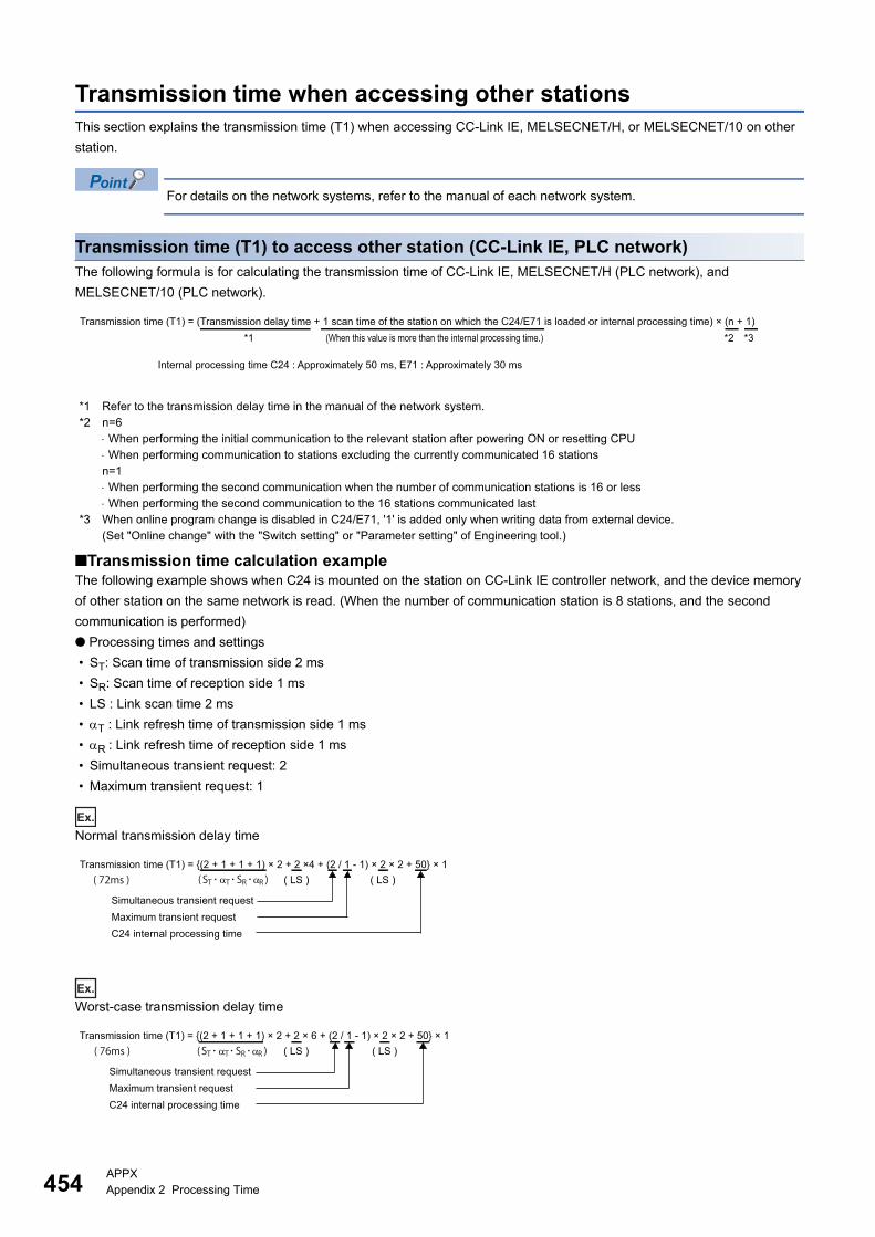
454APPXAppendix 2 Processing Time
Transmission time when accessing other stationsThis section explains the transmission time (T1) when accessing CC-Link IE, MELSECNET/H, or MELSECNET/10 on other
station.
For details on the network systems, refer to the manual of each network system.
Transmission time (T1) to access other station (CC-Link IE, PLC network)The following formula is for calculating the transmission time of CC-Link IE, MELSECNET/H (PLC network), and
MELSECNET/10 (PLC network).
*1 Refer to the transmission delay time in the manual of the network system.*2 n=6
When performing the initial communication to the relevant station after powering ON or resetting CPU When performing communication to stations excluding the currently communicated 16 stationsn=1 When performing the second communication when the number of communication stations is 16 or less When performing the second communication to the 16 stations communicated last
*3 When online program change is disabled in C24/E71, '1' is added only when writing data from external device.(Set "Online change" with the "Switch setting" or "Parameter setting" of Engineering tool.)
■Transmission time calculation exampleThe following example shows when C24 is mounted on the station on CC-Link IE controller network, and the device memory
of other station on the same network is read. (When the number of communication station is 8 stations, and the second
communication is performed)
● Processing times and settings
• ST: Scan time of transmission side 2 ms
• SR: Scan time of reception side 1 ms
• LS : Link scan time 2 ms
• T : Link refresh time of transmission side 1 ms
• R : Link refresh time of reception side 1 ms
• Simultaneous transient request: 2
• Maximum transient request: 1
Ex.
Normal transmission delay time
Ex.
Worst-case transmission delay time
Transmission time (T1) = (Transmission delay time + 1 scan time of the station on which the C24/E71 is loaded or internal processing time) × (n + 1)(When this value is more than the internal processing time.)
Internal processing time C24 : Approximately 50 ms, E71 : Approximately 30 ms
*1 *2 *3
( 72ms )Transmission time (T1) = {(2 + 1 + 1 + 1) × 2 + 2 ×4 + (2 / 1 - 1) × 2 × 2 + 50} × 1
Simultaneous transient requestMaximum transient requestC24 internal processing time
( LS ) ( LS )
( 76ms )Transmission time (T1) = {(2 + 1 + 1 + 1) × 2 + 2 × 6 + (2 / 1 - 1) × 2 × 2 + 50} × 1
Simultaneous transient requestMaximum transient requestC24 internal processing time
( LS ) ( LS )

APPXAppendix 2 Processing Time 455
A
■Causes of transmission time (T1) delayWhen a command that takes two scans to send is executed, the transmission time is twice the value obtained by the formula
above .
When the access request is issued to the same station from multiple external devices simultaneously, refer to the precautions
for data communication. (Page 23 When accessing CPU module)
Data transmission to the CPU module other than connected station (host station) on CC-Link IE,
MELSECNET/H, or MELSECNET/10 may be delayed considerably depending on conditions. The
transmission delay time can be shortened by limiting communication between an external device and the CPU
module to the station with C24/E71 mounted, and communicating with programmable controllers on other
stations by data link (LB, LW).
Transmission time (T1) to access other station (remote I/O net)The following shows the transmission time for MELSECNET/H(remote I/O net) and MELSECNET/10(remote I/O net).
MELSEC iQ-R series and MELSEC-L series are not supported.
*1 Refer to the transmission delay time in the reference manual (remote I/O network) of the network system.*2 n=6
When performing the initial communication to the relevant station after starting link. When communicating with stations other than the latest 16 stations communicated with.n=1 When performing the second communication when the number of communication stations is 16 or less When performing the second communication to the 16 stations communicated last
*3 When online program change is disabled in C24/E71, '1' is added only when writing data from external device.(Set the parameter in the Switch Setting for C24. As for E71, set it in Operation Settings using Engineering tool.)
■Transmission time calculation exampleThe following example shows when C24 is mounted on the station on MELSECNET/H (remote I/O net), and the device
memory of other station on the same network is read. (When the number of communication station is 8 stations, and the
second communication is performed)
● Processing times
• Sm: Scan time of remote master station sequence program 12 ms
• m: Link refresh time of remote master station 5 ms
• LS : Link scan time 9 ms
Since the processing time is (Sm) > (LS), the transmission time (T1) will be as follows:
Ex.
When master station is one station
Transmission time (T1) = (Transmission delay time + 1 link scan time or internal processing time) × (n + 1)
(When this value is more than the internal processing time.)
Internal processing time C24 : Approximately 50 ms, E71 : Approximately 30 ms
*1 *2 *3
( 101ms )Transmission time (T1) = {(12 + 5) × 3 + 50} × 1

456APPXAppendix 2 Processing Time
■Causes of transmission time (T1) delayWhen a command that takes two scans to send is executed, the transmission time is twice the value obtained by the formula
above .
When the access request is issued to the same station from multiple external devices simultaneously, refer to the precautions
for data communication. (Page 23 When accessing CPU module)
Data transmission to the CPU module other than connected station (host station) on MELSECNET/H may be
delayed considerably depending on conditions. The transmission delay time can be shortened by limiting
communication between an external device and the CPU module to the station with C24/E71 mounted, and
communicating with programmable controllers on other stations by data link (LB, LW).

APPXAppendix 2 Processing Time 457
A
Number of scans required for processing
When connected to C24/E71
■Basic model QCPU
■High performance model QCPU
Function Command Subcommand Number of scans required for processing
Online change is enabled
Online change is disabled
Device access Batch read and write Batch read in word units 0401 0000 1 1
Batch read in bit units 0001 1 1
Batch write in word units 1401 0000 1 2
Batch write in bit units 0001 1 2
Random read and write Random read in word units 0403 0000 1 1
Random write in word units (test) 1402 0000 1 2
Random write in bit units (test) 0001 1 2
Batch read and write
multiple blocks
Batch read multiple blocks 0406 0000 1 1
Batch write multiple blocks 1406 0000 1 2
Monitor device memory Register monitor data 0801 0000 0 0
Monitor 0802 0000 1 1
Buffer memory
access
Intelligent function
module
Batch read 0601 0000 1 1
Batch write 1601 0000 1 2
Module control Remote control Read CPU model name 0101 0000 1 1
Function Command Subcommand Number of scans required for processing
Online change is enabled
Online change is disabled
Device access Batch read and write Batch read in word units 0401 0000 1 1
Batch read in bit units 0001 1 1
Batch write in word units 1401 0000 1 2
Batch write in bit units 0001 1 2
Random read and write Random read in word units 0403 0000 1 1
Random write in word units (test) 1402 0000 1 2
Random write in bit units (test) 0001 1 2
Batch read and write
multiple blocks
Batch read multiple blocks 0406 0000 1 1
Batch write multiple blocks 1406 0000 1 2
Monitor device memory Register monitor data 0801 0000 0 0
Monitor 0802 0000 1 1
Buffer memory
access
Intelligent function
module
Batch read 0601 0000 0 0
Batch write 1601 0000 0 1
Module control Remote control Read CPU model name 0101 0000 0 0

458APPXAppendix 2 Processing Time
■Universal model QCPU, LCPU, RCPU
File control File check Read directory/file information 1810 0000 0 0
Search directory/file information 1811 0000 0 0
File creation and deletion Create new file 1820 0000 1 2
Delete file 1822 0000 0 1
Copy file 1824 0000 1 2
File modification Modify file attribute 1825 0000 0 1
Modify file creation date and time 1826 0000 0 1
Open file 1827 0000 0 0
Read file 1828 0000 1 1
Write to file 1829 0000 1 2
Close file 182A 0000 0 0
Function Command Subcommand Number of scans required for processing
QCPU/LCPU
RCPU Online change is enabled
Online change is disabled
Device access Batch read and write Batch read in word units 0401 0000 0002 1 1
Batch read in bit units 0001 0003 1 1
Batch write in word units 1401 0000 0002 1 2
Batch write in bit units 0001 0003 1 2
Random read and write Random read in word units 0403 0000 0002 1 1
Random write in word units (test) 1402 0000 0002 1 2
Random write in bit units (test) 0001 0003 1 2
Batch read and write
multiple blocks
Batch read multiple blocks 0406 0000 0002 1 1
Batch write multiple blocks 1406 0000 0002 1 2
Monitor device memory Register monitor data 0801 0000 0002 0 0
Monitor 0802 0000 1 1
Buffer memory
access
Intelligent function
module
Batch read 0601 0000 1 1
Batch write 1601 0000 1 2
Module control Remote control Read CPU model name 0101 0000 1 1
File control File check Read directory/file information 1810 0000 0040 1 1
Search directory/file information 1811 0000 0040 1 1
File creation and
deletion
Create new file 1820 0000 0040 1 2
Delete file 1822 0000 0040 1 2
Copy file 1824 0000 0040 1 2
File modification Modify file attribute 1825 0000 0040 1 2
Modify file creation date and time 1826 0000 0040 1 2
Open file 1827 0000 0040 1 1
Read file 1828 0000 0040 1 1
Write to file 1829 0000 0040 1 2
Close file 182A 0000 0040 1 1
Function Command Subcommand Number of scans required for processing
Online change is enabled
Online change is disabled
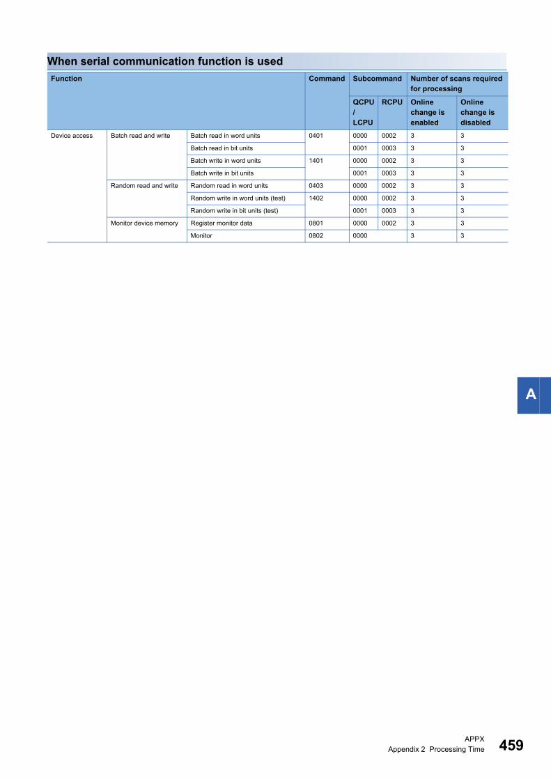
APPXAppendix 2 Processing Time 459
A
When serial communication function is used
Function Command Subcommand Number of scans required for processing
QCPU/LCPU
RCPU Online change is enabled
Online change is disabled
Device access Batch read and write Batch read in word units 0401 0000 0002 3 3
Batch read in bit units 0001 0003 3 3
Batch write in word units 1401 0000 0002 3 3
Batch write in bit units 0001 0003 3 3
Random read and write Random read in word units 0403 0000 0002 3 3
Random write in word units (test) 1402 0000 0002 3 3
Random write in bit units (test) 0001 0003 3 3
Monitor device memory Register monitor data 0801 0000 0002 3 3
Monitor 0802 0000 3 3

460APPXAppendix 3 Compatibility with Multiple CPU Systems
Appendix 3 Compatibility with Multiple CPU SystemsThis section explains data communication using MC protocol when CPU modules are configured in the multiple CPU system.
By setting routing parameters (communication route) in advance, accessing programmable controllers in the
following network systems are available.
• CC-Link IE Controller Network
• CC-Link IE Field Network
• MELSECNET/H
• MELSECNET/10
• Ethernet
Up to 8 target networks (relay stations: 7 stations) can be accessed.
When RCPU is configured in the multiple CPU system
When using C24/E71 in the multiple CPU system of RCPU, refer to the following manual.
MELSEC iQ-R Module Configuration Manual
Accessing multiple CPU system on connected station (host station)
■Accessing multiple CPU system on connected station (host station) from external devicesControl CPU (set with Engineering tool) and non-control CPU of C24 can be accessed.
The usable commands vary depending on the access target RCPU (control CPU, non-control CPU).
Accessing multiple CPU system on other station
■Accessing multiple CPU system on the other station (access station)Control CPU and non-control CPU of the network module connected to the relay station can be accessed.
The usable command vary depending on the access target RCPU (control CPU, non-control CPU).
The modules which can be accessed to other stations via network are as follows.
• CC-Link IE, MELSECNET/H, MELSECNET/10 Network Module
• C24
• E71
External device
Host stationPersonal computerCommunication using engineering toolCommunication using the MC protocol
Setting from the engineering tool
CC-Link IE Controller NetworkAnother station can be accessed whether the control CPU of the module acting as a relay is the same or different.Relay station
: CPU No.1: CPU No.2: CPU No.3: CPU No.4
:Relay module controlled by CPU No.1CC-Link IE Controller Network:C24 controlled by CPU No.1:Relay module controlled by CPU No.2Access station:Relay module controlled by CPU No.2
Relay module: CC-Link IE Controller Network module
Another station can be accessed whether the control CPU of the module acting as a relay is the same or different.
1 2 3 4
1’
21
1
1’
1 2 3 4 21234
1 2 3 4 2
2
2’
2’

APPXAppendix 3 Compatibility with Multiple CPU Systems 461
A
When QCPU is configured in the multiple CPU system
When using C24/E71 in the multiple CPU system of QCPU, refer to the following manual.
QCPU User's Manual (Multiple CPU System)
Accessing multiple CPU system on connected station (host station)
■When using C24/E71 in the multiple CPU systemUse C24/E71 of which function version is B.
■Accessing multiple CPU system on connected station (host station) from external devicesControl CPU (set with Engineering tool) and non-control CPU of C24/E71 can be accessed.
The usable commands vary depending on the access target QCPU (control CPU, non-control CPU).
Using C24/E71 of which function version is A is also possible. In this case, QCPU No.1 is the control CPU of C24/E71.
Only the control CPU of C24/E71 can be accessed when accessing QCPU on the connected station (host station) from
external devices.
Accessing multiple CPU system on other station
■Use the modules of which function version is B for each station.Use the modules of which function version is B for each station as shown below.
■Accessing multiple CPU system on the other station (access station)Control CPU and non-control CPU of the network module connected to the relay station can be accessed.
The usable commands vary depending on the access target QCPU (control CPU, non-control CPU).
When accessing other stations from external devices, and any module of which function version is A is included in the above
modules of connected station (host station), relay station, or access station, only the control CPU of network module
connected to the relay station can be accessed. In addition, accessing other station via a module which is controlled by the
same control CPU is available.
The modules which can be accessed other stations via network are as follows.
• CC-Link IE, MELSECNET/H ,MELSECNET/10 Network module
• C24
• E71
Type Module Remarks
Connected
station (host
station)
QCPU
C24/E71 connected to external device Set the same control CPU for C24/E71 and network module.
Network module connected to relay station/access station
Relay
station
QCPU
Two modules connecting the network between the host station
side and the access station side
Access
station
QCPU
Network module connected to relay station

462APPXAppendix 4 Applicable Commands for Online Program Change
Appendix 4 Applicable Commands for Online Program Change
This section explains the applicability of each command according to the STOP/RUN status of CPU module and the settings
by supported devices.
In this section, the commands that cannot be executed while CPU module is in the RUN status and the commands to enable/
disable the online change with Engineering tool are shown. The commands not listed in the following tables can be used
regardless of the CPU STOP/RUN status.
Commands that cannot be executed during RUNThe following commands cannot be executed while the CPU module is in RUN.
Set the CPU module to STOP and perform the command.
File handlingThe file operation to specify the following files cannot be performed during RUN.
*1 For details on the operations for the files of RCPU, refer to the following manual.MELSEC iQ-R CPU Module User's Manual (Application)
Module control
Commands that enable/disable online changeThe following shows the commands which can be executed while the CPU module is in the RUN status only when the online
change is set to be enabled.
: Executable, :Not executable
Type Command CPU module Target file
Write • Copy file (command: 1824)
• Modify file attribute (command: 1825)
• Modify file creation date and time (command: 1826)
• Write to file (command: 1829)
RCPU Current execution file*1
Q/LCPU • Parameter file (*.QPA)
• Current execution file of program
memory (Drive name: 00H)
• Write to file (command: 1203)
• Copy file (command: 1206)
• Modify file information (command: 1204)
• Modify file name, attribute, file size (command: 1204)
• Batch modify file information (command: 1204)
QnACPU • Parameter file (*.QPA)
• Currently executing file in the
built-in RAM (drive name: 00H)
Deleting • Delete file (command: 1822) RCPU Current execution file*1
Q/LCPU • Program file (*.QPG)
• Parameter file (*.QPA)
• Boot setting file (*.QBT)• Delete file (command: 1205) QnACPU
Type Command CPU module
Remote control • Remote latch clear (command: 1005)
• Remote RESET (command: 1006)
RCPU
Q/LCPU
Defragmentation of
drive memory
• Defragment drive memory (command: 1207) QnACPU
CPU state STOP RUN
Setting of online change Enable/Disable Enable Disable
Applicability of command execution

APPXAppendix 4 Applicable Commands for Online Program Change 463
A
Commands for 4C /3C/2C/4E/3E frame
*1 For E71, data can be copied even if Online program change function is set to prohibit.
Commands for 1C/1E frame
Setting method for writing data to CPU during RUNThe setting to allowed/prohibit of Online program change function can be performed on the following screen of Engineering
tool.
For details of the setting, refer to the user's manual of the supported device (C24/E71) used.
GX Works3 • C24: "Module Parameter" screen (transmission setting)
• E71: "Module Parameter" screen (Own Node Settings)
GX Works2 • C24: "Switch Settings" screen of Intelligent functional module (Transmission setting)
• E71: "Ethernet Operation Setting" screen
GX Developer • C24: "Switch Setting for I/O and Intelligent Function Module" screen (Switch 1, b6 of switch 3)
• E71: "Ethernet Operation Setting" screen
Type Command 4C, 3C, 4E, 3E 2C
Device access Batch write in word units 1401 4
Batch write in bit units 3
Random write in word units (test) 1402 7
Random write in bit units (test) 6
Batch write multiple blocks 1406
Label access Batch write array type labels 141A
Random write labels 1418
File control Create new file 1820
Delete file 1822
Copy file*1 1824
Modify file attribute 1825
Modify file creation date and time 1826
Write to file 1829
Create new file 1202
Write to file 1203
Modify file information 1204
Delete file 1205
Type Command 1C 1E
Device memory Batch write Bit units BW, JW 02H
Word units WW, QW 03H
Test (random write) Bit units BT, JT 04H
Word units WT, QT 05H
Extended file register Batch write EW 18H
Test (random write) ET 19H
Direct write Word units NW 3CH
Intelligent function
module
Batch write TW 0FH

464APPXAppendix 5 Number of Processing per One Communication
Appendix 5 Number of Processing per One Communication
The following shows the number of processing per one communication with each command.
Commands for 4C/3C/4E/3E frame
Device accessThe letter in the column of 'Access target' indicates the following module.
• R/Q/L: MELSEC iQ-R series, MELSEC-Q series, or MELSEC-L series module
• QnA: MELSEC-QnA series and other station module via MELSEC-QnA series network module
• A: MELSEC-QnA series module
For the restrictions of access target for each command and subcommand type, refer to the following section.
Page 469 Accessible Modules for Each Command
Function Command Subcommand Condition Number of points processed per communication
R/Q/L QnA A
Batch read
and write
Batch read in word units 0401 0000
0002
Word device points 960 points 480 points 64 points
Bit device points 960 words
(15360
points)
480 words
(7680
points)
32 words
(512
points)
Batch read in bit units 0001
0003
C24 7904 points 3952 points 256 points
E71 (ASCII code) 3584 points 1792 points
E71 (Binary code) 7168 points 3584 points
Batch write in word units 1401 0000
0002
Word device points 960 points 480 points 64 points
Bit device points 960 words
(15360
points)
480 words
(7680
points)
10 words
(160
points)
Batch write in bit units 0001
0003
C24 7904 points 3952 points 160 points
E71 (ASCII code) 3584 points 1792 points
E71 (Binary code) 7168 points 3584 points
Random read
and write
Random read in word units 0403 0000 Number of word access
points + Number of double
word access points
192 points 96 points
0002
008
96 points
Random write in word units
(test)
1402 0000 (Number of word access
points 12) + (Number of
double word access points
14)
1920 points 960 points 10 points
0002
008
960 points
Random write in bit units
(test)
0001 Number of bit access points 188 points 94 points 20 points
0003
008
94 points
Batch read
and write
multiple
blocks
Batch read multiple blocks 0406 0000 Number of word device
blocks + Number of bit
device blocks
120 points
0002
008
60 points
Batch write multiple blocks 1406 0000 120 points
0002
008
60 points
Monitor
device
memory
Register monitor data 0801 0000 Number of word access
points + Number of double
word access points
192 points 96 points
0002
008
96 points
Monitor 0802 0000 Read data (Number of registered points)

APPXAppendix 5 Number of Processing per One Communication 465
A
Label access
Buffer memory access
Module control
File control
Function Command Subcommand Number of points processed per communication
Batch read and write Batch read array type labels 041A 0000 Depend on the label name length (total number of bytes are
1920 bytes or less)Batch write array type labels 141A 0000
Random read and
write
Random read labels 041C 0000
Random write labels 141B 0000
Function Command Subcommand Number of points processed per communication
Buffer memory Batch read 0613 0000 480 words (960 bytes)
Batch write 1613 0000
Intelligent function
module
Batch read 0601 0000 1920 bytes (960 words)
Batch write 1601 0000
Function Command Subcommand Number of points processed per communication
Remote control Remote RUN 1001 0000 (1 station)
Remote STOP 1002 0000 (1 station)
Remote PAUSE 1003 0000 (1 station)
Remote latch clear 1005 0000 (1 station)
Remote RESET 1006 0000 (1 station)
Read CPU model name 0101 0000 (1 station)
Remote password Unlock 1630 0000
Lock 1631 0000
Loopback test 0619 0000 960 bytes (applicable only with a connected station)
Clear error information 1617 000 (1 station)
Function Command Subcommand Number of points processed per communication
File check Read directory/file information 1810 0000
0040
(for 36)
Search directory/file
information
1811 0000
0040
(for 1)
File creation and
deletion
Create new file 1820 0000
0040
(for 1)
Delete file 1822 0000
0004
0040
(for 1)
Copy file 1824 0000
0004
0040
(for 1)
File modification Modify file attribute 1825 0000
0004
0040
(for 1)
Modify file creation date and
time
1826 0000
0040
(for 1)
Open file 1827 0000
0004
0040
(for 1)
Read file 1828 0000
0040
1920 bytes
Write to file 1829 0000
0040
1920 bytes
Close file 182A 0000
0040
(for 1)

466APPXAppendix 5 Number of Processing per One Communication
Serial communication module dedicated commands
QnA dedicated commands
Function Command Subcommand Number of points processed per communication
User frame Read registered data 0610 0000 80 bytes
Register data 1610 0000 (1 station)
Delete registered data 0001 (for 1 station/all stations)
Global 1618 0000
0001
(for 1 station/all stations)
Initialize transmission sequence 1615 0000 (1 station)
Switch mode 1612 0000 (1 station)
Programmable
controller CPU
monitoring
Register 0630 0000 960 points
Deregister 0631 0000
On-demand 2101 (1 station)
Function Command Subcommand Number of points processed per communication
Drive memory
defragmentation
Read memory usage status 0205 0000 (256 clusters)
Defragment memory 1207 0000 (1 station)
File control Read file
information
table
Without header
statement
0201 0000 (for 36)
With header
statement
0202 0000 (for 16)
Read file presence
(Search file)
0203 0000 (for 1)
Read file No. usage status 0204 0000 (for 256)
Read file 0206 0000 960 bytes
Lock file 0808 0001 (for 1)
0000
Create new file (Register file name) 1202 0000 (for 1)
Write to file 1203 0000 960 bytes
0001 For file size
Modify file information 1204 0000 (for 1)
0001
0002
Delete file 1205 0000 (for 1)
Copy file 1206 0000 480 bytes

APPXAppendix 5 Number of Processing per One Communication 467
A
Commands for 2C frameRefer to the processing points of the corresponding commands for 4C/3C/4E/3E frame
Commands for 1C frame
*1 For ACPU other than AnA/AnU, device X (input) has two processing points per point. When the X is included in the specified device, set the number of device points to meet the following.((Specified points for X 2) + Specified points for other devices) Number of points processed per communication.If only X is specified, the number of points processed per one communication will be one half the value shown in the table.
Function Command Number of points processed per communication
Device memory Batch read Bit units BR
JR
256 points
Word units Bit device WR
QR
32 words (512 points)
Word device 64 points
Batch write Bit units BW
JW
160 points
Word units Bit device WW
QW
10 words (160 points)
Word device 64 points
Test (random write) Bit units BT
JT
20 points
Word units Bit device WT
QT
10 words (160 points)
Word device 10 points
Register monitor data Bit units BM
JM
40 points*1
Word units Bit device WM
QM
20 words (320 points)*1
Word device 20 points
Monitor Bit units MB
MJ
Number of registered points
Word units MN
MQ
Number of registered points
Extended file
register
Batch read ER 64 points
Batch write EW 64 points
Test (random write) ET 10 points
Register monitor data EM 20 points
Monitor ME Number of registered points
Direct read Word units NR 64 points
Direct write Word units NW 64 points
Special function
module
Batch read TR 128 bytes
Batch write TW 128 bytes
Loopback test TT 254 bytes
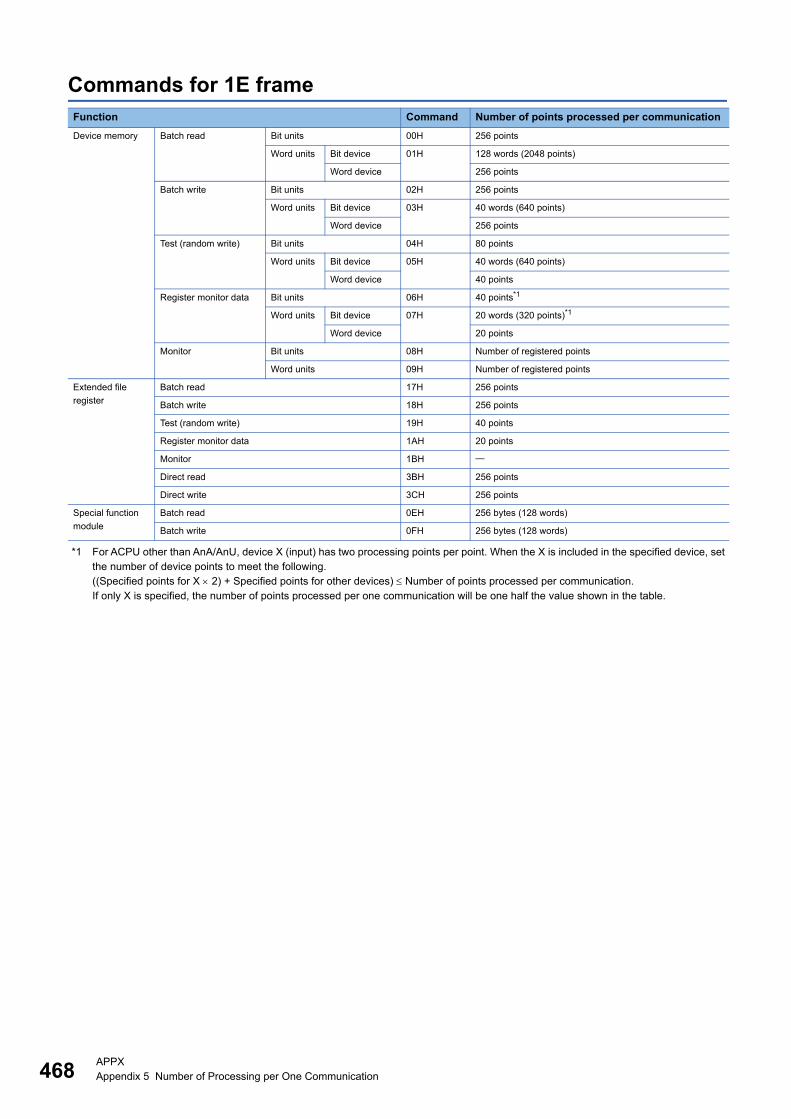
468APPXAppendix 5 Number of Processing per One Communication
Commands for 1E frame
*1 For ACPU other than AnA/AnU, device X (input) has two processing points per point. When the X is included in the specified device, set the number of device points to meet the following.((Specified points for X 2) + Specified points for other devices) Number of points processed per communication.If only X is specified, the number of points processed per one communication will be one half the value shown in the table.
Function Command Number of points processed per communication
Device memory Batch read Bit units 00H 256 points
Word units Bit device 01H 128 words (2048 points)
Word device 256 points
Batch write Bit units 02H 256 points
Word units Bit device 03H 40 words (640 points)
Word device 256 points
Test (random write) Bit units 04H 80 points
Word units Bit device 05H 40 words (640 points)
Word device 40 points
Register monitor data Bit units 06H 40 points*1
Word units Bit device 07H 20 words (320 points)*1
Word device 20 points
Monitor Bit units 08H Number of registered points
Word units 09H Number of registered points
Extended file
register
Batch read 17H 256 points
Batch write 18H 256 points
Test (random write) 19H 40 points
Register monitor data 1AH 20 points
Monitor 1BH
Direct read 3BH 256 points
Direct write 3CH 256 points
Special function
module
Batch read 0EH 256 bytes (128 words)
Batch write 0FH 256 bytes (128 words)

APPXAppendix 6 Accessible Modules for Each Command 469
A
Appendix 6 Accessible Modules for Each CommandThe following shows the access target modules that can be specified by a request message.
For the functions and commands which can be used for supported devices, refer to the user's manual of each device.
Access target modulesThe character in the column of 'Access target' indicates the following module.
• R: MELSEC-iQ-R series CPU module and mounted intelligent function module
• Q/L: MELSEC-Q series or MELSEC-L series CPU module and the mounted intelligent functional module
• QnA: MELSEC-QnA series CPU module and mounted special function module
• A: MELSEC-A series CPU module and mounted special function module
• QS: Safety CPU module and the mounted intelligent functional module
• H: Module of MELSECNET/H remote station
• 10: Module of MELSECNET/10 remote station
• Head(R): MELSEC iQ-R CC-Link IE Field Network remote head module
• Head(L): Head module of CC-Link IE Field Network
Commands for 4C/3C/4E/3E frame
Device access: Executable, : Executable (with restrictions), : Not executable
Function Command Subcommand Access target Reference
CPU module Remote I/O Head
R L Q QnA A QS H 10 R L
Batch read
and write
0401 0000
0080
*1 *1 Page 86 Batch read in word
units (command: 0401)
0002
0082
*2 *2
0001
0081
*1 *1 Page 90 Batch read in bit
units (command: 0401)
0003
0083
*2 *2
1401 0000
0080
*1 *1 Page 92 Batch write in word
units (command: 1401)
0002
0082
*2 *2
0001
0081
*1 *1 Page 95 Batch write in bit
units (command: 1401)
0003
0083
*2 *2
Random read
and write
0403 0000
0080
*1 *1 Page 97 Random read in
word units (command: 0403)
0040
00C0
*3
0002
0082
*2 *2
1402 0000
0080
*1 *1 Page 104 Random write in
word units (test) (command:
1402)0002
0082
*2 *2
0001
0081
*1 *1 Page 108 Random write in bit
units (test) (command: 1402)
0003
0083
*2 *2

470APPXAppendix 6 Accessible Modules for Each Command
*1 Specify the device with the specification method of MELSEC-Q/L series. The added new devices for MELSEC iQ-R and their ranges cannot be specified.
*2 The command can be used when both access target and connected station are MELSEC iQ-R series module.*3 The command can be specified when using Basic model QCPU, High Performance model QCPU, and Process CPU.*4 QnACPU and Q2AS(H) CPU with the version 9707B or later can be used.
Label accessThe command can be used when both access target and connected station are MELSEC iQ-R series module.
Page 123 LABEL ACCESS
Buffer memory access: Executable, : Executable (with restrictions), : Not executable
*1 The command can only be used for C24 (including multidrop connection station) and E71 connected to the external device.
Batch read
and write
multiple
blocks
0406 0000
0080
*1 *4 *1 Page 110 Batch read multiple
blocks (command: 0406)
0002
0082
*2 *2
1406 0000
0080
*1 *4 *1 Page 114 Batch write multiple
blocks (command: 1406)
0002
0082
*2 *2
Monitor
device
memory
0801 0000
0080
*1 *1 Page 119 Register monitor
data (command: 0801)
0040
00C0
*3
0002
0082
*2 *2
0802 0000 Page 120 Monitor (command:
0802)
Function Command Subcommand Access target Reference
CPU module Remote I/O Head
R L Q QnA A QS H 10 R L
Buffer memory 0613 0000 *1 Page 152 Batch read
(command: 0613)
1613 0000 *1 Page 154 Batch write
(command: 1613)
Intelligent
function module
0601 0000 Page 160 Batch read
(command: 0601)
1601 0000 Page 162 Batch write
(command: 1601)
Function Command Subcommand Access target Reference
CPU module Remote I/O Head
R L Q QnA A QS H 10 R L

APPXAppendix 6 Accessible Modules for Each Command 471
A
Module control: Executable, : Executable (with restrictions), : Not executable
*1 The command can only be used for C24 (including multidrop connection station) and E71 connected to the external device.*2 The command can only be used for E71 connected to an external device.
File control: Executable, : Executable (with restrictions), : Not executable
Function Command Subcommand Access target Reference
CPU module Remote I/O Head
R L Q QnA A QS H 10 R L
Remote control 1001 0000 Page 171 Remote RUN
(command: 1001)
1002 0000 Page 173 Remote STOP
(command: 1002)
1003 0000 Page 174 Remote PAUSE
(command: 1003)
1005 0000 Page 175 Remote latch
clear (command: 1005)
1006 0000 Page 176 Remote RESET
(command: 1006)
0101 0000 Page 177 Read CPU
model name (command:
0101)
Remote
password
1630 0000 *1 Page 179 Unlock
(command: 1630)
1631 0000 *2 Page 181 Lock (command:
1631)
Loopback test 0619 0000 *1 Page 183 Loopback test
(command: 0619)
Clear error
information
1617 0000 *1 Page 185 Turn indicator
LED OFF, initialize error
code (command: 1617)
Function Command Subcommand Access target Reference
CPU module Remote I/O Head
R L Q QnA A QS H 10 R L
File check 1810 0000 Page 209 Read directory/
file information
(command: 1810)0040 *1 *1
1811 0000 Page 215 Search
directory/file information
(command: 1811)0040 *1 *1
File creation
and deletion
1820 0000 Page 218 Create new file
(command: 1820)0040 *1 *1
1822 0000 *2 *2 Page 221 Delete file
(command: 1822)0004 *3
0040 *1 *1
1824 0000 *2 *2 Page 224 Copy file
(command: 1824)0004 *3
0040 *1 *1
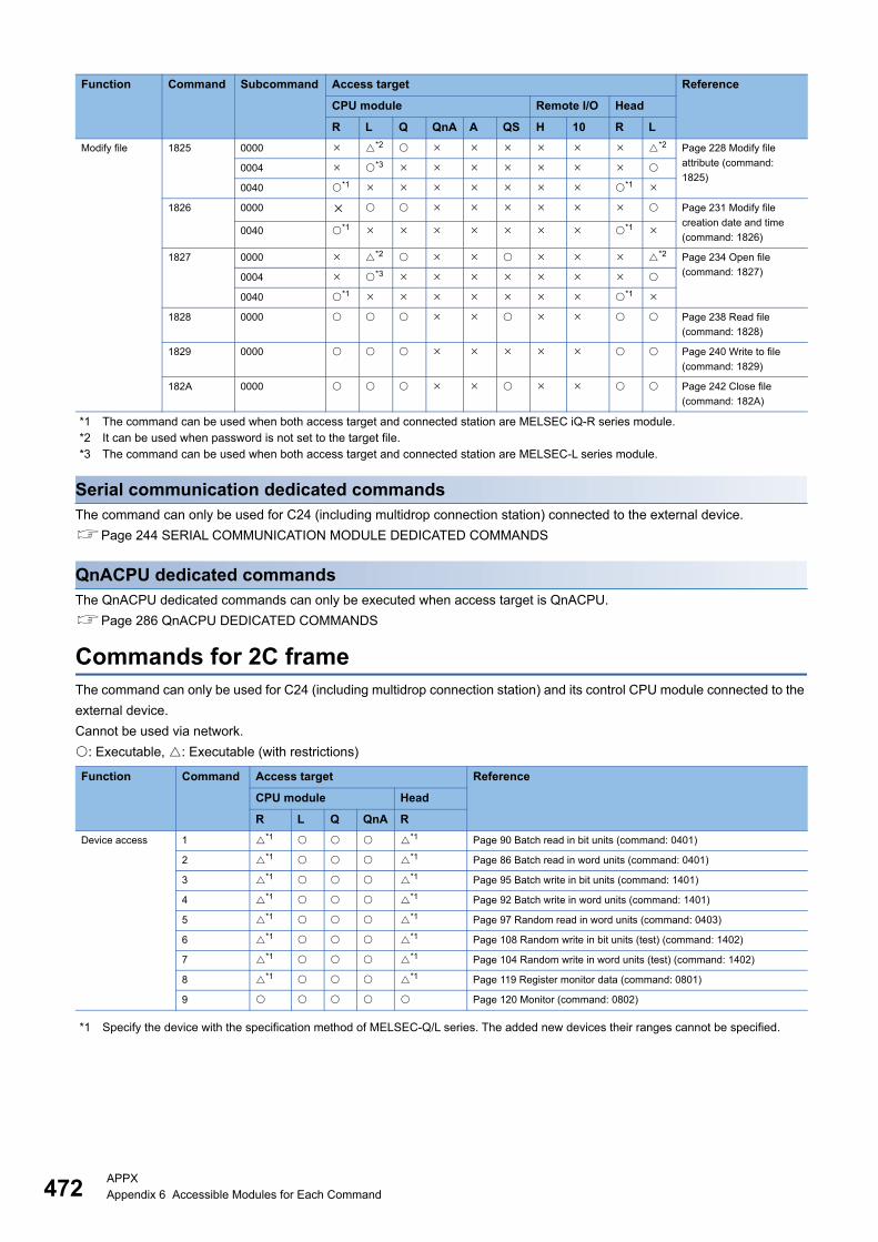
472APPXAppendix 6 Accessible Modules for Each Command
*1 The command can be used when both access target and connected station are MELSEC iQ-R series module.*2 It can be used when password is not set to the target file.*3 The command can be used when both access target and connected station are MELSEC-L series module.
Serial communication dedicated commandsThe command can only be used for C24 (including multidrop connection station) connected to the external device.
Page 244 SERIAL COMMUNICATION MODULE DEDICATED COMMANDS
QnACPU dedicated commandsThe QnACPU dedicated commands can only be executed when access target is QnACPU.
Page 286 QnACPU DEDICATED COMMANDS
Commands for 2C frameThe command can only be used for C24 (including multidrop connection station) and its control CPU module connected to the
external device.
Cannot be used via network.
: Executable, : Executable (with restrictions)
*1 Specify the device with the specification method of MELSEC-Q/L series. The added new devices their ranges cannot be specified.
Modify file 1825 0000 *2 *2 Page 228 Modify file
attribute (command:
1825)0004 *3
0040 *1 *1
1826 0000 Page 231 Modify file
creation date and time
(command: 1826)0040 *1 *1
1827 0000 *2 *2 Page 234 Open file
(command: 1827)0004 *3
0040 *1 *1
1828 0000 Page 238 Read file
(command: 1828)
1829 0000 Page 240 Write to file
(command: 1829)
182A 0000 Page 242 Close file
(command: 182A)
Function Command Access target Reference
CPU module Head
R L Q QnA R
Device access 1 *1 *1 Page 90 Batch read in bit units (command: 0401)
2 *1 *1 Page 86 Batch read in word units (command: 0401)
3 *1 *1 Page 95 Batch write in bit units (command: 1401)
4 *1 *1 Page 92 Batch write in word units (command: 1401)
5 *1 *1 Page 97 Random read in word units (command: 0403)
6 *1 *1 Page 108 Random write in bit units (test) (command: 1402)
7 *1 *1 Page 104 Random write in word units (test) (command: 1402)
8 *1 *1 Page 119 Register monitor data (command: 0801)
9 Page 120 Monitor (command: 0802)
Function Command Subcommand Access target Reference
CPU module Remote I/O Head
R L Q QnA A QS H 10 R L

APPXAppendix 6 Accessible Modules for Each Command 473
A
Commands for 1C frame: Executable, :Not executable
*1 When accessing Universal model QCPU, use the module with a serial number whose first five digits are '10102' or later. If using a module with a serial number whose first five digits are '10101' or earlier, access with 2C/3C/4C frame.
*2 Read/write the devices within the range of AnCPU, AnNCPU, AnACPU, or AnUCPU. The added new devices and their ranges cannot be specified.
*3 The command can only be used for C24 (including multidrop connection station) connected to the external device.
Function Command Access target Reference
CPU module Remote I/O Head
R L Q*1 QnA A QS H R
Device
memory
Batch read Bit units BR
JR
*2 *2 *2 *2 *2 *2 *2 Page 352 Batch read (bit
units) (command: BR, JR)
Word units WR
QR
*2 *2 *2 *2 *2 *2 *2 Page 354 Batch read (word
units) (command: WR, QR)
Batch write Bit units BW
JW
*2 *2 *2 *2 *2 *2 Page 356 Batch write (bit
units) (command: BW, JW)
Word units WW
QW
*2 *2 *2 *2 *2 *2 Page 358 Batch write (word
units) (command: WW, QW)
Test
(random
write)
Bit units BT
JT
*2 *2 *2 *2 *2 *2 Page 360 Test (random
write) (bit units) (command:
BT, JT)
Word units WT
QT
*2 *2 *2 *2 *2 *2 Page 362 Test (random
write) (word units)
(command: WT, QT)
Register
monitor
data
Bit units BM
JM
*2 *2 *2 *2 *2 *2 Page 365 Register monitor
data (bit units) (command:
BM, JM)
Word units WM
QM
*2 *2 *2 *2 *2 *2 Page 366 Register monitor
data (word units)
(command: WM, QM)
Monitor Bit units MB
MJ
Page 367 Monitor (bit units)
(command: MB, MJ)
Word units MN
MQ
Page 368 Monitor (word
units) (command: MN, MQ)
Extended
file
register
Batch read ER Page 373 Batch read
(command: ER)
Batch write EW Page 374 Batch write
(command: EW)
Test (random write) ET Page 375 Test (random
write) (command: ET)
Register monitor data EM Page 377 Register monitor
data (command: EM)
Monitor ME Page 378 Monitor
(command: ME)
Direct read Word units NR Page 379 Direct read
(command: NR)
Direct write Word units NW Page 380 Direct write
(command: NW)
Special
function
module
Batch read TR Page 384 Batch read
(command: TR)
Batch write TW Page 386 Batch write
(command: TW)
Loopback test TT *3 Page 387 Loopback test
(Command: TT)

474APPXAppendix 6 Accessible Modules for Each Command
Commands for 1E frame: Executable, :Not executable
*1 When accessing Universal model QCPU, use the module with a serial number whose first five digits are '10102' or later. If using a module with a serial number whose first five digits are '10101' or earlier, access with 3E/4E frame.In addition, when accessing a built-in Ethernet port CPU, refer to the following manual. QnUCPU User's Manual (Communication via Built-in Ethernet Port)
*2 Read/write the devices within the range of AnACPU. The added new devices and their ranges cannot be specified.*3 The devices that can be registered to E71 is for 1 command out of the three types of commands (06H, 07H, 1AH).
The specified device recently used by any of the above commands is registered to E71.
Function Command Access target Reference
CPU module
L Q*1 QnA
A QS
Device memory Batch read Bit units 00H *2 *2 *2 *2 Page 401 Batch read in bit units (command: 00)
Word units 01H *2 *2 *2 *2 Page 403 Batch read in word units (command: 01)
Batch write Bit units 02H *2 *2 *2 Page 405 Batch write in bit units (command: 02)
Word units 03H *2 *2 *2 Page 407 Batch write in word units (command: 03)
Test (random
write)
Bit units 04H *2 *2 *2 Page 408 Test in bit units (random write) (command: 04)
Word units 05H *2 *2 *2 Page 410 Test in word units (random write) (command:
05)
Register
monitor
data*3
Bit units 06H *2 *2 *2 Page 413 Register monitor data(command: 06, 07)
Word units 07H *2 *2 *2
Monitor Bit units 08H Page 414 Monitor in bit units (command: 08)
Page 415 Monitor in word units (command: 09)Word units 09H
Extended file
register
Batch read 17H Page 417 Batch read (command: 17)
Batch write 18H Page 419 Batch write (command: 18)
Test (random write) 19H Page 421 Test (random write) (command: 19)
Register monitor data*3 1AH Page 424 Register monitor data (command: 1A)
Monitor 1BH Page 425 Monitoring (command: 1B)
Direct read 3BH Page 426 Direct read (command: 3B)
Direct write 3CH Page 428 Direct write (command: 3C)
Special function
module
Batch read 0EH Page 432 Batch read (command: 0E)
Batch write 0FH Page 434 Batch write (command: 0F)

APPXAppendix 7 Setting Examples 475
A
Appendix 7 Setting ExamplesThis section explains the setting example of the message.
Setting examples of message for serial communication moduleThe following shows the setting example when using a command from a serial communication module.
Examples of device access in ASCII code (Format 1, 3C frame)The following shows the setting example when using a command for format 1 and 3C frame.
■Device reading• Format 1 (sum check enabled), 3C frame
• Access target: QCPU of the connected station (host station)
• Command: Batch read in word units (command: 0401)
• Device: M100 to M131 (for 2 words)
1. Read values from devices.
Request message
*1 The addition result of the sum check range: 22BH+3DF=60AH
2. Receive the result.
Response message (Normal completion: Response data)
*1 The addition result of the sum check range: 22BH + 18F = 3BAH*2 The value of read data corresponds to the access target device as follows.
Control code
Frame ID No. Access route
Station No. Network No. PC No. Self-station No.
ENQ 3C frame Host station
F 9 0 0 0 0 F F 0 0
05H 46H 39H 30H 30H 30H 30H 46H 46H 30H 30H
The subtotal of the additional value of binary data = 22BH
Request data Sum check code*1
Command Subcommand Device code Head device number Number of device points
0 4 0 1 0 0 0 0 M * 0 0 0 1 0 0 0 0 0 2 0 A
30H 34H 30H 31H 30H 30H 30H 30H 4DH 2AH 30H 30H 30H 31H 30H 30H 30H 30H 30H 32H 30H 41H
The subtotal of the additional value of binary data = 3DFH
Control code Frame ID No. Access route
Station No. Network No. PC No. Self-station No.
STX 3C frame Host station
F 9 0 0 0 0 F F 0 0
02H 46H 39H 30H 30H 30H 30H 46H 46H 30H 30H
The subtotal of the additional value of binary data = 22BH
Response data (read data)*2 Control code Sum check code*1
1 2 3 4 0 0 0 2 ETX B A
31H 32H 33H 34H 30H 30H 30H 32H 03H 42H 41H
The subtotal of the additional value of binary data = 18FH
1
M115
1 2 3 4 0 0 0 20 0 0 1 0 0 1 0 0 0 1 1 0 1 0 0 0 0 0 0 0 0 0 0 0 0 0 0 0 0 1 0
2 3 431H 32H 33H 34H
0 0 030H 30H 30H
232H
M100 M131 M116
0 = OFF1 = ON
to to

476APPXAppendix 7 Setting Examples
■Device writing • Format 1 (sum check enabled), 3C frame
• Access target: QCPU of the connected station (host station)
• Command: Batch write in word units (command: 1401)
• Device: M100 to M131 (for 2 words)
1. Write values to devices.
Request message
*1 The addition result of the sum check range: 22BH + 3E0H + 1C2H = 7CDH*2 The value of write data corresponds to the access target device as follows.
2. Receive the result.
Response message (Normal completion: No response data)
Control code Frame ID No. Access route
Station No. Network No. PC No. Self-station No.
ENQ 3C frame Host station
F 9 0 0 0 0 F F 0 0
05H 46H 39H 30H 30H 30H 30H 46H 46H 30H 30H
The subtotal of the additional value of binary data = 22BH
Request data
Command Subcommand Device code Head device number Number of device points
1 4 0 1 0 0 0 0 M * 0 0 0 1 0 0 0 0 0 2
31H 34H 30H 31H 30H 30H 30H 30H 4DH 2AH 30H 30H 30H 31H 30H 30H 30H 30H 30H 32H
The subtotal of the additional value of binary data = 3E0H
Request data Sum check code*1
Write data*2
2 3 4 7 A B 9 6 C D
32H 33H 34H 37H 41H 42H 39H 36H 43H 44H
The subtotal of the additional value of binary data = 1C2H
Control code
Frame ID No. Access route
Station No. Network No. PC No. Self-station No.
ACK 3C frame Host station
F 9 0 0 0 0 F F 0 0
06H 46H 39H 30H 30H 30H 30H 46H 46H 30H 30H
2 3 432H 33H 34H
7 A B37H 41H 42H
9 639H 36H
M115
2 3 4 7 A B 9 60 0 1 0 0 0 1 1 0 1 0 0 0 1 1 1 1 0 1 0 1 0 1 1 1 0 0 1 0 1 1 0
M100 M131 M116
0 OFF1 ON
toto

APPXAppendix 7 Setting Examples 477
A
Examples of device access in binary code (Format 5, 4C frame)The following shows the setting example when using a command for format 5 and 4C frame.
■Device reading • Format 5 (sum check enabled), 4C frame
• Access target: QCPU of the connected station (host station)
• Command: Batch read in word units (command: 0401)
• Device: M100 to M131 (for 2 words)
1. Read values from devices.
Request message
*1 Frame ID No. (1 byte) + Access route (7 bytes) + Request data (10 bytes)*2 The addition result of the sum check range: 30BH + FBH = 406H
2. Receive the result.
Response message (Normal completion: Response data)
*1 Frame ID No. (1 byte) + Access route (7 bytes) + Response ID code (2 bytes) + Normal completion code (2 bytes) + Response data (4 bytes)
*2 Additional code. Calculate the sum check code except for the additional code. (Page 35 Additional code (10H))*3 The addition result of the sum check range: 309H + 246h = 54FH*4 The value of read data corresponds to the access target device as follows.
Control code Number of data bytes*1
Frame ID No.
Access route
Station No.
Network No. PC No. Request destination module I/O No.
Request destination module station No.
Self-station No.
DLE STX 18 bytes 4C frame Host station
10H 02H 12H 00H F8H 00H 00H FFH FFH 03H 00H 00H
The subtotal of the additional value of binary data = 30BH
Request data Control code Sum check code*2
Command Subcommand Head device number
Device code Number of device points
0401 0000 100 M 2 DLE ETX 0 6
01H 04H 00H 00H 64H 00H 00H 90H 02H 00H 10H 03H 30H 36H
The subtotal of the additional value of binary data = FBH
Control code Number of data bytes*1
Frame ID No.
Access route
Station No.
Network No. PC No. Request destination module I/O No.
Request destination module station No.
Self-station No.
DLE STX 16 bytes 4C frame Host station
10H 02H 10H 10H 00H F8H 00H 00H FFH FFH 03H 00H 00H
*2 The subtotal of the additional value of binary data = 309H
Response ID code
Normal completion code
Response data (read data)*4 Control code Sum check code*3
FFFFH 0000H M100 to M115 M116 to M131 DLE ETX 4 F
FFH FFH 00H 00H 34H 12H 02H 00H 10H 03H 34H 46H
The subtotal of the additional value of binary data = 246H
M107
3 4 1 2 0 2 0 00 0 1 1 0 1 0 0 0 0 0 1 0 0 1 0 0 0 0 0 0 0 1 0 0 0 0 0 0 0 0 0
34H 12H 02H 00H
M100 M115 M108 M123 M116 M131 M124
0 = OFF1 = ON
to to to to

478APPXAppendix 7 Setting Examples
■Device writing • Format 5 (sum check enabled), 4C frame
• Access target: QCPU of the connected station (host station)
• Command: Batch write in word units (command: 1401)
• Device: M100 to M131 (for 2 words)
1. Write values to devices.
Request message
*1 Frame ID No. (1 byte) + Access route (7 bytes) + Request data (14 bytes)*2 The addition result of the sum check range: 30FH + 2B6H = 5C5H*3 The value of write data corresponds to the access target device as follows.
2. Receive the result.
Response message (Normal completion: No response data)
*1 Frame ID No. (1 byte) + Access route (7 bytes) + Response ID code (2 bytes) + Normal completion code (2 bytes)*2 The addition result of the sum check range: 305H + 1FEH = 503H
Control code Number of data bytes*1
Frame ID No.
Access route
Station No.
Network No. PC No. Request destination module I/O No.
Request destination module station No.
Self-station No.
DLE STX 22 bytes 4C frame Host station
10H 02H 16H 00H F8H 00H 00H FFH FFH 03H 00H 00H
The subtotal of the additional value of binary data = 30FH
Request data Control code Sum check code*2
Command Subcommand Head device number
Device code
Number of device points
Write data*3
1401 0000 100 M 2 M100 to M115 M116 to
M131
DLE ETX C 5
01H 14H 00H 00H 64H 00H 00H 90H 02H 00H 47H 23H 96H ABH 10H 03H 43H 35H
The subtotal of the additional value of binary data = 2B6H
Control code Number of data bytes*1
Frame ID No.
Access route
Station No.
Network No. PC No. Request destination module I/O No.
Request destination module station No.
Self-station No.
DLE STX 12 bytes 4C frame Host station
10H 02H 0CH 00H F8H 00H 00H FFH FFH 03H 00H 00H
The subtotal of the additional value of binary data = 305H
Response ID code Normal completion code Control code Sum check code*2
FFFFH 0000H DLE ETX 0 3
FFH FFH 00H 00H 10H 03H 30H 33H
The subtotal of the additional value of binary data = 1FEH
M107 M100 M115 M108 M123 M116 M131 M124
0 = OFF1 = ON
4 7 2 3 9 6 A B0 1 0 0 0 1 1 1 0 0 1 0 0 0 1 1 1 0 0 1 0 1 1 0 1 0 1 0 1 0 1 1
47H 23H 96H ABH
to to to to

APPXAppendix 7 Setting Examples 479
A
Setting examples of message for Ethernet interface moduleThe following shows the setting example when using a command from an Ethernet interface module.
Examples of device access in ASCII code (3E frame)The following shows the setting example when using a command for ASCII code and 3E frame.
■Device reading • ASCII code, 3E frame
• Access target: QCPU of the connected station (host station)
• Command: Batch read in word units (command: 0401)
• Device: M100 to M131 (for 2 words)
1. Read values from devices.
Request message
*1 Monitoring timer (4 bytes) + Request data (20 bytes)
2. Receive the result.
Response message (Normal completion: Response data)
*1 End code (4 bytes) + Response data (8 bytes)*2 The value of read data corresponds to the access target device as follows.
Subheader Access route Request data length*1
Monitoring timer
Network No.
PC No. Request destination module I/O No.
Request destination module station No.
3E frame (request) Host station 24 4 seconds
5 0 0 0 0 0 F F 0 3 F F 0 0 0 0 1 8 0 0 1 0
35H 30H 30H 30H 30H 30H 46H 46H 30H 33H 46H 46H 30H 30H 30H 30H 31H 38H 30H 30H 31H 30H
Request data
Command Subcommand Device code Head device number Number of device points
0 4 0 1 0 0 0 0 M * 0 0 0 1 0 0 0 0 0 2
30H 34H 30H 31H 30H 30H 30H 30H 4DH 2AH 30H 30H 30H 31H 30H 30H 30H 30H 30H 32H
Subheader Access route Response data length*1
End code
Network No.
PC No. Request destination module I/O No.
Request destination module station No.
3E frame (response) Host station 12 0000H
D 0 0 0 0 0 F F 0 3 F F 0 0 0 0 0 C 0 0 0 0
44H 30H 30H 30H 30H 30H 46H 46H 30H 33H 46H 46H 30H 30H 30H 30H 30H 43H 30H 30H 30H 30H
Response data (read data)*2
1 2 3 4 0 0 0 2
31H 32H 33H 34H 30H 30H 30H 32H
1
M115
1 2 3 4 0 0 0 20 0 0 1 0 0 1 0 0 0 1 1 0 1 0 0 0 0 0 0 0 0 0 0 0 0 0 0 0 0 1 0
2 3 431H 32H 33H 34H
0 0 030H 30H 30H
232H
M100 M131 M116
0 = OFF1 = ON
to to

480APPXAppendix 7 Setting Examples
■Device writing • ASCII code, 3E frame
• Access target: QCPU of the connected station (host station)
• Command: Batch write in word units (command: 1401)
• Device: M100 to M131 (for 2 words)
1. Write values to devices.
Request message
*1 Monitoring timer (4 bytes) + Request data (28 bytes)*2 The value of write data corresponds to the access target device as follows.
2. Receive the result.
Response message (Normal completion: No response data)
*1 End code (4 bytes)
Subheader Access route Request data length*1
Monitoring timer
Network No.
PC No. Request destination module I/O No.
Request destination module station No.
3E frame (request) Host station 32 4 seconds
5 0 0 0 0 0 F F 0 3 F F 0 0 0 0 2 0 0 0 1 0
35H 30H 30H 30H 30H 30H 46H 46H 30H 33H 46H 46H 30H 30H 30H 30H 32H 30H 30H 30H 31H 30H
Request data
Command Subcommand Device code Head device number Number of device points
1 4 0 1 0 0 0 0 M * 0 0 0 1 0 0 0 0 0 2
31H 34H 30H 31H 30H 30H 30H 30H 4DH 2AH 30H 30H 30H 31H 30H 30H 30H 30H 30H 32H
Request data
Write data*2
2 3 4 7 A B 9 6
32H 33H 34H 37H 41H 42H 39H 36H
Subheader Access route Response data length*1
End code
Network No.
PC No. Request destination module I/O No.
Request destination module station No.
3E frame (response) Host station 4 0000H
D 0 0 0 0 0 F F 0 3 F F 0 0 0 0 0 4 0 0 0 0
44H 30H 30H 30H 30H 30H 46H 46H 30H 33H 46H 46H 30H 30H 30H 30H 30H 34H 30H 30H 30H 30H
2 3 432H 33H 34H
7 A B37H 41H 42H
9 639H 36H
M115
2 3 4 7 A B 9 60 0 1 0 0 0 1 1 0 1 0 0 0 1 1 1 1 0 1 0 1 0 1 1 1 0 0 1 0 1 1 0
M100 M131 M116
0 OFF1 ON
toto

APPXAppendix 7 Setting Examples 481
A
Examples of device access in binary code (3E frame)The following shows the setting example when using a command for binary code and 3E frame.
■Device reading • Binary code, 3E frame
• Access target: QCPU of the connected station (host station)
• Command: Batch read in word units (command: 0401)
• Device: M100 to M131 (for 2 words)
1. Read values from devices.
Request message
*1 Monitoring timer (2 bytes) + Request data (10 bytes)
2. Receive the result.
Response message (Normal completion: Response data)
*1 End code (2 bytes) + Response data (4 bytes)*2 The value of read data corresponds to the access target device as follows.
Subheader Access route Request data length*1
Monitoring timer
Network No. PC No. Request destination module I/O No.
Request destination module station No.
3E frame (request) Host station 12 4 seconds
50H 00H 00H FFH FFH 03H 00H 0CH 00H 10H 00H
Request data
Command Subcommand Head device number Device code Number of device points
0401 0000 100 M 2
01H 04H 00H 00H 64H 00H 00H 90H 02H 00H
Subheader Access route Response data length*1
End code
Network No. PC No. Request destination module I/O No.
Request destination module station No.
3E frame (response) Host station 6 0000H
D0H 00H 00H FFH FFH 03H 00H 06H 00H 00H 00H
Response data (read data)*2
M100 to M115 M116 to M131
34H 12H 02H 00H
M107
3 4 1 2 0 2 0 00 0 1 1 0 1 0 0 0 0 0 1 0 0 1 0 0 0 0 0 0 0 1 0 0 0 0 0 0 0 0 0
34H 12H 02H 00H
M100 M115 M108 M123 M116 M131 M124
0 = OFF1 = ON
to to to to

482APPXAppendix 7 Setting Examples
■Device writing • Binary code, 3E frame
• Access target: QCPU of the connected station (host station)
• Command: batch write in word units (command: 1401)
• Device: M100 to M131 (for 2 words)
1. Write values to devices.
Request message
*1 Monitoring timer (2 bytes) + Request data (14 bytes)*2 The value of write data corresponds to the access target device as follows.
2. Receive the result.
Response message (Normal completion: No response data)
*1 End code (2 bytes)
Subheader Access route Request data length*1
Monitoring timer
Network No. PC No. Request destination module I/O No.
Request destination module station No.
3E frame (request) Host station 16 4 seconds
50H 00H 00H FFH FFH 03H 00H 10H 00H 10H 00H
Request data
Command Subcommand Head device number
Device code Number of device points
Write data*2
1401 0000 100 M 2 M100 to M115 M116 to M131
01H 14H 00H 00H 64H 00H 00H 90H 02H 00H 47H 23H 96H ABH
Subheader Access route Response data length*1
End code
Network No. PC No. Request destination module I/O No.
Request destination module station No.
3E frame (response) Host station 2 0000H
D0H 00H 00H FFH FFH 03H 00H 02H 00H 00H 00H
M107 M100 M115 M108 M123 M116 M131 M124
0 = OFF1 = ON
4 7 2 3 9 6 A B0 1 0 0 0 1 1 1 0 0 1 0 0 0 1 1 1 0 0 1 0 1 1 0 1 0 1 0 1 0 1 1
47H 23H 96H ABH
to to to to

APPXAppendix 7 Setting Examples 483
A
Setting examples of access routeThe following shows the setting example of each access route for each frame. For the details of each setting item, refer to the
following section.
Page 50 Details of Setting Data
Accessing the connected station (host station)The following shows the setting example for accessing the connected station (host station).
: Unnecessary
Specify the CPU module of an access target in the request destination module I/O No.
Page 56 Accessing multiple CPU system, redundant system
Access target Frame Station No. Network No. PC No. Request destination module I/O No.
Request destination module station No.
Self-station No.
Connected station (host
station)
4C 00 00 FF 03FF 00 00
3C 00 00 FF 00
2C 00 00
1C 00 FF
4E/3E 00 FF 03FF 00
1E FF
Multiple CPU system
(Multiple CPU No.1)
4C 00 00 FF 03E0 00 00
4E/3E 00 FF 03E0 00
Redundant system
(Control system CPU)
4C 00 00 FF 03D0 00 00
4E/3E 00 FF 03D0 00
External device
Connected station(Host station) :Access target station

484APPXAppendix 7 Setting Examples
Connecting with a multidrop connectionWhen accessing a multidrop connection station, specify the station No. of an access target to the station No.
When requiring to distinguish request sources in a m:n connection, specify the station No. of an external device to the self-
station No.
The following shows setting examples for accessing a multidrop connection station.
: Unnecessary
Access target Frame Station No. Network No. PC No. Request destination module I/O No.
Request destination module station No.
Self-station No.
Multidrop connection station
• Station No.1
4C 01 00 FF 03FF 00 00
3C 01 00 FF 00
2C 01 00
1C 01 FF
All stations connected with a
multidrop connection
(Global function)
4C FF 00 FF 03FF 00 00
3C FF 00 FF 00
2C FF 00
Multidrop connection station
(At m:n connection)
• Station No.1
• Station No.31 (1FH) of the
external device
4C 01 00 FF 03FF 00 1F
3C 01 00 FF 1F
2C 01 1F
External deviceMultidrop connection
:Access target station(Station specified to the station No.)
Station No.1
External deviceMultidrop connection
:Access target station
(Global function)
m:n multidrop connection
External device : Station No. 31
C24: Station No.1C24
:Access target station(Station specified to the station No.)
:Request source external device(Station specified to the Self-station No.)
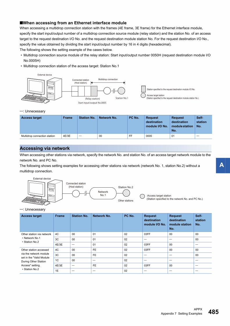
APPXAppendix 7 Setting Examples 485
A
■When accessing from an Ethernet interface moduleWhen accessing a multidrop connection station with the frames (4E frame, 3E frame) for the Ethernet interface module,
specify the start input/output number of a multidrop connection source module (relay station) and the station No. of an access
target to the request destination I/O No. and the request destination module station No. For the request destination I/O No.,
specify the value obtained by dividing the start input/output number by 16 in 4 digits (hexadecimal).
The following shows the setting example of the cases below.
• Multidrop connection source module of the relay station: Start input/output number 0050H (request destination module I/O
No.0005H)
• Multidrop connection station of the access target: Station No.1
: Unnecessary
Accessing via networkWhen accessing other stations via network, specify the network No. and station No. of an access target network module to the
network No. and PC No.
The following shows setting examples for accessing other stations via network (network No. 1, station No.2) without a
multidrop connection.
: Unnecessary
Access target Frame Station No. Network No. PC No. Request destination module I/O No.
Request destination module station No.
Self-station No.
Multidrop connection station 4E/3E 00 FF 0005 01
Access target Frame Station No. Network No. PC No. Request destination module I/O No.
Request destination module station No.
Self-station No.
Other station via network
• Network No.1
• Station No.2
4C 00 01 02 03FF 00 00
3C 00 01 02 00
4E/3E 01 02 03FF 00
Other station accessed
via the network module
set in the "Valid Module
During Other Station
Access" setting.
• Station No.2
4C 00 FE 02 03FF 00 00
3C 00 FE 02 00
1C 00 02
4E/3E FE 02 03FF 00
1E 02
E71 C24
External device
Multidrop connectionConnected station(Host station)
:Station specified to the request destination module I/O No.
:Access target station(Station specified to the request destination module station No.)Station No.1
Start input/output No.0005(Relay station)
NetworkNo.1 :Access target station
(Station specified to the network No. and PC No.)Other stations
External device
Connected station(Host station) Station No.2

486APPXAppendix 7 Setting Examples
Connecting with a multidrop link and via networkThe following shows setting examples for connecting with a multidrop connection and via network.
■Other stations via network from a multidrop connectionSpecify the setting for a multidrop connection including the connected station (host station) and the setting for a connection
via network each.
Specify the station No. of a multidrop connection station for a relay to the station No.
Specify the network No. and station No. of an access target to the network No. and PC No.
The following shows the setting example of the cases below.
• Multidrop connection station of the relay station: Station No.1
• Network module of the access target: Network No.1, station No.2
: Unnecessary
■Multidrop connection station via networkFor accessing a multidrop connection station in the target via network, specify the start input/output number of a multidrop
connection source module and the station No. of an access target to the request destination module I/O No. and the request
destination module station No. For the request destination module I/O No., specify the value obtained by dividing the start
input/output number by 16 in 4 digits (hexadecimal).
Specify the network No. and station No. of a network module for a relay station to the network No. and PC No.
The following shows the setting example of the cases below.
• Network module for the relay station: Network No.1, station No.2
• Multidrop connection source module of the relay station: Start input/output number 0050H (request destination module I/O
No.0005H)
• Multidrop connection station of the access target: Station No.1
: Unnecessary
Access target Frame Station No. Network No. PC No. Request destination module I/O No.
Request destination module station No.
Self-station No.
Other stations via
network from a multidrop
connection
4C 01 01 02 03FF 00 00
3C 01 01 02 00
Access target Frame Station No. Network No. PC No. Request destination module I/O No.
Request destination module station No.
Self-station No.
Multidrop connection
station via network
4C 00 01 02 0005 01 00
4E/3E 01 02 0005 01
External device Multidrop connection
Other stations
Network No.1
(Relay station)Connected station(Host station)
:Station specified to the station No.
:Access target station(Station specified to the network No. and PC No.)
Station No.2Station No.1
External deviceMultidrop connectionConnected station
(Host station)
NetworkNo.1 :Station specified to the request
destination module I/O No.
(Relay station)
:Access target station(Station specified to the request destination module station No.)
:Station specified to the network No. and PC No.
Station No.2
Station No.1Start
input/output No.0005

APPXAppendix 7 Setting Examples 487
A
MEMO

488
INDEX
0 to 9
1C frame . . . . . . . . . . . . . . . . . . . . . . . . . . . 28,471E frame . . . . . . . . . . . . . . . . . . . . . . . . . . . 40,492C frame . . . . . . . . . . . . . . . . . . . . . . . . . . . 28,463C frame . . . . . . . . . . . . . . . . . . . . . . . . . . . 28,463E frame . . . . . . . . . . . . . . . . . . . . . . . . . . . 40,484C frame . . . . . . . . . . . . . . . . . . . . . . . . . . . 28,454E frame . . . . . . . . . . . . . . . . . . . . . . . . . . . 40,48
A
Accessible module . . . . . . . . . . . . . . . . . . . . . . 20Accessible range . . . . . . . . . . . . . . . . . . . . . . . 20ACPU monitoring timer . . . . . . . . . . . . . . . . . . 392Additional code . . . . . . . . . . . . . . . . . . . . . . . . . 35ASCII code. . . . . . . . . . . . . . . . . . . . . . . . . . 28,39
B
Binary code . . . . . . . . . . . . . . . . . . . . . . . . . 28,39Buffer memory . . . . . . . . . . . . . . . . . 150,381,430
C
Clear error information. . . . . . . . . . . . . . . . . . . 185Cluster . . . . . . . . . . . . . . . . . . . . . . . . . . . . . . 287Command . . . . . . . . . . . . . . . . . . . . . . . . . . . . 60Command list . . . . . . . . . . . . . . . . . . . . . . . . . . 60Connected station (host station) . . . . . . . . . . . . . 15Control code. . . . . . . . . . . . . . . . . . . . . . . . . . . 34
D
Device . . . . . . . . . . . . . . . . . . . . . . 15,65,348,395Device code . . . . . . . . . . . . . . . . . . . . 66,349,395Device extension specification . . . . . . . . . . . . . 436Drive memory . . . . . . . . . . . . . . . . . . . . . . . . . 287
E
Error code . . . . . . . . . . . . . . . . . . . . . . . . . 38,346Error information . . . . . . . . . . . . . . . . . . . . . . . . 44Extended file register. . . . . . . . . . . . . . . . . 369,416
F
File . . . . . . . . . . . . . . . . . . . . . . . . . . . . . 188,295Format. . . . . . . . . . . . . . . . . . . . . . . . . . . . . . . 28Format 1 . . . . . . . . . . . . . . . . . . . . . . . . . . . . . 29Format 2 . . . . . . . . . . . . . . . . . . . . . . . . . . . . . 30Format 3 . . . . . . . . . . . . . . . . . . . . . . . . . . . . . 31Format 4 . . . . . . . . . . . . . . . . . . . . . . . . . . . . . 32Format 5 . . . . . . . . . . . . . . . . . . . . . . . . . . . . . 33Frame . . . . . . . . . . . . . . . . . . . . . . . . . . . . . 28,40Frame ID No. . . . . . . . . . . . . . . . . . . . . . . . . . . 36
G
Global function . . . . . . . . . . . . . . . . . . . . . . . . 253
H
Header . . . . . . . . . . . . . . . . . . . . . . . . . . . . . . .42
I
Index modification. . . . . . . . . . . . . . . . . . . . . . .444Intelligent function module . . . . . . . . . . . . . . . . .156
K
Keyword . . . . . . . . . . . . . . . . . . . . . . . . . . . . .288
L
Label. . . . . . . . . . . . . . . . . . . . . . . . . . . . . . . .123LED OFF . . . . . . . . . . . . . . . . . . . . . . . . . 185,187Link device. . . . . . . . . . . . . . . . . . . . . . . . . . . . .15Loopback test. . . . . . . . . . . . . . . . . . . . . . 183,387
M
Message format . . . . . . . . . . . . . . . . . . . . . . 29,41Mode switching function . . . . . . . . . . . . . . . . . .257Monitoring timer . . . . . . . . . . . . . . . . . . . . . . . . .43Multiple CPU systems . . . . . . . . . . . . . . . . . . . .460
N
Network No. . . . . . . . . . . . . . . . . . . . . . . . . . . . .52Number of processing per one communication. . .464
O
On-demand function . . . . . . . . . . . . . . . . . . . . .278Online program change. . . . . . . . . . . . . . . . . . .462Other station . . . . . . . . . . . . . . . . . . . . . . . . . . .15
P
Password. . . . . . . . . . . . . . . . . . . . . . . . . . . . .193PC No. . . . . . . . . . . . . . . . . . . . . . . . . . . . 52,391Processing time . . . . . . . . . . . . . . . . . . . . . . . .452Processing timing of CPU module . . . . . . . . . . . .23Programmable controller CPU monitoring function . . . . . . . . . . . . . . . . . . . . . . . . . . . . . .264
R
Relay station . . . . . . . . . . . . . . . . . . . . . . . . . . .15Remote operation . . . . . . . . . . . . . . . . . . . . . . .171Remote password. . . . . . . . . . . . . . . . . . . . . . .178Request destination module I/O number . . . . . . . .55Request destination module station No. . . . . . . . .55Request message. . . . . . . . . . . . . . . . . . . . . . . .15Response message . . . . . . . . . . . . . . . . . . . . . .15
S
Self-station No.. . . . . . . . . . . . . . . . . . . . . . . . . .58Serial communication function . . . . . . . . . . . 21,459Serial number. . . . . . . . . . . . . . . . . . . . . . . . . . .42

489
I
Special function module. . . . . . . . . . . . . . . 381,430Station No. . . . . . . . . . . . . . . . . . . . . . . . . . . . . 50Subheader . . . . . . . . . . . . . . . . . . . . . . . . . . . . 42Sum check code . . . . . . . . . . . . . . . . . . . . . . . . 36
T
Transmission sequence initialization function . . . 256Transmission time when accessing other stations . . . . . . . . . . . . . . . . . . . . . . . . . . . . . 454
U
User frame . . . . . . . . . . . . . . . . . . . . . . . . . . . 244

490
REVISIONS*The manual number is given on the bottom left of the back cover.
Japanese manual number: SH-080003-AD
1999 MITSUBISHI ELECTRIC CORPORATION
Revision date *Manual number Description
December 1999
to
July 2013
SH(NA)-080008-A
to
SH(NA)-080008-S
Due to the transition to the e-Manual, the details of revision have been deleted.
June 2014 SH(NA)-080008-T Complete revision (layout change)
Added models
RJ71C24, RJ71C24-R2, RJ71C24-R4
July 2014 SH(NA)-080008-U Minor correction.
August 2015 SH(NA)-080008-V Added or modified parts
Section 6.2, Section 8.1, Section 8.2, Section 8.3, Section 8.4, Section 8.5, Chapter 9, Section 12.4,
Appendix 7
May 2016 SH(NA)-080008-W Added or modified parts
Section 3.2, Section 6.2, Section 8.1, Section 8.2, Section 8.3, Section 8.4, Chapter 9, Section 11.1,
Section 12.4, Appendix 6
November 2017 SH(NA)-080008-X Added or modified parts
DISCONTINUED MODELS, Section 8.2, Section 11.1
This manual confers no industrial property rights or any rights of any other kind, nor does it confer any patent licenses. Mitsubishi Electric Corporation cannot
be held responsible for any problems involving industrial property rights which may occur as a result of using the contents noted in this manual.

491
WARRANTYPlease confirm the following product warranty details before using this product.
1. Gratis Warranty Term and Gratis Warranty RangeIf any faults or defects (hereinafter "Failure") found to be the responsibility of Mitsubishi occurs during use of the product within the gratis warranty term, the product shall be repaired at no cost via the sales representative or Mitsubishi Service Company.However, if repairs are required onsite at domestic or overseas location, expenses to send an engineer will be solely at the customer's discretion. Mitsubishi shall not be held responsible for any re-commissioning, maintenance, or testing on-site that involves replacement of the failed module.[Gratis Warranty Term]The gratis warranty term of the product shall be for one year after the date of purchase or delivery to a designated place.Note that after manufacture and shipment from Mitsubishi, the maximum distribution period shall be six (6) months, and the longest gratis warranty term after manufacturing shall be eighteen (18) months. The gratis warranty term of repair parts shall not exceed the gratis warranty term before repairs.[Gratis Warranty Range](1) The range shall be limited to normal use within the usage state, usage methods and usage environment, etc., which
follow the conditions and precautions, etc., given in the instruction manual, user's manual and caution labels on the product.
(2) Even within the gratis warranty term, repairs shall be charged for in the following cases.1. Failure occurring from inappropriate storage or handling, carelessness or negligence by the user. Failure caused
by the user's hardware or software design.2. Failure caused by unapproved modifications, etc., to the product by the user.3. When the Mitsubishi product is assembled into a user's device, Failure that could have been avoided if functions
or structures, judged as necessary in the legal safety measures the user's device is subject to or as necessary by industry standards, had been provided.
4. Failure that could have been avoided if consumable parts (battery, backlight, fuse, etc.) designated in the instruction manual had been correctly serviced or replaced.
5. Failure caused by external irresistible forces such as fires or abnormal voltages, and Failure caused by force majeure such as earthquakes, lightning, wind and water damage.
6. Failure caused by reasons unpredictable by scientific technology standards at time of shipment from Mitsubishi.7. Any other failure found not to be the responsibility of Mitsubishi or that admitted not to be so by the user.
2. Onerous repair term after discontinuation of production(1) Mitsubishi shall accept onerous product repairs for seven (7) years after production of the product is discontinued.
Discontinuation of production shall be notified with Mitsubishi Technical Bulletins, etc.(2) Product supply (including repair parts) is not available after production is discontinued.
3. Overseas serviceOverseas, repairs shall be accepted by Mitsubishi's local overseas FA Center. Note that the repair conditions at each FA Center may differ.
4. Exclusion of loss in opportunity and secondary loss from warranty liabilityRegardless of the gratis warranty term, Mitsubishi shall not be liable for compensation to:(1) Damages caused by any cause found not to be the responsibility of Mitsubishi.(2) Loss in opportunity, lost profits incurred to the user by Failures of Mitsubishi products.(3) Special damages and secondary damages whether foreseeable or not, compensation for accidents, and
compensation for damages to products other than Mitsubishi products.(4) Replacement by the user, maintenance of on-site equipment, start-up test run and other tasks.
5. Changes in product specificationsThe specifications given in the catalogs, manuals or technical documents are subject to change without prior notice.

492
TRADEMARKSEthernet is a registered trademark of Fuji Xerox Co., Ltd. in Japan.
Unicode is either a registered trademark or a trademark of Unicode, Inc. in the United States and other countries.
The company names, system names and product names mentioned in this manual are either registered trademarks or
trademarks of their respective companies.
In some cases, trademark symbols such as '' or '' are not specified in this manual.


SH(NA)-080008-X(1711)KWIX
MODEL: MC-PROTOCOL-R-E
MODEL CODE: 13JF89
Specifications subject to change without notice.
When exported from Japan, this manual does not require application to theMinistry of Economy, Trade and Industry for service transaction permission.
HEAD OFFICE : TOKYO BUILDING, 2-7-3 MARUNOUCHI, CHIYODA-KU, TOKYO 100-8310, JAPANNAGOYA WORKS : 1-14 , YADA-MINAMI 5-CHOME , HIGASHI-KU, NAGOYA , JAPAN