Embed Size (px)
Citation preview

MRCTMegger Relay and Current Transformer Test Set
■■ Industry leading test duration using patented simultaneous multi-tap measurements reduces testing time by 20% on multi-tap CT’s
■■ Accuracy to support testing of metering and protection class CT
■■ Integrated single phase relay test system
■■ Grouped testing: demagnetization, knee points, ratios, saturation curves, winding resistance insulation and more
■■ Measure all ratio’s and saturation curves on multi-tap CT’s with one lead connection
■■ Optional DC excitation technique for testing CTs with kneepoints up to 30 kV
■■ Optional Integrated VT/CVT test system
DESCRIPTIONThe Megger MRCT is a light weight, robust, portable unit used to perform demagnetization, ratio, saturation, winding resistance, polarity, phase deviation, and insulation tests on current transformers. The MRCT automatically calculates ratio errors, saturation curves, and knee points. The MRCT provides a microprocessor-controlled variable voltage and current output and precision instrumentation for automatically testing single and multi ratio CTs, reducing testing time and increasing productivity. The MRCT will directly connect to multi ratio CT’s and perform all tests – saturation, ratio and polarity, winding resistance and insulation – on all taps with the push of a button and without changing leads.
The MRCT can be controlled via Megger’s Smart Touch View Interface (STVI) controller. The STVI controller is a full color, high resolution, LCD touch screen which allows the user to perform manual and automatic testing quickly and easily using the manual test screen, as well as using pre-constructed test routines. The large color display permits the user to easily read all pertinent data while the test is being performed and provides the ability to view the current transformer’s saturation curve. The unit can also be configured to come without a Megger STVI and can be controlled via a laptop with Megger’s PowerDB software.
MRCTMegger Relay and Current Transformer Test Set
Current transformers can be tested in their equipment configuration, such as being mounted in transformers, oil circuit breakers or switchgear. It is necessary for the equipment to be completely isolated from the electrical system prior to testing.
APPLICATIONSSaturation TestWith the single push of a button, the MRCT performs a CT saturation test and calculates the rated knee point. The saturation test can be performed at frequency of 50 or 60 Hz up to 2,000 volts as required by IEC regulations. In addition the MRCT can be configured to test kneepoints up to 30 kV using an alternative DC technique. This allows testing the majority of CTs using line frequency while still being able to test larger generation class CT with a portable instrument.
The MRCT will calculate the rated knee point in compliance with either IEEE C57.13.1, IEC 60044-1, IEC 60044-6 or IEC 61869 on both standards as well as of specialized CTs such as PX, TPS, TPX, TPY and TPZ. While the saturation test is being performed, the MCRT will plot the CT saturation curve on the STVI display and automatically provide the user with the rated knee point per the desired IEEE or IEC standard. Many substations CTs include a multi-ratio secondary; therefore the MRCT has the ability to plot and simultaneously display up to 10 CT saturation curves.
MRCTMegger Relay and Current Transformer Test Set
2
Ratio, Polarity Test Ratio testing can be performed by using the MRCT. The method used by the MRCT compares a voltage applied to the secondary winding to the resulting voltage produced on the primary winding. For example, if 1 volt per turn is applied to the secondary winding, the voltage present on the primary winding would be 1 volt. More specifically, if 120 volts were applied to the secondary of a 600:5 current transformer (120:1 ratio), 1 volt would be present on the primary winding.
Winding Resistance Test Measures CT winding resistance with the injection of a test voltage, measuring the DC current and calculating temperature compensated resistance.
Demagnetization Normal operating conditions and typical winding resistance measurements can cause a CT to become magnetized. The MRCT has the ability to automatically demagnetize the CT under test. This automatic demagnetization routine is useful to ensure that the CT saturation test yield correct results. Prior to testing demagnetization is recommended per both ANSI and IEC standards.
CT BurdenThe MRCT measures the connected CT burden load with direct injection of secondary current to a load that is disconnected from the CT. The MRCT measures the secondary voltage in magnitude and angle of the connected burden in VA and power factor.
Insulation Resistance TestIn order to ensure that the CT secondary wiring is properly insulated, the MRCT system includes a 500 V, 1,000 V insulation resistance test system. This test ensures that the CT secondary winding and secondary wiring is properly insulated per both ANSI and IEC standards.
The MRCT will also automatically switch the test leads to perform all required insulation test. These test include H-L, H-G, L-G.
Note: Disconnect all electronic loads before performing this test.
Data Storage and PrintingThe MRCT test system not only permits accurate and automated CT testing, but also catalogs and stores test results within the STVI for simple retrieval by software at a later date. All cataloged test results can be uploaded to Megger’s PowerDBTM Lite for report generation and saturation curve plotting on a computer or STVI. PowerDB Lite also has the ability to operate the MRCT with no operator intervention, thus providing a completely computer controlled automated test system.
UpgradeabilityThe MRCT includes the ability to upgrade testing capability. With various configurations and accessories the MRCT system can be upgraded as new testing needs are developed.
FEATURES AND BENEFITS■■ Industry leading test duration using patented simultaneous multi tap measurements - The MRCT system can provide concurrent measurement of voltages on all taps during CT saturation, and ratio and polarity testing. This allows the MRCT system to calculate the knee points and ratios of all windings at the same time thus eliminating the need for multiple tests on a CT. This will drastically reduce testing time.
■■ Automated Test Plans with CT Saturation, Ratio and Polarity, Winding Resistance and Insulation Testing - The microprocessor controlled output fully automates testing of CTs. The MRCT will directly connect to multi ratio CTs and perform all tests – saturation, ratio and polarity, winding resistance, and insulation – on all taps with the push of a button and without changing leads.
■■ Direct Connection to Multi Ratio CTs - The MRCT will directly connect to all taps on multi ratio CTs to eliminate lead changes required to test all inner-winding CT ratios, saturation curves and knee points. The MRCT will test all programmed taps with the push of one button.
■■ Full Color, High Resolution, LCD Touch Screen - Menu screens and touch screen function buttons are provided to quickly and easily select the desired test function. Tests results can be saved to the unit for download to a memory stick to transfer or print test reports.
■■ CT Saturation, Ratio and Polarity, Winding Resistance, and Insulation Automated Testing - The microprocessor-controlled output fully automates testing of CTs. This automated testing simplifies CT testing and reduces testing time. Automated testing is accomplished directly on the Megger’s STVI or via PowerDB Lite.
■■ CT Demagnetization - During operation and routine DC winding resistance testing, it is possible for a CT to become magnetized. The MRCT includes an automated CT demagnetization function, which allows determination of accurate knee point and ratios thus providing stable, repeatable test results, and reduces test time.
■■ Insulation Test - The MRCT includes a 500/1,000 V insulation test system to verify the CT secondary winding and secondary wiring. This insures that the secondary insulation has not degraded and will continue to perform its function during high current faults.
■■ Test Result Report - The MRCT offers storage of complete test files in an easy-to-use, versatile format that permits upload to PowerDB Lite, or printing test results using the optional external printer. These options provide a simple, complete, easy way to store over 200 test results and saturation curves. All test results can be cataloged and stored in the MRCT.
The MRCT is available in 2 onboard display/enclosure options.

MRCTMegger Relay and Current Transformer Test Set
3
SPECIFICATIONS
Input 100 to 132 V or 200 to 264 V, 1ø, 50 or 60 Hz, 15 A max.
Output
Voltage Continuously variable in three ranges: 0 to 30 V at 5.0 A max (15 minute on, 5 minute off) 0 to 300 V at 1.0 A max (15 minute on, 5 minute off) 300 to 2000 V at 1.0 A max (5 minute on, 5 minute off)
Current
Output Current Power Max V/Duty Cycle
30 Amperes 200 VA (282 peak) 6.67 V rms (15 minutes on, 5 minutes off)
60 Amperes 600 VA 90 cycles
Instrumentation
Voltmeters
Output
Resolution 0.0000 to 1.9999/19.999/199.99/1999.9
Ranges 0 to 2/20/200/2000 V
Accuracy ±0.5% of reading typical±1.0% of reading typical max
Input
Primary Voltage Measurement
Ranges 0 to 0.35/2.0/20.0/200.0/600.0 V
Resolution 0.0001 to 1.9999/19.999/199.9/600 V
Accuracy ±0.02% of reading and ±.02% range typical
±0.05% of reading and ±05% range maximum
Secondary Voltage Measurement
Ranges 0 to 2/20.0/200.0/2000.0 V
Resolution 0.0000 to 19.999/199.9/1999.9 V
Accuracy 0 to 999.9 V ±0.02% of reading and ±.02% range typical ±0.05% of reading and ±.05% range maximum1000 to 2000 V ±0.08% of reading and ±.08% range typical ±0.2% of reading and ±0.2% range maximum
Ammeter
Output
Ranges 0.0 to 1.0/10.0/60.0 A
Resolution .001/.01
Input
Excitation curve testing
Range 0.0000 to 0.1/1.0/8.0 A
Accuracy ±0.08% of reading ±.08% range typical ±0.2% of reading ±0.2% range maximum
Phase Angle Measurement
3 digits
Range 0 to 360 degrees
Resolution 1 minute
Accuracy ±3 minuntes typical ±6 minutes maximum
Ratio Test
Secondary Voltage Injection Method
Range Accuracy
0.8 to 2000 ±0.02% typical ±0.05% maximum
2000 to 5000 ±0.03% typical ±0.1% maximum
5000 to 20000 ±0.05% typical ±0.2% maximum
Winding Resistance Test
Measuring Range 0 – 30 Ω
Accuracy (at 20° C) ±1%, 0 – 30 Ω
Insulation Test
Test Voltage 1000 VDC, 500 VDC
Measuring Range 20 GΩ, 10 GΩ
Short Circuit Current 1.5 mA nominal
Test Current on Load 1 mA at min. pass values of insulation (as specified in BS7671, HD 384 and IEC 364)
Accuracy 1000 volts ±3% ±2 digits ±0.2% per GΩ 500 volts ±3% ±2 digits ±0.4% per GΩ
Communication Interfaces
Ethernet
Environment
Humidity Relative humidity 5%...95% not condensing
Operating -10º C to 50º C
Storage -30º C to 70º C
Enclosure The unit is housed in a rugged enclosure suitable for use in outdoor substations.
Standards IEC 61010, CSA 22.2, CE
Input Power 100 to 240 V (±10%) AC, 50/60 Hz
Dimensions 14” H X 7.5” W X 12” D (36 H X 19.3 W X 30.5 D cm)
Weight 36.7 lb (16.7 kg)
CE Marking Low voltage directive 2006/95/EC
Electronmagnetic Compatibility Directive 2004/108/EC
Conformance Standards Safety
EN 61010-1 2010EN 61010-2-030 2010EN 61010-031 2002EN 61010 +A1
EMC EN 61326-1 2006EN 61326-2-1 2006
MRCTMegger Relay and Current Transformer Test Set
4
DESCRIPTIONS OF HARDWARE OPTIONS AND
ACCESSORIES
CURRENT TRANSFORMER TESTING (CT) USING DC VOLTAGE OPTION
DESCRIPTION
The MRCT can be configured to include the functionality to perform the excitation test on current transformers using DC voltage. With this configuration the MRCT can measure knee points on current transformers up to 30 kV. When the MRCT is configured to test in AC mode, the unit will perform the saturation test using AC voltage up to 2 kV. If the CT requires additional voltage above 2 kV to saturate, the MRCT will switch to DC voltage and complete the saturation of the CT. The MRCT will then convert the DC data to its AC equivalent and combine both sets of data into one excitation curve representing of the CT. On the other hand, if the MRCT is set to perform the excitation/saturation test using primarily DC voltage, then the MRCT will apply AC voltage up to 300V and then switch to DC voltage to finish saturating the CT. Again this data set will be combined and converted to line frequency either 50/60 Hz and a representative excitation curve created.
APPLICATIONS
As part of a regular maintenance program to verify factory readings and locate the presence of defects in current transformers, the MRCT can accurately perform the excitation test on CTs and measure the knee point up to 2 kV using AC voltage. For CTs that have a knee point higher than 2 kV the MRCT can be configured to utilize DC voltage to saturate the CT and accurately measure the knee point up to 30 kV.
DC VOLTAGE TESTING OPTION SPECIFICATIONS
CT Testing Using DC Voltage
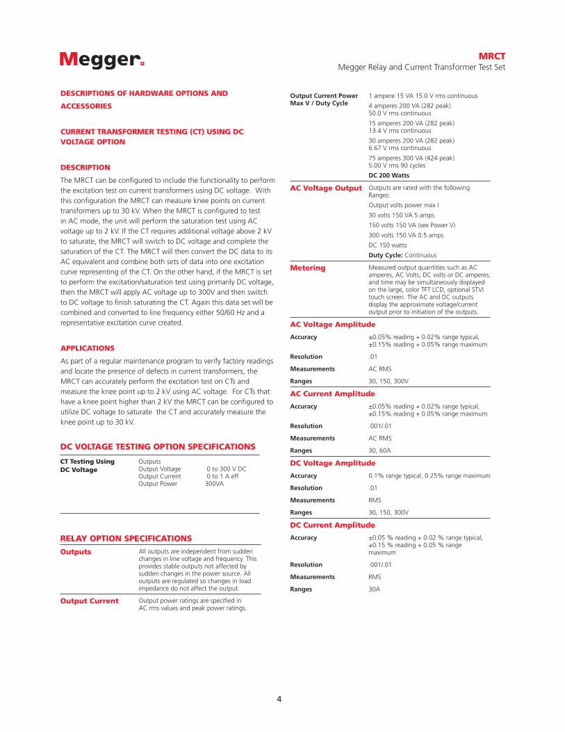
OutputsOutput Voltage 0 to 300 V DCOutput Current 0 to 1 A effOutput Power 300VA
RELAY OPTION SPECIFICATIONS
Outputs All outputs are independent from sudden changes in line voltage and frequency. This provides stable outputs not affected by sudden changes in the power source. All outputs are regulated so changes in load impedance do not affect the output.
Output Current Output power ratings are specified in AC rms values and peak power ratings.
Output Current Power Max V / Duty Cycle
1 ampere 15 VA 15.0 V rms continuous
4 amperes 200 VA (282 peak) 50.0 V rms continuous
15 amperes 200 VA (282 peak) 13.4 V rms continuous
30 amperes 200 VA (282 peak) 6.67 V rms continuous
75 amperes 300 VA (424 peak) 5.00 V rms 90 cycles
DC 200 Watts
AC Voltage Output Outputs are rated with the following Ranges:
Output volts power max I
30 volts 150 VA 5 amps
150 volts 150 VA (see Power V)
300 volts 150 VA 0.5 amps
DC 150 watts
Duty Cycle: Continuous
Metering Measured output quantities such as AC amperes, AC Volts, DC volts or DC amperes, and time may be simultaneously displayed on the large, color TFT LCD, optional STVI touch screen. The AC and DC outputs display the approximate voltage/current output prior to initiation of the outputs.
AC Voltage Amplitude
Accuracy ±0.05% reading + 0.02% range typical, ±0.15% reading + 0.05% range maximum
Resolution .01
Measurements AC RMS
Ranges 30, 150, 300V
AC Current Amplitude
Accuracy ±0.05% reading + 0.02% range typical, ±0.15% reading + 0.05% range maximum
Resolution .001/.01
Measurements AC RMS
Ranges 30, 60A
DC Voltage Amplitude
Accuracy 0.1% range typical, 0.25% range maximum
Resolution .01
Measurements RMS
Ranges 30, 150, 300V
DC Current Amplitude
Accuracy ±0.05 % reading + 0.02 % range typical, ±0.15 % reading + 0.05 % range maximum
Resolution .001/.01
Measurements RMS
Ranges 30A
MRCTMegger Relay and Current Transformer Test Set
5
DESCRIPTIONS OF HARDWARE OPTIONS AND ACCESSORIES
VOLTAGE TRANSFORMER (VT) TESTING OPTION
DESCRIPTION
The MRCT can be configured to include the functionality to test voltage transformers. With this configuration the MRCT can measure ratio errors and phase angles as well as the secondary winding resistance of inductive voltage transformers.
APPLICATIONS
As part of a regular maintenance program to verify factory readings and locate the presence of defects in voltage transformers, the MRCT can accurately measure the ratio, phase displacement, and secondary winding resistance. The MRCT utilizes up to 300V to accurately measure the ratio and phase angle of inductive voltage transformers.
COUPLING CAPACITOR VOLTAGE TRANSFORMER (CCVT) TESTING OPTION
DESCRIPTION
With the VT & CCVT testing option enabled the MRCT can measure the CCVT ratio and phase error. With an output of up to 2 kV the MRCT can measure a CCVT ratio error and phase error of low to medium voltage capacitive coupled voltage transformers up to 245 kV.
APPLICATIONS
The MRCT has ability to measure CCVT ratio and phase thus ensuring that the CCVT is working properly and can be returned to service. The MRCT the capability to supply up to 2000V to measure the ratio of low to medium voltage capacitive voltage transformers up to 245 kV.
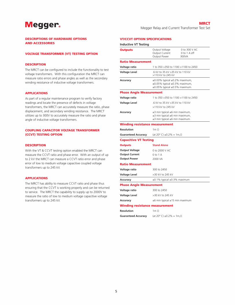
VT/CCVT OPTION SPECIFICATIONS
Inductive VT Testing
Outputs Output Voltage 0 to 300 V ACOutput Current 0 to 1 A effOutput Power 300VA
Ratio Measurement
Voltage ratio 1 to 350 >350 to 1100 >1100 to 2450
Voltage Level .6 kV to 35 kV >35 kV to 110 kV >110 kV to 245 kV
Accuracy ±0.03% typical ±0.2% maximum, ±0.05% typical ±0.3% maximum,±0.05% typical ±0.5% maximum.
Phase Angle Measurement
Voltage ratio 1 to 350 >350 to 1100 >1100 to 2450
Voltage Level .6 kV to 35 kV >35 kV to 110 kV
>110 kV to 245 kV
Accuracy ±3 min typical ±6 min maximum, ±3 min typical ±6 min maximum, ±3 min typical ±6 min maximum.
Winding resistance measurement
Resolution 1m Ω
Guaranteed Accuracy (at 20° C) ±0.2% + 1m,Ω
Capacitive VT Testing
Outputs
Output Voltage
Output Current
Output Power
Stand Alone
0 to 2000 V AC
0 to 1 A
2000 VA
Ratio Measurement
Voltage ratio 300 to 2450
Voltage Level >30 kV to 245 kV
Accuracy ±0.1% typical ±0.3% maximum
Phase Angle Measurement
Voltage ratio 300 to 2450
Voltage Level >30 kV to 245 kV
Accuracy ±6 min typical ±15 min maximum
Winding resistance measurement
Resolution 1m Ω
Guaranteed Accuracy (at 20° C) ±0.2% + 1m,Ω
MRCTMegger Relay and Current Transformer Test Set
6
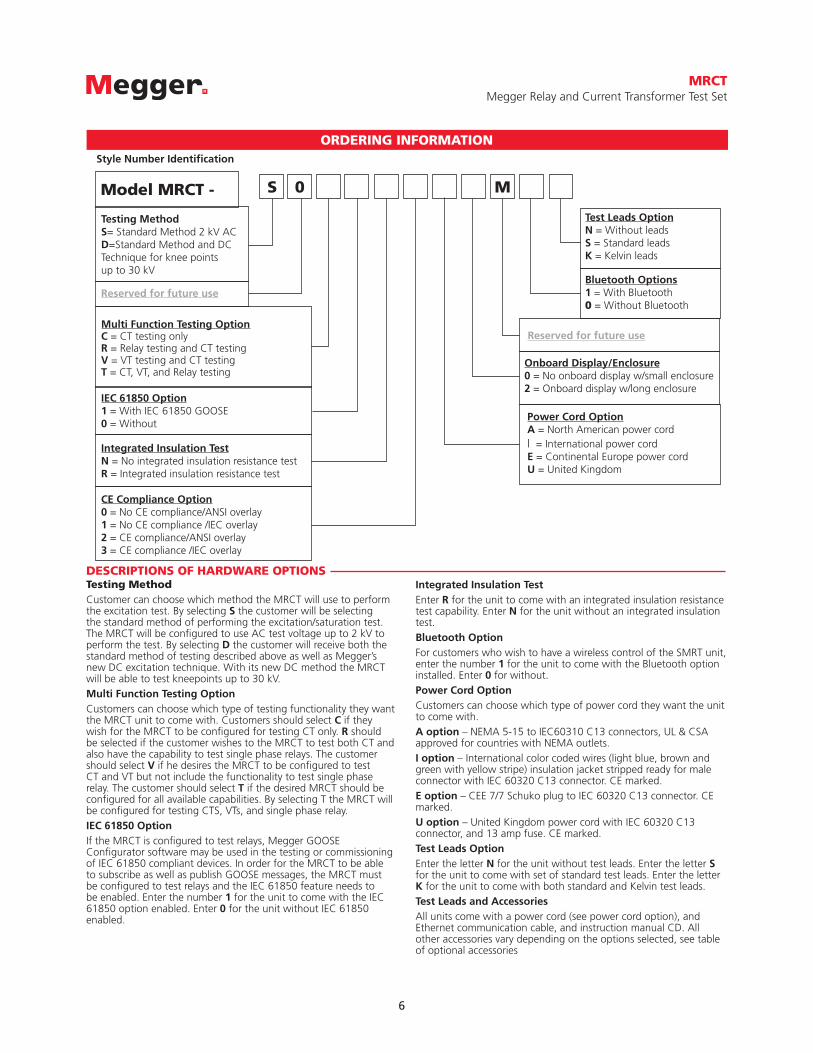
DESCRIPTIONS OF HARDWARE OPTIONSTesting MethodCustomer can choose which method the MRCT will use to perform the excitation test. By selecting S the customer will be selecting the standard method of performing the excitation/saturation test. The MRCT will be configured to use AC test voltage up to 2 kV to perform the test. By selecting D the customer will receive both the standard method of testing described above as well as Megger’s new DC excitation technique. With its new DC method the MRCT will be able to test kneepoints up to 30 kV.Multi Function Testing OptionCustomers can choose which type of testing functionality they want the MRCT unit to come with. Customers should select C if they wish for the MRCT to be configured for testing CT only. R should be selected if the customer wishes to the MRCT to test both CT and also have the capability to test single phase relays. The customer should select V if he desires the MRCT to be configured to test CT and VT but not include the functionality to test single phase relay. The customer should select T if the desired MRCT should be configured for all available capabilities. By selecting T the MRCT will be configured for testing CTS, VTs, and single phase relay.IEC 61850 OptionIf the MRCT is configured to test relays, Megger GOOSE Configurator software may be used in the testing or commissioning of IEC 61850 compliant devices. In order for the MRCT to be able to subscribe as well as publish GOOSE messages, the MRCT must be configured to test relays and the IEC 61850 feature needs to be enabled. Enter the number 1 for the unit to come with the IEC 61850 option enabled. Enter 0 for the unit without IEC 61850 enabled.
ORDERING INFORMATION
Model MRCT -
Testing MethodS= Standard Method 2 kV ACD=Standard Method and DC Technique for knee points up to 30 kV
Multi Function Testing OptionC = CT testing onlyR = Relay testing and CT testingV = VT testing and CT testingT = CT, VT, and Relay testing
Integrated Insulation TestN = No integrated insulation resistance testR = Integrated insulation resistance test
CE Compliance Option0 = No CE compliance/ANSI overlay1 = No CE compliance /IEC overlay2 = CE compliance/ANSI overlay3 = CE compliance /IEC overlay
Onboard Display/Enclosure0 = No onboard display w/small enclosure2 = Onboard display w/long enclosure
Test Leads OptionN = Without leads S = Standard leadsK = Kelvin leads
Bluetooth Options1 = With Bluetooth0 = Without Bluetooth
IEC 61850 Option1 = With IEC 61850 GOOSE 0 = Without
Power Cord OptionA = North American power cord I = International power cord E = Continental Europe power cordU = United Kingdom
0 MS
Style Number Identification
Reserved for future use
Reserved for future use
Integrated Insulation TestEnter R for the unit to come with an integrated insulation resistance test capability. Enter N for the unit without an integrated insulation test.Bluetooth OptionFor customers who wish to have a wireless control of the SMRT unit, enter the number 1 for the unit to come with the Bluetooth option installed. Enter 0 for without.Power Cord OptionCustomers can choose which type of power cord they want the unit to come with. A option – NEMA 5-15 to IEC60310 C13 connectors, UL & CSA approved for countries with NEMA outlets.I option – International color coded wires (light blue, brown and green with yellow stripe) insulation jacket stripped ready for male connector with IEC 60320 C13 connector. CE marked.E option – CEE 7/7 Schuko plug to IEC 60320 C13 connector. CE marked.U option – United Kingdom power cord with IEC 60320 C13 connector, and 13 amp fuse. CE marked.Test Leads OptionEnter the letter N for the unit without test leads. Enter the letter S for the unit to come with set of standard test leads. Enter the letter K for the unit to come with both standard and Kelvin test leads.Test Leads and AccessoriesAll units come with a power cord (see power cord option), and Ethernet communication cable, and instruction manual CD. All other accessories vary depending on the options selected, see table of optional accessories

MRCTMegger Relay and Current Transformer Test Set
7
TEST LEADS AND ACCESSORIES All units come with a power cord, an Ethernet communication cable, and instruction manual. All other accessories varies depending on the features selected, see Table of Accessories.
Included Standard Accessories
Description Part Number
Power Cord - Depending on the style number, the unit will come with one of the following,
Line cord, North American 90015-267
Line cord, Continental Europe with CEE 7/7 Schuko Plug 90015-268
Line cord, International color coded wire 90015-269
Line cord, United Kingdom 90015-270
Ethernet cable for interconnection to PC, 210cm (7 ft.) long (Qty. 1 ea) 90003-594
Instruction manual 81757
2003-724
9004-427
830029
Ground lead (1 each)
Alligator clip (5 each)
USB memory stick (1 each)
green with yellow, with large ground clip, 20 ft
Black, 4.1mm
640266
Large test clip (1 each)
red, 40mm opening
640267Large test clip (1 each)
black, 40mm opening
1005-466
684005
Set of primary test leads (1 each)
Cable/Spade lug adapter (small, 5 each)
(H1, H2) Test Leads, 20ft (6.096m)
Small lug fit most new relay small terminal blocks. Lug adapter, black, 4.1 mm, rated up to 1000 V/ 20 Amps CAT II
Accessory Carry Case (1 each)
Cable/Spade lug adapter (small, 5 each)
Use to carry power cord, Ethernet cable, Optional STVI and test leads.
Small lug fit most new relay small terminal blocks. Lug adapter, red, 4.1 mm, rated up to 1000 V/ 20 Amps CAT II
2003-725
684004
1005-774
9005-599
Set of secondary test leads (1 each)
Screw in banana test jack (5 each)
5 Tap ( X1, X2, X3, X4, X5) Test Leads, 20ft (6.096m)
TABLE OF ACCESSORIES
STANDARD LEADS
Accessories are supplied with the selection of the various features depending upon the option selected . Test Leads and Accessories can also be ordered individually, see below for accessories included with option and part numbers.
Accessories included in standard set of test leads.
90015-267
90015-268
90015-270
United States4271 Bronze WayDallas, Texas 75237-1088 USAT 800.723.2861 (USA only)T +1 214.333.3201F +1 214.331.7399E [email protected]
MRCT_DS_EN_V07
www.megger.comISO 9001:2008The word ‘Megger’ is a registered trademark
MRCTMegger Relay and Current Transformer Test Set
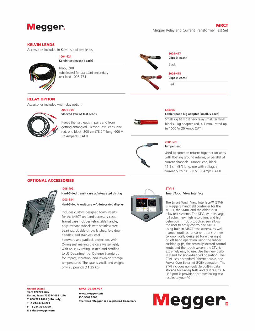
2001-394Sleeved Pair of Test Leads:
Keeps the test leads in pairs and from getting entangled. Sleeved Test Leads, one red, one black, 200 cm (78.7”) long, 600 V, 32 Amperes CAT II
1004-424
2001-573
2005-477
2005-478
Kelvin test leads (1 each)
Jumper lead
Clips (1 each)
Clips (1 each)
black, 20ftsubstituted for standard secondary test lead 1005-774
Used to common returns together on units with floating ground returns, or parallel of current channels. Jumper lead, black, 12.5 cm (5”) long, use with voltage / current outputs, 600 V, 32 Amps CAT II
Black
Red
KELVIN LEADS
RELAY OPTION
OPTIONAL ACCESSORIES
Accessories included in Kelvin set of test leads.
Accessories included with relay option.
Cable/Spade lug adapter (small, 5 each)
Small lug fit most new relay small terminal blocks. Lug adapter, red, 4.1 mm, rated up to 1000 V/ 20 Amps CAT II
684004
Includes custom designed foam inserts for the MRCT unit and accessory case. Transit case includes retractable handle, polyurethane wheels with stainless steel bearings, double-throw latches, fold down handles, and stainless steelhardware and padlock protection, withO-ring seal making the case water-tight,with an IP 67 rating. Tested and certified to US Department of Defense Standards for impact, vibration, and low/high storage temperatures. The case is small, and weighs only 25 pounds (11.25 kg).
1006-492
1003-884
Hard-Sided transit case w/integrated display
Hard-Sided transit case w/o integrated display
STVI-1
Smart Touch View Interface
The Smart Touch View Interface™ (STVI) is Megger’s handheld controller for the MRCT, the SMRT and the older MPRT relay test systems. The STVI, with its large, full color, new high resolution, and high definition TFT LCD touch screen allows the user to easily control the MRCT using built in MRCT test screens, as well manual routines for current transformers. Ergonomically designed for either right or left hand operation using the rubber cushion grips, the centrally located control knob, and the touch screen, the STVI is extremely easy to use. Use the new built-in stand for single-handed operation. The STVI uses a standard Ethernet cable, and Power Over Ethernet (POE) operation. The STVI includes non-volatile built-in data storage for saving tests and test results. A USB port is provided for transferring test results to your PC.