Embed Size (px)
Citation preview
ICAS 2002 CONGRESS
1105.1
Keywords: CFD capability based on block-structured and hybrid meshes, industrial applications
Abstract
Some years ago the national CFD projectMEGAFLOW was initiated in Germany, whichcombines many of the CFD developmentactivities from DLR, universities and aircraftindustry. Its goal is the development andvalidation of a dependable and efficientnumerical tool for the aerodynamic simulationof complete aircraft. The MEGAFLOW softwaresystem includes the block-structured Navier-Stokes code FLOWer and the unstructuredNavier-Stokes code TAU. Both codes havereached a high level of maturity and they arebeing intensively used by the German aerospaceindustry in the design process of a new aircraft.This paper highlights recent improvements andenhancements of the software. Its capability topredict viscous flows around complex industrialapplications for transport aircraft design isdemonstrated.
1 Introduction
Aerospace industry is increasingly relying onadvanced numerical simulation tools in the earlyaircraft design phase. Nevertheless, there is stilla great need for improvement of numericalmethods, because standards for simulationaccuracy and efficiency are constantly rising inindustrial applications. Moreover, it is crucial toreduce the response time for complexsimulations, although the relevant geometriesand underlying physical flow models arebecoming increasingly complicated.
In order to meet the requirements of Germanaircraft industry, the national projectMEGAFLOW was initiated some years agounder the leadership of DLR [1],[2]. The main
goal was to focus and direct developmentactivities carried out in industry, DLR anduniversities towards industrial needs. The closecollaboration between the partners led to thedevelopment and validation of a commonaerodynamic simulation system providing botha structured and an unstructured predictioncapability for complex applications. Thesoftware is constantly updated to meet therequirements of industrial implementations.
In the first phase of the project the mainemphasis was put on the improvement andenhancement of the block-structured gridgenerator MegaCads and the Navier-Stokessolver FLOWer. In a second phase the activitieswere focused on the development of theunstructured/hybrid Navier-Stokes solver TAU.Due to a comprehensive and cooperativevalidation effort and quality controlled softwaredevelopment processes, both flow solvers havereached a high level of maturity and reliability.The MEGAFLOW software is used in theGerman aeronautic industry and researchorganizations for a wide range of applications.Due to the use of common software, the processof transferring latest research and technologyresults into production codes has beenconsiderably accelerated.
The present paper describes the features ofthe software and demonstrates its capability onthe basis of several applications from civilaircraft design.
2 MEGAFLOW Software
The MEGAFLOW software offers flowprediction capabilities which are based on bothblock-structured and hybrid meshes.
MEGAFLOW – A NUMERICAL FLOW SIMULATIONTOOL FOR TRANSPORT AIRCRAFT DESIGN
N. Kroll 1, C.C. Rossow 1, D. Schwamborn 1, K. Becker 2, G. Heller 3
1 DLR, Institute of Aerodynamics and Flow Technology, 38108 Braunschweig, Germany,2 Airbus-Deutschland GmbH, 28183-Bremen, Germany
3 Fairchild-Dornier GmbH, 82234 Weßling, Germany
Kroll, N., Rossow, C.C., Schwamborn, D., Becker, K., Heller, G.
1105.2
2.1 Grid Generation
For the generation of block-structured gridsthe interactive system MegaCads has beendeveloped. Specific features of the tool are theparametric construction of multi-block gridswith arbitrary grid topology, generation ofhigh-quality grids through advanced elliptic andparabolic grid generation techniques,construction of overlapping grids and batchfunctionality for efficient integration in anautomatic optimization loop for aerodynamicshape design. Details of the software are givenin [3]. The limitation of MegaCads is the nonautomatic definition of the block topologywhich for rather complex configurations mayresult in a time consuming and labor intensivegrid generation activity. Besides MegaCads, thecommercial software package ICEM-HEXAand specialized in-house codes [4] are beingused for specific applications.
In contrast to the block-structured approach,no major development activities have beendevoted to the generation of unstructuredmeshes within the MEGAFLOW project. Astrategic cooperation, however, has beenestablished with the company CentaurSoft [5]which provides the hybrid grid generationpackage Centaur. The software consists of threemajor parts. An interactive program reads in theCAD data of the geometry under consideration,performs some CAD cleaning if necessary andsets up the grid generation process. In a secondstep the surface and volume grid are generatedautomatically. For viscous calculations a quasi-structured prismatic cell layer with a specifiednumber of cells around the geometry surfaceensures high resolution of boundary layereffects. In a third step grid adaptation may beused to locally refine grid resolution. During thecooperation the Centaur grid generationsoftware has been substantially advanced fortransport aircraft applications. Improvementsinclude for example the generation of nonisotropic elements and wake surfaces.
2.2 Flow Solvers
The main components of the MEGAFLOWsoftware are the block-structured flow solver
FLOWer and the unstructured hybrid flowsolver TAU. Both codes solve the compressible,three-dimensional Reynolds-averaged Navier-Stokes equations for rigid bodies in arbitrarymotion. The motion is taken into account bytransformation of the governing equations. Forthe simulation of aeroelastic phenomena bothcodes have been extended to allow geometryand mesh deformation [6]. For multidisciplinarysimulations the MPCCI-library [7] is used forthe data exchange between the mono-disciplinary codes. In the following sections thespecific features of the Navier-Stokes codes arebriefly described.
Block-Structured Navier-Stokes Code FLOWer
The FLOWer-Code is based on a finite-volume formulation on block-structured meshesusing either the cell vertex or the cell-centeredapproach. For the approximation of theconvective fluxes a central discretizationscheme combined with scalar or matrix artificialviscosity and several upwind discretizationschemes are available [8]. Integration in time isperformed using explicit multistage time-stepping schemes. For steady calculationsconvergence is accelerated by implicit residualsmoothing, local time stepping and multigrid.Preconditioning is used for low speed flows. Fortime accurate calculations an implicit timeintegration according to the dual time steppingapproach is employed. The code is highlyoptimized for vector computers. Parallelcomputations are based on MPI and they arerealized through the use of a high levelcommunication library [9].
A variety of turbulence models isimplemented in FLOWer, ranging from simplealgebraic eddy viscosity models over one- andtwo-equation models up to algebraic stressmodels. The Wilcox k-ω model is the standardmodel in FLOWer which is used for all types ofapplications. However, for transonic flow thelinearized algebraic stress model LEA [10]recently has shown superior behavior withrespect to other models [13]. All two-equationmodels can be combined with Kok’smodification [11] for improved prediction of

1105.3
MEGAFLOW – A NUMERICAL FLOW SIMULATION TOOL FORAIRCRAFT DESIGN
vortical flows. For supersonic flows differentcompressibility corrections are available.Recently the nonlinear EARSM of Wallin [12]has been implemented and is currently underinvestigation.
Besides the modeling accuracy for turbulentflows, the numerical robustness of therespective transport equation turbulence modelsfor complex applications has been a major issue.In FLOWer numerical stability is enhanced byan implicit treatment of the turbulence equationsand different limiting mechanisms that can beactivated by the user. The convergence behaviorof the FLOWer-Code for a rather complexapplication is demonstrated in Fig. 1. Results ofa viscous computation for a helicopter fuselageare shown [14]. The rotor is modeled through auniform actuator disc. The grid consists of 94blocks and 7 million grid points. The residualsfor density and turbulence quantities arereduced several orders of magnitude. In this lowMach number case the preconditioningtechnique has been employed.
Fig. 1 Viscous calculation for Dauphin helicopterfuselage at M∞=0.044, convergence behavior ofmass and k-ω turbulence equations.
The fully implicit integration of theturbulence equations also ensures efficientcalculations on highly stretched cells as theyappear in high Reynolds number flows. Fig. 2shows the convergence history of FLOWer forthe calculation of the viscous flow around theRAE 2822 airfoil at different Reynoldsnumbers. The advantage of the fully implicitmethod compared to the explicit multigridscheme with point implicit treatment of source
terms is evident.
Fig. 2 Effect of Reynolds number on convergence forthe RAE 2822 airfoil at M∞=0.73, α=2.80.
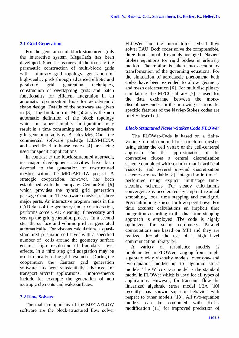
FLOWer is able to perform transitionprediction on airfoils using a module consistingof a laminar boundary layer code and an eN-database method based on linear stability theory[15]. Fig. 3 shows the predicted and measuredforce polars and transition locations of asubsonic laminar airfoil. This approachsubstantially improves the quality of predictedforce coefficients. The experimentallydetermined transition points are reproduced withhigh accuracy. The transition predictioncapability is currently extended to wings and 2Dhigh-lift systems.
An important feature of FLOWer is theChimera technique, which considerablyenhances the flexibility of the block-structuredapproach [16],[17]. This technique enables thegeneration of a grid around a complexconfiguration by decomposing the geometryinto less complex components. Separatecomponent grids are generated which overlapeach other and which are embedded in aCartesian background grid that covers thewhole computational domain. In combinationwith flexible meshes, the Chimera techniqueenables an efficient way to simulate bodies inrelative motion. The communication from meshto mesh is realized through interpolation in theoverlapping area. The search for cells which areused for interpolation is performed using analternating digital tree method. In the case when
Kroll, N., Rossow, C.C., Schwamborn, D., Becker, K., Heller, G.
1105.4
a mesh overlaps a body which lies insideanother mesh, hole cutting procedures have tobe used in order to exclude the invalid pointsfrom computation.
Fig. 3 Transition prediction with eN-database methodfor laminar Sommers airfoil at M∞=0.1 andRe=4x10⁶, (a) force polars calculated fullyturbulent and with transition, (b) computed andmeasured transition locations.
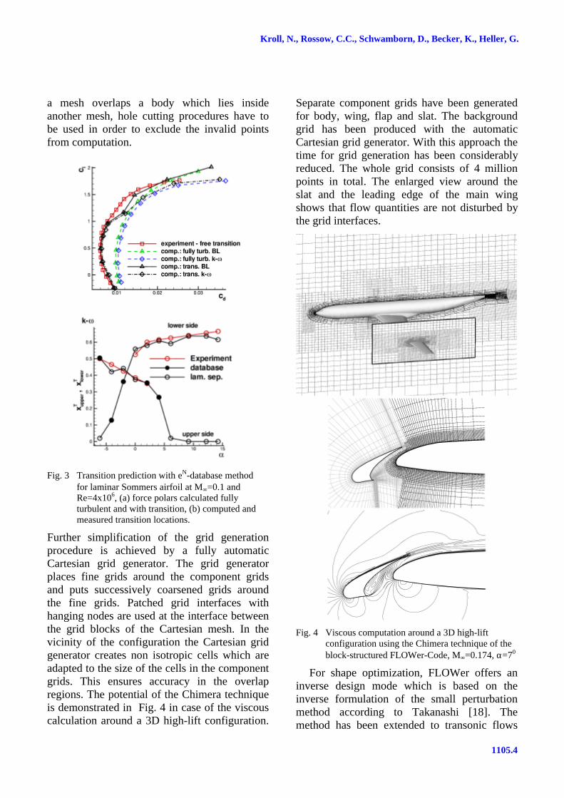
Further simplification of the grid generationprocedure is achieved by a fully automaticCartesian grid generator. The grid generatorplaces fine grids around the component gridsand puts successively coarsened grids aroundthe fine grids. Patched grid interfaces withhanging nodes are used at the interface betweenthe grid blocks of the Cartesian mesh. In thevicinity of the configuration the Cartesian gridgenerator creates non isotropic cells which areadapted to the size of the cells in the componentgrids. This ensures accuracy in the overlapregions. The potential of the Chimera techniqueis demonstrated in Fig. 4 in case of the viscouscalculation around a 3D high-lift configuration.
Separate component grids have been generatedfor body, wing, flap and slat. The backgroundgrid has been produced with the automaticCartesian grid generator. With this approach thetime for grid generation has been considerablyreduced. The whole grid consists of 4 millionpoints in total. The enlarged view around theslat and the leading edge of the main wingshows that flow quantities are not disturbed bythe grid interfaces.
Fig. 4 Viscous computation around a 3D high-liftconfiguration using the Chimera technique of theblock-structured FLOWer-Code, M∞=0.174, α=70
For shape optimization, FLOWer offers aninverse design mode which is based on theinverse formulation of the small perturbationmethod according to Takanashi [18]. Themethod has been extended to transonic flows
1105.5
MEGAFLOW – A NUMERICAL FLOW SIMULATION TOOL FORAIRCRAFT DESIGN
[19] and is capable of designing airfoils, wingsand nacelles in inviscid and viscous flows. Thisstrategy is very efficient, however, it isrestricted to a prescription of a target pressuredistribution. In order to support shapeoptimization based on more general costfunctions and constraints, the continuous adjointapproach based on the work of Jameson [20]has been implemented in FLOWer [21]. Withthe solution of the adjoint flow equations thegradients of the cost functions can be efficientlycalculated independent of the number of designvariables. Since the adjoint and flow equationsare solved in a similar way, all features of themain FLOWer-Code are available in the adjointsolver. Therefore, complex 3D multi-blockgeometries with arbitrary parametrization can behandled, as well as aerodynamic constraints andmulti-point designs. The adjoint approach iscurrently extended to the Navier-Stokesequations.
Hybrid Navier-Stokes Code TAU
The Navier-Stokes code TAU [22]makes use of the advantages of unstructuredgrids. The mesh may consist of a combinationof prismatic, pyramidal, tetrahedral andhexahedral cells and therefore combine theadvantages of regular grids for the accurateresolution of viscous shear layers in the vicinityof walls with the flexibility of grid generationtechniques for unstructured meshes. The use ofa dual mesh makes the solver independent of thetype of cells that the initial grid is composed of.Various spatial discretization schemes wereimplemented, including a central scheme withartificial dissipation and several upwindmethods. In order to accelerate convergence, amultigrid procedure was developed based on theagglomeration of the control volumes of thedual grid for coarse grid computations.
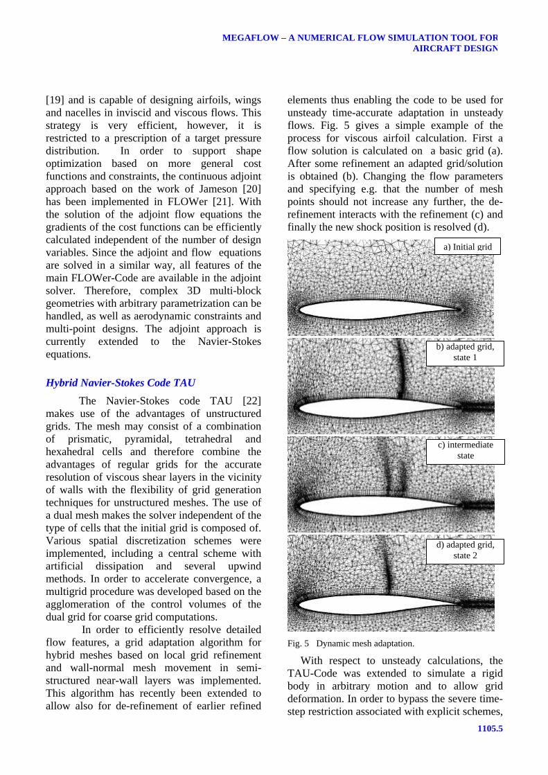
In order to efficiently resolve detailedflow features, a grid adaptation algorithm forhybrid meshes based on local grid refinementand wall-normal mesh movement in semi-structured near-wall layers was implemented.This algorithm has recently been extended toallow also for de-refinement of earlier refined
elements thus enabling the code to be used forunsteady time-accurate adaptation in unsteadyflows. Fig. 5 gives a simple example of theprocess for viscous airfoil calculation. First aflow solution is calculated on a basic grid (a).After some refinement an adapted grid/solutionis obtained (b). Changing the flow parametersand specifying e.g. that the number of meshpoints should not increase any further, the de-refinement interacts with the refinement (c) andfinally the new shock position is resolved (d).
Fig. 5 Dynamic mesh adaptation.
With respect to unsteady calculations, theTAU-Code was extended to simulate a rigidbody in arbitrary motion and to allow griddeformation. In order to bypass the severe time-step restriction associated with explicit schemes,
b) adapted grid,state 1
d) adapted grid,state 2
a) Initial grid
c) intermediatestate
Kroll, N., Rossow, C.C., Schwamborn, D., Becker, K., Heller, G.
1105.6
the implicit method based on the dual timestepping approach was implemented. For thecalculation of low-speed flows, preconditioningof the compressible flow equations similar tothe method used in FLOWer was implemented.One of the important features of the TAU-Codeis its high efficiency on parallel computers.Parallelization is based on the message passingconcept using the MPI-library [9]. The code isfurther optimized either for cache or vectorprocessors through specific edge coloringprocedures.
The standard turbulence model in TAUis the Spalart-Allmaras model with Edwardsmodification, yielding highly satisfactory resultsfor a wide range of applications while beingnumerically robust. Besides this model, anumber of different k-ω models with andwithout compressibility corrections areavailable. Also the linearized algebraic stressmodel LEA [10] has recently been integrated.
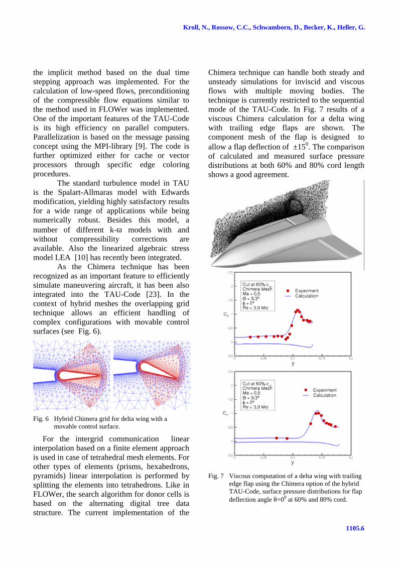
As the Chimera technique has beenrecognized as an important feature to efficientlysimulate maneuvering aircraft, it has been alsointegrated into the TAU-Code [23]. In thecontext of hybrid meshes the overlapping gridtechnique allows an efficient handling ofcomplex configurations with movable controlsurfaces (see Fig. 6).
Fig. 6 Hybrid Chimera grid for delta wing with amovable control surface.
For the intergrid communication linearinterpolation based on a finite element approachis used in case of tetrahedral mesh elements. Forother types of elements (prisms, hexahedrons,pyramids) linear interpolation is performed bysplitting the elements into tetrahedrons. Like inFLOWer, the search algorithm for donor cells isbased on the alternating digital tree datastructure. The current implementation of the
Chimera technique can handle both steady andunsteady simulations for inviscid and viscousflows with multiple moving bodies. Thetechnique is currently restricted to the sequentialmode of the TAU-Code. In Fig. 7 results of aviscous Chimera calculation for a delta wingwith trailing edge flaps are shown. Thecomponent mesh of the flap is designed toallow a flap deflection of ±150. The comparisonof calculated and measured surface pressuredistributions at both 60% and 80% cord lengthshows a good agreement.
Fig. 7 Viscous computation of a delta wing with trailingedge flap using the Chimera option of the hybridTAU-Code, surface pressure distributions for flapdeflection angle θ=00 at 60% and 80% cord.
1105.7
MEGAFLOW – A NUMERICAL FLOW SIMULATION TOOL FORAIRCRAFT DESIGN
3 Software Validation
Software validation is a central and criticalissue for providing reliable CFD tools forindustrial applications. Among others, thevalidation exercises should address consistencyof the numerical methods, accuracy assessmentfor different critical application cases andsensitivity studies with respect to numerical andphysical parameters. Best practicedocumentation is an essential part of the work.Over the last few years the MEGAFLOWsoftware was validated for a wide range ofconfigurations and flow conditions (see e.g.[2],[25],[26]). This section deals with recentresults for a subsonic and transonic validationtest case.
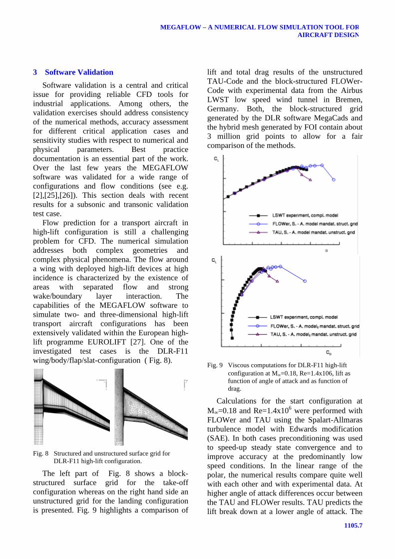
Flow prediction for a transport aircraft inhigh-lift configuration is still a challengingproblem for CFD. The numerical simulationaddresses both complex geometries andcomplex physical phenomena. The flow arounda wing with deployed high-lift devices at highincidence is characterized by the existence ofareas with separated flow and strongwake/boundary layer interaction. Thecapabilities of the MEGAFLOW software tosimulate two- and three-dimensional high-lifttransport aircraft configurations has beenextensively validated within the European high-lift programme EUROLIFT [27]. One of theinvestigated test cases is the DLR-F11wing/body/flap/slat-configuration ( Fig. 8).
Fig. 8 Structured and unstructured surface grid forDLR-F11 high-lift configuration.
The left part of Fig. 8 shows a block-structured surface grid for the take-offconfiguration whereas on the right hand side anunstructured grid for the landing configurationis presented. Fig. 9 highlights a comparison of
lift and total drag results of the unstructuredTAU-Code and the block-structured FLOWer-Code with experimental data from the AirbusLWST low speed wind tunnel in Bremen,Germany. Both, the block-structured gridgenerated by the DLR software MegaCads andthe hybrid mesh generated by FOI contain about3 million grid points to allow for a faircomparison of the methods.
Fig. 9 Viscous computations for DLR-F11 high-liftconfiguration at M∞=0.18, Re=1.4x10⁶, lift asfunction of angle of attack and as function ofdrag.
Calculations for the start configuration atM∞=0.18 and Re=1.4x10⁶ were performed withFLOWer and TAU using the Spalart-Allmarasturbulence model with Edwards modification(SAE). In both cases preconditioning was usedto speed-up steady state convergence and toimprove accuracy at the predominantly lowspeed conditions. In the linear range of thepolar, the numerical results compare quite wellwith each other and with experimental data. Athigher angle of attack differences occur betweenthe TAU and FLOWer results. TAU predicts thelift break down at a lower angle of attack. The

Kroll, N., Rossow, C.C., Schwamborn, D., Becker, K., Heller, G.
1105.8
lack of mesh resolution in the hybrid grid isconsidered to be the main reason for thisdifference.
In the framework of the AIAA CFD DragPrediction Workshop [24], the accuracy of theMEGAFLOW software was assessed to predictaerodynamic forces and moments for the DLR-F4 wing-body configuration [13]. In Fig. 10 liftcoefficient as function of drag and angle ofattack for Case 2 (M∞=0.75, Re=3x10⁶)calculated with FLOWer and TAU arepresented. These results were obtained usinggrids generated in-house at DLR. On request allcalculations were performed fully turbulent. TheFLOWer computations were carried out on agrid with 3.5 million points using centraldiscretization with a mixed scalar and matrixdissipation operator and the k/ω-LEAturbulence model. The TAU results are based onan initial grid containing 1.7 million pointswhich was adapted for each angle of attackyielding grids with 2.4 million points. Inaddition, an adaptation of the prismatic gridtowards Y+=1 was done. Central discretizationwith standard settings of artificial dissipationwas used. Turbulence was modeled with theone-equation model of Spalart-Allmaras. As canbe seen from Fig. 10 the fully turbulentFLOWer computations overpredict themeasured drag curve by approximately 20 dragcounts. Investigations have shown [13] thatinclusion of transition in the calculation reducesthe predicted drag by 14 drag counts, reducingthe overprediction of drag to approximately 6drag counts. The results of the unstructuredfully-turbulent computations with TAUperfectly match with the experimental data.However, as for the structured computations,hybrid calculations with transition setting willreduce the predicted level of drag, in this caseby approximately 10 drag-counts. Fig. 10 alsoshows the comparison of predicted andmeasured lift coefficient as a function of angleof attack. The values calculated by FLOWeragree very well with the experiment, whereasthe results obtained with TAU overpredict thelift almost in the whole range of angle of attack.
Fig. 10 Viscous calculations for DLR-F4 wing/bodyconfiguration (AIAA drag prediction workshop,case 2), CL(CD), CL(α).
For the pitching moment ( Fig. 11) the resultsobtained with FLOWer agree very well withexperimental data. This is due to the fact thatthe surface pressure distribution predicted withthe FLOWer-Code is in good agreement withthe experiment. In case of the hybrid TAU-Codethere are some discrepancies between thepredicted and measured surface pressuresresulting in a significant overprediction of thepitching moment. Further investigations [13]have shown that the improved results obtainedwith the FLOWer-Code are mainly attributed toa lower level of numerical dissipation(improved grid resolution and matrixdissipation) combined with the advanced 2-equation k/ω-LEA turbulence model.
1105.9
MEGAFLOW – A NUMERICAL FLOW SIMULATION TOOL FORAIRCRAFT DESIGN
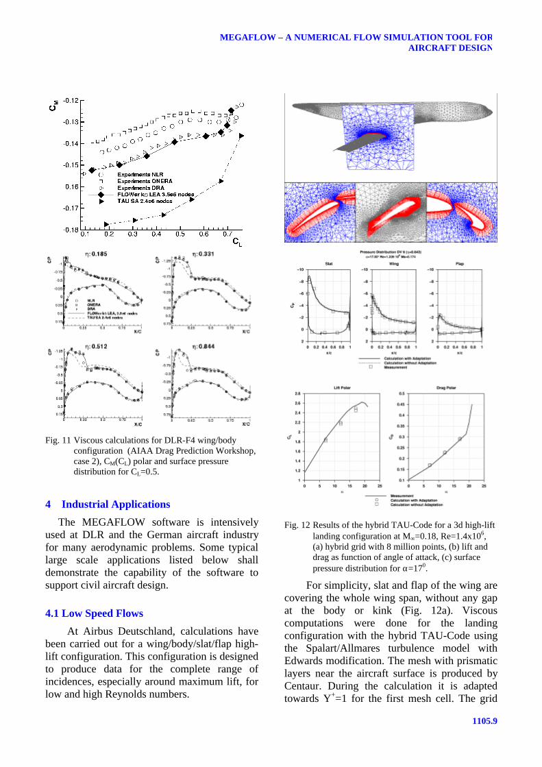
Fig. 11 Viscous calculations for DLR-F4 wing/bodyconfiguration (AIAA Drag Prediction Workshop,case 2), CM(CL) polar and surface pressuredistribution for CL=0.5.
4 Industrial Applications
The MEGAFLOW software is intensivelyused at DLR and the German aircraft industryfor many aerodynamic problems. Some typicallarge scale applications listed below shalldemonstrate the capability of the software tosupport civil aircraft design.
4.1 Low Speed Flows
At Airbus Deutschland, calculations havebeen carried out for a wing/body/slat/flap high-lift configuration. This configuration is designedto produce data for the complete range ofincidences, especially around maximum lift, forlow and high Reynolds numbers.
Fig. 12 Results of the hybrid TAU-Code for a 3d high-liftlanding configuration at M∞=0.18, Re=1.4x10⁶,(a) hybrid grid with 8 million points, (b) lift anddrag as function of angle of attack, (c) surfacepressure distribution for α=170.
For simplicity, slat and flap of the wing arecovering the whole wing span, without any gapat the body or kink (Fig. 12a). Viscouscomputations were done for the landingconfiguration with the hybrid TAU-Code usingthe Spalart/Allmares turbulence model withEdwards modification. The mesh with prismaticlayers near the aircraft surface is produced byCentaur. During the calculation it is adaptedtowards Y+=1 for the first mesh cell. The grid

Kroll, N., Rossow, C.C., Schwamborn, D., Becker, K., Heller, G.
1105.10
consists of 8 million points. Pressuredistributions for all three wing elements at angleof attack α=170 and the aerodynamic forcesshow an excellent agreement with experimentaldata Fig. 12. For these calculations 64 CPUs ofthe Hitachi SR8000 computer were used. Thecomputation time for one polar point was 17 h.
At DLR, effort is concentrated to explorethe applicability of the hybrid TAU-Code toconfigurations beyond wing/body [28].
Fig. 13 Viscous simulation of the ALVAST high-liftconfiguration with UHBR engine using TAU,(a) surface pressure distribution, (b) nacellevortex, (c) convergence history.
For the DLR ALVAST model equipped with anadvanced UHBR (Ultra High Bypass Ratio)engine, numerical simulations are focused oncomplex flow phenomena arising from theengine installation at high-lift conditions.Special attention is paid to possible reductionsof the maximum lift angle by means ofdominating three-dimensional effects due toengine installation. Fig. 13a displays thesurface pressure coefficient of the ALVASThigh-lift configuration with installed UHBRengine at an angle of attack of α=12° in take-offconditions. The computation was performed ona hybrid grid with 10 million points generatedby Centaur. In Fig. 13b the vortex sheddingfrom the inboard side of the nacelle is shown.The vortex originates from the rolling-up of theshear layer and it crosses the slat and the wingupper side. Using the computational data asinput in a recent wind tunnel campaign, thisvortex system could be identified with PIVvisualization. The research carried out in thiscontext led to an improvement in engineboundary conditions on hybrid meshes and to animproved applicability of low speedpreconditioning to complex configurations. Fig.13c shows the convergence history of thecomputation. Despite the high complexity of theflow, a satisfying convergence of the densityresidual of about four orders of magnitude isachieved.
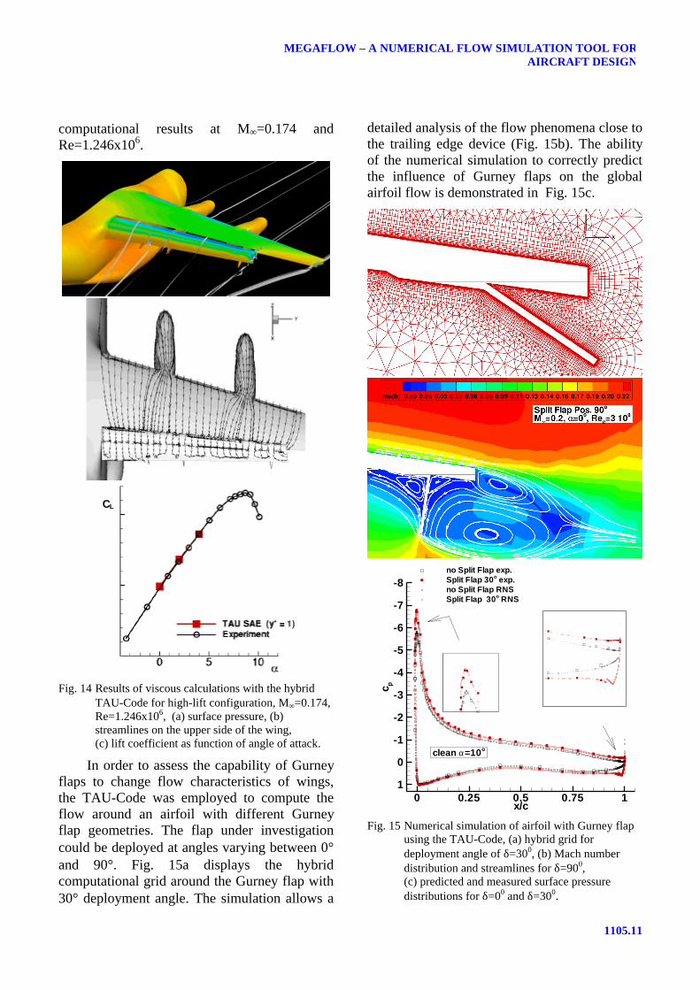
The applicability of the hybrid TAU-Codeto complex industrial configurations isdemonstrated for wing/body configurations withengine nacelles and deployed high-lift system(Fig. 14). Due to the double slotted flaps andcorresponding flap tracks, the geometry is quitecomplex. One of the objectives of thesecomputations was to identify the influence ofthe nacelles on the flow over the wing. In Fig.14b streamlines on the surface indicate stronginfluence already at an angle of attack of α=4°.The applicability of numerical simulation tosuch geometrically and physically complexconfigurations can be assessed from Fig. 14cwhere a comparison of lift as a function of angleof a attack is shown for experimental and
1105.11
MEGAFLOW – A NUMERICAL FLOW SIMULATION TOOL FORAIRCRAFT DESIGN
computational results at M∞=0.174 andRe=1.246x10⁶.
CL
Fig. 14 Results of viscous calculations with the hybridTAU-Code for high-lift configuration, M∞=0.174,Re=1.246x10⁶, (a) surface pressure, (b)streamlines on the upper side of the wing,(c) lift coefficient as function of angle of attack.
In order to assess the capability of Gurneyflaps to change flow characteristics of wings,the TAU-Code was employed to compute theflow around an airfoil with different Gurneyflap geometries. The flap under investigationcould be deployed at angles varying between 0°and 90°. Fig. 15a displays the hybridcomputational grid around the Gurney flap with30° deployment angle. The simulation allows a
detailed analysis of the flow phenomena close tothe trailing edge device (Fig. 15b). The abilityof the numerical simulation to correctly predictthe influence of Gurney flaps on the globalairfoil flow is demonstrated in Fig. 15c.
x/c
c p
0 0.25 0.5 0.75 1
-8
-7
-6
-5
-4
-3
-2
-1
0
1
no Split Flap exp.Split Flap 30o exp.no Split Flap RNSSplit Flap 30o RNS
clean α=10o
Fig. 15 Numerical simulation of airfoil with Gurney flapusing the TAU-Code, (a) hybrid grid fordeployment angle of δ=300, (b) Mach numberdistribution and streamlines for δ=900,(c) predicted and measured surface pressuredistributions for δ=00 and δ=300.
Kroll, N., Rossow, C.C., Schwamborn, D., Becker, K., Heller, G.
1105.12
Experimental and computational pressuredistributions are shown for Gurney flapdeployment angles of 0° and 30°. Note, thatdetails at the leading and trailing edge areconsistently predicted.
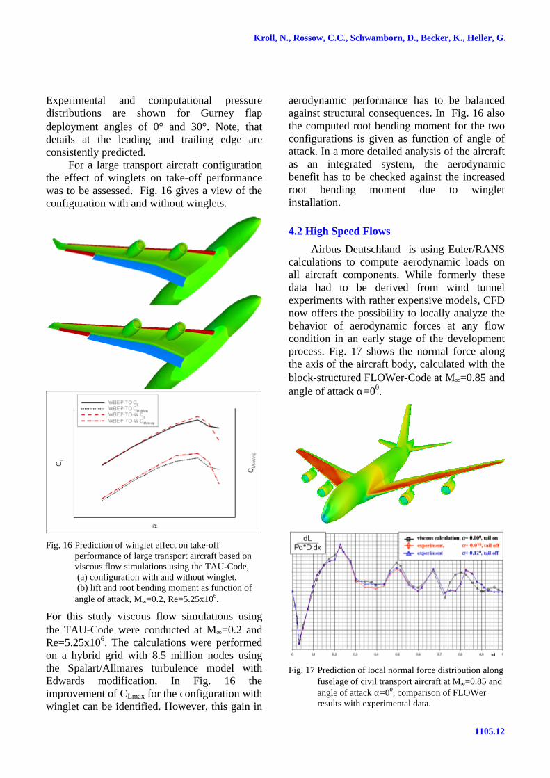
For a large transport aircraft configurationthe effect of winglets on take-off performancewas to be assessed. Fig. 16 gives a view of theconfiguration with and without winglets.
Fig. 16 Prediction of winglet effect on take-offperformance of large transport aircraft based onviscous flow simulations using the TAU-Code, (a) configuration with and without winglet, (b) lift and root bending moment as function ofangle of attack, M∞=0.2, Re=5.25x10⁶.
For this study viscous flow simulations usingthe TAU-Code were conducted at M∞=0.2 andRe=5.25x10⁶. The calculations were performedon a hybrid grid with 8.5 million nodes usingthe Spalart/Allmares turbulence model withEdwards modification. In Fig. 16 theimprovement of CLmax for the configuration withwinglet can be identified. However, this gain in
aerodynamic performance has to be balancedagainst structural consequences. In Fig. 16 alsothe computed root bending moment for the twoconfigurations is given as function of angle ofattack. In a more detailed analysis of the aircraftas an integrated system, the aerodynamicbenefit has to be checked against the increasedroot bending moment due to wingletinstallation.
4.2 High Speed Flows
Airbus Deutschland is using Euler/RANScalculations to compute aerodynamic loads onall aircraft components. While formerly thesedata had to be derived from wind tunnelexperiments with rather expensive models, CFDnow offers the possibility to locally analyze thebehavior of aerodynamic forces at any flowcondition in an early stage of the developmentprocess. Fig. 17 shows the normal force alongthe axis of the aircraft body, calculated with theblock-structured FLOWer-Code at M∞=0.85 andangle of attack α=00.
Fig. 17 Prediction of local normal force distribution alongfuselage of civil transport aircraft at M∞=0.85 andangle of attack α=00, comparison of FLOWerresults with experimental data.
1105.13
MEGAFLOW – A NUMERICAL FLOW SIMULATION TOOL FORAIRCRAFT DESIGN
The computation was performed on a grid with32 blocks and 8 million nodes. For comparisonexperimental results at nearby angles of attackare plotted. Major differences can only be seenin the rear fuselage area. The experiment wasconducted with tails off while the computationwas carried out with tails on.
One key issue during the design of anenhanced civil aircraft is the efficient engine-airframe integration. Modern very high-bypassratio engines and the corresponding closecoupling of engine and airframe may lead tosubstantial loss in lift and increased installationdrag.
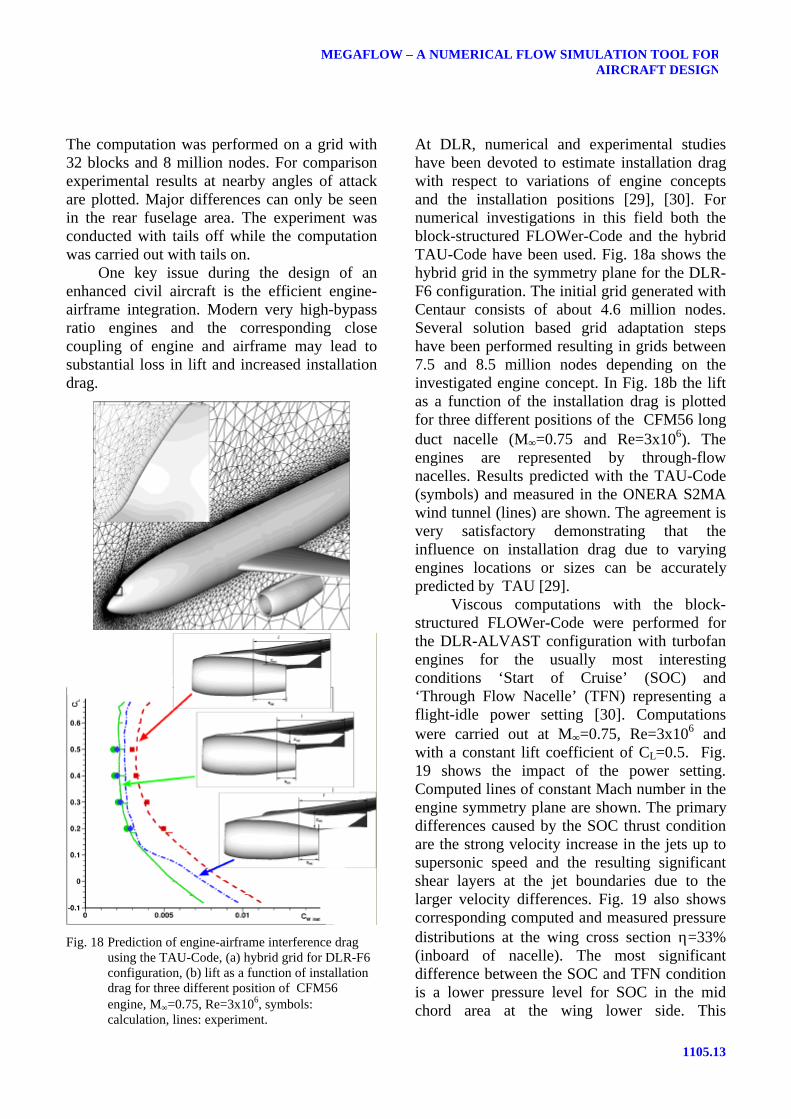
Fig. 18 Prediction of engine-airframe interference dragusing the TAU-Code, (a) hybrid grid for DLR-F6configuration, (b) lift as a function of installationdrag for three different position of CFM56engine, M∞=0.75, Re=3x10⁶, symbols:calculation, lines: experiment.
At DLR, numerical and experimental studieshave been devoted to estimate installation dragwith respect to variations of engine conceptsand the installation positions [29], [30]. Fornumerical investigations in this field both theblock-structured FLOWer-Code and the hybridTAU-Code have been used. Fig. 18a shows thehybrid grid in the symmetry plane for the DLR-F6 configuration. The initial grid generated withCentaur consists of about 4.6 million nodes.Several solution based grid adaptation stepshave been performed resulting in grids between7.5 and 8.5 million nodes depending on theinvestigated engine concept. In Fig. 18b the liftas a function of the installation drag is plottedfor three different positions of the CFM56 longduct nacelle (M∞=0.75 and Re=3x10⁶). Theengines are represented by through-flownacelles. Results predicted with the TAU-Code(symbols) and measured in the ONERA S2MAwind tunnel (lines) are shown. The agreement isvery satisfactory demonstrating that theinfluence on installation drag due to varyingengines locations or sizes can be accuratelypredicted by TAU [29].
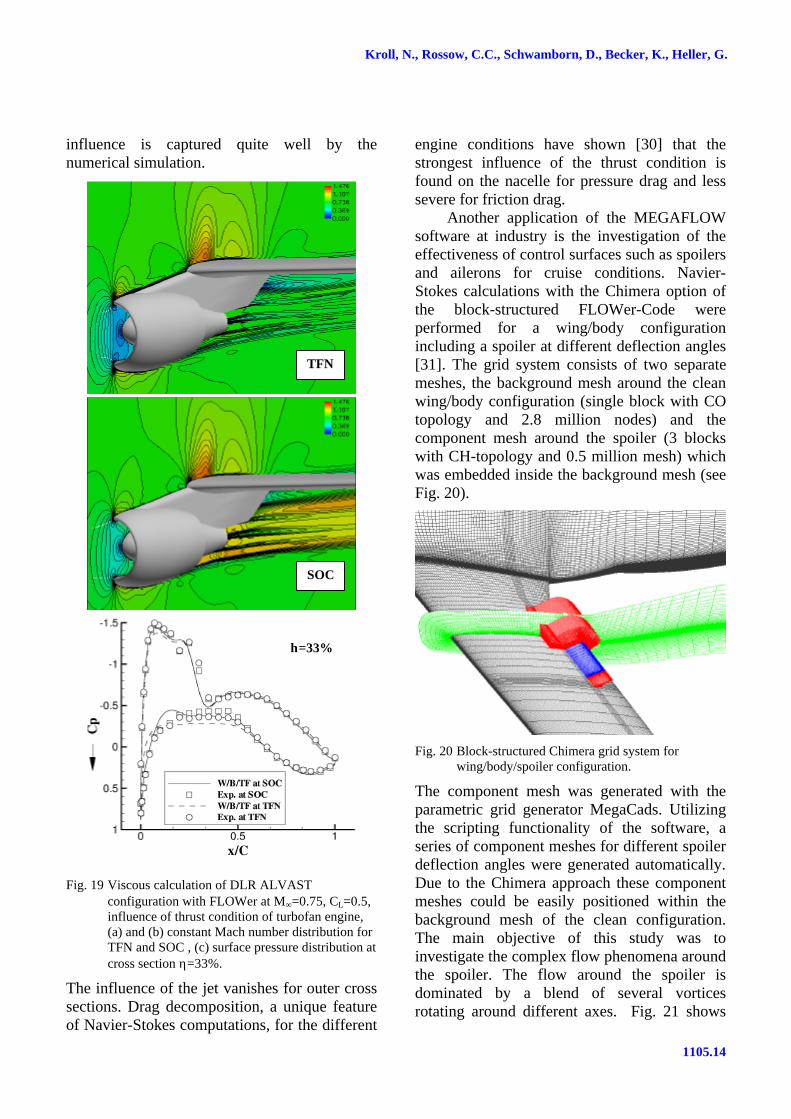
Viscous computations with the block-structured FLOWer-Code were performed forthe DLR-ALVAST configuration with turbofanengines for the usually most interestingconditions ‘Start of Cruise’ (SOC) and‘Through Flow Nacelle’ (TFN) representing aflight-idle power setting [30]. Computationswere carried out at M∞=0.75, Re=3x10⁶ andwith a constant lift coefficient of CL=0.5. Fig.19 shows the impact of the power setting.Computed lines of constant Mach number in theengine symmetry plane are shown. The primarydifferences caused by the SOC thrust conditionare the strong velocity increase in the jets up tosupersonic speed and the resulting significantshear layers at the jet boundaries due to thelarger velocity differences. Fig. 19 also showscorresponding computed and measured pressuredistributions at the wing cross section η=33%(inboard of nacelle). The most significantdifference between the SOC and TFN conditionis a lower pressure level for SOC in the midchord area at the wing lower side. This
Kroll, N., Rossow, C.C., Schwamborn, D., Becker, K., Heller, G.
1105.14
influence is captured quite well by thenumerical simulation.
Fig. 19 Viscous calculation of DLR ALVASTconfiguration with FLOWer at M∞=0.75, CL=0.5,influence of thrust condition of turbofan engine,(a) and (b) constant Mach number distribution forTFN and SOC , (c) surface pressure distribution atcross section η=33%.
The influence of the jet vanishes for outer crosssections. Drag decomposition, a unique featureof Navier-Stokes computations, for the different
engine conditions have shown [30] that thestrongest influence of the thrust condition isfound on the nacelle for pressure drag and lesssevere for friction drag.
Another application of the MEGAFLOWsoftware at industry is the investigation of theeffectiveness of control surfaces such as spoilersand ailerons for cruise conditions. Navier-Stokes calculations with the Chimera option ofthe block-structured FLOWer-Code wereperformed for a wing/body configurationincluding a spoiler at different deflection angles[31]. The grid system consists of two separatemeshes, the background mesh around the cleanwing/body configuration (single block with COtopology and 2.8 million nodes) and thecomponent mesh around the spoiler (3 blockswith CH-topology and 0.5 million mesh) whichwas embedded inside the background mesh (seeFig. 20).
Fig. 20 Block-structured Chimera grid system forwing/body/spoiler configuration.
The component mesh was generated with theparametric grid generator MegaCads. Utilizingthe scripting functionality of the software, aseries of component meshes for different spoilerdeflection angles were generated automatically.Due to the Chimera approach these componentmeshes could be easily positioned within thebackground mesh of the clean configuration.The main objective of this study was toinvestigate the complex flow phenomena aroundthe spoiler. The flow around the spoiler isdominated by a blend of several vorticesrotating around different axes. Fig. 21 shows
TFN
SOC
η=33%
1105.15
MEGAFLOW – A NUMERICAL FLOW SIMULATION TOOL FORAIRCRAFT DESIGN
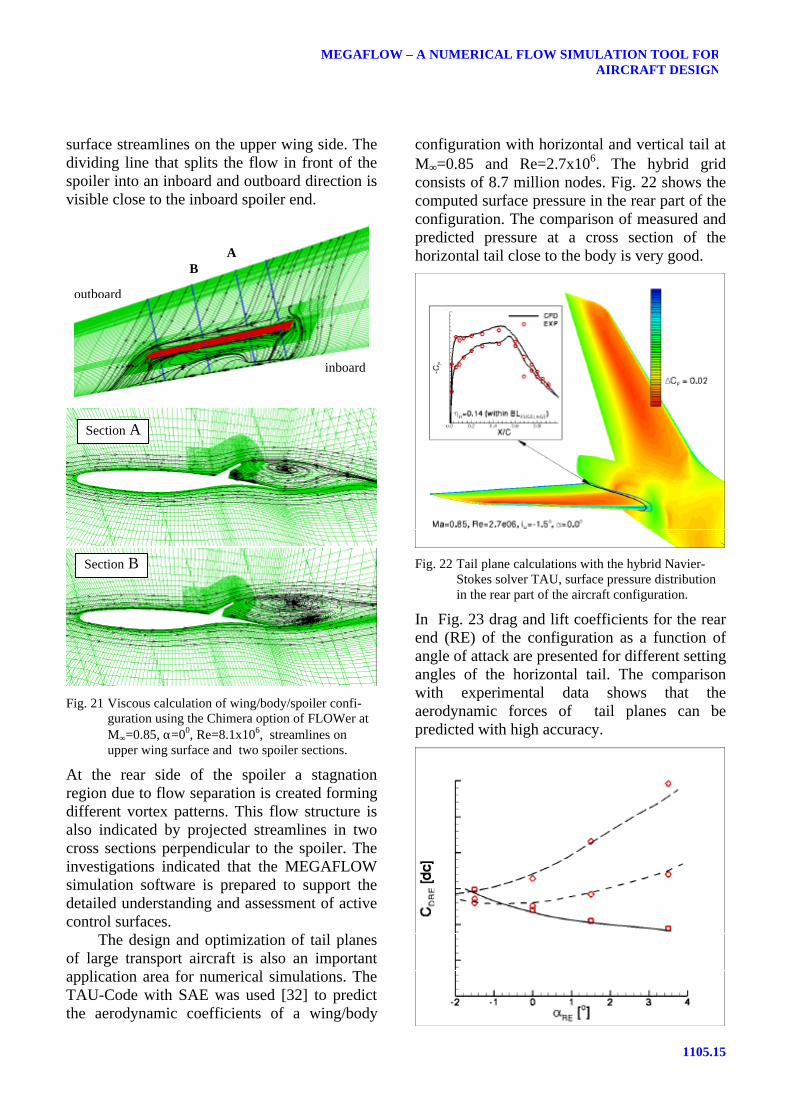
surface streamlines on the upper wing side. Thedividing line that splits the flow in front of thespoiler into an inboard and outboard direction isvisible close to the inboard spoiler end.
Fig. 21 Viscous calculation of wing/body/spoiler confi-guration using the Chimera option of FLOWer atM∞=0.85, α=00, Re=8.1x10⁶, streamlines onupper wing surface and two spoiler sections.
At the rear side of the spoiler a stagnationregion due to flow separation is created formingdifferent vortex patterns. This flow structure isalso indicated by projected streamlines in twocross sections perpendicular to the spoiler. Theinvestigations indicated that the MEGAFLOWsimulation software is prepared to support thedetailed understanding and assessment of activecontrol surfaces.
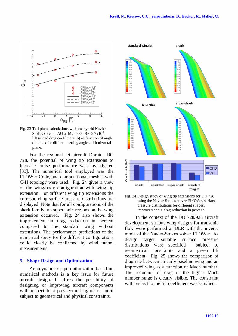
The design and optimization of tail planesof large transport aircraft is also an importantapplication area for numerical simulations. TheTAU-Code with SAE was used [32] to predictthe aerodynamic coefficients of a wing/body
configuration with horizontal and vertical tail atM∞=0.85 and Re=2.7x10⁶. The hybrid gridconsists of 8.7 million nodes. Fig. 22 shows thecomputed surface pressure in the rear part of theconfiguration. The comparison of measured andpredicted pressure at a cross section of thehorizontal tail close to the body is very good.
Fig. 22 Tail plane calculations with the hybrid Navier-Stokes solver TAU, surface pressure distributionin the rear part of the aircraft configuration.
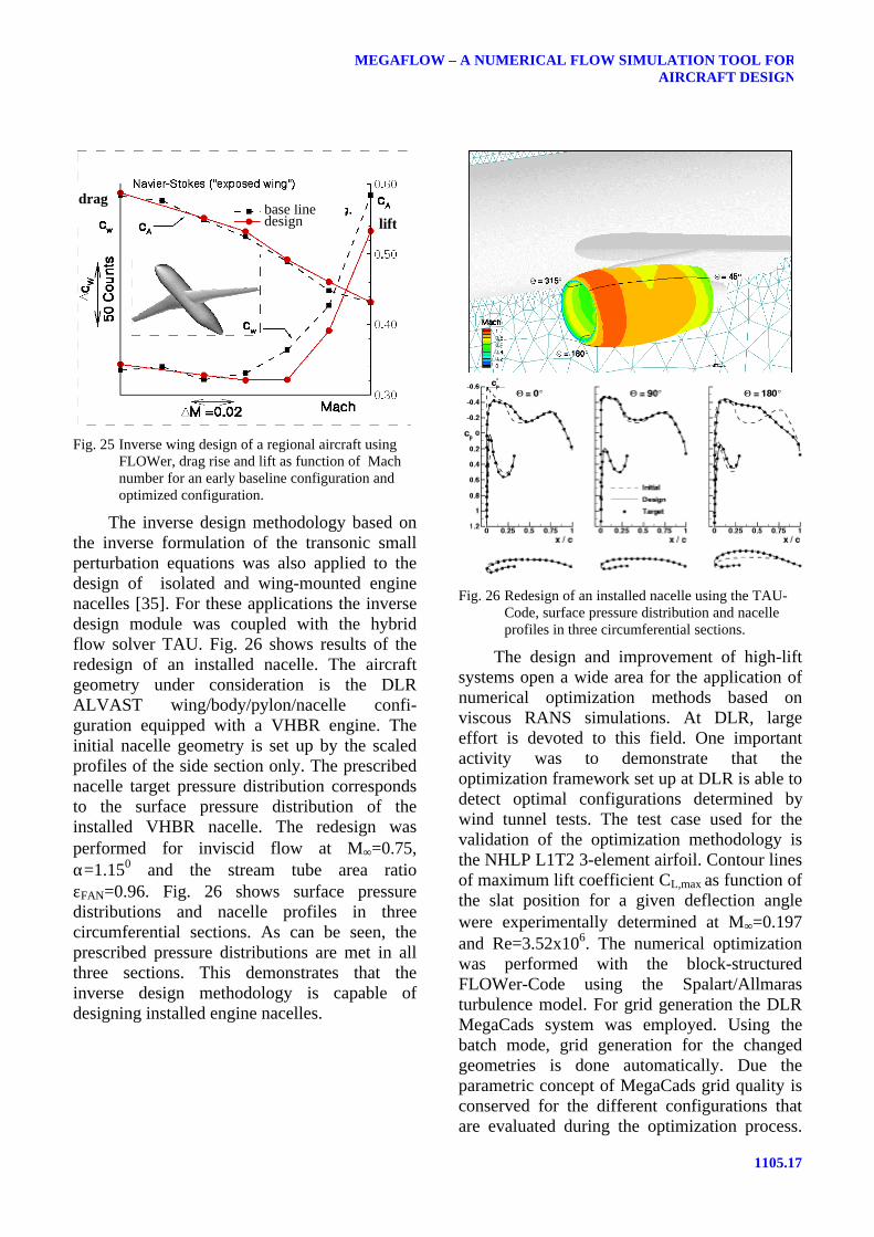
In Fig. 23 drag and lift coefficients for the rearend (RE) of the configuration as a function ofangle of attack are presented for different settingangles of the horizontal tail. The comparisonwith experimental data shows that theaerodynamic forces of tail planes can bepredicted with high accuracy.
inboard
outboard
AB
Section ASection A
Section B
Kroll, N., Rossow, C.C., Schwamborn, D., Becker, K., Heller, G.
1105.16
Fig. 23 Tail plane calculations with the hybrid Navier-Stokes solver TAU at M∞=0.85, Re=2.7x10⁶,lift (a)and drag coefficient (b) as function of angleof attack for different setting angles of horizontalplane.
For the regional jet aircraft Dornier DO728, the potential of wing tip extensions toincrease cruise performance was investigated[33]. The numerical tool employed was theFLOWer-Code, and computational meshes withC-H topology were used. Fig. 24 gives a viewof the wing/body configuration with wing tipextension. For different wing tip extensions thecorresponding surface pressure distributions aredisplayed. Note that for all configurations of theshark-family, no supersonic regions on the wingextension occurred. Fig. 24 also shows theimprovement in drag reduction in percentcompared to the standard wing withoutextensions. The performance predictions of thenumerical study for the different configurationscould clearly be confirmed by wind tunnelmeasurements.
5 Shape Design and Optimization
Aerodynamic shape optimization based onnumerical methods is a key issue for futureaircraft design. It offers the possibility ofdesigning or improving aircraft componentswith respect to a prespecified figure of meritsubject to geometrical and physical constraints.
cp0.20
0.100.00
-0.10-0.20-0.30
-0.40-0.50
-0.60-0.70-0.80
-0.90-1.00
-1.10-1.20-1.30
-1.40
standard winglet
cp0.200.100.00
-0.10-0.20-0.30-0.40
-0.50-0.60-0.70
-0.80-0.90-1.00-1.10
-1.20-1.30-1.40
shark
cp0.200.100.00
-0.10-0.20-0.30-0.40-0.50-0.60-0.70-0.80-0.90-1.00-1.10-1.20-1.30-1.40
sharkflat
cp0.20
0.100.00
-0.10-0.20-0.30
-0.40-0.50-0.60
-0.70-0.80
-0.90-1.00-1.10
-1.20-1.30
-1.40
supershark
Fig. 24 Design study of wing tip extensions for DO 728using the Navier-Stokes solver FLOWer, surfacepressure distributions for different shapes,improvement in drag reduction in percent.
In the context of the DO 728/928 aircraftdevelopment various wing designs for transonicflow were performed at DLR with the inversemode of the Navier-Stokes solver FLOWer. Asdesign target suitable surface pressuredistributions were specified subject togeometrical constraints and a given liftcoefficient. Fig. 25 shows the comparison ofdrag rise between an early baseline wing and animproved wing as a function of Mach number.The reduction of drag in the higher Machnumber range is clearly visible. The constraintwith respect to the lift coefficient was satisfied.
1105.17
MEGAFLOW – A NUMERICAL FLOW SIMULATION TOOL FORAIRCRAFT DESIGN
Fig. 25 Inverse wing design of a regional aircraft usingFLOWer, drag rise and lift as function of Machnumber for an early baseline configuration andoptimized configuration.
The inverse design methodology based onthe inverse formulation of the transonic smallperturbation equations was also applied to thedesign of isolated and wing-mounted enginenacelles [35]. For these applications the inversedesign module was coupled with the hybridflow solver TAU. Fig. 26 shows results of theredesign of an installed nacelle. The aircraftgeometry under consideration is the DLRALVAST wing/body/pylon/nacelle confi-guration equipped with a VHBR engine. Theinitial nacelle geometry is set up by the scaledprofiles of the side section only. The prescribednacelle target pressure distribution correspondsto the surface pressure distribution of theinstalled VHBR nacelle. The redesign wasperformed for inviscid flow at M∞=0.75,α=1.150 and the stream tube area ratioεFAN=0.96. Fig. 26 shows surface pressuredistributions and nacelle profiles in threecircumferential sections. As can be seen, theprescribed pressure distributions are met in allthree sections. This demonstrates that theinverse design methodology is capable ofdesigning installed engine nacelles.
Fig. 26 Redesign of an installed nacelle using the TAU-Code, surface pressure distribution and nacelleprofiles in three circumferential sections.
The design and improvement of high-liftsystems open a wide area for the application ofnumerical optimization methods based onviscous RANS simulations. At DLR, largeeffort is devoted to this field. One importantactivity was to demonstrate that theoptimization framework set up at DLR is able todetect optimal configurations determined bywind tunnel tests. The test case used for thevalidation of the optimization methodology isthe NHLP L1T2 3-element airfoil. Contour linesof maximum lift coefficient CL,max as function ofthe slat position for a given deflection anglewere experimentally determined at M∞=0.197and Re=3.52x10⁶. The numerical optimizationwas performed with the block-structuredFLOWer-Code using the Spalart/Allmarasturbulence model. For grid generation the DLRMegaCads system was employed. Using thebatch mode, grid generation for the changedgeometries is done automatically. Due theparametric concept of MegaCads grid quality isconserved for the different configurations thatare evaluated during the optimization process.
base linedesign lift
drag
Kroll, N., Rossow, C.C., Schwamborn, D., Becker, K., Heller, G.
1105.18
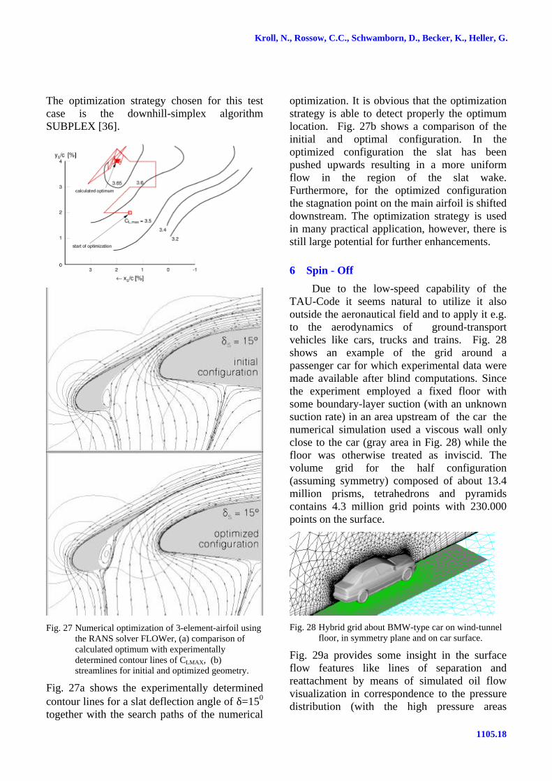
The optimization strategy chosen for this testcase is the downhill-simplex algorithmSUBPLEX [36].
Fig. 27 Numerical optimization of 3-element-airfoil usingthe RANS solver FLOWer, (a) comparison ofcalculated optimum with experimentallydetermined contour lines of CLMAX, (b)streamlines for initial and optimized geometry.
Fig. 27a shows the experimentally determinedcontour lines for a slat deflection angle of δ=150
together with the search paths of the numerical
optimization. It is obvious that the optimizationstrategy is able to detect properly the optimumlocation. Fig. 27b shows a comparison of theinitial and optimal configuration. In theoptimized configuration the slat has beenpushed upwards resulting in a more uniformflow in the region of the slat wake.Furthermore, for the optimized configurationthe stagnation point on the main airfoil is shifteddownstream. The optimization strategy is usedin many practical application, however, there isstill large potential for further enhancements.
6 Spin - Off
Due to the low-speed capability of theTAU-Code it seems natural to utilize it alsooutside the aeronautical field and to apply it e.g.to the aerodynamics of ground-transportvehicles like cars, trucks and trains. Fig. 28shows an example of the grid around apassenger car for which experimental data weremade available after blind computations. Sincethe experiment employed a fixed floor withsome boundary-layer suction (with an unknownsuction rate) in an area upstream of the car thenumerical simulation used a viscous wall onlyclose to the car (gray area in Fig. 28) while thefloor was otherwise treated as inviscid. Thevolume grid for the half configuration(assuming symmetry) composed of about 13.4million prisms, tetrahedrons and pyramidscontains 4.3 million grid points with 230.000points on the surface.
Fig. 28 Hybrid grid about BMW-type car on wind-tunnelfloor, in symmetry plane and on car surface.
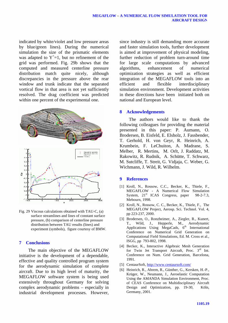
Fig. 29a provides some insight in the surfaceflow features like lines of separation andreattachment by means of simulated oil flowvisualization in correspondence to the pressuredistribution (with the high pressure areas
1105.19
MEGAFLOW – A NUMERICAL FLOW SIMULATION TOOL FORAIRCRAFT DESIGN
indicated by white/violet and low pressure areasby blue/green lines). During the numericalsimulation the size of the prismatic elementswas adapted to Y+=1, but no refinement of thegrid was performed. Fig. 29b shows that thecomputed and measured centerline pressuredistribution match quite nicely, althoughdiscrepancies in the pressure above the rearwindow and trunk indicate that the separatedvortical flow in that area is not yet sufficientlyresolved. The drag coefficient was predictedwithin one percent of the experimental one.
Fig. 29 Viscous calculations obtained with TAU-C, (a)surface streamlines and lines of constant surfacepressure, (b) comparison of centerline pressuredistribution between TAU results (lines) andexperiment (symbols), figure courtesy of BMW.
7 Conclusions
The main objective of the MEGAFLOWinitiative is the development of a dependable,effective and quality controlled program systemfor the aerodynamic simulation of completeaircraft. Due to its high level of maturity, theMEGAFLOW software system is being usedextensively throughout Germany for solvingcomplex aerodynamic problems – especially inindustrial development processes. However,
since industry is still demanding more accurateand faster simulation tools, further developmentis aimed at improvement of physical modeling,further reduction of problem turn-around timefor large scale computations by advancedalgorithms, enhancement of numericaloptimization strategies as well as efficientintegration of the MEGAFLOW tools into anefficient and flexible interdisciplinarysimulation environment. Development activitiesin these directions have been initiated both onnational and European level.
8 Acknowledgements
The authors would like to thank thefollowing colleagues for providing the materialpresented in this paper: P. Aumann, O.Brodersen, B. Eisfeld, E. Elsholz, J. Fassbender,T. Gerhold, H. von Geyr, R. Heinrich, A.Krumbein, F. LeChuiton, A. Madrane, S.Melber, R. Mertins, M. Orlt, J. Raddatz, M.Rakowitz, R. Rudnik, A. Schütte, T. Schwarz,M. Sutcliffe, T. Streit, G. Vidjaja, C. Weber, G.Wichmann, J. Wild, R. Wilhelm.
9 References
[1] Kroll, N., Rossow, C.C., Becker, K., Thiele, F.,MEGAFLOW - A Numerical Flow SimulationSystem, 21st ICAS Congress, paper 98-2-7.3,Mebourn, 1998.
[2] Kroll, N., Rossow, C. C., Becker, K., Thiele, F., TheMEGAFLOW Project, Aerosp. Sci. Technol. Vol. 4,pp 223-237, 2000.
[3] Brodersen, O., Ronzheimer, A., Ziegler, R., Kunert,T., Wild, J., Hepperle, M., AerodynamicApplications Using MegaCads, 6th InternationalConference on Numerical Grid Generation onComputational Field Simulations, Ed. M. Cross et al.,ISGG, pp 793-802, 1998.
[4] Becker, K., Interactive Algebraic Mesh Generationfor Twin Jet Transport Aircraft, Proc. 3rd Int.Conference on Num. Grid Generation, Barcelona,1991.
[5] CentaurSoft, http://www.centaursoft.com/[6] Heinrich, R., Ahrem, R., Günther, G., Kersken, H.-P.,
Krüger, W., Neumann, J., Aeroelastic ComputationUsing the AMANDA Simulation Environment, Proc.of CEAS Conference on Multidisciplinary AircraftDesign and Optimization, pp. 19-30, Köln,Germany, 2001.
Kroll, N., Rossow, C.C., Schwamborn, D., Becker, K., Heller, G.
1105.20
[7] http://www.mpcci.org/[8] Kroll, N., Radespiel, R., Rossow, C.-C., Accurate and
Efficient Flow Solvers for 3D-Applications onStructured Meshes, AGARD R-807, 4.1-4.59, 1995.
[9] Aumann, P., Barnewitz, H., Schwarten, H., Becker,K., Heinrich, R., Roll, B., Galle, M., Kroll, N.,Gerhold, Th., Schwamborn, D., Franke, M.,MEGAFLOW: Parallel Complete Aircraft CFD.Parallel Computing, Vol. 27, pp 415-440, 2001.
[10] Rung, T., Lübcke, H., Franke, M., Xue, L., Thiele, F.,Fu, S., Assessment of Explicit Algebraic StressModels in Transonic Flows, Proceedings of the 4th
Symposium on Engineering Turbulence Modelingand Measurements, France, pp. 659-668, 1999.
[11] Kok, J.C., Brandsma, F.J., Turbulence Model BasedVortical Flow Computations for a Sharp Edged DeltaWing in Transonic Flow Using the Full Navier-Stokes Equations, NLR-CR-2000-342, 2000.
[12] Wallin, S., Johansson, A.V., An Explicit AlgebraicReynolds Stress Model for Incompressible andCompressible Turbulent Flows, J. Fluid Mech., Vol.403, pp. 89-132, 2000.
[13] Rakowitz, M., Sutcliffe, M., Eisfeld, B.,Schwamborn, D., Bleecke, H., Faßbender, J.,Structured and Unstructured Computations on theDLR-F4 Wing-Body Configuration, AIAA 2002-0837, 2002.
[14] LeChuiton, F., Actuator Disc Modeling for RotoryWings, 28th European Rotorcraft Forum, Bristol,England, 2002.
[15] Krumbein, A., Coupling of the DLR Navier-StokesSolver FLOWer with an eN-Database Method forLaminar-Turbulent Transition Prediction on Airfoils,Notes on Numerical Fluid Mechanics, Vol. 77, pp.92-99, 2002.
[16] Heinrich, R., Kalitzin, N., Numerical Simulation ofThree-Dimensional Flows Using the ChimeraTechnique, Notes on Numerical Fluid Mechanics,Vol. 72, Vieweg Braunschweig, pp. 15-23, 1999.
[17] Schwarz, Th., Development of a Wall Treatment forNavier-Stokes Computations Using the Overset GridTechnique, 26th European Rotorcraft Forum, Paper45, 2000.
[18] Takanashi, S., Iterative Three-Dimensional TransonicWing Design Using Integral Equations, Journal ofAircraft, Vol 22, No 8., 1985.
[19] Bartelheimer, W., An Improved Integral EquationMethod for the Design of Transonic Airfoils andWings, AIAA 95-1688,1995.
[20] Jameson, A., Martinelli, L., and Pierce, N., OptimumAerodynamic Design Using the Navier-StokesEquations. Theoret. Comput. Fluid Dynamics, Vol10, pp. 213-237, 1998.
[21] Gauger, N., Brezillon, J., Aerodynamic ShapeOptimization Using Adjoint Method, Journal of theAeronautical Society of India, to appear in 2002.
[22] Gerhold T., Friedrich, O., Evans J., Galle, M.,Calculation of Complex Three-DimensionalConfigurations Employing the DLR-TAU Code,AIAA 97-0167, 1997.
[23] Schütte, A., Einarsson, G., Madrane, A., Schöning,B., Mönnich, W., Krüger, W.-R., NumericalSimulation of Maneuvering Aircraft by CFD andFlight Mechanic Coupling, RTO Symposium, Paris,April, 2002.
[24] http://www.aiaa.org/tc/apa/dragpredworkshop/dpw.html.
[25] Monsen, E., Franke, M., Rung, T., Aumann, P.,Ronzheimer, A., Assessment of Advanced Transport-Equation Turbulence Models for AircraftAerodynamic Performance Prediction, AIAA 99-3701, 1999.
[26] Rudnik, R., Melber, S., Ronzheimer, A., Brodersen,O., Three-Dimensional Navier-Stokes Simulationsfor Transport Aircraft High Lift Configurations,Journal of Aircraft, Vol. 38, pp. 895-903, 2001.
[27] Rudnik, R., Towards CFD Validation for 3D HighLift Flows – EUROLIFT, ECCOMAS 2001,Swansea, United Kingdom, 2001.
[28] Melber, S., Wild, J.; Rudnik, R., Overview about theNLRS-Project on Numerical High Lift Research,DLR-IB 124, 2002/15, 2002.
[29] Brodersen, O., Stürmer, A., Drag Prediction ofEngine-Airframe Interference Effects UsingUnstructured Nvier-Stokes Calculations, AIAA2001-2414, 2001.
[30] Rudnik, R., Rossow, C.C., v. Geyr, H., NumericalSimulation of Engine/Airframe Integration for High-Bypass Engines, Aerosp. Sci. and Technol., Vol. 6,pp 31-42, 2002.
[31] Mertins, R., Barakat, S., Elsholz, E., 3D ViscousFlow Simulation on Spoiler and Flap Configurations,CEAS Aerospace Aerodynamics ResearchConference, Paper No. 65, Cambridge, UnitedKingdom, 2002.
[32] Weber, C., 3D Navier-Stokes-Berechnungen an einerA380-Leitwerkskonfiguration, Airbus Report,EGAG-237/02, 2002.
[33] Heller, G., Dirmeier, S., Kreuzer, P., Streit, Th.,Aerodynamische Leistungssteigerung durch Flügel-spitzenmodifikationen am Beispiel der Envoy 7,DGLR Symposium Paper No. 2001-103, 2001.
[34] Streit, Th., Wichmann, G., Rohard, C.H.,Nachrechnung und Entwurf von transsonischenTragflügeln für die DO-728 / DO-928, DLR IB 129-99/13, 1999.
[35] Wilhelm, R., An Inverse Design Method forDesigning Isolated and Wing-Mounted EngineNacelles, AIAA 2002-0104.
[36] Wild, J., Validation of Numerical Optimization ofHigh-Lift Multi-Element Airfoils based on Navier-Stokes-Equations, AIAA 2002-2939, 2002.