Embed Size (px)
Citation preview

S69013_002
MEF 66
Draft (R2)
© MEF Forum 2019. Any reproduction of this document, or any portion thereof, shall contain the following statement: "Reproduced with permission of MEF Forum." No user of this document is authorized to modify any
of the information contained herein.
1
2
Draft Standard 3
MEF 66 Draft (R2) 4
5
6
SOAM for IP Services 7
Release 2 8
9
March 2019 10
11
This draft represents MEF work in progress and is 12
subject to change. 13
This draft document represents MEF work in progress, has not achieved full MEF standardiza-14
tion and is subject to change. There are known unresolved issues that are likely to result in 15
changes before this becomes a fully endorsed MEF Standard. The reader is strongly encouraged 16
to review the Release Notes when making a decision on adoption. Additionally, because this 17
document has not been adopted as a Final Specification in accordance with MEF's Bylaws, 18
Members are not obligated to license patent claims that are essential to implementation of this 19
document under MEF's Bylaws. 20

S69013_002
MEF 66
Draft (R2)
© MEF Forum 2019. Any reproduction of this document, or any portion thereof, shall contain the following statement: "Reproduced with permission of MEF Forum." No user of this document is authorized to modify any
of the information contained herein.
Disclaimer 21
The information in this publication is freely available for reproduction and use by any recipient 22
and is believed to be accurate as of its publication date. Such information is subject to change 23
without notice and MEF Forum (MEF) is not responsible for any errors. MEF does not assume 24
responsibility to update or correct any information in this publication. No representation or war-25
ranty, expressed or implied, is made by MEF concerning the completeness, accuracy, or applica-26
bility of any information contained herein and no liability of any kind shall be assumed by MEF 27
as a result of reliance upon such information. 28
The information contained herein is intended to be used without modification by the recipient or 29
user of this document. MEF is not responsible or liable for any modifications to this document 30
made by any other party. 31
The receipt or any use of this document or its contents does not in any way create, by implication 32
or otherwise: 33
a) any express or implied license or right to or under any patent, copyright, trademark or 34
trade secret rights held or claimed by any MEF member which are or may be associat-35
ed with the ideas, techniques, concepts or expressions contained herein; nor 36
b) any warranty or representation that any MEF members will announce any product(s) 37
and/or service(s) related thereto, or if such announcements are made, that such an-38
nounced product(s) and/or service(s) embody any or all of the ideas, technologies, or 39
concepts contained herein; nor 40
c) any form of relationship between any MEF member and the recipient or user of this 41
document. 42
Implementation or use of specific MEF standards or recommendations and MEF specifications 43
will be voluntary, and no Member shall be obliged to implement them by virtue of participation 44
in MEF Forum. MEF is a non-profit international organization to enable the development and 45
worldwide adoption of agile, assured and orchestrated network services. MEF does not, express-46
ly or otherwise, endorse or promote any specific products or services. 47
© MEF Forum 2019. All Rights Reserved. 48
49

S69013_002 SOAM for IP Services
MEF 66
Draft (R2)
© MEF Forum 2019. Any reproduction of this document, or any portion thereof, shall contain the following statement: "Reproduced with permission of MEF Forum." No user of this document is authorized to modify any
of the information contained herein.
Page iii
Table of Contents 50
1 List of Contributing Members ........................................................................................... 1 51
2 Abstract ................................................................................................................................ 1 52
3 Release Notes ....................................................................................................................... 1 53
4 Terminology and Abbreviations ........................................................................................ 2 54
5 Compliance Levels .............................................................................................................. 5 55
6 Numerical Prefix Conventions ........................................................................................... 5 56
7 Introduction ......................................................................................................................... 6 57
7.1 Document Structure ........................................................................................................... 7 58
7.2 Use Cases ........................................................................................................................... 7 59
8 Fault Management .............................................................................................................. 9 60
8.1 FM Use Cases .................................................................................................................... 9 61
8.1.1 End-to-End Monitoring ........................................................................................................... 9 62
8.1.2 UNI Access Link ................................................................................................................... 11 63
8.1.3 IPVC Monitoring .................................................................................................................. 13 64
8.2 FM Tool Requirements .................................................................................................... 14 65
8.2.1 Proactive Monitoring ............................................................................................................ 14 66
8.2.1.1 BFD Overview ................................................................................................................... 14 67
8.2.1.2 BFD Support ...................................................................................................................... 15 68
8.2.2 On-Demand Fault Monitoring ............................................................................................... 16 69
8.3 FM Reporting .................................................................................................................. 18 70
9 Performance Management ............................................................................................... 20 71
9.1 PM Use Cases .................................................................................................................. 20 72
9.1.1 Location to Location Monitoring .......................................................................................... 25 73
9.1.2 IPVC Monitoring .................................................................................................................. 27 74
9.2 PM Common Requirements ............................................................................................ 30 75
9.2.1 Life Cycle .............................................................................................................................. 30 76
9.2.1.1 General Overview of Parameters ...................................................................................... 30 77
9.2.1.2 Proactive and On-Demand PM Sessions ........................................................................... 31 78
9.2.1.3 Create ................................................................................................................................ 31 79
9.2.1.4 Delete ................................................................................................................................. 32 80
9.2.1.5 Start and Stop .................................................................................................................... 32 81
9.2.1.6 Measurement Intervals ...................................................................................................... 33 82
9.2.1.7 Repetition Time .................................................................................................................. 34 83
9.2.1.8 Alignment of Measurement Intervals ................................................................................. 34 84
9.2.1.9 Summary of Time Parameters ........................................................................................... 35 85
9.2.2 Storage................................................................................................................................... 35 86
9.2.2.1 Measurement Interval Data Sets ....................................................................................... 37 87
9.2.2.2 Measurement Bins ............................................................................................................. 38 88
9.2.2.3 Volatility ............................................................................................................................ 40 89
9.2.2.4 Measurement Interval Status ............................................................................................. 41 90
9.3 PM Implementation Requirements .................................................................................. 41 91
9.3.1 PM Implementation Description ........................................................................................... 43 92
9.4 PM Tool Requirements .................................................................................................... 54 93

S69013_002 SOAM for IP Services
MEF 66
Draft (R2)
© MEF Forum 2019. Any reproduction of this document, or any portion thereof, shall contain the following statement: "Reproduced with permission of MEF Forum." No user of this document is authorized to modify any
of the information contained herein.
Page iv
9.4.1 Active Measurement ............................................................................................................. 54 94
9.4.1.1 TWAMP Light .................................................................................................................... 54 95
9.4.1.2 STAMP ............................................................................................................................... 55 96
9.4.1.2.1 Session-Sender Behavior ............................................................................................................................ 55 97
9.4.1.2.2 Session-Reflector Behavior ........................................................................................................................ 55 98
9.4.1.2.3 Interoperability with TWAMP Light .......................................................................................................... 56 99
9.4.1.3 TWAMP ............................................................................................................................. 56 100
9.4.1.3.1 Session-Sender Behavior ............................................................................................................................ 56 101
9.4.1.3.2 Session-Reflector Behavior ........................................................................................................................ 57 102
9.5 Threshold Crossing Alerts (TCAs) .................................................................................. 57 103
9.5.1 TCA Reporting ...................................................................................................................... 58 104
9.5.1.1 Stateless TCA Reporting .................................................................................................... 58 105
9.5.1.2 Stateful TCA Reporting ...................................................................................................... 59 106
9.5.2 SOAM PM Thresholds for TCAs .......................................................................................... 60 107
9.5.3 SOAM PM TCA Notification Messages ............................................................................... 67 108
10 Hybrid Measurement........................................................................................................ 69 109
10.1 Alternate Marking Explanation ....................................................................................... 69 110
10.1.1 Single-Marking Methodology ............................................................................................... 71 111
10.1.2 Mean Delay ........................................................................................................................... 71 112
10.1.3 Double-Marking Methodology ............................................................................................. 72 113
10.2 Alternate Marking for FM ............................................................................................... 72 114
10.3 Alternate Marking for PM ............................................................................................... 72 115
11 References .......................................................................................................................... 74 116
Appendix A Life Cycle Terminology (Informative) .............................................................. 77 117
A.1 Proactive PM Sessions..................................................................................................... 77 118
A.2 On-Demand PM Sessions ................................................................................................ 78 119
A.3 PM Sessions With Clock-Aligned Measurement Intervals and Repetition Time of 120
“None” ....................................................................................................................................... 79 121
A.4 PM Sessions With Clock-Aligned Measurement Intervals and Repetition Times Not 122
Equal To “None” ....................................................................................................................... 80 123
Appendix B Measurement Bins (Informative) ...................................................................... 84 124
B.1 Description of Measurement Bins ................................................................................... 84 125
B.2 One-way Packet Delay Performance ............................................................................... 85 126
B.3 One-way Inter Packet Delay Performance ...................................................................... 85 127
B.4 One-way Packet Delay Range Performance .................................................................... 85 128
B.4.1 Case 1: Q1(x) ......................................................................................................................... 85 129
B.4.2 Case 2: Qh(x) ......................................................................................................................... 86 130
Appendix C Statistical Considerations for Loss Measurement (Informative) ................... 87 131
C.1 Synthetic Packets and Statistical Methods ...................................................................... 87 132
Appendix D Normalizing Measurements for PDR (Informative) ....................................... 94 133
D.1 Topology Shifts ............................................................................................................... 95 134
D.1.1 Minimum Delay Becomes Significantly Smaller .................................................................. 95 135
D.1.2 Minimum Delay Becomes Significantly Larger ................................................................... 95 136
D.2 Impact of Lack of ToD Synchronization ......................................................................... 96 137

S69013_002 SOAM for IP Services
MEF 66
Draft (R2)
© MEF Forum 2019. Any reproduction of this document, or any portion thereof, shall contain the following statement: "Reproduced with permission of MEF Forum." No user of this document is authorized to modify any
of the information contained herein.
Page v
Appendix E Calculation of SLS Performance Metrics (Informative) ................................. 98 138
E.1 One-way Packet Delay .................................................................................................... 98 139
E.2 One-way Mean Packet Delay .......................................................................................... 99 140
E.3 One-way Packet Loss ...................................................................................................... 99 141
142

S69013_002 SOAM for IP Services
MEF 66
Draft (R2)
© MEF Forum 2019. Any reproduction of this document, or any portion thereof, shall contain the following statement: "Reproduced with permission of MEF Forum." No user of this document is authorized to modify any
of the information contained herein.
Page vi
List of Figures 143
Figure 1 – Example of an IPVC connecting three UNIs ................................................................ 8 144
Figure 2 – End-to-End BFD .......................................................................................................... 10 145
Figure 3 – UNI Access Link BFD with Subscriber Provided CE................................................. 11 146
Figure 4 – UNI Access Link BFD with SP Managed CE ............................................................. 12 147
Figure 5 – PE-PE BFD Session .................................................................................................... 13 148
Figure 6 – SLS-RPs, MPs and Pair of MPs .................................................................................. 21 149
Figure 7 – SLS Method 1 and Method 2 Comparison .................................................................. 23 150
Figure 8 - Example MP Locations ................................................................................................ 24 151
Figure 9 – Active PM Location to Location via IP-PMVC .......................................................... 26 152
Figure 10 – IPVC EP to IPVC EP Active Measurement .............................................................. 28 153
Figure 11 – Active Measurement when MPs are not at – IPVC EPs ........................................... 29 154
Figure 12 – Example of Measurement Bins and Intervals ............................................................ 36 155
Figure 13 – Example of Packet Count Measurements .................................................................. 37 156
Figure 14 – Single-Ended Function .............................................................................................. 42 157
Figure 15 - Timestamp Locations ................................................................................................. 47 158
Figure 16 – Stateless TCA Reporting Example ............................................................................ 59 159
Figure 17 – Stateful TCA Reporting Example ............................................................................. 60 160
Figure 18 – Upper Bin Count for Threshold Crossing ................................................................. 61 161
Figure 19 – AltM description ........................................................................................................ 70 162
Figure 20 – AltM measurement strategies .................................................................................... 71 163
Figure 21 – Measurement Interval Terminology .......................................................................... 78 164
Figure 22 – Illustration of non-Repetitive, On-Demand PM Session ........................................... 79 165
Figure 23 – Example of Repetitive On-Demand PM Session ...................................................... 79 166
Figure 24 – Example Proactive PM Session with Clock-Aligned Measurement Interval ............ 80 167
Figure 25 – Example On-Demand PM Session with Clock-Aligned Measurement Interval ....... 81 168
Figure 26 – Second Example of On-Demand PM Session with Clock-Aligned Measurement 169
Interval .................................................................................................................................. 82 170
Figure 27 – Hypothesis Test for Synthetic Packet Loss Measurements ....................................... 87 171
Figure 28 – Density Curve and Probability of Exceeding the Objective ...................................... 88 172
Figure 29 – Synthetic Loss Performance Example 1 .................................................................... 89 173
Figure 30 – Synthetic Loss Performance Example 2 .................................................................... 90 174
Figure 31 – Synthetic Loss Performance Example 3 .................................................................... 90 175
Figure 32 – Synthetic Loss Performance Example 4 .................................................................... 91 176
Figure 33 – Example PDR Distribution (normalized), and Bins .................................................. 94 177
Figure 34 – Reduction in Minimum Delay, due to Network Topology Change .......................... 95 178
Figure 35 – Increase in Minimum Delay, due to Network Topology Change ............................. 96 179
Figure 36 – Lack of ToD Synchronization ................................................................................... 96 180
181

S69013_002 SOAM for IP Services
MEF 66
Draft (R2)
© MEF Forum 2019. Any reproduction of this document, or any portion thereof, shall contain the following statement: "Reproduced with permission of MEF Forum." No user of this document is authorized to modify any
of the information contained herein.
Page vii
List of Tables 182
Table 1 – Terminology and Abbreviations ..................................................................................... 4 183
Table 2 – Numerical Prefix Conventions ........................................................................................ 5 184
Table 3 - On-demand Tool Recommended Defaults .................................................................... 18 185
Table 4 – Time Parameters ........................................................................................................... 35 186
Table 5 – Example Measurement Bin Configuration ................................................................... 40 187
Table 6 – Mandatory Stateful Single-Ended Data Set .................................................................. 51 188
Table 7 – Mandatory Stateless Single-Ended Data Set ................................................................ 53 189
Table 8 – Mandatory Single-Ended Data Set with Clock Synchronization .................................. 54 190
Table 9 – SOAM Performance Metrics TCA ............................................................................... 63 191
Table 10 – TCA Notification Message Fields .............................................................................. 68 192
Table 11 – Comparison of TCA Fields in X.73x and MEF 61 ..................................................... 68 193
Table 12 – CoV Calculations with Message Period 1s ................................................................. 93 194
Table 13 – CoV Calculations with Message Period 100ms .......................................................... 93 195
196

S69013_002 SOAM for IP Services
MEF 66
Draft (R2)
© MEF Forum 2019. Any reproduction of this document, or any portion thereof, shall contain the following
statement: "Reproduced with permission of MEF Forum." No user of this document is authorized to modify any
of the information contained herein.
Page 1
1 List of Contributing Members 197
The following members of the MEF participated in the development of this document and have 198
requested to be included in this list. 199
Editor Note 1: This list will be finalized before Letter Ballot. Any member that comments in at 200
least one CfC is eligible to be included by opting in before the Letter Ballot is 201
initiated. Note it is the MEF member that is listed here (typically a company or 202
organization), not their individual representatives. 203
ABC Networks 204
XYZ Communications 205
ACME Corporation 206
2 Abstract 207
This document specifies Service Operations, Administration, and Maintenance (SOAM) of IP 208
Services described using the IP Service Attributes as defined in MEF 61.1 [33]. This covers both 209
Fault Management (FM) and Performance Management (PM) of IP services. 210
The scope of this document is to define how Service Operations, Administration, and Mainte-211
nance (SOAM) Fault Management (FM) and Performance Monitoring (PM) can be applied to IP 212
Services described using Service Attributes defined in MEF 61.1 [33]. The goal of this docu-213
ment is to define a set of specific fault and performance measurement methods that are recom-214
mended to be implemented by equipment providers and Service Providers. The methods defined 215
include Proactive and On-demand Fault Management and active Performance Monitoring. 216
The focus of FM is on Bidirectional Forwarding Detection (BFD) as defined in RFC 5880 [11], 217
RFC 5881 [12], and RFC 5883 [13] for Proactive monitoring. Ping and traceroute using ICMP as 218
defined in RFC 792 [2] and RFC 4443 [8] are used for On-demand monitoring and defect locali-219
zation. These tools are well defined and broadly implemented today. This document defines 220
options, modes, and parameters for these tools based on defined use cases. The focus of PM for 221
Active Measurement is on Two-Way Active Measurement Protocol (TWAMP) and TWAMP 222
Light as defined in RFC 5357 [10] and Simple Two-way Active Measurement Protocol 223
(STAMP) as defined in draft-ietf-ippm-stamp [20]. TWAMP, TWAMP Light, and STAMP are 224
included in the scope to cover both complex and more simplified implementations. 225
3 Release Notes 226
There are no release notes for this Draft Standard. 227
228

S69013_002 SOAM for IP Services
MEF 66
Draft (R2)
© MEF Forum 2019. Any reproduction of this document, or any portion thereof, shall contain the following
statement: "Reproduced with permission of MEF Forum." No user of this document is authorized to modify any
of the information contained herein.
Page 2
4 Terminology and Abbreviations 229
This section defines the terms used in this document. In many cases, the normative definitions to 230
terms are found in other documents. In these cases, the third column is used to provide the refer-231
ence that is controlling, in other MEF or external documents. 232
In addition, terms defined in MEF 61.1 [33] are included in this document by reference, and are 233
not repeated in the table below. 234
235
Term Definition Reference
BFD Bidirectional Forwarding Detection IETF RFC
5880 [11]
Bidirectional Forward-
ing Detection
A protocol intended to detect faults in the bidirec-
tional path between two forwarding engines, includ-
ing interfaces, data link(s), and to the extent possible
the forwarding engines themselves, with potentially
very low latency.
IETF RFC
5880 [11]
ICM Infrastructure Control and Management MEF 55.1
ICMP Internet Control Message Protocol IETF RFC 792
[1] IETF RFC
4443 [8]
ICMP Ping A common term for a tool that uses an ICMP Echo
or Echo Reply Message as defined in RFC 792 [2]
for IPv4 and RFC 4443 [8] for IPv6.
This document
Infrastructure Control
and Management
The set of functionality providing domain specific
network and topology view resource management
capabilities including configuration, control and su-
pervision of the network infrastructure. ICM is re-
sponsible for providing coordinated management
across the network resources within a specific man-
agement and control domain. For example, a system
supporting ICM capabilities provides connection
management across a specific subnetwork domain.
Such capabilities may be provided within systems
such as subnetwork managers, SDN controllers, etc.
MEF 55 [32]
LSP Label Switched Path IETF RFC
3031 [5]
MD5 Message Digest Algorithm IETF RFC
1321 [3]
Measurement Interval A period of time during which measurements are
taken. Measurements initiated during one Measure-
ment Interval are kept separate from measurements
taken during other Measurement Intervals.
MEF 35.1 [31]

S69013_002 SOAM for IP Services
MEF 66
Draft (R2)
© MEF Forum 2019. Any reproduction of this document, or any portion thereof, shall contain the following
statement: "Reproduced with permission of MEF Forum." No user of this document is authorized to modify any
of the information contained herein.
Page 3
Term Definition Reference
Measurement Point An actively managed SOAM entity associated
with a specific service instance that can generate
and receive SOAM PDUs and track any responses.
This document
MI Measurement Interval MEF 35.1 [31]
MP Measurement Point This document
MPLS Multi-Protocol Label Switching IETF RFC
3031 [5]
On-demand SOAM actions that are initiated via manual inter-
vention for a limited time to carry out diagnostics.
MEF 35.1 [31]
Proactive monitoring SOAM actions that are carried on continuously to
permit timely reporting of fault and/or performance
status.
MEF 35.1 [31]
Service Operation Ad-
ministration and
Maintenance
Service OAM addresses Fault Management and Per-
formance Monitoring of services and devices used to
implement services.
This document
Service Orchestration
Functionality
The set of service management layer functionality
supporting an agile framework to streamline and
automate the service lifecycle in a sustainable fash-
ion for coordinated management supporting design,
fulfillment, control, testing, problem management,
quality management, usage measurements, security
management, analytics, and policy-based manage-
ment capabilities providing coordinated end-to-end
management and control of Layer 2 and Layer 3
Connectivity Services.
MEF 55 [32]
SHA1 Secure Hash Algorithm IETF RFC
3174 [6]
SM State Machine This document
SOAM Service Operation Administration and Maintenance This document
SOF Service Orchestration Functionality MEF 55 [32]
STAMP Simple Two-way Active Measurement Protocol IETF Draft
draft-ietf-ippm-
stamp [20]
TCA Threshold Crossing Alert GR-253 [34]
ToD Time of Day MEF 35.1 [31]
ICMP Traceroute A common term that refers to the ability to use the
Echo and Time Exceeded messages defined in RFC
792 [2] for IPv4 and RFC 4443 [8] for IPv6 to de-
termine the routing path from the source address to
the destination address.
This document

S69013_002 SOAM for IP Services
MEF 66
Draft (R2)
© MEF Forum 2019. Any reproduction of this document, or any portion thereof, shall contain the following
statement: "Reproduced with permission of MEF Forum." No user of this document is authorized to modify any
of the information contained herein.
Page 4
Term Definition Reference
TWAMP Two-way Active Measurement Protocol IETF RFC
5357 [10]
TWAMP Light TWAMP Light is significantly simplified mode of
TWAMP-Test part of TWAMP.
IETF RFC
5357, Appendix
I [10]
UBC Upper Bin Count MEF 35.1 [31]
UTC Coordinated Universal Time ISO 8601 [23]
Table 1 – Terminology and Abbreviations 236
237

S69013_002 SOAM for IP Services
MEF 66
Draft (R2)
© MEF Forum 2019. Any reproduction of this document, or any portion thereof, shall contain the following
statement: "Reproduced with permission of MEF Forum." No user of this document is authorized to modify any
of the information contained herein.
Page 5
5 Compliance Levels 238
The key words "MUST", "MUST NOT", "REQUIRED", "SHALL", "SHALL NOT", 239
"SHOULD", "SHOULD NOT", "RECOMMENDED", "NOT RECOMMENDED", "MAY", 240
and "OPTIONAL" in this document are to be interpreted as described in BCP 14 (RFC 2119 241
[4], RFC 8174 [16]) when, and only when, they appear in all capitals, as shown here. All key 242
words must be in bold text. 243
Items that are REQUIRED (contain the words MUST or MUST NOT) are labeled as [Rx] for 244
required. Items that are RECOMMENDED (contain the words SHOULD or SHOULD NOT) 245
are labeled as [Dx] for desirable. Items that are OPTIONAL (contain the words MAY or OP-246
TIONAL) are labeled as [Ox] for optional. 247
A paragraph preceded by [CRa]< specifies a conditional mandatory requirement that MUST be 248
followed if the condition(s) following the “<” have been met. For example, “[CR1]<[D38]” in-249
dicates that Conditional Mandatory Requirement 1 must be followed if Desirable Requirement 250
38 has been met. A paragraph preceded by [CDb]< specifies a Conditional Desirable Require-251
ment that SHOULD be followed if the condition(s) following the “<” have been met. A para-252
graph preceded by [COc]< specifies a Conditional Optional Requirement that MAY be followed 253
if the condition(s) following the “<” have been met. 254
6 Numerical Prefix Conventions 255
This document uses the prefix notation to indicate multiplier values as shown in Table 2. 256
257
Decimal Binary
Symbol Value Symbol Value
k 103
Ki 210
M 106 Mi 2
20
G 109 Gi 2
30
T 1012
Ti 240
P 1015
Pi 250
E 1018
Ei 260
Z 1021
Zi 270
Y 1024
Yi 280
Table 2 – Numerical Prefix Conventions 258

S69013_002 SOAM for IP Services
MEF 66
Draft (R2)
© MEF Forum 2019. Any reproduction of this document, or any portion thereof, shall contain the following
statement: "Reproduced with permission of MEF Forum." No user of this document is authorized to modify any
of the information contained herein.
Page 6
7 Introduction 259
SOAM provides the protocols, mechanisms, and procedures for monitoring faults and the per-260
formance of an IP Virtual Connection (IPVC). The use of SOAM in IP Services is not standard-261
ized although IP Services are widespread. This document describes the tools that are needed, 262
allowing equipment providers to understand what features and functions to include in their 263
equipment, and provides recommendations to IP Service Providers (SP) on how to use these 264
tools. 265
The document is divided into several sections covering Fault Management, Performance Man-266
agement, and Hybrid Measurement. The Fault Management section includes Use Cases, FM 267
Tool requirements, and FM reporting. The Performance Management section includes Use Cas-268
es, PM requirements, PM Tool requirements, and PM reporting. The Hybrid Measurement sec-269
tion includes informative discussion of Alternate Marking used for Hybrid Measurement. These 270
sections reference previous MEF work, other Standards Bodies work, or might expand upon that 271
work to support IP services. 272
For FM, Proactive monitoring and On-demand monitoring are specified. Proactive monitoring is 273
defined as SOAM actions that are carried on continuously to permit timely reporting of fault 274
and/or performance status. Within this document, Bidirectional Forwarding Detection (BFD) is 275
specified as the tool to be used for Proactive fault monitoring. Recommendations for BFD op-276
tions are included. On-demand fault monitoring is used to isolate a fault when one has been de-277
tected by Proactive monitoring or as a replacement for Proactive monitoring. 278
On-demand monitoring is defined as SOAM actions that are initiated via manual intervention for 279
a limited time to carry out diagnostics. Ping and traceroute are the tools used for On-demand 280
fault monitoring. Transmission and reception of ping and traceroute can use ICMP. Recom-281
mendations for options for these are included in this document. 282
For PM, Active Measurement using TWAMP Light/STAMP/TWAMP is specified. An Active 283
Measurement method depends on a dedicated measurement packet stream and observations of 284
the packets in that stream. These packets are used to measure packet delay, and packet loss. 285
MEF 61.1 [33] specifies one-way performance metrics which require Time of Day (ToD) clock 286
synchronization for PD measurements. Since ToD clock synchronization is often difficult to im-287
plement, two-way measurements, divided in half and identified as derived measurements can be 288
acceptable. Options for TWAMP, TWAMP Light, and STAMP are specified within the docu-289
ment. One Way Active Measurement Protocol (OWAMP) as defined in RFC 4656 [9] is not in-290
cluded in the scope of this document and is not recommended for use to perform PM due to the 291
requirement to implement the control protocol at each end of the service. 292
Passive Measurement depends solely on observation of one or more existing packet streams. The 293
streams are only used for measurement when they are observed for that purpose, but are present 294
whether or not measurements take place. Passive Measurement is not within the scope of this 295
document. 296
A Hybrid Measurement method is a combination of Active and Passive Measurement which 297
makes observations on a dedicated measurement stream using header or marked bits included 298

S69013_002 SOAM for IP Services
MEF 66
Draft (R2)
© MEF Forum 2019. Any reproduction of this document, or any portion thereof, shall contain the following
statement: "Reproduced with permission of MEF Forum." No user of this document is authorized to modify any
of the information contained herein.
Page 7
with an existing stream. The requirements for Hybrid Measurements are not discussed in this 299
document. However, Section 10 describes one example of the Hybrid method, Alternate Mark-300
ing. Hybrid Measurement methods such as Alternate Marking (AltM) are in the process of being 301
defined. As other SDOs complete work on these methods, this document can be updated to in-302
clude them. 303
7.1 Document Structure 304
This document is structured by measurement type. The Fault Management section contains use 305
cases, tool requirements, implementation recommendations, and reporting requirements. The 306
Performance Management section contains use cases, PM Solution requirements, Common PM 307
Requirements, Storage Requirements, Threshold Crossing Alert Requirements, PM Tool re-308
quirements, implementation recommendations, and reporting requirements. The Hybrid Moni-309
toring section provides an overview of AltM. Various appendices are provided to further assist 310
with tool and implementation decisions. 311
7.2 Use Cases 312
The use cases shown in this document provide examples of how FM (section 8.1), PM (section 313
9.1), and AltM (section 10) can be used in a SPs network. These use cases are not all encom-314
passing. Understanding how and why the SOAM tools are used will assist in understanding the 315
requirements and recommendations that are provided in this document. 316

S69013_002 SOAM for IP Services
MEF 66
Draft (R2)
© MEF Forum 2019. Any reproduction of this document, or any portion thereof, shall contain the following
statement: "Reproduced with permission of MEF Forum." No user of this document is authorized to modify any
of the information contained herein.
Page 8
317
Figure 1 – Example of an IPVC connecting three UNIs 318
Figure 1 shows a basic IPVC. For the purposes of this document, this basic IPVC will be dis-319
cussed in the use cases within this document. The single IPVC represented in Figure 1 connects 320
three Subscriber locations. The SP desires to monitor faults and performance of this IPVC. The 321
use cases within this document are used as examples and are provided as information only. 322
323

S69013_002 SOAM for IP Services
MEF 66
Draft (R2)
© MEF Forum 2019. Any reproduction of this document, or any portion thereof, shall contain the following
statement: "Reproduced with permission of MEF Forum." No user of this document is authorized to modify any
of the information contained herein.
Page 9
8 Fault Management 324
Fault Management (FM) provides the ability to detect failures within IP Services. This section 325
contains the Use Cases, Tool Requirements, and Implementation Recommendations for FM for 326
IP Services. 327
8.1 FM Use Cases 328
Faults that impact IP services include loss of connectivity due to network events, routing issues, 329
equipment failures or other events. A fault is characterized as failure to pass packets as opposed 330
to a performance degradation where packets can still pass but with excessive loss or delay. As 331
mentioned previously in this document, BFD is the recommended tool for Proactive FM. BFD is 332
a mature protocol that is widely implemented in CEs and PEs. For more information on BFD see 333
section 8.2.1. 334
BFD is often used to detect faults on a single hop within a network. The use of BFD across a 335
single physical link is out of scope except where used to detect faults on a UNI Access Link that 336
is a single hop. 337
To support On-demand FM, tools such as ICMP Ping and ICMP Traceroute are used. These 338
tools allow localization and isolation of a fault to be performed as needed. For more information 339
on these tools see section8.2.2. 340
There are several ways that FM can be used to support IP services. Examples of these are shown 341
in the following sections. 342
8.1.1 End-to-End Monitoring 343
An example of monitoring from IPVC End Point to IPVC End Point is shown in Figure 2. In 344
this case, the SP demarcation equipment (CE) at the customer premises supports BFD, which is 345
configured to run between each of the BFD Implementation (BFD IMP) at some regular interval. 346

S69013_002 SOAM for IP Services
MEF 66
Draft (R2)
© MEF Forum 2019. Any reproduction of this document, or any portion thereof, shall contain the following
statement: "Reproduced with permission of MEF Forum." No user of this document is authorized to modify any
of the information contained herein.
Page 10
347
Figure 2 – End-to-End BFD 348
Figure 2 shows an Asynchronous BFD session between each of the IPVC End Points. Any fail-349
ures of connectivity across the IPVC are detected. Examples of failures include loss of connec-350
tivity that occur between two IPVC EPs, high packet loss between two IPVC EPs that results in 351
loss of contiguous BFD packets, or a fault in the CE that causes the BFD implementation to fail 352
at an IPVC EP. Once the CEs are notified that a fault has occurred, they can take corrective ac-353
tion to reroute the packets to an alternate path. Depending on the transmission interval of BFD 354
packets, fault detection can occur faster than routing protocol fault detection. The SP is able to 355
configure a BFD session between the pair of CEs because the CEs are Provider-Managed. In the 356
case of Subscriber-Managed CE, the SP is not able to configure a BFD session between the pair 357
of CEs. 358

S69013_002 SOAM for IP Services
MEF 66
Draft (R2)
© MEF Forum 2019. Any reproduction of this document, or any portion thereof, shall contain the following
statement: "Reproduced with permission of MEF Forum." No user of this document is authorized to modify any
of the information contained herein.
Page 11
8.1.2 UNI Access Link 359
BFD can be configured to run between the Subscriber’s CE and the SP’s PE or between a SP 360
managed CE and other Subscriber equipment across the UNI Access Link. MEF 61.1 [33] de-361
fines the UNI Access Link BFD Service Attribute which is used to define the BFD session at-362
tributes. In this case, BFD is being used to detect faults that occur on the UNI Access Link ver-363
sus the CE to CE connectivity as discussed in section 8.1.1. 364
365
366
Figure 3 – UNI Access Link BFD with Subscriber Provided CE 367
Figure 3 shows several different UNI Access Link configurations when the CE is Subscriber-368
Managed. BFD sessions between the CE and the PE are configured and are used to detect faults 369
on the UNI Access Link. 370

S69013_002 SOAM for IP Services
MEF 66
Draft (R2)
© MEF Forum 2019. Any reproduction of this document, or any portion thereof, shall contain the following
statement: "Reproduced with permission of MEF Forum." No user of this document is authorized to modify any
of the information contained herein.
Page 12
371
Figure 4 – UNI Access Link BFD with SP Managed CE 372
Figure 4 shows similar UNI Access Link configurations but in these configurations the CE is 373
Provider-Managed. The BFD session is configured between the managed CE and some Sub-374
scriber equipment on the other side of the UNI Access Link. 375
Using BFD to monitor the UNI Access Link can be required if the physical connection between 376
the CE and PE does not provide fault notification. The connection appears as a single hop and 377
BFD is implemented as described in IETF RFC 5881 [12]. 378
A BFD session that is active on the UNI Access Link can be used to detect faults that cause a 379
rerouting of the Subscriber’s traffic to another UNI Access Link. Such re-routing can occur only 380
when there is an additional UNI Access Link that is not impacted by the fault. 381
Faults detected by the BFD session(s) in these Use Cases can include UNI interface failures, UNI 382
physical connectivity failure, or CE, PE, or Subscriber Equipment failure. 383
384
S69013_002 SOAM for IP Services
MEF 66
Draft (R2)
© MEF Forum 2019. Any reproduction of this document, or any portion thereof, shall contain the following
statement: "Reproduced with permission of MEF Forum." No user of this document is authorized to modify any
of the information contained herein.
Page 13
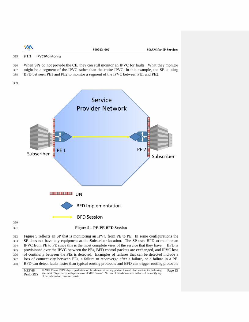
8.1.3 IPVC Monitoring 385
When SPs do not provide the CE, they can still monitor an IPVC for faults. What they monitor 386
might be a segment of the IPVC rather than the entire IPVC. In this example, the SP is using 387
BFD between PE1 and PE2 to monitor a segment of the IPVC between PE1 and PE2. 388
389
390
Figure 5 – PE-PE BFD Session 391
Figure 5 reflects an SP that is monitoring an IPVC from PE to PE. In some configurations the 392
SP does not have any equipment at the Subscriber location. The SP uses BFD to monitor an 393
IPVC from PE to PE since this is the most complete view of the service that they have. BFD is 394
provisioned over the IPVC between the PEs, BFD control packets are exchanged, and IPVC loss 395
of continuity between the PEs is detected. Examples of failures that can be detected include a 396
loss of connectivity between PEs, a failure to reconverge after a failure, or a failure in a PE. 397
BFD can detect faults faster than typical routing protocols and BFD can trigger routing protocols 398

S69013_002 SOAM for IP Services
MEF 66
Draft (R2)
© MEF Forum 2019. Any reproduction of this document, or any portion thereof, shall contain the following
statement: "Reproduced with permission of MEF Forum." No user of this document is authorized to modify any
of the information contained herein.
Page 14
to reconverge reestablishing connectivity. To reconverge at least two paths need to exist be-399
tween the PEs. If the SP has other protection mechanisms at lower levels, the BFD timer inter-400
vals need to take into account protection mechanism timers at these lower levels to ensure that 401
the lower levels act before the BFD timer triggers a reconvergence. 402
8.2 FM Tool Requirements 403
As stated previously, BFD is being specified as the primary Proactive FM tool. ICMP ping and 404
traceroute are specified as On-demand tools. This section of the document specifies the re-405
quirements that must be supported for each of these tool sets. 406
8.2.1 Proactive Monitoring 407
BFD is specified in IETF RFC 5880 [11]. Additional details on BFD intervals are specified in 408
IETF RFC 7419 [14]. See RFC 5880 [11] for a detailed description of the BFD protocol and its 409
operation. When proactively monitoring a single hop, BFD is implemented as described in RFC 410
5881 [12]. When proactively monitoring multihop services, BFD is implemented as described in 411
RFC 5883 [13]. 412
413
8.2.1.1 BFD Overview 414
Per RFC 5880 [11] BFD is intended to detect faults in the bidirectional path between two for-415
warding engines, including interfaces, data link(s), and to the extent possible the forwarding en-416
gines themselves, with potentially very low latency. BFD is a more efficient method to quickly 417
detect and notify registered protocols that a failure has occurred. This means individual control 418
protocols "hello" timers need not be configured individually and aggressively. They can rely on 419
BFD for failure notification. 420
BFD operates between a pair of systems that are exchanging BFD packets. If a system stops re-421
ceiving BFD packets for some specified period of time, the path is declared failed. A path is on-422
ly declared up when properly constructed BFD packets are received at each system in the pair. 423
The time interval between the transmission of two consecutive BFD packets is negotiated be-424
tween the two BFD systems. Because of random jitter of BFD packet transmission, average in-425
terval between two packets equals 0.875 of the negotiated value. RFC 7419 [14] provides rec-426
ommendations on time intervals that are supported by all systems to make the negotiation pro-427
cess easier. Once the time interval is determined, RFC 5880 [11] defines two modes for BFD, 428
Asynchronous and Demand. For FM Proactive monitoring, this document focuses on Asynchro-429
nous. Asynchronous mode provides a more proactive solution for monitoring for faults than 430
Demand mode and can provide faster fault detection that a Demand session with the same trans-431
mission interval. The Echo function is an adjunct to both modes and allows one system to 432
transmit BFD packets and the other systems loops them back through its forwarding path. While 433
this can reduce the processing requirements to one end, it does add additional packets to the net-434
work. 435
Note: Echo function cannot be used with mulithop BFD specified in RFC 5883 [13]. 436

S69013_002 SOAM for IP Services
MEF 66
Draft (R2)
© MEF Forum 2019. Any reproduction of this document, or any portion thereof, shall contain the following
statement: "Reproduced with permission of MEF Forum." No user of this document is authorized to modify any
of the information contained herein.
Page 15
Authentication can be supported by BFD to limit the ability of false packets to impact the for-437
warding paths. Authentication methods range from a simple password to MD5 and SHA1 au-438
thentication. 439
8.2.1.2 BFD Support 440
This section details requirements for network elements supporting BFD. BFD is defined in 441
RFC 5880 [11]. RFC 5881 [12] and RFC 5883 [13] also apply for some implementations. 442
Where support for a RFC is mandated, unless otherwise stated, all required and recommended 443
requirements apply as stated in the RFC. 444
[R1] A BFD Implementation MUST comply with RFC 5880 [11] if BFD is sup-445
ported. 446
[R2] A BFD Implementation MUST comply with RFC 5881 [12] if single hop 447
BFD is supported. 448
[R3] A BFD Implementation MUST comply with RFC 5883 [13] if multi-hop 449
BFD is supported. 450
Support for Demand mode, as specified in RFC 5880 section 6.6 [11], is optional. RFC 5880 451
[11] section 6.8.15 describes how the BFD implementation responds to a forwarding plane reset. 452
RFC 7419 [14] describes issues with negotiating BFD transmission intervals. To resolve these 453
issues, it specifies a minimum list of common intervals that are to be supported. 454
[R4] A BFD implementation MUST support the following common intervals, 455
100ms, and 1 second as specified in RFC 7419 [14]. 456
[D1] Other intervals specified in RFC 7419 [14], 3.3ms, 10ms, 20ms, 50ms, 10 457
seconds SHOULD be supported. 458
[R5] A BFD implementation MUST support a Detect multiplier of 3. 459
[D2] A BFD implementation SHOULD support a Detect multiplier range of 2-255 460
[R6] A BFD implementation that supports an interval in the list of 3.3ms, 10ms, 461
20ms, and 50ms MUST support all longer intervals in that list as specified in 462
RFC 7419 [14]. 463
Additional BFD transmission intervals can be supported. 464
[R7] An IP SOAM Implementation MUST support a mechanism to limit the num-465
ber of IP SOAM FM packets processed per second. 466
As described previously a BFD implementation can be used to monitor either the Service Pro-467
vider’s network or services provided by the Service Provider for faults. Each of these might re-468
quire that the IP Data Service packets containing the BFD packets be treated differently by the 469
network devices. For this reason, the ability to set the DSCP value of the IP Data Service pack-470

S69013_002 SOAM for IP Services
MEF 66
Draft (R2)
© MEF Forum 2019. Any reproduction of this document, or any portion thereof, shall contain the following
statement: "Reproduced with permission of MEF Forum." No user of this document is authorized to modify any
of the information contained herein.
Page 16
ets is required. The Service Provider might want to match the value of a Subscriber’s service 471
and use a different value for their network. The following requirements support these features. 472
[R8] An IP SOAM Implementation MUST support the ability to set the DSCP val-473
ue of IP Data Service packets containing BFD packets. 474
[R9] The default value for the DSCP value MUST be 48. 475
476
8.2.2 On-Demand Fault Monitoring 477
On-demand fault monitoring uses Internet Control Message Protocol (ICMP) ping and trac-478
eroute. ICMP ping and traceroute use functions that are defined in RFC 792 [1] for IPv4 and 479
RFC 4443 [8] for IPv6. 480
On-demand Fault Management for IPv4 is done using the Echo/Echo Reply and Time Exceeded 481
messages defined in IETF RFC 792 [1]. This RFC defines widely deployed ICMP messages and 482
header formats. On-demand Fault Management for IPv6 is done using the Echo Request/Echo 483
Reply and Time Exceeded messages defined in IETF RFC 4443 [8]. This RFC defines widely 484
deployed ICMP messages and header formats. 485
[R10] An On-demand Fault Monitoring implementation supporting IPv4 MUST 486
comply with the requirements and message formats for Echo Request, Echo 487
Reply, and Time Exceeded Messages as specified in RFC 792. 488
[R11] An On-demand Fault Monitoring implementation supporting IPv4 MUST 489
support a unicast DA. 490
[R12] An On-demand Fault Monitoring implementation supporting IPv4 MUST 491
NOT support a multicast DA. 492
[R13] An On-demand Fault Monitoring implementation supporting IPv6 MUST 493
comply with the requirements and message formats for Echo Request, Echo 494
Reply and Time Exceeded Messages as specified in RFC 4443. 495
[R14] An On-demand Fault Monitoring implementation supporting IPv6 MUST 496
support a unicast DA. 497
[R15] An On-demand Fault Monitoring implementation supporting IPv6 MUST 498
NOT support a multicast DA. 499
[R16] An On-demand Fault Monitoring implementation of ping MUST support a 500
time interval between the transmissions of Echo Request messages of 1 sec-501
ond. 502
[D3] An On-demand Fault Monitoring implementation of ping SHOULD support a 503
time interval between the transmissions of Echo Request messages of 100ms. 504

S69013_002 SOAM for IP Services
MEF 66
Draft (R2)
© MEF Forum 2019. Any reproduction of this document, or any portion thereof, shall contain the following
statement: "Reproduced with permission of MEF Forum." No user of this document is authorized to modify any
of the information contained herein.
Page 17
[R17] An On-demand Fault Monitoring implementation of ping MUST allow the 505
number of Echo Request messages to be transmitted to be selected by the us-506
er. 507
[R18] An On-demand Fault Monitoring implementation of ping MUST be capable 508
of transmitting Echo Request messages indefinitely. 509
[R19] An On-demand Fault Monitoring implementation of ping MUST allow the 510
user to stop the transmission of Echo Request. 511
[R20] An On-demand Fault Monitoring implementation of traceroute MUST sup-512
port the transmission of Echo Request messages to a unicast DA. 513
[R21] An On-demand Fault Monitoring implementation of traceroute MUST sup-514
port the reception of Echo Reply messages from unicast addresses other than 515
the target DA. 516
[R22] An On-demand Fault Monitoring implementation of traceroute MUST sup-517
port reporting the IP addresses and TTL for each Echo Reply message re-518
ceived. 519
[R23] An On-demand Fault Monitoring implementation MUST allow the user to se-520
lect the length of transmitted ICMP PDU. 521
[R24] An On-demand Fault Monitoring implementation of ping MUST support 522
packet lengths of Echo Request message in the range of 64-1500 Bytes. 523
[D4] An On-demand Fault Monitoring implementation of ping SHOULD support 524
packet lengths of Echo Request message in the range of 1501-10000 Bytes. 525
Recommended default settings are shown in Table 3. 526
527
On-Demand Tool Recommended Default Comments
ICMP Ping Number of Echo Re-
quest Messages Trans-
mitted
3
Echo Request Message
Transmission Time In-
terval
1 second
Echo Request Message
Length
64 Bytes
ICMP Trac- Echo Request Message 1 second

S69013_002 SOAM for IP Services
MEF 66
Draft (R2)
© MEF Forum 2019. Any reproduction of this document, or any portion thereof, shall contain the following
statement: "Reproduced with permission of MEF Forum." No user of this document is authorized to modify any
of the information contained herein.
Page 18
eroute Transmission Time In-
terval
Echo Request Message
Length
64 Bytes
Table 3 - On-demand Tool Recommended Defaults 528
SPs can use other on-demand tools such as TCP ping or HTTP ping in their networks. The use 529
of these tools is outside the scope of the document. 530
8.3 FM Reporting 531
The requirements for reporting of faults detected by Fault Monitoring for Proactive monitoring 532
are described below. 533
[R25] FM implementations MUST support the ability to generate a notification to 534
the SOF/ICM within 2 seconds of a fault being detected by an FM session. 535
[R26] A fault notification MUST contain the following attributes: 536
Date and Time of the fault 537
Source IP Address 538
Destination IP Address 539
FM Session ID if assigned by SOF 540
Notification Type 541
Notification Severity 542
Notification Description 543
[D5] An FM implementation SHOULD support synchronization of the local time-544
of-day clock with UTC to within one second of accuracy. 545
The Date and Time represent the Date and Time of the fault state change in UTC with millisec-546
ond granularity and comply with [D5] for accuracy. 547
The Source and Destination IP addresses are specified at the creation of the BFD session. These 548
are transmitted in the measurement packets. 549
The FM Session ID can be assigned by the SOF upon the creation of the BFD session. This ID 550
is not transmitted within any measurement packets and is used only by the SOF to identify an 551
FM session. 552

S69013_002 SOAM for IP Services
MEF 66
Draft (R2)
© MEF Forum 2019. Any reproduction of this document, or any portion thereof, shall contain the following
statement: "Reproduced with permission of MEF Forum." No user of this document is authorized to modify any
of the information contained herein.
Page 19
The fault Notification Type is either SET or CLEAR. A SET is sent with all severities of notifi-553
cations. A CLEAR is not sent with Informational Notifications. 554
The fault Notification Severity is either, Critical, Major, Minor, or Informational and is used to 555
indicate the severity of the notification. 556
The fault Notification Description provides a textual description of the fault. 557
[R27] An FM implementation MUST support the ability to enable or disable notifi-558
cation of faults on a per FM session basis. 559
[R28] An FM implementation MUST support the ability to define the severity of a 560
fault report. 561
[R29] An FM implementation MUST support at least two fault report severities, 562
Critical and Major. 563
[O1] An FM implementation MAY support additional fault report severities. 564
The requirements for reporting of On-demand tools are described below. 565
[R30] A FM implementation of an ICMP Ping MUST report the following: 566
Number of TX packets 567
Number of RX packets 568
Minimum Round Trip Delay 569
Average Round Trip Delay 570
Maximum Round Trip Delay 571
Count of lost packets 572
Percentage of lost packets 573
[R31] A FM implementation of an ICMP Traceroute MUST report the following for 574
each response received to the ICMP Echo Request: 575
IP Address 576
Time to Live 577
Round Trip Delay 578
579
580

S69013_002 SOAM for IP Services
MEF 66
Draft (R2)
© MEF Forum 2019. Any reproduction of this document, or any portion thereof, shall contain the following
statement: "Reproduced with permission of MEF Forum." No user of this document is authorized to modify any
of the information contained herein.
Page 20
9 Performance Management 581
Performance Management (PM) provides the ability to measure the performance of IP Services. 582
This section contains the Use Cases, Tool Requirements, and Deployment Guidelines for PM for 583
IP Services. 584
9.1 PM Use Cases 585
Degradations in performance can have a greater impact on customer’s perception of network 586
quality than faults. Most networks have failover mechanisms that provide protection in the event 587
of a fault. In many cases, degradations do not cause these mechanisms to engage. As a result, 588
customer packets may continue to be transported over degraded facilities, leading to retransmis-589
sions or excessive delay. 590
MEF 61.1 defines an IPVC Service Level Specification Attribute that allows objectives to be 591
specified for a number of Performance Metrics such as One-way Mean Packet Delay and One-592
way Packet Loss Ratio. The performance objectives specified in the SLS are a commitment by 593
the SP to the Subscriber of how the service is expected to perform and can result in SPs issuing 594
rebates to Subscribers if SLS objectives are not met. 595
PM uses several terms that need to be understood. 596
The first is SLS Reference Point (SLS-RP). This is defined in MEF 61.1 [33] as a point 597
from or to which performance objectives are specified as part of an SLS; either an IPVC 598
End Point or a location specified in the SLS Service Attribute. 599
The second is Measurement Point (MP). An MP is defined within this document as a 600
point from or to which performance is measured. An MP can be at an IPVC End Point or 601
at a location specified by the SP. An MP is assigned an IP address and IP packets are 602
routed between the IP addresses of two MPs. There are two types of MPs, Controller and 603
Responder. A Controller MP is the MP that initiates SOAM PM Packets and receives re-604
sponses from the Responder MP. A Responder MP is the MP that receives SOAM PM 605
Packets from the Controller MP and transmits responses to the Controller MP. It should 606
be noted that SLS-RP and MP of the same service and directionality, i.e., “from” or “to”, 607
may be co-located or placed in different points along the path of the service. 608
The third term is an MP Pair. An MP Pair is a set of a particular Controller MP and a par-609
ticular Responder MP that are measuring performance. An example is two MPs each lo-610
cated at different IPVC End Points of the same IPVC that are measuring performance be-611
tween them. This MP Pair reports the performance between these two MPs as a part of 612
the performance for the entire IPVC. An MP is a part of one or more MP Pairs. 613
The fourth term is a PM Session. A PM Session is initiated on a Controller MP to take 614
performance measurements for a given SOAM PM IP Traffic Class and a given Re-615
sponder MP. 616

S69013_002 SOAM for IP Services
MEF 66
Draft (R2)
© MEF Forum 2019. Any reproduction of this document, or any portion thereof, shall contain the following
statement: "Reproduced with permission of MEF Forum." No user of this document is authorized to modify any
of the information contained herein.
Page 21
The fifth term is Measurement Interval. Measurement Intervals (MI) are discrete, non-617
overlapping periods of time during which the PM Session measurements are performed 618
and results are gathered. 619
The sixth term is PM Tool. PM Tools are the functionalities or implementations that are 620
used to perform the SOAM measurements. PM Tools are limited to TWAMP Light, 621
STAMP, and TWAMP. 622
Where the term PE is used in these figures this could represent a traditional PE, or a de-623
vice or an application managed by the SP providing some or all of PE functionality. 624
625
Figure 6 – SLS-RPs, MPs and Pair of MPs 626
Comment [MB1]: Make sure spelled out already

S69013_002 SOAM for IP Services
MEF 66
Draft (R2)
© MEF Forum 2019. Any reproduction of this document, or any portion thereof, shall contain the following
statement: "Reproduced with permission of MEF Forum." No user of this document is authorized to modify any
of the information contained herein.
Page 22
Figure 6 shows a single IPVC. The SLS-RPs and MPs are located at the UNIs. Three Pairs of 627
MPs are shown in blue, purple and orange. SOAM PM packets are exchanged between the MPs 628
in each Pair of MPs. 629
SPs normally approach monitoring the performance of their services and network in one of two 630
methods. In the first method, they identify IPVC End Points as SLS-RPs and configure MPs at 631
each IPVC End Point including the entire path of the service in their SLS. In the second method, 632
they designate SLS-RPs at some location, configure MPs at these locations, and measure per-633
formance between these MPs. Often with the second method there is an IPVC-like connection 634
also known as an IP-PMVC (IP-Performance Monitoring Virtual Connection) dedicated to 635
measuring the performance of connections between locations rather than monitoring specific 636
Subscriber IPVCs. The difference between these is shown in Figure 7. Note that in both of these 637
methods; MPs are created at the points in the network between which the SLS objectives are 638
specified, i.e. in the same places as the SLS-RPs. This provides the most direct way of measur-639
ing performance so as to determine whether the objectives specified in the SLS have been met. 640
However, it is not required that MPs and SLS-RPs are in the same places, and other arrange-641
ments are possible. 642

S69013_002 SOAM for IP Services
MEF 66
Draft (R2)
© MEF Forum 2019. Any reproduction of this document, or any portion thereof, shall contain the following
statement: "Reproduced with permission of MEF Forum." No user of this document is authorized to modify any
of the information contained herein.
Page 23
643
Figure 7 – SLS Method 1 and Method 2 Comparison 644
Examples of possible locations of the MPs are shown in Figure 8. 645

S69013_002 SOAM for IP Services
MEF 66
Draft (R2)
© MEF Forum 2019. Any reproduction of this document, or any portion thereof, shall contain the following
statement: "Reproduced with permission of MEF Forum." No user of this document is authorized to modify any
of the information contained herein.
Page 24
646
Figure 8 - Example MP Locations 647
PM can be performed using one of these three mechanisms: 648
active method where synthetic packets are generated and measurements are performed on 649
these packets 650
passive method where counters reflecting customer traffic are retrieved from network el-651
ements 652
hybrid method where customer traffic is modified to allow performance measurements to 653
be performed using customer packets 654

S69013_002 SOAM for IP Services
MEF 66
Draft (R2)
© MEF Forum 2019. Any reproduction of this document, or any portion thereof, shall contain the following
statement: "Reproduced with permission of MEF Forum." No user of this document is authorized to modify any
of the information contained herein.
Page 25
This document focuses on active PM measurement and discusses hybrid PM measurement. Pas-655
sive PM measurement is outside the scope of the document. This is because the retrieval of net-656
work element counters is implementation specific. Future versions of this document might ad-657
dress passive PM measurement if the retrieval of these counters is standardized. 658
Within this document, Active Measurement is specified as using TWAMP 659
Light/STAMP/TWAMP. These PM tools are defined in RFC 5357 [10] and IETF Draft draft-660
ietf-ippm-stamp [20]. They enable Single-Ended monitoring of packet delay and packet loss. 661
The protocol defined for each of these PM tools has a Session-Sender (Controller MP) and a Ses-662
sion-Reflector (Responder MP). The Controller MP generates measurement packets. The Re-663
sponder MP responds to these packets. Time stamps in the packets allow one-way delay meas-664
urements to be performed if Time of Day (ToD) clock synchronization is present. If ToD syn-665
chronization is not present, it is not possible to make One-way delay measurements. Two-way 666
delay measurements are possible and Two-way delay measurements can be divided in half as 667
long as the results are identified as derived. 668
Hybrid Measurement is described using the AltM method. AltM is defined in RFC 8321 [17]. 669
AltM enables Single-Ended monitoring for One-way Packet Delay and Packet Loss. See Section 670
10 for informational text on AltM. 671
PM Tools that measure Packet Delay (PD) and Packet Loss (PL) can be used to calculate addi-672
tional metrics. PD measurements are used to calculate Mean Packet Delay, Inter-Packet Delay 673
Variation, and Packet Delay Range. PL, measured as the difference between the number of 674
transmitted packets and the number of packets received, is used to calculate the Packet Loss Ra-675
tio (PLR). 676
The following sections detail the use cases for PM including Location to Location monitoring 677
and UNI to UNI monitoring. Location to Location monitoring provides a view of performance 678
between locations using an IPVC-like connection but does not monitor any Subscriber IPVCs in 679
a SP’s network. UNI to UNI monitoring provides a view of the performance of a Subscriber 680
IPVC from UNI to UNI. 681
9.1.1 Location to Location Monitoring 682
One way of monitoring performance by SPs is to monitor network performance from Location to 683
Location via a single PE at each Location. As such, individual IPVCs are not monitored. Loca-684
tions are connected together using a Network Measurement IPVC-like connection called an IP-685
Performance Monitoring Virtual Connection (IP-PMVC). This SLS monitoring via the Network 686
Measurement IPVC-like connection between Locations provides an indication of the perfor-687
mance of the SPs network between the Locations. Authentication might be used to provide se-688
cure communications in TWAMP and STAMP implementations. If Active Measurement is be-689
ing used the packets are routed over the Network Measurement IPVC-like connection that con-690
nects the Locations together. The measurement packets on the Network Measurement IPVC-like 691
connection are expected to be treated similar to Subscriber packets. Service Providers need to 692
ensure that they take into account network techniques such as Traffic Engineering (TE) and 693
Equal Cost Multi Path (ECMP) routing when designing the operation of IP-PMVCs. Packet loss 694

S69013_002 SOAM for IP Services
MEF 66
Draft (R2)
© MEF Forum 2019. Any reproduction of this document, or any portion thereof, shall contain the following
statement: "Reproduced with permission of MEF Forum." No user of this document is authorized to modify any
of the information contained herein.
Page 26
or delay that is measured between each location approximates the performance experienced by 695
the Subscriber. 696
697
Figure 9 – Active PM Location to Location via IP-PMVC 698
Figure 9 is an example of a SP monitoring the performance of their network from Location to 699
Location using an IP-PMVC dedicated to monitoring. The Locations are defined by the SP and 700
interconnected using the IP-PMVC. An IP SOAM Implementation, either purpose built hard-701
ware, an application running in in a Virtual Machine (VM) on external hardware or an applica-702
tion running in the device at the location capable of generating measurement packets is connect-703
ed to the SP network, sometimes via a UNI-like connection, and measurement packets are trans-704
mitted between all of the Locations via MPs that in this case are also IP-PMVC EPs. An MP can 705
be the same point as the SLS-RP as shown in the figure but does not have to be the same point. 706
Data collection is performed for some or all Pair of MPs. 707
An IP-PMVC is an IPVC-like connection between locations and is used for PM. The IP-PMVC 708
can be routed similar to subscriber IPVCs. The IP-PMVC has EPs that are similar to an IPVC 709
EP. A Location could represent a portion of a city, city, a country, a region or some other entity. 710
A pair of MPs might include PM reports for multiple CoS Names that are monitored between the 711
Locations. Subscribers who have IPVCs that connect between those entities might use the PM 712
reports as an indication if the performance of their IPVCs has met the SLS. Within the SLS 713

S69013_002 SOAM for IP Services
MEF 66
Draft (R2)
© MEF Forum 2019. Any reproduction of this document, or any portion thereof, shall contain the following
statement: "Reproduced with permission of MEF Forum." No user of this document is authorized to modify any
of the information contained herein.
Page 27
some Location Pairs might have different performance objectives than others. The SLS perfor-714
mance objectives that apply to one pair of MPs might be different than the SLS performance ob-715
jectives that apply to another pair of MPs. This is because the expected performance between 716
some cities, countries, or regions differs. Some Locations might offer higher performance SLS 717
performance objectives while others offer lower performance SLS performance objectives. 718
In general, degradations that impact the Subscriber packets also impact the IP SOAM Perfor-719
mance monitoring packets. 720
9.1.2 IPVC Monitoring 721
Another method of PM for an IP service is to monitor the IPVC. This method might include the 722
entire path of the service or some portion of it. Examples are from IPVC EP to IPVC EP or 723
monitoring some portion of the IPVC. The SP is able to monitor degradations that occur at any 724
point in the IPVCs between the two Measurement Points (MPs). This provides a more compre-725
hensive view of the Subscriber’s service performance. Using Active Measurement to perform 726
IPVC monitoring requires that the PM packets be carried on the Subscriber’s IPVC. 727
728

S69013_002 SOAM for IP Services
MEF 66
Draft (R2)
© MEF Forum 2019. Any reproduction of this document, or any portion thereof, shall contain the following
statement: "Reproduced with permission of MEF Forum." No user of this document is authorized to modify any
of the information contained herein.
Page 28
729
Figure 10 – IPVC EP to IPVC EP Active Measurement 730
Figure 10 is an example of Active Measurement on an IPVC from IPVC EP to IPVC EP. In this 731
example, the IPVC EP, SLS-RP, and MP are all co-located. IP SOAM PM Implementations are 732
deployed with the IPVC EPs. The IP SOAM PM Implementations are capable of generating 733
monitoring packets. Packets are exchanged between all MPs active on the IPVC. Measurements 734
between each Pair of MPs are made and collected. 735
736
737

S69013_002 SOAM for IP Services
MEF 66
Draft (R2)
© MEF Forum 2019. Any reproduction of this document, or any portion thereof, shall contain the following
statement: "Reproduced with permission of MEF Forum." No user of this document is authorized to modify any
of the information contained herein.
Page 29
738
Figure 11 – Active Measurement when MPs are not at – IPVC EPs 739
Figure 11 shows monitoring of an IPVC that places the MPs at some point other than the IPVC 740
EP. This is similar to Location to Location monitoring as shown in section 9.1.1 but monitoring 741
is per Subscriber IPVC versus an IP-PMVC dedicated to monitoring. This type of monitoring 742
requires support for MPs and IP SOAM Implementations at some point within the Service Pro-743
vider’s network. 744
While monitoring each IPVC has some definite benefits, it also has some challenges. IPVC 745
monitoring requires that either that all IPVC EPs within an IPVC support both an MP and an IP 746
SOAM PM Implementation, or that some points in the SP’s network do so. This requires instan-747
tiation of many IP SOAM Implementations which can use processing capacity at each location. 748
This differs from Location to Location monitoring where only one or two IP-PMVC EPs per Lo-749
cation need to instantiate MPs and IP SOAM PM Implementations as shown in section 9.1.1. 750
This limits the processing capacity required. 751
An IP SOAM PM Implementation might be able to be supported as a part of a device supporting 752
the CE, PE, or other function rather than be a separate device as shown in the figures. Monitor-753

S69013_002 SOAM for IP Services
MEF 66
Draft (R2)
© MEF Forum 2019. Any reproduction of this document, or any portion thereof, shall contain the following
statement: "Reproduced with permission of MEF Forum." No user of this document is authorized to modify any
of the information contained herein.
Page 30
ing per IPVC EP increases the probe count compared to Location to Location monitoring and 754
therefore increases the amount of data that must be processed. 755
A means to communicate between the ICM/ECM and the IP SOAM Implementation instantiated 756
in the network is required. This can be accomplished via in-band or out-of-band methods. There 757
are impacts of either of these communication methods. In-band communication could require 758
additional bandwidth be provisioned to the device and out-of-band communication could require 759
an additional service be configured to the device for communication. With Location to Location 760
monitoring, this is limited to one or two probes versus bandwidth to every IPVC EP. 761
The functionality described above allows monitoring the performance between all IPVC EPs of 762
an IPVC, between some subset of IPVC EPs, between IPVC EPs and MPs that are not at the 763
IPVC EPs, and between any combination of these. These can be reflected as CE to PE, CE to 764
CE, or PE to PE in more common terms. 765
9.2 PM Common Requirements 766
This section provides requirements that are applicable to PM. The requirements below provide 767
for the Life Cycle (starting, stopping, etc.) and Storage. 768
Many requirements apply to an “IP SOAM PM Implementation”, which refers to the capabilities 769
of a device or virtual function that are required to support IP SOAM Performance Monitoring. 770
9.2.1 Life Cycle 771
The requirements of this section apply to the life cycle of a PM Session, and to the scheduling of 772
performance measurements conducted as part of a PM Session. Specifically, scheduling controls 773
when, how long, and how often measurements will be taken for a PM Session. 774
9.2.1.1 General Overview of Parameters 775
The Performance Monitoring process is made up of a number of Performance Monitoring in-776
stances, known as PM Sessions. A PM Session is initiated on a Controller MP to take perfor-777
mance measurements for a given SOAM PM IP CoS Name and a given Responder MP. A PM 778
Session is used for Loss Measurement and Delay Measurement. 779
The PM Session is specified by several direct and indirect parameters. A general description of 780
these parameters is listed below, with more detailed requirements provided elsewhere in the doc-781
ument. 782
The End Points are the Controller MP and a Responder MP. 783
The DSCP used for the PM Session is chosen such that the performance of measurement 784
packets is representative of the performance of the Qualified Packets being monitored. 785
The PM Tool is any of the tools described in section 9.2 (TWAMP Light, STAMP, or 786
TWAMP). 787

S69013_002 SOAM for IP Services
MEF 66
Draft (R2)
© MEF Forum 2019. Any reproduction of this document, or any portion thereof, shall contain the following
statement: "Reproduced with permission of MEF Forum." No user of this document is authorized to modify any
of the information contained herein.
Page 31
The Message Period is the SOAM PM Packet transmission frequency (the time between 788
SOAM PM Packet transmissions). 789
The Start Time is the time that the PM Session begins. 790
The Stop Time is the time that the PM Session ends. 791
The Measurement Intervals are discrete, non-overlapping periods of time during which 792
the PM Session measurements are performed and results are gathered. SOAM PM pack-793
ets for a PM Session are transmitted only during a Measurement Interval. Key character-794
istics of Measurement Intervals are the alignment to the clock and the duration of the 795
Measurement Interval. Measurement Intervals can be aligned to either the PM Session 796
Start Time or to a clock, such as the local time-of-day clock. The duration of a Measure-797
ment Interval is the length of time spanned by a non-truncated Measurement Interval. 798
The Repetition Time is the time between the start times of the Measurement Intervals. 799
9.2.1.2 Proactive and On-Demand PM Sessions 800
A PM Session can be classified as either a Proactive or an On-demand session. A Proactive ses-801
sion is intended to perpetually measure the performance between the MPs for the given SOAM 802
PM IP CoS Name. An On-demand session is intended to monitor the performance for some finite 803
period of time. 804
A Proactive session runs all the time once it has been created and started. Since the intent is to 805
provide perpetual performance measurement, Proactive sessions use a Start Time of “immediate” 806
and a Stop Time of “forever”. Measurements are collected into multiple fixed length Measure-807
ment Intervals covering different periods of time. Measurement Intervals for Proactive sessions 808
are generally aligned to a clock, rather than the Session Start Time. Data is collected and a histo-809
ry of data is stored for a number of Measurement Intervals. Monitoring continues until the PM 810
Session is deleted. 811
On-demand sessions are run when needed, and a report is provided at the end. Since On-demand 812
sessions are intended to cover some finite period of time, absolute or relative Start and Stop 813
Times may be used if those values are known. Alternatively, a Start Time of “immediate” and/or 814
a Stop Time of “forever” may be used (with the intention of manually ending the session when 815
no longer needed), especially if the monitoring period is of unknown duration (e.g., “until trou-816
bleshooting is completed”.) Measurements may be gathered into one Measurement Interval 817
spanning the entire session duration, or multiple Measurement Intervals covering different peri-818
ods of time. When multiple Measurement Intervals are used, then historical data from past 819
Measurement Intervals may or may not be stored on the device. In addition, Measurement Inter-820
vals may be aligned with the session Start Time or aligned with a clock. 821
9.2.1.3 Create 822
A PM Session has to be created before it can be started. This applies for both On-demand and 823
Proactive PM Sessions. In order to create a PM Session, a PM Tool must be assigned to the PM 824
Session. 825

S69013_002 SOAM for IP Services
MEF 66
Draft (R2)
© MEF Forum 2019. Any reproduction of this document, or any portion thereof, shall contain the following
statement: "Reproduced with permission of MEF Forum." No user of this document is authorized to modify any
of the information contained herein.
Page 32
[D6] An IP SOAM PM Implementation SHOULD support multiple concurrent PM 826
Sessions to the same destination, regardless of the setting of other parameters 827
for the PM Sessions, and regardless of whether the PM Sessions use the same 828
or different PM Tools using the five tuple (destination and source IP address-829
es, transport type, and destination and source port numbers) to identify each 830
PM Session. 831
Multiple PM Sessions using the same PM Tool could be used, for example, to monitor different 832
SOAM PM IP CoS Name (and hence measure performance for different IP CoS Name packets), 833
different packet lengths, or to support both Proactive and On-demand sessions. 834
[R32] An IP SOAM PM Implementation MUST provide a way to indicate to the 835
ICM/SOF whether a PM Session is Proactive or On-demand. 836
9.2.1.4 Delete 837
The requirements of this section apply to the deletion of a PM Session. 838
[R33] An IP SOAM PM Implementation MUST support the capability to delete a 839
PM Session. 840
[R34] After a PM Session is deleted, further IP SOAM PM Packets relating to the 841
session MUST NOT be sent. 842
[R35] After a PM Session is deleted, further measurements associated with the de-843
leted PM Session MUST NOT be made. 844
[O2] Before the data from a deleted PM Session is lost, an IP SOAM PM Imple-845
mentation MAY issue a report (similar to the report that would happen when 846
Stop Time is reached). 847
[R36] After a PM Session is deleted, all the stored measurement data relating to the 848
deleted PM Session MUST be deleted. 849
Note: a PM Session may be deleted at any point in its lifecycle, including before it has started. 850
9.2.1.5 Start and Stop 851
When a PM Session is started, it can be specified to start immediately, or be scheduled to start in 852
the future. Both start conditions, particularly “immediate”, are conditional upon the local inter-853
face reaching the operational Up state and the address associated with the Responder being 854
reachable. 855
[R37] For Proactive PM Sessions, the Start Time MUST be “immediate”. 856
[R38] For On-demand PM Sessions, an IP SOAM PM Implementation MUST sup-857
port a configurable Start Time per PM Session. The Start Time can be speci-858
fied as “immediate”, as an offset from the current time, or as a fixed absolute 859
time in the future. 860

S69013_002 SOAM for IP Services
MEF 66
Draft (R2)
© MEF Forum 2019. Any reproduction of this document, or any portion thereof, shall contain the following
statement: "Reproduced with permission of MEF Forum." No user of this document is authorized to modify any
of the information contained herein.
Page 33
An offset from the current time (i.e., a "relative" time) could be specified as a given number of 861
hours, minutes, and seconds from the current time. A fixed absolute time could be specified as a 862
given UTC date and time. 863
[D7] For On-demand PM Sessions, the default Start Time SHOULD be “immedi-864
ate”. 865
The following requirements apply to stopping of a PM Session. 866
[R39] For Proactive PM Sessions, the Stop Time MUST be “forever”. 867
[R40] For On-demand PM Sessions, an IP SOAM PM Implementation MUST sup-868
port a configurable Stop Time per PM Session. The Stop Time can be speci-869
fied as “forever” or as an offset from the Start Time. 870
An offset from the current time (i.e., a “relative” time) could be specified as a given number of 871
hours, minutes, and seconds from the Start Time. 872
[R41] For On-demand PM Sessions, if the Stop Time is specified as an offset from 873
the Start Time, then the Stop Time MUST be equal to or greater than the 874
Message Period of the PM Session. 875
[D8] For On-demand PM Sessions, the default Stop Time SHOULD be "forever". 876
[R42] An IP SOAM PM Implementation MUST support stopping a PM Session by 877
management action, prior to the Stop Time being reached. 878
[R43] After a PM Session is stopped, whether by reaching the scheduled Stop Time 879
or by other means, further SOAM PM Packets relating to the session MUST 880
NOT be sent. 881
[R44] After a PM Session is stopped, the stored measurements relating to the PM 882
Session MUST NOT be deleted. 883
Note: a PM Session cannot be restarted once it has been stopped, as this would make it difficult 884
to interpret the results. Instead, a new PM Session can be started. 885
9.2.1.6 Measurement Intervals 886
For the duration of a PM Session, measurements are partitioned into fixed-length Measurement 887
Intervals. The length of the period of time associated with a Measurement Interval is called the 888
duration of the Measurement Interval. The results of the measurements are captured in a Meas-889
urement Interval Data Set. The results in a Measurement Interval Data Set are stored separately 890
from the results of measurements performed during other Measurement Intervals. This section 891
contains requirements pertaining to Measurement Intervals in the Life Cycle of the PM Session. 892
Requirements pertaining to storage of Measurement Interval Data Sets are found in section 893
9.2.2.1. 894

S69013_002 SOAM for IP Services
MEF 66
Draft (R2)
© MEF Forum 2019. Any reproduction of this document, or any portion thereof, shall contain the following
statement: "Reproduced with permission of MEF Forum." No user of this document is authorized to modify any
of the information contained herein.
Page 34
[R45] A SOAM PM Implementation MUST support a configurable duration for 895
Measurement Intervals. 896
[R46] A SOAM PM Implementation MUST support a Measurement Interval with 897
duration of 15 minutes for Proactive PM Sessions. 898
[R47] A SOAM PM Implementation MUST support Measurement Intervals with a 899
duration of between 1 minute and 15 minutes (in 1 minute increments) for 900
On-Demand PM Sessions. 901
[D9] The default Measurement Interval duration for On-Demand PM Sessions 902
SHOULD be 5 minutes. 903
9.2.1.7 Repetition Time 904
For each PM Session, a Repetition Time can be specified if it is not desirable to perform meas-905
urements continuously. If the Repetition Time is “none”, then a new Measurement Interval is 906
started immediately after the previous one finishes, and hence performance measurements are 907
made continuously. If a Repetition Time is specified, a new Measurement Interval is not started 908
until after Repetition Time has passed since the previous Measurement Interval started. During 909
the time between the end of the previous Measurement Interval and the start of the next one, no 910
SOAM PM Packets are sent by the Controller MP relating to the PM Session, and no measure-911
ments are initiated. Note that Responder MPs may send SOAM Packets during the time between 912
two Measurement Intervals in response to SOAM Packets that may have previously been sent by 913
the Controller MP. 914
[R48] An IP SOAM PM Implementation MUST support a configurable Repetition 915
Time per PM Session. The Repetition Time can be specified as “none” or as a 916
repeating time interval. 917
A repeating time interval (i.e., a relative time) could be specified as every given number of 918
hours, minutes, and seconds from the Start Time. 919
[D10] The default Repetition Time SHOULD be “none”. 920
[R49] If the Repetition Time is a relative time, the time specified MUST be greater 921
than the duration of the Measurement Interval. 922
[R50] During the time between two Measurement Intervals, SOAM PM Packets re-923
lating to the PM Session MUST NOT be sent by the Controller MP. 924
9.2.1.8 Alignment of Measurement Intervals 925
The following requirements pertain to the alignment of Measurement Intervals with time-of-day 926
clock or PM Session Start Time. 927
[D11] An IP SOAM PM Implementation SHOULD by default align the start of each 928
Measurement Interval, other than the first Measurement Interval, on a bound-929

S69013_002 SOAM for IP Services
MEF 66
Draft (R2)
© MEF Forum 2019. Any reproduction of this document, or any portion thereof, shall contain the following
statement: "Reproduced with permission of MEF Forum." No user of this document is authorized to modify any
of the information contained herein.
Page 35
ary of the local time-of-day clock that is divisible by the duration of the 930
Measurement Interval (when Repetition Time is “none”). 931
[D12] An IP SOAM PM Implementation SHOULD by default align the start of each 932
Measurement Interval, other than the first Measurement Interval, on a bound-933
ary of the local time-of-day clock that is divisible by the Repetition Time 934
(when Repetition Time is not “none”). 935
When Measurement Intervals are aligned with the ToD clock, the Start Time of a PM Session 936
might not correspond with the alignment boundary. In this case, the first Measurement Interval 937
could be truncated. 938
[D13] An IP SOAM PM Implementation SHOULD allow for no alignment to the 939
ToD clock. 940
[D14] An IP SOAM PM Implementation SHOULD support a configurable (in 941
minutes) offset from ToD time for alignment of the start of Measurement In-942
tervals other than the first Measurement Interval. 943
For example, if the Measurement Interval is 15 minutes and the Repetition Time is “none” and if 944
ToD offset is 5 minutes, the Measurement Intervals would start at 5, 20, 35, 50 minutes past each 945
hour. 946
9.2.1.9 Summary of Time Parameters 947
Possible values for the time parameters are summarized in the table below and are further ex-948
plained in Appendix A: 949
950
Attribute Possible Values PM Session Type
Start Time “Immediate” (default)
ToD Offset
Relative Time
Fixed Time
Proactive or On-Demand
Proactive or On-Demand
On-Demand
On-Demand
Stop Time “Forever” (default)
Relative Time Proactive or On-Demand
On-Demand
Repetition Time “None”
Relative Time Proactive or On-Demand
Proactive or On-Demand
Table 4 – Time Parameters 951
9.2.2 Storage 952
The requirements of this section apply to storage of performance measurement results taken dur-953
ing Measurement Intervals, using counters or Measurement Bins (for some delay-related parame-954
ters). Performance measurements are stored separately for each Measurement Interval. A Meas-955
urement Bin is a counter, and records the number of performance measurements falling within a 956
specified range. 957

S69013_002 SOAM for IP Services
MEF 66
Draft (R2)
© MEF Forum 2019. Any reproduction of this document, or any portion thereof, shall contain the following
statement: "Reproduced with permission of MEF Forum." No user of this document is authorized to modify any
of the information contained herein.
Page 36
958
Figure 12 – Example of Measurement Bins and Intervals 959
Figure 12 shows the relationship between Measurement Bins and Measurement Intervals. Mul-960
tiple Measurement Bins can be configured for a PM Session. Counts in these bins are incre-961
mented during each Measurement Interval. 962
Only delay measurements use bins; for loss measurements, bins are not used. Instead, each 963
Measurement Interval contains counters that display Transmitted (TX) and Received (RX) pack-964
et counts. This is shown in Figure 13 below. 965

S69013_002 SOAM for IP Services
MEF 66
Draft (R2)
© MEF Forum 2019. Any reproduction of this document, or any portion thereof, shall contain the following
statement: "Reproduced with permission of MEF Forum." No user of this document is authorized to modify any
of the information contained herein.
Page 37
966
Figure 13 – Example of Packet Count Measurements 967
9.2.2.1 Measurement Interval Data Sets 968
The following requirements apply to the storage of the results of PD, PDR, MPD, IPDV, or PLR, 969
performance measurements conducted between a given source and destination pair of MPs, for a 970
given PM Session during a given Measurement Interval. 971
[R51] An IP SOAM PM Implementation MUST store measurement data for a cur-972
rent Measurement Interval and at least 8 hours of historic measurement data 973
(captured per Measurement Interval) for a given data set of a Proactive PM 974
Session. 975
[D15] An IP SOAM PM Implementation SHOULD store measurement data for a 976
current Measurement Interval and at least 24 hours of historic measurement 977
data (captured per Measurement Interval) for a given data set of a Proactive 978
PM Session. 979
[D16] An IP SOAM PM Implementation SHOULD store measurement data for a 980
current Measurement Interval and at least 8 hours of historic measurement 981
data (captured per Measurement Interval) for a given data set of an On-982
demand PM Session. 983

S69013_002 SOAM for IP Services
MEF 66
Draft (R2)
© MEF Forum 2019. Any reproduction of this document, or any portion thereof, shall contain the following
statement: "Reproduced with permission of MEF Forum." No user of this document is authorized to modify any
of the information contained herein.
Page 38
[R52] An IP SOAM PM Implementation MUST record the value of the local ToD 984
clock in UTC at the scheduled start of the Measurement Interval. 985
[R53] An IP SOAM PM Implementation MUST record the value of the local ToD 986
clock in UTC at the scheduled end of the Measurement Interval. 987
[R54] An IP SOAM PM Implementation MUST support an elapsed time counter 988
per Measurement Interval, which records the number of seconds that have 989
elapsed since the Measurement Interval began. 990
[D17] An IP SOAM PM Implementation SHOULD support synchronization of the 991
local time-of-day clock with UTC to within one second of accuracy. 992
[R55] An IP SOAM PM Implementation MUST record the results of a completed 993
performance measurement as belonging to the Measurement Interval Data Set 994
for the Measurement Interval in which the performance measurement was ini-995
tiated. 996
[R56] An implementation of SOAM PM MUST support configurable wait timer, 997
with the range of values from 1 second through to 5 seconds in one-second 998
increments and the default value of 5 seconds, associated with the end of the 999
Measurement Interval. 1000
[R57] For Single-Ended Functions, a SOAM PM response packet received by the 1001
Controller MP after the expiration of the associated wait timer after the end of 1002
the Measurement Interval in which the corresponding SOAM PM request 1003
packet was transmitted MUST be discarded and considered lost. 1004
9.2.2.2 Measurement Bins 1005
The following requirements apply to the use of Measurement Bins for recording the results of 1006
delay performance measurements which can be used to determine conformance to PD, IPDV, 1007
and PDR objectives conducted between a given source and destination MP for a given PM Ses-1008
sion during a Measurement Interval. Additional detail on Measurement Bins is provided in Ap-1009
pendix B. 1010
The following requirements apply to each PD measurement supported in an IP SOAM PM Im-1011
plementation. 1012
[R58] An IP SOAM PM Implementation MUST support a configurable number of 1013
PD Measurement Bins per Measurement Interval. 1014
[D18] For an IP SOAM PM Implementation, the default number of PD Measurement 1015
Bins per Measurement Interval SHOULD be 2. 1016
[R59] An IP SOAM PM Implementation MUST support at least 2 PD Measurement 1017
Bins per Measurement Interval. 1018

S69013_002 SOAM for IP Services
MEF 66
Draft (R2)
© MEF Forum 2019. Any reproduction of this document, or any portion thereof, shall contain the following
statement: "Reproduced with permission of MEF Forum." No user of this document is authorized to modify any
of the information contained herein.
Page 39
[D19] An IP SOAM PM Implementation SHOULD support at least 10 PD Meas-1019
urement Bins per Measurement Interval. 1020
The following requirements apply to each IPDV or PDR measurement supported in an IP SOAM 1021
PM Implementation. 1022
[R60] An IP SOAM PM Implementation MUST support a configurable number of 1023
IPDV Measurement Bins per Measurement Interval. 1024
[D20] For an IP SOAM PM Implementation, the default number of IPDV Measure-1025
ment Bins per Measurement Interval supported SHOULD be 2. 1026
[R61] An IP SOAM PM Implementation MUST support at least 2 IPDV Measure-1027
ment Bins per Measurement Interval. 1028
[D21] An IP SOAM PM Implementation SHOULD support at least 10 IPDV Meas-1029
urement Bins per Measurement Interval. 1030
[R62] An IP SOAM PM Implementation MUST support a configurable number of 1031
PDR Measurement Bins per Measurement Interval. 1032
[D22] For an IP SOAM PM Implementation, the default number of PDR Measure-1033
ment Bins per Measurement Interval supported SHOULD be 2. 1034
[R63] An IP SOAM PM Implementation MUST support at least 2 PDR Measure-1035
ment Bins per Measurement Interval. 1036
[D23] An IP SOAM PM Implementation SHOULD support at least 10 PDR Meas-1037
urement Bins per Measurement Interval. 1038
Note: For PDR the minimum PD for the MI is subtracted before binning the results. 1039
The following general Measurement Bin requirements apply to any IP SOAM PM Implementa-1040
tion. Each bin is associated with a specific range of observed delay, IPDV or PDR. Bins are de-1041
fined to be contiguous, and each is configured with its lower bound. Because the bins are contig-1042
uous, it is only necessary to configure the lower bound of each bin. Furthermore, the lowest bin 1043
is assumed to always have a lower bound of 0, and the highest bin is assumed to have an upper 1044
bound of ∞. 1045
Note: All values for IPDV, PDR and Two-way PD are positive by definition. Values for One-1046
way PD can be negative if there is no ToD synchronization, and such measurements would not 1047
match any Measurement Bin as defined above; however, in this case taking One-way PD meas-1048
urements is not recommended except for the purpose of finding the minimum PD for normaliza-1049
tion of PDR, and finding the minimum PD does not require Measurement Bins. 1050
A Measurement Bin is associated with a single counter that can take on non-negative integer 1051
values. The counter records the number of measurements whose value falls within the range rep-1052
resented by that bin. 1053

S69013_002 SOAM for IP Services
MEF 66
Draft (R2)
© MEF Forum 2019. Any reproduction of this document, or any portion thereof, shall contain the following
statement: "Reproduced with permission of MEF Forum." No user of this document is authorized to modify any
of the information contained herein.
Page 40
[R64] An IP SOAM PM Implementation MUST support a configurable lower 1054
bound for all but the first Measurement Bin. 1055
[R65] The lower bound for each Measurement Bin MUST be larger than the lower 1056
bound of the preceding Measurement Bin. 1057
[R66] The unit for a lower bound MUST be in microseconds (μs). 1058
[R67] The lower bound of the first Measurement Bin MUST be fixed to 0μs. 1059
[R68] Measured performance values that are greater than or equal to the lower 1060
bound of a given bin and strictly less than the lower bound of the next bin (if 1061
any), MUST be counted in that, and only that bin. 1062
[D24] The default lower bound for a Measurement Bin SHOULD be an increment 1063
of 5000 μs larger than the lower bound of the preceding Measurement Bin. 1064
For example, four Measurement Bins gives the following: 1065
1066
Bin Lower Bound Range
Bin 0 0 µs 0 µs ≤ measurement < 5,000 µs
Bin 1 5,000 µs 5,000 µs ≤ measurement < 10,000 µs
Bin 2 10,000 µs 10,000 µs ≤ measurement < 15,000 µs
Bin 3 15,000 µs 15,000 µs ≤ measurement < ∞
Table 5 – Example Measurement Bin Configuration 1067
[R69] Each Measurement Bin counter MUST be initialized to 0 at the start of the 1068
Measurement Interval. 1069
9.2.2.3 Volatility 1070
The following requirement applies to the volatility of storage for Measurement Interval data. 1071
[D25] An IP SOAM PM Implementation SHOULD store the data for each complet-1072
ed Measurement Interval in local non-volatile memory. 1073
The set of completed Measurement Intervals whose data is stored represents a contiguous and 1074
moving window over time, where the data from the oldest historical Measurement Interval is 1075
aged out at the completion of the current Measurement Interval. 1076

S69013_002 SOAM for IP Services
MEF 66
Draft (R2)
© MEF Forum 2019. Any reproduction of this document, or any portion thereof, shall contain the following
statement: "Reproduced with permission of MEF Forum." No user of this document is authorized to modify any
of the information contained herein.
Page 41
9.2.2.4 Measurement Interval Status 1077
The following requirements apply to a discontinuity within a Measurement Interval. Conditions 1078
for discontinuity include, but are not limited to, the following: 1079
Loss of connectivity between the Controller MP and the Responder MP. 1080
Per section 10.1.6.1 of ITU-T G.7710/Y.1701 [24], the local time-of-day clock is adjust-1081
ed by at least 10 seconds. 1082
The conducting of performance measurements is started part way through a Measurement 1083
Interval (in the case that Measurement Intervals are not aligned with the Start Time of the 1084
PM Session). 1085
The conducting of performance measurements is stopped before the current Measurement 1086
Interval is completed. 1087
A local test, failure, or reconfiguration disrupts service on the IPVC. 1088
[R70] An IP SOAM PM Implementation MUST support a Suspect Flag per Meas-1089
urement Interval. 1090
[R71] The Suspect Flag MUST be set to false at the start of the current Measure-1091
ment Interval. 1092
[R72] An IP SOAM PM Implementation MUST set the Suspect Flag to true when 1093
there is a discontinuity in the performance measurements conducted during 1094
the Measurement Interval. 1095
Note: Loss of measurement packets does not affect whether the Suspect Flag is set. 1096
[CD1]<[R72]When the suspect flag is set to true for a Measurement Interval, an IP 1097
SOAM PM Implementation SHOULD record the reason for the dis-1098
continuity. 1099
[R73] The value of the Suspect Flag for a Measurement Interval MUST always be 1100
stored along with the other results for that Measurement Interval when that 1101
Measurement Interval's data is moved to history. 1102
9.3 PM Implementation Requirements 1103
A PM Implementation uses PM Tools to perform the measurements. A PM Session is an instan-1104
tiation of a particular PM Tool within a PM Solution between a given pair of MPs using a given 1105
IP CoS Name over a given (possibly indefinite) period of time. A PM Session can be given a 1106
unique identifier, known as the PM Session ID, by the SOF. This is used by the SOF to identify 1107
a specific PM Session. 1108
. 1109

S69013_002 SOAM for IP Services
MEF 66
Draft (R2)
© MEF Forum 2019. Any reproduction of this document, or any portion thereof, shall contain the following
statement: "Reproduced with permission of MEF Forum." No user of this document is authorized to modify any
of the information contained herein.
Page 42
Note: Only unicast packets are used to perform PM Measurements to avoid causing congestion 1110
in the network. 1111
An explanation of Single-Ended is shown in Figure 14. This term is also defined in MEF 35.1 1112
[31]. 1113
1114
Figure 14 – Single-Ended Function 1115
As seen in Figure 14, a Single-Ended Function places a Controller MP at one end of the service 1116
being monitored. The Controller MP transmits and receives measurement packets. The Single-1117
Ended Function also places a Responder MP at the other end of the service being monitored. 1118
The Responder MP processes the packets received from the Controller MP and transmits packets 1119
to the Controller MP. Controller to Responder measurements and Responder to Controller 1120
measurements are also known as Forward and Backward measurements, respectively. Single-1121
Ended Functions can be used to perform One-way measurement in the forward and backward 1122
directions, and to perform Two-way measurements. This is because the responder is not a sim-1123
ple loopback but processes the packets adding timestamps including the time the packet was re-1124
ceived, the timestamp quality estimate, and the time the packet was transmitted as described in 1125
section 9.3.1. Single-ended forward and backward measurements are included in the scope of 1126
this document. 1127
With optional time-of-day (ToD) clock synchronization, accurate One-way Packet Delay (PD) 1128
and Mean Packet Delay (MPD) measurements can be taken. Two-way PD, MPD, Packet Delay 1129
Range (PDR), and Inter-Packet Delay Variation (IPDV) measurements and One-way PDR and 1130
IPDV measurements can always be taken and do not require ToD clock synchronization. For PD 1131
and MPD, if ToD synchronization is not sufficiently accurate for performance measurement pur-1132
poses, the One-way performance metrics of MEF 61.1 [33] can be estimated by dividing the 1133
Two-way measurement by 2, although this introduces considerable statistical bias. Also note 1134
that when measuring One-way PDR, it is necessary to normalize measurements by subtracting 1135
the minimum delay. This allows One-way PDR to be measured even if ToD synchronization is 1136
not present. Examples of this are shown below (more details in Appendix D). 1137
When the minimum delay between two MPs is a positive value, use the lowest positive value as 1138
the minimum delay. For example, if the minimum delay measured between two MPs is 7000ms 1139
then all one-way delay measurements have 7000ms subtracted from them and the result is the 1140
normalized measurement. 1141

S69013_002 SOAM for IP Services
MEF 66
Draft (R2)
© MEF Forum 2019. Any reproduction of this document, or any portion thereof, shall contain the following
statement: "Reproduced with permission of MEF Forum." No user of this document is authorized to modify any
of the information contained herein.
Page 43
When the minimum delay between two MPs is a negative value, use the most negative value as 1142
the minimum delay. For example, if the minimum delay measured between two MPs is -7000ms 1143
then all one-way measurements have -7000ms subtracted from them and the result is the normal-1144
ized measurement. 1145
MEF 61.1 [33] defines that multiple Class of Service Names (CoS Names) can be supported by 1146
an IP Service. These CoS Names are used to identify which CoS to map the packet to and how 1147
the packet is treated by the network. Each of the CoS Names can be used to specify a different 1148
objective within an SLS. When measuring the performance of an IP service, it might be neces-1149
sary to monitor the performance of different CoS Names between the same two MPs. This is 1150
done by creating a separate PM Session for each CoS Name to be monitored. When the IP 1151
SOAM Measurement packets use the Subscriber IPVC they are treated the same way as the Sub-1152
scriber packets for each CoS Name being monitored. When the IP SOAM Measurement packets 1153
use the IP-PMVC, they are treated the same as Subscriber packets for each CoS Name being 1154
monitored, though the IP-PMVC packets might travel on a different path than when PM is per-1155
formed on the IPVC itself. 1156
The intention is for IP SOAM Measurement packets to be treated the same as Subscriber IP Data 1157
packets and to take the same network paths. The IP SOAM Measurement packets include the 1158
DA of the IP SOAM Implementation at the targeted IPVC EP, CoS markings matching the Sub-1159
scriber packets within the Service Provider’s network for that CoS Name, and are introduced into 1160
the network onto the same device as the Subscriber’s IP Data packets and that serves the Sub-1161
scriber’s IPVC EP. The IP SOAM Measurement packets use the same queues, processors, and 1162
network facilities as the Subscriber’s IP Data packets. The IP SOAM Measurement packets ex-1163
perience the Service Provider’s network in a similar manner to the Subscriber’s IP Data packets. 1164
In the case of Location to Location monitoring, the IP-PMVCs are configured similar to Sub-1165
scriber IPVCs on devices serving Subscriber IPVCs. The SP needs to ensure IP SOAM Meas-1166
urement packets are processed similarly to Subscriber IP Data packets. Using the same queues, 1167
processors, and network facilities as Subscriber packets can ensure that the IP SOAM Measure-1168
ment packets experience the Service Provider’s network in a similar manner to the Subscriber’s. 1169
Note: The Dual-Ended Function (OWAMP) is not within the scope of this document. OWAMP 1170
requires coordination and communication between the two ends of the service. Because of the 1171
added complexity of OWAMP vs TWAMP Light or STAMP, OWAMP is not addressed. One-1172
way measurements are possible using a Single-Ended Function as discussed above. 1173
9.3.1 PM Implementation Description 1174
The PM Implementation provides Single-Ended Functions that measure Packet Delay (PD), and 1175
Packet Loss (PL). The implementation also provides calculations of Mean Packet Delay (MPD), 1176
Inter-Packet Delay Variation (IPDV), Packet Delay Range (PDR), and Packet Loss Ratio (PLR). 1177
The ability to use TWAMP Light to perform these measurements is mandatory, other tools can 1178
be used. 1179
PD is measured using synthetic packets that are transmitted by the Controller MP with a Destina-1180
tion Address (DA) of the Responder MP with the time stamp (T1) set to the time the packet is 1181
transmitted. As described previously the Responder MP adds two time stamps (T2, T3) to the 1182

S69013_002 SOAM for IP Services
MEF 66
Draft (R2)
© MEF Forum 2019. Any reproduction of this document, or any portion thereof, shall contain the following
statement: "Reproduced with permission of MEF Forum." No user of this document is authorized to modify any
of the information contained herein.
Page 44
synthetic packets. The packets are transmitted by the Responder MP with the DA of the Control-1183
ler MP. Upon receipt of the packets, the Controller MP adds an additional time stamp (T4) iden-1184
tifying the time the packet was received. Measurements and calculations using these time 1185
stamps are described in this section. 1186
As noted above, the PD measurements are used to calculate several other metrics. The method-1187
ologies for these calculations are detailed below. 1188
To determine the Mean Packet Delay the following formula is used: 1189
∑ (𝑃𝑎𝑐𝑘𝑒𝑡 𝑑𝑒𝑙𝑎𝑦𝑠 𝑜𝑓 𝑎𝑙𝑙 𝑃𝑎𝑐𝑘𝑒𝑡 𝐷𝑒𝑙𝑎𝑦 𝑚𝑒𝑎𝑠𝑢𝑟𝑒𝑚𝑒𝑛𝑡𝑠 𝑖𝑛 𝑎𝑛 𝑀𝐼)𝑛
∑ (𝑇𝑜𝑡𝑎𝑙 𝑃𝑎𝑐𝑘𝑒𝑡 𝐷𝑒𝑙𝑎𝑦 𝑚𝑒𝑎𝑠𝑢𝑟𝑒𝑚𝑒𝑛𝑡𝑠 𝑜𝑓 𝑀𝐼)𝑛
Note: This is derived from MEF 35.1 [31]. 1190
To determine Inter Packet Delay Variation the following is used: 1191
A parameter, n, is the IP SOAM Measurement packet ordered pair selection or offset as referred 1192
to in [D30]. Given a sequence of received periodic IP SOAM Measurement packets, the set of 1193
ordered pairs can be expressed as { {p1, p1+n}, {p2, p2+n}, {p3, p3+n}, …}. 1194
The IPDV is the calculated difference between each ordered pair selection. 1195
IPDV is presented as a percentile for each MI. Various percentiles can be used. Recommenda-1196
tions are 95%, 99%, and 99.9%. 1197
See Appendix D for a discussion of Packet Delay Range 1198
PL is measured using the same synthetic packets transmitted to the same MPs (for more details 1199
see Appendix C). The number of packets transmitted by the Controller MP, the number of pack-1200
ets received at the Responder MP, the number of packets transmitted by the Responder MP, and 1201
the number of packets received by the Controller MP are collected. Calculations of One-way 1202
and Two-Way PLR are performed using these values. [R88] provides the formula used to calcu-1203
late PLR based on the PL measurements. 1204
Synthetic packets are inserted at a rate that provides statistically valid measurements. The syn-1205
thetic packets have to be treated the same by the network as the Subscriber packets to obtain ac-1206
curate results. In addition, the synthetic packets that are used for monitoring need to reflect the 1207
packet length of the CoS Name that is being monitored. As an example, a CoS Name that is in-1208
tended for voice packets would use small packets while a CoS Name intended for file transfer 1209
might use longer packets. 1210
[R74] An IP SOAM PM implementation MUST support TWAMP Light as a PM 1211
Tool. 1212
[D26] An IP SOAM PM implementation SHOULD support STAMP as a PM Tool. 1213
[O3] An IP SOAM PM implementation MAY support TWAMP as a PM Tool. 1214

S69013_002 SOAM for IP Services
MEF 66
Draft (R2)
© MEF Forum 2019. Any reproduction of this document, or any portion thereof, shall contain the following
statement: "Reproduced with permission of MEF Forum." No user of this document is authorized to modify any
of the information contained herein.
Page 45
[CR1]<[R74] An implementation of a Controller MP in TWAMP Light mode 1215
MUST comply with all aspects of RFC 5357 [10], to the extent speci-1216
fied in Appendix I, that applies to the Session Sender. 1217
[CR2]<[D26] An implementation of a Controller MP MUST comply with all as-1218
pects of IETF draft-ietf-ippm-stamp [20] that apply to the Session 1219
Sender when STAMP is used. 1220
[CR3]< [O3] An implementation of a Controller MP MUST comply with all as-1221
pects of RFC 5357 [10] that apply to the Control Client and Session 1222
Sender, when TWAMP is used. 1223
[CR4]<[R74]An implementation of a Responder MP in TWAMP Light mode MUST 1224
comply with all aspects of RFC 5357 [10], to the extent specified in 1225
Appendix I, that applies to the Session Reflector. 1226
[CR5]<[D26] An implementation of a Responder MP MUST comply with all as-1227
pects of IETF draft-ietf-ippm-stamp [20] for a Session Reflector 1228
when STAMP is used. 1229
[CR6]< [O3] An implementation of a Responder MP MUST comply with all aspects 1230
of RFC 5357 [10] for a Server and Session Reflector when TWAMP 1231
is used. 1232
[R75] An IP SOAM PM Implementation MUST support a configurable transmis-1233
sion interval for measurement packets. 1234
[R76] An implementation of a Controller MP MUST be able to transmit measure-1235
ment packets at the following intervals: 100ms, 1second, 10seconds when 1236
TWAMP Light, STAMP, or TWAMP are being used. 1237
[R77] An IP SOAM Implementation MUST support a mechanism to limit the num-1238
ber of IP SOAM PM packets processed per second. 1239
1240
[D27] An implementation of a Controller MP SHOULD be able to transmit meas-1241
urement packets at the following interval: 10ms when TWAMP Light, 1242
STAMP, or TWAMP are being used. 1243
[R78] An IP SOAM PM Implementation MUST support a configurable unicast des-1244
tination IP address for measurement packets. 1245
[R79] An IP SOAM PM Implementation MUST support the ability to set CoS 1246
Marking(s) for measurement packets. 1247

S69013_002 SOAM for IP Services
MEF 66
Draft (R2)
© MEF Forum 2019. Any reproduction of this document, or any portion thereof, shall contain the following
statement: "Reproduced with permission of MEF Forum." No user of this document is authorized to modify any
of the information contained herein.
Page 46
[R80] An IP SOAM PM Implementation MUST support configurable IP packet 1248
length that includes the measurement PDU, further referred to as measure-1249
ment packet lengths. 1250
[R81] An IP SOAM PM Implementation MUST support measurement packet 1251
lengths in the range of 64-1500 Bytes. 1252
[D28] An IP SOAM PM Implementation SHOULD support measurement packet 1253
lengths in the range of 1501-10000 Bytes. 1254
[R82] When performing PM in IPv4 networks, the Do Not Fragment flag MUST be 1255
set to 1. 1256
Avoiding fragmentation can be accomplished by ensuring that any generated packets are less 1257
than or equal to the MTU for the service. 1258
[D29] An IP SOAM PM Implementation SHOULD support the configurable selec-1259
tion of pairs of measurement packets for IPDV measurement purposes. 1260
[D30] The default selection offset for IPDV SHOULD be 1. 1261
[R83] An IP SOAM PM Implementation MUST support the definition of one per-1262
centile for reporting IPDV at the end of each interval. 1263
[D31] An IP SOAM PM Implementation SHOULD support the definition of three 1264
percentiles for reporting IPDV at the end of each interval. 1265
[R84] An IP SOAM PM Implementation MUST support, for PDR measurement 1266
purposes, normalizing delays by subtracting the estimated minimum delay of 1267
the interval. 1268
[D32] An IP SOAM PM Implementation SHOULD use the observed minimum de-1269
lay of the previous Measurement Interval as the estimated minimum delay to 1270
normalize PDR measurements at the beginning of a Measurement Interval. 1271
[D33] During the Measurement Interval an IP SOAM PM Implementation 1272
SHOULD set the estimated minimum to the lower of the previous estimate 1273
or the minimum measured delay for the current Measurement Interval. 1274
A shift of the minimum delay might be significant, or it might be minor. The NE relies on the 1275
SOF/ICM to determine whether the change in the minimum is such that the PDR measurements 1276
for the Measurement Interval should be invalidated. In the case where the minimum has in-1277
creased, the PDR measurements for the previous Measurement Interval may also need to be in-1278
validated (see Appendix D for the detailed discussion). 1279
TWAMP Light, STAMP, or TWAMP are used for Single-Ended PD and MPD measurements. 1280
Two-way delay measurements are performed by the Session-Sender using the timestamps in the 1281
Session-Reflector response packet. These timestamps are shown in Figure 15. Timestamp T1 is 1282

S69013_002 SOAM for IP Services
MEF 66
Draft (R2)
© MEF Forum 2019. Any reproduction of this document, or any portion thereof, shall contain the following
statement: "Reproduced with permission of MEF Forum." No user of this document is authorized to modify any
of the information contained herein.
Page 47
added by the Controller MP when the IP SOAM Measurement packet is transmitted. Timestamp 1283
T2 is added by the Responder MP when the IP SOAM Measurement packet is received. 1284
Timestamp T3 is added to the IP SOAM Measurement packet by the Responder MP when the 1285
packet is transmitted towards the Controller MP. Timestamp T4 is added to the IP SOAM 1286
Measurement packet by the Controller MP when the packet is received from the Responder MP. 1287
1288
Figure 15 - Timestamp Locations 1289
[R85] Two-way PD MUST be stated as (T4-T1)-(T3-T2) where T1 = Session-1290
Sender Timestamp at the Controller MP, T2 = Receive Timestamp at the Re-1291
flector MP, T3 = Timestamp of packet transmit at the Reflector MP, and T4 = 1292
time measurement packet is received by Session-Sender (Controller MP) 1293
from Session-Reflector. 1294
Note: By subtracting the difference between T3 and T2 the processing time at the Session-1295
Reflector is removed from the measurement. 1296
It is possible to measure One-way PD if ToD synchronization is in place between the MPs as de-1297
scribed previously. 1298
[R86] If ToD synchronization is in place, One-way PD MUST be stated as Forward 1299
PD (T2-T1) and Backward PD (T4-T3) where T1 = Session-Sender 1300
Timestamp at the Controller MP, T2 = Receive Timestamp at the Responder 1301
MP, T3 = Timestamp of packet transmit at the Responder MP, and T4 = time 1302
measurement packet is received by Session-Sender (Controller MP) from 1303
Session-Reflector. 1304
[R87] If ToD synchronization does not exist between the MPs, one-way PD and 1305
MPD can be estimated by dividing the two-way measured value in half but the 1306
one-way value MUST indicate that this was the method used to obtain the 1307
value. 1308

S69013_002 SOAM for IP Services
MEF 66
Draft (R2)
© MEF Forum 2019. Any reproduction of this document, or any portion thereof, shall contain the following
statement: "Reproduced with permission of MEF Forum." No user of this document is authorized to modify any
of the information contained herein.
Page 48
TWAMP Light, STAMP, or TWAMP are used to perform PL measurements. The PLR is the 1309
ratio of the number of packets lost to the number of packets transmitted by the Session-Sender. 1310
[R88] The PLR MUST be determined using the following formula: 1311
𝑃𝐿𝑅 = 𝑇𝑋 𝑃𝑎𝑐𝑘𝑒𝑡𝑠 − 𝑅𝑋 𝑃𝑎𝑐𝑘𝑒𝑡𝑠
𝑇𝑋 𝑃𝑎𝑐𝑘𝑒𝑡𝑠
TWAMP Light, STAMP and TWAMP all support Stateful and Stateless Packet Loss measure-1312
ments although the terms are only used in the STAMP working draft. 1313
The definition of TWAMP Light as Stateful or Stateless is somewhat vague in RFC 5357 [10]. 1314
The TWAMP Light definition references section 4.2 of RFC 5357 [10] which defines the Ses-1315
sion-Reflector as Stateful (e.g. adding timestamps and the sequence number to the response 1316
packet). For this reason this document specifies that TWAMP light is required to support State-1317
ful Packet Loss measurement. 1318
[R89] An IP SOAM PM Implementation using TWAMP Light MUST support 1319
Stateful Packet Loss measurement as specified in section 4.2 of RFC 5357 1320
[10]. 1321
Stateful Packet Loss measurements require that the Session-Reflector (Responder MP) maintains 1322
test state determining forward loss, gaps recognized in the received sequence number. This im-1323
plies that the Session-Reflector keeps a state for each PM session, uniquely identifying which 1324
SOAM PM Packets belong to one such PM session instance, and enabling adding a sequence 1325
number in the test reply that is individually incremented on a per-session basis. The method 1326
used by the Session-Reflector to keep a state for each PM Session is beyond the scope of this 1327
document. 1328
Stateless Packet Loss measurements do not require the Session-Reflector (Responder MP) to 1329
maintain test state and Session-Reflector will reflect back the received sequence number without 1330
modification. 1331
Stateful Packet Loss measurement allows One-way Packet Loss (Forward and Backward) to be 1332
measured. Stateless Packet Loss measurement allows only Two-way Packet Loss to be meas-1333
ured. 1334
[R90] If an IP SOAM PM Implementation supports Stateful Packet Loss meas-1335
urements, the Session-Controller (Controller MP) MUST identify the SOAM 1336
PM Packets belonging to each PM Session active at the Controller MP using 1337
the five tuples. 1338
[R91] If an IP SOAM PM Implementation supports Stateful Packet Loss measure-1339
ments, the Session-Reflector (Responder MP) MUST identify the SOAM PM 1340
Packets belonging to each PM Session active at the Responder MP using the 1341
five tuples. 1342

S69013_002 SOAM for IP Services
MEF 66
Draft (R2)
© MEF Forum 2019. Any reproduction of this document, or any portion thereof, shall contain the following
statement: "Reproduced with permission of MEF Forum." No user of this document is authorized to modify any
of the information contained herein.
Page 49
[R92] An IP SOAM PM Implementation of STAMP MUST support Stateful Packet 1343
Loss measurements. 1344
[R93] Two-way PLR MUST be calculated using the number of packets transmitted 1345
by the Session-Sender (Controller MP) and the number of packets received by 1346
the Session-Sender (Controller MP). 1347
[R94] One-way PLR in the Forward direction MUST be calculated using the Sender 1348
Sequence Number of packets transmitted by the Controller MP, the Sequence 1349
Number of packets received by the Responder MP. 1350
[R95] One-way PLR in the Backward direction MUST be calculated using the Se-1351
quence Number of the packets transmitted by the Responder MP and the total 1352
packets received at the Session-Sender (Controller MP). 1353
1354
The following requirements specify the output data set that is recorded by the Controller MP per 1355
Measurement Interval. 1356
[R96] An IP SOAM PM implementation MUST provide the ability of the imple-1357
mentation to deliver PM reports to specified applications or user or the appli-1358
cation or user to retrieve PM reports for each PM Session at the end of each 1359
PM Measurement Interval. 1360
[R97] A PM report MUST contain the following in addition to the data shown in 1361
Table 6, Table 7, and Table 8: 1362
Controller IP Address 1363
Responder IP Address 1364
The Controller and Responder IP Addresses might be changed to other identifiers within the 1365
LSO architecture. 1366
[R98] The ability to retrieve all PM reports for a given PM Session MUST be pro-1367
vided. 1368
[R99] A PM report MUST be available to be retrieved or delivered within two 1369
minutes of completion of the Measurement Interval x. 1370
There may be packets in-flight between the Controller and Responder when the MI completes. 1371
This two minute period allows those packets to reach their destination and allows for processing 1372
of the PM data into the report format within the IP PM Implementation. 1373
[R100] The ability to retrieve the current Measurement Interval MUST be provided. 1374
This displays the same information as the PM report up to the time of the que-1375
ry. 1376

S69013_002 SOAM for IP Services
MEF 66
Draft (R2)
© MEF Forum 2019. Any reproduction of this document, or any portion thereof, shall contain the following
statement: "Reproduced with permission of MEF Forum." No user of this document is authorized to modify any
of the information contained herein.
Page 50
[R101] An IP SOAM PM Implementation MUST support the following data at the 1377
Controller MP per Measurement Interval per Stateful PM Session: 1378
1379
Data Description Start Time-of-day timestamp A timestamp of the time-of-day in UTC at the
scheduled start time of the Measurement Interval.
End Time-of-day timestamp A timestamp of the time-of-day in UTC at the
scheduled end time of the Measurement Interval.
Measurement Interval elapsed time A counter of the number of seconds of the Meas-
urement Interval as calculated by the NE.
Note: this may differ from the difference between
the start and end times if measurements started or
stopped part way through the Measurement Inter-
val, or if there was a shift in the time-of-day clock.
Some of these conditions will result in the Suspect
Flag being set. Two-way PD counter per configured PD Measure-
ment Bin A 32-bit counter per Measurement Bin that counts
the number of PD measurements that fall within the
configured range.
Mean Two-way PD A 32-bit integer reflecting the average (arithmetic
mean) Two-way PD measurement in microseconds.
Minimum Two-way PD A 32-bit integer reflecting the minimum Two-way
PD measurement in microseconds.
Maximum Two-way PD A 32-bit integer reflecting the maximum Two-way
PD measurement in microseconds. One-way IPDV counter in the Forward direction
per configured IPDV Measurement Bin A 32-bit counter per Measurement Bin that counts
the number of IPDV measurements (i.e., each in-
stance of |Di – Dj| in the Forward direction) that fall
within a configured bin. Mean One-way IPDV in the Forward direction A 32-bit integer reflecting the average (arithmetic
mean) One-way IPDV measurement in the Forward
direction in microseconds. Maximum One-way IPDV in the Forward direction A 32-bit integer reflecting the maximum One-way
IPDV measurement in the Forward direction in mi-
croseconds. One-way IPDV counter in the Backward direction
per configured IPDV Measurement Bin A 32-bit counter per Measurement Bin that counts
the number of IPDV measurements in the Back-
ward direction that fall within a configured bin. Mean One-way IPDV in the Backward direction A 32-bit integer reflecting the average (arithmetic
mean) One-way IPDV measurement in the Back-
ward direction in microseconds. Maximum One-way IPDV in the Backward direc-
tion A 32-bit integer reflecting the maximum One-way
IPDV measurement in the Backward direction in
microseconds. One-way PDR counter in the Forward direction per
configured PDR Measurement Bin A 32-bit counter per Measurement Bin that counts
the number of PDR measurements in the Forward
direction that fall within a configured bin.

S69013_002 SOAM for IP Services
MEF 66
Draft (R2)
© MEF Forum 2019. Any reproduction of this document, or any portion thereof, shall contain the following
statement: "Reproduced with permission of MEF Forum." No user of this document is authorized to modify any
of the information contained herein.
Page 51
Data Description Mean One-way PDR in the Forward direction A 32-bit integer reflecting the average (arithmetic
mean) One-way PDR measurement in the Forward
direction in microseconds. Maximum One-way PDR in the Forward direction A 32-bit integer reflecting the maximum One-way
PDR measurement in the Forward direction in mi-
croseconds. One-way PDR counter in the Backward direction
per configured PDR Measurement Bin A 32-bit counter per Measurement Bin that counts
the number of PDR measurements in the Backward
direction that fall within a configured bin. Mean One-way PDR in the Backward direction A 32-bit integer reflecting the average (arithmetic
mean) One-way PDR measurement in the Back-
ward direction in microseconds. Maximum One-way PDR in the Backward direc-
tion A 32-bit integer reflecting the maximum One-way
PDR measurement in the Backward direction in
microseconds. Minimum One-way PD in the Forward direction A 32-bit integer reflecting the minimum One-way
PD measurement in the Forward direction in mi-
croseconds. Minimum One-way PD in the Backward direction A 32-bit integer reflecting the minimum One-way
PD measurement in the Backward direction in mi-
croseconds. Tx Packet count in the Forward direction A 32-bit counter reflecting the number of SOAM
PM Packets transmitted in the Forward direction.
Rx Packet count in the Forward direction A 32-bit counter reflecting the number of SOAM
PM Packets received in the Forward direction.
Tx Packet count in the Backward direction A 32-bit counter reflecting the number of SOAM
PM Packets transmitted in the Backward direction.
Rx Packet count in the Backward direction A 32-bit counter reflecting the number of SOAM
PM Packets received in the Backward direction.
Table 6 – Mandatory Stateful Single-Ended Data Set 1380
[R102] An IP SOAM PM Implementation MUST support the following data at the 1381
Controller MP per Measurement Interval per Stateless PM Session: 1382
1383
Data Description Start Time-of-day timestamp A timestamp of the time-of-day in UTC at the
scheduled start time of the Measurement Interval.
End Time-of-day timestamp A timestamp of the time-of-day in UTC at the
scheduled end time of the Measurement Interval.
Measurement Interval elapsed time A counter of the number of seconds of the Meas-
urement Interval as calculated by the NE.
Note: this may differ from the difference between
the start and end times if measurements started or
stopped part way through the Measurement Inter-

S69013_002 SOAM for IP Services
MEF 66
Draft (R2)
© MEF Forum 2019. Any reproduction of this document, or any portion thereof, shall contain the following
statement: "Reproduced with permission of MEF Forum." No user of this document is authorized to modify any
of the information contained herein.
Page 52
Data Description val, or if there was a shift in the time-of-day clock.
Some of these conditions will result in the Suspect
Flag being set. Two-way PD counter per configured PD Measure-
ment Bin A 32-bit counter per Measurement Bin that counts
the number of PD measurements that fall within the
configured range.
Mean Two-way PD A 32-bit integer reflecting the average (arithmetic
mean) Two-way PD measurement in microseconds.
Minimum Two-way PD A 32-bit integer reflecting the minimum Two-way
PD measurement in microseconds.
Maximum Two-way PD A 32-bit integer reflecting the maximum Two-way
PD measurement in microseconds. One-way IPDV counter in the Forward direction
per configured IPDV Measurement Bin A 32-bit counter per Measurement Bin that counts
the number of IPDV measurements (i.e., each in-
stance of |Di – Dj| in the Forward direction) that fall
within a configured bin. Mean One-way IPDV in the Forward direction A 32-bit integer reflecting the average (arithmetic
mean) One-way IPDV measurement in the Forward
direction in microseconds. Maximum One-way IPDV in the Forward direction A 32-bit integer reflecting the maximum One-way
IPDV measurement in the Forward direction in mi-
croseconds. One-way IPDV counter in the Backward direction
per configured IPDV Measurement Bin A 32-bit counter per Measurement Bin that counts
the number of IPDV measurements in the Back-
ward direction that fall within a configured bin. Mean One-way IPDV in the Backward direction A 32-bit integer reflecting the average (arithmetic
mean) One-way IPDV measurement in the Back-
ward direction in microseconds. Maximum One-way IPDV in the Backward direc-
tion A 32-bit integer reflecting the maximum One-way
IPDV measurement in the Backward direction in
microseconds. One-way PDR counter in the Forward direction per
configured PDR Measurement Bin A 32-bit counter per Measurement Bin that counts
the number of PDR measurements in the Forward
direction that fall within a configured bin. Mean One-way PDR in the Forward direction A 32-bit integer reflecting the average (arithmetic
mean) One-way PDR measurement in the Forward
direction in microseconds. Maximum One-way PDR in the Forward direction A 32-bit integer reflecting the maximum One-way
PDR measurement in the Forward direction in mi-
croseconds. One-way PDR counter in the Backward direction
per configured PDR Measurement Bin A 32-bit counter per Measurement Bin that counts
the number of PDR measurements in the Backward
direction that fall within a configured bin. Mean One-way PDR in the Backward direction A 32-bit integer reflecting the average (arithmetic
mean) One-way PDR measurement in the Back-
ward direction in microseconds. Maximum One-way PDR in the Backward direc-
tion A 32-bit integer reflecting the maximum One-way
PDR measurement in the Backward direction in

S69013_002 SOAM for IP Services
MEF 66
Draft (R2)
© MEF Forum 2019. Any reproduction of this document, or any portion thereof, shall contain the following
statement: "Reproduced with permission of MEF Forum." No user of this document is authorized to modify any
of the information contained herein.
Page 53
Data Description microseconds.
Minimum One-way PD in the Forward direction A 32-bit integer reflecting the minimum One-way
PD measurement in the Forward direction in mi-
croseconds. Minimum One-way PD in the Backward direction A 32-bit integer reflecting the minimum One-way
PD measurement in the Backward direction in mi-
croseconds. Tx Packet count in the Forward direction A 32-bit counter reflecting the number of SOAM
PM Packets transmitted in the Forward direction.
Rx Packet count in the Backward direction A 32-bit counter reflecting the number of SOAM
PM Packets received in the Backward direction.
Table 7 – Mandatory Stateless Single-Ended Data Set 1384
The minimum One-way PD measurements do not provide intrinsic information about the Packet 1385
Delay when time-of-day clock synchronization is not in effect, but are needed to detect changes 1386
in the minimum that may invalidate PDR measurements. 1387
Note that when time-of-day clock synchronization is not in effect, measurements of One-way PD 1388
may result in a negative value for the minimum. This does not impact the ability to monitor 1389
changes in the minimum for the purpose of invalidating PDR measurements. 1390
[R103] If time-of-day clock synchronization is in effect for both MPs in the Pair of 1391
MPs, an IP SOAM PM Implementation MUST be able to support the follow-1392
ing additional data at the Controller MP per Measurement Interval per PM 1393
Session: 1394
1395
Data Description One-way PD counter in the Forward direction per
configured PD Measurement Bin A 32-bit counter per Measurement Bin that counts
the number of One-way PD measurements in the
Forward direction that fall within the configured
bin. Mean One-way PD in the Forward direction A 32-bit integer reflecting the average (arithmetic
mean) One-way PD measurement in the Forward
direction in microseconds. Maximum One-way PD in the Forward direction A 32-bit integer reflecting the maximum One-way
PD measurement in the Forward direction in mi-
croseconds. One-way PD counter in the Backward direction per
configured PD Measurement Bin A 32-bit counter per Measurement Bin that counts
the number of One-way PD measurements in the
Backward direction that fall within the configured
bin. Mean One-way PD in the Backward direction A 32-bit integer reflecting the average (arithmetic
mean) One-way PD measurement in the Backward
direction in microseconds.

S69013_002 SOAM for IP Services
MEF 66
Draft (R2)
© MEF Forum 2019. Any reproduction of this document, or any portion thereof, shall contain the following
statement: "Reproduced with permission of MEF Forum." No user of this document is authorized to modify any
of the information contained herein.
Page 54
Table 8 – Mandatory Single-Ended Data Set with Clock Synchronization 1396
9.4 PM Tool Requirements 1397
The requirements for PM tools are detailed in this section. These requirements are currently lim-1398
ited to Active Measurement. 1399
9.4.1 Active Measurement 1400
Active Measurement uses synthetic packets to perform delay and loss measurements. Packets 1401
are generated by a Controller MP and are responded to by a Responder MP. Responder MPs are 1402
for Single-Ended Tools. 1403
TWAMP Light/STAMP/TWAMP are the tools defined for Active Measurement. One-way For-1404
ward PD, One-way Backward PD, Two-way PD and Two-way packet counts can always be 1405
measured. From these measurements, Two-way MPD, One-way Forward IPDV, One-way 1406
Backward IPDV, One-way Forward PDR, One-way Backward PDR, and two-way PLR can al-1407
ways be calculated. If there is ToD synchronization between the Controller MP and the Re-1408
sponder MP, then One-way Forward MPD and One-way Backward MPD can also be calculated. 1409
If the Responder MP is stateful, then One-way Forward packet counts and One-Way Backward 1410
packet counts can be measured and from these measurements, One-way Forward PLR and One-1411
Way Backward PLR can be calculated. If ToD synchronization is supported, One-way Forward 1412
PD, One-way Backward PD, One-way Forward MPD, and One-way Backward MPD, are sup-1413
ported. 1414
The requirements for Active Measurement tools are defined in the following sections. 1415
9.4.1.1 TWAMP Light 1416
TWAMP Light is described in RFC 5357 [10] Appendix I. This is informative text in the RFC. 1417
Within the scope of this document, the support of TWAMP Light is required and therefore the 1418
text in the RFC is treated as if it was normative text. The method used as the Control-Client re-1419
sponder protocol is beyond the scope of this document. 1420
TWAMP Light supports the same measurements as TWAMP but does not include the Control-1421
Client that TWAMP requires. This makes TWAMP Light easier to implement and to deploy in a 1422
network. It does require that the two MPs in the Pair of MPs be configured so that the appropri-1423
ate measurement packets are generated and collected. TWAMP Light test session may be per-1424
formed in unauthenticated, authenticated or encrypted mode. In unauthenticated mode, no addi-1425
tional configuration is required. In Authenticated or encrypted mode, additional configuration of 1426
the Controller and Responder MPs is required to ensure that keys are correctly configured at both 1427
MPs. The TWAMP Light session is a stateful session. The method used for this configuration is 1428
beyond the scope of this document. 1429
[R104] A TWAMP Light implementation MUST support a configurable UDP port 1430
number that the Controller MP transmits on and the Responder MP listens on. 1431

S69013_002 SOAM for IP Services
MEF 66
Draft (R2)
© MEF Forum 2019. Any reproduction of this document, or any portion thereof, shall contain the following
statement: "Reproduced with permission of MEF Forum." No user of this document is authorized to modify any
of the information contained herein.
Page 55
[D34] A TWAMP Light implementation SHOULD support a default UDP port 1432
number that the Controller MP transmits on and the Responder MP listens on 1433
of 862. 1434
9.4.1.2 STAMP 1435
STAMP is an Active Measurement protocol for IP networks defined in draft-ietf-ippm-stamp 1436
[20]. It uses UDP encapsulation. Configuration and management of the STAMP Session-Sender, 1437
Session-Reflector and the test session between the two is outside the scope of this document. 1438
STAMP test session may be performed in unauthenticated, authenticated or encrypted mode. In 1439
the unauthenticated mode STAMP is backward compatible with existing implementations of 1440
TWAMP Light (see more discussion on TWAMP Light in section 9.4.1.1). 1441
A Stamp test session can detect packet re-ordering and duplication in the path between the 1442
STAMP Session-Sender and Session-Reflector. Measured performance metrics can be used to 1443
calculate additional performance metrics, e.g. percentile for forward packet delay or packet loss 1444
ratio. 1445
9.4.1.2.1 Session-Sender Behavior 1446
There are three modes of operation, Unauthenticated, Authenticated, and Encrypted, described 1447
for Session-Sender in draft-ietf-ippm-stamp [20]. 1448
[CR7]<[D26] A STAMP implementation MUST support the Session-Sender Unau-1449
thenticated Mode as specified in section 4.1.1 of draft-ietf-ippm-1450
stamp [20]. 1451
[CD2]<[D26] A STAMP implementation SHOULD support the Session-Sender Au-1452
thenticated Mode as specified in section 4.1.2 of draft-ietf-ippm-stamp 1453
[20]. 1454
[CR8]<[D26] A STAMP implementation MUST support a configurable UDP port 1455
that the Controller MP transmits on and the Responder MP listens on. 1456
[CR9]<[D26] A STAMP implementation MUST support a default UDP port that the 1457
Controller MP transmits on and the Responder MP listens on of 862. 1458
9.4.1.2.2 Session-Reflector Behavior 1459
There are three modes of operation, Unauthenticated, Authenticated, and Encrypted, described 1460
for Session-Reflector in draft-ietf-ippm-stamp [20]. In addition, the Session-Reflector can be 1461
either Stateless (does not maintain test state) or Stateful (maintains test state). A Stateful Ses-1462
sion-Reflector can be used to measure one-way packet loss. A Stateless Session-Reflector can 1463
be used to measure two-way packet loss only. 1464
[CD3]<[D26] A STAMP implementation that supports Stateful mode SHOULD 1465
NOT support Stateless mode. 1466
S69013_002 SOAM for IP Services
MEF 66
Draft (R2)
© MEF Forum 2019. Any reproduction of this document, or any portion thereof, shall contain the following
statement: "Reproduced with permission of MEF Forum." No user of this document is authorized to modify any
of the information contained herein.
Page 56
[CR10]<[D26] A STAMP implementation MUST support the Session-Reflector 1467
Unauthenticated Mode as specified in section 4.2.1 of draft-ietf-1468
ippm-stamp [20]. 1469
[CD4]<[D26] A STAMP implementation SHOULD support the Session-Reflector 1470
Authenticated Mode as specified in section 4.2.2 of draft-ietf-ippm-1471
stamp [20]. 1472
[CR11]<[D26] A STAMP implementation MUST support a configurable UDP port 1473
that the Responder MP listens on. 1474
[CR12]<[D26] A STAMP implementation MUST support a default UDP port that the 1475
Responder MP listens on of 862. 1476
1477
1478
9.4.1.2.3 Interoperability with TWAMP Light 1479
In unauthenticated mode, a STAMP implementation can be interoperable with a TWAMP Light 1480
implementation. The Session-Reflector can support either TWAMP Light or STAMP and pro-1481
cess packets correctly. The use of NTP timestamps by STAMP implementations make them in-1482
teroperable with TWAMP Light implementations. 1483
[CR13]<[D26] A STAMP implementation interoperating with TWAMP Light 1484
MUST use of NTP timestamps. 1485
9.4.1.3 TWAMP 1486
TWAMP is defined in RFC 5357 [10]. TWAMP includes a control protocol and a test packet 1487
definition. The TCP control protocol allows for the configuration of a test between a Session-1488
Sender and a Session-Reflector. It defines a Control Server and a Control Client. The test pack-1489
et defines the packets exchanged between the Session-Sender and the Session-Reflector. 1490
[CR14]<[O3] A TWAMP implementation MUST comply with security recommen-1491
dations in section 6 of RFC 5357 [10]. 1492
9.4.1.3.1 Session-Sender Behavior 1493
There are three modes of operation, Unauthenticated, Authenticated, and Encrypted, described 1494
for Session-Sender in RFC 5357 [10]. 1495
[CR15]<[O3] A TWAMP implementation MUST support the Session-Sender Unau-1496
thenticated Mode as specified in section 4 of RFC 5357 [10]. 1497
[CD5]<[O3] A TWAMP implementation SHOULD support the Session-Sender Au-1498
thenticated Mode as specified in section 4 of RFC 5357 [10]. 1499

S69013_002 SOAM for IP Services
MEF 66
Draft (R2)
© MEF Forum 2019. Any reproduction of this document, or any portion thereof, shall contain the following
statement: "Reproduced with permission of MEF Forum." No user of this document is authorized to modify any
of the information contained herein.
Page 57
[CD6]<[O3] A TWAMP implementation SHOULD support the Session-Sender En-1500
crypted Mode as specified in section 4 of RFC 5357 [10]. 1501
[CR16]<[O3] A TWAMP implementation MUST support a configurable UDP port 1502
that the Controller MP transmits on. 1503
[CR17]<[O3] A STAMP implementation MUST support a default UDP port that the 1504
Controller MP transmits on. 1505
9.4.1.3.2 Session-Reflector Behavior 1506
There are three modes of operation, Unauthenticated, Authenticated, and Encrypted, described 1507
for Session-Reflector in RFC 5357 [10]. 1508
[CR18]<[O3] A TWAMP implementation MUST support the Session-Reflector Un-1509
authenticated Mode as specified in section 4 of RFC 5357 [10]. 1510
[CD7]<[O3] A TWAMP implementation SHOULD support the Session-Reflector 1511
Authenticated Mode as specified in section 4 of RFC 5357 [10] . 1512
[CD8]<[O3] A TWAMP implementation SHOULD support the Session-Reflector 1513
Encrypted Mode as specified in section 4 of RFC 5357 [10]. 1514
[CR19]<[O3] A TWAMP implementation MUST support a configurable UDP port 1515
that the Responder MP listens on. 1516
[CR20]<[O3] A STAMP implementation MUST support a default UDP port that the 1517
Responder MP listens on of 862. 1518
9.5 Threshold Crossing Alerts (TCAs) 1519
Performance thresholds, and corresponding Threshold Crossing Alerts (TCAs), can be config-1520
ured for certain performance metrics, and used to detect when service performance is degraded 1521
beyond a given pre-configured level. Thresholds are always specific to a particular performance 1522
metric and a particular PM Session. When the measured performance in a Measurement Interval 1523
for that session reaches or exceeds the configured threshold level, a TCA can be generated and 1524
sent to an ICM or SOF. 1525
In normal operation, performance data is collected from a device or network function by the 1526
ICM/SOF either periodically (e.g. once an hour) or On-demand. TCAs can be used as warning 1527
notifications to the ICM/SOF of possible service degradation, thus allowing more timely action 1528
to further investigate or address the problem. For example, if the maximum One-way PD thresh-1529
old was set to 10ms, and a One-way PD value was measured at more than 10ms, a TCA would 1530
be generated. 1531
[O4] An IP SOAM PM Implementation MAY support Threshold Crossing Alert 1532
functionality as described in sections 9.5.1, 9.5.2, and 9.5.3. 1533

S69013_002 SOAM for IP Services
MEF 66
Draft (R2)
© MEF Forum 2019. Any reproduction of this document, or any portion thereof, shall contain the following
statement: "Reproduced with permission of MEF Forum." No user of this document is authorized to modify any
of the information contained herein.
Page 58
[O5] An IP SOAM PM Implementation MAY allow the time period for a TCA to 1534
be defined differently than the MI of the associated PM Session. As an exam-1535
ple a TCA of five minutes could be defined even though there is a MI of 15 1536
minutes for a particular PM Session. 1537
The requirements in the following subsections only apply if TCA functionality is supported. 1538
9.5.1 TCA Reporting 1539
Thresholds and associated TCAs are specific to a particular performance metric in a given PM 1540
Session. There are two types of TCA reporting: stateless and stateful. With stateless reporting, a 1541
TCA is generated in each Measurement Interval in which the threshold is crossed. With stateful 1542
reporting, a SET TCA is generated in the first Measurement Interval in which the threshold is 1543
crossed, and a CLEAR TCA is subsequently generated at the end of the first Measurement Inter-1544
val in which the threshold is not crossed. 1545
Note: In ITU-T G.7710 [24] terminology, stateless TCA reporting corresponds to a transient 1546
condition, and stateful TCA reporting corresponds to a standing condition. 1547
Regardless of the type of TCA reporting (stateless or stateful), it is not desirable to generate 1548
more than one TCA for a given threshold during each Measurement Interval, as to do otherwise 1549
could cause unnecessary load both on the NE and on the ICM/SOF receiving the TCAs. 1550
Thresholds and TCAs are only defined for certain performance metrics, as described in section 1551
9.5.2. Note that all of these performance metrics have the property that the value cannot decrease 1552
during a given Measurement Interval. 1553
The process that takes a given threshold configuration for a given performance metric in a given 1554
PM Session and generates corresponding TCAs is termed a TCA Function. Multiple TCA Func-1555
tions with different threshold values can be configured for the same PM Session and perfor-1556
mance metric, so that TCAs can be generated for different degrees of service degradation. Where 1557
multiple TCA Functions are configured, corresponding TCAs are generated independently for 1558
each TCA Function. 1559
9.5.1.1 Stateless TCA Reporting 1560
The stateless TCA reporting treats each Measurement Interval separately. When using stateless 1561
TCA reporting, each TCA Function has a single configured threshold. As soon as the threshold is 1562
reached or crossed in a Measurement Interval for a given performance metric, a TCA is generat-1563
ed. 1564
The following figure illustrates the behavior of stateless TCA reporting. 1565

S69013_002 SOAM for IP Services
MEF 66
Draft (R2)
© MEF Forum 2019. Any reproduction of this document, or any portion thereof, shall contain the following
statement: "Reproduced with permission of MEF Forum." No user of this document is authorized to modify any
of the information contained herein.
Page 59
1566
Figure 16 – Stateless TCA Reporting Example 1567
As shown in the example in Figure 16, in MI #1, the measured performance value (e.g., Maxi-1568
mum Packet Delay) crosses the corresponding threshold. Therefore a TCA is generated for MI 1569
#1. In MI #2, this threshold is crossed again. Another TCA is generated for MI #2. In MI #3, the 1570
measured performance value doesn’t reach the threshold. There is no TCA for that performance 1571
metric for MI #3. 1572
9.5.1.2 Stateful TCA Reporting 1573
Stateful TCA reporting is another option for how TCAs are generated, that can reduce the total 1574
number of TCAs. The intent is to provide a notification when a degradation is first encountered, 1575
followed by another when the problem is resolved. This contrasts with stateless TCA reporting, 1576
in which TCAs are generated continuously for as long as the degradation lasts. 1577
When using stateful TCA reporting, each TCA Function has two configured thresholds: a SET 1578
threshold and a CLEAR threshold. These may be the same, or the CLEAR threshold may be 1579
lower than the SET threshold. The TCA Function also has an internal state, which may be ‘set’ 1580
or ‘clear’. 1581
The TCA Function begins in the 'clear' state. A SET TCA is generated in the first Measurement 1582
Interval as soon as the SET threshold is reached or exceeded. The TCA Function is then consid-1583
ered to be in a 'set' state, and no further SET TCAs are generated in this state. In each subsequent 1584
Measurement Interval in which the CLEAR threshold is reached or exceeded, no TCA is gener-1585
ated. 1586

S69013_002 SOAM for IP Services
MEF 66
Draft (R2)
© MEF Forum 2019. Any reproduction of this document, or any portion thereof, shall contain the following
statement: "Reproduced with permission of MEF Forum." No user of this document is authorized to modify any
of the information contained herein.
Page 60
At the end of the first Measurement Interval in which the CLEAR threshold is not reached or ex-1587
ceeded, a CLEAR TCA is generated, and the TCA Function returns to the 'clear' state. Thus, 1588
each SET TCA is followed by a single CLEAR TCA. 1589
The following figure shows an example of stateful TCA reporting. In this example, the CLEAR 1590
threshold is equal to the SET threshold. 1591
1592
1593
Figure 17 – Stateful TCA Reporting Example 1594
In the example in Figure 17, a SET TCA is generated in MI #1. In MI #2, the threshold is 1595
crossed again but no SET TCA is generated because a SET TCA had been generated in MI #1. 1596
MI #3 is the first subsequent Measurement Interval that the measured performance value is be-1597
low the CLEAR threshold. A CLEAR TCA is generated at the end of MI #3. 1598
9.5.2 SOAM PM Thresholds for TCAs 1599
TCAs are useful for some performance metrics but may not be meaningful for others. This sec-1600
tion describes which performance metrics are required and how to support TCAs. 1601

S69013_002 SOAM for IP Services
MEF 66
Draft (R2)
© MEF Forum 2019. Any reproduction of this document, or any portion thereof, shall contain the following
statement: "Reproduced with permission of MEF Forum." No user of this document is authorized to modify any
of the information contained herein.
Page 61
For performance metrics that use Measurement Bins, thresholds are defined in terms of an Upper 1602
Bin Count (UBC). The Upper Bin Count of bin k is the total of the counts for bins k and above, 1603
i.e. UBC(k) = count of bin (k) + count of bin (k+1) + ... + count of bin (n), where n is the last 1604
bin. 1605
To configure a threshold, both the bin number, k, and the total count, N, need to be specified – 1606
this is represented as (N, k). A threshold (N, k) is considered to have been crossed when UBC(k) 1607
>= N. Figure 18 illustrates how a threshold is configured using bins. 1608
1609
1610
Figure 18 – Upper Bin Count for Threshold Crossing 1611
The following table lists the applicable performance metrics that support TCAs. In each case, 1612
both One-way, and where applicable, Two-way performance metrics can be used. The table de-1613
scribes in each case the parameters that must be configured for the threshold, and the definition 1614
of when the threshold is crossed. For stateful TCA reporting, the "SET" thresholds and 1615
"CLEAR" thresholds are defined in the same way (although the configured values may be differ-1616
ent). 1617
1618
Performance Metric Configured
Threshold
Threshold Crossing
Detection
Notes
One-way IPDV in the
Forward direction
Forward One-way
(NIPDV, k)
UBC(k) ≥ Forward
one-way NIPDV
Using Measurement
Bins
One-way Maximum
IPDV in the Forward
direction
Forward One-way
(VmaxIPDV)
Max IPDV ≥ Forward
One-way VmaxIPDV
One-way IPDV in the Backward One-way UBC(k) ≥ Backward Using Measurement

S69013_002 SOAM for IP Services
MEF 66
Draft (R2)
© MEF Forum 2019. Any reproduction of this document, or any portion thereof, shall contain the following
statement: "Reproduced with permission of MEF Forum." No user of this document is authorized to modify any
of the information contained herein.
Page 62
Performance Metric Configured
Threshold
Threshold Crossing
Detection
Notes
Backward direction (NIPDV, k) one-way NIPDV Bins
One-way Maximum
IPDV in the Back-
ward direction
Backward One-way
(VmaxIPDV)
Max IPDV ≥ Back-
ward One-way VmaxI-
PDV
One-way PD in the
Forward direction
Forward One-way
(NPD, k)
UBC(k) ≥ Forward
one-way NPD
Using Measurement
Bins. Requires ToD
Synchronization
One-way Maximum
PD in the Forward
direction
Forward One-way
(VmaxPD)
Max PD ≥ Forward
One-way VmaxPD
Requires ToD Syn-
chronization
One-way PD in the
Backward direction
Backward One-way
(NPD, k)
UBC(k) ≥ Backward
one-way NPD
Using Measurement
Bins. Requires ToD
Synchronization
One-way Maximum
PD in the Backward
direction
Backward One-way
(VmaxPD)
Max PD ≥ Backward
One-way
VmaxPD
Requires ToD Syn-
chronization
Two-way PD Two-way (NPD, k) UBC(k) ≥ Two-way
NPD
Using Measurement
Bins
Two-way Maximum
PD
Two-way VmaxPD Max PD ≥ Two-way
VmaxPD
One-way PDR in the
Forward direction
Forward One-way
(NPDR, k)
UBC(k) ≥ Forward
one-way NPDR
Using Measurement
Bins
One-way Maximum
PDR in the Forward
direction
Forward One-way
(VmaxPDR)
Max PDR ≥ Forward
One-way VmaxPDR
One-way PDR in the
Backward direction
Backward One-way
(NPDR, k)
UBC(k) ≥ Backward
one-way NPDR
Using Measurement
Bins
One-way Maximum
PDR in the Backward
direction
Backward One-way
(VmaxPDR)
Max PDR ≥ Back-
ward One-way
VmaxPDR

S69013_002 SOAM for IP Services
MEF 66
Draft (R2)
© MEF Forum 2019. Any reproduction of this document, or any portion thereof, shall contain the following
statement: "Reproduced with permission of MEF Forum." No user of this document is authorized to modify any
of the information contained herein.
Page 63
Performance Metric Configured
Threshold
Threshold Crossing
Detection
Notes
One-way Lost Packets
(LP) in the Forward
direction
Forward One-way
(NLP)
LP ≥ Forward one-
way NLP
The count of Lost
Packets is determined
the following formula:
TX packet count For-
ward direction – RX
packet count Forward
direction = Lost Pack-
et count Forward di-
rection
One-way Lost Packets
(LP) in the Backward
direction
Backward One-way
(NLP)
LP ≥ Backward one-
way NLP
The count of Lost
Packets is determined
the following formula:
TX packet count
Backward direction –
RX packet count
Backward direction =
Lost Packet count
Backward direction
Two-way Lost Pack-
ets (LP)
Two-way (NLP) LP ≥ Two-way NLP The count of Lost
Packets is determined
the following formula:
TX packet count For-
ward direction – RX
packet count Back-
ward direction = Lost
Packet count Two-
way
Table 9 – SOAM Performance Metrics TCA 1619
Note that not all performance metrics are listed in Table 9. They are either not suitable or not 1620
necessary. For example: 1621
MPD is a performance metric measuring an average and thus a poor metric for immediate 1622
attention, compared to PD, PDR and IPDV. 1623
If TCA functionality is supported, the following requirements are applicable for an IP SOAM 1624
PM Implementation: 1625

S69013_002 SOAM for IP Services
MEF 66
Draft (R2)
© MEF Forum 2019. Any reproduction of this document, or any portion thereof, shall contain the following
statement: "Reproduced with permission of MEF Forum." No user of this document is authorized to modify any
of the information contained herein.
Page 64
[CR21]< [O4] An IP SOAM PM Implementation MUST support per performance 1626
metric, per PM Session configuration of TCA Functions and associ-1627
ated thresholds, using the parameters described in Table 9, for the fol-1628
lowing performance metrics: 1629
One-way IPDV in the Forward Direction 1630
One-way Maximum IPDV in the Forward Direction 1631
One-way IPDV in the Backward Direction 1632
One-way Maximum IPDV in the Backward Direction 1633
Two-way PD 1634
Two-way Maximum PD 1635
One-way PDR in the Forward Direction 1636
One-way Maximum PDR in the Forward Direction 1637
One-way PDR in the Backward Direction 1638
One-way Maximum PDR in the Backward Direction 1639
One-way PL in the Forward Direction 1640
One-way PL in the Backward Direction 1641
Two-way PL 1642
[CR22]< [O4] If time-of-day synchronization is supported, an IP SOAM PM Im-1643
plementation MUST support per performance metric, per PM Ses-1644
sion configuration of TCA Functions and associated thresholds, using 1645
the parameters described in Table 9, for the following performance 1646
metrics: 1647
One-way PD in the Forward Direction 1648
One-way Maximum PD in the Forward Direction 1649
One-way PD in the Backward Direction 1650
One-way Maximum PD in the Backward direction 1651
[CR23]< [O4] An IP SOAM PM Implementation MUST support stateless TCA re-1652
porting. 1653

S69013_002 SOAM for IP Services
MEF 66
Draft (R2)
© MEF Forum 2019. Any reproduction of this document, or any portion thereof, shall contain the following
statement: "Reproduced with permission of MEF Forum." No user of this document is authorized to modify any
of the information contained herein.
Page 65
[CD9]< [O4] An IP SOAM PM Implementation SHOULD support stateful TCA re-1654
porting. 1655
[CR24]< [O4] If an IP SOAM PM Implementation supports stateful TCA reporting, it 1656
MUST support a configurable parameter per TCA Function to indi-1657
cate whether the TCA Function uses stateful or stateless TCA report-1658
ing. 1659
[CR25]< [O4] An IP SOAM PM implementation MUST support a single configura-1660
ble parameter for the threshold value for each TCA Function that uses 1661
stateless TCA reporting. 1662
[CR26]< [O4] If an IP SOAM PM Implementation supports stateful TCA reporting, it 1663
MUST support the CLEAR threshold being equal to the SET thresh-1664
old. 1665
[CO1]< [O4]<[CD9]< If an IP SOAM PM Implementation supports stateful TCA re-1666
porting, it MAY support the CLEAR threshold being different to the 1667
SET threshold. 1668
For thresholds defined using bins, a CLEAR threshold (NC, kC) is defined to be less than or equal 1669
to a SET threshold (NS, kS) if kC = kS and NC <= NS. 1670
[CR27]< [O4]<[CD9]< [CO1]< If an IP SOAM PM Implementation supports stateful 1671
TCA reporting with different SET and CLEAR thresholds, the 1672
CLEAR threshold MUST be less than or equal to the SET threshold. 1673
[CR28]< [O4]<[CD9]< If an IP SOAM PM Implementation supports stateful TCA re-1674
porting, it MUST support a configurable parameter for the SET 1675
threshold for each TCA Function that uses stateful TCA reporting. 1676
[CR29]< [O4]<[CD9]<[CO1]< If an IP SOAM PM Implementation supports stateful 1677
TCA reporting with different SET and CLEAR thresholds, it MUST 1678
support a configurable parameter for the CLEAR threshold for each 1679
TCA Function that uses stateful TCA reporting. 1680
If different SET and CLEAR thresholds are not used, the value configured for the SET threshold 1681
is also used for the CLEAR threshold. 1682
[CR30]< [O4] If a TCA Function is configured to use stateless TCA reporting, a 1683
TCA MUST be generated for each Measurement Interval in which 1684
the threshold is crossed as defined in Table 9. 1685
[CD10]< [O4] If a TCA Function is configured to use stateless TCA reporting, the 1686
TCA for a given Measurement Interval SHOULD be generated as 1687
soon as the threshold is crossed. 1688

S69013_002 SOAM for IP Services
MEF 66
Draft (R2)
© MEF Forum 2019. Any reproduction of this document, or any portion thereof, shall contain the following
statement: "Reproduced with permission of MEF Forum." No user of this document is authorized to modify any
of the information contained herein.
Page 66
[CR31]< [O4] If a TCA Function is configured to use stateless TCA reporting, the 1689
TCA for a given Measurement Interval MUST be generated within 1 1690
minute of the end of the Measurement Interval. 1691
[CR32]< [O4]<[CD9]< If a TCA Function is configured to use stateful TCA reporting, 1692
in the 'clear' state a SET TCA MUST be generated for a given Meas-1693
urement Interval if the SET threshold is crossed as defined in Table 9 1694
during that Measurement Interval. 1695
[CR33]< [O4]<[CD9]< If a TCA Function is configured to use stateful TCA reporting, 1696
in the 'clear' state, if the SET threshold is crossed during a given 1697
Measurement Interval, the state MUST be changed to 'set' by the end 1698
of that Measurement Interval. 1699
[CD11]< [O4]<[CD9]< If a TCA Function is configured to use stateful TCA reporting, 1700
the SET TCA for a given Measurement Interval SHOULD be gener-1701
ated as soon as the SET threshold is crossed. 1702
[CR34]< [O4]<[CD9]< If a TCA Function is configured to use stateful TCA report-1703
ing, the SET TCA for a given Measurement Interval MUST be gen-1704
erated within 1 minute of the end of the Measurement Interval. 1705
[CR35]< [O4]<[CD9]< If a TCA Function is configured to use stateful TCA reporting, 1706
SET TCAs MUST NOT be generated when in the 'set' state. 1707
[CR36]< [O4]<[CD9]< If a TCA Function is configured to use stateful TCA reporting, 1708
in the 'set' state a CLEAR TCA MUST be generated for a given 1709
Measurement Interval if the CLEAR threshold is not crossed as de-1710
fined in Table 9 during that Measurement Interval. 1711
[CR37]< [O4]<[CD9]< If a TCA Function is configured to use stateful TCA reporting, 1712
in the 'set' state, if the CLEAR threshold is not crossed during a given 1713
Measurement Interval, the state MUST be changed to 'clear' at the 1714
end of that Measurement Interval. 1715
[CD12]< [O4]<[CD9]< If a TCA Function is configured to use stateful TCA reporting, 1716
the CLEAR TCA for a given Measurement Interval SHOULD be 1717
generated immediately at the end of the Measurement Interval. 1718
[CR38]< [O4]<[CD9]< If a TCA Function is configured to use stateful TCA reporting, 1719
the CLEAR TCA for a given Measurement Interval MUST be gener-1720
ated within 1 minute of the end of the Measurement Interval. 1721
[CR39]< [O4]<[CD9]< If a TCA Function is configured to use stateful TCA reporting, 1722
CLEAR TCAs MUST NOT be generated when in the 'clear' state. 1723

S69013_002 SOAM for IP Services
MEF 66
Draft (R2)
© MEF Forum 2019. Any reproduction of this document, or any portion thereof, shall contain the following
statement: "Reproduced with permission of MEF Forum." No user of this document is authorized to modify any
of the information contained herein.
Page 67
[CR40]< [O4] For a given TCA Function applying to a given performance metric 1724
and a given PM Session, an IP SOAM PM Implementation MUST 1725
NOT generate more than one TCA for each Measurement Interval. 1726
[CR41]< [O4] An IP SOAM PM Implementation MUST support the configuration 1727
of at least one TCA Function for each performance metric listed in 1728
Table 6, for each PM Session. 1729
Note: this does not require that an IP SOAM PM Implementation is able to support configuration 1730
of a TCA Function for every performance metric for every PM Session simultaneously. 1731
[CO1]< [O4] An IP SOAM PM Implementation MAY support the configuration of 1732
more than one TCA Function for a performance metric, for each PM 1733
Session. 1734
9.5.3 SOAM PM TCA Notification Messages 1735
Table 10 lists the SOAM PM TCA Notification message attributes used when sending a TCA to 1736
an ICM/SOF. 1737
1738
Field Name Field Description
Date and Time Time of the event, in UTC. For stateless TCAs, and stateful
SET TCAs, this is the time the threshold was crossed; for
stateful CLEAR TCAs, it is the time at the end of the Meas-
urement Interval for which the CLEAR TCA is being generat-
ed.
PM Session Identification of the PM Session for which the TCA Function
was configured. The specific parameters needed to uniquely
identify a PM Session are implementation-specific.
Measurement Interval The time, in UTC, at the start of the Measurement Inter-
val for which the TCA was generated.
Performance Metric Name Performance Metric for which the TCA Function was
configured, i.e., one of those listed in Table 9.
Configured Threshold The configured threshold parameters. For bin-based
thresholds, this includes the bin number and the total
count, i.e., (N, k).
Measured Performance Metric Measured value that caused the TCA to be generated. For
bin-based thresholds configured as (N, k), this is always
equal to N for stateless TCAs and stateful SET TCAs; for
stateful CLEAR TCAs, it is the value of UBC(k) at the
end of the Measurement Interval. For "maximum" per-
formance metrics, for stateless TCAs and stateful SET
TCAs, this is the first value in the Measurement Interval
that reaches or exceeds the configured threshold; for
stateful CLEAR TCAs it is the maximum value at the end
of the Measurement Interval.
Suspect Flag Value of the Suspect Flag for the Measurement Interval
for which the TCA was generated. Suspect Flag is true

S69013_002 SOAM for IP Services
MEF 66
Draft (R2)
© MEF Forum 2019. Any reproduction of this document, or any portion thereof, shall contain the following
statement: "Reproduced with permission of MEF Forum." No user of this document is authorized to modify any
of the information contained herein.
Page 68
Field Name Field Description
when there is a discontinuity in the performance meas-
urements conducted during the Measurement Interval.
TCA Type The type of TCA, i.e. one of STATELESS (if stateless
TCA reporting was configured for the TCA Function),
STATEFUL-SET (if stateful TCA reporting was config-
ured and this is a SET TCA) or STATEFUL-CLEAR (if
stateful TCA reporting was configured and this is a
CLEAR TCA).
Severity WARNING (for STATELESS or STATEFUL-SET) or
INFO (for STATEFUL-CLEAR)
1739
Table 10 – TCA Notification Message Fields 1740
[CR42]< [O4] An IP SOAM PM Implementation MUST include the fields in the 1741
TCA notification messages listed in Table 10. 1742
Table 11 shows the correlation between the general alarm and event notification parameters de-1743
scribed in ITU-T X.733 [25] and X.734 [26], and the notification attributes considered in this 1744
document. 1745
1746
ITU-T X.733, X.734 IP Services SOAM
Event time Date and time
Managed Obj Class PM Session
Managed Obj Instance Included in PM Session
Monitored Attribute Performance Metric Name, Measurement Interval
Threshold Info Configured Threshold, Measured
Performance Metric
No Equivalent Suspect Flag
Event Type (service degraded) TCA Type
Severity Severity
Probable Cause Not applicable
Table 11 – Comparison of TCA Fields in X.73x and MEF 61 1747
1748

S69013_002 SOAM for IP Services
MEF 66
Draft (R2)
© MEF Forum 2019. Any reproduction of this document, or any portion thereof, shall contain the following
statement: "Reproduced with permission of MEF Forum." No user of this document is authorized to modify any
of the information contained herein.
Page 69
10 Hybrid Measurement 1749
Hybrid measurement modifies the Subscriber packet in some way and uses the Subscriber packet 1750
to monitor the service rather than using synthetic packets. There are two expected benefits of 1751
using Hybrid measurement. The first is that there is no need for additional synthetic packets to 1752
be generated and carried across the network. This impacts the possibility of congestion occur-1753
ring due to the addition of synthetic packets. The second is that measurement packets take the 1754
same path as Subscriber packets since the measurement packets are subscriber packets. This is 1755
true but unless every Subscriber packet is modified all possible paths that the Subscriber packets 1756
traverse might not be measured. The type of Hybrid Measurement discussed in this document is 1757
Alternate marking (AltM). 1758
10.1 Alternate Marking Explanation 1759
RFC 8321 [17] describes a method to perform packet loss, delay, and jitter measurements on live 1760
traffic. This method is based on an AltM (coloring) technique. This technology can be applied 1761
in various situations, and could be considered Passive or Hybrid depending on the application. 1762
The basic idea is to virtually split traffic flows into consecutive blocks and a simple way to cre-1763
ate the blocks is to "color" the traffic. Each block represents a measurable entity unambiguously 1764
recognizable along the path and by counting the number of packets in each block and comparing 1765
the values measured by different network devices along the path it is possible to measure packet 1766
loss in any single block between any two points. 1767
Taking into consideration RFC 7799 [15] definitions, the AltM Method could be considered Hy-1768
brid or Passive, depending on the case. In the case where the marking method is obtained by 1769
changing existing field values of the packets (e.g., the Differentiated Services Code Point 1770
(DSCP) field), the technique is Hybrid. In the case where the marking field is dedicated, re-1771
served, and included in the protocol specification, the AltM technique can be considered as Pas-1772
sive (e.g., Synonymous Flow Label as described in draft-ietf-mpls-rfc6374-sfl [22] or OAM 1773
Marking Bits as described in draft-ietf-bier-pmmm-oam [18]). 1774
Since the traffic is colored it is clear and fully identifiable within the network. If a flow is 1775
marked and counted along the path it is possible to measure not only Packet Loss and Packet De-1776
lay but IPDV can also be calculated. AltM also identifies which path the packet goes through 1777
and this enables a real time tracing of the packet. It should be noted that only the path taken by 1778
the measured packets is known, this does not mean that all packets in the flow are taking this 1779
same path. 1780
Note: At this time the use of AltM in an IP network has not been standardized. 1781
The basic idea of AltM is to virtually split traffic flows into consecutive blocks: each block rep-1782
resents a measurable entity unambiguously recognizable by all network devices along the path. 1783
By counting the number of packets in each block and comparing the values measured by differ-1784
ent network devices along the path, it is possible to measure packet loss occurred in any single 1785
block between any two points. The simplest way to create the blocks is to "color" the traffic e.g. 1786
setting proper values for one or two bits (two colors are sufficient), so that packets belonging to 1787
different consecutive blocks will have different colors. Whenever the color changes, the previ-1788

S69013_002 SOAM for IP Services
MEF 66
Draft (R2)
© MEF Forum 2019. Any reproduction of this document, or any portion thereof, shall contain the following
statement: "Reproduced with permission of MEF Forum." No user of this document is authorized to modify any
of the information contained herein.
Page 70
ous block terminates and the new one begins. Hence, all the packets belonging to the same block 1789
will have the same color and packets of different consecutive blocks will have different colors. 1790
Figure 19 shows a representation of the AltM methodology. 1791
1792
Figure 19 – AltM description 1793
There are two alternatives for color switching: using a fixed number of packets or a fixed timer. 1794
However, using a fixed timer for color switching offers better control over the method. The time 1795
length of the blocks can be chosen large enough to simplify the collection and the comparison of 1796
measurements taken by different network devices. 1797
In addition, two different strategies can be used when implementing the method: link-based and 1798
flow-based. The end-to-end measurement can be split into Hop-by-Hop measurements (for each 1799
Link and/or each Router). 1800
The flow-based strategy is used when only a part of all the traffic flows in the operational net-1801
work need to be monitored. According to this strategy, only a subset of the flows is colored. 1802
Counters for packet loss measurements can be instantiated for each single flow, or for the set as a 1803
whole, depending on the desired granularity. Router1, Router2,… RouterN are configured to 1804
have dedicated counters for the different flows under monitoring. 1805
The link-based measurement is performed on all the traffic on a point to point link-by-link basis. 1806
The link could be a physical link or a logical link. Counters could be instantiated for the traffic 1807
as a whole without distinction of the flow. Router1, Router2,… RouterN are not configured to 1808
filter any flow. 1809
So, in order to perform the desired performance measurement for Subscriber’s IP Service from 1810
PE to PE, the flow-based strategy can be used and the interested flows can be selected based on 1811
Subscriber’s IP addresses. Both End-to-End and Hop by Hop measurements can be applied de-1812
pending on the necessity. 1813

S69013_002 SOAM for IP Services
MEF 66
Draft (R2)
© MEF Forum 2019. Any reproduction of this document, or any portion thereof, shall contain the following
statement: "Reproduced with permission of MEF Forum." No user of this document is authorized to modify any
of the information contained herein.
Page 71
1814
Figure 20 – AltM measurement strategies 1815
It is possible to have Hop by hop measurements (Link meas. and Router meas.) or only End-to-1816
End measurement depending on the case. If the IP service from PE to PE is MPLS based, Hop by 1817
hop measurements cannot be performed while End-to-End measurement is allowed. 1818
Since a Service Provider application is described here, the method can be applied to End-to-End 1819
services supplied to Customers and the method should be transparent outside the PM domain. So 1820
the source node (e.g. Router 1 that can be a PE) marks the packets while the destination node 1821
(e.g. Router N that can be another PE) could restore the marking value to the initial value de-1822
pending on the implementation. 1823
The same principle used to measure packet loss can be applied also to one-way delay measure-1824
ment. Note that, for all the one-way delay alternatives described, by summing the one-way de-1825
lays of the two directions of a path, it is always possible to measure the two-way delay (round-1826
trip "virtual" delay). The limitation with measuring two-way delay is that the one-way meas-1827
urements are based on Subscriber packets. It is very likely that a Subscriber will send more 1828
packets in one direction than in the other which means that there will be more one-way delay 1829
measurements in one direction than the other. The two-way delay measurement would be an ap-1830
proximation at best. 1831
10.1.1 Single-Marking Methodology 1832
The alternation of colors can be used as a time reference to calculate the delay. A measurement is 1833
valid only if no packet loss occurs and if packet misordering can be avoided. 1834
10.1.2 Mean Delay 1835
A different approach can be considered in order to overcome the sensitivity to out-of-order: it is 1836
based on the concept of mean delay. The mean delay is calculated by considering the average 1837
arrival time of the packets within a single block. The network device locally stores a timestamp 1838
for each packet received within a single block: summing all the timestamps and dividing by the 1839
total number of packets received, the average arrival time for that block of packets can be calcu-1840
lated. By subtracting the average arrival times of two adjacent devices, it is possible to calculate 1841
the mean delay between those nodes. This method is robust to out-of-order packets and also to 1842
packet loss (only a small error is introduced). 1843

S69013_002 SOAM for IP Services
MEF 66
Draft (R2)
© MEF Forum 2019. Any reproduction of this document, or any portion thereof, shall contain the following
statement: "Reproduced with permission of MEF Forum." No user of this document is authorized to modify any
of the information contained herein.
Page 72
10.1.3 Double-Marking Methodology 1844
The limitation of mean delay is that it doesn't give information about the delay value's distribu-1845
tion for the duration of the block. Additionally, it may be useful to have not only the mean delay 1846
but also the minimum, maximum, and median delay values and, in wider terms, to know more 1847
about the statistic distribution of delay values. So, in order to have more information about the 1848
delay and to overcome out-of-order issues, a different approach can be introduced; it is based on 1849
a Double-Marking methodology. 1850
Basically, the idea is to use the first marking to create the alternate flow and, within this colored 1851
flow, a second marking to select the packets for measuring delay/jitter. The first marking is 1852
needed for packet loss and mean delay measurement. The second marking creates a new set of 1853
marked packets that are fully identified over the network, so that a network device can store the 1854
timestamps of these packets; these timestamps can be compared with the timestamps of the same 1855
packets on a second router (the double marked packets in the same order) to compute packet de-1856
lay values for each packet. The number of measurements can be easily increased by changing 1857
the frequency of the second marking. The frequency of the second marking must not be too high 1858
in order to avoid out-of-order issues. For example if the time length of the blocks is short (e.g. 1859
100ms) only one double marked packet should be inserted. If the time length of the blocks is 1860
longer (e.g. 10 s) more double marked packets in a single block could be inserted, with a gap 1861
time between two of them big enough to avoid out of order packets. With the right gap time be-1862
tween consecutive double marked packets, the order of these packets will remain the same. 1863
Similar to one-way delay measurement (both for Single Marking and Double Marking), the 1864
method can also be used to measure the IPDV. 1865
The latest developments of RFC 8321 [17] are described in draft-fioccola-ippm-multipoint-alt-1866
mark [19] that generalizes AltM technology to multipoint-to-multipoint scenario. The idea is to 1867
expand Performance Management methodologies to measure any kind of unicast flows, also 1868
multipoint-to-multipoint, where a lot of flows and nodes have to be monitored. This is very use-1869
ful for a Performance Management SDN Controller Application. 1870
10.2 Alternate Marking for FM 1871
The main target for AltM is PM. The use of AltM for Proactive and On-demand Fault Monitor-1872
ing has been proposed but not standardized. It might be possible to trace the path of a given flow 1873
through the network. 1874
Since the traffic is marked, it is recognizable by all network devices along the path that can iden-1875
tify the marking and the flow tracing can be enabled. As stated previously, if the core network is 1876
an MPLS network, it is not possible to trace IP packets through the MPLS network. 1877
10.3 Alternate Marking for PM 1878
AltM can provide the ability to measure the performance of a service through the use of its color-1879
ing techniques. Measurements such as PD and PL are possible using AltM. 1880

S69013_002 SOAM for IP Services
MEF 66
Draft (R2)
© MEF Forum 2019. Any reproduction of this document, or any portion thereof, shall contain the following
statement: "Reproduced with permission of MEF Forum." No user of this document is authorized to modify any
of the information contained herein.
Page 73
IETF Working Draft draft-mizrahi-ippm-compact-alternate-marking provides a summary of all 1881
the AltM method alternatives. Specific methods have not been adopted. 1882
1883

S69013_002 SOAM for IP Services
MEF 66
Draft (R2)
© MEF Forum 2019. Any reproduction of this document, or any portion thereof, shall contain the following
statement: "Reproduced with permission of MEF Forum." No user of this document is authorized to modify any
of the information contained herein.
Page 74
11 References 1884
[1] IETF RFC 791, Internet Protocol, DARPA Internet Program Protocol Specification, 1885
September 1981 1886
[2] IETF RFC 792, Internet Control Message Protocol, September 1981 1887
[3] IETF RFC 1321, The MD5 Message Digest Algorithm, April 1992 1888
[4] IETF RFC 2119, Key words for use in RFCs to Indicate Requirement Levels, March 1889
1997 1890
[5] IETF RFC 3031, Multiprotocol Label Switching Architecture, January 2001 1891
[6] IETF RFC 3174, US Secure Hash Algorithm 1 (SHA1), September 2001 1892
[7] IETF RFC 4364, BGP/MPLS IP Virtual Private Networks (VPNs), February 2006 1893
[8] IETF RFC 4443, Internet Control Message Protocol (IPv6) for the Internet Protocol 1894
Version 6 (IPv6) Specification, March 2006 1895
[9] IETF RFC 4656, A One-way Active Measurement Protocol (OWAMP), September 1896
2006 1897
[10] IETF RFC 5357, Two-Way Active Measurement Protocol (TWAMP), October 2008 1898
[11] IETF RFC 5880, Bidirectional Forwarding Detection, June 2010 1899
[12] IETF RFC 5881, Bidirectional Forwarding Detection for IPv4 and IPv6 (Single 1900
Hop), June 2010 1901
[13] IETF RFC 5883, Bidirectional Forwarding Detection (BFD) for Multihop Paths, 1902
June 2010 1903
[14] IETF RFC 7419, Common Interval Support in Bidirectional Forwarding Detection, 1904
December 2014 1905
[15] IETF RFC 7799, Active and Passive Metrics and Methods (with Hybrid Types In-1906
Between), May 2016 1907
[16] IETF RFC 8174, Ambiguity of Uppercase vs Lowercase in RFC 2119 Key Words, 1908
May 2017 1909
[17] IETF RFC 8321, Alternate Marking Method for Passive and Hybrid Performance 1910
Monitoring, January 2018 1911
[18] IETF Working Draft draft-ietf-bier-pmmm-oam, Performance Measurement (PM) 1912
with Marking Method in Bit Index Explicit Replication (BIER) Layer, June 2018 1913

S69013_002 SOAM for IP Services
MEF 66
Draft (R2)
© MEF Forum 2019. Any reproduction of this document, or any portion thereof, shall contain the following
statement: "Reproduced with permission of MEF Forum." No user of this document is authorized to modify any
of the information contained herein.
Page 75
Editor Note 2: The above working draft is expected to be finalized by March 2019. If this is 1914
not finalized by the time that this document goes to Letter Ballot we will re-1915
move the references to this document. 1916
[19] IETF Working Draft draft-fioccola-ippm-multipoint-alt-mark, Multipoint Alternate 1917
Marking method for passive and hybrid performance monitoring, June 2017 1918
Editor Note 3: The above working draft is expected to be finalized in September 2019. If this 1919
is not finalized by the time that this document goes to Letter Ballot we will re-1920
move the references to this document. 1921
[20] IETF Working Draft draft-ietf-ippm-stamp, Simple Two-way Active Measurement 1922
Protocol (STAMP), 03/21/2018 1923
Editor Note 4: The above working draft is expected to be finalized in June 2019. If this is not 1924
finalized by the time that this document goes to Letter Ballot we will remove 1925
the references to this document. 1926
[21] IETF Working Draft draft-ietf-ippm-stamp-yang, Simple Two-way Active Measure-1927
ment Protocol (STAMP) Data Model, 03/01/2018 1928
Editor Note 5: The above working draft is expected to be finalized in June 2019. If this is not 1929
finalized by the time that this document goes to Letter Ballot we will remove 1930
the references to this document. 1931
[22] IETF Working Draft draft-ietf-mpls-rfc6374-sfl, RFC6374 Synonymous Flow Labels, 1932
June 2017 1933
Editor Note 6: The above working draft is expected to be finalized in January 2020. If this is 1934
not finalized by the time that this document goes to Letter Ballot we will re-1935
move the references to this document. 1936
[23] ISO 8601, Data elements and interchange formats –Information interchange -- Rep-1937
resentation of dates and times, 2004 1938
[24] ITU-T Recommendation G.7710/Y.1701, Common Equipment Management Func-1939
tion Requirements, February 2012, November 2016 1940
[25] ITU-T Recommendation X.733, Information Technology – Open Systems Intercon-1941
nection – Systems Management: Alarm Reporting Function, February 1992, February 1942
1994, April 1995, October 1996, March 1999 1943
[26] ITU-T Recommendation X.734, Information Technology – Open Systems Intercon-1944
nection – Systems Management: Event Report Management Function, September 1945
1992, February 1994, April 1995, October 1996, March 1999 1946
[27] MEF 10.4, Ethernet Services Attributes Phase 4, xxx 2019 1947

S69013_002 SOAM for IP Services
MEF 66
Draft (R2)
© MEF Forum 2019. Any reproduction of this document, or any portion thereof, shall contain the following
statement: "Reproduced with permission of MEF Forum." No user of this document is authorized to modify any
of the information contained herein.
Page 76
[28] MEF 15, Requirements for Management of Metro Ethernet Network Phase 1 Net-1948
work Elements, November 2005 1949
[29] MEF 17, Service OAM Requirements and Framework - Phase 1, April 2007 1950
[30] MEF 30.1, Service OAM Fault Management Implementation Agreement: Phase 2, 1951
April 2013 1952
[31] MEF 35.1, Service OAM Performance Monitoring Implementation Agreement, May 1953
2015 1954
[32] MEF 55, Lifecycle Service Orchestration (LSO): Reference Architecture and 1955
Framework, March 2016 1956
[33] MEF 61.1, IP Service Attributes for Subscriber IP Services, xxx 2019 1957
[34] Telcordia GR-253-CORE, SONET Transport Systems: Common Criteria, September 1958
2000 1959
1960

S69013_002 SOAM for IP Services
MEF 66
Draft (R2)
© MEF Forum 2019. Any reproduction of this document, or any portion thereof, shall contain the following
statement: "Reproduced with permission of MEF Forum." No user of this document is authorized to modify any
of the information contained herein.
Page 77
Appendix A Life Cycle Terminology (Informative) 1961
The following diagrams show how the life cycle terminology (see section9.2.1) for a PM Session 1962
is used in this document. While measurements are being taken for a PM Session, the Message 1963
Period specifies the time interval between IP SOAM Measurement packets, and therefore how 1964
often the IP SOAM Measurement packets are being sent. The Measurement Interval is the 1965
amount of time over which the statistics are collected and stored separately from statistics of oth-1966
er time intervals. 1967
Each PM Session supports Single-ended Delay and Single-ended PL measurements for a specific 1968
IP CoS Name on a specific Pair of MPs. 1969
A PM Session can be Proactive or On-Demand. While there are similarities, there are important 1970
differences and different attributes for each. Each is discussed below in turn. 1971
A.1 Proactive PM Sessions 1972
For a Proactive PM Session, there is a time at which the session is created, and the session may 1973
be deleted later. Other attributes include the Message Period, Measurement Interval, Repetition 1974
Period, Start Time (which is always ‘immediate’ for Proactive PM Sessions), and Stop Time 1975
(which is always ‘forever’ for Proactive PM Sessions). 1976
The IP SOAM Measurement packets associated with the PM Session are transmitted every 1977
“Message Period”. Data in the form of counters is collected during a Measurement Interval 1978
(nominally 15 minutes) and stored in a Current data set. When time progresses past the Meas-1979
urement Interval, the former Current data set is identified as a History data set. There are multi-1980
ple History data sets, and the oldest is overwritten. 1981
The SOF/ICM will combine the counters retrieved from devices or virtual applications to calcu-1982
late estimates over the SLS period T. 1983

S69013_002 SOAM for IP Services
MEF 66
Draft (R2)
© MEF Forum 2019. Any reproduction of this document, or any portion thereof, shall contain the following
statement: "Reproduced with permission of MEF Forum." No user of this document is authorized to modify any
of the information contained herein.
Page 78
1984
Figure 21 – Measurement Interval Terminology 1985
A.2 On-Demand PM Sessions 1986
For On-Demand PM Sessions, there is a Start Time and a Stop Time. Other attributes can include 1987
Message Period, Measurement Interval, and Repetition Time, depending on the type of session 1988
that is requested. Different examples are shown in the subsequent diagrams. 1989
Note, in all examples it is assumed that during the interval data is being collected for a report, the 1990
counters of the report do not wrap. This is affected by the frequency IP SOAM Measurement 1991
packets are sent, the length of time they are sent, and the size of the report counters; the details 1992
are not addressed in this specification. At least one report is assumed to be saved after the Meas-1993
urement Interval is complete. 1994
In the first example, the On-Demand session is run and one set of data is collected. That is, in 1995
this example, multiple Measurement Intervals are not used. 1996

S69013_002 SOAM for IP Services
MEF 66
Draft (R2)
© MEF Forum 2019. Any reproduction of this document, or any portion thereof, shall contain the following
statement: "Reproduced with permission of MEF Forum." No user of this document is authorized to modify any
of the information contained herein.
Page 79
1997
Figure 22 – Illustration of non-Repetitive, On-Demand PM Session 1998
On-Demand PM Sessions can be specified so that Repetitions are specified. This is shown be-1999
low. Note that a report is created at the end of each Measurement Interval (or Stop Time, if that 2000
occurs before the end of the Measurement Interval). 2001
2002
Figure 23 – Example of Repetitive On-Demand PM Session 2003
A.3 PM Sessions With Clock-Aligned Measurement Intervals and Repetition Time of 2004
“None” 2005
In all of the previous examples, Measurement Intervals were aligned with the PM Session, so 2006
that a PM Session Start Time always occurred at the beginning of a Measurement Interval. 2007
Measurement Intervals can instead be aligned to a clock, such as a local time-of-day clock. 2008

S69013_002 SOAM for IP Services
MEF 66
Draft (R2)
© MEF Forum 2019. Any reproduction of this document, or any portion thereof, shall contain the following
statement: "Reproduced with permission of MEF Forum." No user of this document is authorized to modify any
of the information contained herein.
Page 80
When Measurement Intervals are aligned to a clock, then in general the PM Session Start Time 2009
will not coincide with the beginning of a Measurement Interval. 2010
When the Repetition Time is “none”, then the PM Session Start Time will always fall inside a 2011
Measurement Interval, so measurements will begin to be taken at the Start Time. As Figure 24 2012
illustrates, when Measurement Intervals are aligned with a clock rather than aligned with the PM 2013
Session, then the first Measurement Interval could be truncated. The first, truncated Measure-2014
ment Interval ends when the clock-aligned Measurement Interval boundary is reached. If the PM 2015
Session is Proactive, then a report is generated as usual, except that this report will have the Sus-2016
pect Flag set to indicate the Measurement Interval’s truncated status. Figure 24 depicts a Proac-2017
tive PM Session, but the same principles apply to On-Demand PM Sessions with Repetition 2018
Times of “none”. 2019
Subsequent Measurement Intervals in the PM Session will be of full length, with Measurement 2020
Interval boundaries occurring at regular fixed-length periods, aligned to the clock. The exception 2021
may be the last Measurement Interval of the PM Session. When a PM Session is Stopped or De-2022
leted, then the final Measurement Interval could be truncated, and so again the Suspect Flag 2023
would be set for this final, truncated Measurement Interval. 2024
2025
Figure 24 – Example Proactive PM Session with Clock-Aligned Measurement Interval 2026
A.4 PM Sessions With Clock-Aligned Measurement Intervals and Repetition Times Not 2027
Equal To “None” 2028
When Measurement Intervals are aligned with a clock and the Repetition Time is not equal to 2029
“none”, then there are two possibilities for the PM Session Start Time. The first possibility is that 2030
the PM Session Start Time is at a time that would fall inside a clock-aligned Measurement Inter-2031

S69013_002 SOAM for IP Services
MEF 66
Draft (R2)
© MEF Forum 2019. Any reproduction of this document, or any portion thereof, shall contain the following
statement: "Reproduced with permission of MEF Forum." No user of this document is authorized to modify any
of the information contained herein.
Page 81
val. The second possibility when Repetition Times are not equal to “none” is that the PM Session 2032
Start Time could fall outside of a clock-aligned Measurement Interval. 2033
If the PM Session Start Time would fall inside a clock-aligned Measurement Interval, then 2034
measurements would begin immediately at the PM Session Start Time. In this case, the first 2035
Measurement Interval might be truncated (unless PM Session Start Time is also chosen to align 2036
with local clock), and thus have its data flagged with a Suspect Flag. An example is illustrated in 2037
Figure 25. Figure 25 depicts an On-Demand PM Session, but the same principles apply to a Pro-2038
active PM Session whose Repetition Time is not equal to “none”. 2039
2040
Figure 25 – Example On-Demand PM Session with Clock-Aligned Measurement Interval 2041
In Figure 25, the PM Session starts at 3:32 and has a Stop Time at 3:52. Note that the PM Ses-2042
sion might not have been given these explicit times; the PM Session could have had a Start Time 2043
of “immediate” and a Stop Time of “20 minutes from start”. The Measurement Interval boundary 2044
is aligned to the local clock at quadrants of the hour. The next Measurement Interval boundary 2045
after the PM Session Start Time is at 3:45. Since the Repetition Time is 15 minutes and the 2046
Measurement Interval duration is 5 minutes, the PM Start Time of 3:32 falls inside a Measure-2047
ment Interval, therefore measurements are begun at the PM Start Time. The first Measurement 2048
Interval ends at 3:35 due to its alignment with the local clock. Therefore, the first Measurement 2049
Interval is a truncated Measurement Interval (3 minutes long rather than the normal 5 minutes) 2050
and its data will be flagged with the Suspect Flag. 2051

S69013_002 SOAM for IP Services
MEF 66
Draft (R2)
© MEF Forum 2019. Any reproduction of this document, or any portion thereof, shall contain the following
statement: "Reproduced with permission of MEF Forum." No user of this document is authorized to modify any
of the information contained herein.
Page 82
The next Measurement Interval begins at 3:45, and runs for its full 5 minute duration, so meas-2052
urements cease at 3:50. In this example, the PM Session reaches its Stop Time before any more 2053
Measurement Intervals can begin. Note that the PM Session Stop Time could fall inside a Meas-2054
urement Interval, in which case the final Measurement Interval would be truncated; or the PM 2055
Session could fall outside a Measurement Interval, in which case the final Measurement Interval 2056
would not be truncated. In Figure 26, the data from the second Measurement Interval would not 2057
be flagged as suspect. 2058
Figure 25 covered the case where the PM Session Start Time falls inside a clock-aligned Meas-2059
urement Interval. The second possibility when Repetition Times are not equal to “none” is that 2060
the PM Session Start Time could fall outside of a clock-aligned Measurement Interval. In such a 2061
case, measurements would not begin immediately at the PM Session Start Time, but rather would 2062
be delayed until the next Measurement Interval begins. An example is illustrated in Figure 26. 2063
Again, while Figure 26 depicts an On-Demand PM Session, similar principles apply to a Proac-2064
tive PM Session whose Repetition Time is not equal to “none”. 2065
2066
Figure 26 – Second Example of On-Demand PM Session with Clock-Aligned Measurement 2067
Interval 2068
In Figure 26, the PM Session starts at 3:37 and has a Stop Time at 3:57. Note that the PM Ses-2069
sion might not have been given these explicit times; the PM Session could have had a Start Time 2070
of “immediate” and a Stop Time of “20 minutes from start”. Note also that in such a case, the 2071

S69013_002 SOAM for IP Services
MEF 66
Draft (R2)
© MEF Forum 2019. Any reproduction of this document, or any portion thereof, shall contain the following
statement: "Reproduced with permission of MEF Forum." No user of this document is authorized to modify any
of the information contained herein.
Page 83
parameters given in Figure 26 might be identical to the parameters given in Figure 25, with the 2072
only difference being that the “Start button” is pressed 5 minutes later. 2073
The Measurement Interval boundary is aligned to the local clock at quadrants of the hour. The 2074
next Measurement Interval boundary after the PM Session Start Time is at 3:45. Since the Repe-2075
tition Time is 15 minutes and the Measurement Interval duration is 5 minutes, the PM Start Time 2076
of 3:37 falls outside a Measurement Interval. Therefore, measurements do not begin at the PM 2077
Session Start Time but instead are delayed until the next Measurement Interval boundary. 2078
The first Measurement Interval for this example begins at 3:45, 8 minutes after the PM Session is 2079
started. This first Measurement Interval runs for its full 5 minutes, so its data will not have the 2080
Suspect Flag set. Measurements cease at 3:50 due to the 5 minute Measurement Interval dura-2081
tion. In this example, the PM Session reaches its Stop Time before any more Measurement In-2082
tervals can begin. 2083
Note that, as in the previous case, the PM Session Stop Time could fall either inside or outside a 2084
Measurement Interval, and so the final Measurement Interval might or might not be truncated. In 2085
general, all Measurement Intervals other than the first and last Measurement Intervals should be 2086
full-length. 2087
2088

S69013_002 SOAM for IP Services
MEF 66
Draft (R2)
© MEF Forum 2019. Any reproduction of this document, or any portion thereof, shall contain the following
statement: "Reproduced with permission of MEF Forum." No user of this document is authorized to modify any
of the information contained herein.
Page 84
Appendix B Measurement Bins (Informative) 2089
MEF 61.1 [33] performance metrics of One-way Packet Delay Performance, One-way Packet 2090
Delay Range, and Inter-Packet Delay Variation Performance are all defined in terms of the p-2091
Percentile of packet delay or inter-packet delay variation. Direct computation of percentiles 2092
would be resource intensive, requiring significant storage and computation. This informative ap-2093
pendix describes a method for determining whether performance objectives are met using bins 2094
for packet delay, inter-packet delay variation, and packet delay range. 2095
B.1 Description of Measurement Bins 2096
As described in section 9.5.1.2, each packet delay bin is one of n counters, B1, .. Bn, each of 2097
which counts the number of packet delay measurements whose measured delay, x, falls into a 2098
range. The range for n+1 bins (there are n bins, plus Bin 0, so n+1) is determined by n delay 2099
thresholds, D1, D2, .. Dn such that 0 < D1 < D2 < .. < Dn. Then a packet whose delay is x falls 2100
into one of the following delay bins: 2101
Bin 0 if x < D1 2102
Bin i if Di ≤ x < Di+1 2103
Bin n if Dn ≤ x 2104
Note: A Bin 0 (B0) counter does not need to be implemented, because, B0 can be determined 2105
from R, the total number of IP SOAM Measurement packets received using the following formu-2106
la: 2107
𝐵0 = 𝑅 − ∑ 𝐵𝑖
𝑛
𝑖=1
Similarly, each inter-packet delay variation (IPDV) bin is one of m counters, B1, … ,Bm, each of 2108
which counts the number of IPDV measurements whose measured delay, v falls into a range. 2109
The range for m+1 bins is determined by m IPDV thresholds, V1, V2, .. Vm such that 0 < V1 < 2110
V2 < .. < Vm. Then a packet whose IPDV v falls into one of the following IPDV bin: 2111
Bin 0 if v < V1 2112
Bin i if Vi ≤ v < Vi+1 2113
Bin m if Vm ≤ x 2114
Note: A Bin 0 (B0) counter does not need to be implemented, because B0 can be determined 2115
from Ry, the total number of IPDV measurement packet pairs received using the following for-2116
mula: 2117
𝐵0 = 𝑅𝑦 − ∑ 𝐵𝑖
𝑚
𝑖=1

S69013_002 SOAM for IP Services
MEF 66
Draft (R2)
© MEF Forum 2019. Any reproduction of this document, or any portion thereof, shall contain the following
statement: "Reproduced with permission of MEF Forum." No user of this document is authorized to modify any
of the information contained herein.
Page 85
B.2 One-way Packet Delay Performance 2118
As defined in MEF 61.1 the One-way Packet Delay Performance is met for an Pair of MPs if 2119
Pp(x) < D where Pp(x) is the pth percentile of One-Way packet delay, x and D is the One-Way 2120
packet delay performance objective set for that Pair of MPs. To determine if this objective is 2121
met, assume that of the n delay bins defined for the Pair of MPs bin j is defined such that Dj = D. 2122
Then we can conclude: 2123
𝑃𝑝 (𝑥) < 𝐷 𝑖𝑓 𝑎𝑛𝑑 𝑜𝑛𝑙𝑦 𝑖𝑓 ∑ 𝐵𝑖 < (1 − 𝑝)𝑅𝑛𝑖=𝑗 2124
For example, consider an objective for a Pair of MPs that the 95th percentile of One-way delay 2125
must be less than 2 milliseconds. If fewer than 5 out of 100 of the received packets have delay 2126
greater than 2 milliseconds, then the 95th percentile of delay must be less than 2 milliseconds. 2127
B.3 One-way Inter Packet Delay Performance 2128
As defined in MEF 61.1 [33] the One-way Inter-Packet Delay Variation Performance is met for 2129
an Pair of MPs if Pp(v) < V where Pp(v) is the pth percentile of One-way IPDV, v and V is the 2130
One-way IPDV performance objective set for that Pair of MPs. To determine if this objective is 2131
met, assume that of the m IPDV bins defined for the Pair of MPs, bin j is defined such that Vj = 2132
V 2133
Then we can conclude: 2134
𝑃𝑝(𝑣) < 𝑉 𝑖𝑓 𝑎𝑛𝑑 𝑜𝑛𝑙𝑦 𝑖𝑓 ∑ 𝐵𝑖 < (1 − 𝑝)𝑅𝑦𝑚
𝑖=𝑗
B.4 One-way Packet Delay Range Performance 2135
As defined in MEF 61.1 [33] the One-way Packet Delay Range Performance is met for an Pair of 2136
MPs if Qh(x) = Ph(x) – P0(x) < Q where x is the One-way packet delay, h is a high percentile 2137
such that 0 < h ≤ 1, P0(x) is the 0th
percentile (i.e., the minimum) of One-way packet delay and 2138
the lower bound of the range, Ph(x) is the hth
percentile of One-way packet delay and the higher 2139
bound of the range, and Q is the One-way packet delay range performance objective for that Pair 2140
of MPs. When h = 1 then Ph(x) = maximum(x). 2141
Note that requirements for measurements of minimum and maximum One-way delay are found 2142
in section 9.2. Also note that the minimum delay is lower bounded by c, the propagation delay of 2143
the shortest path connecting the Pair of MPs. The constant c could be known when the IPVC is 2144
designed. 2145
There are two cases to consider, depending on the value of h. 2146
B.4.1 Case 1: Q1(x) 2147
In the case where h = 1 then by definition Q1(x) = max(x) - min(x) and bins are not required to 2148
determine if the range objective is met: 2149

S69013_002 SOAM for IP Services
MEF 66
Draft (R2)
© MEF Forum 2019. Any reproduction of this document, or any portion thereof, shall contain the following
statement: "Reproduced with permission of MEF Forum." No user of this document is authorized to modify any
of the information contained herein.
Page 86
𝑄1(𝑥) < 𝑄 𝑖𝑓 𝑎𝑛𝑑 𝑜𝑛𝑙𝑦 𝑖𝑓 max(𝑥) − min(𝑥) < 𝑄
B.4.2 Case 2: Qh(x) 2150
In the case where h < 1 then to determine if the objective is met, assume that of the n delay bins 2151
defined for the Pair of MPs, bin j is defined such that Dj = c+Q. Then we can transform the range 2152
attribute being met into a test that the upper bound on the range Ph(x) is less than a known value, 2153
Dj and that the lower bound is above a known value, c, then the range will be less than their sep-2154
aration Q. The Equation above for One-way Packet Delay gives us a way to determine if the up-2155
per bound is less than a known value: 2156
𝑃ℎ(𝑥) < 𝐷𝑗 𝑖𝑓 𝑎𝑛𝑑 𝑜𝑛𝑙𝑦 𝑖𝑓 ∑ 𝐵𝑖 < (1 − ℎ)𝑅𝑛
𝑖=𝑗
And so we can conclude: 2157
𝑖𝑓 ∑ 𝐵𝑖 < (1 − ℎ)𝑅 𝑎𝑛𝑑 𝑐 < min(𝑥) 𝑡ℎ𝑒𝑛 𝑄ℎ(𝑥) < 𝑄𝑛
𝑖=𝑗
In other words, the measured range Qh(x) is less than the objective Q, and so the range objective 2158
is met. 2159
2160

S69013_002 SOAM for IP Services
MEF 66
Draft (R2)
© MEF Forum 2019. Any reproduction of this document, or any portion thereof, shall contain the following
statement: "Reproduced with permission of MEF Forum." No user of this document is authorized to modify any
of the information contained herein.
Page 87
Appendix C Statistical Considerations for Loss Measurement (Informative) 2161
This appendix provides considerations on how to configure the Measurement Interval and Meas-2162
urement Period of the Loss Measurement capability. Measurement of Packet Loss is performed 2163
using IP SOAM PM Data packets. These are not Subscriber data packets but instead they are 2164
Synthetic data packets used specifically to measure the performance of an IP service. In the sec-2165
tions below, where the term Synthetic packets is used, this refers to IP SOAM Data packets. 2166
C.1 Synthetic Packets and Statistical Methods 2167
One of the first questions of statistical analysis is, “what is the required confidence interval?” 2168
This is a central question when one is comparing a null hypothesis against an alternate hypothe-2169
sis, but for this problem, it is not immediately clear what the null hypothesis is. 2170
The assumption is that if we are promising a loss rate of alpha% to a customer, we have to build 2171
the network to a slightly smaller loss rate (otherwise, any measurement, no matter how large and 2172
accurate the sample size, would yield violations half of the time). As an example, suppose a car-2173
rier promises a network with better than 1% loss, and builds a network to .7% loss. The carrier 2174
can then choose a one-tailed confidence interval (say 95%), and then it becomes straightforward 2175
to calculate the number of samples that are needed to get the variability of measurements to be as 2176
small as needed. This is shown below. 2177
2178
Figure 27 – Hypothesis Test for Synthetic Packet Loss Measurements 2179

S69013_002 SOAM for IP Services
MEF 66
Draft (R2)
© MEF Forum 2019. Any reproduction of this document, or any portion thereof, shall contain the following
statement: "Reproduced with permission of MEF Forum." No user of this document is authorized to modify any
of the information contained herein.
Page 88
Before we specify confidence intervals, or decide how much “better” the network should be built 2180
than promised, we can study how the sampling rate and sampling interval relate to the variability 2181
of measurements. A useful measure is the Coefficient of Variation (CoV), i.e. the ratio of a prob-2182
ability density’s standard deviation to its mean. In the hypothetical diagram above, the value 2183
would be roughly 0.2. It should be clear that the smaller the CoV, the more accurate the meas-2184
urements will be. 2185
2186
Figure 28 – Density Curve and Probability of Exceeding the Objective 2187
Before getting into the simple equations that are relevant to the analysis, consider what the 2188
graphs look like for the Synthetic Packet approach, with specific examples of different Synthetic 2189
Packet Message Periods, Measurement Intervals, and probabilities of loss (i.e., the true Packet 2190
Loss Ratio of the network). These graphs are not hypothetical; they use exact values from the 2191
binomial probability density function. The assumption here is that the network is performing at 2192
exactly the PLR listed in the title of each graph, and the Y axis shows the probability that a spe-2193
cific percentage of Synthetic Packets would be lost in practice, i.e., that the measured PLR has 2194
the value shown on the X axis. Note that for some combinations of variables, the distribution is 2195
quite asymmetric with a long tail to the right, but for many others the distribution is an extremely 2196
close approximation to the normal. This, of course, is a well-known property of the binomial 2197
density function. 2198

S69013_002 SOAM for IP Services
MEF 66
Draft (R2)
© MEF Forum 2019. Any reproduction of this document, or any portion thereof, shall contain the following
statement: "Reproduced with permission of MEF Forum." No user of this document is authorized to modify any
of the information contained herein.
Page 89
In each example, the number of samples (i.e., the number of Synthetic Packets) is shown - this is 2199
a function of the Message Period and the interval over which the PLR is calculated. For instance, 2200
sending one Synthetic Packet per second for 1 hour yields 3600 samples. 2201
2202
Figure 29 – Synthetic Loss Performance Example 1 2203
The above has a CoV of 0.17. Note how it looks like a normal density. 2204

S69013_002 SOAM for IP Services
MEF 66
Draft (R2)
© MEF Forum 2019. Any reproduction of this document, or any portion thereof, shall contain the following
statement: "Reproduced with permission of MEF Forum." No user of this document is authorized to modify any
of the information contained herein.
Page 90
2205
Figure 30 – Synthetic Loss Performance Example 2 2206
In Example 2, the loss rate is smaller, and the CoV is 0.53. This is asymmetric, and variability 2207
seems too large for our use. 2208
2209
Figure 31 – Synthetic Loss Performance Example 3 2210
Example 3 is the same as Example 2, but with a larger Measurement Interval and hence a higher 2211
number of samples. It has a CoV of 0.11 and appears to be precise enough for use. 2212

S69013_002 SOAM for IP Services
MEF 66
Draft (R2)
© MEF Forum 2019. Any reproduction of this document, or any portion thereof, shall contain the following
statement: "Reproduced with permission of MEF Forum." No user of this document is authorized to modify any
of the information contained herein.
Page 91
2213
Figure 32 – Synthetic Loss Performance Example 4 2214
In Example 4, the loss rate is even smaller. It has a CoV of 0.34, and may be too variable. Some 2215
similarities in patterns are clear; for example as the probability of packet loss (p) gets smaller, 2216
the effects can be mitigated by having a larger number of synthetic loss packets (n). This is pre-2217
dicted by fundamental properties of the density function. The binomial approximates the normal 2218
distribution for most of the types of numbers of concern. The exceptions are when the CoV is 2219
poor as shown in Examples 2 and 4. 2220
The statistical properties are such that the following equations apply, where p=probability that a 2221
packet is lost, q=1-p is the probability that a packet is not lost and n is the sample size: 2222
Expected number of packet lost (i.e., mean) = 𝜇𝑛 = 𝑛𝑝 2223
Standard deviation of number of packets lost = 𝜎𝑛 = √𝑛𝑝𝑞 2224
These can be easily converted into PLRs: 2225
Expected measured PLR (i.e., mean)= 𝜇𝑃𝐿𝑅 = 𝜇𝑛
𝑛 = p 2226
Standard deviation of measured PLR = 𝜎𝑃𝐿𝑅 = 𝜎𝑛
𝑛= √
𝑝𝑞
𝑛 2227
Note that the expected value of the measured PLR (μPLR) is always equal to the probability of 2228
loss (p), i.e., the actual PLR of the network. 2229
As introduced above, the coefficient of variation, of the sample statistic is the standard deviation 2230
as a fraction of the mean: 2231

S69013_002 SOAM for IP Services
MEF 66
Draft (R2)
© MEF Forum 2019. Any reproduction of this document, or any portion thereof, shall contain the following
statement: "Reproduced with permission of MEF Forum." No user of this document is authorized to modify any
of the information contained herein.
Page 92
𝜎
𝜇=
√𝑛𝑝𝑞
𝑛𝑝= √
𝑞
𝑛𝑝= √
𝑞
𝑝∗
1
√𝑛
This is the key result. The smaller CoV is, the better. For a given CoV, we can state the follow-2232
ing: 2233
As n goes up by a factor of 10, the CoV gets smaller (improves) by a factor of 1
√10 2234
, or about 1/3. 2235
As n goes down by a factor of 10, the CoV gets larger (gets worse) by a factor of 2236
√10, or about 3. 2237
Furthermore, if p goes down by a certain factor, then n needs to go up by the same factor. That 2238
is, if we need to support a loss probability that is 1/100th of what we comfortably support today, 2239
we have to either increase the rate of Synthetic Packets by 100 if we sample over the same inter-2240
val, increase the interval by a factor of 100, or some combination of the two such as increasing 2241
both the rate and the interval by a factor of 10. 2242
Below are example calculations of the Coefficient of Variation. Values are highlighted where the 2243
CoV is less than 0.2. This value is proposed as a reasonable bound. 2244
2245
1 hour
n p µPLR σPLR CoV
3600 0.01 1.000% 0.1658% 0.1658
3600 0.001 0.100% 0.0527% 0.5268
3600 0.0001 0.010% 0.0167% 1.6666
3600 0.00001 0.001% 0.0053% 5.2704
24 hour
86400 0.01 1.000% 0.0339% 0.0339
86400 0.001 0.100% 0.0108% 0.1075
86400 0.0001 0.010% 0.0034% 0.3402
86400 0.00001 0.001% 0.0011% 1.0758
1 month
2592000 0.01 1.000% 0.0062% 0.0062
2592000 0.001 0.100% 0.0020% 0.0196
2592000 0.0001 0.010% 0.0006% 0.0621

S69013_002 SOAM for IP Services
MEF 66
Draft (R2)
© MEF Forum 2019. Any reproduction of this document, or any portion thereof, shall contain the following
statement: "Reproduced with permission of MEF Forum." No user of this document is authorized to modify any
of the information contained herein.
Page 93
2592000 0.00001 0.001% 0.0002% 0.1964
Table 12 – CoV Calculations with Message Period 1s 2246
2247
1 hour
n p µPLR σPLR CoV
36000 0.01 1.000% 0.0524% 0.0524
36000 0.001 0.100% 0.0167% 0.1666
36000 0.0001 0.010% 0.0053% 0.5270
36000 0.00001 0.001% 0.0017% 1.6667
24 hour
864000 0.01 1.000% 0.0107% 0.0107
864000 0.001 0.100% 0.0034% 0.0340
864000 0.0001 0.010% 0.0011% 0.1076
864000 0.00001 0.001% 0.0003% 0.3402
1 month
25920000 0.01 1.000% 0.0020% 0.0020
25920000 0.001 0.100% 0.0006% 0.0062
25920000 0.0001 0.010% 0.0002% 0.0196
25920000 0.00001 0.001% 0.0001% 0.0621
Table 13 – CoV Calculations with Message Period 100ms 2248
2249

S69013_002 SOAM for IP Services
MEF 66
Draft (R2)
© MEF Forum 2019. Any reproduction of this document, or any portion thereof, shall contain the following
statement: "Reproduced with permission of MEF Forum." No user of this document is authorized to modify any
of the information contained herein.
Page 94
Appendix D Normalizing Measurements for PDR (Informative) 2250
This document has specified a binning approach for delay-related measurements. When making 2251
measurements of delay variation, normalization is needed. 2252
For the IPDV performance metric, a pair of delay values are normalized by subtracting one from 2253
the other, and taking the absolute value. Thus, the minimum of any IPDV measurement is 0, and 2254
as a consequence bins can be set up without any consideration for the actual magnitude of the 2255
delay. 2256
A similar normalization is needed for PDR. PDR is defined as the difference between the Yth
2257
percentile of delay and the minimum delay, so each delay observation needs to have the estimat-2258
ed minimum subtracted from it, to get a normalized delay. The PDR performance objective O is 2259
specified relative to a minimum of zero, as shown below in Figure 33. 2260
2261
Figure 33 – Example PDR Distribution (normalized), and Bins 2262
The distribution of delay is generally observed to be skewed to the right; i.e., there would be 2263
many measurements at or near the minimum delay, and fewer at higher values. Therefore, a 2264
good estimate of the minimum can be determined in a time interval much shorter than a Meas-2265
urement Interval. Once an estimate of the minimum is available, observed delays can be normal-2266
ized by subtracting the minimum, and then the appropriate bin counters can be incremented as 2267
the normalized delay is processed from each received IP SOAM Measurement packet. 2268
One suggested practical approach as shown in Figure 33 is to record the minimum delay of each 2269
Measurement Interval, and to use that value as the estimated minimum at the beginning of the 2270
following Measurement Interval. As each delay measurement is received, the estimated mini-2271
mum can be set to the minimum of the current measured delay and the previous estimate. Then 2272
each received delay measurement is normalized by subtracting the estimated minimum. With 2273
this approach, there would never be a negative value for a normalized PDR measurement. 2274
Very small shifts in the minimum could be observed that would not be significant. Define ε as 2275
the threshold below which a shift is not considered significant (e.g., 10% of the objective). Then 2276
the SOF/ICM would not take actions if the shift of the minimum was less than ε. If, on the other 2277
hand, the minimum at the end of a Measurement Interval has decreased / increased by a value 2278
more than ε, the SOF/ICM is expected to consider as invalid the PDR measurements in the asso-2279
ciated Measurement Interval(s). 2280

S69013_002 SOAM for IP Services
MEF 66
Draft (R2)
© MEF Forum 2019. Any reproduction of this document, or any portion thereof, shall contain the following
statement: "Reproduced with permission of MEF Forum." No user of this document is authorized to modify any
of the information contained herein.
Page 95
If there are network changes during the Measurement Interval, then PDR measurements during 2281
that Measurement Interval may be invalid, and the measurements can be ignored by the 2282
SOF/ICM. This is discussed next. However, other MIs would still be valid and contribute to the 2283
estimate of PDR during the interval T. 2284
Note that this approach is presented as an example, and that alternate implementations may im-2285
prove on it. 2286
D.1 Topology Shifts 2287
For a fixed topology, the minimum delay is essentially fixed. However, network changes (e.g., 2288
in response to a network failure) can result in a shift in the minimum delay that can be signifi-2289
cant. The minimum delay can of course shift to a lower or to a higher value. 2290
D.1.1 Minimum Delay Becomes Significantly Smaller 2291
When the delay becomes significantly smaller, as is shown in MI 2 below in Figure 34, it will be 2292
obvious at the end of MI 2 that the minimum delay is significantly lower than the minimum de-2293
lay at the end of MI 1. It would be straightforward for an SOF/ICM to simply consider the PDR 2294
measurements of that interval as being invalid, and to ignore them. 2295
2296
Figure 34 – Reduction in Minimum Delay, due to Network Topology Change 2297
D.1.2 Minimum Delay Becomes Significantly Larger 2298
When the delay becomes significantly larger, as is shown in MI 6 below in Figure 35, it will not 2299
be obvious until the end of MI 7 that the minimum delay is significantly higher than the mini-2300
mum delay observed at the end of MI 5. It would be straightforward for the SOF/ICM to detect 2301
that and mark the measurements of MI 6 and MI 7 as being invalid. 2302

S69013_002 SOAM for IP Services
MEF 66
Draft (R2)
© MEF Forum 2019. Any reproduction of this document, or any portion thereof, shall contain the following
statement: "Reproduced with permission of MEF Forum." No user of this document is authorized to modify any
of the information contained herein.
Page 96
2303
Figure 35 – Increase in Minimum Delay, due to Network Topology Change 2304
D.2 Impact of Lack of ToD Synchronization 2305
When performing One-way measurements using Single-Ended Delay Measurement without ToD 2306
synchronization between the MPs, negative packet delay measurements can be seen due to dif-2307
ferences in the ToD for each MP. An example of this is shown in Figure 36. 2308
2309
Figure 36 – Lack of ToD Synchronization 2310
In Figure, three IP SOAM Measurement Packets are shown. At the time when the first meas-2311
urement packet is transmitted, the ToD clock at MP #1 reads 06:15:30.055 and the ToD clock at 2312
MP #2 reads 06:15:29.960. The PD measured for the first packet, using RxTimeStamp1 – 2313
TxtimeStamp1, is -55ms since TxTimeStamp1 > RxTimeStamp1. When determining the mini-2314

S69013_002 SOAM for IP Services
MEF 66
Draft (R2)
© MEF Forum 2019. Any reproduction of this document, or any portion thereof, shall contain the following
statement: "Reproduced with permission of MEF Forum." No user of this document is authorized to modify any
of the information contained herein.
Page 97
mum PD for PDR in this situation, a “less negative” PD is considered an increase in delay and a 2315
“more negative” PD is considered a decrease in delay. Using the example in Figure, the PD 2316
measured for the second packet, RxTimeStamp2 – TxTimeStamp2, is -70ms which indicates that 2317
the packet arrived 15ms faster than the first packet. The PD measured for the third packet, 2318
RxTimeStamp3 – TxTimeStamp3, is -40ms which indicates that the packet arrive 15ms slower 2319
than the first packet. 2320
Implementations that are measuring PDR without ToD synchronization are expected to take this 2321
into account and react accordingly to negative PD measurements. 2322
2323

S69013_002 SOAM for IP Services
MEF 66
Draft (R2)
© MEF Forum 2019. Any reproduction of this document, or any portion thereof, shall contain the following
statement: "Reproduced with permission of MEF Forum." No user of this document is authorized to modify any
of the information contained herein.
Page 98
Appendix E Calculation of SLS Performance Metrics (Informative) 2324
This document defines the data sets that devices or virtual applications provide to SOF/ICM, 2325
while other MEF specifications and applications need to obtain the performance metrics for SLS. 2326
This appendix provides some guidelines for how to calculate SLS performance metrics, using 2327
data sets as inputs. 2328
The SLS performance metrics are defined in terms of the performance of every Qualified Service 2329
Packet; however, the data sets are primarily based on time-based samples. In the remainder of 2330
this appendix we assume that time-based sampling is used, and analyze how the data sets can be 2331
used to calculate the SLS metrics on that basis. 2332
The data sets are Measurement Interval based. Traditionally, the duration of a Measurement In-2333
terval is 15 minutes or 24 hours. This document requires at least that 15 minute Measurement 2334
Intervals are supported. When reaching the end of a Measurement Interval, the data set for the 2335
current measurement interval is moved to the list of historic Measurement Intervals. The 2336
SOF/ICM can retrieve a block of historic data sets from the devices or virtual applications or 2337
they are transmitted to the SOF/ICM. Usually the performance metrics are measured against the 2338
SLS over a much longer time period T, typically one month or so. The processing of perfor-2339
mance metrics for an SLS can be done by ICM, SOF or even the Business Systems. Therefore, 2340
the data sets from multiple Measurement Intervals are used for calculating the performance met-2341
rics over period T. In the following, we discuss how to obtain the following performance metrics 2342
for SLS, using IP SOAM PM defined data sets: 2343
• One-way PD 2344
• One-way MPD 2345
• One-way PL 2346
E.1 One-way Packet Delay 2347
The one-way packet delay for an IP Data Packet that flows between SLS-RP i and SLS-RP j is 2348
defined as the time elapsed from the reception of the first bit of the packet at SLS-RP i until the 2349
transmission of the last bit of the first corresponding egress packet at SLS-RP j. If the packet is 2350
erroneously duplicated as it traverses the network, the delay is based on the first copy that is de-2351
livered. 2352
One-way PD can be calculated from the data sets (i.e. counts of each Measurement Bin), when 2353
there are n Measurement Intervals in T for each CoS Name (C), and each set of ordered pair of 2354
SLS-RPs (S) in the SLS. 2355
If PD(T) (%) <= d̂ the SLS performance objective, then the performance is considered to meet 2356
the SLS for time period T. The PD over T can be calculated from: 2357
𝑃𝐷(𝑇) =∑𝑛 (𝑇𝑜𝑡𝑎𝑙 𝑐𝑜𝑢𝑛𝑡𝑠 𝑜𝑓 𝑀𝑒𝑎𝑠. 𝐵𝑖𝑛𝑠 𝑖𝑛 𝑡ℎ𝑒 𝑀𝐼 𝑡ℎ𝑎𝑡 𝑚𝑒𝑒𝑡 𝑡ℎ𝑒 𝑜𝑏𝑗𝑒𝑐𝑡𝑖𝑣𝑒
∑𝑛 (𝑇𝑜𝑡𝑎𝑙 𝑐𝑜𝑢𝑛𝑡𝑠 𝑜𝑓 𝑎𝑙𝑙 𝑀𝑒𝑎𝑠. 𝐵𝑖𝑛𝑠 𝑖𝑛 𝑡ℎ𝑒 𝑀𝐼

S69013_002 SOAM for IP Services
MEF 66
Draft (R2)
© MEF Forum 2019. Any reproduction of this document, or any portion thereof, shall contain the following
statement: "Reproduced with permission of MEF Forum." No user of this document is authorized to modify any
of the information contained herein.
Page 99
Note that the Measurement Bin thresholds must be chosen such that the PD objective d̂ is aligned 2358
with the boundary between two bins, as described in Appendix B. 2359
The same calculation applies to all other SLS performance metrics for which Measurement Bins 2360
are used, including One-way PDR and One-way IPDV. 2361
E.2 One-way Mean Packet Delay 2362
One-way Mean Packet Delay is defined in MEF 61.1 as: 2363
Let µ(Tk, C, <i, j>) represent the arithmetic mean of one-way packet 2364
delay for all Qualified Packets for time period Tk, CoS Name C and 2365
pair of MPs of SLS-RPs <i, j> in S that are delivered to SLS-RP j. If 2366
there are no such packets, let µ(Tk, C, <i, j>) equal 0. 2367
Then the One-way Mean Packet Delay Performance Metric u(Tk, C, 2368
S) is the maximum of the values µ(Tk, C, <i, j>) for all <i, j> in S. 2369
Since the MPD is calculated based on data sets for each CoS Name (C), and each set of ordered 2370
pair of SLS-RPs (S) in the SLS, where there are n MIs in T is: 2371
𝑀𝑃𝐷(𝑇) =∑
𝑛 (𝑀𝑃𝐷 𝑜𝑓 𝑀𝐼)
𝑛
Where �̂� is the objective for MPD. 2372
MEF 35.1 Appendix I discusses other possible methods but agrees that this is the preferred 2373
method. See MEF 35.1 for information on the other methods. 2374
E.3 One-way Packet Loss 2375
MEF 61.1 [33] defines One-way Packet Loss Ratio as: 2376
Let I(Tk, C, <i, j>) be the number of Qualified Packets for time peri-2377
od Tk, CoS Name C and ordered pair of SLS-RPs <i, j> in S that are 2378
received at SLS-RP i. 2379
Let J(Tk, C, <i, j>) be the number of unique (not duplicate) Qualified 2380
Packets for time period Tk, CoS Name C and ordered pair of SLS-RPs 2381
<i, j> in S that are transmitted at SLS-RP j. 2382
Let f(Tk, C, <i, j>) be defined as: 2383
f(Tk, C, <i, j>) = 𝐼(𝑇𝑘,𝐶,<𝑖,𝑗>)− 𝐽(𝑇𝑘,𝐶,<𝑖,𝑗>)
𝐼(𝑇𝑘,𝐶,<𝑖,𝑗>) if I(Tk, C, <i, j>) > 0 2384
2385
Based on the Tx and Rx packet counts of the data sets for n MIs during T, the One-way Packet 2386
Loss Ratio over T can be obtained by: 2387

S69013_002 SOAM for IP Services
MEF 66
Draft (R2)
© MEF Forum 2019. Any reproduction of this document, or any portion thereof, shall contain the following
statement: "Reproduced with permission of MEF Forum." No user of this document is authorized to modify any
of the information contained herein.
Page 100
𝑃𝐿𝑅(𝑇) = ∑𝑛 ((𝑇𝑥 𝑝𝑎𝑐𝑘𝑒𝑡 𝑐𝑜𝑢𝑛𝑡𝑠 𝑓𝑜𝑟 𝑡ℎ𝑒 𝑀𝐼) − (𝑅𝑥 𝑝𝑎𝑐𝑘𝑒𝑡 𝑐𝑜𝑢𝑛𝑡𝑠 𝑓𝑜𝑟 𝑡ℎ𝑒 𝑀𝐼))
∑𝑛 (𝑇𝑥 𝑝𝑎𝑐𝑘𝑒𝑡 𝑐𝑜𝑢𝑛𝑡𝑠 𝑓𝑜𝑟 𝑡ℎ𝑒 𝑀𝐼)
Where �̂� is the objective for the Packet Loss Ratio SLS. 2388
2389


![MEF 70 - SD-WAN Service Attributes and Servicesling, in other MEF or external documents. In addition, terms defined in MEF 61.1 [21] are included in this document by reference and](https://img.dokumen.tips/doc/110x75/60bf799a44ce0527cd3a47b4/mef-70-sd-wan-service-attributes-and-services-ling-in-other-mef-or-external-documents.jpg)


![MEF 69 Subscriber IP Service Definitions November 2019UNI is constructed, which may not be dedicated to the Subscriber. MEF 61.1 [6] defines Band MEF 61.1 [6] defines Band- width Profile](https://img.dokumen.tips/doc/110x75/60ae00846ad19948164bd549/mef-69-subscriber-ip-service-definitions-november-2019-uni-is-constructed-which.jpg)