Embed Size (px)
Citation preview
ECSOEM/SC8/TG2 June 2009Minutes 23-June- 2009 Attachment 2
Meeting Minutes of ECSOEM/SC08/TG2
TASK GROUP ON DRILLING & WELL SERVICING EQUIPMENT
(Spec 7K, RP 7L)
At the 2009 86th Exploration and Production Standards Conference on Oilfield Equipment and Materials The Westin Westminster, Westminster, Colorado
1:30 to 3:30 PM, 23-June-2009 SC08 Agenda Item Numbers: [Year] NXX
[Year]= Single digit year of introduction N= 0 = No Specific Task Group, 1 = TG1 (Drlg Structures), 2= TG2 (Drlg & Well Serv.
Equip.), 3= TG3 (Hoisting Equip.) and 4=TG4 (Wirerope and Roller chain) XX = Sequential Number
1. Open Meeting 2. Attendance list and Roster
3. Review minutes of last meeting
Motion by: Bob de Pont Second by: Mark Sibille Motion to: Waive the reading of the minutes. Motion Passed
4. Old Business – Drilling and Well Servicing Equipment (Items Y2XX)
a. Item 7009 (formerly Item 1211): Report on Work Group on Slips:
At the June 2001 Conference, the following activity took place: Bob de Pont reported that the Work Group has agreed that: a) Load rating is needed in some critical applications b) There is a need to determine which sections of Spec 7K are to be applied
to slips. At the June 2002 Conference, the following activity took place: Jeff Shepard reported that no meetings have been held subsequent to the 2001 Conference. In reports of independent testing, none of the testing done to date is conclusive and the results of laboratory tests are not consistent with the failures experienced in the field. Further discussion covered the possibility of pursuing ECR (API research) funding for year 2004 or JIP funding for further research. No action was taken in this regard as nobody was sure of what to propose. Data thus far does not provide a clear path as to a resolution of the problem. Motion by Jeff Shepard, seconded by Bob Shetti, to drop this agenda item until such time that resources and a clear direction become available. Motion passed.
Page 1 of 21

ECSOEM/SC8/TG2 June 2009Minutes 23-June- 2009
When this item was reported to C3 (June 2002 Conference), the committee asked that the TG (C3/SC08/TG2) not drop this item as they felt it was of importance. As a result, this item remains on the agenda, though in want of ideas for possible resolution. At the June 2003 Conference, the following activity took place: Discussion: It is too late to request research money from API for the 2004 year and there is still not a clear testing plan. Howard Stapleton will write a test procedure for this in the next 4 or 5 months and send it to Mark Sibille to distribute. Previous (private) attempts to organize and fund a JIP for this purpose were without success. At the June 2004 Conference, the following activity took place: Howard Stapleton asked if operators were present in meeting. There was only one – Reidar Johansen of Norse Hydro. Howard noted that without further support and funding by major oil companies, it would not be practical to continue the work. Bob dePont made a motion to accept the report and the proposals by Howard Stapleton. Larry Foley seconded. Motion carried. Subsequent to the June 2004 Conference, the following activities took place: The funding request for research money from API in the year 2004 was declined. Howard Stapleton reports that without substantial funding from ISO, API, Operators, Drilling Contractors, Service Companies and Manufacturers, it will be difficult for this item to progress. Howard Stapleton recommends that SC08 and/or API Executive Committee on Standardization (ECS) ask the Operators as in their interest to fund this research. If Operators do not want to fund, the item should be considered completed and dropped. Michael Payne with BP has submitted a request to the API for research funding from the API for 2006. At the June 2005 meeting, the following activities took place: Copies of the slip crushing funding request from Michael Payne were circulated. The Chairman noted that this funding request was online with the TG2 meeting agenda for this meeting. It was also noted by the Chairman that Michael Payne is the current subcommittee chair for SC05, which is the newly formed merger of old subcommittees SC05 and SC07. Mark Sibille was to meet with Michael Payne to discuss the plans for the use of these funds. Concerns were expressed that there is no known definition of scope of work for this project. Further, this should review the existing test data – which may be proprietary. This testing should try to answer the questions industry has.
Page 2 of 21

ECSOEM/SC8/TG2 June 2009Minutes 23-June- 2009
Subsequent to the June 2005 Conference, the following activities took place: API new work item number 7009 “Rotary Slip Testing, Load Rating, and Slip Crushing of Drill Pipe” has been set up to be on the agendas of both SC08 and SC05. This work item will be under the direction from Dr. Michael Payne who is the Chairman of SC05. Jeff Shepard with Global SanteFe is working on coordinating this workgroup. The attached MOHR Engineering Division letter was sent out to current API licensed slip manufacturers under API Spec 7K as well as all of SC08. MOHR Engineering has been successful in establishing non-disclosure agreements between all of the desired manufacturers of rotary slips. Current agenda for this group is: Phase 1: Develop new design criteria for rotary slips in API Spec 7K to establish an API rating for rotary slips Phase 2: Develop new design verification test procedures for inclusion in or as an Appendix to API Spec 7K to establish an industry standard for testing Phase 3: Examine the relevancy of the Spiri-Reinhold slip crushing formula against slip crushing test data, and determine whether a revision to the formula is required At the June 2006 Conference, the following activities took place: The Chairman pointed out that Item 7009 was a joint work item between SC05 and SC08 (previously work item number 1211 in SC08 TG2). Copies of the Mohr Engineering’s proposal for standardized testing protocol development for all API slips were distributed with the Chairman pointing out this document were published as part of the meeting agenda available on API’s website before this meeting. Jeff Shepard with Global SanteFe presented an update for this item. Jeff pointed out that non-disclosure agreements were obtained from both licensees and non-licensees for this equipment. Mohr Engineering will next review the design basis and criteria for slips manufactured by these companies. After the review, Mohr Engineering will make recommendations on slips design that will include safety factors, minimum allowable stresses, and maximum allowable stresses. Then it will be possible to determine standardized slip ratings. Additional funding for a Phase II will be used for design of test bed and testing procedures for design verification testing. Jeff noted that Operator and joint company participations in testing of slips have already occurred. Dr. Michael Payne has assured the participating groups that results of these pre-existing tests have been approved for sharing in this effort. Bob Shetti with Rowan asked if used slips will be affected. Jeff Shepard stated the group has not discussed how RP 7L might be affected.
Page 3 of 21

ECSOEM/SC8/TG2 June 2009Minutes 23-June- 2009
Subsequent to the June 2006 Conference, the following activities took place: A workgroup meeting of manufacturers was held at MOHR Engineering in Houston on 09-Jan-2007 and 10-Jan-2007. A review of current slip design used by manufacturing participants was reviewed. It was concluded from this comparison that design bases for rotary slips are similar. It was also concluded that a definition of critical area was lacking, that friction factor is a key element that should be standardized, and that fatigue considerations are not taken into account with current designs. A standardized design factor was discussed, allowable tolerances for cracks present during manufacture, standard coefficient of friction between the slip segments and bowls, standard coefficient of friction between the slip dies and segments, use of a solid mandrel during design verification testing, use of full scale destructive testing, proof load testing, markings, temperature ratings, and other issues. Recommended practice issues including service life and wear were also discussed. Goals for Phase II (focuses on standardization of design verification testing) and Phase III (slip crushing) were discussed. Additional meetings are planned between publication of this agenda and this meeting. At the June 2007 Conference, the following activities took place: Jeff Shepard with GlobalSanteFe gave an update on the workgroup he chairs, which met three (3) times including a meeting on Monday 25-June-2007 before this SC8 TG2 meeting. Items included the definitions of slips that had passed in current Spec 7K and ISO 14693 was approved and an inspection criterion that is the same as Table 2 in Spec 7K and ISO 14693 were approved. Items still to be resolved were coefficient of friction to be used between the die inserts and the slip carriers as well as coefficient of friction to be used between the slip carriers and the bowls. Proof or production testing to be performed is unresolved as well. It was noted that families of slips were discussed, but still had some work to be done. It was noted that slips would have special marking to differentiate them from current unrated API Spec 7K slips. It was noted that some of the definitions of critical areas and language used in Spec 8C was being looked at. The group also planned to address methods that might be used to relieve stresses in the toes of slips. As well, the group plans to address recommended practices in the care, handling, and inspection of slips in RP 7L. Subsequent to the June 2007 Conference, the following activities took place: Jeff Shepard is working on the draft for Specification 7K. This will be reviewed by the workgroup when it is ready. Kurt Vandervort with Mohr Engineering is working on the details of a test fixture to enable testing for the coefficient of
Page 4 of 21

ECSOEM/SC8/TG2 June 2009Minutes 23-June- 2009
friction of slip bowl lubricants. We expect to have test results to report in the June 2008 meeting. At the June 2008 Conference, the following activities took place: On Monday 23-June-2008 from 13:30 to 17:00, the work group held a meeting led by Jeff Shepard. A draft of the Spec 7K document with slip systems added was reviewed. Jeff Shepard noted this was the first time this group had met to review this draft. At the SC08 TG02 meeting, Jeff Shepard reported much progress was made on the Spec 7K document for rated slip systems. Still, the document had some gaps in it and was not ready to be reviewed by the entire SC08 TG02 group at this time. Subsequent to the June 2008Conference, the following activities took place: Kurt Vandervort with Mohr Engineering issued the following email and attached report on coefficient of friction (see Attachment A).
“Gentlemen, Attached is the results of some work that has been done in response to the need for a standard application appropriate method of determining the coefficient of friction as it applies to drill pipe slips. There has been an effort to determine the coefficient of friction or at least gain some substantiated basis for establishing a conservative coefficient of friction to be used in the design calculations for slip. The resulting discussion led to our effort to make a similar shaped bowl and mandrel and attempt to determine the coefficient of friction. The attached report encompasses that effort to date. The next logical step is to use the existing API 7A1 test as the standard test. Regards, Kurt”
At the June 2009 Conference, the following activities took place: Shawn Firenza reported on the work group meeting. Kurt Vandervort was volunteered to take over as the task group chair. Mark Pierce volunteered to act as co-chair. The current draft was partially reviewed and revised (see Attachment B). The work group will meet to finish the review process. Robert Urbanowski mentioned that 2011 funding requests will probably be due around March 2010. This is an on-going agenda item.
Page 5 of 21

ECSOEM/SC8/TG2 June 2009Minutes 23-June- 2009
b. Item 2201 (formerly Item 2201): Proposal from Gearench regarding Manual Tongs:
At the June 2002 Conference, the following activity took place: Pat Johnson of Gearench presented a proposal for changes in factors of safety for composite materials and other components that meet specific criteria in terms of mode of failure, as well as NDE and material qualification requirements for composite primary load bearing components. Motion by Norm Dyer, seconded by Dennis Fetter, proposed to form a WG to study the proposal from Gearench and to complete an NWI proposal. The NWI proposal has been completed and is subject to review for approval by the TG. At the June 2003 Conference, the following activity took place: Discussion NWI had been submitted, but not yet approved. Pat Johnson reported they had discussion of general points and ideas. Items discussed: “safe failure” design, design factors (multiple), “safety device” that can’t be bypassed or modified. Expect to have a rough draft by June 2004. General discussion about whether or how this would modify 7K. This might also lead to changes in 7L too. Jeff Shepard did not favor forming a work group to do R&D, but would support review of work product if it were provided to the TG. Motion by Howard Stapleton, seconded by Larry Foley to recommend approval of the NWI. Vote: 6 yes, 5 no – motion carries.
At the June 2004 Conference, the following activity took place: WG Report by Pat Johnson. Pat Johnson summarized the work of the work group thus far. For the use of non-metallic materials in 7K, a generic definition – non-ferrous materials must be qualified and controlled. Another item – for materials that have no yield; define yield strength as 80% of ultimate. Other item – described as “intrinsically safe” mode of failure in overload – should be described with other nomenclature, and further detail developed. At the June 2005 meeting, the following activities took place: Copies of the changes to Spec 7K that Pat Johnson with Gearench has drafted were circulated. The Chairman noted that this draft has been available online within the TG2 meeting agenda for this meeting. Pat Johnson gave a review of the proposed changes to Spec 7K and RP 7L. Mark Sibille suggested the properties at the upper and lower operating temperatures be
Page 6 of 21

ECSOEM/SC8/TG2 June 2009Minutes 23-June- 2009
specified. Samir Ghalayini raised the issue that resistance of the non-metallic materials needs to be addressed in Spec 7K. Howard Stapleton stated the finite operating life of these non-metallic materials which needs to be addressed, which would tie into RP 7L. Norm Dyer noted that no limits exist on what types of non-metallic materials could be used under the current draft. Norm also suggested that metallic specifications in Spec 7K should be specifically stated that they do not apply to non-metallic if this is the case. Howard Stapleton suggested that current Spec 7K and RP 7L be marked up as drafts to incorporate non-metallic tongs. Discussion on proposed changes in Appendix G: Pat Johnson noted that the terms “intrinsically safe” were changed to “load limiting” in this draft. Howard Stapleton questioned obtaining limiting load in 30 seconds. It was agreed that this is too long, and that it would be considered to use the faster “equivalent to field use time not to exceed ten (10) seconds”. Mark Sibille raised the issue of release of load speed in systems without springs or wirerope. It was noted that Gearench has had non-metallic manual tongs in the field for four (4) years. It was also discussed that a clutch would qualify under the current wording as “load limiting”. It was also noted that the current drafts are limited to non-metallic materials for the “design, manufacture and testing of manual tongs”. There was also discussion on how breakout of tight, galled connections would be handled. Pat Johnson will develop drafts of Spec 7K and RP 7L with non-metallic materials covered for use in manual tongs. Subsequent to the June 2005 Conference, the following activities took place: Drafts from Pat Johnson for Spec 7K were circulated via email to the SC08 group for comments. Some comments were received from the SC08 and forwarded to Pat Johnson. At the June 2006 Conference, the following activities took place: The Chairman indicated that draft documents for this item had been included in the meeting agenda that was published on line before this meeting. Some copies of this document were passed out. Pat Johnson with Gearench gave an overview of the documents. It was noted that all of Section 6.7 was added based on comments to prior drafts. It was noted that for materials that do not exhibit a yield strength that 0.80 times the ultimate strength is to be used as yield strength per section 6.7.
Page 7 of 21

ECSOEM/SC8/TG2 June 2009Minutes 23-June- 2009
Pat Johnson indicated that some minor changes had been made since these drafts were published in the agenda for this meeting. Motion by Howard Stapleton, with second by Jeff Shepard to letter ballot these sections with latest modifications for inclusion in 7K. There was discussion that RP 7L will need modifications based on this addition in 7K. It was discussed that inspection of non-metallic components is addressed in the last paragraph of section 6.7. Motion carried with no negative votes. There was some confusion over whether Appendix G portion of the draft was included in the previous motion. Motion by Howard Stapleton, with second by Tom Becker to have one (1) letter ballot for both section 6 changes and Appendix G changes with latest modifications for inclusion in 7K. Motion carried with no negative votes.
Action item for Pat Johnson to send these latest versions to the TG2 Chairman. Subsequent to the June 2006 Conference, the following activities took place: API ballot item 965 to allow for load limiting design and non-metallic materials opened on 24-Aug-2006 and closed on 30-Nov-2006. The ballot failed to pass ballot with substantive comments. Pat Johnson has reviewed the ballot comments and circulated revised drafts to the balloters that included comments. It is expected this workgroup will meet on Monday 25-June-2007 prior to the SC8 TG2 meeting. Attached are copies of the ballot comments and revised drafts for your review. Also attached are some comments submitted by Robert Urbanowski to Pat Johnson on these current drafts. At the June 2007 Conference, the following activities took place: Pat Johnson with Gearench gave an update on the group that he chairs as well as results from that group’s meeting on Monday 25-June-2007 before this SC8 TG2 meeting. It was noted the equation used for standard deviation has been changed, which is the crux of certification. This ensures repeatability of the failure mode. Section f4.d had changed to make the review of the design verification load test more subjective. This removed the interpretation of what failure in “an uncontrolled” manner might be. It was also noted the use on non-metallic compounds would be limited to only manual tongs, rather than allowing its use in other equipment covered under Spec 7K. There was a question on how to define fully processed equipment. It was also note it is up to the manufacturer or designer to specify what material requirements are needed for their design when using non-metallic compounds. Robert Urbanowski was given the task to send out the latest drafts of these changed documents to the list server email address for SC8 TG2 for comments to
Page 8 of 21

ECSOEM/SC8/TG2 June 2009Minutes 23-June- 2009
be returned back by 15-August-2007 to Pat Johnson and Robert Urbanowski. It is noted these files are attached to these minutes in an adobe acrobat format. Subsequent to the June 2007 Conference, the following activities took place: On 28-June-2007, Robert Urbanowski emailed the latest drafts of the non-metallic tong drafts to the SC08 group and the SC08 TG02 group. Comments were requested be send to Pat Johnson and Robert Urbanowski by 15-August-2007. These were resent on 29-June-2007 to the same group. No comments other than approval from Larry Foley were received. On 05-July-2007, Pat Johnson sent a corrected square term to the standard deviation equation. On 05-July-2007, this correction was emailed to the SC08 group and the SC08 TG02 group. On 13-Dec-2007, the latest drafts were sent out to the SC08 group to take a vote on a motion to send the latest drafts to ballot. Deadline for responses was 30-Dec-2007. During this period, Norm Dyer sent in some changes to the drafts. The motion to send this item to ballot passed. A tentative workgroup meeting is planned at the beginning of the June 2008 meeting. Attached are the most recent draft documents.
At the June 2008 Conference, the following activities took place: At the SC08 TG02 meeting, Pat Johnson reported that many drafts had been worked through and there were still some issues to be worked through. Mark Sibille commented that the “Process Requiring Validation” for non-metallic elements would have to be considered. It was noted that this workgroup was meeting the next day after the SC08 TG02 meeting. Subsequent to the June 2008 Conference, the following activities took place: On 26-August-2008, Pat Johnson sent the latest drafts for review (see Attachment C). At the June 2009 Conference, the following activities took place: Pat Johnson reported on the work group meeting. WG met and reviewed draft materials. Added note for load limiting component Max. Strength (see Attachment C). WG recommends sending the drafts out for letter ballot.
Page 9 of 21

ECSOEM/SC8/TG2 June 2009Minutes 23-June- 2009
LETTER BALLOT ITEM
Motion by: Bob de Pont Second by: Ken Kondo Motion to: Send the proposed drafts to letter ballot. Motion Passed This is an ongoing agenda item.
c. Item 2202 (formerly Item 2202): Report on ISO Activities: At the 2005 Conference, the following activities took place: The Chairman noted that the back adoption of ISO 14693 at the fourth edition of Spec 7K had passed ballot. This edition has been published dated June 2005 with an effective date of December 2005 and is currently available. It was noted by the Chairman that Ricardo Hernandez Jr. is no longer with Det Norske Veritas (DNV), and DNV is doing some investigation to see if they can find a new ISO Project Leader for ISO 14693. At the June 2006 Conference, the following activities took place: The Chairman indicated that the ISO version of 7K had previously passed ballot and there is no other action to report. At the June 2007 Conference, the following activities took place: It was reported there is no other action to report on this item. At the June 2008 Conference, the following activities took place: Mark Sibille mentioned SC08 TG02 needs to name a liaison between ISO and SC08 TG02. API RP 7L: No Project leader is available at this time for an ISO NWI on RP7L. Mark Sibille suggested the possible merger of RP-7L and RP-8B. There were objections raised to this possibility. This item will remain on the agenda until a decision is made. ISO 13534 covers inspection, maintenance, repair, remanufacturing, and testing of API 8A/8C equipment. Alf Henry Aker with Det Norske Veritas (DNV) is the current ISO Project Leader for ISO 13534. Subsequent to the 2005 Conference, Howard Stapleton submitted an NWI and draft for rolling RP7L into ISO13534/API8B. (See Agenda Item 5202.) Pending approval of the NWI, ISO activity on RP7L will be dropped from this portion of the agenda.
Page 10 of 21

ECSOEM/SC8/TG2 June 2009Minutes 23-June- 2009
At the 2005 Conference, the following activities took place: It was discussed that this item would be covered later in the meeting minutes under Agenda Item 5202. At the June 2006 Conference, the following activities took place: The Chairman indicated that ISO status of a 7L document would be discussed later in this meeting under Agenda Item 5202. Subsequent to the June 2006 Conference, the following activities took place: This will be discussed in Agenda Item 5202 below. At the June 2007 Conference, the following activities took place: This will be discussed in Agenda Item 5202 below. At the June 2009 Conference, the following activities took place: Nothing to report, No liaison currently exists for API Spec 7K. Shawn Firenza to act as liaison until a volunteer can be found. During a break, Eric Simon volunteered to take the liaison responsibility. Eric will speak with Mark Sibille about the role. This is an on-going agenda item.
d. Item 5202: Merge API RP 7L Equipment into API RP 8B / ISO 13534
At the June 2004 meeting: Mark Sibille suggested the possible merger of RP-7L and RP-8B. At the time, there was no Project Leader for this item. Subsequent to the June 2004 meeting: Howard Stapleton has put the attached draft of RP 7L equipment rolled into the ISO 13534 document. Alf Henry Aker with Det Norske Veritas (DNV) is the current ISO Project Leader for ISO 13534. At the June 2005 meeting, the following activities took place: Some copies of this item’s draft were circulated for some of those that needed a copy. The Chairman noted this draft has been available online as part of this meetings agenda. It was noted by the Chairman that this draft is a combined effort of Alf Henry Aker and Howard Stapleton’s work.
Page 11 of 21

ECSOEM/SC8/TG2 June 2009Minutes 23-June- 2009
There was motion by Howard Stapleton and second by Mark Sibille to form a workgroup to work on moving API RP 7L into ISO 13534. Motion carried. Alf Henry Aker gave the following ISO 13534 dates: comments by 7 July 2005, draft out in October 2005, FDIS out in June 2007, and publication as an ISO document in December 2007. Subsequent to the June 2005 Conference, the following activities took place: Alf Henry Aker with Det Norske Veritas (DNV) is the current ISO Project Leader for ISO 13534. Alf plans to merge API RP 7L into ISO13534 – where there is currently no equivalent to API RP 7L. Plans also include adding the BOP handling portion of API RP 7L into ISO13534. Once this new ISO13534 is adopted by ISO, plans are for API SC08 TG2 and API SC08 TG3 to jointly adopt ISO13534 as API RP 8B and obsolete API RP 7L. At the June 2006 Conference, the following activities took place: Alf Henry Aker with DNV gave a report on the status of the ISO 13534 progress, of which he is project leader. It was pointed out that the target date for an ISO DIS document to be submitted is October-2006, which is still on target. Timeline for FDIS is June-2007, and ISO publication of ISO 13534 is December-2007. Any changes to the ISO document are needed now. Alf reported that there is no feedback from ISO – all feedback has been from API. Jeff Shepard mentioned that the Addendum 1 to RP 7L, which covers BOP handling systems, refers to API’s Addendum 1 to Spec 7K. Jeff raised the issue whether references in an ISO document to an API document will be considered valid in ISO. No resolution to this question was discussed. It was discussed that when the ISO 13534 document is back adopted by API, that both RP 7L and RP 8B would disappear. Bob dePont asked which task group in SC08 would maintain ISO 13534 – TG2 or TG3. Mark Sibille indicated that this is an SC08 issue to decide. Alf Henry Aker mentioned that there is no effort to put 7K, 8A, and 8C in one (1) document in ISO. Further discussion of this item was tabled till the SC08 meeting. Motion by Howard Stapleton, with second by Mark Sibille that the final ISO DIS for 13534 be circulated to SC08 TG2. Motion carried with no negative votes.
Page 12 of 21

ECSOEM/SC8/TG2 June 2009Minutes 23-June- 2009
Subsequent to the June 2006 Conference, the following activities took place: Alf Henry Aker reports that API RP 7L equipment is in the draft of ISO 13534 circulated to the workgroup. Alf still has a few changes that need to be implemented in ISO 13534 and ISO 13535 before they are ready for official circulation as an ISO Draft International Standard (DIS). At the June 2007 Conference, the following activities took place: It was reported to Alf Henry Aker that he had submitted word format documents to ISO. Alf Henry Aker also submitted a spreadsheet that documented where any changes had originated. Mark Sibille mentioned that API was working on a word format document that would compare changes between the first draft of ISO 13534 and the current draft of that same document, including any changes indicated by sidebars. It was noted this comparison would be published to this group. Mark Sibille was to look into who in API has the list of documented changes between the drafts of ISO 13534 and get this comparison to this group. Jeff Shepard questioned whether ISO would accept references to API documents. It was noted that ISO would accept references to API documents only if there were not any ISO equivalent documents. Subsequent to the June 2007 Conference, the following activities took place: On 28-June-2007, Mark Sibille emailed the Draft International Standard (DIS) 13534 (2ndEd) with the revisions (with respect to the current ISO13534 1st Ed.) highlighted to the SC08, SC08 TG02 and ST08 TG03 groups. On 17-Mar-2008, Alf Henry Aker reported ISO 13534 is currently being circulated as DIS for comments. Comments will not be available till after this June-08 meeting. A copy of this latest draft is attached. At the June 2008 Conference, the following activities took place:
Mark Sibille noted the U.S. members of SC08 had received a letter ballot thru API to provide comments on the DIS versions of ISO 13534 and ISO 13535. This ballot has been closed. Mark Sibille noted this group would have no other action required on this item until the ISO document was passed within ISO. At the June 2009 Conference, the following activities took place: Alf Aker was not able to attend the conference, so there is no news at this time. Based on the status in June 2008, the specifications should be in FDIS. Shawn Firenza to try to contact Alf Reidar Johansen or Alf Aker to find out more information.
Page 13 of 21

ECSOEM/SC8/TG2 June 2009Minutes 23-June- 2009
This is an ongoing agenda item.
e. Item 7203: Exemption of Rotary Tables from Proof Load Testing:
At the June 2007 Conference, the following activities took place: Mike Kubinski with National Oilwell Varco questioned whether rotary tables should be exempted from proof load testing (production testing) in Spec 7K. Mike Kubinski mentioned that proof load testing of a rotary table required pulling on the outside of the turntable through the bearings. Jeff Shepard mentioned that the slips rating group was looking at using a 2.25 design verification test and rotary tables currently have a 1.67 design factor. It was discussed whether a supplemental requirement (SR) for proof load testing of rotary tables should be added in addition to the exemption from proof load testing. Tom Becker noted the intent of the document was not to require proof load testing of rotary tables and that the changes would be editorial. Jeff Shepard agreed. Action Item: Robert Urbanowski to submit a recommendation to SC8 that rotary tables be exempted from both design verification testing as well as proof load testing. Further, a SR allowing proof load testing of rotary tables should be added. These changes are editorial. Subsequent to the June 2007 Conference, the following activities took place: On 15-Feb-2008, API ballot item 1300 was closed and had one negative ballot with comments. These negative comments are still being resolved. Sustentative comments were received from Mark Trevithick with T&T Engineering Services. Comments for justification for change are: "Rotary tables have already been exempted from design verification load testing. Adding this exemption means that new designs of tables will have no load testing of any kind. Tables are no simpler in design than many other pieces of 7K equipment, so special exemption does not seem warranted." Proposed change is: "This exemption would be acceptable if the exemption for design verification load testing were deleted. This suggested wording would be: "The requirements of 4.2.7, 6.3.1, 8.4.4, 8.4.5, 8.4.7, 8.4.8 and 8.6 shall not apply. For antifriction bearing design and manufacturing requirements, see 9.12.".
Page 14 of 21

ECSOEM/SC8/TG2 June 2009Minutes 23-June- 2009
Additionally, Finite Element Analysis (FEA) should be considered to be allowed for design verification testing, rather than by load testing alone. Plans are to address these comments in our meeting. At the June 2008 Conference, the following activities took place: Mark Trevithick mentioned if proof load testing is not required for rotary tables, then design verification testing should be required. Motion by Mike Kubinski, seconded by Jeff Shepard to approve and send the following to Letter Ballot: (a) In section 9.2.1 of Spec 7K, strike out “9.4”, “9.5” and “9.6” and (b) In section 9.2.1 of Spec 7K add “8.1” to exemption. Motion carried with no negative votes. At the June 2009 Conference, the following activities took place: This item was recently balloted on #1738. The letter ballot received a few negative comments due to re-imposing the requirements of 5.4, 5.5, and 5.6 which were originally exempted. These comments were addressed by the task group. After review and discussion, the decision was to revise the ballot to keep the exemptions for 5.4, 5.5, and 5.6 and to add the exemption for 8.6 which was the original intent of the work item. The first ballot (#1300) was discussed. Mark Trevithick agreed to withdraw his original comments on this issue, but noted TG2 should be willing to consider the exemption of design verification testing and proof load testing for other products as well (specifically, BOP Handling).
BALLOT RESOLUTION
Motion by: Norm Dyer Second by: Mark Sibille Motion to: Accept the revised wording to resolve the ballot comments and to instruct API to publish the new wording. Motion Passes This is an on-going agenda item.
f. Item 8201: Identification of "Processes Requiring Validation":
Subsequent to the June 2007 Conference, the following activities took place: During or just prior to the June 2007 conference, Robert Urbanowski received an email from Ed Durante with TIEC, Inc. ([email protected], 281-448-8432) who has been asked to be the liaison between SC08 and SC18. Because of the timing, this item was not addressed at the June 2007 meeting.
Page 15 of 21

ECSOEM/SC8/TG2 June 2009Minutes 23-June- 2009
API SC18 is the subcommittee on Quality. The identification of "Processes Requiring Validation" (formerly known as Special Processes) in the various product specifications has been request from SC18. SC18 would prefer the subcommittees identify these processes. This is consistent with the recently published API Speciation Q1 “Specification for Quality Programs for the Petroleum, Petrochemical and Natural Gas Industry”, Eighth Edition, dated Dec-2007, Effective date 15-June-2008. If these processes are not identified in the product specification, or no product specification is involved, the processes requiring validation are, as a minimum, NDE, welding, and heat treating. Since the specifications are the controlling documents, they could require something less than these default minimums. At the June 2008 Conference, the following activities took place: Before the SC08 TG02 meeting, a workgroup meeting chaired by Ed Durante to discuss processes requiring validation was held on 24-June-2008 from 08:00 to 09:30. It was discussed that SC18 (API Q1 document group) has asked specification groups to detail what “Processes Require Validation”. This is to clearly be stated in the specification – ideally in its own section. It was agreed that the SC08 TG chairs would develop the first draft of this section for each of their specifications. Subsequent to the June 2008 Conference, the following activities took place: On 30-Jan-2009, Robert Urbanowski, Precision Drilling Oilfield Services Corporation (Chairman API SC08) Mark Trevithick, T&T Engineering Services (Chair SC08 TG01: 4F, 4G) Shawn Firenza, National Oilwell Varco (Chair SC08 TG02: 7K, 7L) Ken Kondo, National Oilwell Varco (Chair SC08 TG03: 8A, 8B, 8C) Paul Broadhead, VP of Engineering, National Oilwell Varco Bud Weightman, Managing Consultant, Qualified Specialists, Intl. Stacey Hagen, OCTG Lead, Drilling Materials QA/QC, ExxonMobil met to discuss how to implement revisions into the product specifications. It was decided to start with API Spec 4F, and to use that to help guide the revision of the other product standards. At the June 2009 Conference, the following activities took place: SC8 chairman and TG chairmen met with SC18 personnel in January to discuss this requirement. The decision was made to address this item first in TG1 for API Spec 4F. TG2 and TG3 will follow suit after review of the TG1 actions. Shawn Firenza to contact Tigor Nagy to request a draft relating to hose requirements. This is an on-going agenda item.
Page 16 of 21

ECSOEM/SC8/TG2 June 2009Minutes 23-June- 2009
g. Item 8202: NDE Inspections - ASME References:
On 22-Feb-2008, Edmund Baniak with API questioned whether references to ASME codes in Specification 7K in sections 8.4.8.1 and 8.4.9.2.3 were correct. Upon further investigation, Mark Sibille with FRANK'S Casing Crew & Rental Tools, Inc. had his QA manager developed the proposed changes below. Tom Becker with NOV has also reviewed the wording to ensure the references are correct. This also is expected to effect a similar change in Spec 8C. Proposed wording is attached. At the June 2008 Conference, the following activities took place: Mark Sibille explained the changes in references were editorial changes. Motion by Howard Stapleton, seconded by Mark Sibille to approve and send the revised wording to Letter Ballot. Motion carried with no negative votes. Subsequent to the June 2008 Conference, the following activities took place: This item has been balloted on API Ballot 1568 and is currently in ballot resolution. At the June 2009 Conference, the following activities took place: The ballot comment has been resolved. Shawn Firenza to advise API of the resolution and verify the wording prior to publication. This is an on-going agenda item.
h. Item 8001: SR1 – Expressed exemption of SR1 marking requirement for
equipment which 8.6.1 requires proof load testing (i.e. SR1 is redundant) Expressly relieve the mfr of the obligation to mark SR1 on equipment that is normally proof load tested to fulfill the requirements of 8.6.1, for which SR1 is redundant. Proposed: ADD to (8C & 7K) Annex A2: Marking “SR1” is not required on equipment for which proof load testing is normally
required under Clause 8 or Clause 9 of this standard.
New Work Item Proposed by Bob dePont.
At the June 2008 Conference, the following activities took place: Motion by Mark Sibille, seconded by Howard Stapleton to approve and send the revised wording to Letter Ballot. Motion carried with no negative votes. Subsequent to the June 2008 Conference, the following activities took place: This item has been balloted on API Ballot 1566 and passed.
Page 17 of 21

ECSOEM/SC8/TG2 June 2009Minutes 23-June- 2009
At the June 2009 Conference, the following activities took place: This item will be dropped from the agenda.
i. Item 8002: Exempt from proof load testing, replacement hinge and latch
pins made from wrought material. While design verification testing is of great importance, production proof load testing of the hinge or latch pins (if made of wrought material) is unnecessary, except where necessary to test the tool body (particularly for tool bodies manufactured from castings). In the case of replacement parts, proof load testing of replacement pins has an unjustifiable negative impact on schedule and cost of repair of equipment in the field. (However, if hinge or latch bores are re-machined, RP7L and RP8B would still require proof load testing because of the remanufacturing of the bodies, even though this change would technically exempt the replacement hinge or latch pins.). Proposed: ADD to API 7K, 9.5.6, and to API 8C, 9.8.3: Replacement Hinge Pins or Latch Pins manufactured from wrought material are exempt
from proof load testing requirements.
New Work Item Proposed by Bob dePont. Committee Volunteer: Mark Sibille
At the June 2008 Conference, the following activities took place:
Mark Sibille explained this was to exempt wrought material pins only.
Motion by Mark Sibille, seconded by Ken Kondo to approve and send the revised wording to Letter Ballot. Motion carried with no negative votes. Subsequent to the June 2008 Conference, the following activities took place: This item has been balloted on API Ballot 1567 and is currently in ballot resolution.
At the June 2009 Conference, the following activities took place: Proposed New Wording: API Spec 7K 9.5.6: Add Replacement Hinge and Latch Pins for spiders and manual tongs: Replacement pins shall meet or exceed the original manufacturer’s specifications. Replacement pins manufactured from wrought material are exempt from proof load testing requirements.
Page 18 of 21

ECSOEM/SC8/TG2 June 2009Minutes 23-June- 2009
BALLOT RESOLUTION Motion by: Robert Urbanowski Second by: Bob de Pont Motion to: Accept the proposed new wording and send to API as the ballot resolution. Motion Passes Shawn to advise API of the appropriate wording and sections, and ask API to publish. This is an on-going agenda item.
j. Item 8203: Purchaser Guidelines.
At the June 2008 Conference, the following activities took place: Jeff Shepard mentioned in the SC08 TG01 meeting, developing a purchasing guideline to help purchasers specify what is ordered was discussed. Jeff said such a Purchasing Guideline relative to Spec 7K equipment would be useful. It was agreed this would be added as a new work item and Norm Dyer would help Jeff Shepard develop a draft.
At the June 2009 Conference, the following activities took place: No action has taken place on this item. Norm Dyer agreed to lead a small work group to create a draft. Mike Kubinski volunteered to assist with the draft. Shawn Firenza will forward an editable version of the current purchasing guideline to Norm. This is an on-going agenda item.
Page 19 of 21

ECSOEM/SC8/TG2 June 2009Minutes 23-June- 2009
5. New Business – Drilling and Well Servicing Equipment (Items 92XX)
a. Item 9201: Scope of Covered Equipment.
The scope of covered equipment within API Spec 7K is different that the products called out on the API composite website (see below). The TG needs to clean this up and give API guidance on the corrections.
No API
Specification Product Specification List Name A Specification Name Same 7 7K Rotary Tables Rotary Tables Yes 8 7K Kelly Bushings
Rotary bushings No 9 7K Master Bushings 10 7K Rotary Slips Rotary Slips Yes
11 7K Rotary Hoses High pressure mud and cement hoses No
12 7K Slush Pump Components Piston mud-pump components No 13 7K Drawworks Components Drawworks components Yes
14 7K Spiders Not Capable of Use as Elevators
Spiders not capable of use as elevators Yes
15 7K Manual Tongs Manual tongs Yes
16 7K Safety Clamps Not used as Hoisting Devices
Safety clamps not used as hoisting devices Yes
17 7K Power Tongs Power tongs, including spinning wrenches No
18 7K BOP Handling Systems No A From: http://www.api.org/certifications/monogram/documents/licensing-forms.cfm
At the June 2009 Conference, the following activities took place: Motion by: Norm Dyer Second by: Ken Kondo Motion to: Instruct API to correct the listing on the website to agree with the equipment names as given in the product specification. Motion Passes This is an on-going agenda item.
b. Item 9202: Spec 7K requirement for BOP Handling Systems Mark Trevithick discussed the requirements for BOP Handling Systems. It was noted that only one manufacturer has added this equipment to the scope of their license. Additionally, few manufacturers are offering this equipment to meet API Spec 7K due to onerous requirements for design verification testing, proof load testing, and factors of safety. Motion by: Mark Trevithick Second by: Samir Ghalayini
Page 20 of 21

ECSOEM/SC8/TG2 June 2009Minutes 23-June- 2009
Page 21 of 21
Motion to: Create a NWI and work group to review the product specifications for BOP Handling equipment. The work group will specifically review factors of safety, design verification load test, and proof load test requirements. Motion Passes Shawn Firenza will be the interim lead of this work group and will recruit appropriately.
This is an on-going agenda item.
c. Item 9203: Impact testing requirements for spiders Eric Simon discussed that section 9.5.4 specifies cold temperature impact requirements for spider bodies only.
LETTER BALLOT ITEM Motion by: Mark Sibille Second by: Bob de Pont Motion to: Replace “spider bodies” with “primary load carrying components of spiders” Motion Passes New wording with be drafted and given to API for letter ballot. This is an on-going agenda item.
6. Adjournment
Motion by: Mark Sibille Second by: Norm Dyer Motion to: Adjourn. Motion Passes

Final Report to API: EXAMINATION OF FRICTION CONSTANT OF DRILLING PIPES Prepared for
API October 2008
Stress Engineering Services, Inc. Mohr Engineering Division 13602 Westland East Blvd. Houston, TX 77041-1205

Final Report from Mohr:
EXAMINATION OF FRICTION CONSTANT OF DRILLING PIPES
Kurt Vandervort, Ph.D., P.E.
Phone: (281) 469-2177 E-mail: [email protected]
and
Saltuk B. Aksu, Ph.D.
Stress Engineering Services, Inc.
October 21, 2008
PN 172630

Final Report: EXAMINATION OF FRICTION CONSTANT OF DRILLING PIPES 02/12/2008
TABLE OF CONTENTS Page No:
1.0 INTRODUCTION...........................................................................................................2
1.1 Background drill pipe failures in the slip area ...........................................................2
1.2 Basics of Friction ...........................................................................................................2
1.3 Experimental Design ....................................................................................................2
2.0 SUMMARY OF TESTING............................................................................................4
2.1 Test Objective................................................................................................................4
2.2 Major Work Elements ...................................................................................................4
2.3 Task Details ...................................................................................................................4
3.0 TEST RESULTS AND CONCLUSIONS....................................................................5
APPENDICES:
Appendix A: Test Equipment Drawings
Appendix B: Elasticity Solution of the pressure distribution
Appendix C: Pressure Sensor Readings
Appendix D: Pressure Vessel Assumption: MathCAD File
Appendix E: Test Certificates and Calibration Sheets

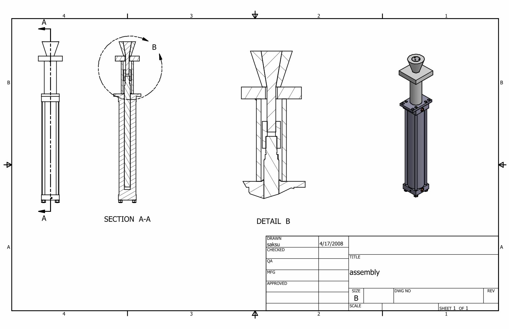
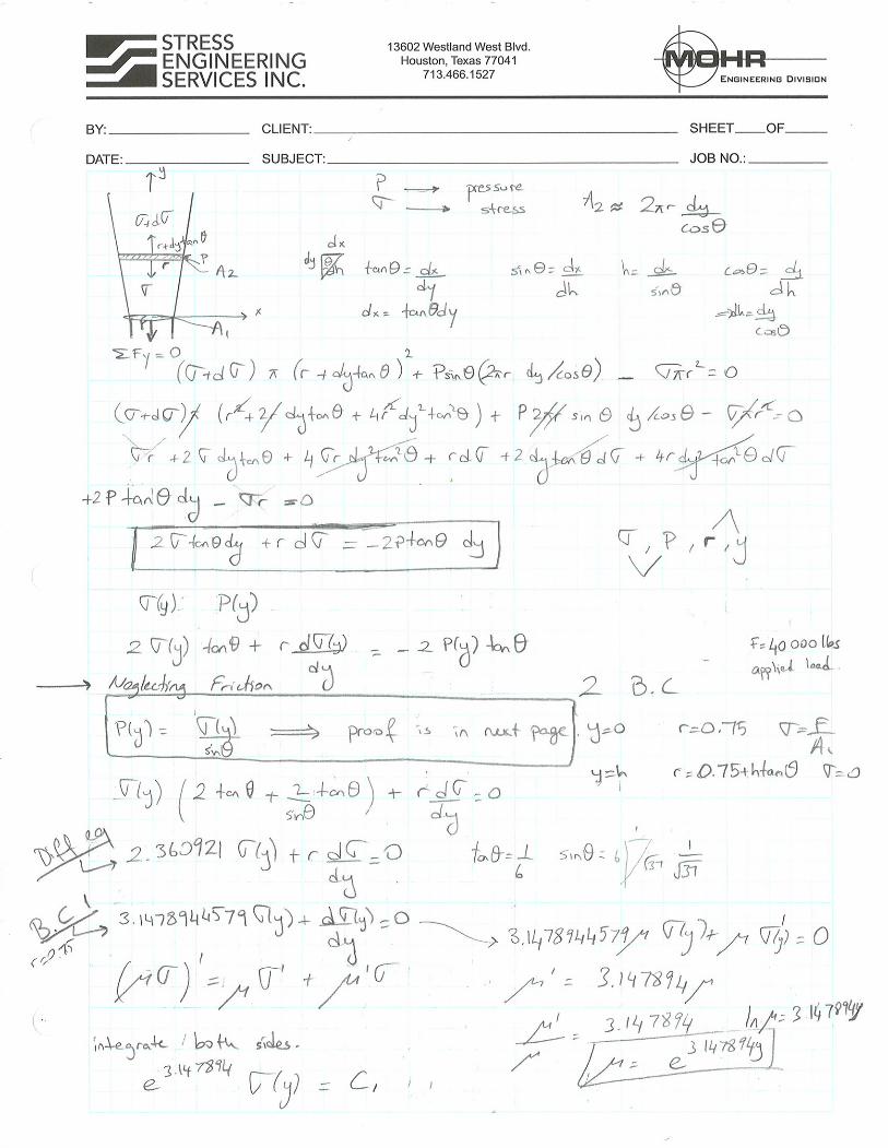
1.0 INTRODUCTION API has contracted Mohr Engineering division of Stress Engineering Services, Inc. to establish a measurement of friction constant for drilling slips. For this purpose a new experiment that mimics the actual slip to bowl area is performed as described later. 1.1 Background drill pipe failures in the slip area Failures of drill pipes in the slip area are caused by several factors. Friction constant at that area is also a major parameter that affects the stresses, thus failures, of drill pipes at the slips [1]. Therefore using a correct value of friction constant in these calculations is of fundamental importance. 1.2 Basics of Friction When there is contact between two surfaces, a force is required to initiate and maintain relative motion of these surfaces. Laws of sliding friction state that this force is called the friction force and it always acts in the opposite direction of the relative displacement. It is independent of the nominal area of contact and it is a function of the normal contact force. However, when friction is studied more deeply, it is observed that friction results from complex interactions between contacting bodies. These interactions include the effects of surface asperity deformation, plastic gross deformation of a weaker material by hard surface asperities or wear particles and molecular interaction leading to adhesion at the points of intimate contact. The relative importance of these parameters is determined by mechanical and physico-chemical properties of the materials in contact, surface topography and environment [2 and the references cited therein]. The friction of solids is controlled by three major phenomena: the real area of contact, shear strength of the adhesive junctions formed at the points of real contact and the way these junctions are ruptured. Since the surfaces in contact are covered with asperities having random height distribution, the deformation where the contact takes place is not fully elastic [2]. The important components of friction are: friction due to adhesion, friction due to ploughing and friction due to deformation [2]. Even though, the formulas estimating the coefficient of friction for these components are highly nonlinear [2, 3], we will try to estimate a mean friction constant for the slips with the designed experiment. This is akin to Coulomb friction we as engineers are all familiar with and will enable the equation to simplify to F = µN. 1.3 Experimental Design The test has 4 components: hydraulic cylinder, specimen mandrel (slips), support stand (pipe) and a conical female mate to the mandrel (bowl) (See Fig1). Relative motion between the mandrel and the conical female mate is established by pulling the mandrel down through the cone by the hydraulic cylinder.

Figure 1 Experimental Set up
As illustrated in Figure 2, three small openings are machined into the specimen mandrel and rectangular strain gage rosettes are attached to these grooves. These strain gages are intended to capture the deformation at the contact surface. The principal strain direction is assumed to be collinear with the friction angle, and thus, directly provide a single value for the coefficient of friction. Note that the female mating bowl was designed to have constant hoop strain for the same contact pressure over its entire length. The testing reality of this was that the resulting contact stress measured to be constant throughout the contact area.
Figure 2 Strain gages attached to the specimen mandrel.
In addition, another set (total of 6 locations) of biaxial strain gages are attached to various locations of the female cone. These readings are used to calculate the pressure at the cone to mandrel interface using the thick wall pressure vessel theory.
Also, the pressure distribution along the contact surfaces is measured via a commercially available pressure sensor –Pressurex [4]. The sensor is a mylar based film that contains a layer of tiny microcapsules. When force is applied upon the film, it causes the microcapsules to rupture, producing an instantaneous and permanent high resolution "topographical" image of pressure variation across the contact area. This technique is used to measure the pressure at the contact surface during the test. 2.0 SUMMARY OF TESTING 2.1 Test Objective The objective of the test is to mimic the actual drill pipe slip operation to identify the effective friction constant between the surfaces. 2.2 Major Work Elements The elements that need to be addressed are:
• Pressure distribution at the contact surface must be analyzed and measured. This pressure distribution plays a key role in identifying the failure mode of the drill pipes.
• The strain gage readings must be utilized to estimate the effective friction constant of the surfaces.
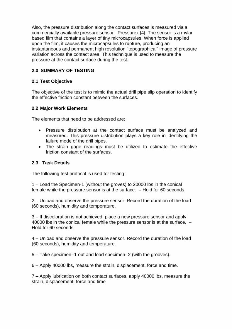
2.3 Task Details The following test protocol is used for testing: 1 – Load the Specimen-1 (without the groves) to 20000 lbs in the conical female while the pressure sensor is at the surface. – Hold for 60 seconds 2 – Unload and observe the pressure sensor. Record the duration of the load (60 seconds), humidity and temperature. 3 – If discoloration is not achieved, place a new pressure sensor and apply 40000 lbs in the conical female while the pressure sensor is at the surface. – Hold for 60 seconds 4 – Unload and observe the pressure sensor. Record the duration of the load (60 seconds), humidity and temperature. 5 – Take specimen- 1 out and load specimen- 2 (with the grooves). 6 – Apply 40000 lbs, measure the strain, displacement, force and time. 7 – Apply lubrication on both contact surfaces, apply 40000 lbs, measure the strain, displacement, force and time

3.0 TEST RESULTS AND CONCLUSIONS The strain gage data is analysed for the solid mandrel and the principal strain directions are extracted. It is well established in the Coulomb friction theory that the tangent of the friction angle is actually the friction constant or coefficient of friction. Our goal was to devise a relatively simple and direct measurement of the coefficient of friction and this appears to be a simple and direct way to achieve that goal. The principal strain directions at the strain gage locations vary both in time/load and with location. However, the main problem arises from the fact that the tangent of the principal strain direction changes sign and becomes negative during part of the test. A negative friction constant does not have any physical meaning. The reasons for the sign change / negative friction constant are investigated and following conclusion is made: the size of the strain gages are not small enough to capture the displacements occurring at the contact surface, where the actual effect of friction is impacting the mandrel. Therefore this test can not be used for the purpose. The solution of the problem is analysed using fundamental elasticity equations (Appendix B). The solution neglected the friction force at the contact surface and the pressure distribution calculated to be highly nonlinear. To verify the results, pressure sensors are used and the test is performed. In practice, due to the expansion of the female cone, the pressure distribution along the cone is constant (Appendix C). This constant pressure is used to approximate the female cone as a pressure vessel. Strain data measured at the outside of the cone is used to estimate the force equilibrium of the female cone. It didn’t take long to realize that, we needed many more data points to reach the resolution we needed which is very costly and requires tedious calculations. In addition, due to the imperfections of the contact geometry, the pressure was not consistent – was not perfectly axis-symmetric in the cone. This error propagated and contributed to the difference at the measured vs. calculated strain values. Using the pressure vessel assumption led to poor results and could not be used to quantify the friction constant at the contact area. These deficiencies make it impractical to use either of these methods to create a simple inexpensive method to measure a coefficient of friction using these fixtures. It is therefore recommended that the coefficient of friction be established using the test method and fixtures developed by the API 7A1 committee. These particular test pieces need to be made specifically for this application versus the typical with the dominant machine marks approximately perpendicular to the tangent direction. This is done to simulate the lathe cutting marks on the slips and bowl and the relative motion perpendicular to those machine marks. Testing with these conditions will be investigated and report back after establishing the cost to make these special parts and run some comparative tests.

References: 1 – Reinhold, W. B. and Spiri W. H. “Why does drill pipe fail in the slip area?” World Oil October 1959. 2 – T. A. Stolarski “Tribology in Machine Design” Butterworth-Heinemann 3 – H. Olsson, K.J. Astrom, C. Canudas de Wit, M. Gafvert, P. Lischinsky “Friction Models and Friction Compensation” 4 – http://www.pressurex.com/

Appendix A
SECTION A-A
DETAIL B
1
1
2
2
3
3
4
4
A A
B B
SHEET 1 OF 1
DRAWN
CHECKED
QA
MFG
APPROVED
saksu 4/17/2008
DWG NO
TITLE
assembly
SIZE
BSCALE
REV
A
A
B

SECTION A-A
1
1
2
2
3
3
4
4
A A
B B
SHEET 1 OF 1
DRAWN
CHECKED
QA
MFG
APPROVED
saksu 4/17/2008
DWG NO
welded_parts
TITLE
SIZE
BSCALE
REV
A
A
2.0
13.75
3.5
5
n2.0
10
10
Tac weld on both sides

1
1
2
2
3
3
4
4
A A
B B
SHEET 1 OF 1
DRAWN
CHECKED
QA
MFG
APPROVED
saksu 4/17/2008
DWG NO
TITLE
bushing -- 4130/4140 100-115ksi
SIZE
BSCALE
REV
n3.00
4.50
1.75 2.00
1 1/2-12 UNF - 2B
1 7/8-12 UN - 2B
SECTION A-A
1
1
2
2
3
3
4
4
A A
B B
SHEET 1 OF 1
DRAWN
CHECKED
QA
MFG
APPROVED
saksu 3/27/2008
DWG NO
TITLE
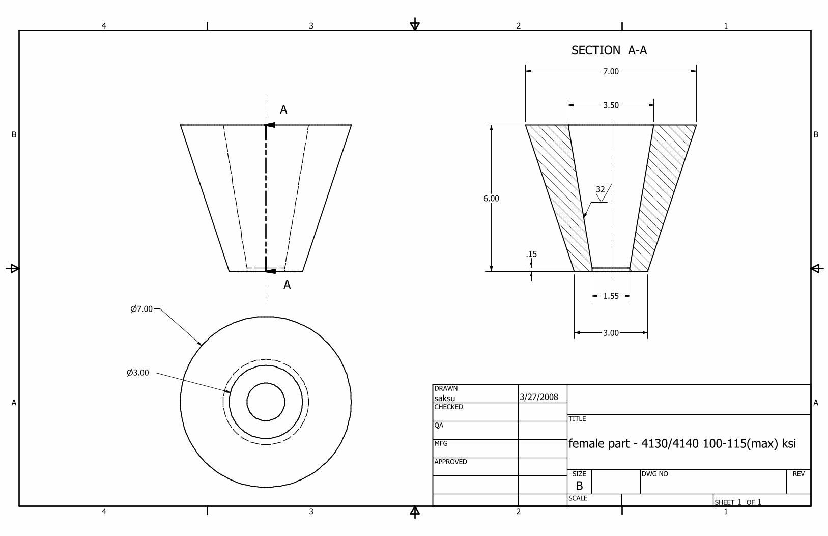
female part - 4130/4140 100-115(max) ksi
SIZE
BSCALE
REV
A
A
6.00
3.00
3.50
7.00
32
n7.00
n3.00
1.55
.15

1
1
2
2
3
3
4
4
A A
B B
SHEET 1 OF 1
DRAWN
CHECKED
QA
MFG
APPROVED
saksu 4/18/2008
DWG NO
pipe
TITLE
pipe -- steel 50 ksi or better
SIZE
BSCALE
REV
13.75
3.5 5.0
any available pipe Ø 3.5 min ID1/2 min wall thicknessØ 8 5/8 max OD

1
1
2
2
3
3
4
4
A A
B B
SHEET 1 OF 1
DRAWN
CHECKED
QA
MFG
APPROVED
saksu 4/18/2008
DWG NO
small_plate
TITLE
small plate -- steel 50 ksi
SIZE
BSCALE
REV
10
2.0
Flame Cut perimeter acceptable
10
10
n2.0

SECTION C-C
SECTION B-B
SECTION A-A
1
1
2
2
3
3
4
4
A A
B B
SHEET 1 OF 1
DRAWN
CHECKED
QA
MFG
APPROVED
saksu 4/17/2008
DWG NO
specimen
TITLE
specimen -- 4130/4140 125(min) ksi
SIZE
BSCALE
Mohr Engineering
REV
1
C
CB
B
A
A
120°
1.00
3.00
5.00
120°
1.00
1.15
.92
1.25
1.58
R.50
.82
n.38 x3
.04 X 45° Chamfer
1.50
7.50 6.00
.99
.65
1.32
120°
120°
120°

1
1
2
2
3
3
4
4
A A
B B
SHEET 1 OF 1
DRAWN
CHECKED
QA
MFG
APPROVED
saksu 4/18/2008
DWG NO
specimen_2
TITLE
specimen2 -- 4130/4140 125(min) ksi
SIZE
BSCALE
REV
n3.50
1 1/2-12 UNF - 2A
.04 X 45° Chamfer
13.50
6.00
6.00
1.50
32
n1.50

Appendix B


Appendix C
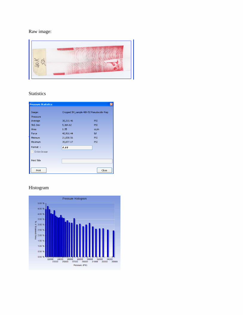
Raw image:
Statistics
Histogram

Line Scan
Pseudocolor Rep

Appendix D

Mohr Engineering Division PN172630
Friction constant Investigation ofAPI Drilling Tools
by Saltuk B. Aksu, Ph.D
Reference Material:Boresi A., Schmidth R., Advanced Mechanics of Materials. Sixth Edition John Wiley &
Sons, Inc.
Timoshenko and Goodier, Theory of Elasticity, Second Edition McGraw-Hill, Inc.
Material Properties:Material: 4340 Sy4340 1250003 psi⋅:= Su4340 190000psi:= E4340 29000000 psi⋅:= υ .29:=
1 of 7 11/3/2008

Mohr Engineering Division PN172630
Pressure Vessel Assumption of the cone:
Input Values 10
Pi 35000 psi⋅:= Internal pressure
Po 0 psi⋅:= External pressure
D 23.3291 in⋅
21.6688 in⋅+
6.667 in=:= Outside diameter of vessel
d 3.3291 in⋅:= Inside diameter of vessel
dp 0 in⋅:= Pipe diameter (worst case; minimum size pipe)
E 29 106
⋅ psi⋅:= Modulus of elasticity
Sy 125 ksi⋅:= Material yield strength
Su 190 ksi⋅:= Material ultimate strength
Calculations
N 1000:= j 0 N..:= Number of increments through
the cylinder wall for stress
distribution through the wall
ad
2:=
inner radius
bD
23.333 in=:=
outer radius
rj
j
Nb a−( )⋅ a+:=
variable
Calculate the tangential (hoop) stress through the cylinder wall
σtj
Pi
d2rj( )2 b
2+
⋅
rj( )2 b
2d2
−( )⋅
⋅:=
σt0
6.864 107
× psi= Stress at ID
σtN
2
3.807 107
× psi=Stress at mid-wall
2 of 7 11/3/2008

Mohr Engineering Division PN172630
σtN
2.74 107
× psi= Stress at OD
YD
d:= Ratio of diameters
Zj
D
dj
ND d−( )⋅+
:=Ratio of diameters incremented
through the cylinder wall
Calculate the radial stress through the cylinder wall
σrj
Pi
d2rj( )2 b
2−
⋅
rj( )2 b
2d2
−( )⋅
⋅:=
Stress at IDσr0
4− 107
× psi⋅=
Stress at mid-wallσrN
2
1− 107
× psi⋅=
Stress at ODσrN
0 psi⋅=
σa 0:=
3 4 5 6 75− 10
4×
0
5 104
×
1 105
×
σrj
ksi
σtj
ksi
D
Zj
in
3 of 7 11/3/2008

Mohr Engineering Division PN172630
σVMj
.5 σtj
σrj
−
2
σtj
σa−
2
+ σa σrj
−
2
+
⋅:=
3 4 5 6 72 10
4×
4 104
×
6 104
×
8 104
×
1 105
×
σVMj
ksi
D
Zj
in
εrj
1
Eσrj
υ σtj
⋅−
⋅:= εrN
0.274−=
εtj
1
Eσtj
υ σrj
⋅−
⋅:= εtN
0.945=
Input Values 11
D11 22.9872 in⋅
21.5064 in⋅+
6 in=:= Outside diameter of vessel
d11 2.9872 in⋅:= Inside diameter of vessel
Calculations
a11d11
21.494 in=:=
inner radius
b11D11
23 in=:=
outer radius
4 of 7 11/3/2008

Mohr Engineering Division PN172630
r11j
j
Nb a−( )⋅ a+:=
variable
Calculate the tangential (hoop) stress through the cylinder wall
σt11j
Pi
d11( )2r11j( )2 b11
2+
⋅
r11j( )2 b112 d11
2−( )⋅
⋅:=
σt110
1.731 107
× psi= Stress at ID
σt11N
2
9.949 106
× psi=Stress at mid-wall
σt11N
7.376 106
× psi= Stress at OD
YD
d:= Ratio of diameters
Zj
D
dj
ND d−( )⋅+
:=Ratio of diameters incremented
through the cylinder wall
Calculate the radial stress through the cylinder wall
σr11j
Pi
d112r11j( )2 b11
2−
⋅
r11j( )2 b11
2d11
2−( )⋅
⋅:=
Stress at IDσr11
09− 10
6× psi⋅=
Stress at mid-wallσr11N
2
2− 106
× psi⋅=
Stress at ODσr11
N774346 psi⋅=
σa11 0:=
5 of 7 11/3/2008

Mohr Engineering Division PN172630
3 4 5 6 71− 10
4×
0
1 104
×
2 104
×
σr11j
ksi
σt11j
ksi
D
Zj
in
σVM11j
.5 σt11j
σr11j
−
2
σt11j
σa11−
2
+ σa11 σr11j
−
2
+
⋅:=
3 4 5 6 75 10
3×
1 104
×
1.5 104
×
2 104
×
2.5 104
×
σVM11j
ksi
D
Zj
in
εr11j
1
Eσr11
jυ σt11
j
⋅−
⋅:= εr11N
0.047−=
6 of 7 11/3/2008

Mohr Engineering Division PN172630
εt11j
1
Eσt11
jυ σr11
j
⋅−
⋅:= εt11N
0.247=
7 of 7 11/3/2008

Appendix E


Petroleum and natural gas industries — Drilling and well-servicing equipment
1 Scope
This International Standard provides general principles and specifies requirements for design, manufacture and testing of new drilling and well-servicing equipment and of replacement primary load-carrying components manufactured subsequent to the publication of this International Standard.
This International Standard is applicable to the following equipment:
a) rotary tables;
b) rotary bushings
c) API rotary slips designed for use in tapered slip bowls drilling bowls with a 4 inch per foot API taper;
d) Non-API rotary slips designed for use in tapered slipdrilling bowls with any taper other than a 4 inch per foot API taper;
e) rotary hoses;
f) piston mud-pump components;
g) drawworks components;
h) Manual spiders that use API rotary slips as in 1 c) above not capable of use as elevators, that are installed on or above the master bushing/rotary table;
i) Manual spiders that use rotary slips not having a taper of 4” per ft ( 33.333 cm per m ) not capable of use as elevators, that are installed on or above the master bushing/rotary table;
j) Rotary slips not having a taper of 4” per ft ( 33.333 cm per m ) for use in manual spiders as in 1 h) above ;
k) Spring, pneumatic or hydraulic spiders with integral slips not capable of use as elevators, that are installed on or above the master bushing/rotary table;
l) Spring, pneumatic or hydraulic spiders with integral slips not capable of use as elevators, that are installed in or partly in the rotary table;
m) manual tongs;
n) safety clamps not used as hoisting devices;
o) power tongs, including spinning wrenches;
p) Drilling tapered slip bowls
q) Rotary slip systems include rotary slips of all tapers and types not capable of being used as elevators, and all drilling bowls, rotary slip frames, rotary bushings / adapters, and master bushings needed to fit into the rotary table for the purpose of suspending tubular goods from the rotary table;
Annex A gives a number of standardized supplementary requirements which apply only when specified.
The above entries in red font are proposed to be replaced with the following:
Attachment B

INTERNATIONAL STANDARD ISO 14693:2003(E)
Rotary slips not capable of being used as elevators that have dies installed on the internal diameter to grip the outer diameter surface of the pipe body of various tubular goods, and a tapered outside diameter to fit inside drilling bowls that are operated manually or by spring (s) and / or pneumatic or hydraulic power that are installed above, on, in, or partly in the master bushing for the purpose of suspending tubular goods of any type from the rotary table
2 Normative references
The following referenced documents are indispensable for the application of this document. For dated references, only the edition cited applies. For undated references, the latest edition of the referenced document (including any amendments) applies.
ISO 148, Steel — Charpy impact test (V-notch)
ISO 6892, Metallic materials — Tensile testing at ambient temperature
ISO 7500-1, Metallic materials — Verification of static uniaxial testing machines — Part 1: Tension/compression testing machines — Verification and calibration of the force-measuring system
API Spec 5B, Specification for threading, gaging and thread inspection of casing, tubing, and line pipe threads
ANSI/AGMA1) 2004-B89, Gear Materials and Heat Treatment Manual
ANSI2)/ASME3) B1.1, Unified Inch Screw Threads (UN and UNR Thread Form)
ANSI/ASME B1.2, Gages and Gaging for Unified Inch Screw Threads
ANSI/AWS4) D1.1, Structural Welding Code — Steel
ASME Boiler and Pressure Vessel Code Section V, Nondestructive Examination
ASME Boiler and Pressure Vessel Code Section VIII, Alternative Rules for Construction of High Pressure Vessels
ASME Boiler and Pressure Vessel Code Section IX, Welding and Brazing Qualifications
ASNT5) TC-1A, Recommended Practice for Personnel Qualification and Certification in Nondestructive Testing
ASTM6) A 370, Standard Test Methods and Definitions for Mechanical Testing of Steel Products
ASTM A 388, Standard Practice for Ultrasonic Examination of Heavy Steel Forgings
ASTM A 751, Standard Test Methods, Practices, and Terminology for Chemical Analysis of Steel Products
ASTM A 770, Standard Specification for Through-Thickness Tension Testing of Steel Plates for Special Applications
ASTM E 4, Standard Practices for Force Verification of Testing Machines
ASTM E 125, Standard Reference Photographs for Magnetic Particle Indications on Ferrous Castings
1) American Gear Manufacturers Association, 1500 King Street, Suite 201, Alexandria, VA 22314, USA.
2) American National Standards Institute, 1430 Broadway, New York, NY 10018, USA
3) American Society of Mechanical Engineers, 345 East 47th Street, New York, NY 10017, USA.
4) American Welding Society, 550 N.W. LeJeune Road, Box 351040, Miami, FL 33135, USA.
5) American Society for Nondestructive Testing, 4153 Arlingate Plaza, Box 28518, Columbus, OH 43228, USA.
6) American Society for Testing and Materials, 100 Barr Harbor Drive, West Conshohocken, PA 19428, USA.

3.1.20 special process operation that may change or affect the mechanical properties, including toughness, of the materials used in the equipment
3.1.21 test unit prototype unit upon which a design verification test is conducted
3.2 Abbreviated terms
HAZ heat-affected zone
NDE non-destructive examination
PWHT post-weld heat treatment
TIR total indicated runout
4 Design
4.1 Design conditions
Drilling equipment shall be designed, manufactured and tested such that it is in every respect fit for its intended purpose. The equipment shall safely transfer the load for which it is intended. The equipment shall be designed for safe operation.
The following design conditions shall apply:
? the design load and the safe working load are defined as in Clause 3. The operator of the equipment shall be responsible for the determination of the safe working load for specific operations;
? unless changed by a supplementary requirement (see Annex A, SR2 and SR2A), the design and minimum operating temperature for rotary tables, rotary slips, drilling bowls, rotary bushings, rotary adapters, and rotary slip systems, power tongs and drawworks is 0 °C (32 °F). The design and minimum operating temperature for safety clamps, spiders and manual tongs is ? 20 °C (? 4 °F), unless changed by a supplementary requirement.
CAUTION — Use of equipment covered by this International Standard at rated loads and temperatures below the design temperatures noted above is not recommended unless appropriate materials with the required toughness properties at lower design temperatures have been used in the manufacture of the equipment (see Annex A, SR2 and SR2A).
4.2 Strength analysis
4.2.1 General
The equipment design analysis shall address excessive yielding, fatigue or buckling as possible modes of failure.
The strength analysis shall be based on the elastic theory. Alternatively, ultimate strength (plastic) analysis may be used where justified by design documentation.
All forces that may govern the design shall be taken into account. For each cross-section to be considered, the most unfavorable combination, position, and direction of forces shall be used.
4.2.2 Simplified assumptions
Simplified assumptions regarding stress distribution and stress concentration may be used, provided that assumptions are made in accordance with generally accepted practice or based on sufficiently comprehensive experience or tests.

4.3 Size class designation
The size class designation for equipment shall represent dimensional interchangeability in accordance with Clause 9.
4.4 Rating
4.4.1 Rotary tables, spiders, rotary slips, drilling bowls/slip frames, rotary bushings (other than Kelly bushings), rotary adapters, master bushings, manual and power tongs furnished under this International Standard shall be rated in accordance with the requirements specified herein.
4.4.2 The static ratings for all bearings within the primary load path shall meet or exceed the rated load for the equipment.
4.4.3 Power and manual tongs shall be assigned torque ratings by the manufacturer for all configurations for which the tong is designed.
4.5 Load rating basis
The load rating shall be based on:
the design safety factor as specified in 4.6 unless specified otherwise in section 9;
the minimum specified yield strength of the material used in the primary load-carrying components;
the stress distribution as determined by design calculations and/or data developed in a design verification load test as specified in 5.6.
4.6 Design safety factor
4.6.1 Design safety factor for spiders and, rotary slips, drilling bowls, and rotary bushings shall be established as follows[MSOffice1]:
Load rating R
Design safety factor FDS
? 1 334 kN (150 short tons) 3,00
1 334 kN to 4 448 kN (150 short tons to 500 short tons) inclusive 3,00 – 0,75(R – 1 334)/3 114a 3,00 – 0,75(R – 150)/350b
? 4 448 kN (500 short tons) 2,25
a In this formula, the value of R shall be expressed in SI units of kilonewtons. b In this formula, the value of R shall be expressed in USC units of short tons.
The design safety factor is intended as a design criterion and shall not under any circumstances be construed as allowing loads on the equipment in excess of the rated load.
4.6.2 The minimum design safety factor of structural components in the primary load path of rotary tables, tapered slip bowls, and rotary bushings shall be 1,67.
Note: Bob’s wording to be added

Key 1 centreline of first row of teeth (Figure 7) a See Figure 7 and 9.2.6.
Figure 6 — Rotary table pinion-straight shaft extension (see Table 3 for dimensions)
9.2.6 Drive sprocket
The distance, L, between the centre of the rotary table and the centre of the first row of sprocket teeth (see Figure 7) shall be 1 353 mm (53 1/4 in) for machines that will pass a 510 mm (20 in) bit or larger, and shall be 1 118 mm (44 in) for machines that will not pass a 510 mm (20 in) bit, except that, by agreement between the manufacturer and purchaser, the distance of 1 353 mm (53 1/4 in) may be used on machines that will not pass a 510 mm (20 in) bit. The distance, L, shall be either 1 353 mm or 1 651 mm (53 1/4 in or 65 in) for the 1 257 mm (49 1/2 in) nominal rotary table. The distance, L, shall be 1 840 mm (72 in) for the 60 1/2 in nominal rotary table. These distances may be stamped on the name plate (if used) attached to the rotary table.
9.2.7 Rotary table openings
Rotary tables for use with square-drive master bushings shall conform to the requirements of Table 4 and Figure 8. Rotary tables for use with the four-pin-drive master bushings shall conform to the requirements in Table 5 and Figure 9. This subclause does not preclude rotary tables of other nominal sizes.
9.2.8 Demountable rotary table sprockets
Demountable rotary table sprockets are shown in Table 6 and Figure 10. The sprockets, both single-strand and double-strand, have a common bolt circle.
9.3 Rotary bushings
9.3.1 General
Rotary bushings shall include kelly bushings, master bushings, and bushing adapters as defined below. API rotary bushings are specified for the purpose of dimensional interchangeability, but non-API rotary bushings shall also be included for the purpose of ensuring compliance with the requirements specified below.
9.3.2 Kelly bushings
API square-drive kelly bushing dimensions shall comply with those shown in Figure 7.
API four-pin-drive kelly bushing dimensions shall comply with those shown in Figure 9 and Table 5.
9.3.3 Master bushing and Bushing Adapters
9.3.3.1 The dimensions of API square-drive master bushings and API rotary table square-drive master bushings shall conform to the requirements of Table 4 and Figure 8. Dimensions for API four-pin-drive master bushings shall conform to the requirements in Table 5 and Figure 9. Master bushings that have dimensions that do not

INTERNATIONAL STANDARD ISO 14693:2003(E)
comply with those shown in Table 4 or Table 5 shall be regarded as non-API master bushings. Master bushings are used to fit inside rotary tables or bushing adapters as applicable to provide a means by which to transfer loads from the rotary slips to the rotary table that are created when a drill string is suspended by the rotary table with rotary slips. All master bushing dimensions, tolerances, and materials of construction (including both API and non-API master bushings) shall be such that when new rotary slips are fitted into new drilling bowls, which are fitted into new master bushings that are fitted into either bushing adapters or the rotary table opening, the highest rated rotary slips that can be used will suspend a drillstring load that is twice the load rating of the rotary slips from the rotary table without exceeding 90% of the minimum yield strength of the material of the most highly stressed components of the rotary slips, drilling bowls, master bushing, and bushing adapters (if fitted).
9.3.3.2 The requirements of __, __, and __ shall not apply to API master bushings[MSOffice2].
9.3.3.3 The requirements of __, __, and __ shall not apply to non-API master bushings.
9.3.3.4 The requirements of sections 4.6, 8.4.7.4.1, and 8.4.7.4.2 shall apply to both API and non-API master bushings.
9.3.3.5 Marking
Both API and non-API Master bushings covered by this standard shall be marked with the manufacturer's name or mark and the load rating, along with a unique serial number that shall provide traceability in accordance with requirements specified in section 8.4.5.[MSOffice3]
9.3.4 Bushing adapters
9.3.4.1 Bushing adapters are used in rotary table openings to allow smaller-size master bushings to be installed. Bushing adapter dimensions and tolerances shall be such that when new rotary slips are fitted into new drilling bowls, the rotary slips will suspend a drillstring that weighs twice the load rating of the rotary slips from the rotary table without exceeding 90% of the minimum yield strength of the material of the most highly stressed components of the rotary bushing assembly, with shall include, but is not limited to API and non-API drilling bowls, bushing adapters and master bushings. API bushing adapters are those that comply with the dimensions and tolerances that allow them to be fitted into new rotary table openings with tolerances that do not exceed maximum or minimum values. The inside diameter (s) dimensions of API bushing adapters shall also allow the fitting of new API master bushings within documented clearances. Non-API bushing adapters shall fit into new API rotary tables, and allow non-API master bushings that are intended to be used with such bushing adapters without exceeding documented clearances.
9.3.4.2 The load ratings and design safety factors specified in section 4.6 shall apply to both API and non-API bushing adapters. The requirements of section 8.4.7.4.1 and 8.4.7.4.2 shall apply to both API and non-API adapter bushings.
9.3.4.3 The requirements of __, __, and __ shall not apply to API bushing adapters.
9.3.4.4 The requirements of __, __, and __ shall not apply to non-API adapter bushings.
9.3.4.5 Marking
Both API and non-API adapter bushings covered by this standard shall be marked with the manufacturer's name or mark and the load rating, along with a unique serial number that shall provide traceability in accordance with requirements specified in section 8.4.5.
9.4 Drilling Tapered Slip Bowls
9.4.1 Tapered Slip Drilling bowls are used between rotary slips and master bushings to provide a means by which to transfer loads from the rotary slips to the master bushing that are created when drillstrings are suspended from the rotary table with rotary slips. API Drilling bowls are utilized with API rotary slips which incorporate a taper of 333,33 mm/m (4 in/ft) on the inner diameter of the drilling bowl, and have suitable length dimensions to allow new API rotary slips to fit in accordance with the manufacturer’s dimensions and tolerances
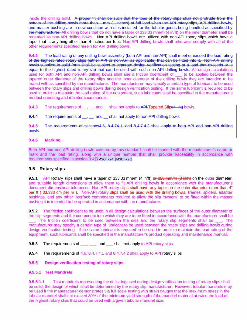
inside the drilling bowl. A proper fit shall be such that the toes of the rotary slips shall not protrude from the bottom of the drilling bowls more than _ mm (_ inches) at full load when the API rotary slips, API drilling bowls, and master bushing are in new condition with dies installed for the tubular goods being handled as specified by the manufacturer. All drilling bowls that do not have a taper of 333,33 mm/m (4 in/ft) on the inner diameter shall be regarded as non-API drilling bowls. Non-API drilling bowls are utilized with non-API rotary slips which have a taper that is anything other than 4 inches per foot. Non-API drilling bowls shall otherwise comply with all of the other requirements specified herein for API drilling bowls.
9.4.2 The load rating of any drilling bowl assembly (both API and non-API) shall meet or exceed the load rating of the highest rated rotary slips (either API or non-API as applicable) that can be fitted into it. Non-API drilling bowls supplied in solid form shall be subject to separate design verification testing at a load that exceeds or is equal to the highest rated rotary slip that can be used with such non-API drilling bowls. All design calculations used for both API and non-API drilling bowls shall use a friction coefficient of ___ to be applied between the tapered outer diameter of the rotary slips and the inner diameter of the drilling bowls they are intended to be mated with as specified by the manufacturer. The manufacturer may specify a certain type of lubricant to be used between the rotary slips and drilling bowls during design verification testing. If the same lubricant is required to be used in order to maintain the load rating of the equipment, such lubricants shall be specified in the manufacturer’s product operating and maintenance manual.
9.4.3 The requirements of __, __, and __ shall not apply to API Tapered Slipdrilling bowls.
9.4.4 The requirements of __, __, and __ shall not apply to non-API drilling bowls.
9.4.5 The requirements of sections4.6, 8.4.74.1, and 8.4.7.4.2 shall apply to both API and non-API drilling bowls.
9.4.6 Marking
Both API and non-API drilling bowls covered by this standard shall be marked with the manufacturer's name or mark and the load rating, along with a unique number that shall provide traceability in accordance with requirements specified in section 8.4.5[MSOffice4].[MSOffice5]
9.5 Rotary slips
9.5.1 API Rotary slips shall have a taper of 333,33 mm/m (4 in/ft) or 250 mm/m (3 in/ft) on the outer diameter, and suitable length dimensions to allow them to fit API drilling bowls in accordance with the manufacturer’s document dimensional tolerances. Non-API rotary slips shall have any taper on the outer diameter other than 4” per ft ( 33.333 cm per m ). Non-API rotary slips shall be used with the drilling bowls, frames, spiders, adapter bushings, and any other interface components required to allow the slip “system” to be fitted within the master bushing it is intended to be operated in accordance with the manufacturer.
9.5.2 The friction coefficient to be used in all design calculations between the surfaces of the outer diameter of the slip segments and the component into which they are to be fitted in accordance with the manufacturer shall be ___. The friction coefficient to be used between the dies and the rotary slip segments shall be ___. The manufacturer may specify a certain type of lubricant to be used between the rotary slips and drilling bowls during design verification testing. If the same lubricant is required to be used in order to maintain the load rating of the equipment, such lubricants shall be specified in the manufacturer’s product operating and maintenance manual.
9.5.3 The requirements of ___, ___, and ___ shall not apply to API rotary slips.
9.5.4 The requirements of 4.6, 8.4.7.4.1 and 8.4.7.4.2 shall apply to API rotary slips
9.5.5 Design verification testing of rotary slips
9.5.5.1 Test Mandrels
9.5.5.1.1 Test mandrels representing the drillstring used during design verification testing of rotary slips shall be solid; the design of which shall be determined by the rotary slip manufacturer. However, tubular mandrels may be used if the manufacturer demonstrates via full scale testing with strain gauges that the maximum stress in the tubular mandrel shall not exceed 80% of the minimum yield strength of the mandrel material at twice the load of the highest rotary slips that could be used with a given tubular mandrel size.

INTERNATIONAL STANDARD ISO 14693:2003(E)
9.5.5.1.2 A “Fit for Purpose” test shall also be performed with a tubular mandrel at a load that meets or exceeds the slip crushing load as calculated by the formula below.
R-S2
1
12 2
z y z
s s
F ADK DK
L L
s=æ ö÷ç+ + ÷ç ÷è ø
(E ??)
Where,
R-SzF = Reinhold-Spiri prediction for axial force at which yielding initiates on inner diameter of drill pipe [lbs]
ys = Yield stress of tubular mandrel material [psi]
zA = Cross-sectional area of tubular mandrel [square inches]
D = Outside diameter of tubular mandrel [inches]
sL = Length of slip contact with tubular mandrel [inches]
K = Transverse load factor or “K factor”.
The transverse load factor K is given by the following equation:
1 tan
tanK m a
m a-=
+ (E ??)
Where,
m = Coefficient of friction between the slips and the bowl
a = Taper angle of slip bowl. 9.5.6 Design verification test loads For rotary slips rated for 150 tons or less, destructive tests may be carried out to verify the design if such tests component of the rotary slips unfit for further service shall be a minimum of 2.25 times the rated load. For rotary slips rated between 150 and 750 tons, destructive tests may also be carried out to verify the design, as long as the test facility, test apparatus, and test procedures are adequate to ensure personnel safety when testing at the loads required to destroy or otherwise render any primary load carrying component of the rotary slips unfit for further service. However, the load required to destroy the rotary slips shall be a minimum of twice the rated load. For rotary slips with a load rating that is equal to or exceeds 750 tons, two design verification tests shall be carried out: - One shall be performed with a solid mandrel at twice the rated load. - Another test shall be performed with a tubular mandrel at twice the rated load. The outer diameter of the tubular mandrel shall be equal to the largest specified nominal tubular diameter size that the rotary slips are designed to handle. The material properties and wall thickness of the tubular mandrel to be utilized during this test shall be such that the highest stress in the mandrel during testing shall not be less than 90% of the its actual yield strength as predicted by the formula specified in section 9.7.1.2 at twice the rated load of the rotary slips

being tested. This test shall include strain gauging and monitoring the stress in the drilling bowls, master bushings or slip frames, spiders, or whatever other interfaces are required to either absorb or transmit the load to the master bushing in which the particular slip “system” is designed to operate. Such testing shall verify that the maximum stress in each component including the rotary slips themselves shall not exceed 90% of the material yield strength of any component at twice the rated load of the rotary slips being tested. 9.5.6.3 Rotary slip design families For the purpose of establishing a load rating via design verification testing required herein for all rotary slips, as well as other primary load-carrying components that the rotary slips are used with in accordance with the manufacturer, one design verification test may be carried out to qualify a number of different sizes of rotary slips called design families. A rotary slip design family shall consist of slip assemblies (which shall include al primary load carrying components) of varying sizes and/or ratings with an identical design concept where the stress distribution of the primary load is similar, given the same design assumptions. 9.5.7 Proof Load Testing Proof-load testing shall be required for all rotary slips that have a designated load rating of 500 tons or greater. The User may require proof-load testing at his option for rotary slips that have a designated load rating that is less than 500 tons by specifying the requirements in SR1 in the purchase agreement.
9.5.8 Toughness testing
The minimum Charpy ‘V’ Notch Impact value shall be no less than 19 ft.-lbs. with an average value of no less then 25 ft.-lbs. at -20 deg. C. This is notwithstanding any additional requirements available to the purchaser by referencing different values for temperatures below -20 deg. C per SR2 or other temperature and impact values that may be invoked by the purchaser per SR2A.
9.5.9 Critical areas
Critical areas shall be defined by the manufacturer on critical area drawings or maps, and shall include all areas where the stress in the component at the rated load is:
? (0.75) x Sy min.
FDS
where
Sy min = the specified min. yield strength
FDS = the design factor
If critical areas are not identified on critical area drawings or maps, then all surfaces of the component shall be considered critical.
Areas of components in which the stress is compressive, and/or where the stress level is:
= 0,1 Sy min FDS
where
Symin = the specified minimum yield strength of the material
FDS = the design factor
shall be exempt from the acceptance criteria defined in 8.4.7.4.1 and 8.4.7.4.2. The low stress areas thus defined may be identified on the critical area map.
9.5.10 Stress-relief design features
Given the failure history of rotary slips, and the operating environment and dynamic forces this equipment is likely to be exposed to over its useful life-span, the design of rotary slips should incorporate features to minimize stress concentrations that could exceed the maximum allowable values specified herein. Such features may be

INTERNATIONAL STANDARD ISO 14693:2003(E)
implemented to minimize stress concentrations in primary load carrying components caused by abrupt changes in cross-sectional area, or to minimize excessive loads caused by friction coefficients that may be lower than those specified in section 9.5.2 above. For example, “load rings” may be featured on the inner diameter of the slip segments for the purpose of distributing the load that is transferred through the dies to multiple areas of the segments, thereby minimizing the load that would otherwise be applied to the cross-sectional area of the bottom of the segments where field failures have been documented. In addition, design features shall allow for a specified amount of wear to critical areas of the slip segment, as well as the drilling bowls in which they are intended to be operated. Such wear limits shall be published in the equipment operating and maintenance manuals.
9.5.11 User information on rotary slips
Instructions for the use, care, inspection, and maintenance of rotary slips shall be published by the manufacturer in the operations and maintenance manuals, with shall include, but not be limited to the following:
a. The specific markings utilized by the manufacture to comply with the marking requirements herein, including the difference between markings used on equipment made to the requirements herein versus the marks that may exist on any slips that were not made to this standard to allow easy visual differentiation between them
b. Traceability documentation c. Inspection requirements and measurable acceptance and rejection criteria d. Considerations that the User should take into account when determining the safe working load, such as
wear limits, dynamic factors and other factors that may affect the coefficient of friction, which can all affect the load capacity of used rotary slips.
e. For slips that are intended to be installed below the rotary table out of sight by the Driller, instructions shall be provided to allow the Driller to allow him to confirm that slips are engaging properly onto tubulars without having to cease rig floor operations. 9.5.12 Marking of rotary slips
Each rotary slip segment or carrier covered by this standard shall be die-stamped or die-cast with the manufacturer's name or mark and the load rating, along with a unique serial number that shall provide traceability in accordance with requirements specified in section 8.4.5. The same segments or carriers used with a selection of rotary slips that have a different rating, depending on how many segments are used to fit a certain diameter pipe, the load rating that is die-stamped or die-cast into the part shall be of a value that is equal to the load that it shares, as long as the total load rating for a given rotary slip assembly is equal to or less than the sum of the individual load ratings of each segment or carrier used in the assembly.
9.6 Spiders that use either API rotary slips or non-API rotary slips that are operated either manually or otherwise which are not capable of use as elevators, that are installed on, in or above the master bushing/rotary table
9.6.1 General
Spider bodies furnished in conformance with this International Standard shall be marked with the manufacturer's name or mark and the rating.
9.6.2 Marking
All spiders covered by this standard shall be marked with the manufacturer's name or mark and the load rating, along with a unique serial number that shall provide traceability to the item’s manufacturing history in accordance with requirements specified in section 8.4.5.
9.6.3 Impact toughness
The following impact toughness values apply to spider bodies.
Components with a specified minimum yield strength of at least 310 MPa (45 000 psi) shall be made from materials possessing a minimum impact toughness of 33 J (25 ft-lbs) at ? 20 °C (? 4 °F). The specified minimum impact toughness shall be an average of 3 tests, with no individual value less than 26 J (19 ft-lbs).

For components with a specified minimum yield strength of less than 310 MPa (45 000 psi), the ? 20 °C (? 4 °F) minimum impact toughness shall be 27 J (20 ft-lbs) with no individual value less than 20 J (15 ft-lbs).
9.6.4 Design verification test
The design verification load test, as described in Clause 5, shall apply.
9.6.5 Proof load test
Proof load testing, as described in 8.6, shall apply.
API 7K 4th Edition
6 Materials Requirements
6.1 GENERAL
This section describes the various material qualifications, property, and processing requirements for primary load carrying and pressure containing components unless otherwise specified.
6.2 WRITTEN SPECIFICATIONS
All materials used in the manufacture of the primary load bearing components of the equipment covered by this specification shall conform to a written specification that meets or exceeds the design requirements.
6.3 MECHANICAL PROPERTIES
6.3.1 Impact Toughness (metallic components only)
6.3.1.1 Impact testing shall be in accordance with ASTM A370.
6.3.1.2 When it is necessary for subsize impact test pieces to be used, the acceptance criteria shall be multiplied by the appropriate adjustment factor listed in table 1. Subsize test pieces of width less than 5 millimeters are not permitted.
6.3.1.3 For design temperatures below -20˚C supplementary impact toughness requirements may apply. See Appendix B, Supplementary Requirements SR2.
6.3.2 Through Thickness Properties (metallic components only)
Where the design requires through thickness properties, materials shall be tested for reduction of area in the through thickness direction according to ASTM A770. The minimum reduction shall be 25 percent.
6.4 MATERIAL QUALIFICATION
The mechanical tests required by this specification shall be performed on the qualification test coupons representing the heat and heat treatment lot used in the manufacture of the component. For non-metallic components, a batch from the same manufacturing lot, with the same chemistry, shall be considered as a heat. Tests shall be performed in accordance with the requirements of ASTM A370, or equivalent national standards, where possible using material in the final heat treated condition. For the purposes of material qualification testing, stress relief following welding is not considered heat treatment. Material qualification tests may be performed before the stress relieving process provided that the stress relieving temperature is below that which changes the heat treatment condition.
6.4.1 Equivalent rounds (metallic components only)
The size of the qualification test coupon for a part shall be determined using the equivalent round (ER) method. Figure 1 illustrates the basic models for determining the ER of simple solid and hollowed parts. Any of the shapes shown may be used for the qualification test coupon. Figure 2 describes the steps for determining the governing ER for more complex sections.
Attachment C
The ER of a part shall be determined using the actual dimensions of the part in the “as heat treated” condition. The ER of the qualification test coupon shall be equal to or greater than the equivalent round dimensions of the part it qualifies, except that the ER is not required to exceed 5 inches. Figure 3 illustrates the procedure for determining the required dimensions of an ASTM A370 keel block.
6.4.2 Material test coupons
Qualification test coupons may be integral with the components they represent or separate from the components or a sacrificial production part. In all cases test coupons shall be from the same heat as the components that they qualify, given the same working operations, and shall be heat treated with the components.
Test specimens shall be removed from integral or separate qualifications test coupons such that their longitudinal center line axis is wholly within the center core ¼ thickness envelope for a solid test coupon or within ⅛ inch (3 millimeters) of the mid-thickness of the thickest section of a hollow test coupon. The gauge length on a tensile specimen or the notch of an impact specimen shall be at least ¼ thickness from the ends of the test coupon.
Test specimens taken from sacrificial production parts shall be removed from the center core ¼ thickness envelope location of the thickest section of the part.
6.5 MANUFACTURE
The manufacturing processes shall ensure repeatability in producing components that meet all the requirements of this specification.
All wrought materials shall be manufactured using processes that produce a wrought structure throughout the component.
All heat treatment operations shall be performed utilizing equipment qualified in accordance with the requirements specified by the manufacturer or processor. The loading of the material within heat treatment furnaces shall be such that the presence of any one part does not adversely affect the heat treating response of any other part within the heat treatment lot. The temperature and time requirements for heat treatment cycles shall be determined in accordance with the manufacturer’s or processor’s written specification. Actual heat treatment temperatures and time shall be recorded, and heat treatment records shall be traceable to relevant components.
6.6 CHEMICAL COMPOSITION (metallic components only)
The material composition of each heat shall be analyzed for all elements specified in the manufacture’s written material specification.
6.7 NON-METALLIC COMPONENTS
The use of non-metallic materials to manufacture primary load carrying components shall be permitted provided that the materials meet the mechanical properties required for the design.
The mechanical property requirements for all non-metallic materials shall be specified with appropriate limits for properties critical to the function of the equipment. The material properties shall be qualified at a minimum temperature of -4°F (-20°C) unless otherwise specified in section 9, and at a specified maximum temperature corresponding to the maximum recommended operating temperature. Material for which the rate of loading affects the mechanical properties, the qualification tests shall be performed at the most severe rate of loading that may be encountered in service.

For materials that do not exhibit yield strength, the value of the ultimate strength multiplied by 0.80 shall be used as the equivalent yield strength.
The manufacturer shall provide specific procedures for the inspection of all non-metallic materials including frequency, methods, equipment, and acceptance and rejection criteria to the user/owner in an inspection and maintenance manual upon delivery of the equipment under a purchase agreement. These procedures shall also include recommendations for maximum intervals for replacement due to aging and shelf life of replacement components. The manufacturer shall also provide instructions and information regarding the material’s resistance to chemical attack, along with a list of what types of chemicals will affect the serviceability of the equipment or its ability to be used at its designated rated load. In addition, the manufacturer shall provide the minimum and maximum temperatures that the equipment can be used at its designated rated load, plus any other ambient conditions that could adversely affect the ability of the equipment to be operated at its designated rated load.
6.7.1 Aramid fiber cordage with unbonded elastomeric coating loaded in simple tension
The material shall be qualified and controlled for conformance to the manufacturer’s written specification. The material specification shall contain, as a minimum with appropriate limits, the uncoated cordage diameter, the denier of the cordage, the coated cord diameter, the twist density, and the tensile strength. The tensile strength shall be tested in accordance with ASTM D4268 or other international standards.
8 Quality Control
8.4 Quality control for specific equipment and components
8.4.7 Surface NDE
8.4.7.4 Acceptance criteria
8.4.7.3 Non-metallic components
The manufacturer shall have written specifications defining the maximum defect size, orientation, grouping, etc. for each type of defect expected. The defect types considered are to be at a minimum, voids, cuts, cracks, and/or tears.
The methods for detection and measurement of the expected defects are to be specified and proven effective in detecting defects no larger than 75% of the maximum allowable size or severity. All primary load carrying components are to be examined in both critical and non-critical areas.

7K ANNEX F – LOAD LIMITING DESIGN OF MANUAL TONGS F.1.1 Purpose The purpose of this specification is to provide standards for certifying a design as load limiting. A load limiting design is one that in the event of an overload, the primary load will be either prevented from increasing or released in a controlled manner without unlatching and with no fragments expelled. Clauses 4.2.4, 4.2.5, 4.6, 5.4, 5.5, and 5.6 regarding the design and design verification testing of manual tongs does not apply to load limiting tongs designed, qualified, and tested in accordance with this annex.
Load limiting designs may be accomplished by the use of materials, components, or mechanisms to release or limit the primary load in an overload condition. The limiting component shall be an integral part of the tool, impossible to be removed, bypassed, or adjusted in the field.
F.1.2 Equipment covered
This specification covers the design, manufacture and testing of load limiting manual tongs.
F.2 Definitions
For the purpose of this appendix, the following definitions apply:
Average limit load: the numerical average of primary load which causes the limiting component to release the primary load.
Limiting component: a component, material or mechanism which will release the primary load in the event of an overload
Load variance: a measure of how widely values are dispersed from the average value
Secondary load: the minimum load capacity of all components in the tool except for the limiting component.
Secondary component: all components with the exception of the limiting component.
F.3 Design
F.3.1 Average limit load
The average limit load shall be determined by testing the limiting component. A minimum sample size of fifty (50) tests of the same size and type of component shall be used. The primary load to the tool required to cause a limit of the load shall be measured or calculated using the mechanical relationship of the measured load to the primary load. The average limit load shall be documented in terms of the output.
Testing shall be performed at the worst case(s) of temperature and rate of loading that may be encountered in service.
Testing of reduced sized specimens is permitted provided that a minimum of two full size tests are conducted to verify the relationship with the specimens.

F.3.2 Load variance
The load variance of the limit load shall be calculated from the test data used to determine the average limit load. The load variance shall be the greater of the standard deviation (determined from the equation below) or one seventh (1/7) of the average limit load:
2
1
)()1(
1 LLn
Dn
ii∑
=
−−
=
Where L is the load corresponding to each sample in measuring the average limit load, n is the number of
samples and L is the average limit load.
F.3.3 Rated load
The rated load shall be a maximum of two load variations below the average limit load. The rated load is given by the equation:
DLR 2−=
F.3.4 Secondary load
The secondary load shall be a minimum of three load variations above the average limit load. The secondary load is given by the equation:
DLS 3+=
F.3.5 Design of secondary components
All components in the primary load path except the limiting component shall be designed such that the minimum material yield strength is equal to or greater than the stresses created by the secondary load.
F.4 Design verification load test
The test procedure is as follows:
a. An assembled production unit shall be loaded to the maximum rated load. After this load has been released, the unit shall be checked for its intended design functions. The function of all of the equipment’s parts shall not be impaired by this loading.
b. The equipment shall be mounted in a test fixture capable of loading the equipment in a similar manner as found in typical field use. This may include, but is not limited to, the use of springs to simulate the compliance of the expected field loading equipment.
c. Strain gauges shall be applied to the unit at all places where high stresses are anticipated in all secondary components, provided that the configuration of the unit permits such techniques. The use of finite-element analysis, models, brittle lacquer, and so forth, is recommended to confirm the

proper location of the strain gauges. Three- element strain gauges are recommended in critical areas to permit determination of the shear stresses and to eliminate the need for exact orientation of the gauges.
d. The design verification test load shall be applied to the unit at a rate expected in field use or, such that the limiting load shall be obtained in a maximum of ten (10) seconds, whichever is the greater rate of loading.
e. The unit shall be loaded at the rate determined in F.4.b until an indication that the load is being limited. The application of the load is then to be stopped manually and held in position for a minimum of 5 minutes. With the application of the load stopped, the measured load on the test unit may decrease in value indicating a release of stored energy. The test unit shall not unlatch and no components, or portions of components, shall become separated from the test unit assembly. This test shall be video recorded.
f. The peak load and the peak stresses computed from the strain gauges shall be recorded. The peak stresses computed shall not be greater than the equivalent stress from the following equation:
SFS ty
e
×=σ
Where Sy is the specified minimum yield strength for the component, Ft is the peak load recorded in testing, and, S is the secondary load from clause F.3.4. The stress values computed from the strain gauge readings shall not exceed the values obtained from design calculations (based on the design verification test load) by more than the uncertainty of the testing apparatus specified in 5.7.
g. Failure of the test unit to meet the above requirements or failure in a secondary component shall be cause for complete reassessment of the design, followed by additional testing of an identical number of production units as originally required, including a unit of the same load rating as the one that failed.
h. Upon completion of the design verification load test, the test unit shall be disassembled and the dimensions of all secondary load carrying components shall be checked for evidence of permanent deformation. Evidence of permanent deformation shall be compared to expected results in the design analysis. All permanent deformation shall not affect the serviceability of the components.
F.5 Proof load testing
The test procedure is as follows:
a. Each production unit or primary load carrying component shall be load tested in accordance with the requirements of this section.
b. The equipment shall be mounted in a test fixture capable of loading the equipment in the same manner as in actual service and with the same areas of contact on the load bearing surfaces unless design verification testing indicates that the contact area is not the location of maximum stress and that the stresses produced by the alternate loading are not less than the maximum stresses expected from the design analysis and the design verification testing.
c. A test load equal to 1.5 times rated load shall be applied to all secondary components and held for a period of not less than 5 minutes. Load limiting components are to be tested at a load equal to the rated load and held for a period of not less than 5 minutes.
d. Following the load test, the design functions of the equipment shall be checked, as applicable. Proper functioning of the equipment shall not be impaired by the load test.
e. Assembled equipment shall be subsequently stripped down to a level that will permit full surface NDE of all primary load bearing parts (excluding bearings and non-metallic components).

f. All critical areas of the primary load bearing parts shall be subjected to magnetic particle examination in conformance with 8.4.7.1 with the exception of bearings and non-metallic components. Non-metallic components shall be visually inspected for cracks, delamination, or other physical damage.
F.6 Quality control of limiting components
Limiting components are to be controlled for a load equal to the average limit load plus or minus two load variations.
Note: Non-conformance of the limiting component to control within the minimum and maximum loads will necessitate corrective action so that loss of load limiting, and an undesirable failure mode will not occur.
F.7 Product marking
Manual tongs furnished in conformance with this specification shall be marked with the manufacture’s name or mark, rated load, and API 7K-LL.


![งานนำเสนอ PowerPoint · Webpay SC8 Easy Net Webpay SC8 Business Net (üãuqqa) oaunal_] Webpay SCB Easy Net Webpay SCB Business Net : Webpay SCB Business Net 1](https://img.dokumen.tips/doc/110x75/60126c7f5787415cf02e0202/aaaaaaaaa-powerpoint-webpay-sc8-easy-net-webpay-sc8-business-net.jpg)


![Florida Supreme Court Opinion SC08-2101 · 2018. 6. 27. · No. SC08-2101 _____ JOELIS JARDINES, Petitioner, vs. STATE OF FLORIDA, Respondent. [April 14, 2011] REVISED OPINION . PERRY,](https://img.dokumen.tips/doc/110x75/60b3a2a6a0ba3a18132aea94/florida-supreme-court-opinion-sc08-2101-2018-6-27-no-sc08-2101-joelis.jpg)


