Embed Size (px)
Citation preview

1EATON CORPORATION
Medium Voltage Expulsion Fuses
Product Focus Indoor and OutdoorRBA, RDB, DBU, DBA8.3kV - 145kV

CA01303001E
May 20021
For more information visit: www.cutler-hammer.eaton.com
Contents
Description Page
Introduction................................................... 2Catalog Key System.................................. 3
Expulsion Fuse Introduction ...................... 4Technical Data........................................... 5-9Application Data .................................... 10-12Appendix ..................................................13-18
RBA Expulsion Fuses ............................ 19-56RBA Introduction ...................................... 21RBA Features ................................... 22-28
Operations and Features.................. 22Details................................................. 23
Refill Operations................................ 23-26Interruption and Protection.......... 27-28
RBA Ratings and SelectionInformation .......................................... 29
Dimensional Details ......................... 30-31Testing and Performance ...................... 32RBA Installation ...................................... 33Refill Replacement.................................. 34RBA Fuse Curves .............................. 35-48RBA Catalog Numbers andInformation ....................................... 49-56
DBU Expulsion Fuses ........................... 57-80DBU Introduction .................................. 57DBU Features .................................... 60-64
Application............................................ 60Details...............................................60-63Interruption and Protection......... 62-64
Dimensional Details .............................. 65Testing and Performance ..................... 66DBU Installation ............................... 67-68DBU Fuse Curves .............................. 69-77DBU Catalog Numbers and
Information .................................... 78-80
Description Page
DBA Expulsion Fuses ............................ 81-94DBA Introduction .................................... 83DBA Features ........................................... 84
Operation.............................................. 84Application........................................... 84
Ratings....................................................... 84DBA Installation ................................. 85-87DBA Fuse Curves ............................... 89-92DBA Catalog Numbers and
Information ..................................... 93-94
Cross Reference.................................... 95-104Style Number to Catalog Number
Cross Reference............................. 97-100Catalog Number to Style Number
Cross Reference......................... 101-104

2May 2002
CA01303001EFor more information visit: www.cutler-hammer.eaton.com
| | | |i i hr. i min. i max.
Interrupting Current ➤
Figure 1 - General High Voltage Fuse Comparison
Expulsion Current Limiting
Vented SealedElectro-Mechanical StaticInterrupts at Current Zero Limits Fault CurrentGenerally Higher Voltage and Generally HigherCurrent Application Capabilities Interrupting RatingsDifferent Time/Current Different Time/CurrentCharacteristics Characteristics
Figure 2 - Fuse Types Protection Range
i max. — maximum rated interrupting currenti min. — minimum rated interrupting current
i hr. — current causing element melting in 1 houri — any current melting element with no time limit
Curr
ent L
imiti
ng T
ype
➤
For over 60 years, Cutler-Hammerhas been the World Leader in thedesign and manufacture of mediumvoltage power fuses. As the onlyfull-line manufacturer of bothcurrent limiting and expulsionfuses, Cutler-Hammer meets theneeds of every medium voltageapplication for the protection ofvoltage systems from 2.4kVthrough 145kV.
A better understanding of somefuse terminology will help youunderstand and select the correctfuse. The following is a briefoverview of those terms.
Power vs Distribution
The differentiation is intended toindicate the test conditions andwhere fuses are normally appliedon a power system, based onspecific requirements forgenerating sources, substationsand distribution lines. Each classhas its own unique set of voltage,current and constructionrequirements(see ANSI C37.42, .44, .46 and .47).
Low vs Medium vs HighVoltage
While fuses are defined in the ANSIStds as either Low or High Voltage,Cutler-Hammer has elected to nametheir fuses to correspond with theequipment in which they are
installed. Therefore, per ANSI C84,our fuses are named as follows:
Low Voltage 1000V and belowMedium Voltage Greater than 1000V to 69,000VHigh Voltage Greater than 69,000V
Expulsion vs Current Limiting
Definitions per ANSI C47.40-1993
Expulsion Fuses: An expulsion fuseis a vented fuse in which theexpulsion effect of the gasesproduced by internal arcing, eitheralone or aided by othermechanisms, results in currentinterruption.
An expulsion fuse is not currentlimiting and as a result limits theduration of a fault on the electricalsystem, not the magnitude.
Current-Limiting Fuse: A currentlimiting fuse is a fuse that, when itscurrent responsive element ismelted by a current within thefuse’s specified current limitingrange, abruptly introduces a highresistance to reduce currentmagnitude and duration, resultingin subsequent current interruption.
Feature Comparison (Figure 1)
Fuse Types
There are three fuse types: Backup,General Purpose and Full Range. Itis important that the user have an
understanding of these definitionsto insure proper application of thefuse. (Figure 2)
Backup Fuse: A fuse capable ofinterrupting all currents from themaximum rated interruptingcurrent down to the rated minimuminterrupting current.
Backup fuses are normally used forprotection of motor starters and arealways used in a series withanother interrupting device capableof interrupting currents below thefuses minimum interruptingcurrent.
General Purpose Fuses: A fusecapable of interrupting all currentsfrom the rated interrupting currentdown to the current that causesmelting of the fusible element in noless than one hour.
General Purpose fuses are typicallyused to protect feeders andcomponents such as transformers.
Full Range Fuses: A fuse capable ofinterrupting all currents from therated interrupting current down tothe minium continuous current thatcauses melting of the fusibleelement, with the fuse applied atthe maximum ambient temperaturespecified by the manufacturer.
BACKUP
GENERAL PURPOSE
FULL RANGE
Introduction

3
CA01303001E
May 2002
For more information visit: www.cutler-hammer.eaton.com
CATALOG NUMBERS
Easy to Use, Easy to Order!
Cutler-Hammer’s fuse catalognumbering system makes it easy toorder the right fuse. The catalognumbers are easy to remember,unique to each fuse, and are brokendown in three descriptivesegments: Fuse Type, VoltageRating and Current Rating.
These Catalog Numbers can beentered directly and easily onVISTALINE.
■ No change in order processingwill occur if you use either astyle number or itscorresponding catalog number.You will get the same fuse.
■ In the back of this orderingguide is a style number tocatalog number cross referencechart.
Examples:
8RBA2-10E 8.3 max. kV,RBA-200 refill,10E amperes
DBU17-30K 17.1 max. kV,DBU fuse unit,30 amperes
15RBA8-INH 15.5 max. kV,RBA-800,indicatingnondisconnectholder
RBA4-FLTR RBA-400 filter
Expulsion Fuse Units and Refills
UM UnderhungMounting
VM VerticalMounting
DL DisconnectLive Parts
NL NondisconnectLive Parts
DH DisconnectHolder
NH NondisconnectHolder
NM NondisconnectMounting
UL Underhung LiveParts
Max kV
81517252738487292
121145
DBU 17 - 100 E
15 RBA2 - P NM - C
Insulator
-G Glass Polyester-P Porcelain-H High BIL
Type
RBA RDB
DBU RBT
DBA BA
DIA Size
-A 15/8" 0.5E - 1.5E,Single Barrel
-B 15/8" 3E - 10E,Single Barrel
-C 2" Single Barrel
-D 3" Single Barrel
-E 3" Double Barrel
-F 4" Double Barrel
-G 5/8" Ferrule
Type(See above)
Hardware
Expulsion FusesKey to Catalog Numbers
Expulsion Fuse Accessories
Speed
-E-K
-SE
VL Vertical LiveParts
I Indicating
O Outdoor
V Vented
M Muffled
VO Vented Outdoor
MO MuffledOutdoor
FLTR Filter
COND Condenser
MFLR Muffler
SHNT Shunt & SpringAssembly
Amp
-.5
-400
4May 2002
CA01303001EFor more information visit: www.cutler-hammer.eaton.com
EXPULSION FUSES
Introduction
Cutler-Hammer power fusesprovide diverse characteristics thatallow them to be utilized in anyapplication within their practicalrange. This difference is due to theoffering of both expulsion andcurrent limiting power fuses.Expulsion and current limiting fusesemploy different interruptingtechniques, which cause the criteriawith which they are applied todiffer. This requires that a differentset of questions should beanswered when applying Expulsionand Current Limiting fuses. For thisreason and to avoid confusion, thisapplication data pertains only toexpulsion fuses. For informationon the application of current-limiting fuses see the CutlerHammer Current Limiting FuseCatalog.
General Information
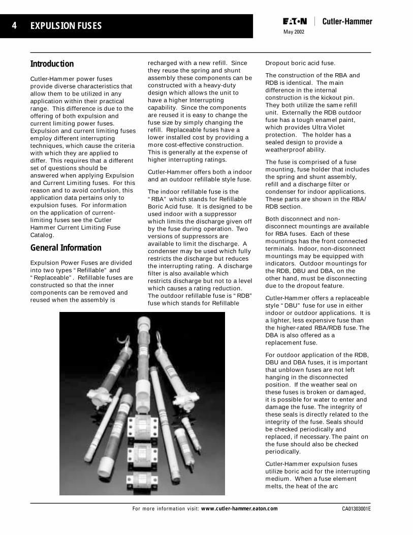
Expulsion Power Fuses are dividedinto two types “Refillable” and“Replaceable”. Refillable fuses areconstructed so that the innercomponents can be removed andreused when the assembly is
recharged with a new refill. Sincethey reuse the spring and shuntassembly these components can beconstructed with a heavy-dutydesign which allows the unit tohave a higher Interruptingcapability. Since the componentsare reused it is easy to change thefuse size by simply changing therefill. Replaceable fuses have alower installed cost by providing amore cost-effective construction.This is generally at the expense ofhigher interrupting ratings.
Cutler-Hammer offers both a indoorand an outdoor refillable style fuse.
The indoor refillable fuse is the“RBA” which stands for RefillableBoric Acid fuse. It is designed to beused indoor with a suppressorwhich limits the discharge given offby the fuse during operation. Twoversions of suppressors areavailable to limit the discharge. Acondenser may be used which fullyrestricts the discharge but reducesthe interrupting rating. A dischargefilter is also available whichrestricts discharge but not to a levelwhich causes a rating reduction.The outdoor refillable fuse is “RDB”fuse which stands for Refillable
Dropout boric acid fuse.
The construction of the RBA andRDB is identical. The maindifference in the internalconstruction is the kickout pin.They both utilize the same refillunit. Externally the RDB outdoorfuse has a tough enamel paint,which provides Ultra Violetprotection. The holder has asealed design to provide aweatherproof ability.
The fuse is comprised of a fusemounting, fuse holder that includesthe spring and shunt assembly,refill and a discharge filter orcondenser for indoor applications.These parts are shown in the RBA/RDB section.
Both disconnect and non-disconnect mountings are availablefor RBA fuses. Each of thesemountings has the front connectedterminals. Indoor, non-disconnectmountings may be equipped withindicators. Outdoor mountings forthe RDB, DBU and DBA, on theother hand, must be disconnectingdue to the dropout feature.
Cutler-Hammer offers a replaceablestyle “DBU” fuse for use in eitherindoor or outdoor applications. It isa lighter, less expensive fuse thanthe higher-rated RBA/RDB fuse. TheDBA is also offered as areplacement fuse.
For outdoor application of the RDB,DBU and DBA fuses, it is importantthat unblown fuses are not lefthanging in the disconnectedposition. If the weather seal onthese fuses is broken or damaged,it is possible for water to enter anddamage the fuse. The integrity ofthese seals is directly related to theintegrity of the fuse. Seals shouldbe checked periodically andreplaced, if necessary. The paint onthe fuse should also be checkedperiodically.
Cutler-Hammer expulsion fusesutilize boric acid for the interruptingmedium. When a fuse elementmelts, the heat of the arc

5
CA01303001E
May 2002
For more information visit: www.cutler-hammer.eaton.com
Technical Data
decomposes the boric acid whichthen produces water vapor and aninert boric anhydride which willextinguish the arc by blastingthrough it and exiting through thebottom of the fuse. The interruptionprocess produces both an exhaustand a good deal of noise. Tomoderate exhaust, a dischargefilter, muffler or condenser is addedto indoor fuses. Discharge filtersand mufflers limit the exhaust to asmall and relatively inert amount ofgas while lowering the noise level,but they have no effect on thefuse’s interrupting rating. Acondenser almost completelyabsorbs and contains the exhaustwhile further lessening the noiselevel; however, the condensercauses a reduction of the fuse’sinterrupting rating.
Fuse Selection
There are four factors involved inthe selection of a power fuse. Thefirst three considerations are thevoltage rating, the interruptingrating including rate of rise ofrecovery voltage considerations,and the continuous current rating ofthe fuse. Proper attention shouldbe given to each of theseconsiderations as improper
application in any one area mayresult in the fuse failing to performits intended function. The fourthconsideration is coordination withline and load side protectiveequipment that is needed to giveselectivity of outage and to preventpremature fuse blowing. Each ofthe four areas is discussed in detailin the following information.
Voltage Rating
The first consideration regardingfuse application is that the fuseselected must have a maximumdesign voltage rating equal to orgreater than the maximum normalfrequency recovery voltage whichwill be impressed across the fuseby the system under all possibleconditions. In most cases thismeans the maximum designvoltage of the fuse must equal orexceed the system maximum line-to-line voltage. The only exceptionto this rule occurs when fusingsingle-phase loads connected fromline-to-neutral of a four-wireeffectively grounded system. Herethe fuse maximum design voltageneed only exceed the systemmaximum line-to-neutral voltage
providing it is impossible under allfault conditions for the fuse toexperience the full line-to-linevoltage.
A good rule of thumb is that if morethan one phase of the system isextended beyond the fuse location,the fuse maximum design voltageshould equal or exceed the systemmaximum line-to-line voltageregardless of how the three-phasesystem is grounded on the sourceside of the fuse or how thetransformers or loads areconnected on the load side of thefuse. Many people, however,choose to fuse wye grounded wyetransformers with fuses that have avoltage rating which only exceedsthe system line-to-neutral voltage.In most cases this presents noproblems but the user should beaware of the remote possibility of asecondary phase-to-phaseungrounded fault which couldimpose full line-to-line voltageacross the fuse. When only onephase of a four-wire effectivelygrounded system is extendedbeyond the fuse to supply a loadconnected from phase-to-neutral, itis usually acceptable to have thefuse maximum design voltageequal or exceed the systemmaximum line-to-neutral voltage.
It is permissible for expulsion fusevoltage ratings to exceed thesystem voltage by any desiredamount but under nocircumstances may the systemvoltage exceed the fuse maximumdesign voltage.
Interrupting Rating
The rated interrupting capacity ofpower fuses is the rms value of thesymmetrical component (ACcomponent) of the highest currentwhich the fuse if able tosuccessfully interrupt under anycondition of asymmetry. In otherwords, the interrupting ratingdenotes the maximum symmetricalfault current permitted at the fuselocation.
Figure 1: Asymmetry Factor
Asy
mm
etry
Fac
tor
at 1
/2 C
ycle
1.7
1.6
1.5
1.4
1.3
1.2
1.1
Circuit X/R Ratio1 2 3 4 5 10 20 30 40 50
6May 2002
CA01303001EFor more information visit: www.cutler-hammer.eaton.com
Technical Data
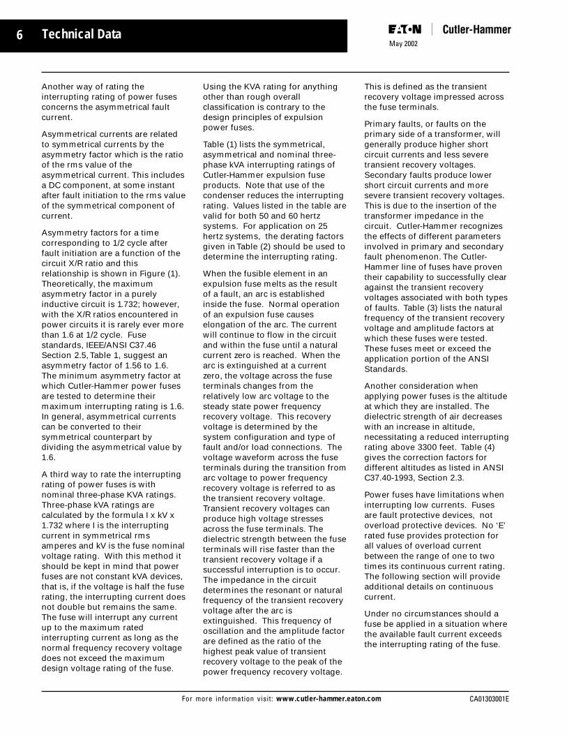
Another way of rating theinterrupting rating of power fusesconcerns the asymmetrical faultcurrent.
Asymmetrical currents are relatedto symmetrical currents by theasymmetry factor which is the ratioof the rms value of theasymmetrical current. This includesa DC component, at some instantafter fault initiation to the rms valueof the symmetrical component ofcurrent.
Asymmetry factors for a timecorresponding to 1/2 cycle afterfault initiation are a function of thecircuit X/R ratio and thisrelationship is shown in Figure (1).Theoretically, the maximumasymmetry factor in a purelyinductive circuit is 1.732; however,with the X/R ratios encountered inpower circuits it is rarely ever morethan 1.6 at 1/2 cycle. Fusestandards, IEEE/ANSI C37.46Section 2.5, Table 1, suggest anasymmetry factor of 1.56 to 1.6.The minimum asymmetry factor atwhich Cutler-Hammer power fusesare tested to determine theirmaximum interrupting rating is 1.6.In general, asymmetrical currentscan be converted to theirsymmetrical counterpart bydividing the asymmetrical value by1.6.
A third way to rate the interruptingrating of power fuses is withnominal three-phase KVA ratings.Three-phase kVA ratings arecalculated by the formula I x kV x1.732 where I is the interruptingcurrent in symmetrical rmsamperes and kV is the fuse nominalvoltage rating. With this method itshould be kept in mind that powerfuses are not constant kVA devices,that is, if the voltage is half the fuserating, the interrupting current doesnot double but remains the same.The fuse will interrupt any currentup to the maximum ratedinterrupting current as long as thenormal frequency recovery voltagedoes not exceed the maximumdesign voltage rating of the fuse.
Using the KVA rating for anythingother than rough overallclassification is contrary to thedesign principles of expulsionpower fuses.
Table (1) lists the symmetrical,asymmetrical and nominal three-phase kVA interrupting ratings ofCutler-Hammer expulsion fuseproducts. Note that use of thecondenser reduces the interruptingrating. Values listed in the table arevalid for both 50 and 60 hertzsystems. For application on 25hertz systems, the derating factorsgiven in Table (2) should be used todetermine the interrupting rating.
When the fusible element in anexpulsion fuse melts as the resultof a fault, an arc is establishedinside the fuse. Normal operationof an expulsion fuse causeselongation of the arc. The currentwill continue to flow in the circuitand within the fuse until a naturalcurrent zero is reached. When thearc is extinguished at a currentzero, the voltage across the fuseterminals changes from therelatively low arc voltage to thesteady state power frequencyrecovery voltage. This recoveryvoltage is determined by thesystem configuration and type offault and/or load connections. Thevoltage waveform across the fuseterminals during the transition fromarc voltage to power frequencyrecovery voltage is referred to asthe transient recovery voltage.Transient recovery voltages canproduce high voltage stressesacross the fuse terminals. Thedielectric strength between the fuseterminals will rise faster than thetransient recovery voltage if asuccessful interruption is to occur.The impedance in the circuitdetermines the resonant or naturalfrequency of the transient recoveryvoltage after the arc isextinguished. This frequency ofoscillation and the amplitude factorare defined as the ratio of thehighest peak value of transientrecovery voltage to the peak of thepower frequency recovery voltage.
This is defined as the transientrecovery voltage impressed acrossthe fuse terminals.
Primary faults, or faults on theprimary side of a transformer, willgenerally produce higher shortcircuit currents and less severetransient recovery voltages.Secondary faults produce lowershort circuit currents and moresevere transient recovery voltages.This is due to the insertion of thetransformer impedance in thecircuit. Cutler-Hammer recognizesthe effects of different parametersinvolved in primary and secondaryfault phenomenon. The Cutler-Hammer line of fuses have proventheir capability to successfully clearagainst the transient recoveryvoltages associated with both typesof faults. Table (3) lists the naturalfrequency of the transient recoveryvoltage and amplitude factors atwhich these fuses were tested.These fuses meet or exceed theapplication portion of the ANSIStandards.
Another consideration whenapplying power fuses is the altitudeat which they are installed. Thedielectric strength of air decreaseswith an increase in altitude,necessitating a reduced interruptingrating above 3300 feet. Table (4)gives the correction factors fordifferent altitudes as listed in ANSIC37.40-1993, Section 2.3.
Power fuses have limitations wheninterrupting low currents. Fusesare fault protective devices, notoverload protective devices. No ‘E’rated fuse provides protection forall values of overload currentbetween the range of one to twotimes its continuous current rating.The following section will provideadditional details on continuouscurrent.
Under no circumstances should afuse be applied in a situation wherethe available fault current exceedsthe interrupting rating of the fuse.

7
CA01303001E
May 2002
For more information visit: www.cutler-hammer.eaton.com
Technical Data
Continuous Current Rating
Power fuses are designed so thatthey can carry their rated currentcontinuously without exceeding thetemperature rises permitted byNEMA and ANSI standards. Thecontinuous current ratings availablein Cutler-Hammer fuses are shownin Table (5). These current ratingscarry an ‘E’ designation defined inANSI C37.40-1993 to C37.47-1981.
The current-responsive element ofa power fuse rated 100 E amperesor below shall melt in 300 secondsat a rms current within the range of200 % to 240 % of the continuouscurrent rating.
The current-responsive elementwith ratings above 100 amperesshall melt in 600 seconds at an rmscurrent within the range of 220% to264% of the continuous currentrating of the fuse unit, refill unit, orfuse link.
Although the ‘E’ rating does notmake time-current curves identical,it does produce a similarity amongdifferent manufacturer’s fuses, asthey all must satisfy the aboverequirements. The ‘E’ rating alsoreflects the 2:1 minimum meltingcurrent versus continuous currentrating ratio which is a designfeature of power fuses resultingfrom the average requirements ofgeneral purpose high voltage fuseapplications and inherent featuresof conventional fuses.
As previously mentioned, powerfuses are designed to continuouslycarry their rated current withoutexceeding temperature riserestrictions. If the rated current isexceeded by a small amount, anoverload situation is encountered.An overload situation is when thefuse is subjected to a current belowthe 300 or 600 second meltingcurrent but substantially above thecontinuous current rating for anexcessive length of time. This typeof condition generates a largeamount of heat and may causedamage to the fuse. This problem
Voltage kV Interrupt Ratings
Nominal Max. Sym. Asym. 3-Phase Sym. Asym. 3-Phase Design Amps Amps Sym. MVA Amps Amps Sym. MVA
RBA-RDB-200 RBA-RDB-200 Indoor with Discharge Filter RBA-200 Indoor with Condenser2.40 2.75 19,000 30,000 80 10,000 16,000 424.16 4.80 19,000 30,000 137 10,000 16,000 724.80 5.50 19,000 30,000 158 10,000 16,000 837.20 8.25 16,600 26,500 205 10,000 16,000 125
13.80 14.40 14,400 23,000 345 8,000 12,800 19114.40 15.50 14,400 23,000 360 8,000 12,800 20023.00 25.50 10,500 16,800 420 6,300 10,100 25034.50 38.00 6,900 11,100 410 5,000 8,000 300
RBA-RDB-400 RBA-RDB-400 Indoor with Discharge Filter RBA-400 Indoor with CondenserRBA-RDB-800 RBA-RDB-800 Indoor with Discharge Filter RBA-800 Indoor with Condenser
2.4 2.75 37,500 60,000 150 20,000 32,000 844.16 4.80 37,500 60,000 270 20,000 32,000 1444.8 5.50 37,500 60,000 310 20,000 32,000 1667.2 8.25 29,400 47,000 365 16,000 25,600 200
13.8 14.40 36,000 57,600 859 12,500 20,000 30014.4 15.50 29,400 47,000 730 12,500 20,000 31223.0 25.50 21,000 33,500 840 10,000 16,000 40034.5 38.00 16,800 26,800 1000 10,000 16,000 600
DBU DBU Outdoor Vented DBU Indoor with Muffler2.4 2.75 14,000 22,400 58 14,000 22,400 584.16 4.80 14,000 22,400 100 14,000 22,400 1004.8 5.50 14,000 22,400 116 14,000 22,400 1167.2 8.25 14,000 24,000 174 14,000 22,400 174
13.8 14.4 14,000 22,400 334 14,000 22,400 33414.4 17.1 14,000 22,400 349 14,000 22,400 34923.0 27.0 12,500 20,000 500 12,500 20,000 50034.5 38.0 10,000 16,000 600 8,000 12,500 500
DBA-1 DBA-1 Outdoor Vented2.4 2.75 6,300 10,100 26 …… …… …4.16 4.80 6,300 10,100 45 …… …… …4.8 5.50 6,300 10,100 52 …… …… …7.2 8.25 6,300 10,100 78 …… …… …
13.8 14.40 6,300 10,100 150 …… …… …14.4 15.50 6,300 10,100 157 …… …… …23.0 25.50 6,300 10,100 251 …… …… …34.5 38.00 5,000 8,000 298 …… …… …46.0 48.30 4,000 6,400 318 …… …… …69.0 72.50 2,500 4,000 298 …… …… …
DBA-2 DBA-2 Outdoor Vented23.0 25.50 12,500 20,000 497 …… …… …34.5 38.00 12,500 20,000 746 …… …… …46.0 48.30 12,500 20,000 995 …… …… …69.0 72.50 10,000 16,000 1,194 …… …… …
Table 1: Expulsion Fuse Interrupting Ratings
is less severe in the DBU and RBA/RDB standard fuses as they employsilver elements which are, for allpractical purposes, undamageable;however, caution should still beexercised when overloading the fuseas the heat generated may producedeterioration of the boric acidinterrupting medium and charring ofthe fuse wall before the fuse element
melts. Figure (2) gives overloadcharacteristics of Cutler Hammerexpulsion fuses. Do not exceedthese overload restrictions underany circumstances.
In the practical application ofexpulsion power fuses they areused to protect transformers andother equipment where overloadsand inrush currents are common.

8May 2002
CA01303001EFor more information visit: www.cutler-hammer.eaton.com
As mentioned above, expulsionfuses have a rather low thermalcapacity and cannot carry overloadsof the same magnitude andduration as motors andtransformers of equal continuouscurrents. For this reason a generalfuse application ratio of 1.4:1 fusecontinuous current rating to fullload current is suggested so thefuse will not blow on acceptableoverloads and inrush conditions.Remember that this ratio is ageneral figure for typicalapplications and that a ratio as lowas 1:1 can be used if the systemcurrent will never exceed the ratedcurrent of the fuse or a much higherratio may be needed in otherspecific applications. More specificapplication information can befound in the individual equipmentapplication sections that follow.
At times it is desirable to have acontinuous current rating largerthan any single fuse can provide.Higher ratings may be obtained byparalleling fuses. This practice maybe extremely dangerous if the fusesare arbitrarily paralleled as theprobability is great that the fuseelements of paralleled expulsionfuses will not melt at the sameinstant. An occurrence of thisnature creates a situation in whichthe progress of the springaccelerating arcing rod of each ofthe fuses in parallel will not beuniform. Such a situation couldcause a restrike in one of the fuseswith the total arcing energy in thatfuse exceeding the design level andresulting in a failure to clear thecircuit. Under no circumstancesshould fuses be paralleled unlessthe paralleling is the extensivelytested Cutler Hammer design or thespecific application receivesengineering approval from theTechnical Center.
Corrections for applying expulsionfuses above 3300 feet apply to thecontinuous current rating as well asthe interrupting rating. Refer toTable (4) in this section forcorrection factors for differentaltitudes as listed in IEEE/ANSI
C37.40-1993, Section 2.3.
Remember that under nocircumstances must the continuousrating be less than the continuousload current and that ‘E’ rated fusesmay not provide protection forcurrents in the range of one or twotimes the continuous current rating.
Coordination
In addition to selecting a fuse thatmeets the voltage, interrupting andcontinuous current ratings, it isimportant to examine the meltingand total clearing time-currentcharacteristics of the fuse. Themelting characteristics areexpressed as time-currentrelationships. These relationshipsare designated as minimum melt
Table 2: Derating Factors for 25 Hz
To find the interrupting rating at 25 hertz multiply the desired rating from Table 1 by the appropriate value from thefollowing list.
Voltage kV Derating Factors
RBA-200 RDB-400 RBA-400Nominal Max. RDB-200 RBA-800 DBA-1
Design DBU RDB-800 DBA-2
2.40 2.75 .45 .37 .754.16 4.80 .45 .37 .754.80 5.50 .45 .37 .757.20 8.25 .45 .37 .70
13.80 14.40 .47 .35 .7014.40 15.50 .47 .35 .7023.00 25.50 .53 .35 .6034.50 38.00 .69 .40 .6246.00 48.30 … … .6769.00 72.50 … … .71
Table 3: Transient Recovery Voltage Values for RBA, RDB and DBU Fuses Voltage kV Transient Recovery Voltage Values
Primary Fault SecondaryRecovery Amplitude Fault Recovery Amplitude
Nominal Max. Frequency Factor Frequency FactorDesign in kHz in kHz
2.40 2.75 9.0 1.6 26.0 1.64.16 4.80 9.0 1.6 26.0 1.6
4.80 5.50 9.0 1.6 26.0 1.67.20 8.25 9.0 1.6 26.0 1.6
13.80 14.40 5.5 1.6 17.4 1.614.40 15.50 5.5 1.6 17.4 1.623.00 25.50 4.2 1.6 13.0 1.634.50 38.00 3.9 1.6 8.5 1.6
Altitude (above sea level) Correction Factor
Interrupting ContinuousRating Current
Feet Meters Times Times
3,300 1,000 1.00 1.004,000 1,200 .98 .995,000 1,500 .95 .996,000 1,800 .92 .987,000 2,100 .89 .988,000 2,400 .86 .979,000 2,700 .83 .96
10,000 3,000 .80 .9612,000 3,600 .75 .9514,000 4,300 .70 .9316,000 4,900 .65 .9218,000 5,500 .61 .9120,000 6,100 .56 .90
Table 4: Altitude Corrections from ANSI C37.40-1993, Section 2.3
Technical Data

9
CA01303001E
May 2002
For more information visit: www.cutler-hammer.eaton.com
curves and as total clearing curves.The minimum melt curve gives theminimum amount of time inseconds required to melt the fuseelements at a particular value ofsymmetrical current under specifiedconditions. Total clearing curves
give the maximum amount of timein seconds to complete interruptionof the circuit at a particular value ofsymmetrical current under specifiedconditions. Arcing time is definedas the amount of time in cycleselapsing from the melting of thefusible element to the finalinterruption of the circuit. It isimportant to examine thesecharacteristics to assure properprotection and selectivity with otherovercurrent protective devices.These curves are located in eachfuse section of this catalog.
The minimum melt curve of all ‘E’rated fuses must lie within therange defined in ANSI C37.46-1981at either the 300 or 600 secondpoint, but there are no limitationsplaced on the melting time at highcurrents. To take advantage of this,Cutler Hammer increases theapplicability of their fuses byproducing a ‘fast’ or ‘standard’ fuseand a ‘slow’ or ‘time-lag’ fuse. Thecurves for the ‘time-lag’ fuse areless inverse and allow for more of atime delay at high currents.
Low currents below the 300 or 600second melting current are termedoverload currents. Overloadcurrents are discussed in thesection on continuous currentrating where Figure (2) gives thefuse overload characteristics thatshould not be exceeded under any
circumstances.
Properly coordinating power fusesis basically a problem of keepingthe fuse minimum melting curveabove the total clearing curve ofany downstream overcurrentprotective device, and keeping thetotal clearing curve beneath theminimum melting curve of anyupstream protective device.Manufacturer’s published time-current curves are based onstandard conditions and do notallow for such variables aspreloading or ambient temperature.For this reason, it is recommendedthat a safety zone be used whencoordinating power fuses so propercoordination is maintained evenwhen there are shifts in the curvesdue to changes in the abovementioned variables. There are twoapproaches used to achieve thissafety zone and both producesimilar results. One approachemploys a 25 percent safety zone intime for a given value of currentand the other uses a 10 percentsafety zone in current for a givenvalue of time. Cutler Hammer usesthe second method as it allows thesafety band to be published on theleft-hand side of all the time-currentcurves. Coordination is thenachieved by overlaying curves andshifting one by the width of thepublished safety zone.
Figure 3: Preloading Adjustment Factor for Power Fuses
Figure 2: Overload Characteristics forCutler-Hammer Expulsion Fuses
Technical Data
Hours
4
3
2
1
1/2
Seconds1000
600
300
100
1 2 3
100% of Fuse Rating
AverageMelting Curves
Above 100 Amps
100 Amps or Less
6
Load Current in Percent of Fuse Ampere Rating
Mel
ting
Tim
e in
Per
cent
of T
ime
Show
n on
Tim
e -
Curr
ent C
hara
cter
istic
Cur
ve
Fuses Above 100 Amps
P
Fuses 100 Amps and Less
F
100
50
050 100 150 200 2500

10May 2002
CA01303001EFor more information visit: www.cutler-hammer.eaton.com
When discussing coordination andtime-current curves, it should bepointed out that IEEE/ANSIStandards C37.46-1981, Section3.1.1 allows the total clearingcurves to be drawn at a distancecorresponding to 20 percent on thescale to the right of the minimummelting curve. Cutler Hammer usesthis 20 percent figure in itspublished curves but testing hasverified that a 10 percent toleranceis more than sufficient for allcurrents less than that whichcauses melting in .5 seconds for agiven fuse rating.
If desired or if unusual conditionsexist, shifts in the time-currentcurve due to pre-loading may beexamined individually. CutlerHammer time-currentcharacteristics are derived fromtests on fuses in an ambient of 25degrees C and no initial loading asspecified in IEEE/ANSI C37.46-1981.Fuses subject to conditions otherthan the above will experienceshifts in the time-current curves.Figure (3) gives the adjusting factorfor preloaded fuses. Theseadjusting factors are valid only forCutler Hammer power fuses.
Figure (4) gives an example oftightly coordinated fuse application.The figure shows a standard speedRBA fuse protecting the primary ofa 1000 KVA transformer with CutlerHammer type DS low voltage, aircircuit breakers protecting thesecondary equipment.
Coordination with reclosing circuitbreakers may be performed with
the aid of the coordination chartfound on page 16, Figure (7). Thiscurve is explained under theRepetitive Fault Section of thiscatalog section.
Application
When applying expulsion fuses,physical as well as electricalproperties must be considered. Bytheir nature, expulsion fuses emitgases from the bottom of the fuse.Care should also be given tomaintaining minimum phase-to-phase and phase-to-ground spacingwhen mounting the fuse. Indoorfuses employ either a dischargefilter, muffler or a condenser, butspecified clearances must still bemaintained. Outdoor fuses arevented and thus have a high noiselevel and expel a greater amount ofgas making clearance from groundan important consideration. Whenapplying outdoor fuses, space mustbe allowed for the arc the fuseswings through during dropout.Table (6) gives the minimumclearance to ground and theminimum phase spacing.
Outdoor fuses, as mentioned aboveare vented. The venting of the hotgases resembles a cylindricalcolumn in nature. Height above theminimum ground clearance is notreally a factor except as related torebounding from the ground of hotparticles and gases. Figure (5)shows the nature of the dischargeand allows the user to suggestspecific safety zones for eachparticular application.
Transformer Application
One of the more commonapplications of power fuses is toprotect the primary of transformers.When selecting a fuse to beinstalled at the primary terminals ofa transformer, all application rulesconcerning voltage rating andinterrupting rating as mentioned inprevious sections should befollowed. This section is concernedprimarily with the selection of thefuse continuous current rating.Details discussed in this section willbe general. A more detaileddiscussion of how the fusecontinuous current rating should bedetermined is given in Appendix 1.
Fuses at the primary of atransformer should not blow ontransformer magnetizing or in-rushcurrent, nor should they blow ordeteriorate under long durationoverloads to which the transformeris subjected in normal service andin cases of emergency. On theother hand, they must protect thetransformer against short circuits.These considerations usuallydetermine the upper and lower limitof the fuse rating. Coordinationwith other protective devices on thesystem, such as secondarybreakers, often places furtherrestrictions on the fuse to beselected. In general, however, aknowledge of transformer typeallows the fuse continuous currentrating to be chosen on the basis ofa multiple of full load current.
Table 5: Continuous Current Ratings Available in Cutler-Hammer Expulsion Fuses
Max Design RBA-RDB-200 RBT-200 RBA-RDB-400 RBT-400 DBU DBU DBU DBA-1, 2kV Standard Time Lag Standard1 Time Lag Standard Slow K-Rated Standard
2.75 10E to 200E 20E to 200E 0.5E to 400E1 20E to 400E15.50 10E to 200E 20E to 200E 0.5E to 400E1 20E to 400E18.25 10E to 200E 20E to 200E 0.5E to 400E1 20E to 400E1 0.5E to 200E
14.40 10E to 200E 20E to 200E 0.5E to 400E1 20E to 400E1 5E to 200E 15E to 200E 3K to 200K 0.5E to 200E15.50 10E to 200E 20E to 200E 0.5E to 400E1 20E to 400E1 5E to 200E 15E to 200E 3K to 200K 0.5E to 200E25.50 10E to 200E 20E to 200E 0.5E to 300E2 20E to 300E2 5E to 200E 15E to 200E 3K to 200K 0.5E to 200E38.00 10E to 200E 20E to 200E 0.5E to 300E2 20E to 300E2 5E to 200E 15E to 200E 3K to 200K 0.5E to 200E
1 Using the 2 paralleled 800 fuse design, which has a 10% derating factor, ratings of 450, 540 and 720 are available.
Application Data

11
CA01303001E
May 2002
For more information visit: www.cutler-hammer.eaton.com
In the routine process of applyingfuses on the basis of transformerKVA rating, it is assumed thatadequate secondary protection isprovided. The ordinary procedurethen is to employ a fuse rating suchthat overheating due to inrush orpermissible overloads does notdamage the fuse. Assuming thetransformer to be protected is self-cooled and that the maximum 1.5hour overload on the transformerwould not exceed 200 percent ofthe transformer rating, then theminimum ratio of fuse currentrating to transformer full loadcurrent should be 1.2:1.
Thus, a fuse rating is chosen bymultiplying the transformer fullload rating by 1.4 and thenselecting the fuse which has acontinuous current rating of thatvalue. If there is no fuse ratedexactly 1.4 times the transformersfull load rating, the next largerrated fuse should be selected.
Tables (7A) and (7B) give suggestedfuse ratings for single phase andthree-phase power transformersbased on the 1.4:1 ratio given above.
It should be remembered that the1.4:1 ratio is a general value, whichmay be varied, in specific cases.Dry type transformers, for instance,have a smaller overload capacityand permit fusing closer to the fullload rating while distributiontransformers are traditionallyoverloaded more severely andcould require a fusing ratio as largeas 2:1. Further, if provisions aremade by thermal relays orotherwise to limit transformeroverloads to a lower range, theratio can be reduced. If atransformer has provisions forforced cooling, then the applicationratio should be 1.2:1 for the fuserating to the forced cooled rating.
Magnetizing inrush is the otherfactor the fuse must be able towithstand without damage. Themagnitude of inrush may vary but,in general, is of magnitude 12 timesthe transformer full load rating for a1/10 of a second duration. Inrushshould not present a problem forany applications using a ratio aslow as 1:1. If, however, there areany extenuating circumstances or
questions, then refer to theappropriate time-current curvesand check to see that the inrush,magnitude and duration nevercross the fuses’ minimum meltingcurve.
Remember that a fuse must not beapplied where it can realize acontinuous current greater than itsrating and that the fuse may notprovide protection for currents inthe range of one or two times thecontinuous current rating. Refer tothe continuous current section orAppendix 1 for further information.
Capacitor Application
Another common use of powerfuses is for the protection ofcapacitor banks. This application isunique in that the protectedequipment, capacitors, aredesigned with a zero minustolerance and some value ofpositive tolerance. For this reasona ratio of 1.65:1 fuse rating to fullload current is suggested for allsingle bank protection. If two ormore banks are paralleled withautomatic switching, refer to theTechnical Center for fusinginformation.
Repetitive Faults
It is often desirable to determinethe performance of fuses underrepetitive faults such as producedby the operation of reclosing circuitbreakers. This performance isdetermined by graphicallysimulating the fuses’ heating andcooling characteristics, which arefound in and expressed by themelting time-current curves. Thetheory behind the aboveimplications is available uponrequest, but in this section only thepractical use of those implicationswill be discussed.
Conventional ‘E’ rated fuses can withgood approximation be regarded asbodies whose heating and coolingproperties are described by the basicexponential curves A and B asshown in Figure (6). Except for
LD LD SD SD IBreaker Amp PU T PU T PU
Figure 4: Typical Fuse Coordination
BDS-416 1200 IX 4 Sec 4X .18 Sec 12XCCDS-206 400 IX 20 Sec … …… 9X
Application Data
C B A
MinimumMelt
TotalClearing
1000800600
400
200
1008060
40
20
1086
4
2
1.8.6
.4
.2
.1
.08
.06
.04
.02
.01
Scale x 10 = Secondary Current in Amperes
40 60 80 100
200
400
600
800
1000
2000
4000
6000
8000
1000
0
Tim
e in
Sec
on
ds
1000800600
400
200
1008060
40
20
1086
4
2
1.8.6
.4
.2
.1.08.06
.04
.02
.01
A
4.8 KV
RBA200E
B
1000 KVA
480 VDS-4161200 LSI
CC CDS-206400 LI

12May 2002
CA01303001EFor more information visit: www.cutler-hammer.eaton.com
being inverted, the cooling curve isthe same as the heating curve asboth have the same time constant.Each fuse has a specific timeconstant which can be calculatedwith sufficient accuracy by theformula θ = .1S2 where S is themelting current at .1 secondsdivided by the melting current at300 or 600 seconds. The 300seconds applies for fuses rated 100amperes or less and the 600seconds for fuses rated above 100amperes.
The time constant of a specific fuse,having been obtained in terms ofseconds, gives to the generalheating and cooling curves ofFigure (6) a specific time scale. Inenables us to plot the course of thefuse temperature (in percentvalues) if we know the sequenceand duration of the open andclosed periods of the recloser. Thisis illustrated by Curve C that isformed by piecing together theproper sections of Curves A and B.
Next we must determine thetemperature at which the fuse willmelt. Here we refer to the standardtime-current curves and find themelting time M for a specific valueof fault current. The meltingtemperature Tm lies where theordinate to the time M intersectsCurve A. It is not necessary toknow the absolute value of this
temperature, as it is sufficient toknow its relation to the peaks. Asimilar temperature Tn can be foundusing the total clearing time for thespecific fault current. What wehave then are two temperatureswhere we can state that any timethe fuse Curve C intersects line Tm,the fuse could blow and any time itintersects line Tn, the fuse willdefinitely blow. The gap betweenTm and Tn indicates the tolerancerange as set forth in ANSI andNEMA standards where ‘E’ ratedfuses are defined.
If the fuse is not to blow, Curve Cmust remain below the level Tm bya safe margin. It is commonpractice to provide such a safetymargin by coordinating the breakerwith a fuse curve whose timeordinates are 75 percent of those ofthe melting curve. Line Ts
represents this temperature onFigure (6).
Although the construction of thetemperature diagram as outlinedabove basically offers nodifficulties, the manipulation ismade easier and more accurate byputting the graph on semi-logcoordinates as shown in Figure (7).On these coordinates the coolingcurve B becomes a straight line.
Figure 5: Nature of Expulsion Fuse Discharge
Application Data
Vapor CloudsMay Rebound From Ground
Extending To 10 Feet
VentEndof
Fuse
IntenseDischarge
Up To3 Ft.
Clouds Of Water VaporUp To 6 Ft.Innocuous
GasesInnocuous
Gases

13
CA01303001E
May 2002
For more information visit: www.cutler-hammer.eaton.com
APPENDIX 1
Transformer Application
This appendix is to supplement theinformation presented in the“Transformer Application” sectionof this catalog. If generalinformation is all that is required,then the section in the body of the“Transformer Application Data”should be sufficient. This appendixis an extension of that section andis more specific and detailed.
When selecting fuses to be installedat the primary terminals of atransformer, an understanding ofthe purpose of the fuse will aid inunderstanding the selectionprocess. The purposes of the fusein the order of their importance areas follows:
■ Protect the system on the sourceside of the fuses from an outagedue to faults in or beyond thetransformer.
■ Override (coordinate with)protection on the low-voltageside of the transformer.
■ Protect the transformer againstbolted secondary faults.
■ Protect the transformer againsthigher impedance secondaryfaults to whatever extent ispossible.
The selection process involveschoosing the proper voltage,interrupting and continuous currentratings for the fuse. Applicationrules pertaining to voltage andinterrupting rating arestraightforward and are sufficientlycovered in their respective sections.Selecting the fuse continuouscurrent rating, which best fulfillsthe purpose hierarchy listed abovecan be more involved and will bediscussed in detail in this section,due to faults in or beyond thetransformer.
There are two major areas ofconcern when selecting acontinuous current rating for thefuse, which is to protect atransformer. The rating must belarge enough to prevent false orpremature fuse interruption frommagnetizing or inrush currents andit must also be large enough to
prevent fuse damage or fuseinterruption during normal oremergency overload situations.Remembering the aboverestrictions, the fuse rating mustalso be small enough to provide theprotection listed in the purposehierarchy. Inrush, overloading andsuggested minimum and maximumratings will be the topic of theremainder of the appendix.
Fuses on the primary side oftransformers should not blow ontransformer magnetizing or inrushcurrent. The magnitude of the firstloop of inrush current and the rate atwhich the peaks of subsequent loopsdecay is a function of many factors.They are transformer design, residualflux in the core at the instant ofenergization, the point on the voltagewave at which the transformer isenergized and the characteristics ofthe source supplying the transformer.When energizing, the heating effectof the inrush current in an expulsionfuse can be considered equal to 12times the transformer full loadcurrent flowing for 1/10 of a second.Thus, when selecting the currentrating for fuses used at the primaryside of a transformer, the fuse
Appendix 1
Max. RBA Disconnect RBA Non-Disconnect RDBDesign DBU DBA
kV 200/400 800 200/400 800 200/400 800
2.75 11.75 27.51 11.16 19.92 18.0 26.76 17.0 17.04.80 11.75 27.51 11.16 19.92 18.0 26.75 17.0 17.05.50 11.75 27.51 11.16 19.92 18.0 26.75 17.0 17.08.25 13.25 29.01 12.56 21.32 18.0 26.76 17.0 17.0
14.40 14.75 30.51 13.06 21.82 24.0 32.76 19.0 19.015.50 16.25 32.01 15.56 24.32 24.0 32.76 19.0 19.025.50 20.25 … 19.56 … 30.0 38.76 23.0 23.038.00 25.25 … 24.56 … 36.0 44.76 30.0 30.048.30 … … … … … … … 33.072.50 … … … … … … … 44.0
A - Recommended phase to phase centerline spacing without barriers in inches
Max. Design kV RBA Filter RBA RDB-200, DBU & DBA-1 RDB-400, 800 & DBA-2Condenser Vented Vented
2.75 7.5 3.0 17.5 22.04.80 7.5 3.0 17.5 22.05.50 8.5 4.0 17.5 22.08.25 8.5 4.0 17.5 22.0
14.40 11.5 6.0 21.0 26.015.40 11.5 6.0 21.0 26.025.50 15.0 8.5 26.0 32.038.00 19.5 12.0 33.0 42.048.30 (DBA only) …… …… 40.0 54.072.50 (DBA only) …… …… 54.0 84.0
B - Minimum clearance to ground in inches
Table 6: Recommended Spacings
Typical Single Fuse Unit
TypicalParalleledFuse UnitWith StandardCutler-HammerMounting
A
B
Typical Filter or Condenser
A = MinimumClearanceto Ground
A
B
Typical Vented
B = RecommendedPhase to PhaseCenterlineSpacing WithoutBarriers
400 800
400 800

14May 2002
CA01303001EFor more information visit: www.cutler-hammer.eaton.com
minimum-melting curve must lieabove and to the right of the point onthe time-current curve correspondingto 12 times full load current and 0.1seconds. The fuse whose minimummelting curve lies just above and tothe right of this point is the lowestrated fuse, which can be used at theprimary terminals. This criterion isusually satisfied for all Cutler-Hammer expulsion fuses if the fusecurrent rating is equal to or greaterthan the transformer self-cooled fullload current. Thus, a fusing ratio aslow as 1:1 could be used in selectingprimary side fuses if inrush ormagnetizing current were the onlyconcern.
It is common practice for mostsystem operators to overload theirtransformers for short periods oftime during normal and emergencysituations. To allow this flexibility, it isnecessary to select a fuse that cancarry the overload without beingdamaged. When this is taken intoaccount, a fusing ratio higher than1:1 is almost always required whenapplying fuses for transformerprotection. The fuse emergencyoverload curve (Figure 2 in theTechnical Section) along with aknowledge of the extent to whichthe transformer will be overloadedis used as a basis for determiningthe smallest fuse which can beapplied. The fuse rating isdetermined by using the duration ofthe transformer overload on theoverload curve (ordinate value) toobtain a multiple of current rating,which should not be exceeded. Ifthe transformer overload current isthen divided by the multipleobtained from the overload curve.The result is the minimum fusecurrent rating. Select the fuserating which equals or, is just largerthan, this value. The allowabletime duration of the current in theprimary side fuses duringtransformer overload should neverexceed the values shown by thefuse overload curve in Figure 2.
Suggested minimum fuse sizes forprotection of self-cooledtransformers are given in Tables
(7A) and (7B) which are found inthis Appendix. These tables werebased on the premise that themaximum 1.5-hour overload on thetransformer would not exceed 200percent of the transformer rating.This overload condition requiresthat the minimum ratio of fusecurrent rating to transformer fullload current is 1.4:1. Fuse sizeslisted in Tables (7A) and (7B) arethose which are just higher than 1.4times the transformer full loadcurrent. If higher or longer
duration transformer overloads areto be permitted, a fuse with ahigher continuous current ratingmay be required. The proceduredescribed in the previousparagraph should then be used tofind the smallest permissible fusesize.
If provisions are made, by thermalor other protective devices, to limittransformer overloads to a lowerrange, the ratio of fuse current totransformer full load current can be
Table 7A - Suggested Minimum Expulsion Fuse Current Ratings for Self-Cooled2.4 to 12.0 kV Power Transformer Applications
1 Two (2) 300 E Ampere fuse refills used in parallel with 10% derating factor.2 Two (2) 400 E Ampere fuse refills used in parallel with 10% derating factor.3 Two (2) 250 E Ampere fuse refills used in parallel with 10% derating factor.
Appendix 1
Nom. kV 2.4 4.16 4.8 7.2 12.0
Fuse Max. kV 8.3 8.3 8.3 8.3 15.5
Transformer Full Fuse Full Fuse Full Fuse Full Fuse Full FuseFull Load E-Ampere Load E-Ampere Load E-Ampere Load E-Ampere Load E-Ampere
kVA Rating Current Rating Current Rating Current Rating Current Rating Current RatingSelf-Cooled Amps Amps Amps Amps Amps
Three Phase Transformers
9 2.16 3E 1.25 3E 1.10 3E 0.72 3E 0.43 3E15 3.60 5E 2.08 3E 1.80 3E 1.20 3E 0.72 3E30 7.20 10E 4.20 7E 3.60 5E 2.40 5E 1.44 3E45 10.80 15E 6.20 10E 5.40 10E 3.60 5E 2.16 3E75 18.00 25E 10.40 15E 9.00 15E 6.00 10E 3.60 5E
112 27.00 40E 15.60 25E 13.60 20E 9.00 15E 5.40 10E150 36.00 50E 20.80 30E 18.00 25E 12.00 20E 7.20 10E225 54.00 80E 31.30 50E 27.20 40E 18.00 25E 10.80 15E300 72.00 100E 41.60 65E 36.00 50E 24.00 40E 14.40 20E500 120.00 200E 69.40 100E 60.00 100E 40.00 65E 24.10 40E
750 180.00 250E 104.00 150E 90.00 125E 60.00 100E 36.10 50E1,000 241.00 400E 140.00 200E 120.00 200E 80.00 125E 48.10 80E1,500 360.00 540E1 208.00 300E 180.00 250E 120.00 200E 72.00 100E2,000 481.00 720E2 278.00 400E 241.00 400E 160.00 250E 496.20 150E2,500 600.00 … 346.00 540E1 301.00 450E3 200.00 300E 120.00 200E3,750 … … … … … … … … 180.00 250E5,000 … … … … … … … … 241.00 400E
Single Phase Transformers
5 2.08 3E 1.20 3E 1.04 3E 0.69 3E 0.416 3E10 4.17 7E 2.40 5E 2.08 3E 1.39 3E 0.832 3E15 6.25 10E 3.60 5E 3.13 5E 2.08 3E 1.25 3E25 10.40 15E 6.00 10E 5.20 10E 3.47 5E 2.08 3E37 15.60 25E 9.00 15E 7.80 15E 5.21 10E 3.12 5E
50 20.80 30E 12.00 20E 10.40 15E 6.95 10E 4.16 7E75 31.30 50E 18.00 25E 15.60 25E 10.40 15E 6.25 10E
100 41.70 65E 24.00 40E 20.80 30E 13.90 20E 8.32 15E167 70.00 100E 40.00 65E 35.00 65E 23.20 40E 13.90 20E250 104.00 150E 60.00 100E 52.00 80E 34.80 50E 20.80 30E
333 139.00 200E 80.00 125E 69.50 100E 46.30 65E 27.70 40E500 208.00 300E 120.00 200E 104.00 150E 69.60 100E 41.60 65E667 278.00 400E 160.00 250E 139.00 200E 92.60 150E 55.40 80E
833 347.00 540E1 200.00 300E 173.00 250E 115.50 200E 69.40 100E1,250 521.00 720E2 300.00 540E1 260.00 400E 174.00 250E 104.00 150E

15
CA01303001E
May 2002
For more information visit: www.cutler-hammer.eaton.com
less than 1.4:1. To find the amountof reduction permissible withoutdamage to the fuse, the procedureusing the overload curve should beemployed.
When the transformer has forcedcooling, the minimum fuse size,which can be applied, should bebased on the transformer top ratingand the extent to which thetransformer will be overloadedbeyond the top rating.
It should be remembered that an ‘E’rated expulsion fuse applied at theprimary terminals of a transformer
might not provide protection ofcurrents between one and twotimes the continuous current ratingof the fuse. That is, for currents inthis range which exceed the timelimits shown by the fuse overloadcurve in Figure (2), the fuse may bedamaged before the fusibleelement melts. In order to providedependable overload protection forthe transformer, protection must beapplied on the secondary side ofthe transformer.
Up to now the discussion of fusesapplied at the primary terminals ofa transformer has been concerned
with the lower limit of continuouscurrent rating, which can be safelyapplied. Equal concern should begiven to the upper limit ofcontinuous current rating, whichwill provide protection for thetransformer. The extent to whichthe fuses are to protect thetransformer against secondaryfaults is one of several factors,which determines the upper limit.Increasing the primary fuse size toallow for higher overloadsdecreases the protection affordedthe transformer and vice-versa.Usually thru-fault protection isprovided to the transformer by a
Appendix 1
System13.2 13.8 14.4 22.9 23.9 24.9 34.5 Nom. kV
15.5 15.5 15.5 25.5 25.5 25.5 38.0 Fuse Max. kV
Full Fuse Full Fuse Full Fuse Full Fuse Full Fuse Full Fuse Full Fuse TransformerLoad E-Ampere Load E-Ampere Load Ampere Load Ampere Load Ampere Load Ampere Load Ampere kVA Rating
Current Rating Current Rating Current Rating Current Rating Current Rating Current Rating Current Rating Self-CooledAmps Amps Amps Amps Amps Amps Amps
Three Phase Transformers
0.40 3E 0.38 3E 0.36 1⁄2E 0.22 1⁄2E 0.21 1⁄2E 0.20 1⁄2E 0.15 1⁄2E 90.66 3E 0.62 3E 0.60 3E 0.38 3E 0.36 1⁄2E 0.35 1⁄2E 0.25 1⁄2E 151.32 3E 1.25 3E 1.20 3E 0.75 3E 0.72 3E 0.69 3E 0.50 3E 301.98 3E 1.88 3E 1.80 3E 1.14 3E 1.09 3E 1.04 3E 0.75 3E 453.30 5E 3.10 5E 3.00 5E 1.89 3E 1.81 3E 1.74 3E 1.25 3E 75
4.95 7E 4.70 7E 4.51 7E 2.84 5E 2.72 5E 2.60 5E 1.88 3E 112.56.56 10E 6.20 10E 6.01 10E 3.78 7E 3.62 5E 3.47 5E 2.51 5E 1509.90 15E 9.40 15E 9.02 15E 5.68 10E 5.44 10E 5.21 10E 3.77 7E 225
13.10 20E 12.50 20E 12.00 20E 7.58 15E 7.25 10E 6.94 10E 5.02 7E 30021.90 30E 21.00 30E 20.10 30E 12.60 20E 12.10 20E 11.60 20E 8.37 15E 500
32.80 50E 31.00 50E 30.10 50E 18.90 30E 18.10 25E 17.40 25E 12.60 20E 75043.70 65E 42.00 65E 40.10 65E 25.30 40E 24.20 40E 23.10 40E 16.70 25E 100065.60 100E 62.00 100E 60.10 65E 37.90 65E 36.20 50E 34.70 50E 25.10 40E 150087.50 125E 84.00 125E 80.20 125E 50.50 80E 48.30 80E 46.30 65E 33.50 50E 2000
109.00 150E 104.00 150E 100.00 150E 63.10 100E 60.40 100E 57.90 80E 41.80 65E 2500165.00 250E 156.00 250E 150.00 250E 94.70 150E 90.60 150E 86.60 125E 62.80 100E 3750218.00 300E 210.00 300E 200.00 300E 126.00 200E 121.00 200E 116.00 200E 83.70 125E 5000
Single Phase Transformers
0.38 3E 0.362 3E 0.35 1⁄2E 0.22 1⁄2E 0.21 1⁄2E 0.20 1⁄2E 0.14 1⁄2E 50.76 3E 0.724 3E 0.69 3E 0.44 3E 0.42 3E 0.40 3E 0.29 1⁄2E 101.14 3E 1.085 3E 1.64 3E 0.66 3E 0.63 3E 0.60 3E 0.43 3E 151.90 3E 1.81 3E 1.74 3E 1.09 3E 1.05 3E 1.00 3E 0.72 3E 252.84 5E 2.71 5E 2.60 5E 1.64 3E 1.57 3E 1.50 3E 1.09 3E 37.5
3.80 7E 3.62 5E 3.47 5E 2.19 3E 2.09 3E 2.00 3E 1.45 3E 505.70 10E 5.43 10E 5.21 10E 3.28 5E 3.14 5E 3.01 5E 2.17 3E 757.60 15E 7.24 10E 6.94 10E 4.37 7E 4.18 7E 4.01 7E 2.90 5E 100
12.70 20E 12.10 20E 11.60 20E 7.31 10E 6.99 10E 6.70 10E 4.84 7E 16719.00 30E 18.10 25E 17.40 25E 10.90 15E 10.50 15E 10.00 15E 7.25 10E 250
27.70 40E 25.20 40E 23.10 40E 14.60 20E 13.90 20E 13.40 20E 9.65 15E 33338.00 65E 36.20 50E 34.70 50E 21.90 30E 20.90 30E 20.10 30E 14.50 20E 50050.50 80E 48.20 80E 46.30 65E 29.20 40E 27.90 40E 26.80 40E 19.30 30E 66763.50 100E 60.40 100E 57.90 80E 36.40 50E 34.90 50E 33.40 50E 24.10 40E 83395.00 150E 90.60 125E 86.80 125E 54.70 80E 52.30 80E 50.10 80E 36.20 50E 1250
Table 7B - Suggested Minimum Expulsion Fuse Current Ratings for Self-Cooled13.2 to 34.5 kV Power Transformer Applications

16May 2002
CA01303001EFor more information visit: www.cutler-hammer.eaton.com
main secondary breaker or breakersand the main purpose of theprimary fuses is to isolate a faultedtransformer from the primarysystem. Although the primaryfuses will isolate a transformer withan internal fault from the primarysystem, expulsion fuses generally
are not fast enough to preventextensive damage to thetransformer.
When a main secondary breaker isnot used, the primary fuses may bethe only devices which providethru-fault protection for thetransformer. In these
Figure 6: Temperature Cycle of a FuseDuring Recloser Operation
Curve A -Basic fuse heating curve: T=Tf (l-3-t/q)
Curve B -Basic fuse cooling curve: T=Tf x e-t/q
Curve C -Temperature rise curve of fuse subjected to recloser cycle.
M -Melting time of fuse at a given fault current.
N - Total clearing time of fuse at same fault current.
Tm Tn - Levels of melting temperature of fastest and ofslowest fuse 1
Ts - Safe temperature level, considering servicevariables.
Tf - Hypothetical steady state temperature level(100%) attained if the fuse element did not open whenmelting temperature was reached but continued to bea resistance of constant value.
1 The absolute temperature at which theelements of the fastest and of the slowest fusemelt is the same since both fuses are made ofthe same material. However, Tn and Tm are
different if measured by the final temperaturelevel Tf reached at a given current.
Figure 7: Reclosing Circuit Breaker - FuseCoordinaton Chart
Recloser data: 400 PR 100 (cycling code A1-3CH3)Fuse type and rating: RBA/RDB 400 - 150E standardspeed.
Fuse speed ratio, S-2200/340=6.5Thermal time constant, q =.10 S2, 4.2 seconds.Fault current 800 amps.
Period Recloser Timing Total Relative ResultingNo. t Secs. Time Time % Temp-
Closed Open t t/q erature
11 .054 .054 .013 1.312 .5 .554 .133 .8 1.354 .324 3.0 4.354 1.045 .8 5.154 1.236 3.0 8.154 1.237 .8 8.954 2.13 28
Normal melting time 1.2 M=.29 Tm=26q2 x M .218 Tf=20.5Total clearing time 1.8 N=.43 Tn=35.5
1 The first period may be so short that theintersection with curve A may be difficult to pinpoint.It should, therefore, be noted that, in Fig. 6, the initialportion of curve A coincides with the tangent whichintersects the 100% level at the unit time constant.Consequently, the temperature level attained withinsuch short times is determined simply by the formulaT% = 100 x t/q.
2 “q” is the coordination factor to take care ofservice variables. It is commonly estimated tobe .75.
Appendix 1P
erce
nt
Tem
per
atu
re R
ise
T%
NM
.75M
Tn
Tm
Ts
p2p1
Unit TimeConstant Relative Time t / θ
A
C
B
01 2 3 4
t = Time in Secondsθ = Time Constant of Fuse
80%
60%
40%
20%
100%1 2 3 4
Per
cen
t Te
mp
erat
ure
Ris
e T
%
Tn
TmTs
HeatingA
C
B
Cooling
P-4 P-5
1008060
40
20
10
8
8
6
4
2
1
.8
.6
.4
.2
.1
Relative Time t/θ t = Time in Secondsθ = Time Constant of Fuse
1 1.5 2 2.5 3.5
QM M N

17
CA01303001E
May 2002
For more information visit: www.cutler-hammer.eaton.com
circumstances the fuse shouldoperate before the transformerwindings are damaged due to theheavy currents. The capability oftransformer windings to carry thesethru-fault or heavy currents variesfrom one transformer design toanother. When specific informationapplicable to individualtransformers is not available, thetransformer ‘heat curves’ given inFigure (8) can be used to evaluatethe thru-fault protection offered thetransformer by the fuses. Thecurve labeled N = 1 is drawnthrough the points defined in IEEE/ANSI Appendix C57.92, Section 92-06.200 such that the curve has thesame shape as shown in Figure 1 ofIEEE publication 273 titled, ‘Guidefor Protective Relay Application toPower Transformers’. This curveapplies to single-phasetransformers and to three-phasefaults on three-phase transformerbanks. Curves for values of N otherthan 1 apply to unsymmetricalfaults on three-phase transformersand three-phase transformer banks,which have at least one delta-connected winding. Ideally, thetotal clearing time-current of theprimary fuse would lie below the‘heat curve’ for all values of currentup to 25 times the transformerrated current. However, asdiscussed earlier in this appendix,this is not usually possible as thefuse has minimum limitationsplaced on the rating due to longtime overload impressed on thetransformer and the fact that ‘E’rated expulsion fuses do notgenerally provide protection forcurrents between one and twotimes their continuous currentrating. In spite of these lowerlimitations, primary side fusesshould protect the transformer forbolted secondary faults and higherimpedance secondary faults towhatever extent is possible.
Wye-connected transformerwindings, regardless of whether theneutral is or is not grounded or tiedto the system neutral, have linecurrents which are equal to thewinding currents for faults external
to the transformer. Thus a fuseconnected to the terminal of a wye-connected winding will see thesame current that is in the windingfor all faults external to thetransformer. This is not the casewhen the transformer has a delta-connected winding. With delta-connected windings the current inthe lines (fuses) supplying the deltawinding and currents in the deltawindings generally are not equal,and of greater importance, the ratioof line (fuse) current to windingcurrent varies with the type of faulton the external system.Consequently, a fuse connected tothe terminal of a delta-connectedwinding will offer a degree ofprotection, which is a function ofthe type of fault on the externalsystem.
The relationship between rated line(fuse) current and rated windingcurrent (referred to, as the ‘basecurrent of the winding’ in IEEE/ANSIC57.12.00 is 1 for wye connectedprimaries and divided by √3 fordelta-connected primaries. IEEE/ANSI C57.12.00 also indicates thatthe transformer winding shall becapable of withstanding 25 timesrated winding current for 2 secondsand smaller multiples of ratedwinding current for longer periodsof time. However, transformeroverloads and faults are generallyexpressed in terms of line and notwinding current. This could presenta problem for fault conditionswhere the type of fault changes therelationship between the line andwinding current. Table (8) gives amultiplier, which will translate theline current in multiples of thewinding current for different type
Figure 8: Transformer Heat Curves 1
1 Heat Curve for N = I drawn thru points listed inANSI C57.92-06.200 and as shown in IEEE No.273, Guide For Protective Relay Applications ToPower Transformers.
Table 8: Multiples of Primary Line Current for Fixed Secondary Winding Current
Transformer Connection NAll Neutrals Grounded ( N times secondary winding current gives
multiples of primary line current )
Primary Secondary 3 Phase Phase-To-Ground Phase-To-PhaseFault Fault Fault
Y Y 1 1 1Y D 1 …… 1D Y 1 1/ √3 2/ √3D D 1 …… √3/2
faults for various transformerwindings. This table leads us backto the transformer ‘heat curves’shown on Figure (8) where it can beverified that the curve N = 1 passesthrough the point 25 times full loadline current at 2 seconds. Thecurves for other than N = 1 are forunsymmetrical faults as can beseen from Table (8).
Coordination diagrams employ thetransformer ‘heat curves’ and fusetime-current curves to determine
Appendix 1
Tim
e in
Sec
on
ds
100008000
6000
4000
2000
1000
800
600
400
200
10080
60
40
20
10
8
6
4
2
N=2/ 3
N=1
N= 3/2
N=1/ 3
TransformerFull Load
AdjustedHeat Curves
Inrush Current
.6 .8 1 2 4 6 8 10 20 40 60 80 100
Line Current in Multiples of Transformer Full Load (Rated) Line Current

18May 2002
CA01303001EFor more information visit: www.cutler-hammer.eaton.com
which fuse rating may be safelyapplied. These diagrams are thetools used to apply the informationpreviously cited. The moststraightforward diagram involvesfuses applied at the terminals oftransformers with wye primarywindings. Table (8) shows that thefuse current is the same as thewinding current for all faultsexternal to the transformer. Thismeans the coordination diagramconsists simply of the directreading of the fuse time-currentcurves and the transformer ‘heatcurve’ N = 1 for coordinationdiagrams where the abscissa islabeled in amperes in the primarysystem. To coordinate with theabscissa labeled in secondaryamperes the same two curves areshifted to allow for the ratiobetween primary and secondaryamperes.
When fuses are employed at theterminals of a delta-wyetransformer the coordinationdiagram becomes a bit moreinvolved. In this instance Table (8)shows that the fuse current variesin relation to the winding currentdepending on the nature of thefault. Thus, when the coordinationis with respect to primary amperes,the diagram consists of one directreading fuse time-current curve andone or more transformer ‘heatcurves’. The number of ‘heatcurves’ included would bedetermined by the types ofsecondary faults considered. Table(8) gives the N curve to be used forthe different faults to beconsidered. When the coordinationis with respect to secondaryamperes the diagram consists ofone transformer ‘heating curve’(N=1) and up to three fuse timecurrent curves. The three time-current curves are again dependenton the possible faults to beconsidered. Table (8) shows thatafter the curve is translated tosecondary amperes it must beshifted 1/ √3 when phase-to-ground faults are considered and2/ √3 when phase-to-phase faults
are considered to obtain propercoordination.
Regardless of whether a primary orsecondary current abscissa isemployed, a coordination diagramfor a delta-wye transformer showsthat the primary side fuses do notprotect the transformer for high-impedance secondary faults andoverloads. This type of protectioncan be obtained through theapplication of secondary sidebreakers. If a secondary breakerwere used it would be added to thecoordination diagram by plottingthe breaker phase and ground tripcharacteristics. Selectivecoordination would exist if thebreaker phase trip characteristiccurve lies below the fusecharacteristic for a phase-to-phasefault and the ‘heating curve’, andthe breaker ground tripcharacteristic for a single line-to-ground fault and the ‘heatingcurve’.
The proceeding pertains todiagrams using secondaryamperes. If the breakercharacteristic is to be translated toprimary amperes, its characteristicsmust lie beneath the fusecharacteristic and the ‘heatingcurve’ for N=1. For unsymmetricalfaults the breaker characteristic willshift by the same multiple as the‘heating curve’. If furthersecondary protection is translatedto the primary, the characteristicmust lie beneath the secondarybreaker characteristic for thedifferent types of faults considered.
Fuses used at the terminals of adelta-delta transformer require: 1. fuse time-current and 2. ‘heating curves’if both three phase and phase-to-phase faults are to be considered.This agrees with informationpresented in Table (8). When theabscissa is in primary amperes thecurves are read directly. Anabscissa in secondary amperesuses the same curves but shiftsthem from primary to secondaryamperes.
Appendix 1
For all the coordination diagramsdiscussed above, the verticaldistance between the total clearingcurve and the safe ‘heat curve’indicates the margin of protectionoffered for different types of faults.It should be remembered, however,that the transformer ‘heat curves’illustrated in this application dataare drawn from the referencepreviously cited and they may notapply to all transformer designs.
The first part of this appendixpertained to the minimum fuserating, which should be employedwhile the latter part was concernedwith the maximum permissiblerating. In practicality, it is notalways possible to select a fuselarge enough to allow for all theover-loading required and stillprovide complete protection for thetransformer. In these cases, theuser should decide where hispriorities lie and trade offoverloading ability for transformerprotection.
19
CA01303001E
May 2002
For more information visit: www.cutler-hammer.eaton.com
RBA Medium Voltage Expulsion Fuses
RBA Fuses

20May 2002
CA01303001EFor more information visit: www.cutler-hammer.eaton.com

21
CA01303001E
May 2002
For more information visit: www.cutler-hammer.eaton.com
RBA Introduction
Introduction
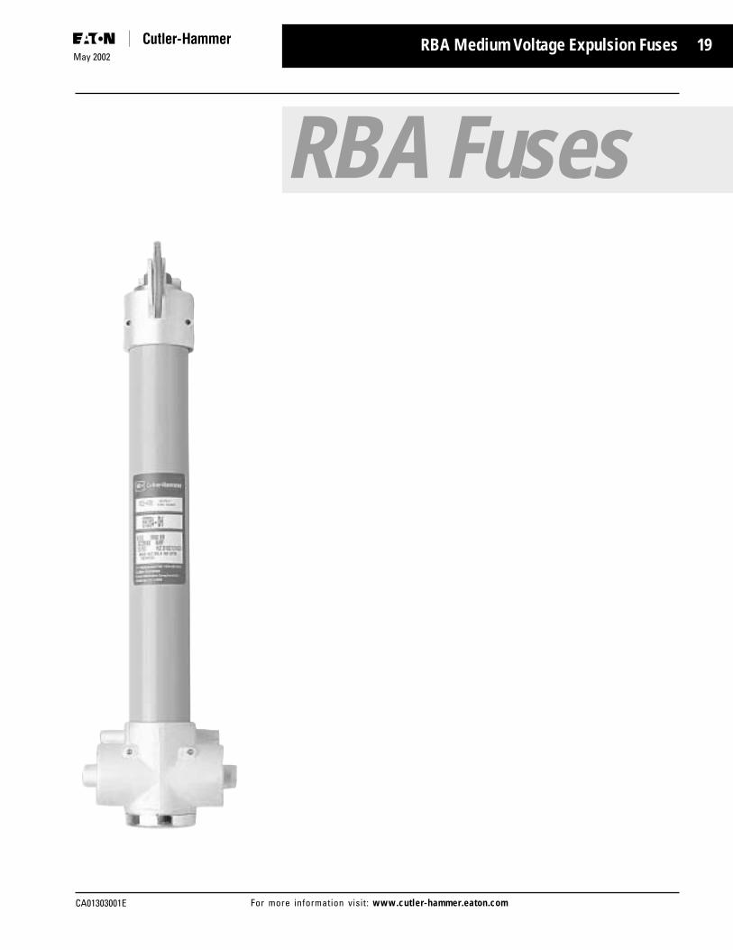
The Cutler-Hammer RBA (RefillableBoric Acid) Power Fuse is a vented,expulsion type power fuse designedfor indoor or weatherproofenclosure applications. The RBA is arenewable (refillable) design. As theword renewable implies, the entirefuse unit is not discarded after itinterrupts a fault. Usually, only oneportion of the fuse, the refill, isreplaced after an interruption. Forthis reason, RBA fuses provide aneconomical approach to theprotection of distribution systemequipment rated up to a maximumof 38 kV. They are especially wellsuited for large industrial loadfusing needs.
An RBA is basically a ventedelectromechanical device designedfor many different powerapplications. The RBA Power Fuseis most effective for higheroperational voltage and highercontinuous current requirements.The RBA expulsion type fuse, notunlike other similar devices, doesnot limit the magnitude of faultcurrent during operation. It limitsthe duration of the fault on theelectrical system.
RBA expulsion fuses are availablein a wide range of ratings tosimplify the selection process. Theyoffer continuous current ratings of1/2 through 720 amperes,maximum voltages of 8.3 through38 kV, and symmetrical interruptingcapabilities of 19,000 through37,500 amperes. In addition, theRBA offers two operating timeconfigurations, standard speed andtime lag (delay). This feature, whencombined with the wide range ofratings, permits customers tomaximize both coordination andprotection.
Since RBA Power Fuses can beused with either disconnect or non-disconnect mountings, fitting thefuse to the equipment type andlayout restrictions is a simplifiedprocess. The RBA is an easy toinstall design and even easier tomaintain.
Applications
In general, an electrical systemconsists of three major parts:generation, transmission anddistribution. The distribution areaoffers an especially significantpotential for RBA Power Fuseapplications. This distributionsystem potential could be with theutility, an industrial or commercialuser, or the manufacturer ofelectrical equipment.
Since the RBA Power Fuse isrefillable (renewable), it iseconomical for use in a variety ofindoor distribution systemapplications. Primarily, the RBA isdesigned for use on:
■ Load Interrupter Switchgear
■ Power Transformers
■ High Voltage Capacitors
■ Pad Mounted Transformers
The RBA can also be installed infuse cabinets for both indoor andoutdoor use.
RBA Power Fuses applied in aseries combination with load breakinterrupter switches provide forreliable switching and faultprotection. This type of equipment,commonly referred to as loadinterrupter switchgear, is anintegrated assembly of switches,bus and fuses that are coordinatedelectrically and mechanically foreffective circuit protection.
Another common application forRBA Power fuses is powertransformer protection. Dependingupon the transformer size and/orlocation, the RBA could be used toprovide protection for thetransformer’s primary. Fusesapplied here must be selected so asnot to blow on such things astransformer inrush current whilestill providing protection againstshort circuits.
The RBA can also be used toprotect capacitor banks. Capacitorsrequire protection from faultcurrents which could cause acapacitor to rupture.
Protective equipment is alsoapplied to the primary of padmounted transformers to protectthe upstream system from faultswhich occur in or beyond thetransformer. Selection of the fusetype is dependent on many factorsincluding: user or supplierpreference, cost, and systemcoordination to mention a few. Ifthe required voltage andcontinuous current ratings are highand downstream coordination iscritical, RBA Power Fuses canprovide very effective protection.

22May 2002
CA01303001EFor more information visit: www.cutler-hammer.eaton.com
RBA Features
Operation and Features
In general, a complete renewable(refillable) indoor boric acidexpulsion type fuse unit consists ofthe following major components:
■ Boric Acid Refill
■ Fuse Holder
■ Mounting
■ Optional Discharge Suppressor
The boric acid refill is a part of thefuse unit which is discarded afteran interruption. It contains thefusible element which melts and aboric acid liner which assists withthe interruption.
A boric acid refill is containedinside a tube called the fuse holder.The fuse holder holds the refill andprovides electrical contact betweenthe refill on the inside and the line/load connections on the outside.
Everything required to safely mounta fuse at its point of application isprovided by the mounting. A fusemounting consists of a metal baseto which a number of other itemsare attached, such as insulators andcurrent carrying parts. Mountingsare usually available in non-disconnect and disconnectconfigurations. A non-disconnectmounting permanently mounts thefuse holder containing the refillwith tension type fuse clips orbolted connections until it iscompletely removed. Thedisconnect mounting permits a fuseto be opened, closed or even liftedout of the mounting once it isopened. An insulated stick with ahook on the end of it is used toperform the opening and closingfunctions in a disconnect mounting.This insulated stick is referred to asa hookstick. Thus the frequentlyheard phrase - hookstick operated.
Depending upon the point ofapplication, it is often necessary toattach a discharge suppressor(filter, condenser or muffler) to thefuse unit. This metallic device acts
to retard, to varying degrees, thegases and noise associated with anexpulsion type fuse.
When the fuse element melts insidethe refill, an arc is initiated andelongated. The heat of the arcdecomposes the boric acidproducing water vapor and boricanhydride. These two by-productsextinguish the arc by blastingthrough it and exit from the bottomof the fuse. The gases are usuallyassisted with the interruptionprocess by a spring loadedmechanical device located insidethe fuse holder. In addition to theexhaust produced duringinterruption, a significant amountof noise also results. At this point,the previously mentionedsuppressor is often used to limitthis discharge and noise. What typeof suppressor is installed dependsupon the requirements at the pointof application.
Typical Boric Acid Fuse with Muffler
Typical Boric Acid Fuse Operation

23
CA01303001E
May 2002
For more information visit: www.cutler-hammer.eaton.com
RBA Features
RBA Details
The Cutler-Hammer renewable RBAfuse unit is not totally discardedafter it interrupts a fault. Thismakes the RBA quite economical touse over time. Normally, only thefuse refill is discarded with the RBAdesign.
The RBA Power Fuse providesperformance characteristicsespecially intended for distributionsystem protection up to anoperational voltage of 34.5 kV.Because the RBA is available in awide range of continuous currentratings and time-currentcharacteristics, close fusing can beachieved, maximizing theprotection and overall coordination.The quality and accuracy of theRBA design and manufacturingprocess ensures accurate initial andongoing melting time-currentcharacteristics. The proven RBAPower fuse performs as intended. Itoperates exactly when and how itshould, and does not operate whenit should not operate. This is asubtle but important point.
Each individual RBA fusecomponent, which is part of thetotal fuse package, is discussedindividually. Its makeup and uniquerole in the protection process arealso discussed.
RBA Refill
It is difficult to call one fusecomponent more important thananother component, since allcomponents must be combined in acoordinated package to functionproperly. If such a designation hadto made, however, the refill wouldhave to be called the mostimportant component. The termrenewable is attributed to the refill,since it is the part of the fusepackage that is replaced after aninterruption. This replacementrenews the fuse to its original stateof protective readiness.
An RBA refill is comprised primarilyof a conducting fuse element, anarcing rod, an auxiliary arcing wire,
a strain element, and a solid boricacid liner which assists with theinterruption. One end of the fuseelement is attached to the end capof the refill tube and the other endis brazed to the main arcing rod. Allof these components are containedwithin a separate fiberglass tube.The fiberglass tube has an end capon one end with a blow-out diskwhich permits exhaust to exitduring interruption. The other endof the tube permits one end of thearcing rod, which is threaded, toexit the refill tube. That end of thetube is sealed around the arcing rodwhere it exits from the refill tube.
The calibrated fuse elementdetermines the operational time-current characteristics of the RBAfuse unit. It is sensitive to the heatproduced by the amount of currentflowing. How, when, or if it meltsfor different magnitudes of current
and amounts of time, a particularcurrent magnitude experienced bythe fuse is indicated on the specifictime-current characteristic curve fora particular fuse. RBA fuseelements are available in standardand time-lag configurations. Thestandard element is made of silverand the time-lag of tin.
The heavy copper cylindrical arcingrod is contained within the mainbore of the boric acid liner andperforms two functions. Undernormal operating conditions, itcarries the continuous rated currentof the fuse. When the fuse elementmelts during a fault condition, thearcing rod draws and lengthens thearc as it moves back into the boricacid liner. This backward movementis made possible because thearcing rod is under spring tensionfrom the outside of the refill. Thedevice causing the spring tensionwill be covered next in the RBAholder discussion.
A nichrome wire, called the strainelement, parallels the fuse elementand relieves the fuse element ofany strain put on it by the springloaded arcing rod. This highresistance wire shunts the fuseelement and vaporizes immediatelyafter the fuse element melts.
An auxiliary arcing wire iscontained within the small bore ofthe boric acid liner. It plays a role inthe proper operation of the fuseunder all fault conditions. No loadcurrent is carried by the auxiliarywire.
RBA Refill Operation
Under fault conditions, the fuseelement melts, the strain elementmelts, the arcing rod and arc arepulled back through the boric acidcylinder. Intense heat from the arcdecomposes the dry boric acid. Ondecomposition, the boric acid formswater vapor and inert boricanhydride which extinguishes thearc by blasting through it and de-ionizing the arc. The exhaustcaused by the interruption exitsfrom the bottom of the fuse

24May 2002
CA01303001EFor more information visit: www.cutler-hammer.eaton.com
RBA Features
through the blow-out disk. Thisprevents the arc from re-strikingafter a current zero.
RBA refills are designed to interruptshort circuit currents within 1/2cycle at current zero. Two differentchambers in parallel within thesolid boric acid liner provide forselective operation and interruptionfor both low current and highcurrent faults utilizing the principlesof De-Ionization.
Low Current Fault Operation
When a low current fault occurs,the main fuse and strain elementsblow. The auxiliary wire shorts outthe main fuse and the arc isextinguished in the small bore ofthe boric acid liner. The arcing rod,drawing no arc, moves back to anopen position because of the springtension.
High Current Fault Operation
A high fault current blows the mainfuse and strain element andtransfers to the auxiliary fuse wire.In the small bore, the arc creates ahigh voltage so it restrikes in themain bore. The arcing rod thendraws the arc through the mainbore where it is quicklyextinguished.
RBA Refill Ratings
RBA fuse refills are ANSI/IEEE “E”rated. The “E” rating is a currentresponse definition that wasintended to produce a degree ofelectrical interchangeability amongfuse manufacturers. Rather thanhaving just a pure current rating fora fuse, the refill has its ampererating stated in terms of a numberfollowed by the capital letter E,100E for example. A 100E fusecarries 100 amperes or belowcontinuously and will melt in adefined amount of time for adefined range of current above thefuse’s continuous currentmagnitude. This performancewould be the same for allmanufacturers with the “E”designation.
Plug
Spring Attaches Here
Blow-Out Disk
Non-ExpellableDry BoricAcid Blocks
Strain Element
Fuse Element
Gasket
FilamentWound Glass
Epoxy Tube
Washer
Auxiliary Bore
Auxililary Wire
Inner Contact
End Cap
Chamber
Arcing Rod
Pin

25
CA01303001E
May 2002
For more information visit: www.cutler-hammer.eaton.com
RBA Features
RBA Holder
An RBA fuse holder is a glass epoxytube which encloses and supportsthe fuse refill. It also includes aspring and shunt assembly,provides for electrical connections,and includes the required hardwarefor use with a non-disconnect or adisconnect mounting. The holderdelivers excellent dielectric strengthas well as mechanical strength forsupport purposes. The RBA holderis not suitable for use in outdoorapplications.
After a fuse unit performs itsfunction by operating, the fuseholder is removed from themounting, opened, and only thefuse refill is replaced. The fuse unitcan then be once again put backinto operation.
Spring and Shunt Assembly
A spring and shunt assembly iscomprised of a helical spring whichencloses a flexible, braided copperwire called the shunt. Thisassembly attaches on one end tothe threaded end of the refill justdiscussed, and on the other end tothe top contact of the holder. Oncethe spring and shunt assembly areproperly attached and enclosed inthe holder, the refill’s arcing rod isput under spring tension and readyto operate by providing therequired force to move the rodinside the refill up into the boricacid liner.
The flexible wire shunt inside thespring is an excellent conductorthat completes the current pathbetween the arcing rod and the topcontact of the holder. Shunting orbypassing the helical shaped springso the spring does not have to carrycurrent requires the wire shunt tobe very flexible. This flexibility isrequired to avoid any entanglementbetween the wire shunt and thespring which could impedemovement of the arcing rod being
pulled by the spring duringoperation.
Holder Contacts and Hardware
The upper and lower contacts of thefuse holder provide the means formaking electrical connectionsbetween the fuse refill and themounting. They are often referredto as end fittings, since they attachto each end of the fuse holder. Thehardware is made of silver platedcast bronze ensuring good electricalcontact between the mounting andfuse itself. In addition, the electricalcontacts also function to dissipateheat while the fuse is conductingelectricity.
The only difference between non-disconnect and disconnect typefuse holders is the type of electricalcontacts attached to the fuseholder. Disconnect electricalhardware permits the fuse to behookstick-operated in a compatibledisconnect type mounting. Ahookeye is provided at each end ofthe fuse holder’s disconnecthardware to accommodate thehook end of a hookstick openingand removal device. Non-disconnect electrical hardwarerequires the fuse unit to be held ina permanent position untilcompletely removed from acompatible mounting.
RBA Mountings
Non-disconnect and disconnectmountings are both available for anRBA Power Fuse. A mountingprovides everything necessary tosafely mount a compatible RBAfuse unit to or in the applicableequipment. The mounting base isthe metal support to which all themounting parts attach. Porcelain orglass polyester insulators areattached to the base and insulatethe live fuse unit and any other livepart from the mounting base andeverything beyond the base. Liveparts, which are attached to theinsulators, hold the fuse unit inplace in the mounting, provide aplace to make line and loadconnections, and are hot onceelectricity is flowing.
Live parts are available without theinsulators or mounting base. Someapplications have unique mountingsituations or the customer may justchoose to add additional value bysupplying the insulators and base.It is still necessary to mount the liveparts in a manner similar to thatused with complete mountings. It isthe customer’s responsibility tomake sure that all mountingrequirements are met when usingjust the live parts.

26May 2002
CA01303001EFor more information visit: www.cutler-hammer.eaton.com
RBA Features
RBA non-disconnect mountings canbe supplied in one of twoconfigurations. RBA 200 and RBA400 mountings use upper and lowerfuse clips to hold the fuse unit inposition under tension. The clipssecurely attach to both ends of thefuse holder. RBA 800 mountingshold the fuse unit in place bysolidly bolting it into position. Thetype of non-disconnect mounting tobe used depends upon the size andconfiguration of the fuse unit.
The RBA disconnect mounting ishookstick-operable which simplifiesopening, closing, and fusereplacement. Not only is thehookstick used to open the fuse, itis used to lift the fuse from itsmounting. This keeps the operatorwell clear of any live parts duringfuse removal. One end of themounting is the hinged end andone is the latched end. They work inconjunction with compatibledisconnect parts attached to thefuse holder. Positive electricalconnections are maintained at bothends of the mounting through theuse of cadmium chromium copperspring fingers at the hinge end andclip type contacts on the break(latch) end. The spring fingers arecompressed on closing in of thefuse holder. The current path isthen made directly from theterminal pad to the fingers and thefuse holder. This upper end of thefuse holder is locked into positionin the fuse holder by a stainlesssteel latch.
RBA Accessories
Optional accessory devices areoften used with indoor expulsionfuses, like the RBA, to retard thegases and noise associated withthis type of fuse during operation.Cutler-Hammer offers two devicescalled the condenser and thedischarge filter. Othermanufacturers might refer to suchdevices as suppressors or silencers.All of these devices act to retard, invarying degrees, the by-products ofan interruption, much the same asan automobile muffler restricts the
by-products of internal combustion.
In cases where installationclearances are small, a condenseror a discharge filter can bethreaded to the bottom of an RBAfuse holder to minimize the noiseand exhaust while containing thearc within the fuse duringinterruption. Both devices aremetallic containers with copperscreen inside to absorb anddissipate arc heat and to condensesteam to water. Although the innerand outer metals of the condenserand discharge filter are similar, theinternal designs and ventingmethods are different.
The condenser’s design fullyrestricts the expulsion process,which requires the interruptingrating (kA) of the fuse to be reducedwhen it is used with the RBA. Useof the discharge filter does notrestrict the expulsion processenough to affect the interruptingrating of the fuse. A view of thebottom of both devices wouldeasily identify which was thecondenser and which was thedischarge filter. The bottom end ofthe condenser is almost totallyclosed with one small weep hole forthe release of water. On the otherhand, the discharge filter has anumber of larger holes. Theapplication and installation locationusually determines which device isselected.
Condenser Discharge Filter

27
CA01303001E
May 2002
For more information visit: www.cutler-hammer.eaton.com
RBA Features
RBA Interruption andProtection
Up to this point, discussions haveconcentrated on the individualitems that make up an RBA PowerFuse unit. Now the discussion willcenter around the complete RBAPower Fuse unit.
Together, the individualcomponents discussed comprise acomplete indoor RBA Power Fuseunit which provides effectiveprotection for circuits andequipment which operate onvoltages from 2400 through 34,500volts.
The RBA Power Fuse has a longand enviable reputation foroutstanding protection andreliability, broad selectionpossibilities, ease of installationand economy over time. At thispoint, it would be beneficial tobriefly review the overall operationof an entire RBA Power Fuse unit.
An RBA Power Fuse unit, whenmounted in a non-disconnect ordisconnect mounting at its point ofapplication, is positioned toperform its protective function ascurrent flows through themounting’s line and loadconnectors. The RBA fuse holdermakes the electrical connectionwith the mounting through itsmounting hardware on each end ofthe holder. The holder’s flexibleshunt provides a current path to therefill which is enclosed by theholder. A spring loaded arcing rod,attached to the flexible shunt,carries the normal continuouscurrent through the refill, and thecircuit is operational. Under normalconditions, the fusible element’stemperature rise is below itsmelting temperature and does notmelt. When a fault occurs that islarge enough to melt the fuseelement inside the refill, an arc isinitiated and elongated by theholder’s helical spring pulling thearcing rod up into the boric acidinterrupting media. The heatproduced decomposes the boric
acid liner inside the refill producingwater vapor and boric anhydridewhich helps to de-ionize the arc.These by-products extinguish thearc at a natural current zero byblasting through it and exiting outthe bottom of the fuse. The exhaustand noise produced during theinterruption process are limited bya condenser or discharge filterattached to the bottom of theholder. The RBA fuse unit, in mostinstances, is put back into operationafter an interruption by removingthe fuse unit from its mounting,replacing the refill inside the holder,and putting the fuse unit back intoits mounting. Although the entireprocess is a bit more involved thanjust described, this should providea general understanding of how theRBA Power Fuse works to provideoutstanding and economicalprotection with limited down time.
During the interrupting process,current continues to flow in thecircuit and in the fuse until acurrent zero is reached. When thearc is stopped at current zero, thevoltage will do its best to reignitethe arc. The voltage across the fuseterminals builds dramatically and isreferred to as the transient recoveryvoltage (TRV). The TRV is the mostsevere waveform the fuse will haveto withstand. This voltage build upputs a great deal of potentiallydestructive stress on the fuse unitand the system itself. Whether ornot extinguishing of the arc issuccessful depends, in general, onthe dielectric strength between thefuse terminals. In short, thedielectric strength between the fuseterminals must be greater than thevoltage trying to reignite the arc fora successful interruption to occur.When properly applied, an RBAPower Fuse has a dielectricrecovery that is more than a matchfor the TRV, regardless of the faultcurrent
The maximum voltage rating of theRBA Power Fuse is the highest rmsvoltage at which the fuse isdesigned to operate. Its dielectricwithstand level corresponds to
insulation levels of power classequipment, thus the name powerfuse. Maximum voltage ratings forRBA Power Fuses are: 8.3, 15.5,25.5 and 38.0 kV.
No fuse, including the RBA PowerFuse, should ever be applied wherethe available fault current exceedsthe interrupting rating of the fuse.The rated interrupting capacity ofthe RBA is the rms value of thesymmetrical component (ACcomponent) of the highest currentwhich the RBA is able tosuccessfully interrupt under anycondition of asymmetry. In short,the interrupting rating must beequal to or greater than themaximum symmetrical fault currentat the point where the fuse isapplied. The RBA has interruptingcapabilities from 19,000 through37,500 amperes symmetrical.
The continuous current rating of anRBA Power Fuse should equal orexceed the maximum load currentwhere the fuse is applied. They aredesigned to carry their ratedcontinuous current withoutexceeding the temperature riseoutlined in NEMA and ANSIstandards.
The RBA is available withcontinuous current ratings up to720 amperes. The current ratingscarry an “E” designation previouslydiscussed and defined by ANSI andNEMA. For example, the currentresponsive element rated 100Eamperes or below shall melt in 300seconds at an rms current withinthe range of 200 to 240 percent ofthe continuous current rating.Above 100E amperes, melting takesplace in 600 seconds at an rmscurrent within the range of 220 to264 percent of the continuouscurrent rating.

28May 2002
CA01303001EFor more information visit: www.cutler-hammer.eaton.com
RBA Features
Coordination considerations mustbe made to help determine whattype of fuse is applied. The RBAPower Fuse interrupts at a naturalcurrent zero in the current waveand allows a minimum of a halfcycle of fault current to flow before
the fault is cleared. The time-current characteristic associatedwith an RBA has a rather gradualslope making it easier to coordinatewith downstream equipment. Inaddition, the RBA is ideal for highervoltage (through 38 kV) and highercurrent applications (through 720amperes). Besides the voltage,interrupting current and continuouscurrent considerations, it isimportant to examine the minimummelting and total clearing time-current characteristics of theparticular fuse.
The melting time is the time inseconds required to melt the fuseelement. This curve indicates whenor even if the element of the fusewill melt for different symmetricalcurrent magnitudes.
The total clearing time is the totalamount of time it takes to clear afault once the element has melted.The total clearing time is really thesum of the melting time and thetime the fuse arcs during theclearing process.
The RBA Power Fuse is offered intwo configurations for use withhigh currents: standard (fast) andtime-lag (slow). The curves for thetime-lag fuse are less inverse andallow for more of a time delay athigh currents.
Finally, low currents, usuallyreferred to as overload currents,must also be considered. The RBAand other expulsion fuses have arather low thermal capacity andcannot carry overloads of the samemagnitude and duration as motorsand transformers of equalcontinuous currents. For this reasonthe fuse must be sized with the fullload current in mind. Thisconsideration should be made sothe fuse does not blow onotherwise acceptable overloads andinrush conditions.
The Cutler-Hammer RBA family ofpower fuses is broad andcomprehensive. Refer to the RBARatings Chart to review the ratingsavailable for most conceivableapplication requirements. Keep inmind that the final selectionprocess includes the selection of arefill, a holder, a mounting and anyrequired accessories.
Load Current in Percent of Fuse Ampere Rating
Mel
ting
Tim
e in
Per
cent
of T
ime
Show
n on
Tim
e -
Curr
ent C
hara
cter
istic
Cur
ve
Fuses Above 100 Amps
P
Fuses 100 Amps and Less
F
100
50
050 100 150 200 2500
Hours
4
3
2
1
1/2
Seconds1000
600
300
100
1 2 3
100% of Fuse Rating
AverageMelting Curves
Above 100 Amps
100 Amps or Less
6

29
CA01303001E
May 2002
For more information visit: www.cutler-hammer.eaton.com
RBA Rating and Selection Information
RBA 200 - with Discharge Filter
Maximum Design Voltage 8.3kV 15.5kV 25.5kV 38kV
Nominal Voltage 2.4kV 4.8kV 7.2kV 13.8kV 14.4kV 23.0kV 34.5kVSymmetrical 19000A 19000A 16600A 14400A 14400A 10500A 6900AAsymmetrical 30000A 30000A 26500A 23000A 23000A 16800A 11000AMaximum X/R Ratio 15 15 15 15 15 15 15Continuous Current-Std Speed 10 to 200A 10 to 200A 10 to 200A 10 to 200A 10 to 200A 10 to 200A 10 to 200AContinuous Current-Time Lag 20 to 200A 10 to 200A 20 to 200A 20 to 200A 20 to 200A 20 to 200A 20 to 200A
RBA 200 - with Condenser
Maximum Design Voltage 8.3kV 15.5kV 25.5kV 38kV
Nominal Voltage 2.4kV 4.8kV 7.2kV 13.8kV 14.4kV 23.0kV 34.5kVSymmetrical 10000A 10000A 10000A 8000A 8000A 6300A 5000AAsymmetrical 16000A 16000A 16000A 12800A 12800A 10100A 8000AMaximum X/R Ratio 15 15 15 15 15 15 15Continuous Current-Std Speed 10 to 200A 10 to 200A 10 to 200A 10 to 200A 10 to 200A 10 to 200A 10 to 200AContinuous Current-Time Lag 20 to 200A 20 to 200A 20 to 200A 20 to 200A 20 to 200A 20 to 200A 20 to 200A
RBA 400 / RBA 800 - with Discharge Filter
Maximum Design Voltage 8.3kV 15.5kV 25.5kV 38kV
Nominal Voltage 2.4kV 4.8kV 7.2kV 13.8kV 14.4kV 23.0kV 34.5kVSymmetrical 37500A 37500A 29400A 29400A 29400A 21000A 16800AAsymmetrical 60000A 60000A 47000A 47000A 47000A 33500A 26800AMaximum X/R Ratio 15 15 15 15 15 15 15Continuous Current-Std Speed RBA 400 1/2 to 400A 1/2 to 400A 1/2 to 400A 1/2 to 400A 1/2 to 400A 1/2 to 400A 1/2 to 400AContinuous Current-Time Lag RBA 400 20 to 400A 20 to 400A 20 to 400A 20 to 400A 20 to 400A 20 to 400A 20 to 400AContinuous Current-Std & Time Lag RBA 800 450 to 720A 450 to 720A 450 to 720A 450 to 720A 450 to 720A 450 to 720A 450 to 720A
RBA 400 / RBA 800 - with Condenser
Maximum Design Voltage 8.3kV 15.5kV 25.5kV 38kV
Nominal Voltage 2.4kV 4.8kV 7.2kV 13.8kV 14.4kV 23.0kV 34.5kVSymmetrical 20000A 20000A 16000A 12500A 12500A 10000A 10000AAsymmetrical 32000A 32000A 25600A 20000A 20000A 16000A 16000AMaximum X/R Ratio 15 15 15 15 15 15 15Continuous Current-Std Speed RBA 400 1/2 to 400A 1/2 to 400A 1/2 to 400A 1/2 to 400A 1/2 to 400A 1/2 to 400A 1/2 to 400AContinuous Current-Time Lag RBA 400 20 to 400A 20 to 400A 20 to 400A 20 to 400A 20 to 400A 20 to 400A 20 to 400AContinuous Current-Time Lag RBA 800 450 to 720A 450 to 720A 450 to 720A 450 to 720A 450 to 720A 450 to 720A 450 to 720A
RBA Power Fuse Ratings
Ratings and Selection
The primary selection ratings,previously discussed, associatedwith an RBA expulsion type fuseare:
■ Continuous Current Rating
■ Maximum Voltage Rating
■ Maximum Interrupting CurrentRating
Cutler-Hammer RBA Power Fuseshave three continuous currentclasses: 200A, 400A and 800A. Theyare designated the RBA-200, RBA-400 and RBA-800. In addition, theRBA is available with specificstandard time or time lag currentcharacteristics for more precisecoordination.
The RBA-200 series offers currentratings of 10E to 200E. The RBA-400
series offers current ratings of 1/2Eto 400E. Both of these RBA fusesare single barrel fuses. In otherwords, one fuse holder with onefuse refill inside the holder is used.
The RBA-800 series offers currentratings of 450, 540 and 720amperes. It parallels two RBA-400fuses, one fuse on the back of theother, to accomplish the highercontinuous current ratings. Thisconfiguration is often referred to asa double barrel fuse. When twoRBA-400 fuses are in parallel, thetotal continuous current rating isderated by 10 percent. For example,when two 400 ampere fuses areparalleled and the 10 percent factorapplied, the result is the 720amperes available as an RBA-800.
An RBA-800 series fuse is not only adouble barrel fuse utilizing two fuseholders, two fuse refills and two
accessory devices (discharge filteror condenser), it requires a specialmounting capable of holding thislarger and heavier fuse. Themounting is often called apiggyback mounting since it holdstwo fuses that are attached back-to-back.
Each RBA current class is availablein an operational voltage rangefrom 2400 to 34,500 volts, withsymmetrical interrupting ratingsfrom 19,000 to 37,500 amperes.Refer to the RBA Ratings Chart forthe wide range of selectionpossibilities.
Dimensional Details
To determine exact dimensions,phase spacing and minimumclearances, refer to the appropriatedimensional tables and outlinedrawings for the RBA fuse unitsselected.

30May 2002
CA01303001EFor more information visit: www.cutler-hammer.eaton.com
1 Phase-to-phase center spacing, without barriers.
RBA Dimensional Details
RBA Fuse Mountings - RBA 200,400 Disconnect Mountng - 4.8 to 34.5 kV
Dimensions in InchesCatalogNumber kV W Recom-
BIL A B C D E F G H I J K L M N P R mendedWith With PhaseCon- Dis- Spacing
denser charge 1
5RBA2 60 22.62 7.00 7.50 3.50 5.87 14.25 27.19 3.34 18.69 18.81 9.25 1.56 10.12 1.64 1.50 7.50 3.00 7.50 11.50
8RBA2 75 22.62 7.00 10.00 6.00 5.87 14.25 29.69 6.34 18.69 18.81 9.25 1.56 10.12 1.64 1.50 7.50 4.00 8.50 13.00
14RBA2 95 22.62 7.00 10.00 6.00 2.62 17.62 32.12 6.34 22.06 22.19 9.25 1.56 10.12 1.64 1.50 8.75 6.00 11.50 14.50
15RBA2 110 22.62 7.00 11.50 7.50 2.62 17.62 33.62 7.84 22.06 22.19 9.25 1.56 10.12 1.64 1.50 8.75 6.00 11.50 16.00
25RBA2 150 33.88 8.00 12.00 10.50 2.50 22.25 37.69 11.71 26.69 26.81 9.25 1.56 10.12 1.64 1.50 10.50 8.50 15.00 20.00
38RBA2 150 33.88 8.00 12.00 10.50 2.50 29.25 42.62 11.71 33.69 33.81 9.25 1.56 10.12 1.64 1.50 13.12 12.00 19.50 25.00
5RBA4 60 22.25 7.00 7.50 3.50 5.94 13.81 27.40 3.03 19.69 20.00 9.25 2.63 11.75 2.17 2.20 7.62 3.00 7.50 11.75
8RBA4 75 22.25 7.00 10.00 6.00 5.94 13.81 29.90 5.53 19.69 20.00 9.25 2.63 11.75 2.17 2.20 7.62 4.00 8.50 13.25
14RBA4 95 22.25 7.00 10.00 6.00 2.56 17.19 32.81 5.53 23.69 23.38 9.25 2.63 11.75 2.17 2.20 8.88 6.00 11.50 14.75
15RBA4 110 22.25 7.00 11.50 7.50 2.56 17.19 34.31 7.03 23.69 23.38 9.25 2.63 11.75 2.17 2.20 8.88 6.00 11.50 16.25
25RBA4 150 33.81 8.00 13.50 10.50 2.50 21.81 39.56 9.03 27.69 28.00 9.25 2.63 11.75 2.17 2.20 11.38 8.50 15.00 20.25
38RBA4 150 33.81 8.00 13.50 10.50 2.50 28.81 44.50 9.03 34.69 35.00 9.25 2.63 11.75 2.17 2.20 13.62 12.00 19.50 25.25
JN
Fuse Holder
A-20 Insulators Used on 4.8 to 14.4 kVA-30 Insulators Used on 23.0 and 34.5 kV
A
B
.75
.75
.75 .75
.881.75
3.56
3.56
1.75
.62 DIA. HOLES (4)
.56 DIA. HOLES (4)
C KG
I
L
M
H
W - MinimumClearance to Ground
45° OPENING
Fuse Refill
P
R.61
E
F
D

31
CA01303001E
May 2002
For more information visit: www.cutler-hammer.eaton.com
RBA Dimensional Details
RBA-200 RBA-400 and RBA 800 (Piggy Back Type) - Non-Disconnect Mounting 4.8 to 34.5 kV
Dimensions in Inches Catalog kV Number BIL A B C D E F G H J K R W Recom-
2 With With mendedCon- Dis- Phase
denser charge Spacing 2
5RBA2 60 15.62 4.62 11.43 8.62 15.62 7.50 1.32 7.50 18.25 1.64 3.00 7.50 11.168RBA2 75 15.62 7.12 13.93 8.62 15.62 7.50 1.32 7.50 18.25 1.64 4.00 8.50 12.56
14RBA2 95 19.00 7.12 13.93 8.62 19.00 7.50 1.32 7.50 21.63 1.64 6.00 11.50 13.06
15RBA2 110 19.00 8.62 15.43 8.62 19.00 7.50 1.32 7.50 21.63 1.64 6.00 11.50 15.56
25RBA2 150 26.43 12.12 18.93 7.25 29.43 8.50 2.50 8.50 26.25 1.64 8.50 15.00 19.56
38RBA2 150 33.43 12.12 18.93 7.25 36.43 8.50 2.50 8.50 33.25 1.64 12.00 19.50 24.56
5RBA4 60 16.56 4.62 12.31 8.75 16.56 7.50 1.32 7.50 19.52 2.17 3.00 7.50 11.168RBA4 75 16.56 7.12 14.81 8.75 16.56 7.50 1.32 7.50 19.52 2.17 4.00 8.50 12.56
14RBA4 95 19.94 7.12 14.81 8.75 19.94 7.50 1.32 7.50 22.90 2.17 6.00 11.50 13.06
15RBA4 110 19.94 8.62 16.31 8.75 19.94 7.50 2.50 7.50 22.90 2.17 6.00 11.50 15.56
25RBA4 150 27.37 12.12 19.81 7.37 30.37 8.50 1.32 8.50 22.90 2.17 8.50 15.00 19.56
38RBA4 150 34.37 12.12 19.81 7.37 37.37 8.50 2.50 8.50 34.52 2.17 12.00 19.50 24.56
5RBA8 60 16.31 4.50 12.85 9.31 17.56 3.50 1.62 3.50 16.31 2.17 3.00 7.50 11.008RBA8 75 16.31 7.00 15.35 9.31 17.56 6.00 1.62 6.00 16.31 2.17 4.00 8.50 12.50
14RBA8 95 19.81 7.00 15.35 9.31 21.06 6.00 1.62 6.00 19.81 2.17 6.00 11.50 14.00
15RBA8 110 19.81 8.50 16.85 9.31 21.06 7.50 1.62 7.50 19.81 2.17 6.00 11.50 15.50
25RBA8 150 24.50 11.50 19.85 9.31 27.50 10.50 2.50 10.50 24.50 2.17 6.00 15.00 19.50
38RBA8 150 31.50 11.50 19.85 9.31 34.50 10.50 2.50 10.50 31.50 2.17 12.00 19.50 24.50
1 Phase-to-phase center spacing, without barriers.2 Approximate dimensions.
E
H
1.75
1.75
1.00
.62
.62
1.00
4.25.44 DIA.HOLES (8)
A
Fuse Holder RBA-800
G
C
B
D
JR
.66
6.12
6.12
.41 DIA.HOLES (2)
.41 DIA.HOLES (2)
W - MinimumClearance to Ground
Fuse Holder RBA-200,400
A
CB
D5.87
5.87
R
W - MinimumClearance to Ground
K
6.00
F
G
F

32May 2002
CA01303001EFor more information visit: www.cutler-hammer.eaton.com
RBA Testing and Performance
Testing and Performance
■ Standards
■ Testing
■ Quality Standards
Cutler-Hammer does notcompromise when performance,quality and safety are involved.Exacting standards have beenestablished relative to the design,testing and application of expulsiontype power fuses. Compliance withthese standards ensures the bestselection and performance.
Type RBA Power Fuses aredesigned and tested to applicableportions of ANSI standards as wellas other industry standards. TheANSI standards are ConsensusStandards jointly formulated byIEEE and NEMA.
IEEE (Institute of Electrical andElectronic Engineers) is anobjective technical organizationmade up of manufacturers, usersand other general interest parties.NEMA (National ElectricalManufacturers Association) is anelectrical equipment manufacturer-only organization with memberslike Cutler-Hammer. ANSI(American National StandardsInstitute) is a non-profit, privatelyfunded membership organizationthat coordinates the developmentof U.S. voluntary nationalstandards. It is also the U.S.member body to the non-treatyinternational standards bodies,such as International Organizationfor Standardization (ISO) and theInternational ElectrotechnicalCommission (IEC).
The specific standards associatedwith RBA Power Fuses are:
■ ANSI C37.40 - Service Conditionsand Definitions
■ ANSI C37.41 - Power Fuse Designand Testing
■ ANSI C37.46 - Power FuseRatings and Specifications
■ ANSI C37.48 - Power FuseApplication, Operation &Maintenance
Testing
RBA Power Fuse unit design testingwas performed on standardproduction fuses, holders,mountings and accessories.Demanding tests were performed atthe Cutler-Hammer TechnicalCenter and also at recognizedindependent power testinglaboratories. Thermal andinterrupting testing was conductedat 8.3, 15.5, 25.5 and 38kV levels.The entire series of tests wasconducted in a specific sequence asstipulated by governing standardswithout any maintenance beingperformed. All test results areverified by laboratory tabulationsand oscillogram plots.
Quality
Every effort is made to ensure thedelivery of quality fuse units andcustomer satisfaction. All Cutler-Hammer fuses are completelyinspected at each manufacturingstage.
In addition to ongoing qualitycontrol inspections, testing isperformed prior to shipment. AMicro-Ohm Resistance Test isperformed on each fuse to assureproper element construction,alignment and tightness ofelectrical connections. Constructionintegrity testing is also performedon every unit.
Each RBA fuse unit is checked toensure that all items are supplied inkeeping with manufacturingdrawings. Individual fuses arepacked in a plastic bag and then putinto individual cartons. In addition,fuses are overpacked in a shippingcarton to prevent shipping damage.Finally, mountings are packaged inheavy cardboard containers withreinforced wooden bases.

33
CA01303001E
May 2002
For more information visit: www.cutler-hammer.eaton.com
RBA Installation
Installation and Use
■ Receiving
■ Mounting Installation
■ Refill and Discharge SuppressorInstallation
■ Fuse Holder Installation
Receiving
Large orders of fuse mountings andfuses could be shipped securelyattached to a pallet. Although theuse of a forklift to lift a pallet is notrecommended, forklift provisionsare provided. If a forklift is used, theforks must be extended through theskid to avoid damaging theequipment.
During receiving and installation ofthe equipment, care should beexercised so as to prevent damageand insure proper operation.Porcelain mounting insulators, forexample, are quite strong but canbe broken producing sharp edgesthat could compromise theelectrical characteristics of theinsulator.
Inspect each item carefully for anysigns of shipping damage. Check allitems against the manifest toensure that the correct items andquantities are received. Keep inmind that refill instructions and arefill tool are provided with eachfuse unit. Note any shortages ordamage and file a claimimmediately.
If any fuse, mounting or accessoryis not intended for immediate use,it should remain in its originalprotective container and stored in aclean, dry place.
Mounting Installation
RBA disconnect mountings, non-disconnect mountings or othermounting hardware, such as liveparts, should be securely mountedin keeping with instructionsprovided and the requirements ofapplicable standards and localcodes. Good safety practices andelectrical requirements should bestrictly observed to insure a safeand functional installation.
Fuse mountings are completelyassembled and gauged beforeshipment. This helps to simplify theinstallation and ensure correctoperation. Prior to installation,check the mounting and theoperation of its compatible fuseholder in the mounting.
When mounting the base, bolt it tothe supporting structure utilizingthe mounting holes provided. Useshims to prevent base distortionwhen bolting to an uneven surface.Connect conductors to theterminals so that stress is not puton the insulators. Proper torqueshould be maintained for the size ofthe bolts used. Once the mountingis installed, it should be recheckedin the same way it was checkedbefore installation.
If live parts above the insulator arebeing mounted instead of acomplete Cutler-Hammer mounting,it is the customer’s responsibility toverify that the installation meets allelectrical requirements and isinstalled properly.
Refill and Discharge Suppressor
Installation
The Cutler-Hammer RBA PowerFuse is a replaceable design. Afterthe fuse holder has been removedfrom the circuit or before it hasbeen installed in a new installation,a new refill must be installed. Anydischarge suppressors (dischargefilter or condenser) which will beused must also be installed.
Whether installing a fuse refill or adischarge suppressor for the firsttime during an initial installation orreplacing components after aninterruption, the installationprocedures are very similar.Remember a new refill is suppliedcomplete with instructions and arefill tool. The refill tool is threadedat both ends to accommodate RBA-200 and RBA-400 refills.
Simple step-by-step instructions areprovided for removing andreplacing a used refill or installing arefill at a new installation.
Fuse Holder Installation
Since some fuse units can be ratherheavy, especially when equippedwith surge suppressors or of apiggyback configuration, it may beadvisable to have assistance whenremoving or replacing certain fuseunits. This is especially applicableto fuse units in non-disconnect typemountings.
RBA Disconnect: The RBAdisconnect mounting is notintended to be a loadbreak deviceand should not be opened underload. RBA disconnect fuse holdersare designed to be opened orclosed and removed or replacedusing a standard live-line tool. Thehook on the end of the tool isinserted into the hookeye on thelatch end and pulled sharply toopen or pushed sharply to closeand latch. Once in the openposition, the hook is connected tothe hookeye on the hinged end andused to lift the fuse unit upwardand out of its mounting. Similarly,the fuse unit can be placed into itsmounting and closed by reversingthe removal procedure.
RBA Non-Disconnect: Removal orreplacement of an RBA fuse unitusing a non-disconnect mounting isonly performed after it has been de-energized and properly grounded inaccordance with good electricalsafety practices and all applicablelocal procedures.
If the mounting uses tension typemounting clips to hold the fuseunit, pull the fuse unit firmly fromthe clips for removal. Reverse theprocedure to mount a new fuse.
When the mounting uses boltedconnections to hold the fuse unit,unbolt the mounting hardware andcarefully lift the fuse from itsmounting. Reverse the procedure tomount a new fuse.

34May 2002
CA01303001EFor more information visit: www.cutler-hammer.eaton.com
To refill a fuse:
1. Loosen the cap nut with a wrenchand remove it from the top of thefuse holder.
2. Unscrew the discharge filter orcondenser from the bottom of thefuse holder.
3. Remove the spring and shuntassembly. Unscrew and removethe used fuse refill.
4. Remove the thin plastic disc fromthe bottom of the new fuse refillunit. Screw the refill into thebottom of the spring and shuntassembly, and hand tighten. Donot use any type of tool to tightenthe refill. Screw the refill tool intotop of spring and shunt assemblythen slide the complete unit intothe fuse holder.
5. Grasp the refill tool and pullupward to stretch the spring. Turnthe assembly to the right or left toalign the pin at the top of theshunt assembly with the slotprovided at the tip of the fuseholder. Remove the tool and screwthe cap nut on then tighten with awrench.
6. Screw the discharge filter orcondenser into the coupler on thebottom of the fuse holder until it istight against the fuse refill.
Refill Replacement
Cutler-Hammer RBA Power Fuses utilize a replaceable design. After thefuse holder has been removed from the circuit, the fuse can be rechargedby replacement with a new refill unit.
RBA Refill Replacement

35
CA01303001E
May 2002
For more information visit: www.cutler-hammer.eaton.com
RBA Fuse Curves
TIM
E IN
SE
CO
ND
S
100009000800070006000
5000
4000
3000
2000
1000900800700600
500
400
300
200
10090807060
50
40
30
20
109876
5
4
3
2
1.9.8.7.6
.5
.4
.3
.2
.1.09.08.07.06
.05
.04
.03
.02
.01
CURRENT IN AMPERES
1000
0090
000
8000
070
000
6000
0
5000
0
4000
0
3000
0
2000
0
1000
090
0080
0070
0060
00
5000
4000
3000
2000
100090
080
070
060
0
500
400
300
200
100
90807060504030201098765
Curves are based on tests starting with fuse unit at ambient temperature of 25 C and without initial load. Curves are plotted to minimum test points so all variations should be positive.For coordination with another protective device on the load side of the fuse, the melting characteristic of the fuse must be separated from the operating char-acteristic of the other device by an appropriate safety zone.When added at the left side of any melt-ing curve, the safety band shown covers the ordinary service variables including preloading.In the direct comparison of performance charts, placing the RH and LH borders of the chart of the other device on the safety zone limits of this curve sheet is equivalent to adding the safety band to all melting curves.
200E
150E
125E
100E
80E
65E
50E
40E
30E
25E
20E
15E
10E
Type RBA-RDB-200 Refill Power Fuses - Standard Speed Refills CURVE 36-635 # 1Minimum Melting Time-Current Characteristics - 2.4 to 34.5 kV April 1999
Reference # 628823Curves are based on tests starting with fuse unit at ambient temperature of 25°C and without initial load.Curves are plotted to minimum test points so all variations should be positive.

36May 2002
CA01303001EFor more information visit: www.cutler-hammer.eaton.com
RBA Fuse Curves
TIM
E IN
SE
CO
ND
S10000
9000800070006000
5000
4000
3000
2000
1000900800700600
500
400
300
200
10090807060
50
40
30
20
109876
5
4
3
2
1.9.8.7.6
.5
.4
.3
.2
.1.09.08.07.06
.05
.04
.03
.02
.01
CURRENT IN AMPERES
1000
0090
000
8000
070
000
6000
0
5000
0
4000
0
3000
0
2000
0
1000
090
0080
0070
0060
00
5000
4000
3000
2000
100090
080
070
060
0
500
400
300
200
100
90807060504030201098765
200E
150E
125E
100E
80E
65E
50E
40E
30E
25E
20E
15E
10E
Type RBA-RDB-200 Refill Power Fuses - Standard Speed Refills CURVE 36-635 # 2Total Clearing Time-Current Characteristics - 2.4 to 34.5 kV April 1999
Reference # 667014Curves are based on tests starting with fuse unit at ambient temperature of 25 C and without initial load.Curves are plotted to maximum test points so all variations should be negative.

37
CA01303001E
May 2002
For more information visit: www.cutler-hammer.eaton.com
RBA Fuse Curves
TIM
E IN
SE
CO
ND
S
100009000800070006000
5000
4000
3000
2000
1000900800700600
500
400
300
200
10090807060
50
40
30
20
109876
5
4
3
2
1.9.8.7.6
.5
.4
.3
.2
.1.09.08.07.06
.05
.04
.03
.02
.01
CURRENT IN AMPERES
1000
0090
000
8000
070
000
6000
0
5000
0
4000
0
3000
0
2000
0
1000
090
0080
0070
0060
00
5000
4000
3000
2000
100090
080
070
060
0
500
400
300
200
100
90807060504030201098765
Characteristics - 2.4 to 34.5 kVFor coordination withanother protective device on the load side of the fuse, the melting characteristic of the fuse must be separated from the operating characteristic of the other device by an appropriate safety zone.
When added at the left side of any melt-ing curve, the safety band shown covers the ordinary service variables including preloading.
In the direct comparison of performance charts, placing the RH and LH borders of the chart of the other device on the safety zone limits of this curve sheet is equivalent to adding the safety band to all melting curves.
200E
150E
125E
100E
80E
65E
50E
40E
30E
25E
20E
Type RBA-RDB-200 Refill Power Fuses - Time Lag Refills CURVE 36-635 # 3Minimum Melting Time-Current Characteristics - 2.4 to 34.5 kV April 1999
Reference # 628863Curves are based on tests starting with fuse unit at ambient temperature of 25°C and without initial load.Curves are plotted to minimum test points so all variations should be positive.

38May 2002
CA01303001EFor more information visit: www.cutler-hammer.eaton.com
RBA Fuse Curves
TIM
E IN
SE
CO
ND
S10000
9000800070006000
5000
4000
3000
2000
1000900800700600
500
400
300
200
10090807060
50
40
30
20
109876
5
4
3
2
1.9.8.7.6
.5
.4
.3
.2
.1.09.08.07.06
.05
.04
.03
.02
.01
CURRENT IN AMPERES
1000
0090
000
8000
070
000
6000
0
5000
0
4000
0
3000
0
2000
0
1000
090
0080
0070
0060
00
5000
4000
3000
2000
100090
080
070
060
0
500
400
300
200
100
90807060504030201098765
200E
150E
125E
100E
80E
65E
50E
40E
30E
25E
20E
Type RBA-RDB-200 Refill Power Fuses - Time Lag Refills CURVE 36-635 # 4Total Clearing Time-Current Characteristics - 2.4 to 34.5 kV April 1999
Reference # 667013Curves are based on tests starting with fuse unit at ambient temperature of 25 C and without initial load.Curves are plotted to maximum test points so all variations should be negative.

39
CA01303001E
May 2002
For more information visit: www.cutler-hammer.eaton.com
RBA Fuse Curves
TIM
E IN
SE
CO
ND
S
100009000800070006000
5000
4000
3000
2000
1000900800700600
500
400
300
200
10090807060
50
40
30
20
109876
5
4
3
2
1.9.8.7.6
.5
.4
.3
.2
.1.09.08.07.06
.05
.04
.03
.02
.01
CURRENT IN AMPERES
1000
0090
000
8000
070
000
6000
0
5000
0
4000
0
3000
0
2000
0
1000
090
0080
0070
0060
00
5000
4000
3000
2000
100090
080
070
060
0
500
400
300
200
100
90807060504030201098765
Characteristics - 2.4 to 34.5 kVFor coordination with another protective device on the load side of the fuse, the melting characteristic of the fuse must be separated from the operating characteristic of the other device by an appropriate safety zone.
When added at the left side of any melt-ing curve, the safety band shown covers the ordinary service variables including preloading.
In the direct comparison of performance charts, placing the RH and LH borders of the chart of the other device on the safety zone limits of this curve sheet is equivalent to adding the safety band to all melting curves.
3E
150E
200E
250E
300E
400E
125E
100E
80E
65E
50E
40E
30E
25E
20E
15E
10E
7E
5E
Type RBA-RDB-400 Refill Power Fuses - Standard Speed Refills CURVE 36-635 # 5Minimum Melting Time-Current Characteristics - 2.4 to 34.5 kV April 1999
Reference # 628861Curves are based on tests starting with fuse unit at ambient temperature of 25°C and without initial load.Curves are plotted to minimum test points so all variations should be positive.
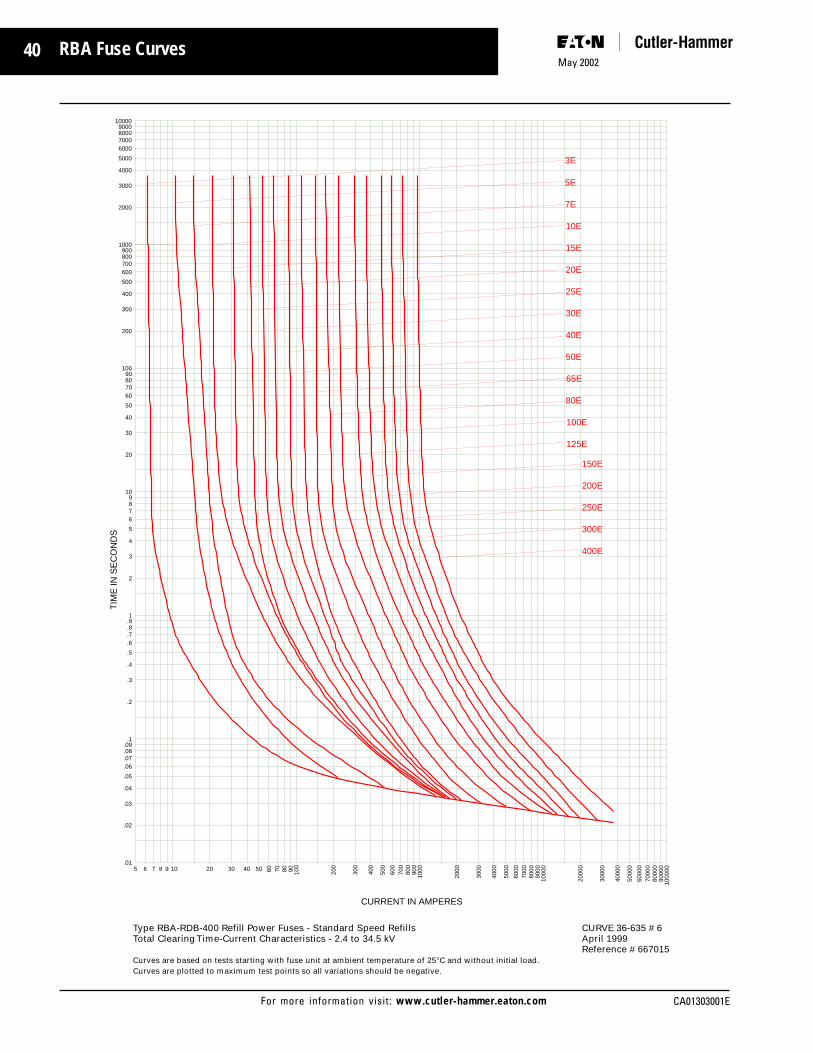
40May 2002
CA01303001EFor more information visit: www.cutler-hammer.eaton.com
RBA Fuse Curves
TIM
E IN
SE
CO
ND
S10000
9000800070006000
5000
4000
3000
2000
1000900800700600
500
400
300
200
10090807060
50
40
30
20
109876
5
4
3
2
1.9.8.7.6
.5
.4
.3
.2
.1.09.08.07.06
.05
.04
.03
.02
.01
CURRENT IN AMPERES
1000
0090
000
8000
070
000
6000
0
5000
0
4000
0
3000
0
2000
0
1000
090
0080
0070
0060
00
5000
4000
3000
2000
100090
080
070
060
0
500
400
300
200
100
90807060504030201098765
3E
150E
200E
250E
300E
400E
125E
100E
80E
65E
50E
40E
30E
25E
20E
15E
10E
7E
5E
Type RBA-RDB-400 Refill Power Fuses - Standard Speed Refills CURVE 36-635 # 6Total Clearing Time-Current Characteristics - 2.4 to 34.5 kV April 1999
Reference # 667015Curves are based on tests starting with fuse unit at ambient temperature of 25°C and without initial load.Curves are plotted to maximum test points so all variations should be negative.

41
CA01303001E
May 2002
For more information visit: www.cutler-hammer.eaton.com
RBA Fuse Curves
TIM
E IN
SE
CO
ND
S
100009000800070006000
5000
4000
3000
2000
1000900800700600
500
400
300
200
10090807060
50
40
30
20
109876
5
4
3
2
1.9.8.7.6
.5
.4
.3
.2
.1.09.08.07.06
.05
.04
.03
.02
.01
CURRENT IN AMPERES
1000
0090
000
8000
070
000
6000
0
5000
0
4000
0
3000
0
2000
0
1000
090
0080
0070
0060
00
5000
4000
3000
2000
100090
080
070
060
0
500
400
300
200
100
90807060504030201098765
Curves are based on tests starting with fuse unit at ambient temperature of 25 C and without initial load. Curves are plotted to minimum test points so all variations should be positive.For coordination with another protective device on the load side of the fuse, the melting characteristic of the fuse must be separated from the operating characteristic of the other device by an appropriate safety zone.
When added at the left side of any melt-ing curve, the safety band shown covers the ordinary service variables including preloading.
In the direct comparison of performance charts, placing the RH and LH borders of the chart of the other device on the safety zone limits of this curve sheet is equivalent to adding the safety band to all melting curves.
150E
200E
125E
100E
80E
65E
50E
40E
30E
25E
20E
Type RBA-RDB-400 Refill Power Fuses - Time Lag Refills CURVE 36-635 # 7Minimum Melting Time-Current Characteristics - 2.4 to 34.5 kV April 1999
Reference # 628865Curves are based on tests starting with fuse unit at ambient temperature of 25°C and without initial load.Curves are plotted to minimum test points so all variations should be positive.
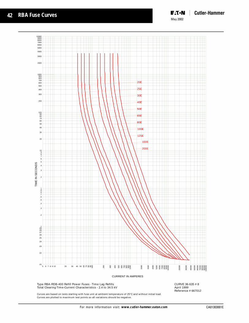
42May 2002
CA01303001EFor more information visit: www.cutler-hammer.eaton.com
RBA Fuse Curves
TIM
E IN
SE
CO
ND
S10000
9000800070006000
5000
4000
3000
2000
1000900800700600
500
400
300
200
10090807060
50
40
30
20
109876
5
4
3
2
1.9.8.7.6
.5
.4
.3
.2
.1.09.08.07.06
.05
.04
.03
.02
.01
CURRENT IN AMPERES
1000
0090
000
8000
070
000
6000
0
5000
0
4000
0
3000
0
2000
0
1000
090
0080
0070
0060
00
5000
4000
3000
2000
100090
080
070
060
0
500
400
300
200
100
90807060504030201098765
150E
200E
125E
100E
80E
65E
50E
40E
30E
25E
20E
Type RBA-RDB-400 Refill Power Fuses - Time Lag Refills CURVE 36-635 # 8Total Clearing Time-Current Characteristics - 2.4 to 34.5 kV April 1999
Reference # 667012Curves are based on tests starting with fuse unit at ambient temperature of 25°C and without initial load.Curves are plotted to maximum test points so all variations should be negative.

43
CA01303001E
May 2002
For more information visit: www.cutler-hammer.eaton.com
RBA Fuse Curves
TIM
E IN
SE
CO
ND
S
100009000800070006000
5000
4000
3000
2000
1000900800700600
500
400
300
200
10090807060
50
40
30
20
109876
5
4
3
2
1.9.8.7.6
.5
.4
.3
.2
.1.09.08.07.06
.05
.04
.03
.02
.01
CURRENT IN AMPERES
1000
0090
000
8000
070
000
6000
0
5000
0
4000
0
3000
0
2000
0
1000
090
0080
0070
0060
00
5000
4000
3000
2000
100090
080
070
060
0
500
400
300
200
100
90807060504030201098765
400E
300E
250E
Type RBA-RDB-400 Refill Power Fuses - Time Lag Refills CURVE 36-635 # 9Minimum Melting Time-Current Characteristics - 2.4 to 34.5 kV April 1999
Reference # 639435Curves are based on tests starting with fuse unit at ambient temperature of 25°C and without initial load.Curves are plotted to minimum test points so all variations should be positive.

44May 2002
CA01303001EFor more information visit: www.cutler-hammer.eaton.com
RBA Fuse Curves
TIM
E IN
SE
CO
ND
S10000
9000800070006000
5000
4000
3000
2000
1000900800700600
500
400
300
200
10090807060
50
40
30
20
109876
5
4
3
2
1.9.8.7.6
.5
.4
.3
.2
.1.09.08.07.06
.05
.04
.03
.02
.01
CURRENT IN AMPERES
1000
0090
000
8000
070
000
6000
0
5000
0
4000
0
3000
0
2000
0
1000
090
0080
0070
0060
00
5000
4000
3000
2000
100090
080
070
060
0
500
400
300
200
100
90807060504030201098765
400E
300E
250E
Type RBA-RDB-400 Refill Power Fuses - Time Lag Refills CURVE 36-635 # 10Total Clearing Time-Current Characteristics - 2.4 to 34.5 kV April 1999
Reference # 667011Curves are based on tests starting with fuse unit at ambient temperature of 25°C and without initial load.Curves are plotted to maximum test points so all variations should be negative.

45
CA01303001E
May 2002
For more information visit: www.cutler-hammer.eaton.com
RBA Fuse Curves
TIM
E IN
SE
CO
ND
S
100009000800070006000
5000
4000
3000
2000
1000900800700600
500
400
300
200
10090807060
50
40
30
20
109876
5
4
3
2
1.9.8.7.6
.5
.4
.3
.2
.1.09.08.07.06
.05
.04
.03
.02
.01
CURRENT IN AMPERES
1000
0090
000
8000
070
000
6000
0
5000
0
4000
0
3000
0
2000
0
1000
090
0080
0070
0060
00
5000
4000
3000
2000
100090
080
070
060
0
500
400
300
200
100
90807060504030201098765
2 x 400E
2 x 300E
2 x 250E
Type RBA-RDB-800 Refill Power Fuses - Standard Speed Refills CURVE 36-635 # 11Minimum Melting Time-Current Characteristics - 2.4 to 34.5 kV April 1999
Reference # 628861Curves are based on tests starting with fuse unit at ambient temperature of 25°C and without initial load.Curves are plotted to minimum test points so all variations should be positive.

46May 2002
CA01303001EFor more information visit: www.cutler-hammer.eaton.com
RBA Fuse Curves
TIM
E IN
SE
CO
ND
S10000
9000800070006000
5000
4000
3000
2000
1000900800700600
500
400
300
200
10090807060
50
40
30
20
109876
5
4
3
2
1.9.8.7.6
.5
.4
.3
.2
.1.09.08.07.06
.05
.04
.03
.02
.01
CURRENT IN AMPERES
1000
0090
000
8000
070
000
6000
0
5000
0
4000
0
3000
0
2000
0
1000
090
0080
0070
0060
00
5000
4000
3000
2000
100090
080
070
060
0
500
400
300
200
100
90807060504030201098765
2 x 400E
2 x 300E
2 x 250E
Type RBA-RDB-800 Refill Power Fuses - Standard Speed Refills CURVE 36-635 # 12Total Clearing Time-Current Characteristics - 2.4 to 34.5 kV April 1999
Reference # 667010Curves are based on tests starting with fuse unit at ambient temperature of 25°C and without initial load.Curves are plotted to maximum test points so all variations should be negative.

47
CA01303001E
May 2002
For more information visit: www.cutler-hammer.eaton.com
RBA Fuse Curves
TIM
E IN
SE
CO
ND
S
100009000800070006000
5000
4000
3000
2000
1000900800700600
500
400
300
200
10090807060
50
40
30
20
109876
5
4
3
2
1.9.8.7.6
.5
.4
.3
.2
.1.09.08.07.06
.05
.04
.03
.02
.01
CURRENT IN AMPERES
1000
0090
000
8000
070
000
6000
0
5000
0
4000
0
3000
0
2000
0
1000
090
0080
0070
0060
00
5000
4000
3000
2000
100090
080
070
060
0
500
400
300
200
100
90807060504030201098765
2 x 400E
2 x 300E
2 x 250E
Type RBA-RDB-800 Refill Power Fuses - Time Lag Refills CURVE 36-635 # 13Minimum Melting Time-Current Characteristics - 2.4 to 34.5 kV April 1999
Reference # 639435Curves are based on tests starting with fuse unit at ambient temperature of 25°C and without initial load.Curves are plotted to minimum test points so all variations should be positive.

48May 2002
CA01303001EFor more information visit: www.cutler-hammer.eaton.com
RBA Fuse Curves
TIM
E IN
SE
CO
ND
S10000
9000800070006000
5000
4000
3000
2000
1000900800700600
500
400
300
200
10090807060
50
40
30
20
109876
5
4
3
2
1.9.8.7.6
.5
.4
.3
.2
.1.09.08.07.06
.05
.04
.03
.02
.01
CURRENT IN AMPERES
1000
0090
000
8000
070
000
6000
0
5000
0
4000
0
3000
0
2000
0
1000
090
0080
0070
0060
00
5000
4000
3000
2000
100090
080
070
060
0
500
400
300
200
100
90807060504030201098765
2 x 400E
2 x 300E
2 x 250E
Type RBA-RDB-800 Refill Power Fuses - Time Lag Refills CURVE 36-635 # 14Total Clearing Time-Current Characteristics - 2.4 to 34.5 kV April 1999
Reference # 667009Curves are based on tests starting with fuse unit at ambient temperature of 25°C and without initial load.Curves are plotted to maximum test points so all variations should be negative.

49
CA01303001E
May 2002
For more information visit: www.cutler-hammer.eaton.com
RBA Catalog Numbers and Information
Type RBA Expulsion Fuses for Use Indoors or in an Enclosure
Am
pere
Rat
ing
Curv
e Re
fere
nce
36-6
35
Curv
e Re
fere
nce
36-6
35
Cata
log
Num
ber
Cata
log
Num
ber
Standard Speed(Fuse Refills)
Time-Lag(Fuse Refills)
Cata
log
Num
ber
Cata
log
Num
ber
Fuseholder Voltage (kV)
Cata
log
Num
ber
Cata
log
Num
ber
Cata
log
Num
ber
Cata
log
Num
ber
Mounting (includingLive Parts less Holder)
Live Parts Fuse Filtersand
Condensers
Spring andShunt
AssemblyPorcelainInsulator
GlassPolyester
Nom
inal
Max
BIL
Am
pere
Rat
ing
F us e
Mou
ntin
gSt
yle
App
rox.
Shi
ppin
g W
t.
RBA/RBT Refill Units RBA Fuseholders, Mountings and Hardware (For Use with RBA/RBT Refills)
8.3 kV Max (7.2 kV Nominal) 8.3 kV Max (7.2 kV Nominal)
200 Amp 200 Amp
10E 8RBA2-10E
15E 8RBA2-15E
20E 8RBA2-20E 8RBT2-20E 4.8 5.5 60 5RBA2-PNM 5RBA2-GNM 15RBA2-NL
25E 8RBA2-25E 8RBT2-25E 10E Non 8RBA2-NH 8RBA2-INH 7.2 8.3 75 8RBA2-PNM 8RBA2-GNM
30E 8RBA2-30E 8RBT2-30E Non
40E 8RBA2-40E 8RBT2-40E Disconnect Disconnect RBA2-FLTR 8RBA2-SHNT
50E 8RBA2-50E (1,2) 8RBT2-50E (3,4) 1.0 to RBA2-COND
65E 8RBA2-65E 8RBT2-65E 4.8 5.5 60 5RBA2-PDM 5RBA2-GDM 14RBA2-DL
80E 8RBA2-80E 8RBT2-80E 8RBA2-DH 7.2 8.3 75 8RBA2-PDM 8RBA2-GDM
100E 8RBA2-100E 8RBT2-100E 200E
125E 8RBA2-125E 8RBT2-125E
150E 8RBA2-150E 8RBT2-150E
200E 8RBA2-200E 8RBT2-200E Disconnect Disconnect
8.3 kV Max (7.2 kV Nominal) 8.3 kV Max (7.2 kV Nominal)
400 Amp 400 Amp
.5E 8RBA4-.5E
3E 8RBA4-3E
5E 8RBA4-5E
7E 8RBA4-7E
10E 8RBA4-10E
15E 8RBA4-15E
20E 8RBA4-20E 8RBT4-20E (7,8) 4.8 5.5 60 5RBA4-PNM 5RBA4-GNM 15RBA4-NL
25E 8RBA4-25E 8RBT4-25E (7,8) .5E Non 8RBA4-NH 8RBA4-INH Non 7.2 8.3 75 8RBA4-PNM 8RBA4-GNM
30E 8RBA4-30E 8RBT4-30E (7,8) Disconnect Disconnect
40E 8RBA4-40E 8RBT4-40E (7,8) RBA4-FLTR 8RBA4-SHNT
50E 8RBA4-50E (5,6) 8RBT4-50E (7,8) 2.1 to RBA4-COND
65E 8RBA4-65E 8RBT4-65E (7,8) 8RBA4-DH 4.8 5.5 60 5RBA4-PDM 5RBA4-GDM 15RBA4-DL
80E 8RBA4-80E 8RBT4-80E (7,8) 7.2 8.3 75 8RBA4-PDM 8RBA4-GDM
100E 8RBA4-100E 8RBT4-100E (7,8) 400E
125E 8RBA4-125E 8RBT4-125E (7,8)
150E 8RBA4-150E 8RBT4-150E (7,8)
200E 8RBA4-200E 8RBT4-200E (7,8)
250E 8RBA4-250E 8RBT4-250E (10,11)
300E 8RBA4-300E 8RBT4-300E (10,11) Disconnect Disconnect
400E 8RBA4-400E 8RBT4-400E (10,11)
8.3 kV Max (7.2 kV Nominal) 8.3 kV Max (7.2 kV Nominal)
800 Amp 800 Amp
450E (2)8RBA4-250E (2)8RBT4-250E 1 450E
540E (2)8RBA4-300E (9) (2)8RBT4-300E (12) 1 to Non 8RBA8-NH 8RBA8-INH Non 4.8 5.5 60 5RBA8-PNM 5RBA8-GNM 15RBA8-NL (2)RBA4-FLTR2 8RBA4SHNT
720E (2)8RBA4-400E (2)8RBT4-400E 1 720E Disconnect Disconnect 7.2 8.3 75 8RBA8-PNM 8RBA8-GNM (2)RBA4-COND2
IndicatingNon-Indicating
1 Requires two fuse refills as shown. Price each refill individually. Example: To order refill units for a 720E, 8.3kV fuse, order 2 pieces of an 8RBA4-400E.2 Two filters or condensers required.
Cata
log
Num
ber
For new installation: Order one refill (Standard Speed or Time Lag), one fuseholder, one mounting, and one filter or condenser per phase.Live parts can be substituted for the mounting if user is supplying base support and insulators.
Style

50May 2002
CA01303001EFor more information visit: www.cutler-hammer.eaton.com
Am
pere
Rat
ing
Curv
e Re
fere
nce
36-6
35
Curv
e Re
fere
nce
36-6
35
Cata
log
Num
ber
Cata
log
Num
ber
Standard Speed(Fuse Refills)
Time-Lag(Fuse Refills)
Cata
log
Num
ber
Cata
log
Num
ber
Fuseholder Voltage (kV)
Cata
log
Num
ber
Cata
log
Num
ber
Cata
log
Num
ber
Cata
log
Num
ber
Mounting (includingLive Parts less Holder)
Live PartsFuse Filters
andCondensers
Spring andShunt
AssemblyPorcelainInsulator
GlassPolyester
Nom
inal
Max
BIL
Fuse
Mou
ntin
gSt
yle
Am
pere
Rat
ing
App
rox.
Shi
ppin
g W
t.
IndicatingNon-Indicating
RBA Catalog Numbers and Information
1 Requires two fuse refills as shown. Price each refill individually. Example: To order refill units for a 720E, 15 kV fuse, order 2 pieces of an 15RBA4-400E.2 Two filters or condensers required.
Type RBA Expulsion Fuses for Use Indoors or in an Enclosure
15.5 kV Max (14.4 kV Nominal) 15.5 kV Max (14.4 kV Nominal)
200 Amp 200 Amp
10E 15RBA2-10E (1,2)
15E 15RBA2-15E (1,2)
20E 15RBA2-20E (1,2) 15RBT2-20E (3,4)
25E 15RBA2-25E (1,2) 15RBT2-25E (3,4) 10E 15RBA2-NH 15RBA2-INH 13.8 15.5 95 14RBA2-PNM 14RBA2-GNM 15RBA2-NL
30E 15RBA2-30E (1,2) 15RBT2-30E (3,4) 13.8 15.5 110 15RBA2-PNM
40E 15RBA2-40E (1,2) 15RBT2-40E (3,4) Non Non
50E 15RBA2-50E (1,2) 15RBT2-50E (3,4) 1.1 to Disconnect Disconnect RBA2-FLTR 15RBA2-SHNT
65E 15RBA2-65E (1,2) 15RBT2-65E (3,4) RBA2-COND
80E 15RBA2-80E (1,2) 15RBT2-80E (3,4)
100E 15RBA2-100E (1,2) 15RBT2-100E (3,4) 200E 15RBA2-DH 3.8 15.5 95 14RBA2-PDM 14RBA2-GDM 38RBA2-DL
125E 15RBA2-125E (1,2) 15RBT2-125E (3,4) 13.8 15.5 110 15RBA2-PDM
150E 15RBA2-150E (1,2) 15RBT2-150E (3,4)
200E 15RBA2-200E (1,2) 15RBT2-200E (3,4) Disconnect Disconnect
15.5 kV Max (14.4 kV Nominal) 15.5 kV Max (14.4 kV Nominal)
400 Amp 400 Amp
.5E 15RBA4-.5E (5,6)
3E 15RBA4-3E (5,6)
5E 15RBA4-5E (5,6)
7E 15RBA4-7E (5,6)
10E 15RBA4-10E (5,6)
15E 15RBA4-15E (5,6) 13.8 15.5 95 14RBA4-PNM 14RBA4-GNM 15RBA4-NL
20E 15RBA4-20E (5,6) 15RBT4-20E (7,8) 15RBA4-NH 15RBA4-INH 13.8 15.5 110 15RBA4-PNM
25E 15RBA4-25E (5,6) 15RBT4-25E (7,8) .5E Non Non
30E 15RBA4-30E (5,6) 15RBT4-30E (7,8) Disconnect Disconnect
40E 15RBA4-40E (5,6) 15RBT4-40E (7,8) to RBA4-FLTR 15RBA4-SHNT
50E 15RBA4-50E (5,6) 15RBT4-50E (7,8) 2.3 RBA4-COND
65E 15RBA4-65E (5,6) 15RBT4-65E (7,8) 400E
80E 15RBA4-80E (5,6) 15RBT4-80E (7,8) 15RBA4-DH 13.8 15.5 95 14RBA4-PDM 14RBA4-GDM 15RBA4-DL
100E 15RBA4-100E (5,6) 15RBT4-100E (7,8) 13.8 15.5 110 15RBA4-PDM
125E 15RBA4-125E (5,6) 15RBT4-125E (7,8)
150E 15RBA4-150E (5,6) 15RBT4-150E (7,8)
200E 15RBA4-200E (5,6) 15RBT4-200E (7,8)
250E 15RBA4-250E (5,6) 15RBT4-250E (10,11) Disconnect
300E 15RBA4-300E (5,6) 15RBT4-300E (10,11) Disconnect
400E 15RBA4-400E (5,6) 15RBT4-400E (10,11)
15.5 kV Max (14.4 kV Nominal) 15.5 kV Max (14.4 kV Nominal)
800 Amp 800 Amp
450E (2)15RBA4-250E (9) (2)15RBT4-250E (12) 1 450E
540E (2)15RBA4-300E (9) (2)15RBT4-300E (12) 1 to 15RBA8-NH 15RBA8-INH 13.8 15.5 95 14RBA8-PNM 14RBA8-GNM 15RBA8-NL (2)RBA4-FLTR2 15RBA4-SHNT
720E (2)15RBA4-400E (9) (2)15RBT4-400E (12) 1 720E Non Non 13.8 15.5 110 15RBA8-PNM (2)RBA4-COND2
Disconnect Disconnect
RBA/RBT Refill Units RBA Fuseholders, Mountings and Hardware (For Use with RBA/RBT Refills)
Cata
log
Num
ber
For new installation: Order one refill (Standard Speed or Time Lag), one fuseholder, one mounting, and one filter or condenser per phase.Live parts can be substituted for the mounting if user is supplying base support and insulators.
Style

51
CA01303001E
May 2002
For more information visit: www.cutler-hammer.eaton.com
Curv
e Re
fere
nce
36-6
35
Curv
e Re
fere
nce
36-6
35
Cata
log
Num
ber
Cata
log
Num
ber
Standard Speed(Fuse Refills)
Time-Lag(Fuse Refills)
Cata
log
Num
ber
Cata
log
Num
ber
Voltage (kV)
Cata
log
Num
ber
Cata
log
Num
ber
Cata
log
Num
ber
Cata
log
Num
ber
Mounting (includingLive Parts less Holder) Live Parts
Fuse Filtersand
Condensers
Spring andShunt
AssemblyPorcelainInsulator
GlassPolyester
Nom
inal
Max
BIL
Fuse
Mou
ntin
gSt
yle
App
rox.
Shi
ppin
g W
t.
IndicatingNon-Indicating
RBA Catalog Numbers and Information
Type RBA Expulsion Fuses for Use Indoors or in an Enclosure
RBA/RBT Refill Units RBA Fuseholders, Mountings and Hardware (For Use with RBA/RBT Refills)
25.5 kV Max (23.0 kV Nominal) 25.5 kV Max (23.0 kV Nominal)
200Amp 200 Amp
10E 25RBA2-10E
15E 25RBA2-15E
20E 25RBA2-20E 25RBT2-20E
25E 25RBA2-25E 25RBT2-25E
30E 25RBA2-30E 25RBT2-30E 10E 25RBA2-NH 25RBA2-INH 23.0 25.5 150 25RBA2-PNM 38RBA2-NL
40E 25RBA2-40E 25RBT2-40E Non Non
50E 25RBA2-50E (1,2) 25RBT2-50E (3,4) 1.3 to Disconnect Disconnect RBA2-FLTR 25RBA2-SHNT
65E 25RBA2-65E 25RBT2-65E RBA2-COND
80E 25RBA2-80E 25RBT2-80E 200E
100E 25RBA2-100E 25RBT2-100E 25RBA2-DH 23.0 25.5 150 25RBA2-PDM 38RBA2-DL
125E 25RBA2-125E 25RBT2-125E150E 25RBA2-150E 25RBT2-150E
200E 25RBA2-200E 25RBT2-200E Disconnect Disconnect
25.5 kV Max (23.0 kV Nominal) 25.5 kV Max (23.0 kV Nominal)
400 Amp 400 Amp
.5E 25RBA4-.5E
3E 25RBA4-3E
5E 25RBA4-5E
7E 25RBA4-7E
10E 25RBA4-10E
15E 25RBA4-15E
20E 25RBA4-20E 25RBT4-20E (7,8)
25E 25RBA4-25E 25RBT4-25E (7,8) .5E Non 25RBA4-NH 25RBA4-INH Non 23.0 25.5 150 25RBA4-PNM 38RBA4-NL
30E 25RBA4-30E 25RBT4-30E (7,8) Disconnect Disconnect
40E 25RBA4-40E 25RBT4-40E (7,8) to RBA4-FLTR 25RBA4-SHNT
50E 25RBA4-50E (5,6) 25RBT4-50E (7,8) 2.7 RBA4-COND
65E 25RBA4-65E 25RBT4-65E (7,8) 300E
80E 25RBA4-80E 25RBT4-80E (7,8) 25RBA4-DH 23.0 25.5 150 25RBA4-PDM 38RBA4-DL
100E 25RBA4-100E 25RBT4-100E (7,8)
125E 25RBA4-125E 25RBT4-125E (7,8)
150E 25RBA4-150E 25RBT4-150E (7,8)
200E 25RBA4-200E 25RBT4-200E (7,8)
250E 25RBA4-250E 25RBT4-250E (10,11) Disconnect Disconnect
300E 25RBA4-300E 25RBT4-300E (10,11)
25.5 kV Max (23.0 kV Nominal) 25.5 kV Max (23.0 kV Nominal)
800 Amp 800 Amp
450E (2)25RBA4-250E (9) (2)25RBT4-250E (12) 1 450E
540E (2)25RBA4-300E (9) (2)25RBT4-300E (12) 1 to 25RBA8-NH 25RBA8-INH 23.0 25.5 150 25RBA8-PNM 38RBA8-NL (2)RBA4-FLTR2
540E Non Non (2)RBA4-COND2
Disconnect Disconnect
1 Requires two fuse refills as shown. Price each refill individually. Example: To order refill units for a 720E, 25 kV fuse, order 2 pieces of an 25RBA4-400E.2 Two filters or condensers required.
Fuseholder
Cata
log
Num
ber
For new installation: Order one refill (Standard Speed or Time Lag), one fuseholder, one mounting, and one filter or condenser per phase.Live parts can be substituted for the mounting if user is supplying base support and insulators.
Am
pere
Rat
ing
Am
pere
Rat
ing Style

52May 2002
CA01303001EFor more information visit: www.cutler-hammer.eaton.com
Am
pere
Rat
ing
Curv
e Re
fere
nce
36-6
35
Curv
e Re
fere
nce
36-6
35
Cata
log
Num
ber
Cata
log
Num
ber
Standard Speed(Fuse Refills)
Time-Lag(Fuse Refills)
Cata
log
Num
ber
Cata
log
Num
ber
Fuseholder Voltage (kV)
Cata
log
Num
ber
Cata
log
Num
ber
Cata
log
Num
ber
Cata
log
Num
ber
Mounting (includingLive Parts less Holder)
Live PartsFuse Filters
andCondensers
Spring andShunt
AssemblyPorcelainInsulator
GlassPolyester
Nom
inal
Max
BIL
Fuse
Mou
ntin
gSt
yle
Am
pere
Rat
ing
App
rox.
Shi
ppin
g W
t.
IndicatingNon-Indicating
RBA Catalog Numbers and Information
Type RBA Expulsion Fuses for Use Indoors or in an Enclosure
RBA/RBT Refill Units RBA Fuseholders, Mountings and Hardware (For Use with RBA/RBT Refills)
38.0 kV Max (34.5 kV Nominal) 38.0 kV Max (34.5 kV Nominal)
200Amp 200 Amp
10E 38RBA2-10E
15E 38RBA2-15E
20E 38RBA2-20E 38RBT2-20E
25E 38RBA2-25E 38RBT2-25E
30E 38RBA2-30E 38RBT2-30E 10E
40E 38RBA2-40E 38RBT2-40E Non 38RBA2-NH 38RBA2-INH Non 34.5 38.0 150 38RBA2-PNM 38RBA2-NL
50E 38RBA2-50E (1,2) 38RBT2-50E (3,4) 1.4 to Disconnect Disconnect RBA2-FLTR 38RBA2-SHNT
65E 38RBA2-65E 38RBT2-65E RBA2-COND
80E 38RBA2-80E 38RBT2-80E 200E 38RBA2-DH 34.5 38.0 150 38RBA2-PDM 38RBA2-DL
100E 38RBA2-100E 38RBT2-100E
125E 38RBA2-125E 38RBT2-125E
150E 38RBA2-150E 38RBT2-150E
200E 38RBA2-200E 38RBT2-200E Disconnect Disconnect
38.0 kV Max (34.5 kV Nominal) 38.0 kV Max (34.5 kV Nominal)
400 Amp 400 Amp
.5E 38RBA4-.5E
3E 38RBA4-3E
5E 38RBA4-5E
7E 38RBA4-7E
10E 38RBA4-10E
15E 38RBA4-15E
20E 38RBA4-20E 38RBT4-20E (7,8) .5E Non Non
25E 38RBA4-25E 38RBT4-25E (7,8) 3.1 Disconnect 38RBA4-NH 38RBA4-INH Disconnect 34.5 38.0 150 38RBA4-PNM 38RBA4-NL
30E 38RBA4-30E (5,6) 38RBT4-30E (7,8) to RBA4-FLTR 38RBA4-SHNT
40E 38RBA4-40E 38RBT4-40E (7,8) RBA4-COND
50E 38RBA4-50E 38RBT4-50E (7,8) 300E 38RBA4-DH 34.5 38.0 150 38RBA4-PDM 38RBA4-DL
65E 38RBA4-65E 38RBT4-65E (7,8)
80E 38RBA4-80E 38RBT4-80E (7,8)
100E 38RBA4-100E 38RBT4-100E (7,8)
125E 38RBA4-125E 38RBT4-125E (7,8)
150E 38RBA4-150E 38RBT4-150E (7,8)
200E 38RBA4-200E 38RBT4-200E (7,8)
250E 38RBA4-250E 38RBT4-250E (10,11) Disconnect Disconnect
300E 38RBA4-300E 38RBT4-300E (10,11)
38.0 kV Max (34.5 kV Nominal) 38.0 kV Max (34.5 kV Nominal)
800 Amp 800 Amp
450E (2)38RBA4-250E (9) (2)38RBT4-250E (12) 1 450E
540E (2)38RBA4-300E (9) (2)38RBT4-300E (12) 1 to 38RBA8-NH 38RBA8-INH 34.5 38.0 150 38RBA8-PNM 38RBA8-NL (2)RBA4-FLTR2 38RBA4-SHNT
540E Non Non (2)RBA4-COND2
Disconnect Disconnect
1 Requires two fuse refills as shown. Price each refill individually. Example: To order refill units for a 720E, 38 kV fuse, order 2 pieces of an 38RBA4-400E.2 Two filters or condensers required.
For new installation: Order one refill (Standard Speed or Time Lag), one fuseholder, one mounting, and one filter or condenser per phase.Live parts can be substituted for the mounting if user is supplying base support and insulators.
Style
Cata
log
Num
ber

53
CA01303001E
May 2002
For more information visit: www.cutler-hammer.eaton.com
Am
pere
Rat
ing
Curv
e Re
fere
nce
36-6
35
Curv
e Re
fere
nce
36-6
35
Cata
log
Num
ber
Cata
log
Num
ber
Standard Speed(Fuse Refills)
Time-Lag(Fuse Refills)
Cata
log
Num
ber
Fuseholder Voltage (kV)
Cata
log
Num
ber
Cata
log
Num
ber
Cata
log
Num
ber
Cata
log
Num
ber
Mounting(including Live Parts less Holder) Spring and
ShuntAssembly
Nom
inal
Max
BIL
Am
pere
Rat
ing
App
rox.
Shi
ppin
g W
t.
RBA Catalog Numbers and Information
Type RDB Expulsion Fuses for Use Outdoors
RBA/RBT Refill Units RDB Fuseholders, Mountings and Hardware (For Use with RBA/RBT Refills)
8.3 kV Max (17.2 kV Nominal) 8.3 kV Max (17.2 kV Nominal)
200 Amp 200 Amp
10E 8RBA2-10E
15E 8RBA2-15E
20E 8RBA2-20E 8RBT2-20E
25E 8RBA2-25E 8RBT2-25E
30E 8RBA2-30E 8RBT2-30E 10E
40E 8RBA2-40E 8RBT2-40E 7.2 8.3 95 8RDB2-VM 8RDB2-UM
50E 8RBA2-50E (1,2) 8RBT2-50E (3,4) 1.0 to 8RDB2-DH RDB2-VL RDB2-UL 8RDB2-SHNT
65E 8RBA2-65E 8RBT2-65E Disconnect 7.2 8.3 110 8RDB2-HVM 8RDB2-HUM
80E 8RBA2-80E 8RBT2-80E 200E
100E 8RBA2-100E 8RBT2-100E
125E 8RBA2-125E 8RBT2-125
150E 8RBA2-150E 8RBT2-150E
200E 8RBA2-200E 8RBT2-200E
8.3 kV Max (7.2 kV Nominal) 8.3 kV Max (7.2 kV Nominal)
400 Amp 400 Amp
.5E 8RBA4-.5E
3E 8RBA4-3E
5E 8RBA4-5E
7E 8RBA4-7E
10E 8RBA4-10E
15E 8RBA4-15E
20E 8RBA4-20E 8RBT4-20E (7,8)
25E 8RBA4-25E 8RBT4-25E (7,8) .5E
30E 8RBA4-30E 8RBT4-30E (7,8) 7.2 8.3 95 8RDB4-VM 8RDB4-UM
40E 8RBA4-40E 8RBT4-40E (7,8) to 8RDB4-DH RDB4-VL RDB4-UL 8RDB4-SHNT
50E 8RBA4-50E (5,6) 8RBT4-50E (7,8) 2.1 Disconnect 7.2 8.3 110 8RDB4-HVM 8RDB4-HUM
65E 8RBA4-65E 8RBT4-65E (7,8) 400E
80E 8RBA4-80E 8RBT4-80E (7,8)
100E 8RBA4-100E 8RBT4-100E (7,8)
125E 8RBA4-125E 8RBT4-125E (7,8)
150E 8RBA4-150E 8RBT4-150E (7,8)
200E 8RBA4-200E 8RBT4-200E (7,8)
250E 8RBA4-250E 8RBT4-250E (10,11)
300E 8RBA4-300E 8RBT4-300E (10,11)
400E 8RBA4-400E 8RBT4-400E (10,11)
8.3 kV Max (7.2 kV Nominal) 8.3 kV Max (7.2 kV Nominal)
800 Amp 800 Amp
450E (2)8RBA4-250E (9) (2)8RBT4-250E (12) 1 450E 7.2 8.3 95 8RDB8-VM 8RDB8-UM
540E (2)8RBA4-300E (9) (2)8RBT4-300E (12) 1 540E (2)8RDB4-DH RDB8-VL RDB8-UL 8RDB4-SHNT
720E (2)8RBA4-400E (9) (2)8RBT4-400E (12) 1 720E 7.2 8.3 110 8RDB8-HVM 8RDB8-HUM
Disconnect
1 Requires two fuse refills as shown. Price each refill individually.
Cata
log
Num
ber
For new installation: Order one refill (Standard Speed or Time Lag), one fuseholder, one mounting, and one filter or condenser per phase.Live parts can be substituted for the mounting if user is supplying base support and insulators.
Styl
e
Live Parts
UnderhungVertical
(180°)Mounting
Underhung(90°)
MountingVertical

54May 2002
CA01303001EFor more information visit: www.cutler-hammer.eaton.com
Am
pere
Rat
ing
Curv
e Re
fere
nce
36-6
35
Curv
e Re
fere
nce
36-6
35
Cata
log
Num
ber
Cata
log
Num
ber
Standard Speed(Fuse Refills)
Cata
log
Num
ber
Fuseholder
Cata
log
Num
ber
Cata
log
Num
ber
Cata
log
Num
ber
Live Parts
Underhung
Spring andShunt
Assembly
Am
pere
Rat
ing
App
rox.
Shi
ppin
g W
t.
RBA Catalog Numbers and Information
Type RDB Expulsion Fuses for Use Outdoors
RBA/RBT Refill Units RDB Fuseholders, Mountings and Hardware (For Use with RBA/RBT Refills)Holders)
15.5 kV Max (14.4 kV Nominal) 15.5 kV Max (14.4 kV Nominal)
200Amp 200 Amp
10E 15RBA2-10E
15E 15RBA2-15E
20E 15RBA2-20E 15RBT2-20E
25E 15RBA2-25E 15RBT2-25E
30E 15RBA2-30E 15RBT2-30E 10E
40E 15RBA2-40E 15RBT2-40E 13.8 15.5 110 15RDB2-VM 15RDB2-UM
50E 15RBA2-50E (1,2) 15RBT2-50E (3,4) 1.1 to 15RDB2-DH RDB2-VL RDB2-UL 15RDB2-SHNT
65E 15RBA2-65E 15RBT2-65E 13.8 15.5 150 15RDB2-HVM 15RDB2-HUM
80E 15RBA2-80E 15RBT2-80E 200E Disconnect
100E 15RBA2-100E 15RBT2-100E
125E 15RBA2-125E 15RBT2-125E
150E 15RBA2-150E 15RBT2-150E
200E 15RBA2-200E 15RBT2-200E
15.5 kV Max (14.4 kV Nominal) 15.5 kV Max (14.4 kV Nominal)
400 Amp 400 Amp
.5E 15RBA4-.5E
3E 15RBA4-3E
5E 15RBA4-5E
7E 15RBA4-7E
10E 15RBA4-10E
15E 15RBA4-15E
20E 15RBA4-20E 15RBT4-20E (7,8)
25E 15RBA4-25E 15RBT4-25E (7,8) .5E
30E 15RBA4-30E 15RBT4-30E (7,8) 13.8 15.5 110 15RDB4-VM 15RDB4-UM
40E 15RBA4-40E 15RBT4-40E (7,8) to 15RDB4-DH RDB4-VL RDB4-UL 15RDB4-SHNT
50E 15RBA4-50E 15RBT4-50E (7,8) 13.8 15.5 150 15RDB4-HVM 15RDB4-HUM
65E 15RBA4-65E (5,6) 15RBT4-65E (7,8) 2.3 400E Disconnect
80E 15RBA4-80E 15RBT4-80E (7,8)
100E 15RBA4-100E 15RBT4-100E (7,8)
125E 15RBA4-125E 15RBT4-125E (7,8)
150E 15RBA4-150E 15RBT4-150E (7,8)
200E 15RBA4-200E 15RBT4-200E (7,8)
250E 15RBA4-250E 15RBT4-250E (10,11)
300E 15RBA4-300E 15RBT4-300E (10,11)
400E 15RBA4-400E 15RBT4-400E (10,11)
15.5 kV Max (14.4 kV Nominal) 15.5 kV Max (14.4 kV Nominal)
800 Amp 800 Amp
450E (2)15RBA4-250E (9) (2)15RBT4-250E 1 450E 13.8 15.5 110 15RDB8-VM 15RDB8-UM
540E (2)15RBA4-300E (9) (2)15RBT4-300E (12) 1 540E (2)15RDB4-DH RDB8-VL RDB8-UL 15RDB4-SHNT
720E (2)15RBA4-400E (9) (2)15RBT4-400E 1 720E 1 13.8 15.5 150 15RDB8-HVM 15RDB8-HUM
Disconnect
1 Requires two fuse refills as shown. Price each refill individually.
For new installation: Order one refill (Standard Speed or Time Lag), one fuseholder, one mounting, and one filter or condenser per phase.Live parts can be substituted for the mounting if user is supplying base support and insulators.
Styl
e
Vertical
Time-Lag(Fuse Refills) Voltage (kV)
Cata
log
Num
ber
Mounting(including Live Parts less Holder)
Nom
inal
Max
BIL
Cata
log
Num
ber
Vertical(180°)
Mounting
Underhung(90°)
Mounting
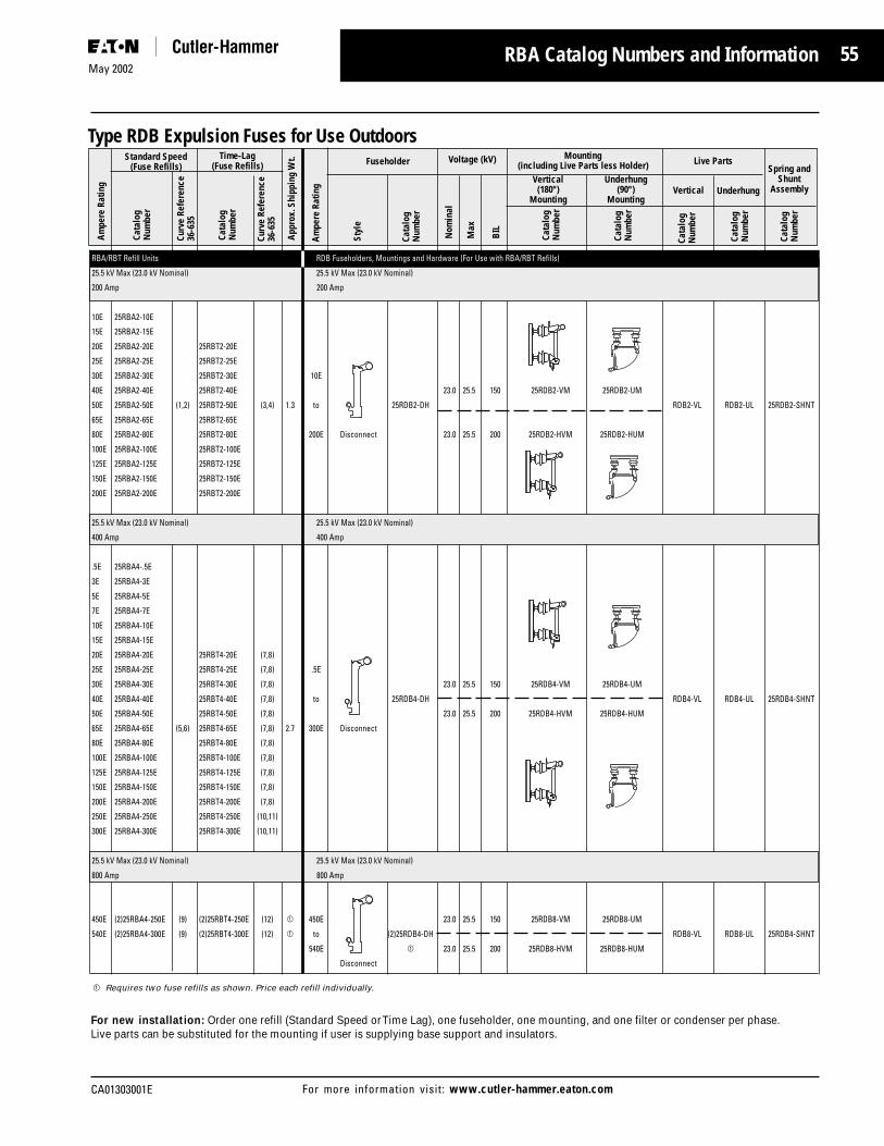
55
CA01303001E
May 2002
For more information visit: www.cutler-hammer.eaton.com
Am
pere
Rat
ing
Curv
e Re
fere
nce
36-6
35
Curv
e Re
fere
nce
36-6
35
Cata
log
Num
ber
Cata
log
Num
ber
Standard Speed(Fuse Refills)
Time-Lag(Fuse Refills)
Cata
log
Num
ber
Fuseholder
Cata
log
Num
ber
Cata
log
Num
ber
Cata
log
Num
ber
Spring andShunt
Assembly
Am
pere
Rat
ing
App
rox.
Shi
ppin
g W
t.
RBA Catalog Numbers and Information
Type RDB Expulsion Fuses for Use Outdoors
RBA/RBT Refill Units RDB Fuseholders, Mountings and Hardware (For Use with RBA/RBT Refills)Ho
25.5 kV Max (23.0 kV Nominal) 25.5 kV Max (23.0 kV Nominal)
200 Amp 200 Amp
10E 25RBA2-10E
15E 25RBA2-15E
20E 25RBA2-20E 25RBT2-20E
25E 25RBA2-25E 25RBT2-25E
30E 25RBA2-30E 25RBT2-30E 10E
40E 25RBA2-40E 25RBT2-40E 23.0 25.5 150 25RDB2-VM 25RDB2-UM
50E 25RBA2-50E (1,2) 25RBT2-50E (3,4) 1.3 to 25RDB2-DH RDB2-VL RDB2-UL 25RDB2-SHNT
65E 25RBA2-65E 25RBT2-65E
80E 25RBA2-80E 25RBT2-80E 200E Disconnect 23.0 25.5 200 25RDB2-HVM 25RDB2-HUM
100E 25RBA2-100E 25RBT2-100E
125E 25RBA2-125E 25RBT2-125E
150E 25RBA2-150E 25RBT2-150E
200E 25RBA2-200E 25RBT2-200E
25.5 kV Max (23.0 kV Nominal) 25.5 kV Max (23.0 kV Nominal)
400 Amp 400 Amp
.5E 25RBA4-.5E
3E 25RBA4-3E
5E 25RBA4-5E
7E 25RBA4-7E
10E 25RBA4-10E
15E 25RBA4-15E
20E 25RBA4-20E 25RBT4-20E (7,8)
25E 25RBA4-25E 25RBT4-25E (7,8) .5E
30E 25RBA4-30E 25RBT4-30E (7,8) 23.0 25.5 150 25RDB4-VM 25RDB4-UM
40E 25RBA4-40E 25RBT4-40E (7,8) to 25RDB4-DH RDB4-VL RDB4-UL 25RDB4-SHNT
50E 25RBA4-50E 25RBT4-50E (7,8) 23.0 25.5 200 25RDB4-HVM 25RDB4-HUM
65E 25RBA4-65E (5,6) 25RBT4-65E (7,8) 2.7 300E Disconnect
80E 25RBA4-80E 25RBT4-80E (7,8)
100E 25RBA4-100E 25RBT4-100E (7,8)
125E 25RBA4-125E 25RBT4-125E (7,8)
150E 25RBA4-150E 25RBT4-150E (7,8)
200E 25RBA4-200E 25RBT4-200E (7,8)
250E 25RBA4-250E 25RBT4-250E (10,11)
300E 25RBA4-300E 25RBT4-300E (10,11)
25.5 kV Max (23.0 kV Nominal) 25.5 kV Max (23.0 kV Nominal)
800 Amp 800 Amp
450E (2)25RBA4-250E (9) (2)25RBT4-250E (12) 1 450E 23.0 25.5 150 25RDB8-VM 25RDB8-UM
540E (2)25RBA4-300E (9) (2)25RBT4-300E (12) 1 to (2)25RDB4-DH RDB8-VL RDB8-UL 25RDB4-SHNT
540E 1 23.0 25.5 200 25RDB8-HVM 25RDB8-HUM
Disconnect
1 Requires two fuse refills as shown. Price each refill individually.
For new installation: Order one refill (Standard Speed or Time Lag), one fuseholder, one mounting, and one filter or condenser per phase.Live parts can be substituted for the mounting if user is supplying base support and insulators.
Styl
e
Live Parts
UnderhungVertical
Voltage (kV)
Cata
log
Num
ber
Mounting(including Live Parts less Holder)
Nom
inal
Max
BIL
Cata
log
Num
ber
Vertical(180°)
Mounting
Underhung(90°)
Mounting
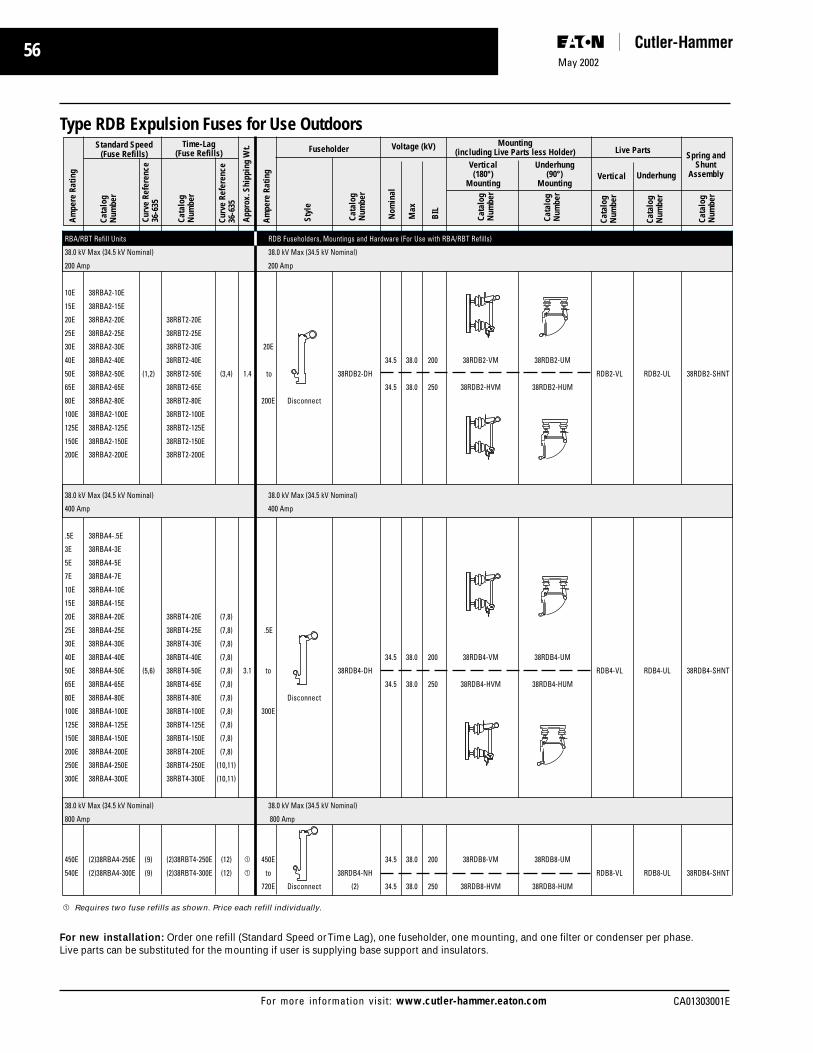
56May 2002
CA01303001EFor more information visit: www.cutler-hammer.eaton.com
1 Requires two fuse refills as shown. Price each refill individually.
For new installation: Order one refill (Standard Speed or Time Lag), one fuseholder, one mounting, and one filter or condenser per phase.Live parts can be substituted for the mounting if user is supplying base support and insulators.
Am
pere
Rat
ing
Curv
e Re
fere
nce
36-6
35
Curv
e Re
fere
nce
36-6
35
Cata
log
Num
ber
Cata
log
Num
ber
Standard Speed(Fuse Refills)
Time-Lag(Fuse Refills)
Cata
log
Num
ber
Fuseholder
Cata
log
Num
ber
Cata
log
Num
ber
Cata
log
Num
ber
Live Parts
Vertical
Spring andShunt
Assembly
App
rox.
Shi
ppin
g W
t.
Type RDB Expulsion Fuses for Use Outdoors
RBA/RBT Refill Units RDB Fuseholders, Mountings and Hardware (For Use with RBA/RBT Refills)
38.0 kV Max (34.5 kV Nominal) 38.0 kV Max (34.5 kV Nominal)
200 Amp 200 Amp
10E 38RBA2-10E
15E 38RBA2-15E
20E 38RBA2-20E 38RBT2-20E
25E 38RBA2-25E 38RBT2-25E
30E 38RBA2-30E 38RBT2-30E 20E
40E 38RBA2-40E 38RBT2-40E 34.5 38.0 200 38RDB2-VM 38RDB2-UM
50E 38RBA2-50E (1,2) 38RBT2-50E (3,4) 1.4 to 38RDB2-DH RDB2-VL RDB2-UL 38RDB2-SHNT
65E 38RBA2-65E 38RBT2-65E 34.5 38.0 250 38RDB2-HVM 38RDB2-HUM
80E 38RBA2-80E 38RBT2-80E 200E Disconnect
100E 38RBA2-100E 38RBT2-100E
125E 38RBA2-125E 38RBT2-125E
150E 38RBA2-150E 38RBT2-150E
200E 38RBA2-200E 38RBT2-200E
38.0 kV Max (34.5 kV Nominal) 38.0 kV Max (34.5 kV Nominal)
400 Amp 400 Amp
.5E 38RBA4-.5E
3E 38RBA4-3E
5E 38RBA4-5E
7E 38RBA4-7E
10E 38RBA4-10E
15E 38RBA4-15E
20E 38RBA4-20E 38RBT4-20E (7,8)
25E 38RBA4-25E 38RBT4-25E (7,8) .5E
30E 38RBA4-30E 38RBT4-30E (7,8)
40E 38RBA4-40E 38RBT4-40E (7,8) 34.5 38.0 200 38RDB4-VM 38RDB4-UM
50E 38RBA4-50E (5,6) 38RBT4-50E (7,8) 3.1 to 38RDB4-DH RDB4-VL RDB4-UL 38RDB4-SHNT
65E 38RBA4-65E 38RBT4-65E (7,8) 34.5 38.0 250 38RDB4-HVM 38RDB4-HUM
80E 38RBA4-80E 38RBT4-80E (7,8) Disconnect
100E 38RBA4-100E 38RBT4-100E (7,8) 300E
125E 38RBA4-125E 38RBT4-125E (7,8)
150E 38RBA4-150E 38RBT4-150E (7,8)
200E 38RBA4-200E 38RBT4-200E (7,8)
250E 38RBA4-250E 38RBT4-250E (10,11)
300E 38RBA4-300E 38RBT4-300E (10,11)
38.0 kV Max (34.5 kV Nominal) 38.0 kV Max (34.5 kV Nominal)
800 Amp 800 Amp
450E (2)38RBA4-250E (9) (2)38RBT4-250E (12) 1 450E 34.5 38.0 200 38RDB8-VM 38RDB8-UM
540E (2)38RBA4-300E (9) (2)38RBT4-300E (12) 1 to 38RDB4-NH RDB8-VL RDB8-UL 38RDB4-SHNT
720E Disconnect (2) 34.5 38.0 250 38RDB8-HVM 38RDB8-HUM
Underhung
Am
pere
Rat
ing
Styl
e
Voltage (kV)
Cata
log
Num
ber
Mounting(including Live Parts less Holder)
Nom
inal
Max
BIL
Cata
log
Num
ber
Vertical(180°)
Mounting
Underhung(90°)
Mounting

57
CA01303001E
May 2002
For more information visit: www.cutler-hammer.eaton.com
DBU Medium Voltage Fuses
DBU Fuses

58May 2002
CA01303001EFor more information visit: www.cutler-hammer.eaton.com

59
CA01303001E
May 2002
For more information visit: www.cutler-hammer.eaton.com
Introduction
The Cutler-Hammer DBU P owerFuse is a Boric Acid, expulsion-stylefuse unit. Suitable for both indoorand outdoor applications, the DBUprovides a low initial costalternative to refillable fuses.
New DBU with End Fittings
In comparison to the conventionaldistribution cutout that utilizes thefiber tube and fuse link design forfault interruption, the DBU farexceeds the cutout in interruptingrating, and considerably reducesthe hazards and noise of the violentexhaust common to cutouts underfault interrupting conditions. TheDBU fuse employing the use ofcalibrated silver elements, boricacid for its interrupting media, andthe mechanical utilization of thespring and rod mechanism, createsa technique which gives a low arcand mild exhaust fault interruption.
DBU Expulsion Fuses are availablein 3 maximum voltage classes:17kV, 27kV, and 38kV. Thereplaceable fuse unit comes in 3speed variations: Standard “E”,Slow “E”, and “K”. Amperagesizes range from 3 Amps through200 Amps.
Construction
In terms of application, thecomplete fuse consists of the fuseunit, end fittings, and a mounting.
Principle parts of the replaceableDBU fuse unit are shown in thecross section view of Fig. 9. Mainoperating parts are the silverelement, arcing rod, boric acidcylinder, and spring. To preventwarping under outdoor conditionsand assure adequate strength tocontain the force of the arcinterruption, a glass epoxy tubeencloses the assembly.
The use of a pure silver elementand Nichrome wire strain elementmakes the DBU less susceptible tooutages caused by vibration,corona corrosion, and aging of thefuse elements. It is not damagedby transient faults or overloadswhich approach the minimum meltpoint.
Figure 9: DBU Fuse Construction
The components are housed in afiberglass reinforced resin tubewith plated copper contacts.Positive connection is maintainedbetween the arcing rod and contact
with a sliding tulip contact. Adurable weatherproof label islocated on each fuse whichprovides ratings and manufacturerinformation.
Operation
DBU Expulsion Fuses utilize theproven performance of boric acid tocreate the de-ionizing actionneeded to interrupt the current.Fault interruption is achieved by theaction of an arcing rod and acharged spring, elongating the arcthrough a boric acid chamber uponrelease by the fuse element.
At high temperatures, boric aciddecomposes producing a blast ofwater vapor and inert boricanhydride. Electrical interruption iscaused by the steam extinguishingthe arc, as the arc is beingelongated through the cylinder.
Higher particle turbulence of theboric acid causes the rate of de-ionization in the cylinder to exceedthe ionization of the electrical arc.Both high and low current faults areinterrupted in the same mannerwith no foreign material other thanthe boric acid required. Thisenables the fuse to interrupt shortcircuits within one-half cycle and
DBU Introduction
Element Rod withdraws, VaporMelts elongating arc quenches
and vaporizing arc at firstBoric Acid current zero

60May 2002
CA01303001EFor more information visit: www.cutler-hammer.eaton.com
DBU Features
prevents the arc from restrikingafter a current zero.
After interruption, the gases areexpelled from the bottom of thefuse. The arcing rod is preventedfrom falling back into its originalposition by a friction stop at the topof the fuse unit.
When the fuse operates, theupward motion of the spring forcesthe top of the arcing rod topenetrate the upper seal, strikingthe latch mechanism. On indoorapplications, this action caused theblown fuse indicator to actuate.
On outdoor installations, the latchreleases the fuse unit allowing theejector spring to move theassembly outward and swingthrough a 180 degree arc into adropout position. This dropoutaction provides immediate visualindication that the fuse hasoperated. When the fuse is blownand the dropout action completed,the entire unit is removed with ahookstick.
Outdoor dropout action.
When replacing the blown fuse, theend fittings should be removedfrom the operated fuse unit, and ifundamaged, clamped onto the newfuse unit.
Application
The DBU Power Fuse provideseffective protection for circuits andequipment which operate onvoltage systems up to 34,500V.They can be used on both electricutility and industrial distributionsystems and all fuses are designedfor use on the following:
■ Power Transformers
■ Feeder Circuits
■ Distribution Transformers
■ Potential Transformers
■ Station Service Transformers
■ Metal-enclosed Switchgear
■ Pad Mount Switches
DBU Fuse units can be used inoutdoor or indoor applications, andcan be used to directly replacecompetitive equivalent units.
WLI gear w/ Fuses
Since the DBU Fuse Unit hassuperb, reliable performancecharacteristics, it can be used onupstream as well as downstreamapplications.
Regarding upstream systemprotection, the DBU operatespromptly to limit the stress onelectrical systems due to shortcircuits. It provides isolation for thefaulted circuit, limiting the amountof interruption to the service.Downstream equipment is equallyprotected. The DBU acts rapidly totake transformer and feeder circuitsoff-line before damage can becomewidespread. It provides excellentisolation for capacitors as well inthe event of a fault condition.
When installed on the primary sideof substation power transformers,DBU fuses provide protectionagainst small, medium or largefaults. Regardless of the nature ofthe fault, full protection is providedeven down to minimum meltcurrent.
DBU Details
The Cutler-Hammer DBU pro videssuperior performance especiallyintended for distribution systemprotection up to an operationalvoltage of 34.5KV. Because theDBU is available in various currentratings and time-currentcharacteristics, close fusing can beachieved to maximize protectionand overall coordination. Thequality of the DBU design andmanufacturing process ensuresrepeatable accuracy and ongoingtime-current protection.
DBU Fuse Unit
A DBU fuse unit is comprised of anarcing rod, an auxiliary arcing wire,a strain element, and a solid boricacid liner which assists with theinterruption. All of thesecomponents are contained within aseparate fiberglass tube. Thefiberglass tube has an end cap onone end with a blowout disk whichpermits exhaust to exit duringinterruption. The fuse elementdetermines the operational time-current characteristics of the DBUfuse unit. How the fuse reacts fordifferent magnitudes of current andamounts of time is indicated on thespecific time-current characteristiccurve. The DBU is available in

61
CA01303001E
May 2002
For more information visit: www.cutler-hammer.eaton.com
Standard “E”, “K”, and Slow “E”configurations.
The heavy copper cylindrical arcingrod is contained within the main boreof the boric acid liner and performstwo functions. Under normalconditions, it conducts thecontinuous rated current of the fuse.
A nichrome wire, called the strainelement, parallels the fuse elementand relieves the fuse element ofany strain put on it by the springloaded arcing rod. The highresistance wire shunts the fuseelement and vaporizes immediatelyafter the fuse element melts.
When the fuse element meltsduring a fault condition, the arcingrod draws and lengthens the arc asit moves up through the boric acidliner. This movement is caused byspring tension placed on the arcingrod by the attached charged spring.
Intense heat from the arcdecomposes the dry boric acid. Ondecomposition, the boric acid formswater vapor and inert boric
anhydride which by blastingthrough it, extinguishes and de-ionizes the arc.
The exhaust caused by theinterruption exits from the bottomof the fuse through the blowoutdisk. This prevents the arc fromrestriking after a current zero.
The replaceable DBU fuse unit isdiscarded after it interrupts a fault.
DBU End Fittings
End Fittings are required tocomplete the electrical connectionbetween the fuse unit and the liveparts and mounting.
End fittings are positioned on thetop and bottom of the fuse unit.They can be used over again if theyremain undamaged.
End Fittings are available in 2versions: indoor and outdoor.
The indoor fittings accept a Mufflerattachment to limit noise andcontamination to indoorequipment. The blown fuse
indicator located on the top endfitting, provides visual indication ofa faulted fuse unit.
Outdoor Fittings
Outdoor end fittings are made of acast-copper plated alloy. A largehookeye on the upper fitting allowsfor easy installation into pole-topmountings with a hookstick. Thepivotal design of this hookeyeprovides for proper engagement ofthe upper live part. The positivelocking action of the latchmechanism prevents detachmentfrom the mounting due to shock orvibration. In the event of a fault,the arcing rod will penetratethrough the upper end of the fuseunit, and cause the latch to release.Once released, the fuse will rotatedown into the drop-out position toindicate a blown-fuse condition.
The lower end fitting has twocylindrical posts that insert into thelower live part of the mounting.These posts allow the fuse to rotateinto the proper engaged position,and suspend the fuse during ablown, drop-out condition.
Indoor DBU Fuse Fittings Outdoor DBU Fuse Fittings
DBU Features

62May 2002
CA01303001EFor more information visit: www.cutler-hammer.eaton.com
DBU Features
Indoor Fittings
The indoor end fittings are composedof high-impact plastic and high-conducting copper alloy. The blownfuse indicator located on the top endfitting, provides visual indication of afaulted fuse unit. The silver-platedcontact rod insures positiveconductivity between the fuse unitand the live parts of the mounting.
The spring-loaded plastic mountinghandle actuates the latch mechanismwhen engaged into the mounting. Itreadily accepts a hookstick to installor remove the assembled fuse unit.
A locating pin in the upper fittingassures proper alignment andengagement with the fuse unit.
The cast bottom indoor fitting has alocating slot on the inside bore. Thisslot aligns with a locating pin on thelower section of the fuse unit toprovide proper alignment with thefuse unit and the mounting. Twopivotal slots are formed into thefitting for mechanical insertion intothe mounting.
The bottom indoor fitting is threadedto accept a Muffler attachment forlimiting noise and contamination toindoor equipment. The Muffler isconstructed of a plated steel housing,containing copper mesh screening.This copper mesh acts to absorb andcontain the noise and exhaustmaterials of the fuse during a faultcondition. The Muffler preventscontamination of indoor componentsand mechanisms located within theswitchgear. This containment actionalso prevents accidental flash-overfrom phase-to-phase or phase-to-ground by limiting foreign airborneparticles and gases.
All end fittings are re-usable ifundamaged. They are completelyinterchangeable with othermanufacturers’ equivalent fuse unitsand mountings.
Mountings & Live Parts
Cutler-Hammer of fers a full line ofloadbreak and non-loadbreakmountings and live parts for theDBU fuse family . Mountings are
available in 17KV, 27KV, and 38KVclass designs.
These mountings will readilyaccommodate all DBU class fusesas well as other equivalentmanufacturers.
All mountings are applicable forindoor applications of pad-mountand switchgear designs.
Units have a maximum currentrating up to 200A, with a maximuminterrupt rating of 14kA. Thefollowing lists the BIL rating of eachvoltage class:
■ 17KV - 95 BIL
■ 27KV - 125 BIL
■ 38KV - 150 BIL
Loadbreak units have a maximum3-time fault close ASYM of 22,400ARMS. Refer to the catalog numbersection for exact ratings per unit.
Non-Loadbreak Mounting
Loadbreak Mounting
Mountings are constructed of rigidsteel bases. Non-load break units aregalvanized while loadbreak styles areepoxy coated. Bases are suppliedwith preformed mounting holes foreasy installation.
Isolators are molded of cycloaliphaticmaterial for superior insulatingcharacteristics. Live parts are rigidlysecured to the isolators withstandard mounting hardware.
Bus for cable terminations for non-loadbreak units are located on the
right side of the mountings.Loadbreak units have both left andright side mountings available forproper installation spacing. All busconnections are plated copper forimproved conductivity andendurance.
All loadbreak units have a 3 timefault close rating. These fusemountings can withstand a fuseassembly being closed into a fault ofthe magnitude specified three timeswhen closed briskly withouthesitation, and remain operable andable to carry and interrupt thecontinuous current.
All live parts are constructed of silver-plated copper to ensure maximumand sustained conductivity.
Live parts can be purchased asseparate kits without mountings.
DBU Interruption andProtection
Discussions have concentrated onthe individual components that makeup a DBU Power Fuse. This sectionwill center around the operation ofthe complete fuse assembly.
When completely assembled, theDBU Power Fuse will provideeffective protection for circuits andequipment which operates onvoltages from 2400 Volts through34,500 Volts. At this point, it would bebeneficial to briefly review the overalloperation of the entire DBU PowerFuse.
The DBU assembly, whetherdisconnect or non-disconnect, ispositioned to perform its protectivefunction as current flows through themounting’s line and load connectors.The DBU fuse unit makes theelectrical connection with themounting through its end fittingswhen properly engaged. A spring-loaded arcing rod carries the normalcontinuous current through the unitwhen the circuit is operational.Under normal conditions, the fusibleelement’s temperature is below itsmelting temperature and does notmelt. When a fault occurs that is

63
CA01303001E
May 2002
For more information visit: www.cutler-hammer.eaton.com
large enough to melt the fuseelement, an arc is initiated andelongated by the units spring, pullingthe arcing rod up into the boric acidinterrupting media. The heatproduced decomposes the boric acidliner inside producing water vaporand boric anhydride which helps tode-ionize the arc. The by-productsextinguish the arc at a natural currentzero by blasting through it andexiting out the bottom of the fuse.When installed indoors, the exhaustand noise produced during theinterruption process are limited bythe muffler attached to the lower endfitting. The DBU fuse unit is thendiscarded, and replaced with a newunit, re-using the end fittings ifundamaged.
This assembly is then re-engagedinto the live parts and mounting.Although the process is moreinvolved than just described, thisshould provide a generalunderstanding of how the DBUPower Fuse works to provideoutstanding and economicalprotection with limited down time.
During the interrupting process,current continues to flow in thecircuit and in the fuse until a currentzero is reached. When the arc isstopped at current zero, the voltagewill attempt to re-ignite the arc. Thevoltage across the fuse terminalsbuilds dramatically and is referred toas the Transient Recovery Voltage(TRV). The TRV is the most severewaveform the fuse will have towithstand. This voltage build-upputs a great deal of potentiallydestructive force on the fuse unitsand the system in total. Whether ornot extinguishing of the arc issuccessful depends, in general, onthe dielectric strength between thefuse terminals. In short, the dielectricstrength between the fuse terminalsmust be greater than the voltagetrying to re-ignite the arc for asuccessful interruption to occur.When properly applied, the DBUPower Fuse has a dielectric recoverythat is greater than the TRV,regardless of the fault current.(Refer to Table 1)
The maximum voltage rating of theDBU fuse is the highest rms voltageat which the fuse is designed tooperate. Its dielectric withstand levelcorresponds to insulation levels ofpower class equipment, thus thename “power fuse”. Maximumvoltage ratings for DBU Power Fusesare: 17KV, 27KV, and 38KV.
No fuse should ever be appliedwhere the available fault currentexceeds the interrupting rating ofthe fuse. The rated interruptingcapacity of the DBU is the rms
value of the symmetricalcomponent (AC component) of thehighest current which the DBU isable to successfully interrupt underany conditions of asymmetry. Inshort, the interrupting rating mustbe equal to or greater than themaximum symmetrical fault currentat the point where the fuse isapplied. The DBU has interruptingcapabilities from 10,000 to 14,000amperes symmetrical.
The continuous current rating of aDBU Power Fuse should equal or
Primary Faults Secondary Faults
Test Circuit - Test Circuit -Fuse Rating Normal TRV TRV Normal TRV TRVkV Normal Frequency Natural Amplitude Frequency Natural Amplitude
Recovery Frequency, Factor Recovery Frequency, FactorVoltage, Kc Voltage, KckV rms kV rms
14.4 17.1 5.5 1.6 14.4 17 1.725 27 5.5 1.6 27 13 1.734.5 38 3.9 1.6 38 6.5 1.7
Table 1: TRV Characteristics
Table 2: DBU Power Fuse Short-Circuit Interrupting Ratings
kV, Nominal Amperes, Interrupting MVA, Interrupting(Three-PhaseSymmetrical)
Symmetrical WhereDBU System based on Asymmetrical X/R = 15
X/R = 15
7.2 1754.8 / 8.32Y 2007.2 / 12.47Y 300
17 7.62 / 13.2Y 14000 22400 32013.8 33514.4 35016.5 400
7.2 / 12.47Y 2707.62 / 13.2Y 28513.8 30014.4 310
27 16.5 12500 20000 36523.0 50014.4 / 24.9Y 54020 / 34.5Y 1 ...
23.0 ...14.4 / 24.9Y ...
38 27.6 10000 16000 47520 / 34.5Y 60034.5 600
1 Applies to 23kV Single-Insulator Style only, for Protection of single-phase-to-neutral circuits (line ortransformers) and three-phase transformers or banks with solidly grounded neutral connections.
DBU Features

64May 2002
CA01303001EFor more information visit: www.cutler-hammer.eaton.com
exceed the maximum load cur rentwhere the fuse is applied. They aredesigned to carry their ratedcontinuous current withoutexceeding the temperature riseoutlined in NEMA and ANSIstandards.
The DBU is available withcontinuous current ratings up to200 amperes. The current ratingscarry an “E” designation as definedby ANSI and NEMA. For example,the current responsive elementrated 100E amperes or below shallmelt in 300 seconds at an rmscurrent within the range of 200 to240 percent of the continuouscurrent ratings. Above 100Eamperes, melting takes place in 600seconds at an rms current withinthe range of 220 to 264 percent ofthe continuous current rating. Slow“E”and “K” speeds are alsoavailable.
Coordination Consideration
Coordination considerations mustbe made to help determine whattype of fuse is applied. The DBUPower Fuse interrupts at a naturalcurrent zero in the current waveand allows a minimum of a halfcycle of fault current to flow beforethe fault is cleared. The time-current characteristics associatedwith a DBU has a rather gradualslope making it easier to coordinatewith downstream equipment. Inaddition, the DBU is ideal for highervoltage (up to 38 kV) and highcurrent applications (thru 200Amps). It is important to examinethe minimum melting and totalclearing time-current characteristicsof this particular fuse.
The melting time is the time inseconds required to melt the fuseelement. This curve indicates whenor even if the element of the fusewill melt for different symmetricalcurrent magnitudes.
The total clearing time is thetotal amount of time it takes toclear a fault once the element hasmelted. The total clearing time isreally the sum of the melting time
and the time the fuse arcs duringthe clearing process.
The DBU Power Fuse is offered in 3configurations for use with highcurrents: “E” (Standard), “K” (Fast)and “SE” (Slow). The curves for the“SE” are less inverse and allow formore of a time delay at high currents.
Finally, low currents, usuallyreferred to as overload currents,must also be considered. The DBUand other expulsion fuses have arather low thermal capacity andcannot carry overloads of the samemagnitude and duration as motorsand transformers of equalcontinuous currents. For thisreason, the fuse must be sized withthe full load current in mind. Thisconsideration should be made sothe fuse does not blow onotherwise acceptable overloads andinrush conditions.
The Cutler-Hammer DBU family ofpower fuses is broad andcomprehensive. Refer to the DBURatings Table 2 to review theratings available for mostapplication requirements. The finalselection process for newapplications will include the fuseunit, end fittings, and a mounting.
DBU Features

65
CA01303001E
May 2002
For more information visit: www.cutler-hammer.eaton.com
DBU Dimensional Details
Indoor DBU Fuse Fittings
B
0.50 x 0.75Mtg. Slots
(4)
0.5
2.03
Side View
CD
Mounting Base Detail
1.505.50
Front View(fuse removed)
A B
3.06.50
K
0.75
0.56 DIA.
F
E
2.03
G
H
J
1.88
3.50
L
M
43°
Side View
D1.0
Front View(fuse removed)
B
2.0
K
0.63
0.56 DIA.NEMA (2)
F
E
2.03
0.75
1.0
0.50
0.56 DIA.
0.50
1.69
3.38
0.63
Outdoor DBU Fuse Fittings
Non-Loadbreak Mounting
Fuse Unit FittingskV
Max. A B
17 19.08 19.41
27 22.58 22.91
38 28.76 29.09
Fuse Mounting (Dimensions in Inches)kV Catalog kV
Max. Number BIL A B C D E F G H J K L M
17 DBU17-GDML** 95 22.50 18.44 30.50 19.25 14.25 9.25 18.44 9.44 11.50 3.0 9.50 3.75
17 DBU17-GDMR* 95 22.50 18.44 30.50 19.25 14.25 9.25 18.44 9.44 11.50 3.0 9.50 3.75
27 DBU17-GDML** 125 26.75 22.69 34.63 21.38 16.75 11.56 22.69 11.75 13.50 3.0 9.50 3.75
27 DBU17-GDMR* 125 26.75 22.69 34.63 21.38 16.75 11.56 22.69 11.75 13.50 3.0 9.50 3.75
38 … … … … … … … … … … … … … …
* Bus for cable termination on right side of mounting.* Bus for cable termination on left side of mounting.
kV Fuse Unit FittingsMax.
A B C
17 19.08 27.19 28.82
27 22.58 30.69 32.32
38 28.76 36.87 38.50
Loadbreak Mounting
kV Fuse Mounting (Dimensions in Inches)Max. Catalog kV
Number* BIL B D E F K
17 DBU17-GNM 95 17.75 17.63 12.63 9.50 3.0
27 DBU27-GNM 95 22.25 19.19 14.44 11.06 3.0
38 DBU38-GNM 150 28.25 22.0 17.25 13.63 3.0
* Bus for cable termination on right side of mounting.

66May 2002
CA01303001EFor more information visit: www.cutler-hammer.eaton.com
Testing and Performance
■ Standards
■ Testing
■ Quality Standards
Cutler-Hammer does notcompromise when performance,quality and safety are involved.Exacting standards have beenestablished relative to the design,testing and application ofexpulsion type power fuses.Compliance with these standardsensures the best selection andperformance.
Type DBU P ower Fuses aredesigned and tested to applicableportions of ANSI standards as wellas other industry standards. TheANSI standards are ConsensusStandards jointly formulated byIEEE and NEMA.
IEEE (Institute of Electrical andElectronic Engineers) is anobjective technical organizationmade up of manufacturers, usersand other general interest parties.NEMA (National ElectricalManufacturers Association) is anelectrical equipment manufactureronly organization with memberslike Cutler-Hammer. ANSI(American National StandardsInstitute) is a nonprofit, privatelyfunded membership organizationthat coordinates the developmentof U.S. voluntary nationalstandards. It is also the U.S.member body to the non-treatyinternational standards bodies,such as International Organizationfor Standardization (ISO) and theInternational ElectrotechnicalCommission (IEC).
The specific standards associatedwith DBU Power Fuses are:
■ ANSI C37.40 - Service Conditionsand Definitions
■ ANSI C37.41 - Power FuseDesign and Testing
■ ANSI C37.42 - Distribution FuseRatings and Specification
■ ANSI C37.46 - Power FuseRatings and Specifications
■ ANSI C37.48 - Power FuseApplication, Operation andMaintenance
Testing
DBU Power Fuse unit design testingwas performed on standardproduction fuses, holders,mountings and accessories.Demanding tests were performed atthe Cutler-Hammer TechnicalCenter and also at recognizedindependent power testinglaboratories. Thermal andinterrupting testing was conductedat 17, 27, and 38kV levels. Theentire series of tests was conductedin a specific sequence as stipulatedby governing standards withoutany maintenance being performed.All test results are verified bylaboratory tabulations andoscillogram plots.
Quality
Every effort is made to ensure thedelivery of quality fuse units andcustomer satisfaction. All Cutler-Hammer fuses are completelyinspected at each manufacturingstage.
In addition to ongoing qualitycontrol inspections, testing isperformed prior to shipment. AMicro-Ohm R esistance Test isperformed on each fuse to assureproper element construction,alignment and tightness ofelectrical connections. Constructionintegrity testing is also performedon every unit.
Each DBU fuse unit is checked toensure that all items are supplied inkeeping with manufacturingdrawings. Individual fuses arepacked in a plastic bag and then putinto individual cartons. In addition,fuses are overpacked in a shippingcarton to prevent shipping damage.Finally, mountings are packaged inheavy cardboard containers withreinforced wooden bases.
DBU Testing and Performance

67
CA01303001E
May 2002
For more information visit: www.cutler-hammer.eaton.com
DBU Installation
1. Installation for New DBUApplications
1.1 Installation (Fusing) in Pad-
Mount/Indoor Applications with
Exhaust Control Device
Attach fuse-unit end fittings (Fig.10) as follows:
A. The lower end fitting must beattached first. Remove anddiscard the blue cap located onthe lower end of the fuse unit.Next, slip the lower end fittingover the upper end of the fuseunit and slide it down until thelocating slot is seated on thelocating pin of the lower ferrule.Then thread the Exhaust ControlDevice onto the lower end fittingand screw it on firmly. The finalfractional turn should be madewith a bar or wrench handle.
B. Slip the upper end fitting overthe fuse unit. Align the locatingpin (inside the upper end fitting)with the locating slot in the FuseUnit and seat the upper endfirmly against the upper end ofthe Fuse Unit. Tighten theclamp screw firmly.
CAUTION
ANY AND ALL APPLICABLE SAFETYREGULATIONS MUST BE STRICTLY
ADHERED TO CONCERNING THECLOSURE OR POSSIBLE CLOSURE OF
DBU FUSE UNITS ONTO “LIVE”CIRCUITS.
1.1.1 Unused Fuse-Unit End
Fittings
A coating of oxidation-inhibitinggrease was applied to the contactrod at the factory. Verify thepresence of the oxidation-inhibiting grease, and that it is stillfree of (from) contaminants. Ifnecessary, clean the contact rodwith a nontoxic, nonflammablesolvent and apply a coating ofoxidation-inhibiting grease. EndFittings should be stored in theoriginal shipping package (ifpossible) in an area free fromexcessive moisture. End Fittingsshould only be attachedimmediately prior to installation.
1.1.2 Re-used Fuse-Unit End
Fittings
Remove the existing coating ofoxidation-inhibiting grease, and dirtfrom the contact rod using anontoxic, nonflammable solvent.Inspect the contact rod for evidenceof pitting. If pitting has occurred,file down any projections, abradethe surface, until smooth with anabrasive cloth or scratch brush, andwipe clean. Apply a new coating ofoxidation-inhibiting grease, to thecontact rod. If the contact has beenburned, the contact and its matingpart should be replaced.
1.2 Installation (Fusing) in Outdoor
Mountings
Attach the fuse-unit end fittings(Fig. 11) as follows:
A. The lower end fitting must beattached first. Slip the lower endfitting over the upper end of thefuse unit and slide it down untilthe locating slot seats on thelocating pin of the lower FuseUnit ferrule. Next, back off thelocknut on the clamp screw andtighten the clamp screw firmly;secure it with the locknut.
B. Slip the upper end fitting overthe fuse unit. Align the locating
pin (inside the upper end fitting)with the locating slot in the FuseUnit and seat the upper endfitting firmly against the upperend of the Fuse Unit. Tighten theclamp screw firmly. Do notremove the blue outer cap fromthe bottom of the Fuse Unit.
1.2.1 Unused Fuse-Unit End Fittings
A coating of oxidation-inhibitinggrease was applied to the contactrod at the factory. Verify thepresence of this oxidation-inhibiting grease, and that it is stillfree of (from) contaminants. Ifnecessary, clean the contact rodwith a nontoxic, nonflammablesolvent and apply a coating ofoxidation-inhibiting grease. EndFittings should be stored in theoriginal shipping package (ifpossible) in an area free fromexcessive moisture. End Fittingsshould only be attachedimmediately prior to installation.
1.2.2 Re-used Fuse-Unit End
Fittings
Remove the existing coating ofoxidation-inhibiting grease, and dirtfrom the contact rod using anontoxic, nonflammable solvent.Inspect the contact rod for evidenceof pitting. If pitting has occurred,file down any projections, abradethe surface, until smooth with anabrasive cloth or scratch brush, andwipe clean. Apply a new coating ofoxidation-inhibiting grease, to thecontact rod. If the contact has beenburned, the contact and its matingpart should be replaced.
2. Replacement of existingApplications
2.1 Replacement (Refusing) in
Pad-Mount/Indoor Applications
with Exhaust Control Device
A. When the fuse operates, the fuseunit does not swing open but theblown-fuse indicator moves tothe extended position, providingvisual evidence that the Fuse Unithas operated. Move the FuseUnit to the open position andthen remove it from the
Figure 10: Indoor DBU Fuse Fittings

68May 2002
CA01303001EFor more information visit: www.cutler-hammer.eaton.com
DBU Installation
mounting. Note: Non-loadbreakmountings do not incorporate alive switching device. Hence, anunblown DBU Fuse Unit in suchmountings must not be moved tothe open position without firstopening an upstream seriesinterrupting and isolating switchor loadbreak elbow.
B. Loosen the upper end fittingclamp screw, and pry the clampapart slightly using a screwdriver.Slide the upper end fitting off theupper end of the Fuse Unit. Thenunscrew and remove the ExhaustControl Device. Slide the lowerend fitting off the upper end ofthe Fuse Unit. (Refer to Figure10.)
C. Attach the end fittings andmuffler to a new Fuse Unit,following the instructions givenabove. A Fuse Unit that hasoperated cannot be salvaged.Discard it.
D. To avoid delay due totransferring of end fittings, sparesets of end fittings and exhaustcontrol devices may be kept onhand for attachment to new FuseUnits immediately before re-fusing is to be performed.
The use of a pure silver elementand Nichrome strain elementmakes the DBU less susceptible tooutages caused by vibration,corona corrosion, and aging of thefuse elements, nor is it damagedby transient faults or overloadswhich approach the minimummelting point.
2.2 Replacement (Refusing) in
Outdoor Mountings
A. When the fuse operates, the FuseUnit swings to the open position.Remove it from the mounting,using a universal pole equippedwith a suitable fuse handlingattachment. Examine the end ofthe fuse unit to determine thatthe actuating pin (see Figure 11)extends through the upper seal,indicating that the fuse unit hasoperated.
B. Loosen the upper and lower endfitting clamp screws (pry theupper end fitting clamp apartslightly with a screwdriver), andslide both end fittings off theupper end of the Fuse Unit.
C. Next, attach the end fittings to anew Fuse Unit, following theinstructions given above. A FuseUnit that has operated cannot besalvaged. Discard it.
D. To avoid delay due totransferring of end fittings, sparesets of end fittings may be kepton hand for attachment to newFuse Units immediately before re-fusing is to be performed.
2.2.1 Unused Fuse-Unit End Fittings
A coating of oxidation-inhibitinggrease was applied to the contactrod at the factory. Verify thepresence of this oxidation-inhibiting grease, and that it is stillfree of (from) contaminants. Ifnecessary, clean the contact rodwith a nontoxic, nonflammablesolvent and apply a coating of
oxidation-inhibiting grease. EndFittings should be stored in theoriginal shipping package (ifpossible) in an area free fromexcessive moisture. End Fittingshould only be attachedimmediately prior to installation.
2.2.2 Re-used Fuse-Unit End
Fittings
Remove the existing coating ofoxidation-inhibiting grease, and anydirt from the contact rod using anontoxic, nonflammable solvent.Inspect the contact rod for evidenceof pitting. If pitting has occurred,file down any projections, abradethe surface, until smooth with anabrasive cloth or scratch brush, andwipe clean. Apply a new coating ofoxidation-inhibiting grease, to thecontact rod. If the contact has beenburned, the contact and its matingpart should be replaced.
Figure 11: Outdoor DBU Fuse Fittings

69
CA01303001E
May 2002
For more information visit: www.cutler-hammer.eaton.com
DBU Fuse Curves
TIM
E IN
SE
CO
ND
S
100009000800070006000
5000
4000
3000
2000
1000900800700600
500
400
300
200
10090807060
50
40
30
20
109876
5
4
3
2
1.9.8.7.6
.5
.4
.3
.2
.1.09.08.07.06
.05
.04
.03
.02
.01
CURRENT IN AMPERES
1000
0090
000
8000
070
000
6000
0
5000
0
4000
0
3000
0
2000
0
1000
090
0080
0070
0060
00
5000
4000
3000
2000
100090
080
070
060
0
500
400
300
200
100
90807060504030201098765
200 SE
175 SE
150 SE
125 SE
100 SE
80 SE
65 SE
50 SE
40 SE
30 SE
25 SE
20 SE
15 SE
Type DBU Slow E Speed Fuses CURVE 36-643 # 10Minimum Melting Time-Current Characteristics - 17.1 - 38 kV July 21, 1999
Reference # 667026Curves are based on tests starting with fuse unit at ambient temperature of 25°C and without initial load.Curves are plotted to minimum test points so all variations should be positive.

70May 2002
CA01303001EFor more information visit: www.cutler-hammer.eaton.com
DBU Fuse Curves
TIM
E IN
SE
CO
ND
S10000
9000800070006000
5000
4000
3000
2000
1000900800700600
500
400
300
200
10090807060
50
40
30
20
109876
5
4
3
2
1.9.8.7.6
.5
.4
.3
.2
.1.09.08.07.06
.05
.04
.03
.02
.01
CURRENT IN AMPERES
1000
0090
000
8000
070
000
6000
0
5000
0
4000
0
3000
0
2000
0
1000
090
0080
0070
0060
00
5000
4000
3000
2000
100090
080
070
060
0
500
400
300
200
10090807060504030201098765
3 E
5 E
7 E
10 E
13 E
200 E
175 E
150 E
125 E
100 E
80 E
65 E
50 E
40 E
30 E
25 E
20 E
15 E
Type DBU Standard E Speed Fuses CURVE 36-643 # 11Minimum Melting Time-Current Characteristics - 17.1 - 38 kV July 21, 1999
Reference # 667027Curves are based on tests starting with fuse unit at ambient temperature of 25°C and without initial load.Curves are plotted to minimum test points so all variations should be positive.

71
CA01303001E
May 2002
For more information visit: www.cutler-hammer.eaton.com
DBU Fuse Curves
TIM
E IN
SE
CO
ND
S
100009000800070006000
5000
4000
3000
2000
1000900800700600
500
400
300
200
10090807060
50
40
30
20
109876
5
4
3
2
1.9.8.7.6
.5
.4
.3
.2
.1.09.08.07.06
.05
.04
.03
.02
.01
CURRENT IN AMPERES
1000
0090
000
8000
070
000
6000
0
5000
0
4000
0
3000
0
2000
0
1000
090
0080
0070
0060
00
5000
4000
3000
2000
100090
080
070
060
0
500
400
300
200
10090807060504030201098765
3 K
6 K
8 K
10 K
12 K
200 K
140 K
100 K
80 K
65 K
50 K
40 K
30 K
25 K
20 K
15 K
Type DBU Standard K Speed Fuses CURVE 36-643 # 12Minimum Melting Time-Current Characteristics - 17.1 - 38 kV July 21, 1999
Reference # 667028Curves are based on tests starting with fuse unit at ambient temperature of 25°C and without initial load.Curves are plotted to minimum test points so all variations should be positive.

72May 2002
CA01303001EFor more information visit: www.cutler-hammer.eaton.com
DBU Fuse Curves
TIM
E IN
SE
CO
ND
S10000
9000800070006000
5000
4000
3000
2000
1000900800700600
500
400
300
200
10090807060
50
40
30
20
109876
5
4
3
2
1.9.8.7.6
.5
.4
.3
.2
.1.09.08.07.06
.05
.04
.03
.02
.01
CURRENT IN AMPERES
1000
0090
000
8000
070
000
6000
0
5000
0
4000
0
3000
0
2000
0
1000
090
0080
0070
0060
00
5000
4000
3000
2000
100090
080
070
060
0
500
400
300
200
10090807060504030201098765
200SE
175SE
150SE
125SE
100SE
80SE
65SE
50SE
40SE
30SE
25SE
20SE
15SE
Type DBU Slow E Speed Fuses CURVE 36-643 # 13Total Clearing Time-Current Characteristics - 17.1 kV July 21, 1999
Reference # 667029Curves are based on tests starting with fuse unit at ambient temperature of 25°C and without initial load.Curves are plotted to maximum test points so all variations should be negative.

73
CA01303001E
May 2002
For more information visit: www.cutler-hammer.eaton.com
DBU Fuse Curves
TIM
E IN
SE
CO
ND
S
100009000800070006000
5000
4000
3000
2000
1000900800700600
500
400
300
200
10090807060
50
40
30
20
109876
5
4
3
2
1.9.8.7.6
.5
.4
.3
.2
.1.09.08.07.06
.05
.04
.03
.02
.01
CURRENT IN AMPERES
1000
0090
000
8000
070
000
6000
0
5000
0
4000
0
3000
0
2000
0
1000
090
0080
0070
0060
00
5000
4000
3000
2000
100090
080
070
060
0
500
400
300
200
10090807060504030201098765
200E
175E
150E
125E
100E
80E
65E
50E
40E
30E
25E
20E
15E
13E
10E
7E
5E
Type DBU Standard E Speed Fuses CURVE 36-643 # 14Total Clearing Time-Current Characteristics - 17.1 kV July 21, 1999
Reference # 667030Curves are based on tests starting with fuse unit at ambient temperature of 25°C and without initial load.Curves are plotted to maximum test points so all variations should be negative.
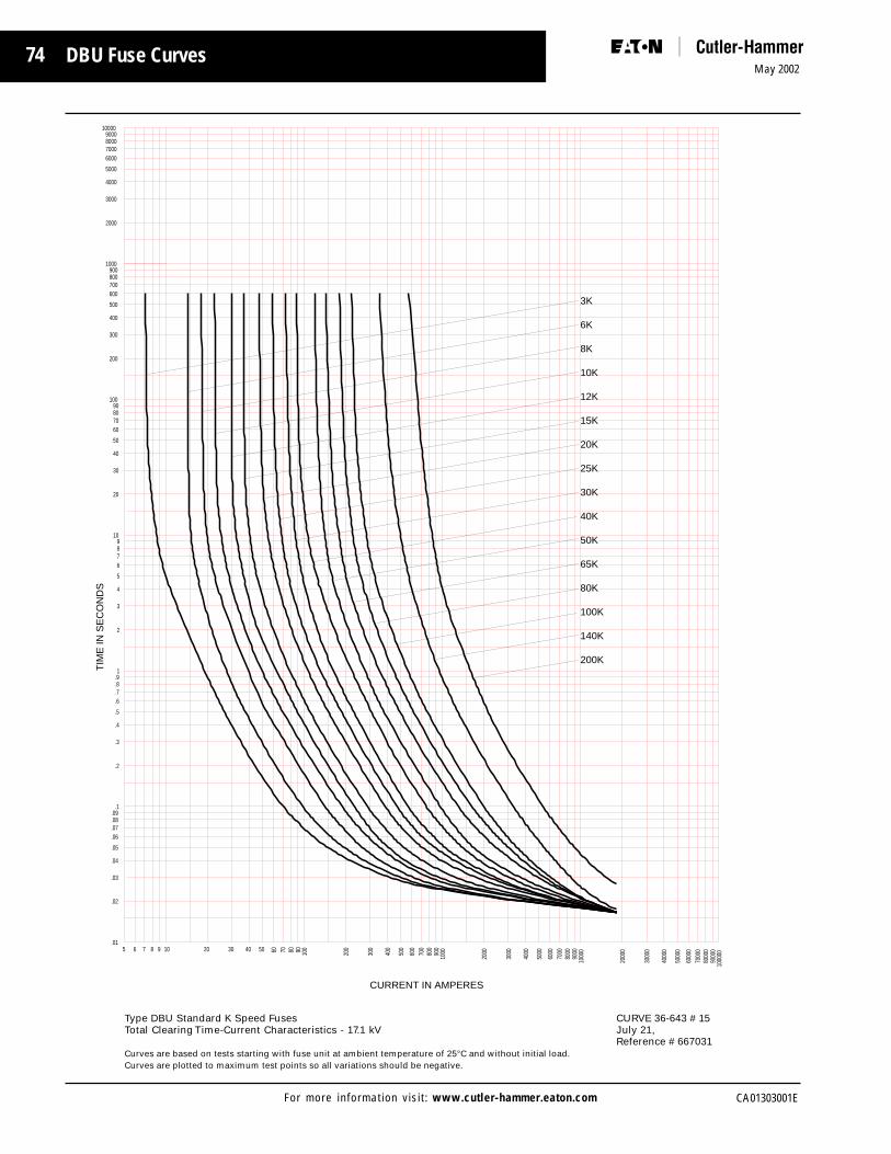
74May 2002
CA01303001EFor more information visit: www.cutler-hammer.eaton.com
DBU Fuse Curves
TIM
E IN
SE
CO
ND
S
100009000800070006000
5000
4000
3000
2000
1000900800700600
500
400
300
200
10090807060
50
40
30
20
109876
5
4
3
2
1.9.8.7.6
.5
.4
.3
.2
.1.09.08.07.06
.05
.04
.03
.02
.01
CURRENT IN AMPERES
1000
0090
000
8000
070
000
6000
0
5000
0
4000
0
3000
0
2000
0
1000
090
0080
0070
0060
00
5000
4000
3000
2000
100090
080
070
060
0
500
400
300
200
10090807060504030201098765
200K
140K
100K
80K
65K
50K
40K
30K
25K
20K
15K
12K
10K
8K
6K
3K
Type DBU Standard K Speed Fuses CURVE 36-643 # 15Total Clearing Time-Current Characteristics - 17.1 kV July 21,
Reference # 667031Curves are based on tests starting with fuse unit at ambient temperature of 25°C and without initial load.Curves are plotted to maximum test points so all variations should be negative.

75
CA01303001E
May 2002
For more information visit: www.cutler-hammer.eaton.com
DBU Fuse Curves
TIM
E IN
SE
CO
ND
S
100009000800070006000
5000
4000
3000
2000
1000900800700600
500
400
300
200
10090807060
50
40
30
20
109876
5
4
3
2
1.9.8.7.6
.5
.4
.3
.2
.1.09.08.07.06
.05
.04
.03
.02
.01
CURRENT IN AMPERES
1000
0090
000
8000
070
000
6000
0
5000
0
4000
0
3000
0
2000
0
1000
090
0080
0070
0060
00
5000
4000
3000
2000
100090
080
070
060
0
500
400
300
200
10090807060504030201098765
200SE
175SE
150SE
125SE
100SE
80SE
65SE
50SE
40SE
30SE
25SE
20SE
15SE
Type DBU Slow E Speed Fuses CURVE 36-643 # 16Total Clearing Time-Current Characteristics - 27 and 38 kV January 5, 2000
Reference # 667038Curves are based on tests starting with fuse unit at ambient temperature of 25°C and without initial load.Curves are plotted to maximum test points so all variations should be negative.
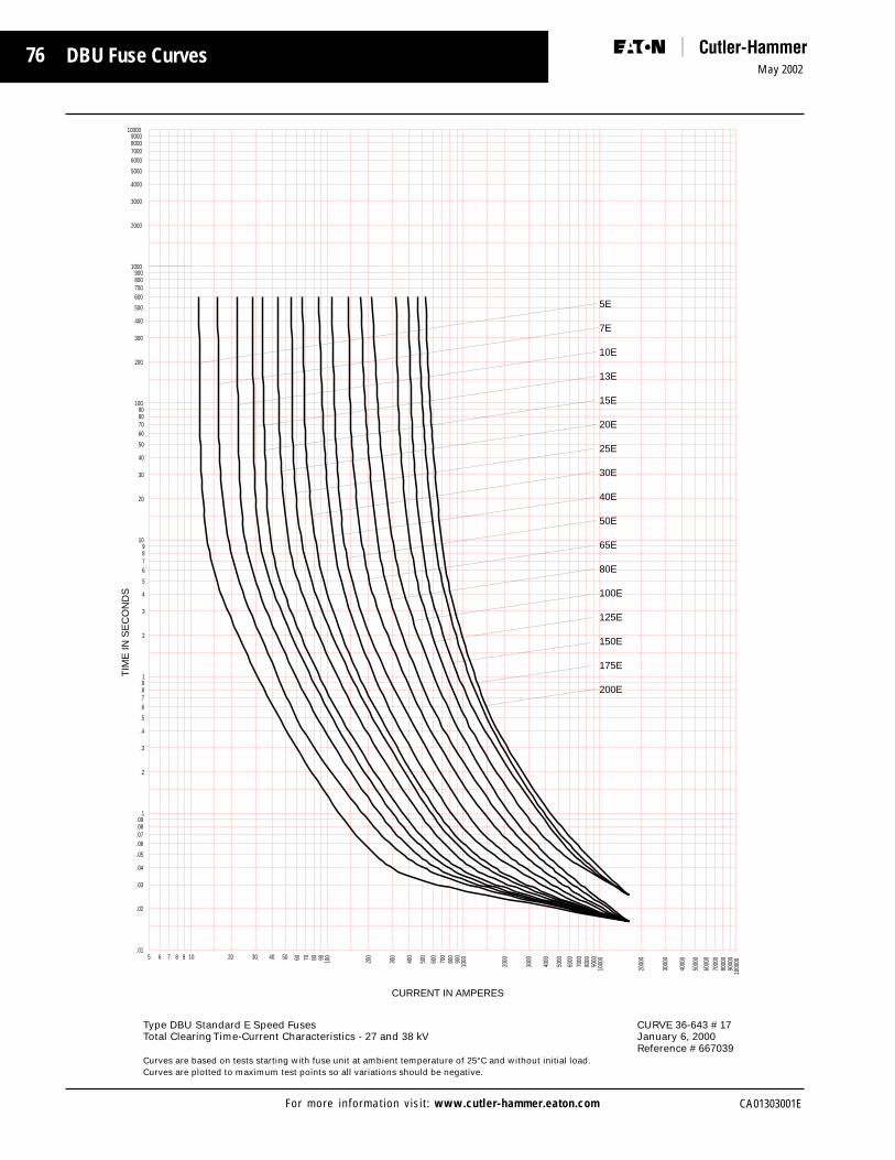
76May 2002
CA01303001EFor more information visit: www.cutler-hammer.eaton.com
DBU Fuse Curves
TIM
E IN
SE
CO
ND
S10000
9000800070006000
5000
4000
3000
2000
1000900800700600
500
400
300
200
10090807060
50
40
30
20
109876
5
4
3
2
1.9.8.7.6
.5
.4
.3
.2
.1.09.08.07.06
.05
.04
.03
.02
.01
CURRENT IN AMPERES
1000
0090
000
8000
070
000
6000
0
5000
0
4000
0
3000
0
2000
0
1000
090
0080
0070
0060
00
5000
4000
3000
2000
100090
080
070
060
0
500
400
300
200
10090807060504030201098765
200E
175E
150E
125E
100E
80E
65E
50E
40E
30E
25E
20E
15E
13E
10E
7E
5E
Type DBU Standard E Speed Fuses CURVE 36-643 # 17Total Clearing Time-Current Characteristics - 27 and 38 kV January 6, 2000
Reference # 667039Curves are based on tests starting with fuse unit at ambient temperature of 25°C and without initial load.Curves are plotted to maximum test points so all variations should be negative.
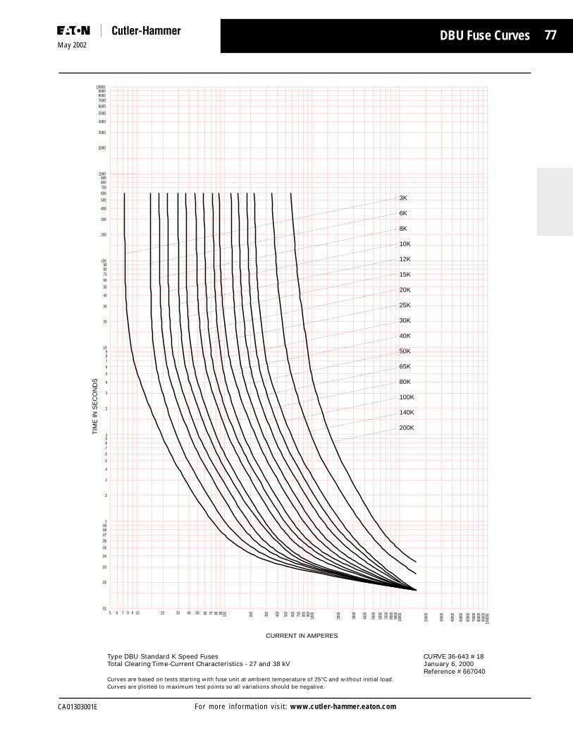
77
CA01303001E
May 2002
For more information visit: www.cutler-hammer.eaton.com
DBU Fuse Curves
TIM
E IN
SE
CO
ND
S10000
9000800070006000
5000
4000
3000
2000
1000900800700600
500
400
300
200
10090807060
50
40
30
20
109876
5
4
3
2
1.9.8.7.6
.5
.4
.3
.2
.1.09.08.07.06
.05
.04
.03
.02
.01
CURRENT IN AMPERES
1000
0090
000
8000
070
000
6000
0
5000
0
4000
0
3000
0
2000
0
1000
090
0080
0070
0060
00
5000
4000
3000
2000
100090
080
070
060
0
500
400
300
200
10090807060504030201098765
200K
140K
100K
80K
65K
50K
40K
30K
25K
20K
15K
12K
10K
8K
6K
3K
Type DBU Standard K Speed Fuses CURVE 36-643 # 18Total Clearing Time-Current Characteristics - 27 and 38 kV January 6, 2000
Reference # 667040Curves are based on tests starting with fuse unit at ambient temperature of 25°C and without initial load.Curves are plotted to maximum test points so all variations should be negative.

78May 2002
CA01303001EFor more information visit: www.cutler-hammer.eaton.com
Type DBU Expulsion Fuses for Use Indoors or Outdoors
DBU Catalog Numbers and InformationRa
ting
Am
pere
s
Curv
e Re
fere
nce
36-6
43
Cata
log
Num
ber
Max
. Int
. kA
Sym
End
Fitti
ngs
Voltage (kV)
Mou
ntin
gs
End
Fitti
ngs
Nom
inal
Max
BIL
Am
pere
Rat
ing
Styl
e
App
rox.
Shi
ppin
g W
t.
(Incl
udes
L iv e
Par
ts)
3K DBU17-3K 14.4 17.0 956K DBU17-6K8K DBU17-8K
10K DBU17-10K12K DBU17-12K15K DBU17-15K20K DBU17-20K 12, 15 14 2.125K DBU17-25K30K DBU17-30K 14.4 17.0 9540K DBU17-40K50K DBU17-50K65K DBU17-65K80K DBU17-80K
100K DBU17-100K140K DBU17-140K200K DBU17-200K
5E DBU17-5E 14.4 17.0 957E DBU17-7E
10E DBU17-10E13E DBU17-13E15E DBU17-15E20E DBU17-20E25E DBU17-25E30E DBU17-30E 11, 14 14 2.140E DBU17-40E50E DBU17-50E 14.4 17.0 9565E DBU17-65E80E DBU17-80E
100E DBU17-100E125E DBU17-125E150E DBU17-150E175E DBU17-175E200E DBU17-200E
15E DBU17-15SE 14.4 17 9520E DBU17-20SE25E DBU17-25SE30E DBU17-30SE40E DBU17-40SE50E DBU17-50SE65E DBU17-65SE 10,13 14 2.180E DBU17-80SE 14.4 17 95
100E DBU17-100SE125E DBU17-125SE150E DBU17-150SE175E DBU17-175SE200E DBU17-200SE
Indoor
Voltage (kV)
Nom
inal
Max
BIL
Fuse
Mou
ntin
g
Outdoor
Am
pere
Rat
ing
Non-
L oad
brea
k
DBU1
7 -GN
M
DBU1
7 -NL
L oad
brea
k
DBU1
7 -GD
M*
DBU1
7 -DL
*
Non-
L oad
brea
k
DBU1
7 -GN
M
DBU1
7 -NL
L oad
brea
k
DBU1
7 -GD
M*
DBU1
7 -DL
*
Non-
L oad
brea
k
DBU1
7 -GN
M
DBU1
7 -NL
L oad
brea
k
DBU1
7 -GD
M*
DBU1
7 -DL
*
DBU-
EFID
3K to
200
K
DBU-
EFOD
3K to
20 0
K
DBU-
EFID
5E to
200
E
DBU-
EFOD
5E to
20 0
E
DBU-
EFID
15SE
to 2
00SE
DBU-
EFOD
1 5SE
to 2
0 0SE
Cata
log
Num
ber
Dis
conn
ect
Fuse
Mou
ntin
g
Cata
log
Num
ber
Catalog Number
Live
Par
ts o
nly
Styl
e
Cata
log
Num
ber
* To complete the Catalog Number, specify “R” for right side cable termination or “L” for left side cable termination.
Note: Muffler can be ordered separately. Order Catalog number DBU-MFLR.

79
CA01303001E
May 2002
For more information visit: www.cutler-hammer.eaton.com
DBU Catalog Numbers and Information
Type DBU Expulsion Fuses for Use Indoors or Outdoors
3K DBU27-3K 25 27.0 1256K DBU27-6K8K DBU27-8K
10K DBU27-10K12K DBU27-12K15K DBU27-15K20K DBU27-20K25K DBU27-25K30K DBU27-30K 12, 18 12.5 2.1 25 27.0 12540K DBU27-40K50K DBU27-50K65K DBU27-65K80K DBU27-80K
100K DBU27-100K140K DBU27-140K200K DBU27-200K
5E DBU27-5E 25 27.0 1257E DBU27-7E
10E DBU27-10E13E DBU27-13E15E DBU27-15E20E DBU27-20E25E DBU27-25E30E DBU27-30E40E DBU27-40E50E DBU27-50E 11, 17 12.5 2.1 25 27.0 12565E DBU27-65E80E DBU27-80E
100E DBU27-100E125E DBU27-125E150E DBU27-150E175E DBU27-175E200E DBU27-200E
15E DBU27-15SE 25 27.0 12520E DBU27-20SE25E DBU27-25SE30E DBU27-30SE40E DBU27-40SE50E DBU27-50SE65E DBU27-65SE80E DBU27-80SE 10, 16 12.5 2.1 25 27.0 125
100E DBU27-100SE125E DBU27-125SE150E DBU27-150SE175E DBU27-175SE200E DBU27-200SE
Note: Muffler can be ordered separately. Order Catalog number DBU-MFLR.
Non-
Load
brea
k
DBU2
7 -GN
M
DBU2
7 -NL
L oad
brea
k
DBU2
7 -GD
M*
DBU2
7 -DL
*
Non-
L oad
brea
k
DBU2
7 -GN
M
DBU2
7 -NL
L oad
brea
k
DBU2
7 -GD
M*
DBU2
7 -DL
*
Non-
L oad
brea
k
DBU2
7 -GN
M
DBU2
7 -NL
L oad
brea
k
DBU2
7 -GD
M*
DBU2
7 -DL
*
DBU-
EFID
3K t
o 2
00K
DBU-
EFOD
3K t
o 2
0 0K
DBU-
EFID
15SE
to
200
SE
DBU-
EFOD
1 5SE
to
20 0
SE
Ratin
g A
mpe
res
Curv
e Re
fere
nce
36-6
43
Cata
log
Num
ber
Max
. Int
. kA
Sym
End
Fitti
ngs
Voltage (kV)
Mou
ntin
gs
End
Fitti
ngs
Nom
inal
Max
BIL
Am
pere
Rat
ing
Styl
e
App
rox.
Shi
ppin
g W
t.
(Incl
udes
L iv e
Par
ts)
Indoor
Fuse
Mou
ntin
g
Outdoor
Am
pere
Rat
ing
Cata
log
Num
ber
Dis
conn
ect F
use
Mou
ntin
g
Cata
log
Num
ber
Catalog Number
Live
Par
ts o
nly
DBU-
EFID
5E t
o 2
00E
DBU-
EFOD
5E t
o 2
0 0E
Voltage (kV)
Nom
inal
Max
BIL
Styl
e
Cata
log
Num
ber
* To complete the Catalog Number, specify “R” for right side cable termination or “L” for left side cable termination.

80May 2002
CA01303001EFor more information visit: www.cutler-hammer.eaton.com
Ratin
g A
mpe
res
Curv
e Re
fere
nce
36-6
43
Cata
log
Num
ber
Max
. Int
. kA
Sym
End
Fitti
ngs
Voltage (kV)
Mou
ntin
gs
End
Fitti
ngs
Nom
inal
Max
BIL
Am
pere
Rat
ing
Styl
e
App
rox.
Shi
ppin
g W
t.
(Incl
udes
L iv e
Par
ts)
Indoor
Fuse
Mou
ntin
g
Outdoor
Am
pere
Rat
ing
Cata
log
Num
ber
Dis
conn
ect
Fuse
Mou
ntin
g
Cata
log
Num
ber
Catalog Number
Live
Par
ts o
nly
Type DBU Expulsion Fuses for Use Indoors or Outdoors
DBU Catalog Numbers and Information
3K DBU38-3K 2.8 34.5 38.0 1506K DBU38-6K8K DBU38-8K
10K DBU38-10K12K DBU38-12K15K DBU38-15K20K DBU38-20K 12, 18 10 2.830K DBU38-30K40K DBU38-40K50K DBU38-50K65K DBU38-65K80K DBU38-80K
100K DBU38-100K140K DBU38-140K200K DBU38-200K
5E DBU38-5E 34.5 38.0 1507E DBU38-7E
10E DBU38-10E13E DBU38-13E15E DBU38-15E20E DBU38-20E25E DBU38-25E30E DBU38-30E40E DBU38-40E50E DBU38-50E 11, 17 10 2.865E DBU38-65E80E DBU38-80E
100E DBU38-100E125E DBU38-125E150E DBU38-150E175E DBU38-175E200E DBU38-200E
15E DBU38-15SE 34.5 38.0 15020E DBU38-20SE25E DBU38-25SE30E DBU38-30SE40E DBU38-40SE50E DBU38-50SE65E DBU38-65SE80E DBU38-80SE 10, 16 10 2.8
100E DBU38-100SE125E DBU38-125SE150E DBU38-150SE175E DBU38-175SE200E DBU38-200SE
*Note: Muffler can be ordered separately. Order Catalog number DBU-MFLR.
Non-
Load
brea
k
DBU3
8 -GN
M
DBU3
8 -NL
L oad
brea
kNo
n-L o
adbr
eak
DBU3
8 -GN
M
DBU3
8 -NL
L oad
brea
kNo
n-L o
adbr
eak
DBU3
8 -GN
M
DBU3
8 -NL
L oad
brea
k
DBU-
EFID
3K t
o 2
00K
DBU-
EFOD
3K t
o 2
0 0K
DBU-
EFID
15SE
to 2
00SE
DBU-
EFOD
1 5SE
to 2
0 0SE
DBU-
EFID
5E t
o 2
00E
DBU-
EFOD
5E t
o 2
0 0E
Voltage (kV)
Nom
inal
Max
BIL
Styl
e
Cata
log
Num
ber
NA
NA
NA

81
CA01303001E
May 2002
For more information visit: www.cutler-hammer.eaton.com
DBA Medium Voltage Fuses
DBA Fuses

82May 2002
CA01303001EFor more information visit: www.cutler-hammer.eaton.com

83
CA01303001E
May 2002
For more information visit: www.cutler-hammer.eaton.com
DBA Introduction
The Type DBA (dropout, boricacid) high voltage expulsionfuse is an E-rated, venteddevice designed for powerapplications.
Introduction
The DBA Power Fuse providesdouble protection for circuits andequipment which operate onvoltages from 7.2 to 145 kV. Thefuse has instant acting De-ioncircuit interruption and almostsimultaneously, a mechanical drop-out action gives a 180˚ air break.The fuse unit is of the replaceabletype rather than the renewabletype, resulting in light weight forease in handling.
Construction
De-ion arc interruption permitsapplication of the Type DBA powerfuse over a wide range of systemvoltages. This line of dropout fusescarries the boric acid principle ofcircuit protection to higher voltageratings, and at the same timeprovides at lower cost short circuitprotection for systems of moderatecapacity.
Principle parts of the DBA fuse unitare shown in the cross sectionFigure 12. Main operating parts arethe fusible element, arcing rod,helical spring, and dry boric acidcylinder. To prevent warping underoutdoor conditions, a heavyMicarta tube encloses the entireassembly. This Micarta tube alsoassures adequate strength tocontain the force of the arcinterruption.
Within the fuse unit, the currentpath is maintained by tightelectrical connections. From the topferrule, the path is to the coppertube spring shunt; then to thearcing rod collar and the arcingrod, on through the fusible elementwhich is bridged by the strainelement, and into the bottomferrule. The copper spring shuntand the arcing rod collar are firmlyheld together by the contact finger
DBA fuses are available as replacementfuse units only for existing applications.
spring. When the fuse element isblown, the arcing rod is pulledupward drawing the arc into theboric acid cylinder. The springshunt contact fingers close in onthe rod to maintain the electricalpath. Intense heat from the arc, as itstrikes, decomposes thecompressed boric acid powder.
forms water vapor and inert boricacid. The electrical interruption iscaused by the steam de-ionizing thearc as it is drawn through thecylinder by action of the spring androd.
The arcing rod is prevented fromfalling back into the fuse until afterinterruption by a friction stop asshown just inside the top ferrule.
Nom. Fuse Dim. Approx.
Fuse Inches Wt.
Voltage T lbs.
7.2 13 1/2 2
15.0 17 3
23.0 21 1/2 4
34.5 28 1/2 5
46.0 34 6
69.0 43 7/8 7
Type DBA-1
7.2 to 69 kV
1/2E to200E Amps
Nom. Fuse Dim. Approx.
Fuse Inches Wt.
Voltage T lbs.
92 52 19
115 62 22
138 72 25
Type DBA-2
92 to 138 kV
1/2E to 200E Amps
Decomposition of the dry boric acid
Figure 12: DBA Fuse ConstructionRetaining Ring
Top Ferrule
Micarta Tube
Copper Tube SpacingShunt
Arcing Rod End
Helical Spring
Compressed BoricAcid Powder
Arcing Rod
Bottom Ferrule
Strain Element
Fusible Element
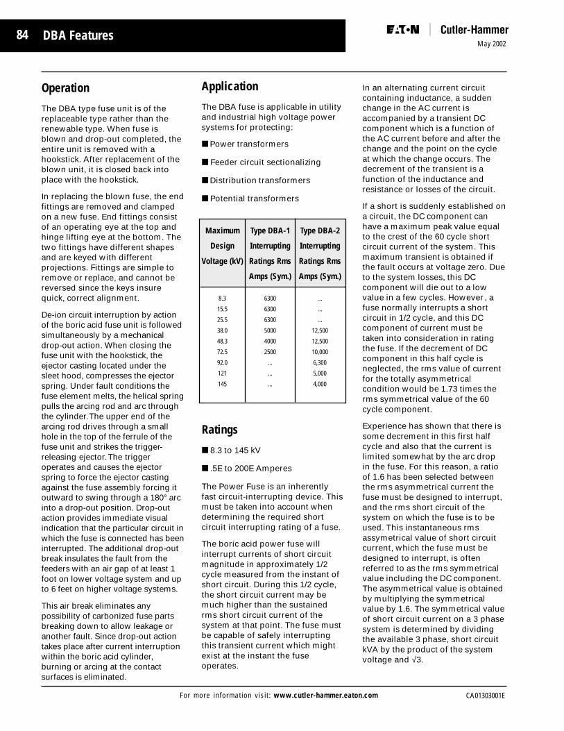
84May 2002
CA01303001EFor more information visit: www.cutler-hammer.eaton.com
DBA Features
Operation
The DBA type fuse unit is of thereplaceable type rather than therenewable type. When fuse isblown and drop-out completed, theentire unit is removed with ahookstick. After replacement of theblown unit, it is closed back intoplace with the hookstick.
In replacing the blown fuse, the endfittings are removed and clampedon a new fuse. End fittings consistof an operating eye at the top andhinge lifting eye at the bottom. Thetwo fittings have different shapesand are keyed with differentprojections. Fittings are simple toremove or replace, and cannot bereversed since the keys insurequick, correct alignment.
De-ion circuit interruption by actionof the boric acid fuse unit is followedsimultaneously by a mechanicaldrop-out action. When closing thefuse unit with the hookstick, theejector casting located under thesleet hood, compresses the ejectorspring. Under fault conditions thefuse element melts, the helical springpulls the arcing rod and arc throughthe cylinder. The upper end of thearcing rod drives through a smallhole in the top of the ferrule of thefuse unit and strikes the trigger-releasing ejector. The triggeroperates and causes the ejectorspring to force the ejector castingagainst the fuse assembly forcing itoutward to swing through a 180° arcinto a drop-out position. Drop-outaction provides immediate visualindication that the particular circuit inwhich the fuse is connected has beeninterrupted. The additional drop-outbreak insulates the fault from thefeeders with an air gap of at least 1foot on lower voltage system and upto 6 feet on higher voltage systems.
This air break eliminates anypossibility of carbonized fuse partsbreaking down to allow leakage oranother fault. Since drop-out actiontakes place after current interruptionwithin the boric acid cylinder,burning or arcing at the contactsurfaces is eliminated.
Application
The DBA fuse is applicable in utilityand industrial high voltage powersystems for protecting:
■ Power transformers
■ Feeder circuit sectionalizing
■ Distribution transformers
■ Potential transformers
Ratings
■ 8.3 to 145 kV
■ .5E to 200E Amperes
The Power Fuse is an inherentlyfast circuit-interrupting device. Thismust be taken into account whendetermining the required shortcircuit interrupting rating of a fuse.
The boric acid power fuse willinterrupt currents of short circuitmagnitude in approximately 1/2cycle measured from the instant ofshort circuit. During this 1/2 cycle,the short circuit current may bemuch higher than the sustainedrms short circuit current of thesystem at that point. The fuse mustbe capable of safely interruptingthis transient current which mightexist at the instant the fuseoperates.
In an alternating current circuitcontaining inductance, a suddenchange in the AC current isaccompanied by a transient DCcomponent which is a function ofthe AC current before and after thechange and the point on the cycleat which the change occurs. Thedecrement of the transient is afunction of the inductance andresistance or losses of the circuit.
If a short is suddenly established ona circuit, the DC component canhave a maximum peak value equalto the crest of the 60 cycle shortcircuit current of the system. Thismaximum transient is obtained ifthe fault occurs at voltage zero. Dueto the system losses, this DCcomponent will die out to a lowvalue in a few cycles. However , afuse normally interrupts a shortcircuit in 1/2 cycle, and this DCcomponent of current must betaken into consideration in ratingthe fuse. If the decrement of DCcomponent in this half cycle isneglected, the rms value of currentfor the totally asymmetricalcondition would be 1.73 times therms symmetrical value of the 60cycle component.
Experience has shown that there issome decrement in this first halfcycle and also that the current islimited somewhat by the arc dropin the fuse. For this reason, a ratioof 1.6 has been selected betweenthe rms asymmetrical current thefuse must be designed to interrupt,and the rms short circuit of thesystem on which the fuse is to beused. This instantaneous rmsassymetrical value of short circuitcurrent, which the fuse must bedesigned to interrupt, is oftenreferred to as the rms symmetricalvalue including the DC component.The asymmetrical value is obtainedby multiplying the symmetricalvalue by 1.6. The symmetrical valueof short circuit current on a 3 phasesystem is determined by dividingthe available 3 phase, short circuitkVA by the product of the systemvoltage and √3.
Maximum Type DBA-1 Type DBA-2
Design Interrupting Interrupting
Voltage (kV) Ratings Rms Ratings Rms
Amps (Sym.) Amps (Sym.)
8.3 6300 ...
15.5 6300 ...
25.5 6300 ...
38.0 5000 12,500
48.3 4000 12,500
72.5 2500 10,000
92.0 ... 6,300
121 ... 5,000
145 ... 4,000

85
CA01303001E
May 2002
For more information visit: www.cutler-hammer.eaton.com
DBA Installation
Instructions for Type DBAFuse Units 8.3 kV to 145 kV
Installation of Replacement Fuses
DBA Fuse units are available in twoclassifications, DBA-1 and DBA-2and are used for utility-typeapplications from 8.3 kV through145 kV.
Remove fuses from all three phasesand replace with new or testedunits. Fuses having been involvedin a fault but not blown should betested by resistance measurementsto ascertain that they are suitablefor continued service. Resistancelimits are available on request.
Prior to installation, it is advisableto check the functioning of themounting as follows:
1. Remove fuse fittings from hingecasting (Fig. 15) and mount on asuitable fuse unit as shownin Fig. 13.
2. Check gauging distance “S”between center of guide pin inlatch housing and bottom ofsocket in hinge casting asillustrated in Fig. 14. Dimension“S” must measure the same onboth sides of the mounting. Ifdimension “S” is found to beincorrect, adjust it by utilizing theclearances provided in the bolt
Figure 13: Fuse Unit with Fittings
kV DBA-1 DBA-2
7.2 13.5 ...15 17 ...23 21.5 ...
34.5 28.5 28.1346 34 336369 43.88 43.6392 ... 52
115 ... 62138 ... 72
holes (Fig. 16).
3. Put the suitable fuse unitequipped with fittings in themounting. Check operation oflatch assembly by closing andopening the fuse as shownin Fig. 17.
DBA-1 fuses up to 69 kV as well asDBA-2 fuses up to 46 kV can belifted into the hinge casting bymeans of conventional all-purposehooksticks. For lifting heavier fusesinto the hinge, a hookstick aboutone foot shorter than the distancefrom ground level to the fuse hingeis recommended. This hookstickshould be held approximatelyvertical as shown in Fig. 17. For theclosing-in or disconnectingoperation, a hookstick of at leastfour foot greater length should beemployed. Insert the hookstick pininto the eye of the fuse fitting fromthe right-hand side and have it forman angle of at least 35º with thefuse.
Fuse should be closed in with asharp thrust. A similar impact-likepull is required to open the fuse.After the latch contacts haveparted, the fuse may be allowed todisengage itself from the hookstickand drop out in a normal manner.
Maintenance
General maintenance instructionsare published in the IEEE StandardC-37.48-1973. Inspection of thefuse mounting should includechecking the gauge distance “S”(Fig. 14) and the operation of thelatch mechanism.
LOWEREYE
CASTING
LOCATINGPIN
UPPEREYE
CASTING
LOCATINGPIN
NAMEPLATE
CLAMPRING
FUSEUNIT A

86May 2002
CA01303001EFor more information visit: www.cutler-hammer.eaton.com
DBA Installation
Figure 15: Hinge Assembly
Figure 14: Insulator Spacing
Type Dimensions Voltage Rating (K.V.)
7.2 15 23 34.5 46 69 92 115 138DBA-1 C 13.63 17.13 21.63 28.63 34.13 44 __ __ __
S 15.25 18.75 23.25 30.25 35.75 45.63 __ __ __
DBA-2 C __ __ __ 27.88 33.38 43.38 51.75 61.75 71.75
(B) DBA-2 (C) DBA-2
34.5 to 69 kV 92 to 138 kV
7.2 to 46 kV 69 kV 92 to 138 kV

87
CA01303001E
May 2002
For more information visit: www.cutler-hammer.eaton.com
DBA Installation
Figure 17: Hookstick Operation
Figure 16: Spacer Adjustment

88May 2002
CA01303001EFor more information visit: www.cutler-hammer.eaton.com
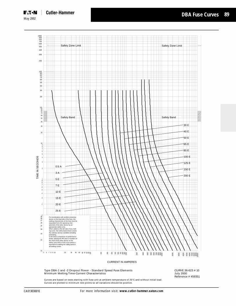
89
CA01303001E
May 2002
For more information visit: www.cutler-hammer.eaton.com
DBA Fuse Curves
Type DBA-1 and -2 Dropout Power - Standard Speed Fuse Elements CURVE 36-623 # 10Minimum Melting Time-Current Characteristics July 2000
Reference # 459351Curves are based on tests starting with fuse unit at ambient temperature of 25°C and without initial load.Curves are plotted to minimum test points so all variations should be positive.
TIM
E IN
SE
CO
ND
S10000
9000800070006000
5000
4000
3000
2000
1000900800700600
500
400
300
200
10090807060
50
40
30
20
109876
5
4
3
2
1.9.8.7.6
.5
.4
.3
.2
.1.09.08.07.06
.05
.04
.03
.02
.01
CURRENT IN AMPERES
1000
0090
000
8000
070
000
6000
0
5000
0
4000
0
3000
0
2000
0
1000
090
0080
0070
0060
00
5000
4000
3000
2000
100090
080
070
060
0
500
400
300
200
10090807060504030201098765
200 E
150 E
125 E
100 E
80 E
65 E
50 E
40 E
30 E
25 E
20 E
15 E
10 E
7 E
5 E
3 A
0.5 A
all melting curves.equivalent to adding the safety band to safety zone limits of this curve sheet is the chart of the other device on the charts, placing the RH and LH borders of In the direct comparison of performance preloading.the ordinary service variables including ing curve, the safety band shown covers When added at the left side of any melt-appropriate safety zone.acteristic of the other device by an separated from the operating char-melting characteristic of the fuse must be device on the load side of the fuse, the For coordination with another protective
Safety Zone Limit
Safety Band
Safety Zone Limit
Safety Band

90May 2002
CA01303001EFor more information visit: www.cutler-hammer.eaton.com
DBA Fuse Curves
Type DBA-1 Dropout Power - Standard Speed Fuse Elements CURVE 36-623 # 11Total Clearing Time-Current Characteristics - 2.4 to 23 kV July 2000
Reference # 459352Curves are based on tests starting with fuse unit at ambient temperature of 25°C and without initial load.Curves are plotted to maximum test points so all variations should be negative.
TIM
E IN
SE
CO
ND
S
100009000800070006000
5000
4000
3000
2000
1000900800700600
500
400
300
200
10090807060
50
40
30
20
109876
5
4
3
2
1.9.8.7.6
.5
.4
.3
.2
.1.09.08.07.06
.05
.04
.03
.02
.01
CURRENT IN AMPERES
1000
0090
000
8000
070
000
6000
0
5000
0
4000
0
3000
0
2000
0
1000
090
0080
0070
0060
00
5000
4000
3000
2000
100090
080
070
060
0
500
400
300
200
10090807060504030201098765
200 E
150 E
125 E
100 E
80 E
65 E
50 E
40 E
30 E
3 A
5 E
7 E
10 E
15 E
20 E
25 E
0.5 A

91
CA01303001E
May 2002
For more information visit: www.cutler-hammer.eaton.com
DBA Fuse Curves
Type DBA-1 and -2 Dropout Power - Standard Speed Fuse Elements CURVE 36-623 # 12Total Clearing Time-Current Characteristics - 34.5 to 69 kV July 2000
Reference # 459353Curves are based on tests starting with fuse unit at ambient temperature of 25°C and without initial load.Curves are plotted to maximum test points so all variations should be negative.
TIM
E IN
SE
CO
ND
S
100009000800070006000
5000
4000
3000
2000
1000900800700600
500
400
300
200
10090807060
50
40
30
20
109876
5
4
3
2
1.9.8.7.6
.5
.4
.3
.2
.1.09.08.07.06
.05
.04
.03
.02
.01
CURRENT IN AMPERES
1000
0090
000
8000
070
000
6000
0
5000
0
4000
0
3000
0
2000
0
1000
090
0080
0070
0060
00
5000
4000
3000
2000
100090
080
070
060
0
500
400
300
200
10090807060504030201098765
200 E
150 E
125 E
100 E
80 E
65 E
50 E
40 E
30 E
3 A
5 E
7 E
10 E
15 E
20 E
25 E
0.5 A

92May 2002
CA01303001EFor more information visit: www.cutler-hammer.eaton.com
DBA Fuse Curves
Type DBA- -2 Dropout Power - Standard Speed Fuse Elements CURVE 36-623 # 13Total Clearing Time-Current Characteristics - 92 to 138 kV July 2000
Reference # 459354Curves are based on tests starting with fuse unit at ambient temperature of 25°C and without initial load.Curves are plotted to maximum test points so all variations should be negative.
TIM
E IN
SE
CO
ND
S
100009000800070006000
5000
4000
3000
2000
1000900800700600
500
400
300
200
10090807060
50
40
30
20
109876
5
4
3
2
1.9.8.7.6
.5
.4
.3
.2
.1.09.08.07.06
.05
.04
.03
.02
.01
CURRENT IN AMPERES
1000
0090
000
8000
070
000
6000
0
5000
0
4000
0
3000
0
2000
0
1000
090
0080
0070
0060
00
5000
4000
3000
2000
100090
080
070
060
0
500
400
300
200
10090807060504030201098765
200 E
150 E
125 E
100 E
80 E
65 E
50 E
40 E
30 E
5 E
7 E
10 E
15 E
20 E
25 E

93
CA01303001E
May 2002
For more information visit: www.cutler-hammer.eaton.com
DBA Catalog Numbers and Information
Type DBA Expulsion Fuses for Use Indoors or Outdoors
Ratin
g A
mpe
res
Curv
eRe
fere
nce
3 6-6
2 3
Cata
log
Num
ber
App
roxi
mat
eSh
ippi
ngW
eigh
t
Type DBA-1 Fuse Refills
8.3 kV Max (7.2 kV Nominal)
0.5E 8DBA1-.5E3E 8DBA1-3E5E 8DBA1-5E7E 8DBA1-7E
10E 8DBA1-10E15E 8DBA1-15E20E 8DBA1-20E25E 8DBA1-25E30E 8DBA1-30E (10, 11) 2.140E 8DBA1-40E50E 8DBA1-50E65E 8DBA1-65E80E 8DBA1-80E
100E 8DBA1-100E125E 8DBA1-125E150E 8DBA1-150E200E 8DBA1-200E
15.5 kV Max (14.4 kV Nominal)
0.5E 15DBA1-.5E3E 15DBA1-3E5E 15DBA1-5E7E 15DBA1-7E
10E 15DBA1-10E15E 15DBA1-15E20E 15DBA1-20E25E 15DBA1-25E30E 15DBA1-30E (10, 11) 2.140E 15DBA1-40E50E 15DBA1-50E65E 15DBA1-65E80E 15DBA1-80E
100E 15DBA1-100E125E 15DBA1-125E150E 15DBA1-150E200E 15DBA1-200E
25 kV Max (23 kV Nominal)
0.5E 25DBA1-.5E3E 25DBA1-3E5E 25DBA1-5E7E 25DBA1-7E
10E 25DBA1-10E15E 25DBA1-15E20E 25DBA1-20E25E 25DBA1-25E30E 25DBA1-30E (10, 11) 3.140E 25DBA1-40E50E 25DBA1-50E65E 25DBA1-65E80E 25DBA1-80E
100E 25DBA1-100E125E 25DBA1-125E150E 25DBA1-150E200E 25DBA1-200E
DBA - 1 Fuse Units DBA - 1 Fuse Units
Ratin
g A
mpe
res
Cata
log
Num
ber
App
roxi
mat
eSh
ippi
ngW
eigh
t
Type DBA-1 Fuse Refills
38 kV Max (34.5 kV Nominal)
0.5E 38DBA1-.5E3E 38DBA1-3E5E 38DBA1-5E7E 38DBA1-7E
10E 38DBA1-10E15E 38DBA1-15E20E 38DBA1-20E25E 38DBA1-25E30E 38DBA1-30E (10, 12) 4.240E 38DBA1-40E50E 38DBA1-50E65E 38DBA1-65E80E 38DBA1-80E
100E 38DBA1-100E125E 38DBA1-125E150E 38DBA1-150E200E 38DBA1-200E
48 kV Max (46 kV Nominal)
0.5E 48DBA1-.5E3E 48DBA1-3E5E 48DBA1-5E7E 48DBA1-7E
10E 48DBA1-10E15E 48DBA1-15E20E 48DBA1-20E25E 48DBA1-25E30E 48DBA1-30E (10, 12) 6.540E 48DBA1-40E50E 48DBA1-50E65E 48DBA1-65E80E 48DBA1-80E
100E 48DBA1-100E125E 48DBA1-125E150E 48DBA1-150E200E 48DBA1-200E
72 kV Max (69 kV Nominal)
0.5E 72DBA1-.5E3E 72DBA1-3E5E 72DBA1-5E7E 72DBA1-7E
10E 72DBA1-10E15E 72DBA1-15E20E 72DBA1-20E25E 72DBA1-25E30E 72DBA1-30E (10, 12) 7.140E 72DBA1-40E50E 72DBA1-50E65E 72DBA1-65E80E 72DBA1-80E
100E 72DBA1-100E`125E 72DBA1-125E150E 72DBA1-150E200E 72DBA1-200E
Curv
eRe
fere
nce
36-6
23

94May 2002
CA01303001EFor more information visit: www.cutler-hammer.eaton.com
DBA Catalog Numbers and Information
Type DBA Expulsion Fuses for Use Indoors or Outdoors
Ratin
g A
mpe
res
Curv
eRe
fere
nce
3 6-6
2 3
Cata
log
Num
ber
App
roxi
mat
eSh
ippi
ngW
eigh
t
DBA - 2 Fuse Units DBA - 2 Fuse Units
Ratin
g A
mpe
res
Curv
eRe
fere
nce
3 6-6
2 3
Cata
log
Num
ber
App
roxi
mat
eSh
ippi
ngW
eigh
t
Type DBA-2 Fuse Refills
38 kV Max (34.5 kV Nominal)
0.5E 38DBA2-.5E3E 38DBA2-3E5E 38DBA2-5E7E 38DBA2-7E
10E 38DBA2-10E15E 38DBA2-15E20E 38DBA2-20E25E 38DBA2-25E30E 38DBA2-30E (10,12) 8.040E 38DBA2-40E50E 38DBA2-50E65E 38DBA2-65E80E 38DBA2-80E
100E 38DBA2-100E125E 38DBA2-125E150E 38DBA2-150E200E 38DBA2-200E
48 kV Max (46 kV Nominal)
0.5E 48DBA2-.5E3E 48DBA2-3E5E 48DBA2-5E7E 48DBA2-7E
10E 48DBA2-10E15E 48DBA2-15E20E 48DBA2-20E25E 48DBA2-25E30E 48DBA2-30E (10, 12) 8.040E 48DBA2-40E50E 48DBA2-50E65E 48DBA2-65E80E 48DBA2-80E
100E 48DBA2-100E125E 48DBA2-125E150E 48DBA2-150E200E 48DBA2-200E
72 kV Max (69 kV Nominal)
0.5E 72DBA2-.5E3E 72DBA2-3E5E 72DBA2-5E7E 72DBA2-7E
10E 72DBA2-10E15E 72DBA2-15E20E 72DBA2-20E25E 72DBA2-25E30E 72DBA2-30E (10, 12) 16.040E 72DBA2-40E50E 72DBA2-50E65E 72DBA2-65E80E 72DBA2-80E
100E 72DBA2-100E125E 72DBA2-125E150E 72DBA2-150E200E 72DBA2-200E
Type DBA-2 Fuse Refills
92 kV Max (92 kV Nominal)
3E 92DBA2-3E5E 92DBA2-5E7E 92DBA2-7E
10E 92DBA2-10E15E 92DBA2-15E20E 92DBA2-20E25E 92DBA2-25E30E 92DBA2-30E40E 92DBA2-40E (10, 13) 16.050E 92DBA2-50E65E 92DBA2-65E80E 92DBA2-80E
100E 92DBA2-100E125E 92DBA2-125E150E 92DBA2-150E200E 92DBA2-200E
121 kV Max (115 kV Nominal)
3E 121DBA2-3E5E 121DBA2-5E7E 121DBA2-7E
10E 121DBA2-10E15E 121DBA2-15E20E 121DBA2-20E25E 121DBA2-25E30E 121DBA2-30E40E 121DBA2-40E (10, 13) 15.050E 121DBA2-50E65E 121DBA2-65E80E 121DBA2-80E
100E 121DBA2-100E125E 121DBA2-125E150E 121DBA2-150E200E 121DBA2-200E
145 kV Max (138 kV Nominal)
3E 145DBA2-3E5E 145DBA2-5E7E 145DBA2-7E
10E 145DBA2-10E15E 145DBA2-15E20E 145DBA2-20E25E 145DBA2-25E30E 145DBA2-30E (10, 13) 14.040E 145DBA2-40E50E 145DBA2-50E65E 145DBA2-65E80E 145DBA2-80E
100E 145DBA2-100E125E 145DBA2-125E150E 145DBA2-150E200 145DBA2-200E
95
CA01303001E
May 2002
For more information visit: www.cutler-hammer.eaton.com
Cross Reference Guides
CrossReferenceGuide

96May 2002
CA01303001EFor more information visit: www.cutler-hammer.eaton.com
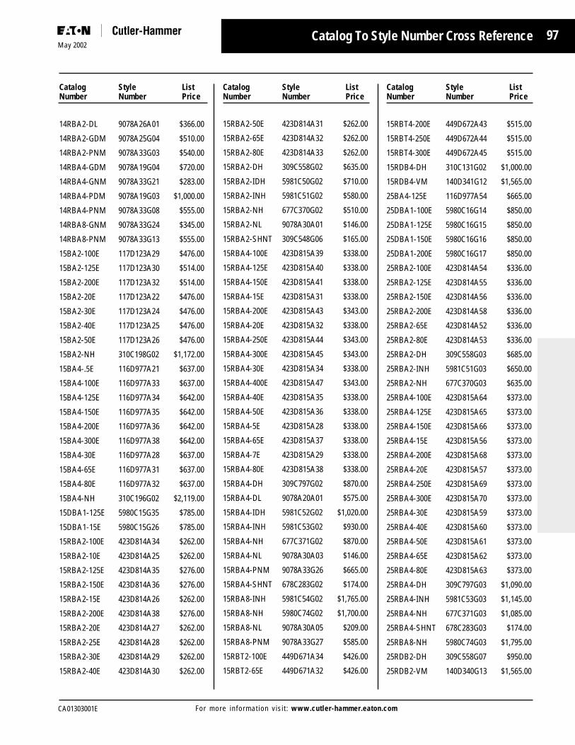
97
CA01303001E
May 2002
For more information visit: www.cutler-hammer.eaton.com
Catalog To Style Number Cross Reference
Catalog Style ListNumber Number Price
Catalog Style ListNumber Number Price
Catalog Style ListNumber Number Price
14RBA2-DL 9078A26A01 $366.00
14RBA2-GDM 9078A25G04 $510.00
14RBA2-PNM 9078A33G03 $540.00
14RBA4-GDM 9078A19G04 $720.00
14RBA4-GNM 9078A33G21 $283.00
14RBA4-PDM 9078A19G03 $1,000.00
14RBA4-PNM 9078A33G08 $555.00
14RBA8-GNM 9078A33G24 $345.00
14RBA8-PNM 9078A33G13 $555.00
15BA2-100E 117D123A29 $476.00
15BA2-125E 117D123A30 $514.00
15BA2-200E 117D123A32 $514.00
15BA2-20E 117D123A22 $476.00
15BA2-30E 117D123A24 $476.00
15BA2-40E 117D123A25 $476.00
15BA2-50E 117D123A26 $476.00
15BA2-NH 310C198G02 $1,172.00
15BA4-.5E 116D977A21 $637.00
15BA4-100E 116D977A33 $637.00
15BA4-125E 116D977A34 $642.00
15BA4-150E 116D977A35 $642.00
15BA4-200E 116D977A36 $642.00
15BA4-300E 116D977A38 $642.00
15BA4-30E 116D977A28 $637.00
15BA4-65E 116D977A31 $637.00
15BA4-80E 116D977A32 $637.00
15BA4-NH 310C196G02 $2,119.00
15DBA1-125E 5980C15G35 $785.00
15DBA1-15E 5980C15G26 $785.00
15RBA2-100E 423D814A34 $262.00
15RBA2-10E 423D814A25 $262.00
15RBA2-125E 423D814A35 $276.00
15RBA2-150E 423D814A36 $276.00
15RBA2-15E 423D814A26 $262.00
15RBA2-200E 423D814A38 $276.00
15RBA2-20E 423D814A27 $262.00
15RBA2-25E 423D814A28 $262.00
15RBA2-30E 423D814A29 $262.00
15RBA2-40E 423D814A30 $262.00
15RBA2-50E 423D814A31 $262.00
15RBA2-65E 423D814A32 $262.00
15RBA2-80E 423D814A33 $262.00
15RBA2-DH 309C558G02 $635.00
15RBA2-IDH 5981C50G02 $710.00
15RBA2-INH 5981C51G02 $580.00
15RBA2-NH 677C370G02 $510.00
15RBA2-NL 9078A30A01 $146.00
15RBA2-SHNT 309C548G06 $165.00
15RBA4-100E 423D815A39 $338.00
15RBA4-125E 423D815A40 $338.00
15RBA4-150E 423D815A41 $338.00
15RBA4-15E 423D815A31 $338.00
15RBA4-200E 423D815A43 $343.00
15RBA4-20E 423D815A32 $338.00
15RBA4-250E 423D815A44 $343.00
15RBA4-300E 423D815A45 $343.00
15RBA4-30E 423D815A34 $338.00
15RBA4-400E 423D815A47 $343.00
15RBA4-40E 423D815A35 $338.00
15RBA4-50E 423D815A36 $338.00
15RBA4-5E 423D815A28 $338.00
15RBA4-65E 423D815A37 $338.00
15RBA4-7E 423D815A29 $338.00
15RBA4-80E 423D815A38 $338.00
15RBA4-DH 309C797G02 $870.00
15RBA4-DL 9078A20A01 $575.00
15RBA4-IDH 5981C52G02 $1,020.00
15RBA4-INH 5981C53G02 $930.00
15RBA4-NH 677C371G02 $870.00
15RBA4-NL 9078A30A03 $146.00
15RBA4-PNM 9078A33G26 $665.00
15RBA4-SHNT 678C283G02 $174.00
15RBA8-INH 5981C54G02 $1,765.00
15RBA8-NH 5980C74G02 $1,700.00
15RBA8-NL 9078A30A05 $209.00
15RBA8-PNM 9078A33G27 $585.00
15RBT2-100E 449D671A34 $426.00
15RBT2-65E 449D671A32 $426.00
15RBT4-200E 449D672A43 $515.00
15RBT4-250E 449D672A44 $515.00
15RBT4-300E 449D672A45 $515.00
15RDB4-DH 310C131G02 $1,000.00
15RDB4-VM 140D341G12 $1,565.00
25BA4-125E 116D977A54 $665.00
25DBA1-100E 5980C16G14 $850.00
25DBA1-125E 5980C16G15 $850.00
25DBA1-150E 5980C16G16 $850.00
25DBA1-200E 5980C16G17 $850.00
25RBA2-100E 423D814A54 $336.00
25RBA2-125E 423D814A55 $336.00
25RBA2-150E 423D814A56 $336.00
25RBA2-200E 423D814A58 $336.00
25RBA2-65E 423D814A52 $336.00
25RBA2-80E 423D814A53 $336.00
25RBA2-DH 309C558G03 $685.00
25RBA2-INH 5981C51G03 $650.00
25RBA2-NH 677C370G03 $635.00
25RBA4-100E 423D815A64 $373.00
25RBA4-125E 423D815A65 $373.00
25RBA4-150E 423D815A66 $373.00
25RBA4-15E 423D815A56 $373.00
25RBA4-200E 423D815A68 $373.00
25RBA4-20E 423D815A57 $373.00
25RBA4-250E 423D815A69 $373.00
25RBA4-300E 423D815A70 $373.00
25RBA4-30E 423D815A59 $373.00
25RBA4-40E 423D815A60 $373.00
25RBA4-50E 423D815A61 $373.00
25RBA4-65E 423D815A62 $373.00
25RBA4-80E 423D815A63 $373.00
25RBA4-DH 309C797G03 $1,090.00
25RBA4-INH 5981C53G03 $1,145.00
25RBA4-NH 677C371G03 $1,085.00
25RBA4-SHNT 678C283G03 $174.00
25RBA8-NH 5980C74G03 $1,795.00
25RDB2-DH 309C558G07 $950.00
25RDB2-VM 140D340G13 $1,565.00

98May 2002
CA01303001EFor more information visit: www.cutler-hammer.eaton.com
Catalog To Style Number Cross Reference
Catalog Style ListNumber Number Price
Catalog Style ListNumber Number Price
Catalog Style ListNumber Number Price
25RDB4-DH 310C131G03 $1,090.00
38BA4-.5E 116D977A61 $680.00
38BA4-200E 116D977A76 $715.00
38BA4-40E 116D977A69 $680.00
38DBA1-100E 5980C16G34 $915.00
38DBA1-10E 5980C16G25 $915.00
38DBA1-125E 5980C16G35 $915.00
38DBA1-150E 5980C16G36 $915.00
38DBA1-200E 5980C16G37 $915.00
38DBA1-3E 505D420G04 $915.00
38DBA1-5E 5980C16G23 $915.00
38DBA1-7E 5980C16G24 $915.00
38DBA1-80E 5980C16G33 $915.00
38DBA2-125E 18A7330G25 $2,185.00
38DBA2-150E 18A7330G26 $2,185.00
38DBA2-3E 505D420G07 $2,185.00
38DBA2-5E 18A7330G13 $2,185.00
38RBA2-100E 423D814A74 $362.00
38RBA2-125E 423D814A75 $362.00
38RBA2-15E 423D814A66 $362.00
38RBA2-200E 423D814A78 $362.00
38RBA2-20E 423D814A67 $362.00
38RBA2-40E 423D814A70 $362.00
38RBA2-50E 423D814A71 $362.00
38RBA2-65E 423D814A72 $362.00
38RBA2-80E 423D814A73 $362.00
38RBA2-DH 309C558G04 $685.00
38RBA2-DL 9078A26A02 $385.00
38RBA2-INH 5981C51G04 $735.00
38RBA2-NH 677C370G04 $675.00
38RBA2-NL 9078A30A02 $230.00
38RBA2-PNM 9078A33G05 $1,105.00
38RBA4-100E 423D815A89 $399.00
38RBA4-125E 423D815A90 $399.00
38RBA4-150E 423D815A91 $399.00
38RBA4-200E 423D815A93 $399.00
38RBA4-20E 423D815A82 $399.00
38RBA4-250E 423D815A94 $399.00
38RBA4-300E 423D815A95 $399.00
38RBA4-40E 423D815A85 $399.00
38RBA4-50E 423D815A86 $399.00
38RBA4-5E 423D815A78 $399.00
38RBA4-65E 423D815A87 $399.00
38RBA4-80E 423D815A88 $399.00
38RBA4-DH 309C797G04 $1,210.00
38RBA4-DL 9078A20A02 $535.00
38RBA4-INH 5981C53G04 $1,275.00
38RBA4-NH 677C371G04 $1,210.00
38RBA4-NL 9078A30A04 $230.00
38RBA4-PDM 9078A19G07 $1,450.00
38RBA4-PNM 9078A33G10 $1,105.00
38RBA8-INH 5981C54G04 $1,945.00
38RBA8-NH 5980C74G04 $1,880.00
38RBA8-NL 9078A30A06 $241.00
38RBT4-100E 449D672A89 $680.00
38RBT4-125E 449D672A90 $680.00
38RBT4-150E 449D672A91 $301.24
38RDB4-DH 310C131G04 $1,210.00
38RDB4-SHNT 678C284G04 $371.00
38RDB4-VM 140D341G14 $1,900.00
48DBA1-.5E 5980C17G01 $1,040.00
48DBA1-100E 5980C17G14 $1,040.00
48DBA1-25E 5980C17G08 $1,040.00
48DBA1-40E 5980C17G10 $1,040.00
48DBA1-50E 5980C17G11 $1,040.00
48DBA1-65E 5980C17G12 $1,040.00
48DBA2-100E 18A7330G44 $2,480.00
48DBA2-150E 18A7330G46 “$2,480.00
48DBA2-200E 18A7330G47 $2,480.00
48DBA2-80E 18A7330G43 $2,480.00
5RBA2-PNM 9078A33G01 $463.00
5RBA4-GDM 9078A19G02 $700.00
72DBA1-.5E 5980C17G21 $1,125.00
72DBA1-100E 5980C17G34 $1,125.00
72DBA1-15E 5980C17G26 $1,125.00
72DBA1-20E 5980C17G27 $1,125.00
72DBA1-30E 5980C17G29 $1,125.00
72DBA1-40E 5980C17G30 $1,125.00
72DBA1-50E 5980C17G31 $1,125.00
72DBA1-5E 5980C17G23 $1,125.00
72DBA1-65E 5980C17G32 $1,125.00
72DBA2-.5E 22A6782G06 $2,825.00
72DBA2-15E 11A8127G05 $2,825.00
72DBA2-65E 11A8127G11 $2,825.00
8BA2-100E 117D123A13 $437.00
8BA2-125E 117D123A14 $476.00
8BA2-150E 117D123A15 $476.00
8BA2-15E 117D123A05 $437.00
8BA2-200E 117D123A16 $476.00
8BA2-25E 117D123A07 $437.00
8BA2-30E 117D123A08 $437.00
8BA2-50E 117D123A10 $437.00
8BA2-5E 117D123A02 $437.00
8BA2-65E 117D123A11 $437.00
8BA2-80E 117D123A12 $437.00
8BA2-MDH 117D122G01 $963.00
8BA4-200E 116D977A16 $637.00
8BA4-250E 116D977A17 $637.00
8BA4-300E 116D977A18 $637.00
8BA4-400E 116D977A19 $637.00
8BA4-65E 116D977A11 $599.00
8BA4-80E 116D977A12 $599.00
8BA4-DH 676C880G01 $1,573.00
8BA8-NH 677C605G01 $2,964.00
8RBA2-100E 423D814A14 $250.00
8RBA2-125E 423D814A15 $262.00
8RBA2-150E 423D814A16 $262.00
8RBA2-200E 423D814A18 $262.00
8RBA2-30E 423D814A09 $250.00
8RBA2-40E 423D814A10 $250.00
8RBA2-50E 423D814A11 $250.00
8RBA2-65E 423D814A12 $250.00
8RBA2-80E 423D814A13 $250.00
8RBA2-DH 309C558G01 $635.00
8RBA2-GDM 9078A25G09 $510.00
8RBA2-GNM 9078A33G17 $292.00
8RBA2-INH 5981C51G01 $550.00

99
CA01303001E
May 2002
For more information visit: www.cutler-hammer.eaton.com
Catalog Style ListNumber Number Price
Catalog Style ListNumber Number Price
Catalog To Style Number Cross Reference
8RBA2-NH 677C370G01 $417.00
8RBA4-100E 423D815A14 $336.00
8RBA4-125E 423D815A15 $336.00
8RBA4-150E 423D815A16 $336.00
8RBA4-200E 423D815A18 $336.00
8RBA4-250E 423D815A19 $336.00
8RBA4-300E 423D815A20 $336.00
8RBA4-400E 423D815A22 $336.00
8RBA4-40E 423D815A10 $336.00
8RBA4-50E 423D815A11 $336.00
8RBA4-80E 423D815A13 $336.00
8RBA4-DH 309C797G01 $835.00
8RBA4-GDM 9078A19G09 $720.00
8RBA4-IDH 5981C52G01 $900.00
8RBA4-INH 5981C53G01 $715.00
8RBA4-NH 677C371G01 $650.00
8RBA8-INH 5981C54G01 $1,675.00
8RBA8-NH 5980C74G01 $1,615.00
8RBT4-400E 449D672A21 $500.00
8RDB4-DH 310C131G01 $995.00
8RDB4-SHNT 678C284G01 $371.00
8RDB4-VM 140D341G11 $1,545.00
DBU17-3K 5981C75G01 $90.00
DBU17-6K 5981C75G02 $90.00
DBU17-8K 5981C75G03 $90.00
DBU17-10K 5981C75G04 $90.00
DBU17-12K 5981C75G05 $90.00
DBU17-15K 5981C75G06 $90.00
DBU17-20K 5981C75G07 $90.00
DBU17-25K 5981C75G08 $90.00
DBU17-30K 5981C75G09 $90.00
DBU17-40K 5981C75G10 $90.00
DBU17-50K 5981C75G11 $90.00
DBU17-65K 5981C75G12 $90.00
DBU17-80K 5981C75G13 $90.00
DBU17-100K 5981C75G14 $90.00
DBU17-140K 5981C75G15 $90.00
DBU17-200K 5981C75G16 $90.00
DBU17-5E 5981C76G01 $90.00
DBU17-7E 5981C76G02 $90.00
DBU17-10E 5981C76G03 $90.00
DBU17-13E 5981C76G04 $90.00
DBU17-15E 5981C76G05 $90.00
DBU17-20E 5981C76G06 $90.00
DBU17-25E 5981C76G07 $90.00
DBU17-30E 5981C76G08 $90.00
DBU17-40E 5981C76G09 $90.00
DBU17-50E 5981C76G10 $90.00
DBU17-65E 5981C76G11 $90.00
DBU17-80E 5981C76G12 $90.00
DBU17-100E 5981C76G13 $90.00
DBU17-125E 5981C76G14 $90.00
DBU17-150E 5981C76G15 $90.00
DBU17-175E 5981C76G16 $90.00
DBU17-200E 5981C76G17 $90.00
DBU17-15SE 5981C77G01 $90.00
DBU17-20SE 5981C77G02 $90.00
DBU17-25SE 5981C77G03 $90.00
DBU17-30SE 5981C77G04 $90.00
DBU17-40SE 5981C77G05 $90.00
DBU17-50SE 5981C77G06 $90.00
DBU17-65SE 5981C77G07 $90.00
DBU17-80SE 5981C77G08 $90.00
DBU17-100SE 5981C77G09 $90.00
DBU17-125SE 5981C77G10 $90.00
DBU17-150SE 5981C77G11 $90.00
DBU17-175SE 5981C77G12 $90.00
DBU17-200SE 5981C77G13 $90.00
DBU27-3K 5981C85G01 $93.50
DBU27-6K 5981C85G02 $93.50
DBU27-8K 5981C85G03 $93.50
DBU27-10K 5981C85G04 $93.50
DBU27-12K 5981C85G05 $93.50
DBU27-15K 5981C85G06 $93.50
DBU27-20K 5981C85G07 $93.50
DBU27-25K 5981C85G08 $93.50
DBU27-30K 5981C85G09 $93.50
DBU27-40K 5981C85G10 $93.50
DBU27-50K 5981C85G11 $93.50
DBU27-65K 5981C85G12 $93.50
DBU27-80K 5981C85G13 $93.50
DBU27-100K 5981C85G14 $93.50
DBU27-140K 5981C85G15 $93.50
DBU27-200K 5981C85G16 $93.50
DBU27-5E 5981C86G01 $93.50
DBU27-7E 5981C86G02 $93.50
DBU27-10E 5981C86G03 $93.50
DBU27-13E 5981C86G04 $93.50
DBU27-15E 5981C86G05 $93.50
DBU27-20E 5981C86G06 $93.50
DBU27-25E 5981C86G07 $93.50
DBU27-30E 5981C86G08 $93.50
DBU27-40E 5981C86G09 $93.50
DBU27-50E 5981C86G10 $93.50
DBU27-65E 5981C86G11 $93.50
DBU27-80E 5981C86G12 $93.50
DBU27-100E 5981C86G13 $93.50
DBU27-125E 5981C86G14 $93.50
DBU27-150E 5981C86G15 $93.50
DBU27-175E 5981C86G16 $93.50
DBU27-200E 5981C86G17 $93.50
DBU27-15SE 5981C87G01 $93.50
DBU27-20SE 5981C87G02 $93.50
DBU27-25SE 5981C87G03 $93.50
DBU27-30SE 5981C87G04 $93.50
DBU27-40SE 5981C87G05 $93.50
DBU27-50SE 5981C87G06 $93.50
DBU27-65SE 5981C87G07 $93.50
DBU27-80SE 5981C87G08 $93.50
DBU27-100SE 5981C87G09 $93.50
DBU27-125SE 5981C87G10 $93.50
DBU27-150SE 5981C87G11 $93.50
DBU27-175SE 5981C87G12 $93.50
DBU27-200SE 5981C87G13 $93.50
DBU38-3K 5981C95G01 $102.50
DBU38-6K 5981C95G02 $102.50
DBU38-8K 5981C95G03 $102.50
Catalog Style ListNumber Number Price

100May 2002
CA01303001EFor more information visit: www.cutler-hammer.eaton.com
DBU38-10K 5981C95G04 $102.50
DBU38-12K 5981C95G05 $102.50
DBU38-15K 5981C95G06 $102.50
DBU38-20K 5981C95G07 $102.50
DBU38-25K 5981C95G08 $102.50
DBU38-30K 5981C95G09 $102.50
DBU38-40K 5981C95G10 $102.50
DBU38-50K 5981C95G11 $102.50
DBU38-65K 5981C95G12 $102.50
DBU38-80K 5981C95G13 $102.50
DBU38-100K 5981C95G14 $102.50
DBU38-140K 5981C95G15 $102.50
DBU38-200K 5981C95G16 $102.50
DBU38-5E 5981C96G01 $102.50
DBU38-7E 5981C96G02 $102.50
DBU38-10E 5981C96G03 $102.50
DBU38-13E 5981C96G04 $102.50
DBU38-15E 5981C96G05 $102.50
DBU38-20E 5981C96G06 $102.50
DBU38-25E 5981C96G07 $102.50
DBU38-30E 5981C96G08 $102.50
DBU38-40E 5981C96G09 $102.50
DBU38-50E 5981C96G10 $102.50
DBU38-65E 5981C96G11 $102.50
DBU38-80E 5981C96G12 $102.50
DBU38-100E 5981C96G13 $102.50
DBU38-125E 5981C96G14 $102.50
DBU38-150E 5981C96G15 $102.50
DBU38-175E 5981C96G16 $102.50
DBU38-200E 5981C96G17 $102.50
DBU38-15SE 5981C97G01 $102.50
DBU38-20SE 5981C97G02 $102.50
DBU38-25SE 5981C97G03 $102.50
DBU38-30SE 5981C97G04 $102.50
DBU38-40SE 5981C97G05 $102.50
DBU38-50SE 5981C97G06 $102.50
DBU38-65SE 5981C97G07 $102.50
DBU38-80SE 5981C97G08 $102.50
DBU38-100SE 5981C97G09 $102.50
DBU38-125SE 5981C97G10 $102.50
DBU38-150SE 5981C97G11 $102.50
DBU38-175SE 5981C97G12 $102.50
DBU38-200SE 5981C97G13 $102.50
DBU-EFID 7187A11G01 $182.35
DBU-EFOD 7187A11G02 $66.55
DBU-MFLR 5981C69G01 $126.70
RBA2-COND 310C197G03 $198.00
RBA2-FLTR 309C024G03 $194.00
RBA4-COND 310C197G04 $333.00
RBA4-FLTR 591C607G01 $286.00
RBA4-FLTR-HC 591C607G02 $481.00
RBA4-IND 5980C29G02 $163.00
Catalog Style ListNumber Number Price
Catalog Style ListNumber Number Price
Catalog To Style Number Cross Reference

101
CA01303001E
May 2002
For more information visit: www.cutler-hammer.eaton.com
Style Catalog ListNumber Number Price
Style Catalog ListNumber Number Price
Style to Catalog Number Cross Reference
116D977A11 8BA4-65E $599.00
116D977A12 8BA4-80E $599.00
116D977A16 8BA4-200E $637.00
116D977A17 8BA4-250E $637.00
116D977A18 8BA4-300E $637.00
116D977A19 8BA4-400E $637.00
116D977A21 15BA4-.5E $637.00
116D977A28 15BA4-30E $637.00
116D977A31 15BA4-65E $637.00
116D977A32 15BA4-80E $637.00
116D977A33 15BA4-100E $637.00
116D977A34 15BA4-125E $642.00
116D977A35 15BA4-150E $642.00
116D977A36 15BA4-200E $642.00
116D977A38 15BA4-300E $642.00
116D977A54 25BA4-125E $665.00
116D977A61 38BA4-.5E $680.00
116D977A69 38BA4-40E $680.00
116D977A76 38BA4-200E $715.00
117D122G01 8BA2-MDH $963.00
117D123A02 8BA2-5E $437.00
117D123A05 8BA2-15E $437.00
117D123A07 8BA2-25E $437.00
117D123A08 8BA2-30E $437.00
117D123A10 8BA2-50E $437.00
117D123A11 8BA2-65E $437.00
117D123A12 8BA2-80E $437.00
117D123A13 8BA2-100E $437.00
117D123A14 8BA2-125E $476.00
117D123A15 8BA2-150E $476.00
117D123A16 8BA2-200E $476.00
117D123A22 15BA2-20E $476.00
117D123A24 15BA2-30E $476.00
117D123A25 15BA2-40E $476.00
117D123A26 15BA2-50E $476.00
117D123A29 15BA2-100E $476.00
117D123A30 15BA2-125E $514.00
117D123A32 15BA2-200E $514.00
11A8127G05 72DBA2-15E $2,825.00
11A8127G11 72DBA2-65E $2,825.00
140D340G13 25RDB2-VM $1,565.00
140D341G11 8RDB4-VM $1,545.00
140D341G12 15RDB4-VM $1,565.00
140D341G14 38RDB4-VM $1,900.00
18A7330G13 38DBA2-5E $2,185.00
18A7330G25 38DBA2-125E $2,185.00
18A7330G26 38DBA2-150E $2,185.00
18A7330G43 48DBA2-80E $2,480.00
18A7330G44 48DBA2-100E $2,480.00
18A7330G46 48DBA2-150E $2,480.00
18A7330G47 48DBA2-200E $2,480.00
22A6782G06 72DBA2-.5E $2,825.00
309C024G03 RBA2-FLTR $194.00
309C548G06 15RBA2-SHNT $165.00
309C558G01 8RBA2-DH $635.00
309C558G02 15RBA2-DH $635.00
309C558G03 25RBA2-DH $685.00
309C558G04 38RBA2-DH $685.00
309C558G07 25RDB2-DH $950.00
309C797G01 8RBA4-DH $835.00
309C797G02 15RBA4-DH $870.00
309C797G03 25RBA4-DH $1,090.00
309C797G04 38RBA4-DH $1,210.00
310C131G01 8RDB4-DH $995.00
310C131G02 15RDB4-DH $1,000.00
310C131G03 25RDB4-DH $1,090.00
310C131G04 38RDB4-DH $1,210.00
310C196G02 15BA4-NH $2,119.00
310C197G03 RBA2-COND $198.00
310C197G04 RBA4-COND $333.00
310C198G02 15BA2-NH $1,172.00
423D814A09 8RBA2-30E $250.00
423D814A10 8RBA2-40E $250.00
423D814A11 8RBA2-50E $250.00
423D814A12 8RBA2-65E $250.00
423D814A13 8RBA2-80E $250.00
423D814A14 8RBA2-100E $250.00
423D814A15 8RBA2-125E $262.00
423D814A16 8RBA2-150E $262.00
423D814A18 8RBA2-200E $262.00
423D814A25 15RBA2-10E $262.00
423D814A26 15RBA2-15E $262.00
423D814A27 15RBA2-20E $262.00
423D814A28 15RBA2-25E $262.00
423D814A29 15RBA2-30E $262.00
423D814A30 15RBA2-40E $262.00
423D814A31 15RBA2-50E $262.00
423D814A32 15RBA2-65E $262.00
423D814A33 15RBA2-80E $262.00
423D814A34 15RBA2-100E $262.00
423D814A35 15RBA2-125E $276.00
423D814A36 15RBA2-150E $276.00
423D814A38 15RBA2-200E $276.00
423D814A52 25RBA2-65E $336.00
423D814A53 25RBA2-80E $336.00
423D814A54 25RBA2-100E $336.00
423D814A55 25RBA2-125E $336.00
423D814A56 25RBA2-150E $336.00
423D814A58 25RBA2-200E $336.00
423D814A66 38RBA2-15E $362.00
423D814A67 38RBA2-20E $362.00
423D814A70 38RBA2-40E $362.00
423D814A71 38RBA2-50E $362.00
423D814A72 38RBA2-65E $362.00
423D814A73 38RBA2-80E $362.00
423D814A74 38RBA2-100E $362.00
423D814A75 38RBA2-125E $362.00
423D814A78 38RBA2-200E $362.00
423D815A10 8RBA4-40E $336.00
423D815A11 8RBA4-50E $336.00
423D815A13 8RBA4-80E $336.00
423D815A14 8RBA4-100E $336.00
423D815A15 8RBA4-125E $336.00
423D815A16 8RBA4-150E $336.00
423D815A18 8RBA4-200E $336.00
423D815A19 8RBA4-250E $336.00
423D815A20 8RBA4-300E $336.00
Style Catalog ListNumber Number Price

102May 2002
CA01303001EFor more information visit: www.cutler-hammer.eaton.com
423D815A22 8RBA4-400E $336.00
423D815A28 15RBA4-5E $338.00
423D815A29 15RBA4-7E $338.00
423D815A31 15RBA4-15E $338.00
423D815A32 15RBA4-20E $338.00
423D815A34 15RBA4-30E $338.00
423D815A35 15RBA4-40E $338.00
423D815A36 15RBA4-50E $338.00
423D815A37 15RBA4-65E $338.00
423D815A38 15RBA4-80E $338.00
423D815A39 15RBA4-100E $338.00
423D815A40 15RBA4-125E $338.00
423D815A41 15RBA4-150E $338.00
423D815A43 15RBA4-200E $343.00
423D815A44 15RBA4-250E $343.00
423D815A45 15RBA4-300E $343.00
423D815A47 15RBA4-400E $343.00
423D815A56 25RBA4-15E $373.00
423D815A57 25RBA4-20E $373.00
423D815A59 25RBA4-30E $373.00
423D815A60 25RBA4-40E $373.00
423D815A61 25RBA4-50E $373.00
423D815A62 25RBA4-65E $373.00
423D815A63 25RBA4-80E $373.00
423D815A64 25RBA4-100E $373.00
423D815A65 25RBA4-125E $373.00
423D815A66 25RBA4-150E $373.00
423D815A68 25RBA4-200E $373.00
423D815A69 25RBA4-250E $373.00
423D815A70 25RBA4-300E $373.00
423D815A78 38RBA4-5E $399.00
423D815A82 38RBA4-20E $399.00
423D815A85 38RBA4-40E $399.00
423D815A86 38RBA4-50E $399.00
423D815A87 38RBA4-65E $399.00
423D815A88 38RBA4-80E $399.00
423D815A89 38RBA4-100E $399.00
423D815A90 38RBA4-125E $399.00
423D815A91 38RBA4-150E $399.00
423D815A93 38RBA4-200E $399.00
423D815A94 38RBA4-250E $399.00
423D815A95 38RBA4-300E $399.00
449D671A32 15RBT2-65E $426.00
449D671A34 15RBT2-100E $426.00
449D672A21 8RBT4-400E $500.00
449D672A43 15RBT4-200E $515.00
449D672A44 15RBT4-250E $515.00
449D672A45 15RBT4-300E $515.00
449D672A89 38RBT4-100E $680.00
449D672A90 38RBT4-125E $680.00
449D672A91 38RBT4-150E $301.24
505D420G04 38DBA1-3E $915.00
505D420G07 38DBA2-3E $2,185.00
591C607G01 RBA4-FLTR $286.00
591C607G02 RBA4-FLTR-HC $481.00
5980C15G26 15DBA1-15E $785.00
5980C15G35 15DBA1-125E $785.00
5980C16G14 25DBA1-100E $850.00
5980C16G15 25DBA1-125E $850.00
5980C16G16 25DBA1-150E $850.00
5980C16G17 25DBA1-200E $850.00
5980C16G23 38DBA1-5E $915.00
5980C16G24 38DBA1-7E $915.00
5980C16G25 38DBA1-10E $915.00
5980C16G33 38DBA1-80E $915.00
5980C16G34 38DBA1-100E $915.00
5980C16G35 38DBA1-125E $915.00
5980C16G36 38DBA1-150E $915.00
5980C16G37 38DBA1-200E $915.00
5980C17G01 48DBA1-.5E $1,040.00
5980C17G08 48DBA1-25E $1,040.00
5980C17G10 48DBA1-40E $1,040.00
5980C17G11 48DBA1-50E $1,040.00
5980C17G12 48DBA1-65E $1,040.00
5980C17G14 48DBA1-100E $1,040.00
5980C17G21 72DBA1-.5E $1,125.00
5980C17G23 72DBA1-5E $1,125.00
5980C17G26 72DBA1-15E $1,125.00
5980C17G27 72DBA1-20E $1,125.00
5980C17G29 72DBA1-30E $1,125.00
5980C17G30 72DBA1-40E $1,125.00
5980C17G31 72DBA1-50E $1,125.00
5980C17G32 72DBA1-65E $1,125.00
5980C17G34 72DBA1-100E $1,125.00
5980C29G02 RBA4-IND $163.00
5980C74G01 8RBA8-NH $1,615.00
5980C74G02 15RBA8-NH $1,700.00
5980C74G03 25RBA8-NH $1,795.00
5980C74G04 38RBA8-NH $1,880.00
5981C50G02 15RBA2-IDH $710.00
5981C51G01 8RBA2-INH $550.00
5981C51G02 15RBA2-INH $580.00
5981C51G03 25RBA2-INH $650.00
5981C51G04 38RBA2-INH $735.00
5981C52G01 8RBA4-IDH $900.00
5981C52G02 15RBA4-IDH $1,020.00
5981C53G01 8RBA4-INH $715.00
5981C53G02 15RBA4-INH $930.00
5981C53G03 25RBA4-INH $1,145.00
5981C53G04 38RBA4-INH $1,275.00
5981C54G01 8RBA8-INH $1,675.00
5981C54G02 15RBA8-INH $1,765.00
5981C54G04 38RBA8-INH $1,945.00
5981C69G01 DBU-MFLR $126.70
5981C75G01 DBU17-3K $90.00
5981C75G02 DBU17-6K $90.00
5981C75G03 DBU17-8K $90.00
5981C75G04 DBU17-10K $90.00
5981C75G05 DBU17-12K $90.00
5981C75G06 DBU17-15K $90.00
5981C75G07 DBU17-20K $90.00
5981C75G08 DBU17-25K $90.00
5981C75G09 DBU17-30K $90.00
5981C75G10 DBU17-40K $90.00
5981C75G11 DBU17-50K $90.00
5981C75G12 DBU17-65K $90.00
5981C75G13 DBU17-80K $90.00
Style Catalog ListNumber Number Price
Style Catalog ListNumber Number Price
Style to Catalog Number Cross Reference
Style Catalog ListNumber Number Price
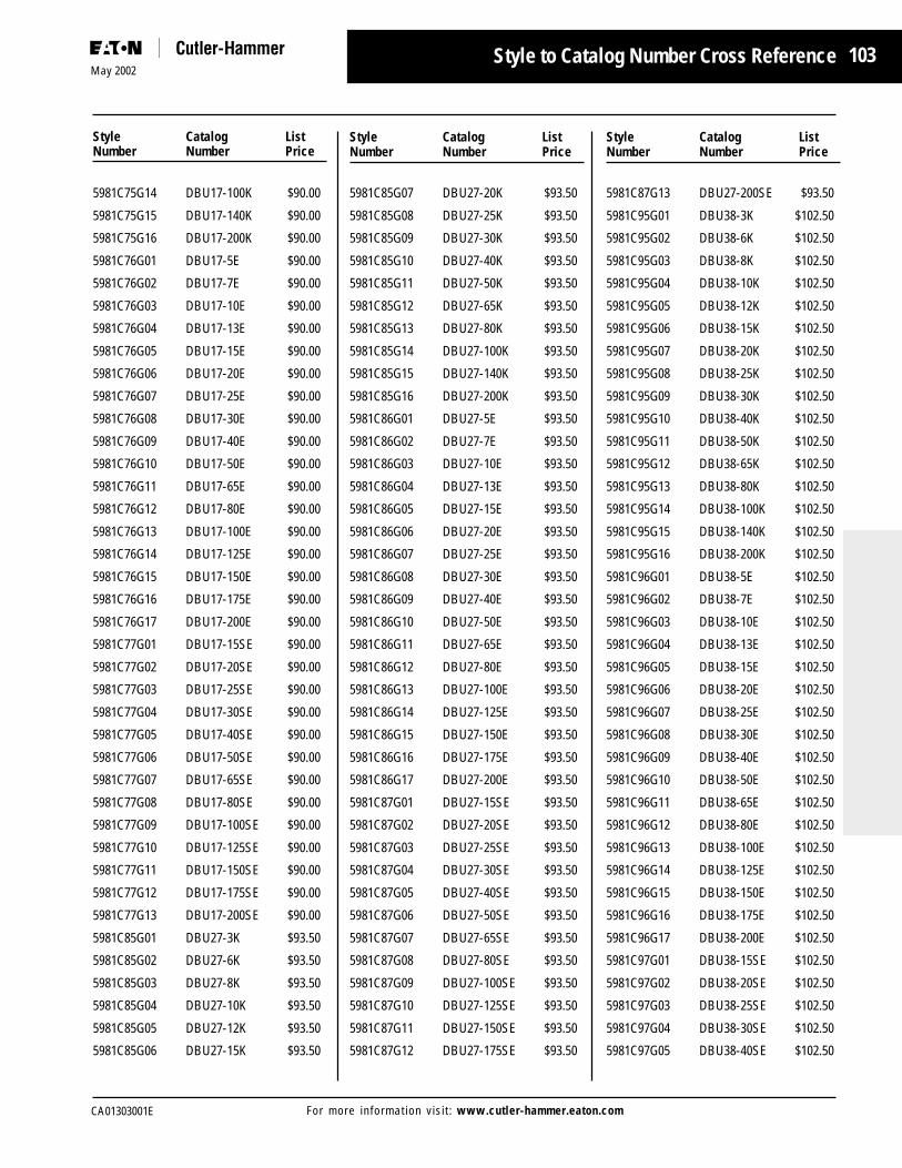
103
CA01303001E
May 2002
For more information visit: www.cutler-hammer.eaton.com
5981C75G14 DBU17-100K $90.00
5981C75G15 DBU17-140K $90.00
5981C75G16 DBU17-200K $90.00
5981C76G01 DBU17-5E $90.00
5981C76G02 DBU17-7E $90.00
5981C76G03 DBU17-10E $90.00
5981C76G04 DBU17-13E $90.00
5981C76G05 DBU17-15E $90.00
5981C76G06 DBU17-20E $90.00
5981C76G07 DBU17-25E $90.00
5981C76G08 DBU17-30E $90.00
5981C76G09 DBU17-40E $90.00
5981C76G10 DBU17-50E $90.00
5981C76G11 DBU17-65E $90.00
5981C76G12 DBU17-80E $90.00
5981C76G13 DBU17-100E $90.00
5981C76G14 DBU17-125E $90.00
5981C76G15 DBU17-150E $90.00
5981C76G16 DBU17-175E $90.00
5981C76G17 DBU17-200E $90.00
5981C77G01 DBU17-15SE $90.00
5981C77G02 DBU17-20SE $90.00
5981C77G03 DBU17-25SE $90.00
5981C77G04 DBU17-30SE $90.00
5981C77G05 DBU17-40SE $90.00
5981C77G06 DBU17-50SE $90.00
5981C77G07 DBU17-65SE $90.00
5981C77G08 DBU17-80SE $90.00
5981C77G09 DBU17-100SE $90.00
5981C77G10 DBU17-125SE $90.00
5981C77G11 DBU17-150SE $90.00
5981C77G12 DBU17-175SE $90.00
5981C77G13 DBU17-200SE $90.00
5981C85G01 DBU27-3K $93.50
5981C85G02 DBU27-6K $93.50
5981C85G03 DBU27-8K $93.50
5981C85G04 DBU27-10K $93.50
5981C85G05 DBU27-12K $93.50
5981C85G06 DBU27-15K $93.50
Style Catalog ListNumber Number Price
Style to Catalog Number Cross Reference
5981C85G07 DBU27-20K $93.50
5981C85G08 DBU27-25K $93.50
5981C85G09 DBU27-30K $93.50
5981C85G10 DBU27-40K $93.50
5981C85G11 DBU27-50K $93.50
5981C85G12 DBU27-65K $93.50
5981C85G13 DBU27-80K $93.50
5981C85G14 DBU27-100K $93.50
5981C85G15 DBU27-140K $93.50
5981C85G16 DBU27-200K $93.50
5981C86G01 DBU27-5E $93.50
5981C86G02 DBU27-7E $93.50
5981C86G03 DBU27-10E $93.50
5981C86G04 DBU27-13E $93.50
5981C86G05 DBU27-15E $93.50
5981C86G06 DBU27-20E $93.50
5981C86G07 DBU27-25E $93.50
5981C86G08 DBU27-30E $93.50
5981C86G09 DBU27-40E $93.50
5981C86G10 DBU27-50E $93.50
5981C86G11 DBU27-65E $93.50
5981C86G12 DBU27-80E $93.50
5981C86G13 DBU27-100E $93.50
5981C86G14 DBU27-125E $93.50
5981C86G15 DBU27-150E $93.50
5981C86G16 DBU27-175E $93.50
5981C86G17 DBU27-200E $93.50
5981C87G01 DBU27-15SE $93.50
5981C87G02 DBU27-20SE $93.50
5981C87G03 DBU27-25SE $93.50
5981C87G04 DBU27-30SE $93.50
5981C87G05 DBU27-40SE $93.50
5981C87G06 DBU27-50SE $93.50
5981C87G07 DBU27-65SE $93.50
5981C87G08 DBU27-80SE $93.50
5981C87G09 DBU27-100SE $93.50
5981C87G10 DBU27-125SE $93.50
5981C87G11 DBU27-150SE $93.50
5981C87G12 DBU27-175SE $93.50
5981C87G13 DBU27-200SE $93.50
5981C95G01 DBU38-3K $102.50
5981C95G02 DBU38-6K $102.50
5981C95G03 DBU38-8K $102.50
5981C95G04 DBU38-10K $102.50
5981C95G05 DBU38-12K $102.50
5981C95G06 DBU38-15K $102.50
5981C95G07 DBU38-20K $102.50
5981C95G08 DBU38-25K $102.50
5981C95G09 DBU38-30K $102.50
5981C95G10 DBU38-40K $102.50
5981C95G11 DBU38-50K $102.50
5981C95G12 DBU38-65K $102.50
5981C95G13 DBU38-80K $102.50
5981C95G14 DBU38-100K $102.50
5981C95G15 DBU38-140K $102.50
5981C95G16 DBU38-200K $102.50
5981C96G01 DBU38-5E $102.50
5981C96G02 DBU38-7E $102.50
5981C96G03 DBU38-10E $102.50
5981C96G04 DBU38-13E $102.50
5981C96G05 DBU38-15E $102.50
5981C96G06 DBU38-20E $102.50
5981C96G07 DBU38-25E $102.50
5981C96G08 DBU38-30E $102.50
5981C96G09 DBU38-40E $102.50
5981C96G10 DBU38-50E $102.50
5981C96G11 DBU38-65E $102.50
5981C96G12 DBU38-80E $102.50
5981C96G13 DBU38-100E $102.50
5981C96G14 DBU38-125E $102.50
5981C96G15 DBU38-150E $102.50
5981C96G16 DBU38-175E $102.50
5981C96G17 DBU38-200E $102.50
5981C97G01 DBU38-15SE $102.50
5981C97G02 DBU38-20SE $102.50
5981C97G03 DBU38-25SE $102.50
5981C97G04 DBU38-30SE $102.50
5981C97G05 DBU38-40SE $102.50
Style Catalog ListNumber Number Price
Style Catalog ListNumber Number Price

104May 2002
CA01303001EFor more information visit: www.cutler-hammer.eaton.com
5981C97G06 DBU38-50SE $102.50
5981C97G07 DBU38-65SE $102.50
5981C97G08 DBU38-80SE $102.50
5981C97G09 DBU38-100SE $102.50
5981C97G10 DBU38-125SE $102.50
5981C97G11 DBU38-150SE $102.50
5981C97G12 DBU38-175SE $102.50
5981C97G13 DBU38-200SE $102.50
676C880G01 8BA4-DH $1,573.00
677C370G01 8RBA2-NH $417.00
677C370G02 15RBA2-NH $510.00
677C370G03 25RBA2-NH $635.00
677C370G04 38RBA2-NH $675.00
677C371G01 8RBA4-NH $650.00
677C371G02 15RBA4-NH $870.00
677C371G03 25RBA4-NH $1,085.00
677C371G04 38RBA4-NH $1,210.00
677C605G01 8BA8-NH $2,964.00
678C283G02 15RBA4-SHNT $174.00
678C283G03 25RBA4-SHNT $174.00
678C284G01 8RDB4-SHNT $371.00
678C284G04 38RDB4-SHNT $371.00
7187A11G01 DBU-EFID $182.35
7187A11G02 DBU-EFOD $66.55
9078A19G02 5RBA4-GDM $700.00
9078A19G03 14RBA4-PDM $1,000.00
9078A19G04 14RBA4-GDM $720.00
9078A19G07 38RBA4-PDM $1,450.00
9078A19G09 8RBA4-GDM $720.00
9078A20A01 15RBA4-DL $575.00
9078A20A02 38RBA4-DL $535.00
9078A25G04 14RBA2-GDM $510.00
9078A25G09 8RBA2-GDM $510.00
9078A26A01 14RBA2-DL $366.00
9078A26A02 38RBA2-DL $385.00
9078A30A01 15RBA2-NL $146.00
9078A30A02 38RBA2-NL $230.00
9078A30A03 15RBA4-NL $146.00
9078A30A04 38RBA4-NL $230.00
9078A30A05 15RBA8-NL $209.00
9078A30A06 38RBA8-NL $241.00
9078A33G01 5RBA2-PNM $463.00
9078A33G03 14RBA2-PNM $540.00
9078A33G05 38RBA2-PNM $1,105.00
9078A33G08 14RBA4-PNM $555.00
9078A33G10 38RBA4-PNM $1,105.00
9078A33G13 14RBA8-PNM $555.00
9078A33G17 8RBA2-GNM $292.00
9078A33G21 14RBA4-GNM $283.00
9078A33G24 14RBA8-GNM $345.00
9078A33G26 15RBA4-PNM $665.00
9078A33G27 15RBA8-PNM $585.00
Style Catalog ListNumber Number Price
Style Catalog ListNumber Number Price
Style to Catalog Number Cross Reference

© 2002 Eaton CorporationAll Rights ReservedPrinted in USACA01303001E / CSS18743March 2002
Eaton CorporationCutler-Hammer business unit1000 Cherrington ParkwayMoon Township, PA 15108United Statestel: 1-800-525-2000www.cutler-hammer.eaton.com
Company InformationEaton’s Cutler-Hammer business is a worldwide leader providing customer-driven solutions. From powerdistribution and electrical control products to industrial automation, the Cutler-Hammer business utilizesadvanced product development, world-class manufacturing, and offers global engineering services andsupport. To learn more about Eaton’s innovative Cutler-Hammer products and solutions call 1-800-525-2000,for engineering services call 1-800-498-2678, or visit www.cutler-hammer.eaton.com.
Eaton is a global $7.3 billion diversified industrial manufacturer that is a leader in fluid power systems;electrical power quality, distribution and control; automotive engine air management and fuel economy;and intelligent truck systems for fuel economy and safety. Eaton has 49,000 employees and sells productsin more than 50 countries. For more information, visit www.eaton.com.