Embed Size (px)
Citation preview

www.siemens.com/energy
Catalog HG 11.42 · 2008
������� ��� ��� ��� ���
Medium-Voltage EquipmentSelection and Ordering Data

2 Siemens HG 11.42 · 2008
R-HG
11-1
72.ti
f
2
Siemens Vacuum Recloser 3AD

2
1
3
4
3Siemens HG 11.42 · 2008
Siemens VacuumRecloser 3AD
Medium-Voltage EquipmentCatalog HG 11.42 · 2008
© Siemens AG 2008
Contents Page
DescriptionGeneral
Switch unit
Controller, protection functions
Ambient conditions, altitude correction factorand number of operating cycles
Product range overview and scope of delivery
56
7
9
13
14
Product SelectionOrdering data and configuration example
Selection of primary ratings
Selection of controller
Selection of additional equipment
1516
17
20
24
Technical DataElectrical data, dimensions and weights:
Voltage level 12 kV
Voltage level 15.5 kV
Voltage level 27 kV
Voltage level 38 kV
27
28
28
29
29
AnnexInquiry form
Configuration instructions
Configuration aid
3334
35
Siemens Vacuum Recloser 3AD Contents
Foldout page

4 Siemens HG 11.42 · 2008
R-HG
11-3
00.ti
f
Siemens Vacuum Recloser 3AD

1
Siemens HG 11.42 · 2008 5
DescriptionContents
Vacuum recloser with cubicle and controller
R-HG
11-3
01.ti
f
Contents Page
Description
General
Switch unit:
Recloser principle
Design
Pole assemblies
Operating mechanism
Magnetic actuator
Mechanical lockout
Recloser cycle
Controller:
User interface
Protection functions
Communications
Protocols
Metering functions
Data records
Software
Standards
Ambient conditions
Altitude correction factor
Number of operating cycles
Product range overview
Scope of delivery
5
6
7
7
7
7
7
8
8
9
10
11
11
11
11
12
12
13
13
13
14
14
Siemens Vacuum Recloser 3AD

1
Siemens HG 11.42 · 20086
Siemens vacuum recloser 3AD
The switch unit is the primary part of the recloser. It islocated on top of the pole to switch the overhead line.It is permanently exposed to weather and environment.
As the heart of the recloser, the controller is located in acubicle at the bottom of the pole.
Switch unit Controller inside the cubicleR-
HG11
-302
.tif
R-HG
11-3
03.ti
f
DescriptionGeneral
3AD vacuum reclosers are outdoor circuit-breakersdesigned for frequent opening and reclosing in case oftemporary faults. They fulfill this task automatically bymonitoring the line and operating autonomously.
The recloser consists of two main components: Theswitch unit being the circuit-breaker and the controller asprotection and control unit. It is housed inside the controlcubicle.
Siemens Vacuum Recloser 3AD

1
Siemens HG 11.42 · 2008 7
Recloser principle
Reclosers are used in distribution systems of power supplycompanies (utilities). Like circuit-breakers they are capableof switching normal and fault currents. They are equippedwith sensors and a controller being the protection andcontrol device. In case of a line fault, they can break andmake several times, thus avoiding longer network interrup-tions due to temporary faults.
As outdoor devices they are normally pole-mounted andexposed to environment and weather. A recloser consists oftwo components: The switch unit (circuit-breaker) and thecontroller (inside the control cubicle), both connectedthrough a control cable.
Design
Switching operationThe vacuum switching technology, proven and fullydeveloped for more than 30 years, is the basis for thevacuum interrupters.
Pole assemblies
Each vacuum interrupter is embedded in an epoxy-resin polemade out of weather-proof cycloalyphatic resin. This enablesa small design as well as resistance against environmentaleffects. The vacuum interrupter is vertically mounted insidethe pole, providing a long service life. Each recloser is equip-ped with an integrated current transformer. For special pro-tection purposes, a resistive voltage sensor can also beincorporated in the pole. The accuracy achieved in this wayis much higher than that of capacitive dividers.
Operating mechanism
The pole assemblies of the recloser are directly mounted onthe operating mechanism housing. Besides the completekinematics, it also accommodates the position indicator anda mechanical operations counter. The operating mechanismhousing is made of mild steel with a special coating for out-door applications. Optionally, a stainless-steel housing isavailable.
The recloser is installed on the pole by means of a polemounting frame. Alternatively, the recloser can be mounteddirectly on a frame for pad-mounting in substations.
Magnetic actuator
The recloser is operated by a magnetic actuator enabling therecloser cycle, i.e. the high number of switching operationswithin a short period of time. The actuator is a bi-stablesystem, locked in the end positions by permanent magnets.If not in operation, the magnet coils do not consume anypower. The operating force is transmitted to all three polesthrough a mechanical coupling.
DescriptionSwitch unit
Siemens Vacuum Recloser 3AD
����
����
��
�
Structure of the switch unit
Switch unit – front view
Switch unit – rear view
R-HG
11-3
04.ti
fR-
HG11
-305
.tif

1
Siemens HG 11.42 · 20088
Siemens Vacuum Recloser 3ADDescriptionSwitch unit
Mechanical lockout
A mechanical lockout enables tripping independently on thecontroller. If this handle is pulled, the recloser opens and issimultaneously locked out electrically and mechanically. Thehandle stays extended, thus indicating the interlocked state.
To close the recloser again, the operating rod must first bepushed back to the operation position in order to release thelockout. Then the recloser can be closed electrically via thecontrol.
Recloser cycle
In case of a network fault, the recloser opens and reclosesseveral times. In case of temporary faults the automaticreclosing significantly reduces the loss of power supply.The recloser cycle is optimized accordingly:
• The first interruption of a fault is done quickly andinstantaneously, so that even the fuses in the system do notoperate. After approx. 300 ms (user settable), it reclosesback on.
• The second and third interruption has a definite or inverse-time delay. Thus, downstream fuses in the network have thechance to operate and isolate the affected network section,restoring normal operation in the remaining network. Thefollowing dead time is usually 2–10 s (user settable).
• The fourth (optional up to the fifth) interruption is fastagain and serves as a check. This for example utilizes thephysical effect that, when the short-circuit occurs, the linesmove due to the magnetic forces of the current, and foreignobjects are “shaken off”.
• If the fault still exists, the recloser turns to the lockout andcan only be closed from the operator panel or via SCADA.
Lock-out handle – pushed in(operational position)
Lock-out handle – pulled(open position)
R-HG
11-3
06.ti
fR-
HG11
-307
.tif
1
Siemens HG 11.42 · 2008 9
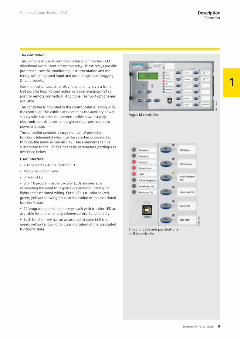
The controller
The Siemens Argus-M controller is based on the Argus-Mdirectional overcurrent protection relay. These relays provideprotection, control, monitoring, instrumentation and me-tering with integrated input and output logic, data logging& fault reports.
Communication access to relay functionality is via a frontUSB port for local PC connection or a rear electrical RS485port for remote connection. Additional rear port options areavailable.
The controller is mounted in the control cubicle. Along withthe controller, this cubicle also contains the auxiliary powersupply with batteries for uninterruptible power supply,electronic boards, fuses, and a general-purpose outlet topower a laptop.
The controller contains a large number of protectionfunctions (elements) which can be selected or deselectedthrough the menu driven display. These elements can becustomized to the utilities’ needs by parameters (settings) asdescribed below.
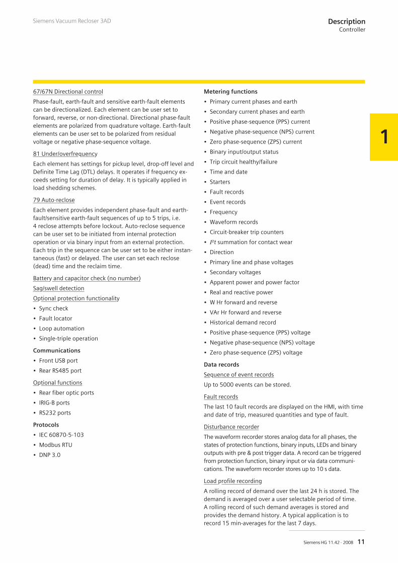
User interface
• 20-character x 4-line backlit LCD
• Menu navigation keys
• 3 fixed LEDs
• 8 or 16 programmable tri-color LEDs are availableeliminating the need for expensive panel-mounted pilotlights and associated wiring. Each LED is tri-colored (red,green, yellow) allowing for clear indication of the associatedfunction’s state.
• 12 programmable function keys each with tri-color LED areavailable for implementing scheme control functionality.
• Each function key has an associated tri-color LED (red,green, yellow) allowing for clear indication of the associatedfunction’s state.
DescriptionController
Siemens Vacuum Recloser 3AD
Argus-M controller
Tri-color LEDs and pushbuttonsof the controller
R-HG
11-3
08.ti
f
R-HG
11-3
09.ti
f

1
Siemens HG 11.42 · 200810
DescriptionController
Siemens Vacuum Recloser 3AD
Protection functions(in order of ANSI numbering)
37 Undercurrent
Each element has settings for pickup level and Definite TimeLag (DTL) delays. Operates if current falls below setting forduration of delay.
46BC Broken conductor/phase unbalance
Element has settings for pickup level and DTL delay. With thecircuit-breaker closed, if one or two of the line currents fallbelow setting, this could be due to a broken conductor.
46NPS Negative phase-sequence overcurrent
Each element has user settings for pickup level and InverseDefinite Minimum Time Lag (IDMTL) or DTL delay. It operatesif NPS current exceeds setting and delay. NPS current ele-ments can be used to detect unbalances on the system orremote earth faults when a delta-star transformer is incircuit.
49 Thermal overload
The thermal algorithm calculates the thermal states from themeasured currents and can be applied to lines, cables andtransformers. Outputs are available for thermal overload andthermal capacity.
50/51 Phase fault
50 INST (instantaneous)/DTL (Definite Time Lag) and51 IDMTL (Inverse Definite Minimum Time Lag)/DTL ele-ments provide overcurrent protection, each with indepen-dent settings for pickup current, time-multiplier (51) andtime delays. The user can select IEC or ANSI time currentcharacteristics. The IDMT stage has a user programmablereset characteristic, either DTL or shaped current/time resetcharacteristic to improve grading with electromechanicalprotection.
50G/51G/50N/51N Earth fault/sensitive earth fault
Earth-fault current is derived from the residual connection ofthe 3 integrated line CTs. 50 INST/DTL and 51 IDMTL/DTLelements provide overcurrent protection, each with indepen-dent settings for pickup current, time-multiplier (51) andtime delays. The user can select IEC or ANSI time currentcharacteristics. The IDMT stage has a user programmablereset characteristic, either DTL or shaped current/time resetcharacteristic to improve grading with electromechanicalprotection.
50BF Circuit-breaker fail
The circuit-breaker fail function is triggered from an internaltrip signal. Line currents are monitored following a trip signaland an output is issued if any current is still detected after aspecified time interval. This can be used to re-trip the CB orto back-trip an upstream CB. A second back-trip time delay isavailable to enable another stage to be utilized if required.
64H Restricted earth-fault scheme
The measured earth-fault input may be used in a 64H highimpedance restricted earth-fault scheme. Required externalseries stabilizing resistor and non-linear shunt resistor can besupplied.
74TC Trip-circuit supervision
The trip-circuit(s) can be monitored via binary inputs. Trip-circuit failure raises an HMI alarm and output(s).
81HBL2 Inrush restrain/second harmonic block
Where second harmonic current is detected (i.e. duringtransformer energization) user selectable elements can beblocked.
Cold load pickup
If a circuit-breaker is closed onto a “cold” load, i.e. one thathas not been powered for a prolonged period, this canimpose a higher than normal load-current demand on thesystem which could exceed normal settings. Theseconditions can exist for an extended period and must not beinterpreted as a fault. To allow optimum setting levels to beapplied for normal operation, the cold load pickup featurewill apply alternative settings for a limited period. The fea-ture resets when either the circuit-breaker has been closedfor a settable period, or if the current has been reducedbeneath a set level for a user set period.
27/59 Under/overvoltage
Each element has settings for pickup level, drop-off level andDefinite Time Lag (DTL) delays. It operates if voltage exceedssetting for duration of delay. It can be applied in load shed-ding schemes.
47 Negative phase-sequence overvoltage
Each element has settings for pickup level and Definite TimeLag (DTL) delays. It operates if NPS voltage exceeds settingfor duration of delay.
59N Neutral overvoltage
Each element has settings for pickup level and Definite TimeLag (DTL) delays. It operates if neutral voltage exceedssetting for duration of delay. Neutral overvoltage can beused to detect earth faults in high impedance earthed orisolated systems.
60CTS CT supervision
The CT supervision considers the presence of negativephase-sequence current, without an equivalent level ofnegative phase-sequence voltage, for a user set time as aCT failure. The element has user operate and delay settings.
1
Siemens HG 11.42 · 2008 11
DescriptionController
Siemens Vacuum Recloser 3AD
67/67N Directional control
Phase-fault, earth-fault and sensitive earth-fault elementscan be directionalized. Each element can be user set toforward, reverse, or non-directional. Directional phase-faultelements are polarized from quadrature voltage. Earth-faultelements can be user set to be polarized from residualvoltage or negative phase-sequence voltage.
81 Under/overfrequency
Each element has settings for pickup level, drop-off level andDefinite Time Lag (DTL) delays. It operates if frequency ex-ceeds setting for duration of delay. It is typically applied inload shedding schemes.
79 Auto-reclose
Each element provides independent phase-fault and earth-fault/sensitive earth-fault sequences of up to 5 trips, i.e.4 reclose attempts before lockout. Auto-reclose sequencecan be user set to be initiated from internal protectionoperation or via binary input from an external protection.Each trip in the sequence can be user set to be either instan-taneous (fast) or delayed. The user can set each reclose(dead) time and the reclaim time.
Battery and capacitor check (no number)
Sag/swell detection
Optional protection functionality
• Sync check
• Fault locator
• Loop automation
• Single-triple operation
Communications
• Front USB port
• Rear RS485 port
Optional functions
• Rear fiber optic ports
• IRIG-B ports
• RS232 ports
Protocols
• IEC 60870-5-103
• Modbus RTU
• DNP 3.0
Metering functions
• Primary current phases and earth
• Secondary current phases and earth
• Positive phase-sequence (PPS) current
• Negative phase-sequence (NPS) current
• Zero phase-sequence (ZPS) current
• Binary input/output status
• Trip circuit healthy/failure
• Time and date
• Starters
• Fault records
• Event records
• Frequency
• Waveform records
• Circuit-breaker trip counters
• I²t summation for contact wear
• Direction
• Primary line and phase voltages
• Secondary voltages
• Apparent power and power factor
• Real and reactive power
• W Hr forward and reverse
• VAr Hr forward and reverse
• Historical demand record
• Positive phase-sequence (PPS) voltage
• Negative phase-sequence (NPS) voltage
• Zero phase-sequence (ZPS) voltage
Data records
Sequence of event records
Up to 5000 events can be stored.
Fault records
The last 10 fault records are displayed on the HMI, with timeand date of trip, measured quantities and type of fault.
Disturbance recorder
The waveform recorder stores analog data for all phases, thestates of protection functions, binary inputs, LEDs and binaryoutputs with pre & post trigger data. A record can be triggeredfrom protection function, binary input or via data communi-cations. The waveform recorder stores up to 10 s data.
Load profile recording
A rolling record of demand over the last 24 h is stored. Thedemand is averaged over a user selectable period of time.A rolling record of such demand averages is stored andprovides the demand history. A typical application is torecord 15 min-averages for the last 7 days.

1
Siemens HG 11.42 · 200812
DescriptionController, standards
Siemens Vacuum Recloser 3AD
Software
Reydisp Evolution
For communication with the relay via a PC (personalcomputer) a user-friendly software package, ReydispEvolution, is available to allow transfer of relay settings,waveform records, event records, fault data records,instruments/meters and control functions. Reydisp Evolutionis compatible with IEC 60870-5-103.
Programmable logic
The user can map binary inputs and protection operatedoutputs to function inhibits, logic inputs, LEDs and/or binaryoutputs. The user can also enter up to 16 equations definingscheme logic using standard functions e.g. timers and/orgates, inverters and counters. Each protection elementoutput can be used for alarm & indication and/or tripping.
Waveform records analysis
See figure left
Quick logic
The “Quick logic” feature allows the user to input up to 16logic equations (E1 to E16) in text format. Equations can beentered using Reydisp or at the relay fascia.
Each logic equation is built up from text representing controlcharacters. Each can be up to 20 characters long.
Standards
The recloser conforms to the following standards
• ANSI C37.60 (2003)
• IEC 60255
• IEC 60694 (in future IEC 62271-1)
Typical Reydisp Evolution screenshot
R-HG
11-3
10.ti
f

1
Siemens HG 11.42 · 2008 13
����
�����
��� ������������ ������������
����
����
��
��
��
������
��
��
����������������
����
����
����
����
�������� ���� �����
����
����������
�������
��
�������������
Ambient conditions
The recloser is designed for the normal operating conditionsdefined in ANSI C37.60. This comprises an ambient tempera-ture from –40 °C to +55 °C plus solar radiation.
Altitude correction factor
The dielectric strength of air insulation decreases withincreasing altitude due to low air density. The rated lightningimpulse withstand voltage values specified in the chapter“Technical Data” apply to a site altitude of 1000 m above sealevel. For an altitude above 1000 m, the insulation levelmust be corrected according to the opposite drawing.
The characteristic shown applies to the rated short-durationpower-frequency withstand voltage and the rated lightningimpulse withstand voltage.
To select the devices, the following applies:
U W U0 x Ka
U Rated withstand voltage under standard reference atmosphere
U0 Rated withstand voltage requested for the place of installation
Ka Altitude correction factor according to the opposite diagram
Example
For a requested rated lightning impulse withstand voltageof 75 kV at an altitude of 2500 m, an insulation level of90 kV under standard reference atmosphere is required asa minimum:
90 kV W 75 kV x 1.2
Number of operating cycles
The recloser is designed for 10,000 operating cycles atnormal current.
According to the standard IEEE C37.60, the recloser has beentested for 116 short-circuit breaking operations. The actualnumber of short-circuit breaking operations is higher thanthat, and can be even more than 200 depending on the pa-rameters of the short-circuit current (amplitude, DC compo-nent).
DescriptionAmbient conditions, altitude correction factor and number of operating cycles
Siemens Vacuum Recloser 3AD

1
Siemens HG 11.42 · 200814
DescriptionProduct range overview and scope of delivery
Siemens Vacuum Recloser 3AD
Product range overview
Rated voltage Ratedshort-circuit
breaking current
Ratedlightning impulsewithstand voltage
Rated normal current
kV kA kV 400 A 630 A 800 A
12 12.5 95 � �
15.5 12.5 110 � � �
16 110 � �
27 12.5 125 � � �
12.5 150 � � �
16 150 � �
38 12.5 170 � �
16 170 � �
Scope of delivery
Standard equipment Optional available Remarks
Switch unitOperating mechanism Electrical operating mechanism
(magnetic actuator)
Operating mechanismhousing
Mild steel with outdoor protectioncoating IP 55 with lifting eyesand earthing connection
Stainless steel
Switching medium Vacuum interrupters
Insulation Cycloaliphatic epoxy resin/air
Power supply Auxiliary power input Auxiliary transformer for supplyfrom HV line
Position indicator OPEN: greenCLOSED: red
Customer-specific color or inscription
Operations counter Mechanical in the switch unit;electronical in the controller
Interlocking Electrical; mechanical lockout
Configuration Pole mounting and 6 mcontrol cable
Other cable lengths and/orsubstation frame
Sensors Integrated current transformers Integrated voltage sensors
Controller andcontrol cubicleCubicle Mild steel with outdoor protection
coating IP 65 with lifting eyesand earthing connection
Stainless steel
Socket outlet USA version Country-specific design
Controller size E10 (= 10" width) E12 (= 12" width)
Number of inputs/outputs for customer use
5 x BI, 8 x BO12 function keys8 user-definable LEDs
Additional BI/BO and 12 LEDs
Temperature range Up to –30 °C –40 °C
Control keys 5 navigation keys,12 function keys,2 pushbuttons
Customer-specific pushbuttons orrotary CLOSE/OPEN switches
Controller interfaces USB (front), RS485 (rear) RS232, fiber optic, IRIG-B

2
15Siemens HG 11.42 · 2008
Switch unit – bottom view
Control cubicle
Contents Page
Product Selection
Ordering data and configuration example
Selection of primary ratings:
Voltage level 12 kV
Voltage level 15.5 kV
Voltage level 27 kV
Voltage level 38 kV
Selection of controller:
Recloser configuration
Current and voltage measuring
Controller size
Auxiliary voltage
Control and sensor cables
Communication protocols
Communication interfaces
Function packages
Languages and power socket
Selection of additional equipment
Accessories and spare parts
15
16
17
17
18
19
20
20
21
21
22
22
22
23
23
24
25
Product SelectionContents
R-HG
11-3
11.ti
fR-
HG11
-312
.tif
Siemens Vacuum Recloser 3AD

2
16 Siemens HG 11.42 · 2008
Order number structure
The vacuum reclosers consist of a primary part as well as of acontroller or secondary part. The relevant data make up the16-digit order number. The primary part covers the mainelectrical data of the circuit-breaker poles. The controller andsecondary part covers all auxiliary devices and the controller,which are necessary for operating and controlling therecloser.
Order codes
Individual equipment versions, marked with 9 or Z in the 8th
to 16th position, are explained more in detail by a 3-digitorder code. Several order codes can be added to the ordernumber in succession and in any sequence.
Mounting parts and special versions (�)
In case of special versions, “- Z” is added to the order numberand a descriptive order code follows. If several specialversions are required, the suffix “- Z” is only listed once.If a requested special version is not in the catalog and cantherefore not be ordered via order code, it has to beidentified with Y 9 9 after consultation. The agreementhereto is made between your responsible sales partner andthe order processing department in our Switchgear Factoryin Berlin.
Configuration example
In order to simplify the selection of the correct order numberfor the requested recloser type, you will find a configurationexample on each page of the chapter “Equipment Selection”.For the selection of the auxiliary voltages, the fixing options,the controller, etc. always the last example of the primarypart was taken over and continued, so that at the end of theequipment selection (page 24) a completely configuredrecloser results as an example.
On the foldout page we offer a configuring aid.Here you can fill in the order number you havedetermined for your recloser.
a: alphabetical n: numerical
Position: 1 2 3 4 5 6 7 – 8 9 10 11 12 – 13 14 15 16 Order codes
Order No.: 3 A D n n n n – n a a n n – n a a n – � � � �
Primary part1st position Superior group
Switching devices
2nd position Main groupCircuit-breaker
3rd position SubgroupOutdoor vacuum recloser
4th to 7th position Basic equipmentDesign and ratingsof the vacuum recloser
Secondary part8th to 16th position Controller, sensors, cables and
other necessary data
Order codesGroup of 3 after the Order No.Format: a n a
Special versions (�)Initiated with “-Z”Group of 3 after the Order No.Format: a n n
Product SelectionOrdering data and configuration example
Example for Order No.: 3 A D 6 2 3 2 – � � � � � – � � � �
Order codes:
Siemens Vacuum Recloser 3AD

2
17Siemens HG 11.42 · 2008
Product SelectionSelection of primary ratings
12 kV Position: 1 2 3 4 5 6 7 – 8 9 10 11 12 – 13 14 15 16 Order codes
50/60 Hz Order No.: 3 A D � � � � – � � � � � – � � � � – � � � �
Type
Ur Up Ud Isc Ir
kV kV kV kA A
12 75 42 12.5 630 � 3 A D 1 1 2 2
� 3 A D 3 1 2 2
� 3 A D 4 1 2 2
� 3 A D 6 1 2 2
800 � 3 A D 1 1 2 3
� 3 A D 3 1 2 3
� 3 A D 4 1 2 3
� 3 A D 6 1 2 3
15.5 kV50/60 Hz
Ur Up Ud Isc Ir
kV kV kV kA A
15.5 110 50 12.5 400 � 3 A D 1 2 2 1
� 3 A D 3 2 2 1
� 3 A D 4 2 2 1
� 3 A D 6 2 2 1
630 � 3 A D 1 2 2 2
� 3 A D 3 2 2 2
� 3 A D 4 2 2 2
� 3 A D 6 2 2 2
800 � 3 A D 1 2 2 3
� 3 A D 3 2 2 3
� 3 A D 4 2 2 3
� 3 A D 6 2 2 3
16 630 � 3 A D 1 2 3 2
� 3 A D 3 2 3 2
� 3 A D 4 2 3 2
� 3 A D 6 2 3 2
800 � 3 A D 1 2 3 3
� 3 A D 3 2 3 3
� 3 A D 4 2 3 3
� 3 A D 6 2 3 3
Configuration example
Siemens vacuum recloser 3AD 3 A D
Rated voltage Ur = 15.5 kV
Rated lightning impulse withstand voltage Up = 110 kV
Rated short-duration power-frequency withstand voltage Ud = 50 kV
Rated short-circuit breaking current Isc = 16 kA
Rated normal current Ir = 630 A
Type: Three-phase recloser for loop automation 6 2 3 2
See
page
20
See
page
20
See
page
21
See
page
21
See
page
22
See
page
22
See
page
22
See
page
23
See
page
23
See
page
24
Rate
dvo
ltage
Rate
dlig
htni
ngim
puls
ew
ithst
and
volta
ge
Rate
dsh
ort-
dura
tion
pow
er-f
requ
ency
with
stan
dvo
ltage
Rate
dsh
ort-
circ
uit
brea
king
curr
ent
Rate
dno
rmal
curr
ent
Sing
le-p
hase
Thre
e-ph
ase
3x
sing
le-p
hase
/si
ngle
-trip
le
Thre
e-ph
ase
for
loop
auto
mat
ion
Siemens Vacuum Recloser 3AD
Example for Order No.: 3 A D 6 2 3 2 – � � � � � – � � � �
Order codes:

2
18 Siemens HG 11.42 · 2008
Product SelectionSelection of primary ratings
Siemens Vacuum Recloser 3AD
27 kV Position: 1 2 3 4 5 6 7 – 8 9 10 11 12 – 13 14 15 16 Order codes
50/60 Hz Order No.: 3 A D � � � � – � � � � � – � � � � – � � � �
Type
Ur Up Ud Isc Ir
kV kV kV kA A
27 125 60 12.5 400 � 3 A D 1 3 2 1
� 3 A D 3 3 2 1
� 3 A D 4 3 2 1
� 3 A D 6 3 2 1
630 � 3 A D 1 3 2 2
� 3 A D 3 3 2 2
� 3 A D 4 3 2 2
� 3 A D 6 3 2 2
800 � 3 A D 1 3 2 3
� 3 A D 3 3 2 3
� 3 A D 4 3 2 3
� 3 A D 6 3 2 3
150 60 12.5 400 � 3 A D On request
� 3 A D On request
� 3 A D On request
� 3 A D On request
630 � 3 A D On request
� 3 A D On request
� 3 A D On request
� 3 A D On request
800 � 3 A D On request
� 3 A D On request
� 3 A D On request
� 3 A D On request
16 630 � 3 A D On request
� 3 A D On request
� 3 A D On request
� 3 A D On request
800 � 3 A D On request
� 3 A D On request
� 3 A D On request
� 3 A D On request
Configuration example
Siemens vacuum recloser 3AD 3 A D
Rated voltage Ur = 27 kV
Rated lightning impulse withstand voltage Up = 125 kV
Rated short-duration power-frequency withstand voltage Ud = 60 kV
Rated short-circuit breaking current Isc = 12.5 kA
Rated normal current Ir = 400 A
Type: Three-phase 3 3 2 1
See
page
20
See
page
20
See
page
21
See
page
21
See
page
22
See
page
22
See
page
22
See
page
23
See
page
23
See
page
24
Rate
dvo
ltage
Rate
dlig
htni
ngim
puls
ew
ithst
and
volta
ge
Rate
dsh
ort-
dura
tion
pow
er-f
requ
ency
with
stan
dvo
ltage
Rate
dsh
ort-
circ
uit
brea
king
curr
ent
Rate
dno
rmal
curr
ent
Sing
le-p
hase
Thre
e-ph
ase
3x
sing
le-p
hase
/si
ngle
-trip
le
Thre
e-ph
ase
for
loop
auto
mat
ion
Example for Order No.: 3 A D 3 3 2 1 – � � � � � – � � � �
Order codes:

2
19Siemens HG 11.42 · 2008
Produt SelectionSelection of primary ratings
Siemens Vacuum Recloser 3AD
38 kV Position: 1 2 3 4 5 6 7 – 8 9 10 11 12 – 13 14 15 16 Order codes
50/60 Hz Order No.: 3 A D � � � � – � � � � � – � � � � – � � � �
Type
Ur Up Ud Isc Ir
kV kV kV kA A
38 170 70 12.5 630 � 3 A D On request
� 3 A D On request
� 3 A D On request
� 3 A D On request
800 � 3 A D On request
� 3 A D On request
� 3 A D On request
� 3 A D On request
16 630 � 3 A D On request
� 3 A D On request
� 3 A D On request
� 3 A D On request
800 � 3 A D On request
� 3 A D On request
� 3 A D On request
� 3 A D On request
Configuration example
Siemens vacuum recloser 3AD 3 A D
Rated voltage Ur = 38 kV
Rated lightning impulse withstand voltage Up = 170 kV
Rated short-duration power-frequency withstand voltage Ud = 70 kV
Rated short-circuit breaking current Isc = 16 kA
Rated normal current Ir = 800 A
Type: Single-phase on request
See
page
20
See
page
20
See
page
21
See
page
21
See
page
22
See
page
22
See
page
22
See
page
23
See
page
23
See
page
24
Rate
dvo
ltage
Rate
dlig
htni
ngim
puls
ew
ithst
and
volta
ge
Rate
dsh
ort-
dura
tion
pow
er-f
requ
ency
with
stan
dvo
ltage
Rate
dsh
ort-
circ
uit
brea
king
curr
ent
Rate
dno
rmal
curr
ent
Sing
le-p
hase
Thre
e-ph
ase
3x
sing
le-p
hase
/si
ngle
-trip
le
Thre
e-ph
ase
for
loop
auto
mat
ion
Example for Order No.: 3 A D – � � � � � – � � � �
Order codes:

2
20 Siemens HG 11.42 · 2008
8th position Position: 1 2 3 4 5 6 7 – 8 9 10 11 12 – 13 14 15 16 Order codes
Recloser configuration Order No.: 3 A D � � � � – � � � � � – � � � � – � � � �
Recloser for pole mounting 1) incl. cubicle, controller and control cable 1Recloser for substation application incl. cubicle and controller 2Switch unit only (w/o cubicle, controller and control cable) 2) 3 Y 0 0 0 Y Y
1) Pole mounting according to list of accessories
2) This option is only possible in the stated order number
9th positionCurrent and voltage measuring
Current transformers Voltage sensors
1 integrated CTper pole
1 integrated sensorper pole
(including sensor cables)
3 x external VTs(to be defined as
accessories)
� A
� � B
� 1) � 1) � 1) C
1) Necessary for recloser type: Three-phase for loop automation
Configuration example
Siemens vacuum recloser 3AD 3 A D
(Ur = 27 kV, Up = 125 kV, Ud = 60 kV, Isc = 12.5 kA, Ir = 400 A)
Type: Three-phase 3 3 2 1 –
Recloser for pole mounting incl. control cubicle and control cable 1
Current and voltage measuring: current transformers, 1 integrated CT per pole A
Example for Order No.: 3 A D 3 3 2 1 – 1 A � � � – � � � �
Order codes:
Options
See
page
21
See
page
21
See
page
22
See
page
22
See
page
22
See
page
23
See
page
23
See
page
24
Product SelectionSelection of controller
Siemens Vacuum Recloser 3AD

2
21Siemens HG 11.42 · 2008
10th position Position: 1 2 3 4 5 6 7 – 8 9 10 11 12 – 13 14 15 16 Order codes
Controller size Order No.: 3 A D � � � � – � � � � � – � � � � – � � � �
E10 E12 12 8 16 13 23 33 43 14 22 30
For 3-phase and single-phase applications
� � � � � A
� � � � � B
� � � � � C
� � � � � D
� � � � � E
For loop automation
� � � � � F
Without controller (refers to switch unit only) Y
11th positionAuxiliary voltage
Without auxiliary voltage supply (need for switch unit only) 048 V On request
60 V On request
110 V 3220 V 4
110/120 V 5220/240 V 6
With auxiliary transformer and rated voltage as below:
Rated voltage 11 kV 9 With order code T 3 ARated voltage 12 kV 9 With order code T 3 BRated voltage 13.8 kV 9 With order code T 3 CRated voltage 15 kV 9 With order code T 3 D
Configuration example
Siemens vacuum recloser 3AD 3 A D
(Ur = 27 kV, Up = 125 kV, Ud = 60 kV, Isc = 12.5 kA, Ir = 400 A)
Type: Three-phase 3 3 2 1 – 1 A
Controller size: E12, 12 function keys,
16 tri-color LEDs, 33 binary inputs, 30 binary outputs D
Auxiliary voltage 110/120 V AC 5
See
page
22
See
page
22
See
page
22
See
page
23
See
page
23
See
page
24
Product SelectionSelection of controller
Siemens Vacuum Recloser 3AD
Example for Order No.: 3 A D 3 3 2 1 – 1 A D 5 � – � � � �
Order codes:
DC voltage AC voltage
Con
trol
lers
ize
Func
tion
keys
Num
bero
ftr
i-col
orLE
Ds
Num
bero
fbin
ary
inpu
ts(p
artly
forc
usto
mer
use)
Num
bero
fbin
ary
outp
uts
(par
tlyfo
rcus
tom
erus
e)

2
22 Siemens HG 11.42 · 2008
Product SelectionSelection of controller
Siemens Vacuum Recloser 3AD
12th position Position: 1 2 3 4 5 6 7 – 8 9 10 11 12 – 13 14 15 16 Order codes
Control and sensor cables Order No.: 3 A D � � � � – � � � � � – � � � � – � � � �
Without (need for switch unit only) 0Cable length 6 m 1Cable with special length (to be specified in clear text) 9 M 1 Y
13th positionCommunication protocols
Without communication protocol (need for switch unit only) 0IEC 60870-5-103 and Modbus RTU 1DNP 3.0 2
14th positionCommunication interfaces
� � A
� � � � B
� � � C
� � � � D
� � � � � E
Without communication interface (need for switch unit only) Y
Configuration example
Siemens vacuum recloser 3AD 3 A D
(Ur = 27 kV, Up = 125 kV, Ud = 60 kV, Isc = 12.5 kA, Ir = 400 A)
Type: Three-phase 3 3 2 1 – 1 A D 5
Length of control and sensor cable 6 m 1
Communication protocol IEC 60870-5-103 and Modbus RTU – 1
Communication interfaces 1 x USB, 2 x RS485, 1 x IRIG-B C
See
page
23
See
page
23
See
page
24
Example for Order No.: 3 A D 3 3 2 1 – 1 A D 5 1 – 1 C � �
Order codes:
Options(also comprises sensor cables for external voltage sensors if selected)
Options
1x
USB
(fro
nt)
1x
RS48
5(r
ear)
2x
RS48
5(r
ear)
1x
RS23
2(r
ear)
1x
IRIG
-B
2x
optic
al
STpl
ug(s
ingl
em
ode)
STpl
ug(m
ultip
lem
ode)
2
23Siemens HG 11.42 · 2008
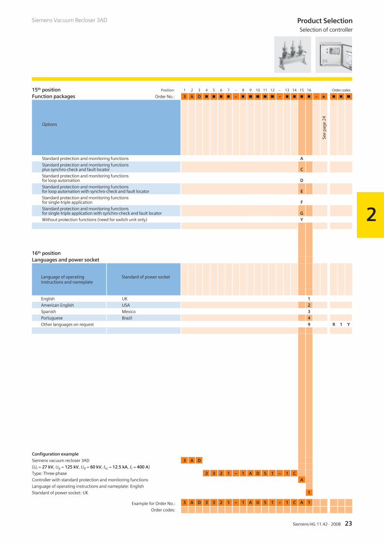
15th position Position: 1 2 3 4 5 6 7 – 8 9 10 11 12 – 13 14 15 16 Order codes
Function packages Order No.: 3 A D � � � � – � � � � � – � � � � – � � � �
Standard protection and monitoring functions AStandard protection and monitoring functionsplus synchro-check and fault locator CStandard protection and monitoring functionsfor loop automation DStandard protection and monitoring functionsfor loop automation with synchro-check and fault locator EStandard protection and monitoring functionsfor single-triple application FStandard protection and monitoring functionsfor single-triple application with synchro-check and fault locator GWithout protection functions (need for switch unit only) Y
16th positionLanguages and power socket
English UK 1American English USA 2Spanish Mexico 3Portuguese Brazil 4Other languages on request 9 R 1 Y
Configuration example
Siemens vacuum recloser 3AD 3 A D
(Ur = 27 kV, Up = 125 kV, Ud = 60 kV, Isc = 12.5 kA, Ir = 400 A)
Type: Three-phase 3 3 2 1 – 1 A D 5 1 – 1 C
Controller with standard protection and monitoring functions A
Language of operating instructions and nameplate: English
Standard of power socket: UK 1
See
page
24
Language of operating Standard of power socketinstructions and nameplate
Example for Order No.: 3 A D 3 3 2 1 – 1 A D 5 1 – 1 C A 1
Order codes:
Options
Product SelectionSelection of controller
Siemens Vacuum Recloser 3AD

2
24 Siemens HG 11.42 · 2008
Selection of additional equipment Position: 1 2 3 4 5 6 7 – 8 9 10 11 12 – 13 14 15 16 Order codes
Order No.: 3 A D � � � � – � � � � � – � � � � – � � � �
Ambient temperature down to –40 °C – Z A 3 8Seaworthy packing inside Germany – Z F 0 2Stainless steel for tank, control cubicle – Z T 0 1Radio modem power supply 12 V DC – Z T 0 2Serial to Ethernet converter – Z T 0 3Pole mounting frame with bracket for surge arrester(source and load side) – Z T 2 1Pole mounting frame – Siemens design –(with bracket for surge arresters, source and load side) – Z T 2 2Further non-listed special versions (only after consultation withyour responsible sales partner). Information additionally in clear text – Z Y 9 9
Configuration exampleSiemens vacuum recloser 3AD 3 A DRated voltage Ur = 27 kVRated lightning impulse withstand voltage Up = 125 kVRated short-duration power-frequency withstand voltage Ud = 60 kVRated short-circuit breaking current Isc = 12.5 kARated normal current Ir = 400 AType: Three-phase 3 3 2 1 –Recloser for pole mounting incl. control cubicle and control cable 1
Current and voltage measuring: current transformers, 1 CT integrated per pole A
Controller size: E12, 12 function keys,
16 tri-color LEDs, 33 binary inputs, 30 binary outputs D
Auxiliary voltage 110/120 V AC 5
Length of control and sensor cable 6 m 1 –
Communication protocol IEC 60870-5-103 and Modbus RTU 1
Communication interfaces 1 x USB, 2 x RS485, 1 x IRIG-B C
Controller with standard protection and monitoring functions A
Language of operating instructions and nameplate: English
Standard of power socket: UK 1
Seaworthy packing inside Germany – Z F 0 2
Stainless steel for tank, control cubicle – Z T 0 1
Options
Example for Order No.: 3 A D 3 3 2 1 – 1 A D 5 1 – 1 C A 1 – Z
Order codes: F 0 2 + T 0 1
Product SelectionSelection of additional equipment
Siemens Vacuum Recloser 3AD

2
25Siemens HG 11.42 · 2008
Accessories and spare parts
A wide range of spare parts and accessories is available.Please contact your responsible sales partner and the orderprocessing department in our Switchgear Factory in Berlin.
Product SelectionAccessories and spare parts
Siemens Vacuum Recloser 3AD
Note:For any request regarding spare parts,subsequent deliveries, etc. the followingdetails are necessary:– Type designation– Serial No.– Design code– Year of manufacture
Data on the nameplate
����
���
���
��

26 Siemens HG 11.42 · 2008
Siemens Vacuum Recloser 3AD
R-HG
11-3
13.ti
f

27Siemens HG 11.42 · 2008
3
Switch unit driver - discarge switch for the capacitor
Controller with protective cap
Contents Page
Technical Data
Electrical data, dimensions and weights:
Voltage level 12 kV
Voltage level 15.5 kV
Voltage level 27 kV
Voltage level 38 kV
27
28
28
29
29
Technical DataContents
R-HG
11-3
14.ti
fR-
HG11
-315
.tif
Siemens Vacuum Recloser 3AD

28 Siemens HG 11.42 · 2008
3
Technical DataElectrical data, dimensions and weights
12 kV50/60 Hz
Ir tk Isc Ima Up Ud
A s kA kA kV kV mV mm mm mm kg A A
3AD�122 … 630 � 3 12.5 31.5 75 42 24 810 312 287 142 2 10
3AD�123 … 800 � 3 12.5 31.5 75 42 24 810 312 287 142 2 10
15.5 kV50/60 Hz Ir tk Isc Ima Up Ud
A s kA kA kV kV mV mm mm mm kg A A
3AD�221 … 400 � 3 12.5 31.5 110 50 24 810 312 287 142 2 10
3AD�222 … 630 � 3 12.5 31.5 110 50 24 810 312 287 142 2 10
3AD�223 … 800 � 3 12.5 31.5 110 50 24 810 312 287 142 2 10
3AD�232 … 630 � 3 16 40 110 50 24 810 312 287 142 2 10
3AD�233 … 800 � 3 16 40 110 50 24 810 312 287 142 2 10
Rat
edn
orm
alcu
rren
t
Rate
dop
erat
ing
sequ
ence
:O-0
.2s
-CO
-2s
-CO
-2s
-CO
(-30
s-C
O)
-Loc
k-ou
t
Rate
ddu
ratio
nof
shor
t-ci
rcui
t
Rate
dsh
ort-
circ
uitb
reak
ing
curr
ent
Rate
dsh
ort-
circ
uitm
akin
gcu
rren
t
Rate
dlig
htni
ngim
puls
ew
ithst
and
volta
ge
Rate
dsh
ort-
dura
tion
pow
er-f
requ
ency
with
stan
dvo
ltage
Vol
tage
drop
ΔUbe
twee
nco
nnec
tions
Cre
epag
edi
stan
ce,p
hase
-to-
eart
h
Cle
aran
ce,
phas
e-to
-pha
se
Min
imum
clea
ranc
e,ph
ase-
to-e
arth
Wei
ght
Line
char
ging
curr
ent
Cab
lech
argi
ngcu
rren
t
Siemens Vacuum Recloser 3AD
Order No.

29Siemens HG 11.42 · 2008
3
27 kV50/60 Hz
Ir tk Isc Ima Up Ud
A s kA kA kV kV mV mm mm mm kg A A
3AD�321 … 400 � 3 12.5 31.5 125 60 24 810 312 287 142 5 25
3AD�322 … 630 � 3 12.5 31.5 125 60 24 810 312 287 142 5 25
3AD�323 … 800 � 3 12.5 31.5 125 60 24 810 312 287 142 5 25
3AD���� ... 400 � 3 12.5 31.5 150 60 On request 5 25
3AD����… 630 � 3 12.5 31.5 150 60 On request 5 25
3AD����… 800 � 3 12.5 31.5 150 60 On request 5 25
3AD����… 630 � 3 16 40 150 60 On request 5 25
3AD����… 800 � 3 16 40 150 60 On request 5 25
38 kV50/60 Hz Ir tk Isc Ima Up Ud
A s kA kA kV kV mV mm mm mm kg A A
3AD����… 630 � 3 12.5 31.5 170 70 On request 5 40
3AD����… 800 � 3 12.5 31.5 170 70 On request 5 40
3AD����… 630 � 3 16 40 170 70 On request 5 40
3AD����… 800 � 3 16 40 170 70 On request 5 40
Technical DataElectrical data, dimensions and weights
Siemens Vacuum Recloser 3AD
Rat
edn
orm
alcu
rren
t
Rate
dop
erat
ing
sequ
ence
:O-0
.2s
-CO
-2s
-CO
-2s
-CO
(-30
s-C
O)
-Loc
k-ou
t
Rate
ddu
ratio
nof
shor
t-ci
rcui
t
Rate
dsh
ort-
circ
uitb
reak
ing
curr
ent
Rate
dsh
ort-
circ
uitm
akin
gcu
rren
t
Rate
dlig
htni
ngim
puls
ew
ithst
and
volta
ge
Rate
dsh
ort-
dura
tion
pow
er-f
requ
ency
with
stan
dvo
ltage
Vol
tage
drop
ΔUbe
twee
nco
nnec
tions
Cre
epag
edi
stan
ce,p
hase
-to-
eart
h
Cle
aran
ce,
phas
e-to
-pha
se
Min
imum
clea
ranc
e,ph
ase-
to-e
arth
Wei
ght
Line
char
ging
curr
ent
Cab
lech
argi
ngcu
rren
t
Order No.

30 Siemens HG 11.42 · 2008
3
Maßbild 1
Maßbild 2
Dimension drawings
����
����
��
�
��
���
���
� �
Dimensions of control cubicle
Technical DataDimension drawings
Siemens Vacuum Recloser 3AD
��������
����
���
���
��
���
���
���
��
���
��
Dimensions of switch unit

31Siemens HG 11.42 · 2008
3
Technical DataDimension drawings
Siemens Vacuum Recloser 3AD
Maßbild 2
Dimension drawings
����
���
��
�
���
�����
���
���
� ��
���
���
���
� �
Dimensions of switch unit with pole mounting frame

32 Siemens HG 11.42 · 2008
R-HG
11-1
81.ti
f
Siemens Vacuum Recloser 3AD

33Siemens HG 11.42 · 2008
4
Contents Page
Annex
Inquiry form
Configuration instructions
Configuration aid
33
34
35
AnnexContents
Foldout page
Siemens Vacuum Recloser 3AD
Switchgear Factory in Berlin, Germany
R-HG
11-1
80.e
ps

34 Siemens HG 11.42 · 2008
4
AnnexInquiry form
Inquiry concerning
� Siemens vacuumrecloser 3AD
Please
� Submit an offer� Call us� Visit us
Your address
Company
Dept.
Name
Street
Postal code/city
Phone
Fax
Siemens AG
Dept.
Name
Street
Postal code/city
Fax
Technical dataOther values
Rated voltage � 12 kV
� 27 kV
� 15.5 kV
� 38 kV � _ _ _ kV
Rated lightning impulse
withstand voltage
� 75 kV
� 150 kV
� 110 kV
� 170 kV
� 125 kV
� _ _ _ kV
Rated short-duration
power-frequency
withstand voltage
� 42 kV
� 60 kV
� 50 kV
� 70 kV � _ _ _ kV
Rated short-circuit
breaking current
� 12.5 kA � 16 kA � _ _ _ kA
Rated normal current � 400 A � 630 A � 800 A � _ _ _ A
Secondary equipment
For possible combinations see pages 20 to 23
Recloser configuration � Recloser for
pole mounting
� Without control
cubicle
� Made of
stainless steel
� Others
� Application in
substation
Current and voltage sensing � Integrated current
transformers
� Integrated voltage
sensors
� External voltage
transformers
Controller equipment � 4 binary inputs
� 34 binary inputs
� 9 binary outputs
� _ _ _
� 14 binary inputs
� 17 binary outputs
� 24 binary inputs
� 25 binary outputs
Auxiliary voltage � _ _ _ V DC � _ _ _ V AC, _ _ _ Hz
Control and sensor cable � Without � 6 m � _ _ _ m
Communication interfaces � USB
� Optical
� RS485
� IRIG-B
� RS232
Function packages additional
to standard functions
� Synchronizing and
synchro-check
� Loop automation
� Fault locating
� Single-triple
Please copy, fill in and return to yourSiemens partner
Application and other requirements
� Please check off _ _ _ Please fill in
Siemens Vacuum Recloser 3AD

You prefer to configure your Siemens vacuum recloser 3AD on your own?Please follow the steps for configuration and enter the order number in the configuration aid.Alternatively you can also use your prompted online configurator under www.siemens.com/energy
Instruction for configuration of the Siemens vacuum recloser 3AD
1st step: Definition of the primary part (see pages 17 to 19)
Please specify the following ratings: Possible options:
Rated voltage (Ur) Ur: 12 kV to 38 kV
Rated lightning impulse withstand voltage (Up) Up: 75 kV to 170 kV
Rated short-duration power-frequency withstand voltage (Ud) Ud: 42 kV to 70 kV
Rated short-circuit breaking current (Isc) Isc: 12.5 kA and 16 kA
Rated normal current (Ir) Ir: 400 A to 800 A
These ratings define the positions 4 to 7 of the order number.
2nd step: Definition of the secondary equipment (see pages 20 to 23)
Please specify the following equipment features: Possible options:
Recloser configuration(position 8)
Recloser incl. control cubicle and cables, recloser without control cubicleand cables, recloser for transformer substation, retrofit recloser
Sensors(position 9)
Integrated current transformers, integrated voltage transformers,external voltage transformers
Controller(position 10)
Housing size, number of function keys and three-color LEDs,number of available binary inputs and outputs
Auxiliary voltage(position 11)
Voltages from 48 V DC to 240 V AC
Cable length of control and sensor cable(position 12)
Standard length 6 m, special lengths possible
Communication protocol(position 13)
IEC 60870-5-103 and Modbus RTU, DNP 3.0
Communication interfaces(position 14)
USB, RS485, RS232, IRIG-B, optical, ST plug
Functions of the controller(position 15)
Standard protection and monitoring functions,synchronizing and synchro-check, fault location
Language of operating instructions and nameplate(position 16)
English, American English, Spanish and Portuguese
These equipment features define the positions 8 to 16 of the order number.
3rd step: Do you have any further requirements concerning the equipment? (Please refer to page 24)
Should you still need more options than the possible special equipment like country-specific mains sockets,weather resistance down to –40 °C, stainless-steel design, etc. please contact your responsible sales partner.
1 2 3 4 5 6 7 – 8 9 10 11 12 – 13 14 15 16
� � � � � � � – � � � � � – � � � � – Z
3 A D – –
+ + + +
+ + + +
3 A D – –
+ + + +
+ + + +
3 A D – –
+ + + +
+ + + +
3 A D – –
+ + + +
+ + + +
3 A D – –
+ + + +
+ + + +
3 A D – –
+ + + +
+ + + +
3 A D – –
+ + + +
+ + + +
3 A D – –
+ + + +
+ + + +
3 A D – –
+ + + +
+ + + +
For configuration of yourSiemens vacuum recloser 3AD
35Siemens HG 11.42 · 2008
See
page
20
See
page
20
See
page
21
See
page
21
See
page
22
See
page
22
See
page
22
See
page
23
See
page
23
See
page
24
See
page
17
to See
page
19

For questions concerning PowerTransmission and Distribution:You can contact our Customer SupportCenter 24 hours a day, 365 days a year.Tel.: +49 180/524 70 00Fax: +49 180/524 24 71(Charges depending on provider)E-Mail: [email protected]/energy-support
Siemens AGEnergy SectorMedium Voltage DivisionNonnendammallee 10413623 BerlinGermany
www.siemens.com/energy
Subject to change without noticeOrder No. E50001-K1511-A421-A1-7600Printed in GermanyDispo 31601KG 03.08 1.0 36 En103063 6101/6519
The information in this document contains general descriptions of the technical options available, which do not always have to be present in individual cases.The required features should therefore be specified in each individual case at the time of closing the contract.
R-HG
11-1
82.ti
f
If not stated otherwise on the individual pages of this catalog,we reserve the right to include modifications, especially regardingthe stated values, dimensions and weights.Drawings are not binding. All product designations used aretrademarks or product names of Siemens AG or other suppliers.If not stated otherwise, all dimensions in this catalog are givenin mm.
Responsible for
Technical contents: General editing:Siemens AG, Dept. PTD M C PPM Siemens AG, Dept. PTD CC MBerlin Erlangen