Embed Size (px)
Citation preview

ELECTRICAL MACHINESUNIBOX & MS4
Medium voltage Electric motors
�

�
PRODUCT TOPIC PG
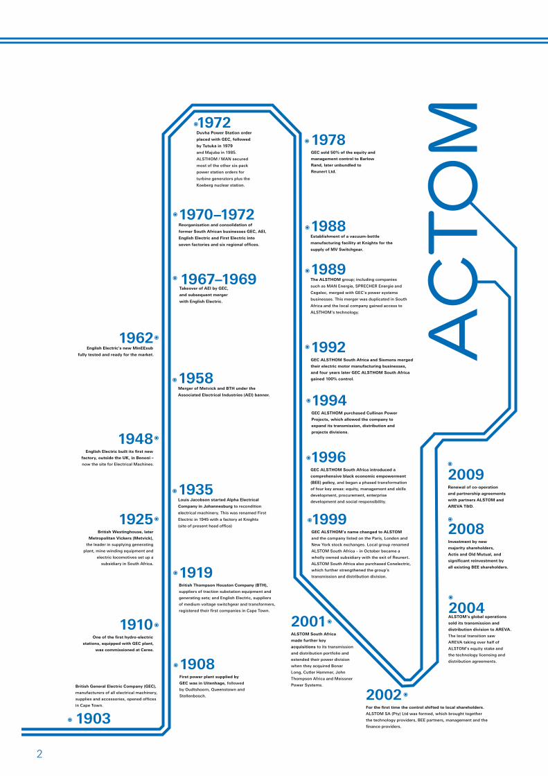
ACTOM our company history �
Who is ACTOM �
UNIBOX – Concept 4
UNIBOX – Frame sizes 4
UNIBOX – Output ratings 4
UNIBOX – Electrical supply -voltages 4
UNIBOX – Standards and specifications 4
UNIBOX – Duty and ratings 4
UNIBOX – Starting 4
UNIBOX – Mounting 5
UNIBOX – Dimension standards 5
UNIBOX – Protection and cooling 5
UNIBOX – Vibration 5
UNIBOX – noise levels 5
UNIBOX – Frame construction 6
UNIBOX – Stator core 6
UNIBOX – Stator windings 6
UNIBOX – Stator core 6
UNIBOX – Rotor construction 6
Index - Medium Voltage Motor Series
Who is ACTOMACTOM (Pty) Ltd currently is the larg-est manufacturer and distributor of electrical equipment in South Africa, employing about 6 000 people and with an annual order intake in excess of R5bn. ACTOM is a BEE compliant black owned company currently with �� operating units, �7 production facilities and �8 distribution centres throughout South Africa. Continual organic evolution is seeing ACTOM grow on an annual basis, providing both impressive economy’s of scale coupled an ever growing pool of tech-nological products and services.
ACTOM Electrical Machines has it’s head office and manufacturing plant
located in Benoni South Africa, from where all aspects of design, develop-ment and manufacturing operations are conducted.
ACTOM partners Alstom France for environmental equipment and in serving the maintenance, upgrade and retrofit market for larger boil-ers, as well as for railway transport activities.
ACTOM holds exclusive distribu-tion, technology and representation rights for Alstom Grid (formerly the Transmission business of Areva T&D) in Southern Africa and maintains management, technical and com-
mercial links to Alstom Grid business units in Europe.
Following the acquisition by Schneider Electric of the global Distribution business of Areva T&D, the distribu-tion, technology and representation agreements that existed between ACTOM and Areva will remain in place until such time as a new agree-ment has been concluded.
ACTOM formerly traded under the name Alstom South Africa and re-branded to ACTOM in September �009.
UNIBOX – Bearings and lubrication 7
UNIBOX – Ventilation systems 9
UNIBOX – Terminal boxes 10
UNIBOX – Noise reduction 10
UNIBOX – Silencers 10
UNIBOX – Paint system 11
UNIBOX – Dimension tables 11
MS4 – Concept 1�
MS4 – General specification 1�
MS4 – Frames and cooling 1�
MS4 – Fan design 1�
MS4 – Stator design 1�
MS4 – Rotor design 1�
MS4 – Bearing design 1�
MS4 – Terminal arrangement 14
MS4 – Accessories 14
MS4 – Dimension tables 15
ACTOM Contact details 16

4
CONCEPT
This heavy duty rugged UNIBOX large frame motor series is designed in Benoni South Africa for applica-tions typically in the Power Station, Mining and heavy industrial market sectors. The design is suitable for both Cage and Slipring Induction motor formats.
FRAME SIZES
The UNIBOX motor series is available in all standard motor shaft heights ranging from �55mm to 1000mm with international standard foot or flange fixing arrangements. Non standard dimensioned products are available on request.
OUTPUTS
UNIBOX output ratings are designed to suit client specific requirements and applications at ratings up to 15MW.
ELECTRICAL SUPPLY
UNIBOX windings are designed as standard for �,�kV, 6,6kV 11kV and 15kV at 50Hz. Other international voltage supply standards can be ac-commodated on request.
STANDARDS AND SPECIFICATIONS
The UNIBOX motor series is electri-cally and mechanically designed in accordance to the IEC600�4. Every effort is made to accommodate client specific requirements in addition to the standard design logic.
DUTY AND RATING
The most frequent UNIBOX design requirement is for a continuous run-ning duty cycle S1, in accordance with IEC 600�4. Other duties can be accommodated to suit special applications. ACTOM engineers are able to advise clients in respect of the correct matching of the machine against intended duty parameters.
STARTING
Cage rotor induction motors are de-signed to take account of the driven machinery torque and speed charac-teristics, ensuring that adequate ac-celerating torque is available, whilst still limiting the starting currents and resultant heat build up in the stator windings. Wound rotor induc-tion motors are designed to provide enhanced starting characteristics off relatively limited supply systems.
UNIBOX SERIES FABRICATED FRAME MV MOTORS
A large frame 7MW 11kV UNIBOX Slipring Mill motor being crated and prepared for export.
A small frame UNIBOX series motor with sleeve bearings and an inlet silencer.
5
MOUNTING
UNIBOX standard mounting configu-rations are IM1001, IM100�, IM�001 and IM�801 as defined in IEC600�4-7. The frame designs are suitable for either holding down bolts or founda-tion bolts. Vertical jacking points are provided in close proximity to these fixing points to facilitate easier shim-ming on installation for alignment.
DIMENSIONS
UNIBOX shaft extensions, frame and foot fixing dimensions are in accordance with the requirements of IEC6007�-�. Whilst these are standard build configurations ACTOM is able to build custom frames to suit inter-changeability requirements where replacement of existing dated plant is required.
PROTECTION AND COOLING
The UNIBOX enclosure is designed in accordance with IEC600�4-5, to both protect personnel from danger and to protect the machine from harm-
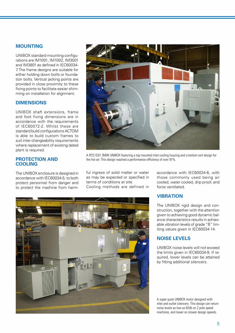
A IP22 IC01 3MW UNIBOX featuring a top mounted inlet cooling housing and a bottom exit design for the hot air. This design reached a performance efficiency of over 97%.
A super quiet UNIBOX motor designed with inlet and outlet silencers. This design can return noise levels as low as 82db on 2 pole speed machines, and lower on slower design speeds.
ful ingress of solid matter or water as may be expected or specified in terms of conditions at site.Cooling methods are defined in
accordance with IEC600�4-6, with those commonly used being air cooled, water cooled, drip proof, and force ventilated.
VIBRATION
The UNIBOX rigid design and con-struction, together with the attention given to achieving good dynamic bal-ance characteristics results in achiev-able vibration levels of grade “B” lim-iting values given in IEC600�4-14.
NOISE LEVELS
UNIBOX noise levels will not exceed the limits given in IEC600�4-9. If re-quired, lower levels can be attained by fitting additional silencers.

6
FRAME CONSTRUCTION
The UNIBOX motor has a robust, box type, heavy gauge mild steel plate fabricated frame. The machine lifting points are integral with the end plates to which the end shields and flange mounted bearings are fitted. Foot fixings are integral within the
frame. This heavy duty frame con-struction reduces flexing, vibration, noise levels and provides the support for the plug-in stator core pack. The welded frame is stress relieved prior to machining.Jacking screws, suitable for vertical
height adjustment are provided on the motor feet.Both end shields are provided with inspection plugs at the appropriate di-ameter, which when removed provide access for air gap measurement.The frame is fitted on final assembly with a comprehensive stainless steel rating plate, that includes all con-nection schematics, bearing details with lubrication as well as key motor specification data.
STATOR CORE
The UNIBOX stator core consists of packets of laminations sepa-rated by radial ventilating ducts. The laminations are manufactured from low loss, non-grain orientated silicon steel. These laminations are manufactured in a ring format for ma-chines up to a 710mm frame and in a segmental format for larger frame machines.
STATOR WINDINGS
The stator coils are formed from annealed copper strip. All the coils are insulated with the appropriate number of layers of mica tape prior to the application of the dielectric and armour finishing tapes. The coils are subjected to elevated impulse volt-age, inter-turn insulation tests before they are fitted into the stator slots and again after all coils have been placed in the fully lined stator slots.The coils are wedged along the full length of the core. When required for higher efficiency designs, the wedges are made from a magneti-cally permeable material. A high volt-age test is carried out after wedging. Each end winding is securely braced to epoxy resin bonded glass fibre rings made from braided glass fibre sleeving, to which the outer end of each coil is lashed with woven glass and or polyester tape. This ensures that the coil ends form a rigid self supporting structure, which is capa-ble of withstanding the mechanical forces produced by full voltage direct on line starting, or from reconnect-ing to an alternative supply. All coil insulation, slot liners, separators and
The UNIBOX motor’s heavy duty ridged frame is designed in South Africa to meet the rigors of the heavy mining and industrial market segments.
7Mw UNIBOX stator core ready for vacuum impregnation.
FRAME CONSTRUCTION

7
wedges etc meet class F insulation requirements.Once the winding connections are completed, the entire winding is vacuum pressure impregnated (VPI) using a solventless epoxy resin. This globally impregnated Resivac sys-tem produces void free insulation. The fully impregnated wound core is the cured in a rotary process to ensure retention of resin in the slots and overhangs. All of these proc-esses are PLC controlled to ensure consistency of product integrity.The completed VPI wound core is heat shrunk into the UNIBOX frame, it is further secured by retaining “horse shoe” pieces fitted over the core bars and then welded into the frame.
ROTOR CONSTRUCTION
Cylindrical UNIBOX rotors are con-structed as either cage or wound rotor design variants.
ROTOR CORES
The UNIBOX rotor core is built up from either segmental laminations which are dovetailed and keyed di-rectly onto the spider, or from ring type laminations depending on the rotor diameter.The rotor core consists of packets of laminations that are separated by radial cooling ducts, similar to and aligned with those formed in the stator core pack construction.Ring type lamination cores are built up between end plates on a keyed mandrel compressed and clamped prior to heat shrinking onto the shaft or spider, ensuring an interference fit, thus eliminating radial move-ment of the core when in operation
and limiting vibration forces. The shaft is provided with a full length key for positive location of the core assembly.The core assembly is located axi-ally at both ends by means of heavy section keys fitted and welded into grooves on the shaft ribs. This facili-tates core removal from either end.
WOUND ROTORS
The winding is of the bar-wave type, using copper strip, appropriately insulated and firmly wedged into semi-closed slots. The end wind-ings are secured with several layers of resin impregnated glass banding onto support collars to prevent any movement due to rotational forces. The rotor winding leads are threaded
into equally spaced radial holes, di-rectly under the rotor overhang and along a suitably sized, centrally bored hole to the end of the shaft.The fibreglass overhang banding is first cured and then the entire wound rotor is impregnated using the VPI process. All insulation and banding are at least Class F material with the temperature rise at rated output lim-ited to within Class B. Rotor leads are connected to studs attached to the phosphor bronze or stainless steel sliprings, keyed to the shaft.The complete slipring assembly is external of the end shield mounted bearing at the non dive end, and separately enclosed to prevent car-bon dust from being drawn into the motor. Enclosure protection of the slipring housing can be made the
Construction of a standard wound rotor assembly.
ROTOR CONSTRUCTION
Drawing showing the construction of a standard cage design rotor assembly.
8
same as that of the main machine, or to a lower degree of protection as required. The slipring housing covers have windows for easy visual inspection, in addition to large hinged doors and easily removable covers that provide free access to the brush gear for more detailed inspection and maintenance purposes.The brushes are fitted with constant pressure brush holders for opti-mum contact between brushes and sliprings that are both continuously rated. The sliprings can be spiral grooved for improved surface cool-ing and improved brush life where peripheral speed exceeds �0 m/s.Additional features that may be in-cluded on wound rotors are tacho generator or encoder fitments for var-iable speed control and either manual or automatic brush lifting equipment and continuously rated sliprings for those applications where extended slipring / brush life is required.
CAGE ROTORS
The squirrel cage construction is normally constructed from high conductivity copper rotor bars and end rings. The specific matching of torque requirements to the load is achieved by the use of various rotor bar sections, and where necessary for increased torque, either a double cage or high-resistance copper alloy variation is used.Accurately sized rotor bars are drifted through the rotor slots ensuring a tight fit and are brazed to the end rings to form the cage. On all two pole motors and for the larger rotors subject to higher centrifugal forces the end rings are forged and end butt brazed to the bars, which are scarved at each end to a point within the slot to allow for thermal flexing during brazing. The brazing quality is checked and the entire assembly is dynamically balanced after the rotor diameter has been machined and sized in relation to the final air gap dimension, with balance weights added to the shaft arm ends or to the balance rings as appropriate.
BEARINGS AND LUBRICATION
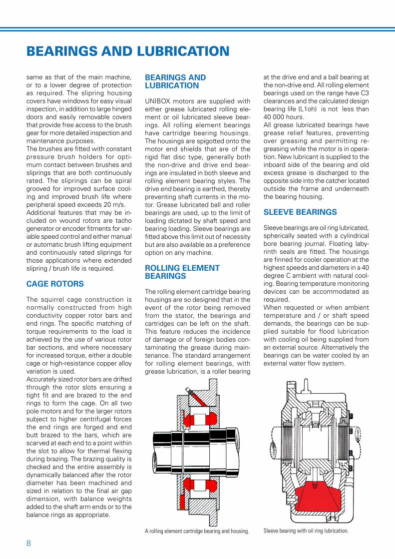
UNIBOX motors are supplied with either grease lubricated rolling ele-ment or oil lubricated sleeve bear-ings. All rolling element bearings have cartridge bearing housings. The housings are spigotted onto the motor end shields that are of the rigid flat disc type, generally both the non-drive and drive end bear-ings are insulated in both sleeve and rolling element bearing styles. The drive end bearing is earthed, thereby preventing shaft currents in the mo-tor. Grease lubricated ball and roller bearings are used, up to the limit of loading dictated by shaft speed and bearing loading. Sleeve bearings are fitted above this limit out of necessity but are also available as a preference option on any machine.
ROLLING ELEMENT BEARINGS
The rolling element cartridge bearing housings are so designed that in the event of the rotor being removed from the stator, the bearings and cartridges can be left on the shaft. This feature reduces the incidence of damage or of foreign bodies con-taminating the grease during main-tenance. The standard arrangement for rolling element bearings, with grease lubrication, is a roller bearing
at the drive end and a ball bearing at the non-drive end. All rolling element bearings used on the range have C� clearances and the calculated design bearing life (L1oh) is not less than 40 000 hours.All grease lubricated bearings have grease relief features, preventing over greasing and permitting re-greasing while the motor is in opera-tion. New lubricant is supplied to the inboard side of the bearing and old excess grease is discharged to the opposite side into the catcher located outside the frame and underneath the bearing housing.
SLEEVE BEARINGS
Sleeve bearings are oil ring lubricated, spherically seated with a cylindrical bore bearing journal. Floating laby-rinth seals are fitted. The housings are finned for cooler operation at the highest speeds and diameters in a 40 degree C ambient with natural cool-ing. Bearing temperature monitoring devices can be accommodated as required.When requested or when ambient temperature and / or shaft speed demands, the bearings can be sup-plied suitable for flood lubrication with cooling oil being supplied from an external source. Alternatively the bearings can be water cooled by an external water flow system.
BEARINGS AND LUBRICATION
A rolling element cartridge bearing and housing. Sleeve bearing with oil ring lubrication.

9
VENTILATION SYSTEMS
The UNIBOX ventilation system is described as “single or double ended radial” depending on the size of the machine. Although total movement of air is axial from one end of the motor to the other in the case of a single ended fan, the main cooling of the core is by radial ducts. The temperature distribution across the machine is uniform resulting in reduced temperature gradients and thus longer insulation life. Designs are proven by a complex equivalent thermal network program used to predict temperatures in different parts of the core.With single ended internal fan ma-chines, the cooling air whether external or from the heat exchanger, is drawn down from the non-drive end of the top cover where it divides into two main paths. One path takes cooling air over the end winding and along both the air gap and the shaft spider, and then through the radial ducts in the rotor and stator cores. The other main path bypasses the core ducts and takes air axially along the outer diameter of the stator core. Here the air progressively mixes with and cools the air from the radial ducts before passing over and cooling the drive end which directs it into the top cover.For double ended internal fan ma-chines, the top cover, stator and rotor are split into two symmetrical air cir-cuits. Cooling air is drawn down from the top cover into the fans at each end of the machine. The air is then forced into the machine core where it divides into two main paths, one taking cooling air over the end wind-ing, along the air gap and through the stator radial ducts back to the top mounted cooler. The second path takes cooling air axially into the shaft spider and then through the shafts radial ducts into the air gap where is mixes with the air on the other path, via the stator radial ducts and back to the top mounted cooler.The top cover of the UNIBOX ma-chine is either open to atmosphere, as in the case with a C-Type machine (IC01) or alternatively consists of an
Internal cooling airflow in a water cooled (CACW) design double ended internal fan system.
Internal cooling airflow in an air to air cooled (CACA) design double ended internal fan system.
integral air to air (CACA) or water cooled ( CACW) heat exchanger in the case of D-Type machines.
SCREEN PROTECTED / DRIP PROOF Heat exchangers (IP22, ICO1)
The UNIBOX stator frame in this design format has an open top, cov-ered by an IP appropriate louvered or screen protected top cover as-sembly. This design is also adaptable
to suit other design fittings for exam-ple those applications that require ducted ventilation extraction.
AIR TO AIR Heat exchangers (CACA, IP55, ICO161)
The top mounted UNIBOX heat ex-changer is in the form of an air to air cooler incorporating aluminium cool-ing tubes that are expanded into steel end plates within the cooler housing

10
to form the top cover that encloses and seals the internal air circuit. The external air cooling circuit is provided by a shaft mounted fabricated fan.
AIR TO WATER Heat exchangers (CACW,IP55,ICW37A81)
This heat exchanger radiator is incorporated into the UNIBOX top cover. Stainless steel cooler tubes are expanded into suitable manifolds located within either end of the cooler. Leak detection devices are also incorporated in to these designs as standard.
NEMA II (IPW24/44, IC01)
This enclosure is designed generally to meet the requirements of NEMA II. The enclosure is designed to give protection corresponding to IPW�4 (without filters) or IPW44 (with filters). The stator frame has a top mounted fabricated steel cover, with three 90 degree baffles and screen protected inlet and outlet openings.
FANS
All fans are fabricated from steel and are fitted by means of a key and an interference fit directly onto the mo-tor shaft. Designs are available for bi-directional as well for uni-directional rotation.
FAN COWLS
The fan cowls on D-TYPE UNIBOX machines are manufactured from fabricated steel with internal baf-fles to accurately guide the airflow. Necessary inlet screens are provided as standard.
TERMINAL BOXES AND TERMINATIONS
The standard position of the UNIBOX terminal box is on the right hand of the motor looking from the drive side shaft end, but this can be posi-tioned on the opposite side should client specifics require. Insulated stud type terminal arrangements are
available to suit various requirements pertaining to differing operating en-vironments, system fault capacity, supply voltages, as well as a variety of terminal box mounted auxiliary equipment and cable types. Whilst the neural point is usually internal, it is possible to bring out the neutral star point to either a separate termi-nation box, or alternatively include it within the main termination box.An earth terminal is provided as standard on the motor frames adja-cent to the main terminal box.UNIBOX terminal boxes are fitted with suitable gland plates as required by specification, or with trifurcating boxes equipped with cables glands, in either straight or angled variants to facilitate easier cabling.The option exists for either Fabel or Makulu design phase insulated ter-mination boxes. These are fabricated boxes incorporating a pressure relief
diaphragm and desiccators for sup-plies up to 15kV. These box designs are fault tested for through fault cur-rents up to 45kA for 0,�5 seconds.Box designs are weather protected and are suitable for Zone � areas.All auxiliary boxes, as required by specification are fabricated from steel.
NOISE REDUCTION
The UNIBOX motor has been de-signed with low overall noise levels and particular attention has been paid to the three basic sources of noise: Bearing, electromagnetic and fan noise.Bearing housing and lubrication system designs are such that allow for easy maintenance reducing the chances of noise being produced as a result of inadequate lubrication.Noise from the magnetic circuit is minimised by electrical designs using comprehensive computer programmes to analyse noise gen-erating harmonics. Rigid cores and frames in conjunction with the use of vacuum impregnation minimise the risk of core and tooth vibration by raising their resonant frequen-cies well above those of the exciting forces. The UNIBOX internal and external high pressure low aspect ratio cen-trifugal fans are optimized to provide the most efficient ratio of cooling air volumes to mechanical noise levels. The number of fan blades is selected to minimize the risk of harmonic interference between the magnetic noise and the fan blade passing frequency.
SILENCERS
When required to meet the needs of stringent noise specifications the D Type UNIBOX motor can be equipped with a purpose designed cowl exten-sion silencer. This design can also be effectively used to silence the air outlet circuit when necessary. C type UNIBOX motors silencers are contained within the inlet and / or outlet of the standard top cover.
A steel fabricated termination box with a Trifurcating extension box (Fabel).
A large volume format standard fabricated termination box (Makulu).

11
PAINT SYSTEM
The paint system chosen for the standard UNIBOX is the result of extensive testing and evaluation of many specially developed systems. The standard system offering is as follows:1 Polyurethane & Epoxy external
coatingAfter cleaning and shot blasting a self etching red oxide primer is applied to a minimum dry film thickness of 10 microns. The intermediate coat, an epoxy primer, is then applied with a minimum dry film thickness of 40 microns. Finally a finishing coat of polyurethane enamel is applied with
a minimum dry film thickness of 65 microns. The total dry film thickness resulting from these three layers will be a minimum of 115 microns.2 Standard internal coatingAfter cleaning and shot blasting a self etching red oxide primer as well as a finishing coat of red oxide insulating paint is applied.
UNIBOX FABRICATED SERIES MOTORS DIMENSION DATA*FRAME POLE A AB AD AF B C C D E ED F G GD H HC HC LE L max* L max*
Ball/R Sleeve ICO1 ICO161 Sleeve SleeveICO 1 ICO 161
355/100 2 610 710 848 570 1000 254 450 80 170 140 22 71 14 335 1328 1508 196 2017 2404355/100 4 up 610 710 848 570 1000 254 450 100 210 160 28 90 16 335 1328 1508 196 2057 2444355/112 2 610 710 848 570 1120 254 450 80 170 140 22 71 14 335 1328 1508 201 2142 2529355/112 4 up 610 710 848 570 1120 254 450 100 210 160 28 90 16 335 1328 1508 201 2182 2569400/112 2 686 847 906 650 1120 280 475 80 170 140 22 71 14 400 1463 1698 213 2237 2601400/112 4 up 686 847 906 650 1120 280 475 125 210 160 32 114 18 400 1463 1698 213 2277 2641400/125 2 686 847 906 650 1250 280 475 80 170 140 22 71 14 400 1463 1698 233 2387 2751400/125 4 up 686 847 906 650 1250 280 475 125 210 160 32 114 18 400 1463 1698 233 2427 2791450/125 2 750 920 933 685 1250 N/A 500 85 170 140 22 76 14 450 1578 1925 173 2355 2812450/125 4 up 750 920 933 685 1250 315 500 140 210 200 36 128 20 450 1578 1925 173 2435 2832450/140 2 750 920 933 685 1400 N/A 500 85 170 140 22 76 14 450 1578 1925 193 2525 2982450/140 4 up 750 920 933 685 1400 315 500 140 210 200 36 128 20 450 1578 1925 193 2605 3062500/125 4 up 850 950 1023 777 1250 335 530 140 250 200 36 128 20 500 1650 2232 213 2525 2937500/160 4 up 850 950 1023 777 1600 335 530 140 250 200 36 128 20 500 1650 2232 213 2875 3287560/140 4 up 950 1100 1087 841 1400 335 560 160 300 225 40 147 22 560 1750 2430 191 2744 3149560/180 4 up 950 1100 1087 841 1800 335 560 160 300 225 40 147 22 560 1750 2430 191 3144 3549630/160 4 up 1060 1210 1161 921 1600 375 600 180 300 225 45 165 25 630 1930 2675 231 3071 3506630/200 4 up 1060 1210 1161 921 2000 375 600 180 300 225 45 165 25 630 1930 2675 231 2471 3306710/180 4 up 1180 1330 1247 1001 1800 N/A 630 200 350 250 45 185 25 710 2058 # 195 3330 #710/224 4 up 1180 1330 1247 1001 2240 N/A 630 200 350 250 45 185 25 710 2058 # 195 3770 #800/200 4 up 1320 1470 1332 1086 2000 N/A 670 225 350 300 50 208 28 800 2315 # 235 3675 #800/250 4 up 1320 1470 1332 1086 2500 N/A 670 225 350 300 50 280 28 800 2315 # 235 4175 #900/224 4 up 1500 1700 1455 1209 2240 N/A 710 250 450 400 56 230 32 900 2497 # 207 4035 #900/280 4 up 1500 1700 1455 1209 2800 N/A 710 250 450 400 56 230 32 900 2497 # 207 4475 #1000/250 4 up 1700 1900 1583 1337 2500 N/A 750 280 500 500 63 257 32 1000 2728 # 247 4475 #1000/315 4 up 1700 1900 1583 1337 3150 N/A 750 280 500 500 63 257 32 1000 2728 # 247 5125 #Note : Dimensions are typical for std applications, ACTOM is able to manufacture both larger & non standard frame's to suit applications at site
* Overall Length where ball or roller bearings are specified will shorten as a function of the removal of two sleeve bearing housings# Due to the variety of cooler designs possible, overall lengths can only be confirmed against specification requirements at enquiry
B/2 B/2

1�
CONCEPT
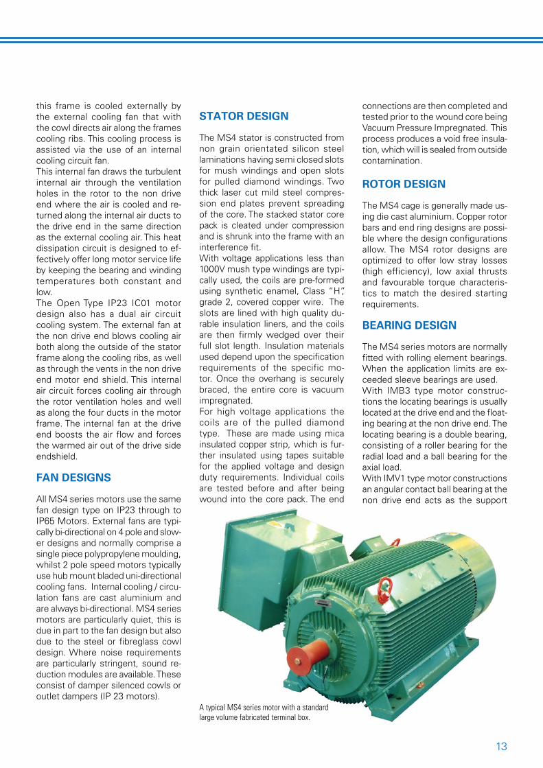
The MS4 compact series cast iron frame medium voltage motors have been developed to suit local require-ments. This compact MV motor series is derived from the previ-ous medium voltage motor series manufactured in Benoni. Due to advancements in insulation systems, laminations and other key materi-als coupled with greatly improved computer controlled manufacturing processes ensures the MS4 motor will remain a robust, reliable and highly efficient motor choice for many years to come. This robust MV motor series is well suited to the arduous service require-ments encountered in our mining and heavy industrial environments. The MS4 design concept centres around an economical life time own-ership profile whilst providing high performance, high efficiency and low maintenance requirements.
GENERAL SPECIFICATION
Standards: In accordance with IEC 600�4.Voltage Range: 400 up to 11000VkW ratings: to 1�00kW depending on the voltage and application dutyEnclosure: TEFC, IP�� IC01 to IP65, IC411 Ribbed cast iron frame.Frame sizes: �55, 400 and 450mm cast Iron ( 500mm Fabricated).Mountings: IMB� - Horizontal & IMV1 - VerticalInsulation: Class “F” VPI RESIVAC ProcessedRating performance: Suitable as standard at 1650 masl at 40°C ambi-ent with Class “B” rise.Bearing designs: Ball, Roller and sleeve options to suit applicationRotor Design: Die cast aluminium cage standard with copper cage op-tion available where suitableTermination boxes: Fabricated boxes with multi mount optionsCooling: External & internal fans, steel or fibreglass cowlsNoise: Low noise levels are stand-ard, additional silencer systems are availableCorrosion protection: Epoxy paint
MS4 SERIES CAST IRON FRAME MV MOTORS
for long term corrosion protection of all parts
FRAME CONSTRUCTION & COOLING
The motor rigid frame and end shields are made from cast iron in respect of frames �55mm to
450mm. Frames sized at 500mm are generally fabricated from mild steel but they retain die cast end shields. All castings are ribbed internally and externally to maximize their cooling surface areas. Totally enclosed IP55 or higher IC411 designs lose the majority of their heat via the frame and end shields,
A typical MS4 series motor with separate phase and star point terminal boxes.
ACTOM MS4 series motor with a standard large volume fabricated terminal box.
1�
this frame is cooled externally by the external cooling fan that with the cowl directs air along the frames cooling ribs. This cooling process is assisted via the use of an internal cooling circuit fan. This internal fan draws the turbulent internal air through the ventilation holes in the rotor to the non drive end where the air is cooled and re-turned along the internal air ducts to the drive end in the same direction as the external cooling air. This heat dissipation circuit is designed to ef-fectively offer long motor service life by keeping the bearing and winding temperatures both constant and low.The Open Type IP�� IC01 motor design also has a dual air circuit cooling system. The external fan at the non drive end blows cooling air both along the outside of the stator frame along the cooling ribs, as well as through the vents in the non drive end motor end shield. This internal air circuit forces cooling air through the rotor ventilation holes and well as along the four ducts in the motor frame. The internal fan at the drive end boosts the air flow and forces the warmed air out of the drive side endshield.
FAN DESIGNS
All MS4 series motors use the same fan design type on IP�� through to IP65 Motors. External fans are typi-cally bi-directional on 4 pole and slow-er designs and normally comprise a single piece polypropylene moulding, whilst � pole speed motors typically use hub mount bladed uni-directional cooling fans. Internal cooling / circu-lation fans are cast aluminium and are always bi-directional. MS4 series motors are particularly quiet, this is due in part to the fan design but also due to the steel or fibreglass cowl design. Where noise requirements are particularly stringent, sound re-duction modules are available. These consist of damper silenced cowls or outlet dampers (IP �� motors).
STATOR DESIGN
The MS4 stator is constructed from non grain orientated silicon steel laminations having semi closed slots for mush windings and open slots for pulled diamond windings. Two thick laser cut mild steel compres-sion end plates prevent spreading of the core. The stacked stator core pack is cleated under compression and is shrunk into the frame with an interference fit.With voltage applications less than 1000V mush type windings are typi-cally used, the coils are pre-formed using synthetic enamel, Class “H”, grade �, covered copper wire. The slots are lined with high quality du-rable insulation liners, and the coils are then firmly wedged over their full slot length. Insulation materials used depend upon the specification requirements of the specific mo-tor. Once the overhang is securely braced, the entire core is vacuum impregnated.For high voltage applications the coils are of the pulled diamond type. These are made using mica insulated copper strip, which is fur-ther insulated using tapes suitable for the applied voltage and design duty requirements. Individual coils are tested before and after being wound into the core pack. The end
connections are then completed and tested prior to the wound core being Vacuum Pressure Impregnated. This process produces a void free insula-tion, which will is sealed from outside contamination.
ROTOR DESIGN
The MS4 cage is generally made us-ing die cast aluminium. Copper rotor bars and end ring designs are possi-ble where the design configurations allow. The MS4 rotor designs are optimized to offer low stray losses (high efficiency), low axial thrusts and favourable torque characteris-tics to match the desired starting requirements.
BEARING DESIGN
The MS4 series motors are normally fitted with rolling element bearings. When the application limits are ex-ceeded sleeve bearings are used. With IMB� type motor construc-tions the locating bearings is usually located at the drive end and the float-ing bearing at the non drive end. The locating bearing is a double bearing, consisting of a roller bearing for the radial load and a ball bearing for the axial load.With IMV1 type motor constructions an angular contact ball bearing at the non drive end acts as the support
A typical MS4 series motor with a standard large volume fabricated terminal box.
14
bearing, and a zero end float spring loaded bearing to guide the rotor at the drive end. The bearings are fitted directly into the end shield or in a separate bearing housing, according to the size of the motor.All rolling element bearings are sealed with felt seals and a V ring which runs with the shaft. This pro-vides protection against the ingress of dust and water jets (IP55), result-ing in both longer bearing life and longer greasing intervals.The bearings are lubricated with lithium soap grease by way of a re-lubricating facility with a self seal-ing lubricating nipple. A generously designed grease chamber for spent grease is provided in the outer bear-ing cover.Sleeve bearings are fitted where the design conditions require it, or by specific client request. The bearings are of the flanged type and are suit-able without modification for both directions of rotation. According to the design bearing load they will have either oil ring lubrication with natural cooling by radiation and convection or they will be provided suitable for a forced oil lubrication system. These bearings are constructed as floating bearings. The rotor must be located axially by way of a limited end float coupling on the driven machine.
TERMINAL ARRANGEMENTS
External connection leads can be connected to the motor either by cable lugs or connection stems via a variety of generously proportioned multi positional fabricated terminal box options with proven designs. The terminal boxes incorporate pressure relief vents that assist in dissipating resultant fault pressure rises in a safe manner.
ACCESSORIES
The following standard accessories can be included when required:• Single phase anti-condensation heaters, wired to external separate auxiliary terminal boxes.• Embedded temperature detectors
(RTD), thermocouples or thermistors can be equipped into each phase of the stator winding, again the leads are wired to external separate auxil-iary terminal boxes.• Calibrated bearing RTDs in a stain-
less steel sheath again the leads are wired to external separate auxiliary terminal boxes.• Surge suppressors or provision for them.
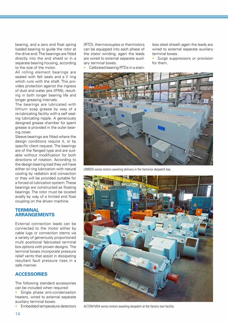
ACTOM MS4 series motors awaiting despatch at the factory test facility.
UNIBOX series motors awaiting delivery in the factories despatch bay.

15
DIMENSIONS OF FRAMES
DIMENSIONS OF STANDARD MS4 FRAME MOTORS *
* Non standard dimension applications can be accommodated by the inclusion of adaptor bases
Frame Poles A AB AD B BB C D E F G H HA HD HC K L BA AC AD355 2 610 730 490 900 1070 200 65 140 18 69 355 44 945 702 28 1815 180 347 869
4 610 730 490 900 1070 200 85 170 22 90 355 44 945 702 28 1845 180 347 8696 610 730 490 900 1070 200 90 170 25 95 355 44 945 702 28 1845 180 347 8698
400 2 686 836 536 1000 1200 224 75 140 20 79,5 400 55 1018 787 35 1945 220 387 8974 686 836 536 1000 1200 224 95 170 25 100 400 55 1018 787 35 1975 220 387 8976 686 836 536 1000 1200 224 100 210 28 106 400 55 1018 787 35 1975 220 387 8978 686 836 536 1000 1200 224 100 210 28 106 400 55 1018 787 35 2015 220 387 897
450 2 750 900 600 1120 1320 254 85 170 22 90 450 34 1104 883 35 2125 N/A 433 9324 750 900 600 1120 1320 254 110 210 28 116 450 34 1104 883 35 2165 N/A 433 9326 750 900 600 1120 1320 254 120 210 32 127 450 34 1104 883 35 2165 N/A 433 9328 750 900 600 1120 1320 254 120 210 32 127 450 34 1104 883 35 2165 N/A 433 93210 750 900 600 1120 1320 254 120 210 32 127 450 34 1104 883 35 2165 N/A 433 93212 750 900 600 1120 1320 254 120 210 32 127 450 34 1104 883 35 2165 N/A 433 932
500 2 850 1030 670 1250 1490 280 120 210 32 127 500 34 1189 979 42 2345 N/A 479 9684 850 1030 670 1250 1490 280 130 250 32 137 500 34 1189 979 42 2385 N/A 479 9686 850 1030 670 1250 1490 280 130 250 32 137 500 34 1189 979 42 2385 N/A 479 9688 850 1030 670 1250 1490 280 130 250 32 137 500 34 1189 979 42 2385 N/A 479 96810 850 1030 670 1250 1490 280 130 250 32 137 500 34 1189 979 42 2385 N/A 479 96812 850 1030 670 1250 1490 280 130 250 32 137 500 34 1189 979 42 2385 N/A 479 968
Frame Poles A AB AD B BB C D E F G H HA HD HC K L BA AC AD355 2 610 730 490 900 1070 † 65 140 18 69 355 44 945 702 28 † 180 347 869
4 610 730 490 900 1070 † 85 170 22 90 355 44 945 702 28 † 180 347 8696 610 730 490 900 1070 † 90 170 25 95 355 44 945 702 28 † 180 347 8698
400 2 686 836 536 1000 1200 375 75 140 20 79,5 400 55 1018 787 35 2095 220 387 8974 686 836 536 1000 1200 375 95 170 25 100 400 55 1018 787 35 2245 220 387 8976 686 836 536 1000 1200 † 100 210 28 106 400 55 1018 787 35 † 220 387 8978 686 836 536 1000 1200 † 100 210 28 106 400 55 1018 787 35 † 220 387 897
450 2 750 900 600 1120 1320 400 85 170 22 90 450 34 1104 883 35 2270 N/A 433 9324 750 900 600 1120 1320 425 110 210 28 116 450 34 1104 883 35 2500 N/A 433 9326 750 900 600 1120 1320 425 120 210 32 127 450 34 1104 883 35 2500 N/A 433 9328 750 900 600 1120 1320 425 120 210 32 127 450 34 1104 883 35 2500 N/A 433 93210 750 900 600 1120 1320 425 120 210 32 127 450 34 1104 883 35 2500 N/A 433 93212 750 900 600 1120 1320 425 120 210 32 127 450 34 1104 883 35 2500 N/A 433 932
500 2 850 1030 670 1250 1490 450 120 210 32 127 500 34 1189 979 42 2690 N/A 479 9684 850 1030 670 1250 1490 450 130 250 32 137 500 34 1189 979 42 2690 N/A 479 9686 850 1030 670 1250 1490 500 130 250 32 137 500 34 1189 979 42 2780 N/A 479 9688 850 1030 670 1250 1490 500 130 250 32 137 500 34 1189 979 42 2780 N/A 479 96810 850 1030 670 1250 1490 500 130 250 32 137 500 34 1189 979 42 2780 N/A 479 96812 850 1030 670 1250 1490 500 130 250 32 137 500 34 1189 979 42 2780 N/A 479 968
† Available on request if design parameters allow
DIMENSIONS MS4 Low Friction Bearings
DIMENSIONS MS4 Sleeve Bearings

16ACTOM Electrical Machines, Aberdeen Road, Industrial Sites, Benoni 1501, Private Bag 10�6, Benoni 1500, Te1+�7(0)11 899-1111 fax +�7(0)11 899-1�06
HEAD OFFICE BENONI WORKS
Cnr. Aberdeen & Van Dyk Rd, Benoni Industrial Sites
PO Box 1026 Benoni 1500
Tel: 011 899 1111
Fax: 011 899 1371
BLOEMFONTEIN
20 Lombard Street Hilton Bloemfontein 9300
Tel: 051 448 1417
Fax: 051 448 7104
CAPE TOWN
12-16 Hawkins Avenue Epping Industria No 1, 7460
PO Box 276, Eppindus 7475
Tel: 021 532 2000
Fax: 021 532 2013
RUSTENBURG
Ruby Sands Rd, Memorial Park
PO Box 20610 Protea Park, Rustenburg 0300
Tel: 082 317 4783
Fax: 082 803 0195
DURBAN
70 Edwin Swales VC Drive, Rossburgh 4094
Tel: 031 465 4170
Fax: 031 465 4189
NELSPRUIT
Cnr. Kragbron & Bester Street, Nelspruit 1200
PO Box 785 Nelspruit 1200
Tel: 013 753 2121/3
Fax: 013 753 2130
POLOKWANE
115 Blaawberg Street, Ladine Polokwane
Tel: 015 293 0920
Fax: 015 293 0408
STEELPOORT
Building No 1 Steelpoort Ext 10
PO Box 785 Nelspruit 1200
Tel: 013 230 3238
Fax: 013 230 3253
PORT ELIZABETH
200 Kempston Rd, Sidwell P.E.
PO Box 3503 North End 6056
Tel: 041 451 5641
Fax: 041 451 4385
PRETORIA
437 Skilder Street, Silvertondale
PO Box 1304 Silverton 0127
Tel: 012 804 0551
Fax: 012 804 1596
WELKOM
19 10th Street, Voorspoed 9459
PO Box 515 Welkom 9460
Tel: 057 355 2451
Fax: 057 396 2155