Embed Size (px)
Citation preview

1 ... 20FRM � Edition 10.15 � 270 440 1 ... 20FRM � Edition 10.15 � 270 440
Medium Pressure Regulator
FRM
Medium pressure regulator Type FRM
Direct acting pressure regulator with adjustable setpoint springs and modular mounted safety shutoff valve (SAV) In compliance with EN 334 and EN 14382
• Inlet pressures up to 10 bar (1000 kPa)• High flow rate• Stable, accurate and sensitive regulation of the outlet pressure • Admission pressure compensation diaphragm for a high
regulation accuracy• External impulse• Maintenance-friendly• Flange connection according to DN 25 - DN 50

2 ... 20FRM � Edition 10.15 � 270 440
Table of contents FRM
Application 3
Approval 3
Technical data 4 + 5
Pressure taps 6
Nomenclature 7
Adjustment range 8
Selection of regulator springs 9
Selection of SAV springs 10
Dimensions 11 + 12
Function 13
Sectional drawing FRM/SAV 13 + 14
Device selection / flow volume tables 15 - 18
Design example 19 Contact details 20

3 ... 20FRM � Edition 10.15 � 270 440
Pressure regulation of industrial gas burners and gas heating appliances. Also for installation in the municipal and commercial gas supply.
Suitable for gases of gas families 1, 2, 3 and other neutral gases.
Application ApprovalFRM
Spring-loaded, pressure com-pensating regulator with adjusta-ble setpoint springs for regulation of the regulator outlet pressure. External impulse of the regulator outlet pressure.
← Table of contents
EC type-examination certificate according to the EC pressure installation directive.
FRM 100...CE-0085CP0256

4 ... 20FRM � Edition 10.15 � 270 440
Type
Type of gas
Nominal diametersFlanges
Max. inlet pressure
Outlet pressure range
Minimum differential pressure (ND)
Minimum differential pressure (MD)
Minimum differential pressure (HD)
Accuracy class
Lock-up pressure class
Failure mode (diaphram rupture)
Materials
Ambient temperature
IS (integral strength range)
Family 1+2+3
Connecting flange PN 25 according to EN1092-1DN 25 40 50
10 bar (1000 kPa)
30 mbar up to 1500 mbar (3-150 kPa)
270 mbar (27 kPa)
350 mbar (35 kPa)
500 mbar (50 kPa)
up to AC 5 (see adjustment range, page 3)
up to SG 10 (see adjustment range, page 3)
fail-open
Main body housing: cast iron GGG 50Diaphragm housing: steelDiaphragms: NBR
-20 °C to +60 °C
Technical Data FRM
← Table of contents
Spring-loaded medium pressure regulator in compliance with EN334

5 ... 20FRM � Edition 10.15 � 270 440
Type
Response time
Lower adjustment range Wdu
Upper adjustment range Wdo
Materials
IS
< 2 s
10 mbar up to 2500 mbar (1-250 kPa)
40 mbar up to 4000 mbar (4-400 kPa)
Main body housing: cast iron GGG 50Diaphragm housing: aluminiumDiaphragms: NBR
Technical Data SAV
← Table of contents
Safety shut-off valve in compliance with EN14382, class A

6 ... 20FRM � Edition 10.15 � 270 440
1 Vent line connection of the regulator, G 1/2 ISO 228
2 External impulse line connection of the regulator, Ermeto screw connection GE 12- 1/4 for tubes 12 x 1.5
3 External impulse line connection of the SAV, Ermeto screw connection GE 12- 1/4 for tubes 12 x 1.5
4 Vent line connection of the SAV, G 1/4 ISO 228
Pressure taps
4
3
1
2
← Table of contents

7 ... 20FRM � Edition 10.15 � 270 440
Nomenclature
Example FRM 100025 ND / SAV ND FRM 100 025 ND SAV ND
Type Spring-loaded medium pressure regulator
MOP 100 … 10 000 mbar
Nominal diameter DN 25 025DN 40 040DN 50 050
Pressure range, outlet pressure ND Low pressureMD Medium pressureHD High pressure
Safety device SAV Integrated shut-off valve
Pressure range, trip pressure
ND Low pressure
MD Medium pressureHD High pressure
← Table of contents

8 ... 20FRM � Edition 10.15 � 270 440
Adjustment range
← Table of contents
Type Con-nection
Ver-sion
Accuracy class* [AC]
Lock-up pressure
class* [SG]
Outlet pres-sure range Wd
Under-pressure monitoring SAV
Over pressure monitoring SAV
Wdu AG Wdo AG
FRM 100025 ND DN 25 ND AC 10 SG 20 30-100 mbar
FRM 100025 MD DN 25 MD AC 5/10** SG 20 90-420 mbar
FRM 100025 HD DN 25 HD AC 5 SG 10 400-1500 mbar
FRM 100025 ND / SAV ND DN 25 ND AC 10 SG 20 30-100 mbar 10-115 mbar AG 10 40-240 mbar AG 10
FRM 100025 MD / SAV MD DN 25 MD AC 5/10** SG 20 90-420 mbar 35-400 mbar AG 10 180-800 mbar AG 10
FRM 100025 HD / SAV HD DN 25 HD AC 5 SG 10 400-1500 mbar 150-2500 mbar AG 5 500-4000 mbar AG 5
FRM 100040 ND DN 40 ND AC 10 SG 20 30-100 mbar
FRM 100040 MD DN 40 MD AC 5/10** SG 20 90-420 mbar
FRM 100040 HD DN 40 HD AC 5 SG 10 400-1500 mbar
FRM 100040 ND / SAV ND DN 40 ND AC 10 SG 20 30-100 mbar 10-115 mbar AG 10 40-240 mbar AG 10
FRM 100040 MD / SAV MD DN 40 MD AC 5/10** SG 20 90-420 mbar 35-400 mbar AG 10 180-800 mbar AG 10
FRM 100040 HD / SAV HD DN 40 HD AC 5 SG 10 400-1500 mbar 150-2500 mbar AG 5 500-4000 mbar AG 5
FRM 100050 ND DN 50 ND AC 10 SG 20 30-100 mbar
FRM 100050 MD DN 50 MD AC 5/10** SG 20 90-420 mbar
FRM 100050 HD DN 50 HD AC 5 SG 10 400-1500 mbar
FRM 100050 ND / SAV ND DN 50 ND AC 10 SG 20 30-100 mbar 10-115 mbar AG 10 40-240 mbar AG 10
FRM 100050 MD / SAV MD DN 50 MD AC 5/10** SG 20 90-420 mbar 35-400 mbar AG 10 180-800 mbar AG 10
FRM 100050 HD / SAV HD DN 50 HD AC 5 SG 10 400-1500 mbar 150-2500 mbar AG 5 500-4000 mbar AG 5
*Accuracy class / Lock-up pressure class to EN 334**pd = 90-180 mbar: AC 10 pd= 180-420 mbar: AC 5

9 ... 20FRM � Edition 10.15 � 270 440
The response pressure results from the force of the installed adjusting spring and the weight force of the movable parts. By changing the setpoint spring 1, it is possible to set different outlet pressures.
Selection of regulator springs
Specific set range, outlet pressure Wds
Spring colour Ordernumber
Wire diameter[mm]
Length[mm]
Diameter[mm]
Setpoint range [mbar]ND MD HD
Silver 270341 5.5 220 60 30-40 90-110
Green 270345 6.5 220 62 40-55 110-170
Yellow 270346 7.0 220 63 55-80 170-240
Blue 270347 8.0 220 65 80-100 240-330
Black 270348 9.0 220 68 330-420 400-580
Purple 270349 10.0 220 69 560-850
Orange 270350 11.0 220 71 800-1200
Pink 270352 12.0 220 73 1100-15001
← Table of contents

10 ... 20FRM � Edition 10.15 � 270 440
The response pressure results from the force of the installed adjusting spring. The upper response pres-sure (overpressure) is set on the external spring 1 of the measure-ment device. The lower response pressure (vacuum) can be set on the internal spring 2. By changing the setpoint springs, different response pressures can be set.
Selection of SAV springs
Specific set range, underpressure Wdsu
Spring colour Order number Wire diameter [mm] Length [mm] Diameter [mm] Setpoint range [mbar]ND MD HD
White 270353 1.2 60 10.0 10-32Yellow 270355 1.5 55 12.3 24-40Blue 270356 2.0 55 12.3 30-115 35-110Black 270357 2.3 55 12.3 50-250Purple 270358 2.5 55 12.3 80-400 150-500
Orange 270359 2.8 55 12.3 300-1000
Pink 270360 3.0 55 12.5 800-2500
Specific set range, overpressure Wdso
Spring colour Order number Wire diameter [mm] Length [mm] Diameter [mm] Setpoint range [mbar]ND MD HD
Silver 270361 2.2 60 30.0 40-130
Green 270366 2.5 60 30.0 60-190 180-290
Red 270367 2.7 60 30.0 90-240 230-370
Yellow 270368 3.2 60 30.0 300-500
Blue 270369 3.5 60 30.0 400-800 500-1000
Black 270370 3.7 60 30.0 700-1300
Purple 270371 4.0 60 30.0 1000-1800
Orange 270372 4.5 60 30.0 1300-2500
Pink 270373 4.8 60 30.0 1800-4000
1
2
← Table of contents

11 ... 20FRM � Edition 10.15 � 270 440
Dimensions FRM
A
C
D
E
B
Type Ordernumber
p max. [bar / kPa]
DN Dimensions Weight[kg]A B C D E
FRM 100025 ND 270272 10 / 1000 25 500 184 57 492 820 38FRM 100025 MD 270273 10 / 1000 25 380 184 57 492 820 32FRM 100025 HD 270274 10 / 1000 25 380 184 57 502 830 36FRM 100040 ND 270278 10 / 1000 40 500 223 69 505 830 42FRM 100040 MD 270279 10 / 1000 40 380 223 69 505 830 36FRM 100040 HD 270280 10 / 1000 40 380 223 69 515 840 40FRM 100050 ND 270284 10 / 1000 50 500 254 80 515 840 49FRM 100050 MD 270285 10 / 1000 50 380 254 80 515 840 43FRM 100050 HD 270286 10 / 1000 50 380 254 80 525 850 47
← Table of contents

12 ... 20FRM � Edition 10.15 � 270 440
Dimensions FRM with SAV
Type Ordernumber
p max. [bar / kPa]
DN Dimensions Weight[kg]A B C D E
FRM 100025 ND/SAV ND 270275 10 / 1000 25 500 184 232 492 1070 40FRM 100025 MD/SAV MD 270276 10 / 1000 25 380 184 229 492 1070 34FRM 100025 HD/SAV HD 270277 10 / 1000 25 380 184 236 502 1080 38FRM 100040 ND/SAV ND 270281 10 / 1000 40 500 223 243 505 1080 44FRM 100040 MD/SAV MD 270282 10 / 1000 40 380 223 239 505 1080 38FRM 100040 HD/SAV HD 270283 10 / 1000 40 380 223 247 515 1090 42FRM 100050 HD/SAV ND 270287 10 / 1000 50 500 254 252 515 1090 51FRM 100050 HD/SAV MD 270288 10 / 1000 50 380 254 248 515 1090 45FRM 100050 HD/SAV HD 270289 10 / 1000 50 380 254 256 525 1100 49
A
C
E
B
D
← Table of contents

13 ... 20FRM � Edition 10.15 � 270 440
FunctionSectional drawing FRMPressure regulator in open position
1 Control plate 2 Inlet pressure compensation
diaphragm 3 Lower diaphragm shell 4 Lever system 5 Impulse connection for the outlet pressure 6 Working diaphragm 7 Vent connection 8 Setpoint spring
Any condensate from impulse lines must not flow into the pressure regulator.
Combustible gas and gas/air mixtures must not enter the installation space of the adjusting spring.
In case of an increase of the outlet pressure, the working diaphram 6 is pushed upwards, until the force of the setpoint spring 8 is equal to that of the outlet pressure. The upward movement of the working diaphragm 6 causes the lever system 4 to be pulled upwards. In this way, the control plate 1 is then pushed downwards and the valve gap is reduced. The flow volume decreased in this way reduces the outlet pressure until the set nominal value (outlet pressure) is reached and a balance of forc-es at the working diaphragm 6 is established.
1
2
3
5
8
7
6
4
← Table of contents
Mode of operation according to the forcecomparison principle between the force: • of the adjustable setpoint spring,• of the defined return spring,• coming from the differential pressure on the
working diaphragm and• of the weight of the movable parts.
The setting spring acts independently of the weight of the movable parts. The outlet pres-sure is set depending on the preload of the setting spring.
Informationgas carrying and impulse lines and connectinglines must be resistant to thermal, chemical and mechanical stresses. They must also be dura-ble and resistant to deformation and cracks.

14 ... 20FRM � Edition 10.15 � 270 440
FunctionSectional drawing SAVDevice in the closed position
1 Valve disc2 Closing spring3 Ball catch / trigger mechanism4 Chamber with the pressure to be monitored5 Working diaphragm 6 Push rod7 Setpoint spring for pdo8 Setpoint spring for pdu9 Protective cap
Chamber 4 is connected to the outlet pressure via an impulse line. The pressure being monitored acts on the working diaphragm 5. The force of the setpoint springs 7 and 8 acts as counterforce. In case of an unbalance of forces (overpressure or underpressure), the SAV is actuated and the gas supply is blocked.
1
2
34
56
7
9
8
← Table of contents
15 ... 20FRM � Edition 10.15 � 270 440
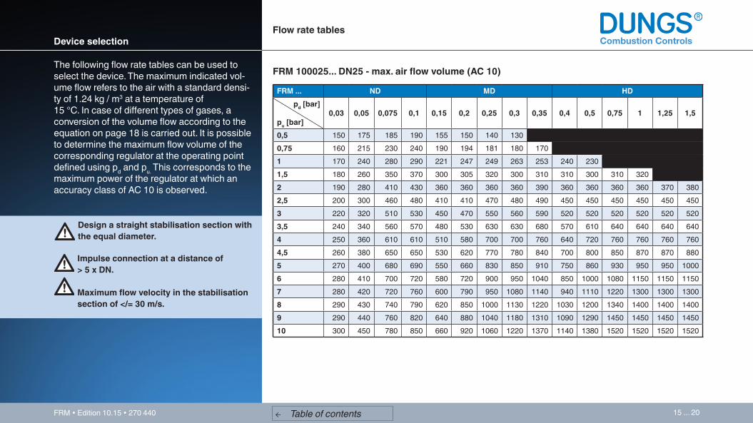
Device selection
The following flow rate tables can be used to select the device. The maximum indicated vol-ume flow refers to the air with a standard densi-ty of 1.24 kg / m3 at a temperature of 15 °C. In case of different types of gases, a conversion of the volume flow according to the equation on page 18 is carried out. It is possible to determine the maximum flow volume of the corresponding regulator at the operating point defined using pd and pu. This corresponds to the maximum power of the regulator at which an accuracy class of AC 10 is observed.
Design a straight stabilisation section with the equal diameter.
Impulse connection at a distance of > 5 x DN.
Maximum flow velocity in the stabilisation section of </= 30 m/s.
Flow rate tables
← Table of contents
FRM ... ND MD HD pd [bar]
pu [bar]0,03 0,05 0,075 0,1 0,15 0,2 0,25 0,3 0,35 0,4 0,5 0,75 1 1,25 1,5
0,5 150 175 185 190 155 150 140 1300,75 160 215 230 240 190 194 181 180 1701 170 240 280 290 221 247 249 263 253 240 2301,5 180 260 350 370 300 305 320 300 310 310 300 310 3202 190 280 410 430 360 360 360 360 390 360 360 360 360 370 3802,5 200 300 460 480 410 410 470 480 490 450 450 450 450 450 4503 220 320 510 530 450 470 550 560 590 520 520 520 520 520 5203,5 240 340 560 570 480 530 630 630 680 570 610 640 640 640 6404 250 360 610 610 510 580 700 700 760 640 720 760 760 760 7604,5 260 380 650 650 530 620 770 780 840 700 800 850 870 870 8805 270 400 680 690 550 660 830 850 910 750 860 930 950 950 10006 280 410 700 720 580 720 900 950 1040 850 1000 1080 1150 1150 11507 280 420 720 760 600 790 950 1080 1140 940 1110 1220 1300 1300 13008 290 430 740 790 620 850 1000 1130 1220 1030 1200 1340 1400 1400 14009 290 440 760 820 640 880 1040 1180 1310 1090 1290 1450 1450 1450 145010 300 450 780 850 660 920 1060 1220 1370 1140 1380 1520 1520 1520 1520
FRM 100025... DN25 - max. air flow volume (AC 10)

16 ... 20FRM � Edition 10.15 � 270 440
Flow rate tablesDevice selection
FRM 100040... DN40 - max. air flow volume (AC 10)
FRM... ND MD HD pd [bar]
pu [bar]0,03 0,05 0,075 0,1 0,15 0,2 0,25 0,3 0,35 0,4 0,5 0,75 1 1,25 1,5
0,5 240 290 290 300 270 270 270 2700,75 260 320 360 450 340 350 350 350 3501 280 350 460 570 400 410 410 440 470 470 4701,5 320 450 550 650 460 530 530 540 590 610 620 630 7402 350 530 630 720 550 620 620 640 700 730 770 820 840 840 8802,5 415 580 700 800 615 700 700 750 800 840 870 1020 1030 1030 11003 460 630 780 890 670 770 770 830 890 940 940 1150 1300 1300 13003,5 505 670 860 970 715 840 840 930 990 1030 1040 1330 1420 1430 15004 540 700 950 1030 755 900 900 1020 1100 1130 1140 1410 1540 1590 17004,5 570 750 1050 1100 790 960 960 1100 1200 1220 1230 1540 1660 1730 19005 610 800 1130 1180 820 1020 1020 1170 1280 1300 1310 1670 1790 1880 20506 700 900 1240 1350 900 1120 1140 1320 1450 1450 1500 1900 1990 2150 23007 790 990 1330 1480 980 1180 1260 1450 1590 1580 1680 2120 2220 2400 25008 870 1070 1410 1550 1040 1220 1350 1570 1750 1690 1820 2300 2420 2600 26509 930 1140 1450 1580 1080 1250 1420 1690 1880 1790 1950 2500 2600 2750 280010 950 1190 1470 1620 1110 1270 1480 1780 2000 1810 2010 2610 2750 2850 2910

17 ... 20FRM � Edition 10.15 � 270 440
FRM 100050... DN50 - max. air flow volume (AC 10)
Flow volume tablesDevice selection
FRM... ND MD HD pd [bar]
pu [bar]0,03 0,05 0,075 0,1 0,15 0,2 0,25 0,3 0,35 0,4 0,5 0,75 1 1,25 1,5
0,5 160 170 230 230 210 210 210 2100,75 200 220 270 270 300 320 320 320 3201 220 260 330 330 390 400 410 410 440 380 3801,5 245 300 390 390 480 530 530 560 670 470 470 530 6152 270 330 460 460 570 630 630 700 870 600 600 700 700 700 7502,5 295 360 540 540 650 730 730 820 1000 740 770 880 900 900 9403 320 400 580 580 720 830 830 920 1100 860 980 1040 1080 1080 11203,5 345 430 620 620 780 890 930 1030 1180 960 1090 1200 1240 1240 13004 365 470 640 640 850 950 1010 1120 1260 1040 1200 1320 1380 1380 15204,5 380 510 690 690 920 980 1080 1200 1300 1120 1290 1440 1500 1500 16405 410 545 740 740 980 1040 1140 1270 1350 1180 1350 1530 1580 1620 17406 470 600 800 800 1060 1130 1240 1380 1450 1290 1460 1570 1660 1780 19607 520 660 860 870 1140 1210 1330 1450 1550 1380 1540 1600 1730 1940 21608 570 710 910 930 1200 1270 1400 1520 1650 1450 1600 1630 1810 2130 23409 620 750 950 980 1250 1320 1470 1560 1750 1500 1640 1660 1870 2240 243010 680 790 990 1050 1300 1380 1510 1590 1850 1530 1680 1680 1900 2340 2510

18 ... 20FRM � Edition 10.15 � 270 440
Type of gas
Natural gas
City gas
NDG
Air
dv
0.65
0.47
1.67
1.00
f
1.24
1.46
0.77
1.00
air density
spec. weight of the gas used
f =
°Vused gas = V air x f ° Spec. Wgt.
[kg/m3]
0.81
0.58
2.08
1.24
Calculation of gas types
← Table of contents

19 ... 20FRM � Edition 10.15 � 270 440
Design exampleDevice selection
Since the effective operating point of the system (550 m3/h natural gas) should correspond as closely as possible to the maximum power of the regulator, for this design example a FRM 100025 DN 25 is used. In this way optimum regulation behaviour can be guaranteed.
FRM 100025... DN25 - max. air flow volume (AC 10) FRM 100040... DN40 - max. air flow volume (AC 10)
VFRM DN 25= 510 m3/h air
Conversion VFRM DN 25 air in VFRM DN 25 natural gas:
VFRM DN 25 natural gas= 510 m3/h * (1.24/0.81)
VFRM DN 25 natural gas= 631 m3/h
VFRM DN 25 natural gas >Vnatural gas system
631 m3/h > 550 m3/h
VFRM DN 40= 755 m3/h air
Conversion VFRM DN 40 air in VFRM DN 40 natural gas:
VFRM DN 40 natural gas= 755 m3/h * (1.24/0.81)
VFRM DN 40 natural gas= 934 m3/h
VFRM DN 40 natural gas >Vnatural gas system
934 m3/h > 550 m3/h
← Table of contents
°
° °
°
°
°°
°
° °
°
°
°°
System dataMedium: natural gasNatural gas specific density: 0.81 kg/m3
Volume flow Vnatural gas system: 550 Nm3/hInlet pressure pu: 4 bar (400 kPa)Outlet pressure pd: 150 mbar (15 kPa)
FRM ... ND MD HD pd [bar]
pu [bar]0,03 0,05 0,075 0,1 0,15 0,2 0,25 0,3 0,35 0,4 0,5 0,75 1 1,25 1,5
0,5 150 175 185 190 155 150 140 1300,75 160 215 230 240 190 194 181 180 1701 170 240 280 290 221 247 249 263 253 240 2301,5 180 260 350 370 300 305 320 300 310 310 300 310 3202 190 280 410 430 360 360 360 360 390 360 360 360 360 370 3802,5 200 300 460 480 410 410 470 480 490 450 450 450 450 450 4503 220 320 510 530 450 470 550 560 590 520 520 520 520 520 5203,5 240 340 560 570 480 530 630 630 680 570 610 640 640 640 6404 250 360 610 610 510 580 700 700 760 640 720 760 760 760 7604,5 260 380 650 650 530 620 770 780 840 700 800 850 870 870 8805 270 400 680 690 550 660 830 850 910 750 860 930 950 950 10006 280 410 700 720 580 720 900 950 1040 850 1000 1080 1150 1150 11507 280 420 720 760 600 790 950 1080 1140 940 1110 1220 1300 1300 13008 290 430 740 790 620 850 1000 1130 1220 1030 1200 1340 1400 1400 14009 290 440 760 820 640 880 1040 1180 1310 1090 1290 1450 1450 1450 145010 300 450 780 850 660 920 1060 1220 1370 1140 1380 1520 1520 1520 1520
FRM... ND MD HD pd [bar]
pu [bar]0,03 0,05 0,075 0,1 0,15 0,2 0,25 0,3 0,35 0,4 0,5 0,75 1 1,25 1,5
0,5 240 290 290 300 270 270 270 2700,75 260 320 360 450 340 350 350 350 3501 280 350 460 570 400 410 410 440 470 470 4701,5 320 450 550 650 460 530 530 540 590 610 620 630 7402 350 530 630 720 550 620 620 640 700 730 770 820 840 840 8802,5 415 580 700 800 615 700 700 750 800 840 870 1020 1030 1030 11003 460 630 780 890 670 770 770 830 890 940 940 1150 1300 1300 13003,5 505 670 860 970 715 840 840 930 990 1030 1040 1330 1420 1430 15004 540 700 950 1030 755 900 900 1020 1100 1130 1140 1410 1540 1590 17004,5 570 750 1050 1100 790 960 960 1100 1200 1220 1230 1540 1660 1730 19005 610 800 1130 1180 820 1020 1020 1170 1280 1300 1310 1670 1790 1880 20506 700 900 1240 1350 900 1120 1140 1320 1450 1450 1500 1900 1990 2150 23007 790 990 1330 1480 980 1180 1260 1450 1590 1580 1680 2120 2220 2400 25008 870 1070 1410 1550 1040 1220 1350 1570 1750 1690 1820 2300 2420 2600 26509 930 1140 1450 1580 1080 1250 1420 1690 1880 1790 1950 2500 2600 2750 280010 950 1190 1470 1620 1110 1270 1480 1780 2000 1810 2010 2610 2750 2850 2910

20 ... 20FRM � Edition 10.15 � 270 440
Subject to technical modification in the interest of technical progress.
← Table of contents
Head of office and factory
Karl Dungs GmbH & Co. KG Siemensstraße 6-10 D-73660 Urbach, GermanyPhone +49 (0)7181-804-0Fax +49 (0)7181-804-166e-mail: [email protected]: www.dungs.com
Subsidiary
Karl Dungs Limited18, Liberty Way Attleborough Fields Ind. Est.GB-Nuneaton CV11 6RZGroßbritannien / Great BritainPhone +44 (0)24/76 37 57 33Fax +44 (0)24/76 34 28 52e-mail: [email protected]: www.dungs.com