Embed Size (px)
Citation preview

March, 2007
MEDIUM-FORMAT DIGITAL CAMERAS:A STUDY INTO THE CALIBRATION, STABILITY ANALYSIS,
AND INTEGRATION WITH HIGH RESOLUTION SATELLITE IMAGERY
Ayman Habib,Gregory Stensaas,and Anna Jarvis

2March, 2007
Overview
• Medium-format digital cameras: introduction.• Camera Calibration• Camera Stability Analysis• Experimental Results• Integration of Aerial and High Resolution Satellite
Imagery
3March, 2007
Traditional Mapping Cameras
Medium Format Digital Cameras
Commercial Digital Cameras

4March, 2007
Analog Camera: WILD RC10

5March, 2007
SONY DSC F717
Medium-Format Digital Cameras

6March, 2007
MFDC Applications
•Aerial surveys of hurricane ravaged regions• Modeling of 3D scenes• Computer Vision• Rapid Mapping
The devastation in Ocean Springs, Miss., taken on Aug. 30, 2005, after Hurricane Katrina slammed the region (NOAA)

7March, 2007
New Issues of Importance•The growth of the field as well as the increase in the diversity of applications has numerous advantages
• However, new issues of concern are to be addressed
• Camera Calibration- Accurate determination of internal camera
characteristics
• Stability Analysis- Confirm that the camera is stable over time

8March, 2007
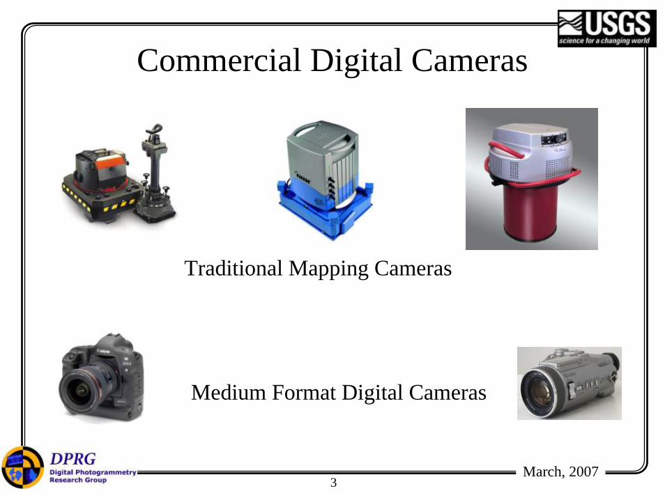
Interior Orientation Parameters (IOP)• Principal point coordinates (xp, yp).• Principal distance (c).• Distortion parameters:
– Radial Lens Distortion (RLD).– De-centering Lens Distortion (DLD).– Affine Deformations (AD).
• The IOP are determined through a bundle adjustment with self-calibration procedure.– Point-based calibration.– Point & line-based calibration.

9March, 2007
Radial Lens Distortion (RLD)

10March, 2007
Decentric Lens Distortion (DLD)
11March, 2007
Affine Deformations (AD)

12March, 2007
Camera Calibration• Calibration parameters describe the internal
characteristics of the implemented camera.

13March, 2007
Interior Orientation
≡
A
a
C
c
B
b
D
d
Lens
Image Space
Object Space
Photography
ac bd
Lens
Image Space
Establishing IO
14March, 2007
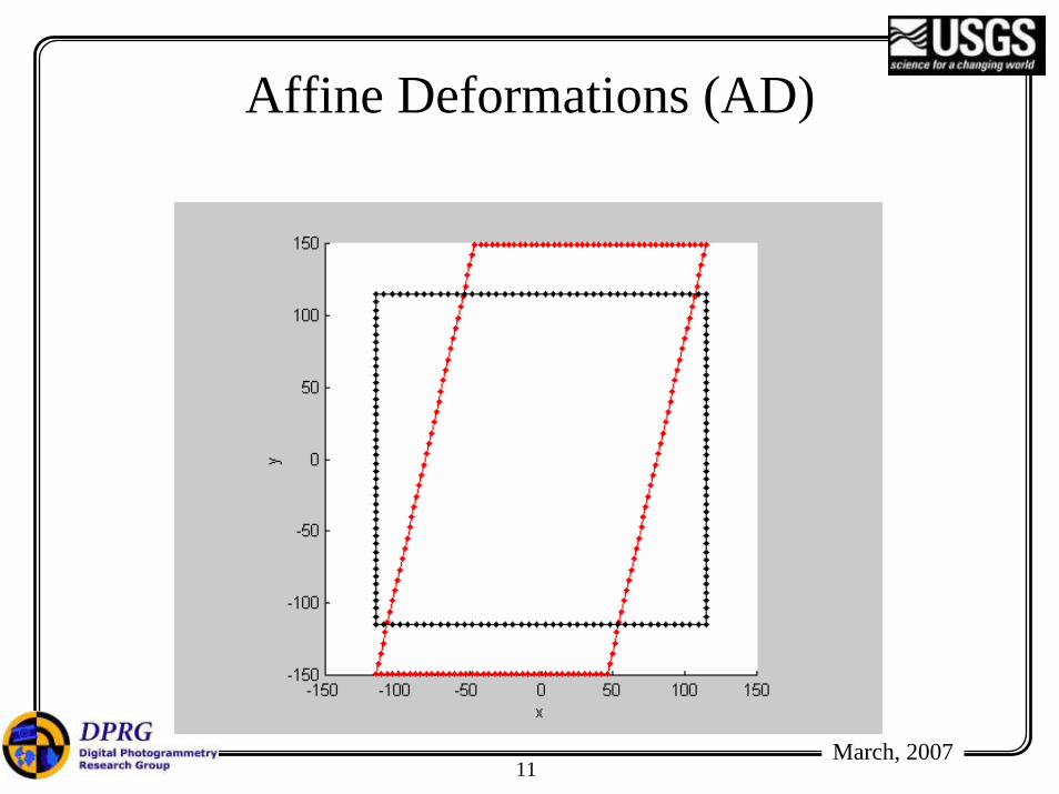
Traditional Versus Proposed Test Field

15March, 2007
Building the Calibration Test Field
16March, 2007
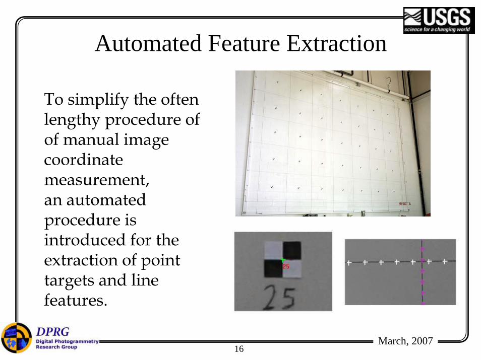
Automated Feature Extraction
To simplify the often lengthy procedure ofof manual image coordinate measurement, an automated procedure is introduced for the extraction of point targets and line features.

17March, 2007
Measurement Environment

18March, 2007
Evaluation Criteria
• Recovery of straightness after calibration and distortion removal.– This is conducted for point and line-based calibration.
• Check point analysis.– RMSE analysis of surveyed targets (30 targets used as
check points).

19March, 2007
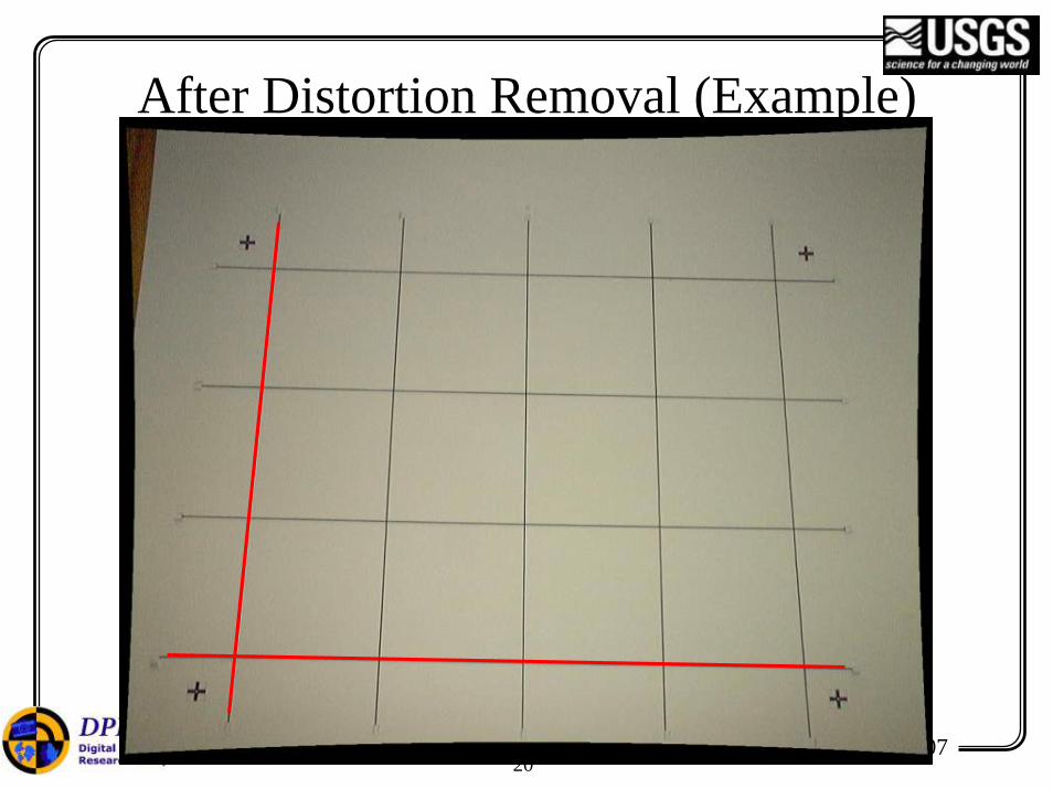
Before Distortion Removal (Example)
• Collinearity does not exist!• Distortions will cause deviations from
straightness in the image space• Modeling and calibration required!
20March, 2007
After Distortion Removal (Example)

21March, 2007
Control Points
Tie Points
Line-Based Calibration (DAC 101)

22March, 2007
Check Point Analysis (DAC 101)
• February 8, 2006 (IOPI):– no of points = 30– RMSE (X) = 0.00035 m– RMSE (Y) = 0.00029 m– RMSE (Z) = 0.00082 m
• February 9, 2006 (IOPII):– no of points = 30– RMSE (X) = 0.00027 m– RMSE (Y) = 0.00046 m– RMSE (Z) = 0.00064 m

23March, 2007
Stability Analysis
ac bd
Lens
Image Space
Reconstructed bundle using IOPI
ac bd
Lens
Image Space
Reconstructed bundle using IOPII
?≡

24March, 2007
• Rotation (ROT)– Same perspective center (no shift allowed)– Rotation allowed
P.C. (0, 0, 0)
pI (xI, yI,-cI)
pII (xII, yII,-cII)
R (ω, ϕ, κ)
SpatialOffset
Original Image Points
Distortion-free Grid Point using IOPI
Distortion-free Grid Point using IOPII
Projected Grid Point of IOPII
Stability Analysis

25March, 2007
• Stability Analysis Results:• σo: 0.0043 mm (Acceptable)
– ω: 95"– φ: 122"– κ: -3"
• Conclusion: The bundles defined by IOPI and IOPII are similar.
• The camera is deemed stable between the two calibration sessions.
Stability Analysis (DAC 101)
Pixel Size = 9 μm
26March, 2007
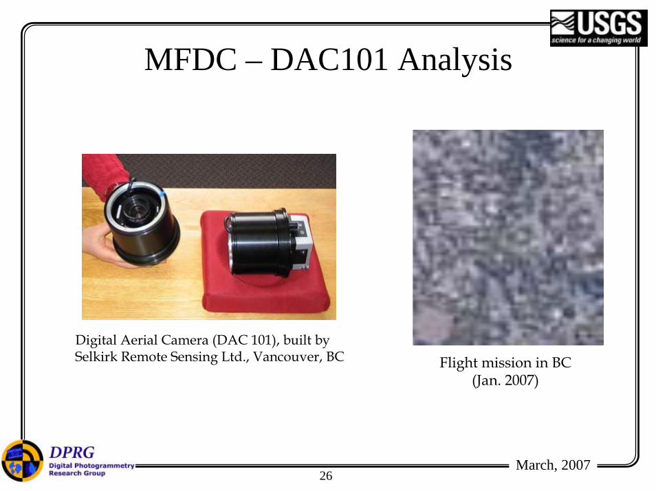
MFDC – DAC101 Analysis
Digital Aerial Camera (DAC 101), built bySelkirk Remote Sensing Ltd., Vancouver, BC Flight mission in BC
(Jan. 2007)

27March, 2007
MFDC – DAC101 Analysis
Feb8_2006 vs. Mar_2007 RMSE = 0.005852
Feb9_2006 vs. Mar_2007 RMSE = 0.006786
Mar2_2006 vs. Mar_2007 RMSE = 0.007632
Apr_2006 vs. Mar_2007 RMSE = 0.009127
DAC101 Stability results
Stereopair 1 Stereopair 2 Stereopair 3 Stereopair 4
Mininumy-parallax
0.06995 0.02568 0.03347 0.01674
Maxiumumy-parallax
2.2636 1.00419 1.51883 1.12511
Mean 0.5603 0.40278 0.57740 0.54501
StandardDeviation
0.6228 0.26875 0.38375 0.42966
Y-Parallax (in pixels) in imagery collected from the DAC101

28March, 2007
MFDC – DAC101 Analysis
DAC101 Stereopairs: observe the lack of y-parallax

29March, 2007
Medium-Format Digital Cameras
• Established a calibration procedure using point and linear features.
• Established meaningful measures for evaluating the stability of given camera from temporal calibration results.
• Developed specifications for regulating the use of medium-format digital cameras.– Incorporated feedback from the mapping industry.

March, 2007
Multi-Sensor Photogrammetric Triangulation:Integration of Aerial and High Resolution Satellite Imagery
31March, 2007
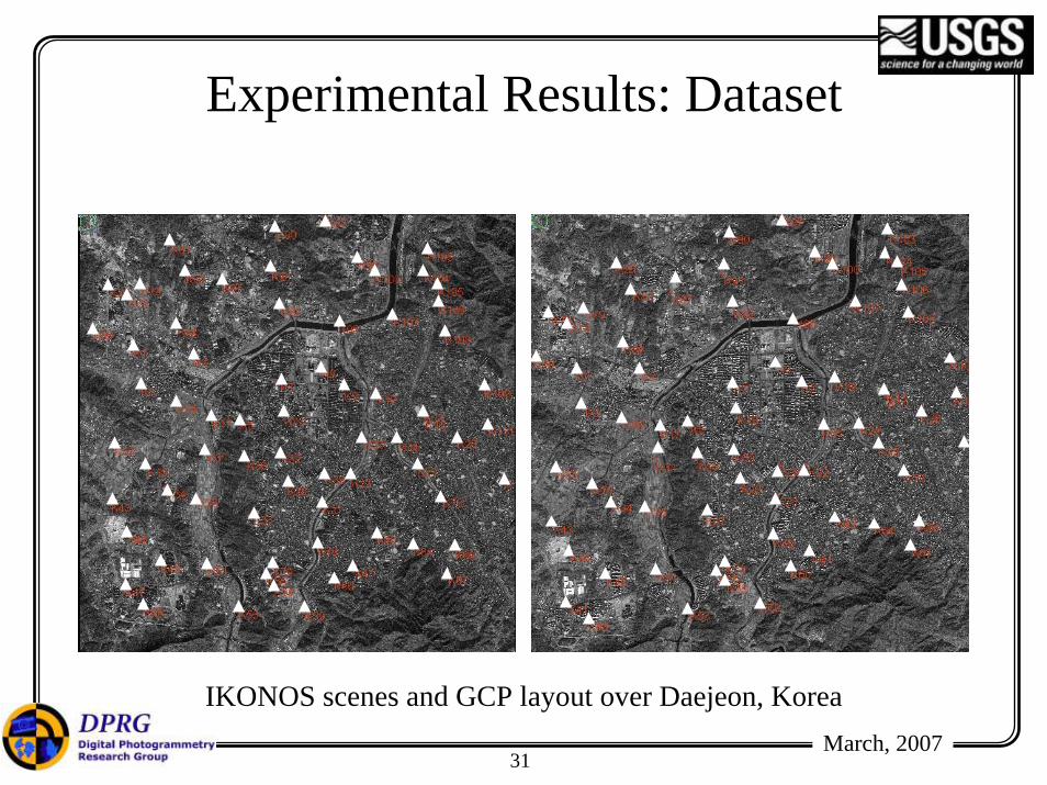
IKONOS scenes and GCP layout over Daejeon, Korea
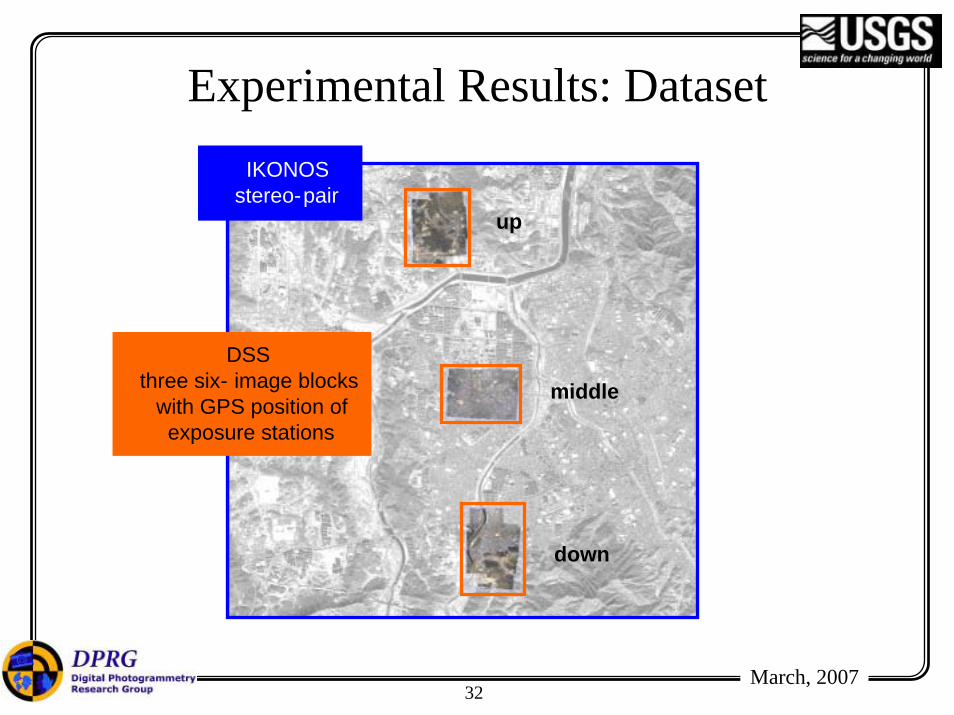
Experimental Results: Dataset
32March, 2007
Experimental Results: DatasetIKONOS
stereo-pair
DSSthree six- image blocks
with GPS position of exposure stations
up
middle
down

33March, 2007
2.1072.0872.01340
2.4632.4133.15215
2.5012.4993.06810
2.5132.5434.0799
2.5793.4173.5918
2.6183.0393.9367
2.7023.3523.6686
2.7274.342N/A5
2.75919.956N/A4
2.86321.322N/A3
3.082N/AN/A2
3.368N/AN/A1
3.066N/AN/A0
DSS GPS
Control PlusControl Points Only
Control Points Only
IKONOS + 18 DSS Frame images
IKONOSonly
# of GCPs
IKONOS + DSS + GPS

34March, 2007
Concluding Remarks• We have a multi-sensor & multi-primitive
triangulation environment.– Sensors: Line cameras, frame cameras, GPS/INS, and
LIDAR.– Primitives: points, lines, and areal features.
• Integrating multi-sensory data in a single triangulation environment will help in:– Reducing the control requirements while maintaining
the reconstruction accuracy.• The output from the triangulation is useful for
orthophoto generation and change detection applications.

35March, 2007
Integration of Lidar and Imagery
Input Imagery (# 27)

36March, 2007
LIDAR DSM + DBM (Four Buildings)Methodologies and Procedures

37March, 2007
DBM (four buildings) has been incorporatedMethodologies and Procedures