Embed Size (px)
Citation preview
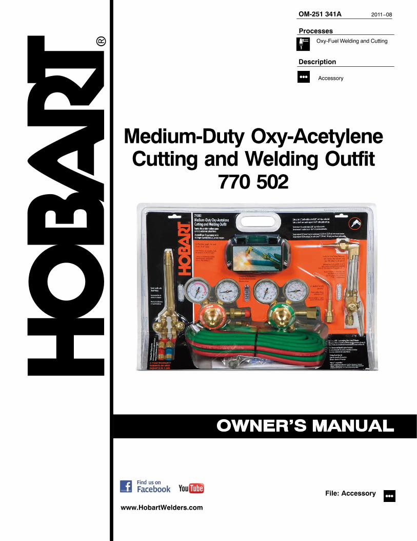
Medium-Duty Oxy-AcetyleneCutting and Welding Outfit
770 502
www.HobartWelders.com
Description
OM-251 341A 2011−08
File: Accessory
Accessory
ProcessesOxy-Fuel Welding and Cutting

Hobart is registered tothe ISO 9001 QualitySystem Standard.
TABLE OF CONTENTS
SECTION 1 − SAFETY PRECAUTIONS - READ BEFORE USING 1. . . . . . . . . . . . . . . . . . . . . . . . . . . . . . . . .1-1 Safety Precautions − Read Before Using 1. . . . . . . . . . . . . . . . . . . . . . . . . . . . . . . . . . . . . . . . . . . . . . . . .1-2 Symbol Usage 1. . . . . . . . . . . . . . . . . . . . . . . . . . . . . . . . . . . . . . . . . . . . . . . . . . . . . . . . . . . . . . . . . . . . . . .
1-3 Oxy-Fuel Welding, Cutting, Brazing, And Heating Hazards 1. . . . . . . . . . . . . . . . . . . . . . . . . . . . . . . . . .1-4 California Proposition 65 Warnings 3. . . . . . . . . . . . . . . . . . . . . . . . . . . . . . . . . . . . . . . . . . . . . . . . . . . . . .1-5 Principal Safety Standards 3. . . . . . . . . . . . . . . . . . . . . . . . . . . . . . . . . . . . . . . . . . . . . . . . . . . . . . . . . . . .
SECTION 2 − SPECIFICATIONS 4. . . . . . . . . . . . . . . . . . . . . . . . . . . . . . . . . . . . . . . . . . . . . . . . . . . . . . . . . . . . . .2-1. Equipment Included With The Kit 4. . . . . . . . . . . . . . . . . . . . . . . . . . . . . . . . . . . . . . . . . . . . . . . . . . . . . . .
2-2. Specifications 4. . . . . . . . . . . . . . . . . . . . . . . . . . . . . . . . . . . . . . . . . . . . . . . . . . . . . . . . . . . . . . . . . . . . . . .2-3. Cutting Tip And Gas Pressure Guide 4. . . . . . . . . . . . . . . . . . . . . . . . . . . . . . . . . . . . . . . . . . . . . . . . . . . .2-4. Welding (Brazing) Tip And Gas Pressure Guide 4. . . . . . . . . . . . . . . . . . . . . . . . . . . . . . . . . . . . . . . . . .
SECTION 3 − INSTALLATION 5. . . . . . . . . . . . . . . . . . . . . . . . . . . . . . . . . . . . . . . . . . . . . . . . . . . . . . . . . . . . . . . .3-1. Installing Regulators On Cylinders 5. . . . . . . . . . . . . . . . . . . . . . . . . . . . . . . . . . . . . . . . . . . . . . . . . . . . . .
3-2. Installing Hoses On Regulators 6. . . . . . . . . . . . . . . . . . . . . . . . . . . . . . . . . . . . . . . . . . . . . . . . . . . . . . . . .3-3. Attaching Hoses To Torch Handle 7. . . . . . . . . . . . . . . . . . . . . . . . . . . . . . . . . . . . . . . . . . . . . . . . . . . . . . .3-4. Attaching Cutting Attachment To Torch Handle 7. . . . . . . . . . . . . . . . . . . . . . . . . . . . . . . . . . . . . . . . . . . .3-5. Installing Cutting Tip On Cutting Attachment 8. . . . . . . . . . . . . . . . . . . . . . . . . . . . . . . . . . . . . . . . . . . . . .3-6. Attaching Welding/Brazing Tip To Torch Handle 8. . . . . . . . . . . . . . . . . . . . . . . . . . . . . . . . . . . . . . . . . . .
3-7. Leak Testing The System 9. . . . . . . . . . . . . . . . . . . . . . . . . . . . . . . . . . . . . . . . . . . . . . . . . . . . . . . . . . . . . .SECTION 4 − OPERATION 10. . . . . . . . . . . . . . . . . . . . . . . . . . . . . . . . . . . . . . . . . . . . . . . . . . . . . . . . . . . . . . . . . .
4-1. Purging Oxygen From The System And Adjusting Oxygen Pressure 10. . . . . . . . . . . . . . . . . . . . . . . . . .4-2. Purging Fuel From The System And Adjusting Fuel Pressure 11. . . . . . . . . . . . . . . . . . . . . . . . . . . . . . . .4-3. Lighting And Using The Cutting Torch 12. . . . . . . . . . . . . . . . . . . . . . . . . . . . . . . . . . . . . . . . . . . . . . . . . . .
4-4. Lighting And Using The Brazing Tip 13. . . . . . . . . . . . . . . . . . . . . . . . . . . . . . . . . . . . . . . . . . . . . . . . . . . . .

OM-251 341 Page 1
SECTION 1 − SAFETY PRECAUTIONS - READ BEFORE USING7
1-1 Safety Precautions − Read Before UsingOXY FUEL 2011−07
Protect yourself and others from injury — read and follow these precautions.
1-2 Symbol Usage
DANGER! − Indicates a hazardous situation which, ifnot avoided, will result in death or serious injury. Thepossible hazards are shown in the adjoining symbolsor explained in the text.
Indicates a hazardous situation which, if not avoided,could result in death or serious injury. The possiblehazards are shown in the adjoining symbols or ex-plained in the text.
NOTICE − Indicates statements not related to personal injury.
� Indicates special instructions.
This group of symbols means Warning! Watch Out! ELECTRICSHOCK, MOVING PARTS, and HOT PARTS hazards. Consult sym-bols and related instructions below for necessary actions to avoid thehazards.
1-3 Oxy-Fuel Welding, Cutting, Brazing, And Heating Hazards
The symbols shown below are used throughout this manualto call attention to and identify possible hazards. When yousee the symbol, watch out, and follow the related instructionsto avoid the hazard. The safety information given below isonly a summary of the more complete safety informationfound in the Safety Standards listed in Section 1-5. Read andfollow all Safety Standards.
Only qualified persons should install, operate, maintain, andrepair this equipment.
During operation, keep everybody, especially children, away.
Do not use this equipment unless you are trained in its properuse or are under competent supervision. Follow the proced-ures described in this booklet every time you use the equip-ment. Failure to follow these instructions may cause fire, ex-plosion, asphyxiation, property damage, or personal injury.This equipment must be used in accordance with all Federal,State, and local regulations as well as DOT (Department ofTransportation) and CGA (Compressed Gas Association)regulations. Contact your gas supplier for more informationon the proper use of compressed gases.
� In this document, the phrase “welding and cutting” also refers to oth-er oxy-fuel operations like brazing and heating.
READ INSTRUCTIONS.
� Read and follow all labels and the Owner’sManual carefully before installing, operating, orservicing equipment. Read the safety informa-tion at the beginning of the manual and in eachsection.
� Use only genuine replacement parts from the manufacturer.
� Perform maintenance and service according to the Owner’sManuals, industry standards, and national, state, and localcodes.
Welding and cutting produces fumes and gases.Breathing these fumes and gases can be hazardousto your health.
FUMES AND GASES can be hazardous.
� Keep your head out of the fumes. Do not breathe the fumes.
� If inside, ventilate the area and/or use local forced ventilation at theflame to remove welding and cutting fumes and gases. Somegases (natural gas and acetylene) are lighter than air and will col-
lect in high areas. Other gases (propane and butane) are heavierthan air and will collect in low areas Heavier-than-air gases aremore difficult to diffuse and are more likely to accumulate.
� If ventilation is poor, wear an approved air-supplied respirator.
� Read and understand the Material Safety Data Sheets (MSDSs)and the manufacturer’s instructions for metals, consumables,coatings, cleaners, and degreasers.
� Work in a confined space only if it is well ventilated, or whilewearing an air-supplied respirator. Always have a trained watch-person nearby. Welding and cutting fumes and gases can displaceair and lower the oxygen level, causing injury or death. Be sure thebreathing air is safe.
� Do not weld or cut in locations near degreasing, cleaning, or spray-ing operations. The heat from welding or cutting flame can reactwith vapors to form highly toxic and irritating gases.
� Do not weld or cut on coated metals, such as galvanized, lead, orcadmium-plated steel unless the coating is removed from the af-fected area, the area is well ventilated, and while wearing an air-supplied respirator. The coatings and any metals containing theseelements can give off toxic fumes if welded or cut.
Welding and cutting on closed containers, such astanks, drums, or pipes, can cause them to blow up.Sparks can fly off from the welding or cuttingoperations. The flying sparks, hot workpiece, and hot
equipment can cause fires and burns. Check and be sure the area issafe before doing any welding or cutting.
WELDING AND CUTTING can causefire or explosion.
� Do not use this welding and cutting equipment with gases otherthan those for which it is intended. Oxygen is not flammable;however, the presence of pure oxygen will drastically increase thespeed and force with which burning takes place. Oxygen mustnever be allowed to contact grease, oil, or other petroleum-basedsubstances; therefore, be sure there is no oil or grease on the regu-lator, cylinder, valves, or equipment. Do not use petroleum-basedpipe sealants. Do not use or store near excessive heat (above125° F/51.5° C) or open flame. Do not refer to oxygen as air and donot use oxygen as a substitute for compressed air. Do not use oxy-gen to clean clothes or work area, for ventilation, or to operatepneumatic tools.
� Inspect all equipment before use. Do not use damaged, defective,or improperly adjusted welding and cutting equipment. Make surelevers and valves work properly, threads on equipment are clean(no grease or oil) and not deformed, gauges are intact and easy toread, regulator is clean and free of oil or dirt, and fittings are prop-erly sized for the cylinder. Make sure hoses are clean (no grease oroil) and ferrules are properly installed so the fitting does not slip in-side the hose. Be sure all connections are tight.

OM-251 341 Page 2
� It is recommended that a reverse-flow check valve or a flashbackarrestor be installed between the torch handle and the regulator.Check valves do not prevent the propagation of a flame upstream(flashback) but are designed to prevent the unintentional backflowof gases into the cutting attachment, torch, hoses, or regulatorwhich could cause an explosion or fire. Do not use a check valvefor large heating or cutting tips. A flashback arrestor can be in-stalled on the torch handle instead of a check valve. A flashbackarrestor is a reverse flow check valve which also prevents thepropagation of a flame upstream. If a flashback arrestor is in-stalled, a check valve is not necessary. Using a flashback arrestorand a check valve may reduce gas flow and affect torch operation.To help prevent the reverse flow of gases, be sure the cylinderscontain enough gas to complete the work.
� Perform work only in an area with a fireproof floor (concrete). Donot heat concrete because it may expand and explode violently.
� Perform work on a fireproof surface. Use heat resistant shields toprotect nearby walls and flooring.
� Do not use if grease or oil is present on equipment or if equipment isdamaged. Have equipment cleaned/repaired by a qualified per-son.
� Do not open a cylinder valve quickly or the regulator may be dam-aged and cause a fire.
� Do not open acetylene cylinder valve more than one turn. (For allgases except acetylene, open cylinder valve fully to backseal thecylinder valve.) Keep cylinder wrench on the cylinder for quickshut-off.
� Do not slightly open or “crack” acetylene cylinder valve to blowdebris from the valve outlet.
� Always purge gas from the system before lighting torch. Purge gasin a well-ventilated area and away from flame or sparks.
� Keep torch flame or sparks away from cylinder, regulator, and gashose.
� Use only acetylene or propane gas and oxygen with this equip-ment.
� Do not use acetylene above 15 psi (103 kPa) static.
� Check oxy-fuel system for leaks with an approved leak detectionsolution or leak detector.
� Remove all flammables within 35 ft (10.7 m) of the welding or cut-ting operation. If this is not possible, tightly cover them with ap-proved covers.
� Do not weld or cut where flying sparks can strike flammable materi-al.
� Protect yourself and others from flying sparks and hot metal.
� Be alert that welding and cutting sparks and hot materials fromwelding and cutting can easily go through small cracks and open-ings to adjacent areas.
� Watch for fire, and keep a fire extinguisher nearby.
� Be aware that welding or cutting on a ceiling, floor, bulkhead, orpartition can cause fire on the hidden side.
� Do not weld or cut on closed containers such as tanks, drums, orpipes, unless they are properly prepared according to AWS F4.1(see Safety Standards).
� Do not weld or cut where the atmosphere may contain flammabledust, gas, or liquid vapors (such as gasoline).
� Wear oil-free protective garments such as leather gloves, heavyshirt, cuffless trousers, high shoes, and a cap.
� Remove any combustibles, such as a butane lighter or matches,from your person before doing any welding or cutting.
� After completion of work, inspect area to ensure it is free of sparks,glowing embers, and flames.
� Follow requirements in OSHA 1910.252 (a) (2) (iv) and NFPA 51Bfor hot work and have a fire watcher and extinguisher nearby.
BUILDUP OF GAS can injure or kill.
� Shut off compressed gas supply when not inuse.
� Always ventilate confined spaces or useapproved air-supplied respirator.
Compressed gas cylinders contain gas under highpressure. If damaged, a cylinder can explode. Sincegas cylinders are normally part of the welding orcutting process, be sure to treat them carefully.
CYLINDERS can explode if damaged.
� Protect compressed gas cylinders from excessive heat, mechani-cal shocks, physical damage, slag, open flames, and sparks.
� Install cylinders in an upright position by securing to a stationarysupport or cylinder rack to prevent falling or tipping. Do not layacetylene cylinders on their sides or acetone will flow out of the cyl-inder and damage the equipment.
� Keep cylinders away from any arc welding, cutting, or other electri-cal circuits.
� Never drape a welding or cutting torch over a gas cylinder.� Never weld or cut on a pressurized cylinder − explosion will result.� Use only correct compressed gas cylinders, regulators, hoses,
and fittings designed for the specific application; maintain themand associated parts in good condition. Do not use compressedgas cylinder unless an approved gas regulator is attached to thegas valve.
� Turn face away from valve outlet when opening cylinder valve. Donot stand in front of or behind the regulator when opening the valve.
� Keep protective cap in place over valve except when cylinder is inuse or connected for use.
� Use the right equipment, correct procedures, and sufficient num-ber of persons to lift and move cylinders.
� Store compressed gas and oxygen cylinders in separate loca-tions.
� Do not modify or repair cylinders or valves. Store leaking acet-ylene cylinders outdoors in a safe area. Identify leaking cylindersand return them to the supplier.
� Read and follow instructions on compressed gas cylinders,associated equipment, and Compressed Gas Association (CGA)publication P-1 listed in Safety Standards.
Light rays from the welding and cutting processproduce intense visible and invisible (ultraviolet andinfrared) rays that can burn eyes and skin. Sparks flyoff from the weld.
LIGHT RAYS can burn eyes and skin.
� Wear approved face protection (helmet or shield) fitted with a prop-er shade of filter lenses to protect your face and eyes from light raysand sparks when welding, cutting, or watching (see ANSI Z49.1and Z87.1 listed in Safety Standards).
� Wear approved safety glasses with side shields under yourhelmet.
� Use protective screens or barriers to protect others from flash,glare and sparks; warn others not to watch the welding or cutting.
� Wear protective clothing made from durable, flame-resistant mate-rial (leather, heavy cotton, or wool) and foot protection.
HOT PARTS can burn.
� Do not touch hot parts bare handed.� Allow cooling period before working on equip-
ment.� To handle hot parts, use proper tools and/or
wear heavy, insulated welding gloves and cloth-ing to prevent burns.
FLYING METAL or DIRT can injure eyes.
� Welding, chipping, wire brushing, and grindingcause sparks and flying metal. As welds cool,they can throw off slag.
� Wear approved safety glasses with sideshields even under your welding helmet.

OM-251 341 Page 3
1-4 California Proposition 65 Warnings
Welding or cutting equipment produces fumes or gaseswhich contain chemicals known to the State of California tocause birth defects and, in some cases, cancer. (CaliforniaHealth & Safety Code Section 25249.5 et seq.)
This product contains chemicals, including lead, known tothe state of California to cause cancer, birth defects, or otherreproductive harm. Wash hands after use.
1-5 Principal Safety Standards
Safety in Welding, Cutting, and Allied Processes, ANSI Standard Z49.1,from Global Engineering Documents (phone: 1-877-413-5184, website:www.global.ihs.com).
Safe Practices for the Preparation of Containers and Piping for Weldingand Cutting, American Welding Society Standard AWS F4.1, from Glob-al Engineering Documents (phone: 1-877-413-5184, website: www.glo-bal.ihs.com).
Safe Handling of Compressed Gases in Cylinders, CGA Pamphlet P-1,from Compressed Gas Association, 4221 Walney Road, 5th Floor,Chantilly, VA 20151 (phone: 703-788-2700, website:www.cganet.com).
Safety in Welding, Cutting, and Allied Processes, CSA StandardW117.2, from Canadian Standards Association, Standards Sales, 5060Spectrum Way, Suite 100, Ontario, Canada L4W 5NS (phone:800-463-6727, website: www.csa-international.org).
Safe Practice For Occupational And Educational Eye And Face Protec-tion, ANSI Standard Z87.1, from American National Standards Institute,25 West 43rd Street, New York, NY 10036 (phone: 212-642-4900, web-
site: www.ansi.org).Standard for Fire Prevention During Welding, Cutting, and Other HotWork, NFPA Standard 51B, from National Fire Protection Association,Quincy, MA 02269 (phone: 1-800-344-3555, website: www.nfpa.org.OSHA, Occupational Safety and Health Standards for General Indus-try, Title 29, Code of Federal Regulations (CFR), Part 1910, Subpart Q,and Part 1926, Subpart J, from U.S. Government Printing Office, Super-intendent of Documents, P.O. Box 371954, Pittsburgh, PA 15250-7954(phone: 1-866-512-1800) (there are 10 OSHA Regional Offices—phone for Region 5, Chicago, is 312-353-2220, website:www.osha.gov).U.S. Consumer Product Safety Commission (CPSC), 4330 East WestHighway, Bethesda, MD 20814 (phone: 301-504-7923, website:www.cpsc.gov).Applications Manual for the Revised NIOSH Lifting Equation, The Na-tional Institute for Occupational Safety and Health (NIOSH), 1600Clifton Rd, Atlanta, GA 30333 (phone: 1-800-232-4636, website:www.cdc.gov/NIOSH).

OM-251 341 Page 4
SECTION 2 − SPECIFICATIONS2-1. Equipment Included With The Kit
! Use only acetylene or propane gasand oxygen with this equipment.
! Flashback arrestor/check valvesare factory installed on the torchhandle. Do not remove these com-ponents.
1 Grade T Oxy-Fuel Hose
2 Regulator − Fuel (Red)
3 Regulator − Oxygen (Green)
4 T-Handle (Two)
5 Cutting Attachment w/Tip
6 Welding (Brazing) Tip
7 Torch Handle
� Torch handle is equipped with flash-back arrestor/check valves.
8 Tank Wrench
9 Spark Lighter
10 Tip Cleaner
11 Welding Goggles
2 3
4
5
678910
1
11
2-2. Specifications
Description Fuel Gas Cutting CapacityWeldingCapacity
Eye Protection Hoses Warranty
Medium DutyOxy-Fuel Cutting
and WeldingEquipment
Acetylene
Propane(with OptionalPropane Tips)
Cuts Materials to1/2 in. (12 mm)Thickness withSupplied Tips
Cuts Materials to6 in. (15 cm)
Thickness withOptional Tips
Welds Materials to3/32 in. (2.4 mm)Thickness withSupplied Tips
Welds Materials to1-1/4 in. (32 mm)Thickness withOptional Tips
Oxy-Fuel Goggle Flip Front
No. 5 Shade2 x 4-1/4 in.
(51 x 108 mm)
Type T3/16 in. ID x 20 ft(4.8 mm x 6 m)
Two-YearLimited
2-3. Cutting Tip And Gas Pressure Guide
Cutting Tip Selection Guide
Tip Size Material Thickness Fuel Gas Pressure Oxygen Pressure
00 1/4 in. (6 mm) 3 − 5 psi (21 − 34 kPa) 20 − 25 psi (138 − 172 kPa)
0 1/2 in. (13 mm) 3 − 5 psi (21 − 34 kPa) 25 − 30 psi (172 − 207 kPa)
1 9/16 in. (14mm) 3 − 5 psi (21 − 34 kPa) 30 − 35 psi (207 − 241 kPa)
2 3/4 in. (19 mm) 3 − 6 psi (21 − 41 kPa) 35 − 40 psi (241 − 276 kPa)
3 1-1/2 in. (38 mm) 4 − 8 psi (28 − 55 kPa) 40 − 45 psi (276 − 310 kPa)
2-4. Welding (Brazing) Tip And Gas Pressure Guide
Welding (Brazing) Tip Selection Guide
Tip Size Material Thickness Fuel Gas Pressure Oxygen Pressure
000 28 − 22 Gauge 3 − 5 psi (21 − 34 kPa) 3 − 5 psi (21 − 34 kPa)
00 22 − 16 Gauge 3 − 5 psi (21 − 34 kPa) 3 − 5 psi (21 − 34 kPa)
0 16 − 14 Gauge 3 − 5 psi (21 − 34 kPa) 3 − 5 psi (21 − 34 kPa)
1 14 − 12 Gauge 4 − 6 psi (28 − 41 kPa) 3 − 5 psi (21 − 34 kPa)
2 12 − 10 Gauge 4 − 6 psi (28 − 41 kPa) 3 − 5 psi (21 − 34 kPa)
3 1/8 − 3/16 in. (3 − 5 mm) 5 − 7 psi (34 − 48 kPa) 3 − 5 psi (21 − 34 kPa)

OM-251 341 Page 5
SECTION 3 − INSTALLATION
3-1. Installing Regulators On Cylinders
! Do not slightly open or“crack” fuel cylinder valve toblow debris from the valveoutlet.
! Do not use petroleum-basedpipe sealants.
! Use only acetylene or propanegas and oxygen with thisequipment.
� Brass to brass connections gen-erally do not require pipe seal-ant.
1 Oxygen Regulator(Green Label)
2 Fuel Regulator(Red Label)
� The hex nut on the fuel regulatorhas notches on the corners. Thehex nut corners are smooth onthe oxygen regulator.
Install the two-piece fitting of theoxygen regulator (green) on the cor-responding fitting on the oxygencylinder. The oxygen cylinder hasright-hand (clockwise) threads. Usesupplied wrench to tighten hex nut.
Install the two-piece fitting of the fuelregulator (red) on the fuel cylinder(acetylene or propane only). The fuelcylinder has left-hand (counterclock-wise) threads. Use supplied wrenchto tighten hex nut.
� Contact the gas supplier if theregulator fittings do not matchthe cylinder fittings.
3 Working Pressure Gauge4 Cylinder Pressure Gauge
Each regulator has two gauges. Thegauge closest to the cylinder showsthe pressure in the cylinder. Theother gauge shows the outlet pres-sure going to the torch handle.
Tools Needed:
Pipe Sealant
1
2
3
4
1 in.

OM-251 341 Page 6
! Use only industrial gradehose. Grade T hose (suppliedwith kit) is acceptable for allfuel gases. Grade R hose is foracetylene only.
1 Regulator2 Hose
3 Adjustment Handle
Connect green hose to the regulatoron the oxygen cylinder. Connect redhose to the regulator on the fuel gascylinder.
� The fuel fittings have left-handedthreads.
Use supplied wrench to tighten fit-tings.
NOTICE − Before opening the cylin-der valves, turn regulator adjustingscrews all the way out to releasepressure on the regulator dia-phragm. Pressure may damage theregulators.
Stand with the oxygen cylinder valvebetween you and the regulator.Slowly open the oxygen cylindervalve 1/4 turn until the tank pressurestabilizes, then fully open the oxygenvalve to seat it in the open position.
Tighten the adjustment handle (onthe regulator adjustment screw) tobring the pressure up to 5 psi (34kPa). Allow oxygen to flow throughhose for about 10 seconds. Stopoxygen flow by turning adjustmenthandle counterclockwise.
Stand with the fuel cylinder valvebetween you and the regulator.Slowly open the fuel cylinder valve1/4 turn until the tank pressure stabil-izes, then open the fuel valve to amaximum of one full turn (acetylene)or fully open (all other fuel gases).Leave wrench on cylinder so cylindercan be shut off quickly.
Tighten the adjustment handle (onthe regulator adjustment screw) tobring the pressure up to 5 psi (34kPa). Allow fuel gas to flow throughhose for about 10 seconds. Stop fuelgas flow by turning adjustmenthandle counterclockwise.
Tools Needed:
Pipe Sealant
3-2. Installing Hoses On Regulators
11/16 in.
1
2
3

OM-251 341 Page 7
3-3. Attaching Hoses To Torch Handle
! Do not use petroleum-basedpipe sealants.
! Flashback arrestor/checkvalves are factory installed onthe torch handle. Do not re-move these components.
� The hex nut on the fuel hose hasnotches on the corners. The hexnut corners are smooth on theoxygen hose.
1 Torch Handle2 Fuel Hose (Red)
3 Oxygen Hose (Green)
Attach fuel hose (red) to fuel inletfitting on torch handle. The nut on thefuel hose has left-hand threads.
Attach oxygen hose (green) to oxy-gen inlet fitting on torch handle. Thenut on the oxygen hose has righthand threads.
Use supplied wrench to tighten con-nections.
Tools Needed:
Pipe Sealant
1
2
3
11/16 in.
3-4. Attaching Cutting Attachment To Torch Handle
! Do not use petroleum-basedpipe sealants.
� See Section 3-6 for attachingbrazing tip to torch handle.
1 Cutting Attachment
2 Torch Handle
The cutting attachment uses twoo-rings to seal the connection to thetorch handle. If replacing the cuttingattachment, be sure the o-rings areproperly installed.
Attach cutting attachment to torchhandle.
Use supplied wrench to tightenconnections.
Tools Needed:
Pipe Sealant
1 2
3/4 in.

OM-251 341 Page 8
3-5. Installing Cutting Tip On Cutting Attachment
! Do not use petroleum-basedpipe sealants.
Cutting tips are available in differ-ent sizes to accommodate variousmetal thicknesses. Use the table inSection 2-3 to select the correct tip,and to determine the correct fueland oxygen pressures.
� A No. 0 cutting tip is already in-stalled in the cutting attach-ment.
1 Cutting Tip
2 Cutting Attachment
Install correct cutting tip in cuttingattachment.
Use supplied wrench to tightenconnections.
Tools Needed:
Pipe Sealant
1 2
1 in.
3-6. Attaching Welding/Brazing Tip To Torch Handle
! Do not use petroleum-basedpipe sealants.
Welding/brazing tips are availablein different sizes to accommodatevarious metal thicknesses. Use thetable in Section 2-3 to select thecorrect tip, and to determine thecorrect fuel and oxygen pressures.
� A No. 0 welding/brazing tip withmixer is supplied with the kit.
1 Welding/Brazing Tip WithMixer
2 Torch Handle
Attach welding/brazing tip to torchhandle.
Use supplied wrench to tightenconnections.
Tools Needed:
Pipe Sealant
1 2
3/4 in.

OM-251 341 Page 9
3-7. Leak Testing The System
! Leak test the system beforelighting the torch. Repeatthis procedure every timethe equipment is set up or acylinder is changed.
1 Fuel Regulator AdjustmentHandle
2 Oxygen Regulator AdjustmentHandle
3 Torch Handle Fuel Valve
4 Torch Handle Oxygen Valve
5 Oxygen Cylinder Valve
6 Fuel Cylinder Valve
Turn the fuel and oxygen regulatoradjustment handles to the Off posi-tion (counterclockwise).
Close the fuel and oxygen valveson the torch handle.
Slowly open the oxygen cylindervalve one turn and adjust pressureto 20 psi (138 kPa) by turningadjustment handle clockwise.
Slowly open the fuel cylinder valveand adjust pressure to 10 psi (69kPa).
Using an approved leak detectionsolution or leak detector, checkevery connection from the cylindervalve to the torch tip. Correct allleaks before using equipment.
Close cylinder valves.
Tools Needed:
Pipe Sealant
1 6
2 5
43
11/16, 3/4, 1 in.

OM-251 341 Page 10
SECTION 4 − OPERATION
4-1. Purging Oxygen From The System And Adjusting Oxygen Pressure
! Always purge gas from thesystem before lighting thetorch.
� Purging the system is neces-sary to remove mixed gas fromthe equipment.
� See Sections 2-3 and 2-4 foroxygen and fuel pressure re-commendations.
Purging Oxygen And SettingPressure
1 Oxygen Cylinder Valve
2 Torch Handle Oxygen Valve
3 Preheat Oxygen Valve
4 Oxygen Regulator AdjustmentHandle
Slowly open the oxygen cylindervalve until valve is fully open.
Open oxygen valve on torch 1/4turn for five to ten seconds. (If usingwelding attachment, also open pre-heat oxygen valve.) While the oxy-gen is flowing, turn the adjustmenthandle on the oxygen regulator toachieve the desired working pres-sure.
Close the oxygen valve and thepreheat oxygen valve on the torchhandle.
Purge fuel from the system andadjust fuel pressure according toSection 4-2.
Tools Needed:
4 1
23

OM-251 341 Page 11
4-2. Purging Fuel From The System And Adjusting Fuel Pressure
! Always purge gas from thesystem before lighting thetorch.
� Purging the system is neces-sary to remove mixed gas fromthe equipment.
� See Sections 2-3 and 2-4 foroxygen and fuel pressure re-commendations.
� Purge oxygen from the systemaccording to Section 4-1.
Purging Fuel And Setting FuelPressure
1 Fuel Cylinder Valve
2 Torch Handle Fuel Valve
3 Preheat Oxygen Valve
4 Fuel Regulator AdjustmentHandle
Slowly open the fuel cylinder valveone turn maximum (for acetylene).Fully open fuel cylinder valve for allother fuel gases.
Open fuel valve on torch 1/4 turn forfive to ten seconds. (If using weld-ing attachment, also open preheatoxygen valve.) While the fuel isflowing, turn the adjustment handleon the fuel regulator to achieve thedesired working pressure.
Close the fuel valve and the preheatoxygen valve on the torch handle.
Tools Needed:
4 1
3 2

OM-251 341 Page 12
4-3. Lighting And Using The Cutting Torch
! Always purge gas from the systembefore lighting torch. See Sections4-1 and 4-2.
� See Sections 2-3 and 2-4 for oxygenand fuel pressure recommendations.
� See Sections 4-1 and 4-2 for informa-tion on adjusting oxygen and fuel pres-sure.
1 Spark Lighter
2 Oxygen Valve
3 Preheat Oxygen Valve
4 Fuel Valve
5 Cutting Lever
Lighting The Torch
Hold the spark lighter near the torch tip.
Slowly open the fuel valve on the torchhandle 1/4 turn and quickly squeeze thespark lighter to light the flame.
Slowly open the oxygen valve on the torchto the desired pressure.
Continue to open the fuel valve until theblack sooty smoke disappears and theflame begins to move away from the tip.Slowly open the preheat oxygen valve onthe cutting attachment; a white-hot feather(flame) appears.Slowly add oxygen until the feather beginsto disappear into the bright cone at the endof the tip. This produces a neutral flame(ratio of fuel to oxygen is 1:1).Using The Cutting TorchHold the torch tip about 1/4 in. (6 mm) fromthe metal to be cut.Heat the metal until it is bright red (about1550° F or 843° C).Slowly depress the cutting lever on thecutting attachment. Let the oxygen streamburn through the metal, then completelydepress the lever to begin the cuttingprocess.When Finished CuttingNOTICE − Shut down the torch in the cor-rect sequence or the torch may be dam-aged. Oxygen must be released from the
system first or residual fuel in the handle orfuel hose may burn. Fuel cannot burnwithout oxygen.When finished cutting, release the cuttinglever. Close the oxygen preheat valve onthe torch handle first and then close the fuelvalve on the torch handle.Close valves at fuel and oxygen cylinders.Open the fuel valve on the torch handle torelieve pressure; both gauges on the fuelregulator should show no pressure. Closethe fuel valve on the torch handle.Turn fuel regulator adjustment handlecounterclockwise until there is no pressureon the regulator diaphragm.Open the preheat oxygen valve on thetorch handle to relieve pressure; bothgauges on the oxygen regulator shouldshow no pressure. Close the preheat oxy-gen valve and oxygen valve on the torchhandle.Turn oxygen regulator adjustment handlecounterclockwise until there is no pressureon the regulator diaphragm.
Tools Needed:
1
23 45

OM-251 341 Page 13
4-4. Lighting And Using The Brazing Tip
! Always purge gas from the systembefore lighting torch. See Sections4-1 and 4-2.
! Do not allow the flame to touch thebrazing tip or allow the brazing tip tooverheat.
� See Sections 2-3 and 2-4 for oxygenand fuel pressure recommendations.
� See Sections 4-1 and 4-2 for informa-tion on adjusting oxygen and fuel pres-sure.
1 Spark Lighter2 Oxygen Valve3 Fuel Valve
Lighting The Torch
Hold the spark lighter near the torch tip.
Slowly open the fuel valve on the torch
handle about 1/8 turn and quickly squeezethe spark lighter to light the flame.
Slowly open the oxygen valve on the torchto neutralize the flame.
Open the fuel valve on the torch handleanother 1/8 turn and then increase theoxygen to neutralize the flame.
Continue this procedure until the maximumamount of fuel gas is used and the desiredflame is present.
When Finished Welding/Brazing
NOTICE − Shut down torch in correct se-quence or the torch may be damaged.Oxygen must be released from the systemfirst or residual fuel in the handle or fuelhose may burn. Fuel cannot burn withoutoxygen.
When finished welding/brazing, close theoxygen valve on the torch handle first and
then close the fuel valve on the torchhandle.
Close valves at fuel and oxygen cylinders.
Open the fuel valve on the torch handle torelieve pressure; both gauges on the fuelregulator should show no pressure. Closethe fuel valve on the torch handle.
Turn fuel regulator adjustment handlecounterclockwise until there is no pressureon the regulator diaphragm.
Open the oxygen valve on the torch handleto relieve pressure; both gauges on theoxygen regulator should show no pressure.Close the oxygen valve on the torchhandle.
Turn oxygen regulator adjustment handlecounterclockwise until there is no pressureon the regulator diaphragm.
Tools Needed:
1
23

Resources AvailableAlways provide Model Name and Serial/Style Number.
To locate a Service Center:Call 1-800-332-3281or visit our website at www.HobartWelders.com/wheretobuy
For Technical Assistance:Call 1-800-332-3281 7 AM to 5 PM EST − Monday through Friday
ORIGINAL INSTRUCTIONS − PRINTED IN USA © 2011 Hobart Welding Products. 2011−01
Hobart Welding ProductsAn Illinois Tool Works Company600 West Main StreetTroy, OH 45373 USA
For Assistance:Call1-800-332-3281
Model Name Serial/Style Number
Purchase Date (Date which equipment was delivered to original customer.)
Distributor
Address
City
State Zip
Please complete and retain with your personal records.
Owner’s Record
Thank you for purchasing Hobart. Our trained technical support team isdedicated to your satisfaction. For questions regarding performance, op-eration, or service, contact us!