Embed Size (px)
Citation preview

www.ccsenet.org/cis Computer and Information Science Vol. 4, No. 6; November 2011
ISSN 1913-8989 E-ISSN 1913-8997 2
Medical Images Compression Using Modified SPIHT Algorithm and Multiwavelets Transformation
Muna F. Al-Sammaraie
Management Information System Department
Faculty of Economics and Administrative Sciences
Al-Zaytoonah University, Amman, Jordan
P. O. Box 130, Amman 11733, Jordan
E-mail: [email protected]
Received: September 30, 2011 Accepted: October 17, 2011 Published: November 1, 2011
doi:10.5539/cis.v4n6p2 URL: http://dx.doi.org/10.5539/cis.v4n6p2
Abstract
Recently, the wavelet transform has emerged as a cutting edge technology within the field of image compression research. Wavelet methods involve overlapping transforms with varying-length basis functions. This overlapping nature of the transform alleviates blocking artifacts, while the multi-resolution character of the wavelet decomposition leads to superior energy compaction and perceptual quality of the decompressed image. Over the past decade, the success of wavelets in solving many different problems has contributed to its unprecedented popularity. Due to implementation constraints scalar wavelets do not posses all the properties which are needed for better performance in compression. New class of wavelets called ‘Multiwavelets’ which posses more than one scaling filters overcomes this problem. The objective of this paper is to develop an efficient compression scheme and to obtain better quality and higher compression ratio through multiwavelet transform and embedded coding of multiwavelet coefficients through Set Partitioning In Hierarchical Trees algorithm (SPIHT) algorithm. A comparison of the best known multiwavelets is made to the best known scalar wavelets. An adaptive image-coding algorithm for compression of medical images in the wavelet domain is presented. Both quantitative and qualitative measures of performance are examined for Medical images. The objective (based on PSNR) and subjective (perceived image quality) results of these simulations are presented.
Keywords: Multiwavelet, Medical image compression, Wavelet transform, Image Quality, SPIHT
1. Introduction
Compression of medical images to reduce their storage and transmission bandwidth requirements is of great interest in the implementation of systems such as PACS (picture archival and communication system) and teleradiology. Recently, the subband or wavelet coding has proven to be a very useful framework for loss compression of medical images (Gupta, N., Swamy, M.N.S., & Plotkin, E., 2005; Chiu, E., Vaisey, J., & Atkins, S. 2001; Li, X., Hu, G., & Gao, S., 1999).
However, the compression will reduce the image fidelity, especially when the images are compressed at lower bit rates. The reconstructed images suffer from blocking artifacts and the quality of the image is severely degraded under the circumstances of high compression ratio, which is shown by the JPEG standard. In recent years, much of the research activities in image coding have been focused on the discrete wavelet transform (DWT) as the overlapping nature of the transform alleviates blocking artifacts, while the multi-resolution character of the wavelet decomposition leads to superior energy compaction and perceptual quality of the decompressed image. Furthermore, the multi-resolution transform domain means that wavelet compression methods degrade much more gracefully than block-DCT methods as the compression ratio increases. As a result, a new International Standard for image coding called JPEG2000 was introduced in September 2001. This introduction has meant that for the first time, the discrete wavelet transform is to be used for the decomposition and reconstruction of images together with an efficient coding scheme. The aim of multi-resolution analysis is simultaneous image representation on different resolution level. This kind of representation is well suited to the properties of Human Visual System (HVS) (Jayant, N., Johnson, J. & Safranek, R., 1993).
More recently, the wavelet transform has emerged as a cutting edge technology, within the field of image compression. Wavelet-based coding provides substantial improvements in picture quality at higher compression

www.ccsenet.org/cis Computer and Information Science Vol. 4, No. 6; November 2011
Published by Canadian Center of Science and Education 3
ratios. Over the past few years, a variety of powerful and sophisticated wavelet-based schemes (Soman K.P & Ramachandran K.I., 2004; Mallat S., 1998) for image compression, have been developed and implemented. For better performance in compression, filters used in wavelet transforms should have the property of orthogonality, symmetry, short support and higher approximation order. Due to implementation constraints scalar wavelets do not satisfy all these properties simultaneously (Vasily Strela, et al., 1999; Vetterli.M & G. Strang, 1994). New class of wavelets called ‘Multiwavelets’ which posses more than one scaling filters (Geronimo.J, D. Hardin, & P. R. Massopust, 1994) overcomes this problem. Thus multiwavelets offer the possibility of superior performance and high degree of freedom for image processing applications, compared with scalar wavelets. Multiwavelets can achieve better level of performance than scalar wavelets with similar computational complexity.
2. Methodology
2.1 Image Compression
A common characteristic of most images is that the neighboring pixels are correlated and therefore contain redundant information. The foremost task then is to find less correlated representation of the image. Two fundamental components of compression are redundancy and irrelevancy reduction. Redundancy reduction aims at removing duplication from the signal source (image/video). Irrelevancy reduction omits parts of the signal that will not be noticed by the signal receiver, namely the Human Visual System. In general, three types of redundancy can be identified:
Spatial Redundancy or correlation between neighboring pixel values.
Spectral Redundancy or correlation between different color planes or spectral bands.
Temporal Redundancy or correlation between adjacent frames in a sequence of images (in video applications).
The Compression techniques are classified as Lossy/Lossless Compression and Predictive/Transform Compression.
A. Lossless vs. Lossy Compression: In lossless compression schemes, the reconstructed image, after compression, is numerically identical to the original image. However lossless compression can only achieve a modest amount of compression. An image reconstructed following lossy compression contains degradation relative to the original. Often this is because the compression scheme completely discards redundant information. However, lossy schemes are capable of achieving much higher compression. Under normal viewing conditions, no visible loss is perceived (visually lossless)
B. Predictive vs. Transform coding: In predictive coding, information already sent or available is used to predict future values, and the difference is coded. Since this is done in the image or spatial domain, it is relatively simple to implement and is readily adapted to local image characteristics. Differential Pulse Code Modulation (DPCM) is one particular example of predictive coding. Transform coding, on the other hand, first transforms the image from its spatial domain representation to a different type of representation using some well-known transform and then codes the transformed values (coefficients). This method provides greater data compression compared to predictive methods, although at the expense of greater computation.
2.2 Wavelet Coding
Wavelet coding is a form of data compression well suited for image compression and the goal is to store image data in as little space as possible in a file. Wavelet compression can be either lossless or lossy. Using a wavelet transform the wavelet compression methods are adequate for representing transients, such as percussion sounds in audio, or high-frequency components in two-dimensional images, for example an image of stars on a night sky. This means that the transient elements of a data signal can be represented by a smaller amount of information than would be the case if some other transform, such as the more widespread discrete cosine transform, had been used First a wavelet transform is applied. This produces as many coefficients as there are pixels in the image (i.e.: there is no compression yet since it is only a transform). These coefficients can then be compressed more easily because the information is statistically concentrated in just a few coefficients. This principle is called transform coding. After that, they are quantized and the quantized values are entropy coded and/or run length coded. JPEG 2000 is a wavelet based coding scheme. In encoding the image and its components are decomposed into rectangular tiles. Wavelet transform is applied on each tile. After quantization sub bands of coefficients are collected into rectangular array of code blocks. Certain ROI is encoded with high image quality. Markers are added in the bit stream to avoid error resilience.

www.ccsenet.org/cis Computer and Information Science Vol. 4, No. 6; November 2011
ISSN 1913-8989 E-ISSN 1913-8997 4
Research on JPEG coding (ISO/IEC 14495-1) has proved that JPEG-LS is simple and easy to implement. It consumes less memory and is faster than JPEG 2000 though JPEG 2000 supports progressive transmission. Given index of image of interest along Z axis, only concerned portion of the bit-stream is decoded at desired quality. Selective data to access can be improved by splitting image into regions corresponding objects. A scheme based on the three-dimensional (3-D) discrete cosine transform (DCT) has been proposed for volumetric data coding (Schelkens, et al., 2003). These techniques fail to provide lossless coding coupled with quality and resolution scalability, which is a significant drawback for medical applications.
Hence new compression methods evolved exploiting the quad tree and block-based coding concepts, layered zero-coding principles, and context-based arithmetic coding. Additionally, a new 3-D DCT-based coding scheme is designed and used for benchmarking. The proposed wavelet-based coding algorithms produce embedded data streams that can be decoded up to the lossless level and support the desired set of functionality constraints. Moreover, objective and subjective quality evaluation on various medical volumetric datasets shows that the proposed algorithms provide competitive lossy and lossless compression results when compared with the state-of the-art. A wavelet based coding system featuring object based 3D encoding with 2D decoding capabilities was proposed in (G.Meganez, & L.Grewe, 2004). In this the improvement in coding efficiency provided by 3D algorithms can be obtained at a lower computational cost where each object is encoded independently to generate a self contained segment of bit stream. The implementation of the DWT via lifting steps scheme in the non linear integer version and the embedding of the encoded information allow reconstructing each object of each image at a progressive up to lossless quality. Bordered artifacts are avoided by encoding some extra coefficients for each object. A new image compression algorithm, based on independent embedded block coding with optimized truncation of the embedded bit-streams (EBCOT) was proposed where the algorithm (D. Taubman., 2000) exhibits state-of-the-art compression performance while producing a bit-stream with a rich set of features, including resolution and SNR scalability together with a “random access” property.
The algorithm has modest complexity and is suitable for applications involving remote browsing of large compressed images. The algorithm lends itself to explicit optimization with respect to MSE as well as more realistic psycho visual metrics, capable of modeling the spatially varying visual masking phenomenon.
2.3 Multiwavelets
Multiwavelets are defined using several wavelets with several scaling functions (Geronimo.J, D. Hardin, & P. R. Massopust, 1994). Multiwavelets have several advantages in comparison with scalar wavelet (Strang.G & V. Strela, 1995). The features such as compact support, Orthogonality, symmetry, and high order approximation are known to be important in signal processing. A scalar wavelet can not possess all these properties at the same time (Strang. G & T. Nguyen, 1995). On the other hand, a multiwavelet system can simultaneously provide perfect reconstruction while preserving length (Orthogonality), good performance at the boundaries (via linear-phase symmetry), and a high order of approximation (vanishing moments) (JPEG2000 Overview).
Thus multiwavelets offer the possibility of superior performance and high degree of freedom for image processing applications, compared with scalar wavelets. A multiwavelet with r scaling functions and r wavelet functions is said to have multiplicity r. When r = 1, one scaling function and one wavelet function, the multiwavelet system reduces to the scalar wavelet system. Multiwavelets have two or more scaling functions and wavelet functions. For notational difference the set of scaling functions can be written using the vector notation
Tr tttt )](.......)(),([)( 21 Where, )(t is called the multi-scaling function. Likewise the
multiwavelet function is defined from the set of wavelet function Tr tttt )](.......)(),([)( 21 When
r=1, )(t is called a scalar wavelet or simply called wavelet. Multiwavelets differ from scalar wavelet systems
in requiring two or more input streams to the multiwavelet filter bank. Multiwavelets are an extension of the scalar wavelet to the vector case. As in the scalar wavelet case, the theory of multiwavelets is based on the idea of multiresolution analysis (MRA). The difference is that multiwavelets have several scaling functions. For multiwavelets, the notion of MRA is the same except that now a basis for V0 and V1 is generated by translates of N scaling functions )(,).........(2),(1 ktNktkt .
The multi scaling function and the multiwavelet function will satisfy matrix dilation as in the following
equations.
k k ktHt )2(2)(
k k ktGt )2(2)(

www.ccsenet.org/cis Computer and Information Science Vol. 4, No. 6; November 2011
Published by Canadian Center of Science and Education 5
The filter coefficients Hk and Gk are N by N matrices instead of scalar. Corresponding to each multiwavelet system, there is a matrix-valued multi-rate filter bank. A multiwavelet filter bank has “taps” that are N × N matrices. The 4-coefficient symmetric multiwavelet filter bank whose low pass filter is given by the four N × N matrices named C. Unlike a scalar 2-band Para unitary filter bank, the corresponding high pass filter specified by the four N × N matrices named D, cannot be obtained simply as an “alternating flip” of the low pass filter; the wavelet filters D must be designed. The resulting N channel, N × N matrix filter bank operates on N input data streams, filtering them into 2N output streams, each of which is down sampled by a factor of 2. This is shown in Figure 1.
Each row of the multi-filter is a combination of N ordinary filters, each operating on the separate data stream.
Some reasons for potentially choosing multiwavelets are summarized below.
1. The extra degrees of freedom inherent in multiwavelets can be used to reduce restrictions on the filter properties.
1. Symmetric filters are necessary for symmetric signal extension.
2. Orthogonality makes the transform easier to design and implement.
3. In contrast to the limitations of scalar wavelets, multiwavelets are able to possess the best of all these properties simultaneously.
2. One desirable feature of any transform used in image compression is the amount of energy compaction achieved. A filter with good energy compaction properties can decorrelate a fairly uniform input signal into a small number of scaling coefficients containing most of the energy and a large number of sparse wavelet coefficients. This becomes important during the quantization since the wavelet coefficients are represented with significantly fewer bits on average than the scaling coefficients. Therefore better performance is obtained when the wavelet coefficients have values clustered about zero with little variance, to avoid as much quantization noise as possible Thus multiwavelets have the potential to offer better reconstructive quality at the same bit rate.
2.4 Medical images analysis
The image content being viewed influences the perception of quality irrespective to technical parameters of the system. Due to this reason, the content of our test medical images should be understood first. There are three modalities of medical images that have been identified in this project, which includes X-Ray, CT scan and ultrasound images (Grgic, S., Grgic, M. L. & Zovko-Cihlar, B, 2001). Spectral activity of test images is evaluated using DCT applied to the whole image. DCT coefficients as a result of DCT show frequency content of the image. Figure 2 shows the distributions of image values before and after DCT for some of the test images. The distribution of DCT coefficients depends on image content (black dots represent DCT coefficients; arrows indicate the increase of horizontal and vertical frequency). We can see that the X-Ray image has the lowest spectral activity compare to CT image with moderate spectral activity and ultrasound image with high spectral activity.
From our observation, we realized that different modalities of medical image have different characteristics, i.e., noise, texture, intensity profile, etc. In other words, our test images are with different spatial and frequency characteristics.
From the analysis on histogram of the image, we learn more about the dynamic range of each image (also each modality) as well as the type of image. Basically, the histogram of a digital image represents the discrete function of the number of gray level and the number of pixels in an image. From Figure 2(A), we see that the components of the histogram of the CT scan images are concentrated on the low (left) side of the gray scale. This is true since CT scan images are considered dark image. On the contrary, the components of the histogram for ultrasound images are biased toward the high (right) side of the gray scale because they are bright images. X-ray images cover a broad range of the gray scale compared to the other two modalities. This indicates that X-ray images are high in contrast.
2.5 Quality Measurements
Two of the quality measurements used to compare the various image compression techniques are the Mean Square Error (MSE) and the Peak Signal to Noise Ratio (PSNR).
The MSE is the cumulative squared error between the compressed and the original image, whereas PSNR is a measure of the peak error. The mathematical formulae for the two are

www.ccsenet.org/cis Computer and Information Science Vol. 4, No. 6; November 2011
ISSN 1913-8989 E-ISSN 1913-8997 6
Error E = Original image – Reconstructed image
MSE = E / (Size of Image)
PSNR =20 log 10 (255/√MSE)
A lower value for MSE means lesser error, and as seen from the inverse relation between the MSE and PSNR, this translates to a high value of PSNR. Logically, a higher value of PSNR is good because it means that the ratio of Signal to Noise is higher. Here, the 'signal' is the original image, and the 'noise' is the error in reconstruction. So, a compression scheme having a lower MSE (and a high PSNR), can be recognized as a better one. Wavelet-based coding is more robust under transmission and decoding errors, and also facilitates progressive transmission of images In addition; they are better matched to the Human Visual System characteristics. Because of their inherent multi resolution nature, wavelet coding schemes are especially suitable for applications where scalability and tolerable degradation are important.
3. Proposed Algorithm
For evaluating the effectiveness of the Multiwavelet transform for coding images or videos at low bit rates, an effective quantization and embedded coding of coefficients has been realized. An embedded coding is applied to transformed image in order to take the advantage of the decorrelation properties of its coefficients.
Some of the embedded coding schemes are embedded image coding using zero trees of Wavelet coefficients (EZW), and SPIHT.
The SPIHT coder is a powerful image compression algorithm that produces an embedded bit stream from which the best reconstructed images can be obtained at various bit rates. This algorithm improves the perceptual quality of the image at all the bit rates. The Modified SPIHT algorithm for Multiwavelet differs from the ordinary SPIHT algorithm by the way in which the subsets are partitioned and significant information is conveyed which is shown in Figure 3.
A tree structure, called spatial orientation tree, defines the spatial relationship on the hierarchical pyramid. Figure 3 shows how spatial orientation tree is defined for Multiwavelet coefficients.
The proposed algorithm illustrate in the following steps:
Step 1:
The wavelet and multiwavelet transformations are directly applicable only to one dimensional signal. But images are two dimensional signals, so we must find a way to process them with a 1-D transform. The two main categories of methods for doing this are separable and non-separable algorithms.
Separable methods simply work on each dimension in series. The typical approach is to process each of the rows in order and then process each column of the result (Vetterli.M & G. Strang, 1994). Nonseparable methods, such as the factored scalar wavelet method work in both dimensions at the same time. While nonseparable methods can offer benefits over separable methods, such as a savings in computation, they are generally more difficult to implement.
Step 2:
Multiwavelet filter banks require a vector-valued input signal. First split each row or column into two half-length signals, and then use these two half signals as the channel inputs into the multifilter. This approach is to simply take the odd samples for one signal and the even samples for the second signal. This approach does not work well because it destroys the assumed characteristics of the input signal. The prefilter step adjusts the input signal properties so that one scalar signal is split in to two half-length signals in such a way that the orders of approximation built into the multifilter are utilized. The prefiltering is generally performed by taking the two signals as a 2 X N matrix (where the original 1-D signal has length 2N) and then left-multiplying by one or more 2 X 2 prefilter matrices.
Step 3:
In practice all signals have finite length, so we must devise techniques for filtering such signals at their boundaries. Symmetric extension of the data is used. It has been shown that symmetric extension is the best way to handle signal boundaries. Symmetric extension preserves signal continuity, but can be implemented only with linear-phase (symmetric and/or antisymmetric) filter banks. Symmetric extension is useful for image compression applications.

www.ccsenet.org/cis Computer and Information Science Vol. 4, No. 6; November 2011
Published by Canadian Center of Science and Education 7
Step 4:
Since multiwavelets decomposition produce two low pass subbands and two high pass subbands in each dimension, the organization and statistics of multiwavelets subbands differ from the scalar wavelet case. During a single level of decomposition using a scalar wavelet transform, the 2-D image data is replaced with four blocks corresponding to the subbands representing either low pass or high pass in both dimensions. The Multiwavelets decomposition subbands are shown in Figure 4. The multiwavelets used here have two channels, so there will be two sets of scaling coefficients and two sets of multiwavelets coefficients. Since the multiple iterations over the low pass data are desired, the scaling coefficients for the two channels are stored together. Likewise, the wavelet coefficients for the two channels are also stored together. For example, the subband labeled L1H2 corresponds to data from the second
Channel high pass filter in the horizontal direction and the first channel low pass filter in the vertical direction. In practice, more than one level of decomposition is performed on the image. Successive decompositions are performed on the low pass coefficients from the previous stage to further reduce the number of low pass coefficients.
The multiwavelet decompositions iterate on the low pass coefficients from the previous decompositions, as shown in Figure 5 In the case of scalar wavelets, the low pass quarter image is a single subband. But when the multiwavelet transform is used, the quarter image of low pass coefficients is actually a 2x2 block of subbands (the L1L1, L1L2, L2L1 and L2L2 subbands in Fig). Due to the nature of the preprocessing and symmetric extension method, data in these different subbands becomes inter mixed during iteration of the multiwavelets transform. The inter mixing of the multiwavelet low pass subbands leads to suboptimal results.
Step 5:
As shown in Figures 6 and 7. Set Partitioning Sorting
progressive selection of coefficients such that
2,1,,2| 000, nnnnc nji
Significance Test
otherwise
cUs
nji
Ujin
,0
2max,1)( ,
),(
Basic Algorithm
– select partitions of pixels Um
– for each n = n0, n0 - 1, n0 - 2, ...
• if Sn(Um) = 0 (the set is insignificant) then disregard pixels in Um
• if Sn(Um) = 1 (the set is significant) then use recursive algorithm to partition Um
– test sets until all significant coefficients found
– The following sets of coordinates are used to present the new coding method:
O (i, j): set of coordinates of all offspring of node (i, j)
D (i, j): set of coordinates of all descendants of node (i, j)
H (i, j): set of coordinates of all spatial orientation tree roots (nodes in the highest pyramid level)
L (i, j): D(i, j) – O(i, j) (all descendents except the offspring)
– Three Lists
• LIP - list of insignificant pixels
• LIS - list of tree roots (i, j) of insignificant descendant sets D(i, j) (Type A) or insignificant descendant of offspring sets L(i, j) = D(i, j) - O(i, j) (Type B)
• LSP - list of significant pixels
– Lists tested in order LIP, LIS, LSP for efficient embedded coding
– initialization of Lists
• LIP: co-ordinates of all tree roots

www.ccsenet.org/cis Computer and Information Science Vol. 4, No. 6; November 2011
ISSN 1913-8989 E-ISSN 1913-8997 8
wavelet example: co-ordinates in coarsest scale subband
• LIS: co-ordinates of all tree roots with nonempty desendent trees
wavelet example: co-ordinates in coarsest scale subband pointing to descendant trees
• LSP: empty
– Sorting Pass
– Refinement Pass
• Output n-th bit of all LSP members found significant at thresholds greater than 2 n
• Two bit types in stream: significance test bits and refinement bits
– Quantization Step Update:
• Decrement the value of n by 1 and go to sorting pass if n is not less than 0
4. Experimental Results and Discussions
In this experiment, we compressed each medical image from different modalities by using all wavelets mentioned above. The compression process was done at different bit rates (0.25-2). All these images were grayscale images with depth 8 bits-per-pixel. The findings were rated according to objective as well as subjective evaluations, which the former was quantified by PSNR measurement.
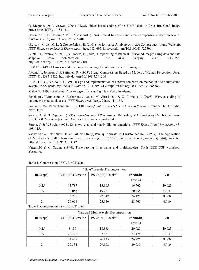
The Multiwavelet filters used in this work were “GHM” pair of multifilters, orthogonal symmetric/antisymmetric multifilter “Sa4”, Cardinal 3-balanced orthogonal multifilter “Cardbal3”. The Table-1 shows the results of the Comparison of PSNR values under the decomposition levels 2, 3, 4 using HAAR wavelet.
Table 2 to Table 4 shows the Comparison of PSNR values under decomposition levels 2, 3, 4 using the Multiwavelets “Cardbal3”, “GHM”, “SA4 for the CT scan Image.
Whenever the decomposition Levels gradually increases the PSNR values are also increasing. Figure 8 shows that an increase in the PSNR values for the increase in the decomposition levels for wavelets.
As presented in the Experiment Theory, the image content may influence the performance of the multiwavelet. In other words, the choice of multiwavelet in a compression process is image dependent. For Ct scan, we found the decomposition of level-2 was the best as it gave the highest and consistent PSNR values at all compression bit rates.
For X-ray images, the best performing multiwavelet with decomposition of level-3 in both objective and subjective measures. The difference of the performance of wavelet filters was bigger than in the CT scan case.
For ultrasound images, we can see that the Haar wavelet performed the best; it gave the highest PSNR values at all compression bit rate.
The visual quality of the reconstructed image was also studied. Figures 9–11 illustrate the visual perception for test images from different modalities at various compression rates using the best performing wavelet. Generally, when the PSNR is 40 dB or larger, the two images are virtually indistinguishable by human observers. In this case, we can see that at 0.5 bpp, the reconstructed image is almost identical to the original.
5. Conclusion
The performance of Multiwavelets in general depends on the Image characteristics. For the Images with mostly low frequency content, (Ordinary still images) scalar wavelets generally give better performance. However multiwavelets appear to excel at preserving high frequency content. In particular, multiwavelets better capture the sharp edges and geometric patterns that occur in images. As Medical Images are normally high frequency patterns Multiwavelets provide better PSNR even at the higher values Compression Ratio. Cardinal 3 balance multiwavelets shows very good performance since they have very balanced orthogonal properties which are essential for signal processing applications.
References
Chiu, E., Vaisey, J., & Atkins, S. (2001). Wavelet-based space-frequency compression of ultrasound images. IEEE Trans. Inf. Technol. Biomed., 5(4), 300–310. http://dx.doi.org/10.1109/4233.966105
D. Taubman. (2000). High performance scalable image compression with EBCOT. IEEE Trans. Image, 9(7), 1158-1170.
www.ccsenet.org/cis Computer and Information Science Vol. 4, No. 6; November 2011
Published by Canadian Center of Science and Education 9
G. Meganez, & L. Grewe. (2004). 3D/2D object based coding of head MRI data. in Proc. Int. Conf. Image processing (ICIP), 1, 181-184.
Geronimo J., D. Hardin, & P. R. Massopust. (1994). Fractal functions and wavelet expansions based on several functions. J. Approx. Theory, 78, 373-401.
Grgic, S., Grgic, M. L. & Zovko-Cihlar, B. (2001). Performance Analysis of Image Compression Using Wavelets. IEEE Trans, on industrial Electronics, 48(3), 682–695. http://dx.doi.org/10.1109/41.925596
Gupta, N., Swamy, M. N. S., & Plotkin, E. (2005). Despeckling of medical ultrasound images using data and rate adaptive lossy compression. IEEE Trans. Med. Imaging, 24(6), 743–754. http://dx.doi.org/10.1109/TMI.2005.847401
ISO/IEC 14495-1 Lossless and near lossless coding of continuous tone still images.
Jayant, N., Johnson, J. & Safranek, R. (1993). Signal Compression Based on Models of Human Perception. Proc. IEEE, 81, 1385–1422. http://dx.doi.org/10.1109/5.241504
Li, X., Hu, G., & Gao, S. (1999). Design and implementation of a novel compression method in a tele-ultrasound system. IEEE Trans. Inf. Technol. Biomed., 3(3), 205–213. http://dx.doi.org/10.1109/4233.788582
Mallat S. (1998). A Wavelet Tour of Signal Processing. New York: Academic.
Schelkens, PMunteanu, A. Barbarien, J. Galca, M. Giro-Nieto, & X. Cornelis. J. (2003). Wavelet coding of volumetric medical datasets. IEEE Trans. Med. Imag., 22(3), 441-458.
Soman K. P & Ramachandran K. I. (2004). Insight into Wavelets from Theory to Practice. Prentice Hall Of India, New Delhi.
Strang. G & T. Nguyen. (1995). Wavelets and Filter Banks. Wellesley, MA: Wellesley-Cambridge Press. JPEG2000 Overview. [Online] Available: http:\\www.purdue.edu
Strang. G & V. Strela. (1995). Short wavelets and matrix dilation equations. IEEE Trans. Signal Processing, 43, 108–115.
Vasily Strela, Peter Niels Heller, Gilbert Strang, Pankaj Topiwala, & Christopher Heil. (1999). The Application of Multiwavelet Filter banks to Image Processing. IEEE Transactions on image processing, 8(4), 548-563. http://dx.doi.org/10.1109/83.753742
Vetterli.M & G. Strang. (1994). Time-varying filter banks and multiwavelets. Sixth IEEE DSP workshop, Yosemite.
Table 1. Compression PSNR for CT scan
“Haar” Wavelet Decomposition
Rate(bpp) PSNR(dB) Level=2 PSNR(dB) Level=3 PSNR(dB)
Level-4
CR
0.25 13.787 13.905 16.762 40.023
0.5 14.053 19.261 20.438 13.247
1 16.786 22.342 24.121 8.000
2 20.098 25.150 28.765 4.010
Table 2. Compression PSNR for CT scan
Cardbal3 MultiWavelet Decomposition
Rate(bpp) PSNR(dB) Level=2 PSNR(dB) Level=3 PSNR(dB)
Level-4
CR
0.25 8.189 18.883 20.925 40.023
0.5 20.425 22.651 23.124 13.247
1 24.459 26.135 26.876 8.000
2 27.334 29.108 29.935 4.010

www.ccsenet.org/cis Computer and Information Science Vol. 4, No. 6; November 2011
ISSN 1913-8989 E-ISSN 1913-8997 10
Table 3. Compression PSNR for CT scan
GHM MultiWavelet Decomposition
Rate(bpp) PSNR(dB) Level=2 PSNR(dB) Level=3 PSNR(dB)
Level-4
CR
0.25 8.675 13.226 13.804 40.023
0.5 13.561 15.032 15.541 13.247
1 16.448 19.216 19.803 8.000
2 22.712 25.710 26.104 4.010
Table 4. Compression PSNR for CT scan
SA4 MultiWavelet Decomposition
Rate(bpp) PSNR(dB) Level=2 PSNR(dB) Level=3 PSNR(dB)
Level-4
CR
0.25 3.345 3.870 4.654 40.023
0.5 5.661 10.535 11.859 13.247
1 15.155 17.622 17.934 8.000
2 25.655 27.762 30.666 4.010
Figure 1. Multi-rate Filter bank

www.ccsenet.org/cis Computer and Information Science Vol. 4, No. 6; November 2011
Published by Canadian Center of Science and Education 11
Figure 2. (A) CT Scan image (i) Original image (ii) DCT distribution (iii) Image histogram

www.ccsenet.org/cis Computer and Information Science Vol. 4, No. 6; November 2011
ISSN 1913-8989 E-ISSN 1913-8997 12
Figure 2. (B) X-ray image (i) Original image (ii) DCT distribution (iii) Image histogram

www.ccsenet.org/cis Computer and Information Science Vol. 4, No. 6; November 2011
Published by Canadian Center of Science and Education 13
Figure 2. (C) Ultrasound image (i) Original image (ii) DCT distribution (iii) Image histogram

www.ccsenet.org/cis Computer and Information Science Vol. 4, No. 6; November 2011
ISSN 1913-8989 E-ISSN 1913-8997 14
Figure 3. Scanning and quantization order of subimages of Multiwavelet decomposition
Figure 4. One –Level Decomposition Figure 5. Two-Level Decomposition

www.ccsenet.org/cis Computer and Information Science Vol. 4, No. 6; November 2011
Published by Canadian Center of Science and Education 15
Figure 6. The Flowchart of SPIHT Sorting Pass
1) For each entry (i,j) in the LIP do:
1. Output Sn (i ,j )
2. If Sn (i ,j )=1, then move (i,j) to the LSP and output the sign of Ci,j
2) For each entry (i,j) in the LIS do:
3. If the entry is of type A then
4. Output Sn (D(i,j))
5. If Sn (i,j )=1 then for each (k,l)∈O(i,j) do:
6. Output Sn(k,l)
7. If Sn(k,l) =1 then add (k,l) to the LSP and output the sign of Ck,l
8. If Sn(k,l) =0 then add (k,l) to the end of LIP
9. If Li,j ≠ φ then move (i, j) to the end of the LIS as entry of type B, and go to step 2) b); otherwise remove
entry from the LIS.
10. If the entry is of type B then
11. Output Sn(L(i, j))
12. If Sn(L(i,j))=1 then
13. add each (k,l)∈O(i,j) to the end of the LIS as entry of type A
14. remove (i,j) from the LIS
Figure 7. The Algorithm of SPIHT Sorting Pass

www.ccsenet.org/cis Computer and Information Science Vol. 4, No. 6; November 2011
ISSN 1913-8989 E-ISSN 1913-8997 16
Figure 8. Comparison of PSNR values for 3 levels of decomposition using “HAAR” wavelet for CT scan
Figure 9. Visual perception of X-ray image using Cardlab3 multiwavelet at different compression bit rates.
Figure 10. Visual perception of CT scan image using GHM multiwavelet at different bit rates.

www.ccsenet.org/cis Computer and Information Science Vol. 4, No. 6; November 2011
Published by Canadian Center of Science and Education 17
Figure 11. Visual perception of Ultrasound image using SA4 multiwavelet at different bit rates


![[1913] #2.12 Armour's Monthly Cook Book - October 1913](https://img.dokumen.tips/doc/110x75/577d2da61a28ab4e1eae0102/1913-212-armours-monthly-cook-book-october-1913.jpg)


