Embed Size (px)
Citation preview

THE
DESIGNR A T I O N A L E
History of Total Knee Arthroplasty
Design Features of the ADVANCE® Medial-Pivot Knee
Kinematicsof the Medial-Pivot Knee
Size & Stature
Stability of a Ball-in-Socket Knee
Wear
Patient Preference
ADVANCE®
Medial-Pivot Knee System

Total Knee Arthroplasty - A History
The Story
Design Features
Kinematics
Stature
Stability
Wear
Patient Preference
3-7
8-9
10-15
16-18
19-21
22-23
24-26
27
ADVANCEMedial-Pivot Knee System
®

ADVANCE® Medial-Pivot Knee System
3
the prosthetic components must work in concert with existing ligaments and provide normal kinematics and function in cases where ligaments are compromised or sacrificed. It is particularly important to maintain the function provided by the posterior cruciate ligament (PCL). This can be achieved either by retain-ing the ligament or by substituting for it using a post and cam mechanism or a raised anterior lip.
Knee replacements have made leaps and bounds from their inception and continue to surpass previous designs.
How did we get where we are now?
The history of total knees may be traced back as far as 1860, when Gluck fashioned a crude total knee of ivory that featured a simple hinge. The device allowed only a limited angle of rotation and motion in a single direction. Gluck’s hinge yielded great strength, but was not biocompatible. Over the next 100 years, the knee was thought to behave according to this simple hinge design. It was not until the mid 1960s when research-ers and surgeons again turned their attention to total knee replacements. During this time, the kinematic assumptions in knees had changed; no longer did researchers believe the knee was a simple hinge. As the knee has many critical geometrical characteristics, researchers thought the two cruciate ligaments and the two leg bones formed a very sophisticated and precise mechanism, called a four-bar link. Many total knee designs were based around this rationale. This four-bar link mechanism of the knee is shown at various stages of rotation in FIguRE 1.
One important feature of the four-bar link theory is that the instantaneous center of rotation coincides with the cross-over point of the cruciate ligaments. This cross-over point moves as the joint flexes and extends so the knee does not have a fixed point of rotation that is found in a simple hinge joint.
Figure 1 | Four-Bar Link Theory
Total Knee Arthroplasty - A History
ADVANCE® Medial-Pivot Knee
The theory states the knee joint is a particularly sophisticated kind of four-bar link, because the cruciate ligaments are not rigid and have to be kept taut by the rolling action of the bones.
It was not until the release of the ICLH Knee, which was designed by Drs. Freeman and Swanson, that the four-bar link was discredited. Their implant relied heavily on component
In kneereplacements,
FEMuR
TIBIA
PCL ACL
ADVANCE® Medial-Pivot Knee System
4
geometry, and retaining soft tissue balance and both cruciate ligaments to provide stability. However, this design, although great in theory, experienced complications including instability, prosthetic loosening, and patellofemoral abnormalities. These issues and other complications resulted in a revision rate of 28.5%, naming instability as the major cause.1
Due to the complications within the patellofemoral joint, subsequent designs in the 1970s improved fixation and introduced patellofemoral joint replacement options. The Total Condylar Knee, developed by Dr. John Insall, was the first prosthetic design aimed at solving both of these issues. Insall’s device featured a round-on-round geometry in both the coronal and sagittal planes. This design touted partial conformity, which aimed at providing mediolateral stability. Fixation was improved by adding a central stem to the tibial base that ran down the center of the tibial canal. Insall’s first attempt featured an all-polyethylene base, and it was not until the mid-1970s that a cobalt chromium baseplate was introduced. Although a design much ahead of its time, axial compression tests would later show failure of the prosthesis.2
Later in the 1970s the first mobile-bearing knee was created. Its designers, Drs. Buechel and Pappas, aimed to design a mobile-bearing, metal-backed knee system with low constraint forces and low contact stresses which would allow normal joint articulation and loading. The result was the New Jersey Knee, or as it later became known, the LCS (Low Contact Stress) Mobile-Bearing Knee. At that time, fixed-bearing designs had been unable to provide mobility while eliminating unnecessary constraint forces. Buechel and Pappas believed a mobile-bearing prosthesis would eliminate unnecessary constraint forces and produce low constraint forces and low contact stresses. By doing so, surgical misalignment may be corrected, and both intraoperative adjustment of the joint space and postoperative replacement of the bearings may be carried out without disturbing the fixation of the device.3 However, complications with the LCS Knee included bearing dislocation, bearing breakage and an increase in polyethylene wear. 4
Even if all the ligaments are healthy, it may be advantageous to sacrifice the cruciate ligaments and substitute their function through features of an implant. This approach was originally introduced to increase the amount of exposure available to the surgeon to make it easier to properly prepare the fixation surfaces. Many femoral components featured sagittal plane geometry that approximated the shape of
The 1980s were also a changing time for the orthopaedic community. Many orthopaedic companies began designing total knee replacements with expanded sizing options to fit patients’ needs. These companies touted complete interchangeability to suit the differences in femoral and tibial geometry. There was also a major push toward creating instrumentation that aided in making total knee procedures easily repeatable. There was also an increasing need to create the most natural-feeling knee possible; however, little kinematic research had been performed to study natural knee motion.
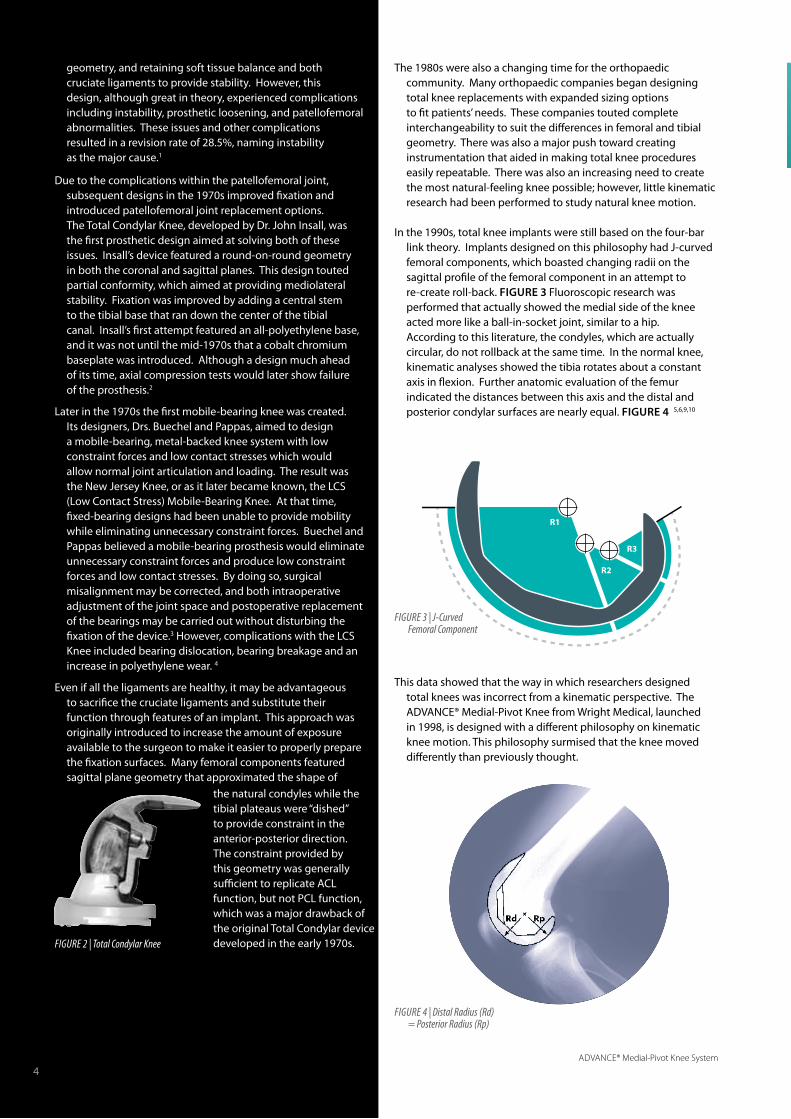
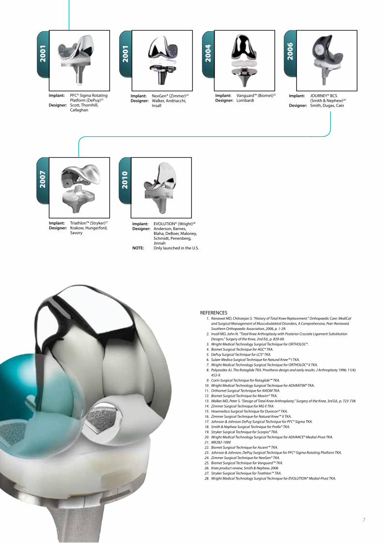
In the 1990s, total knee implants were still based on the four-bar link theory. Implants designed on this philosophy had J-curved femoral components, which boasted changing radii on the sagittal profile of the femoral component in an attempt to re-create roll-back. FIguRE 3 Fluoroscopic research was performed that actually showed the medial side of the knee acted more like a ball-in-socket joint, similar to a hip. According to this literature, the condyles, which are actually circular, do not rollback at the same time. In the normal knee, kinematic analyses showed the tibia rotates about a constant axis in flexion. Further anatomic evaluation of the femur indicated the distances between this axis and the distal and posterior condylar surfaces are nearly equal. FIguRE 4 5,6,9,10
This data showed that the way in which researchers designed total knees was incorrect from a kinematic perspective. The ADVANCE® Medial-Pivot Knee from Wright Medical, launched in 1998, is designed with a different philosophy on kinematic knee motion. This philosophy surmised that the knee moved differently than previously thought.
Figure 2 | Total Condylar Knee
R1
R2
R3
Figure 3 | J-Curved Femoral Component
the natural condyles while the tibial plateaus were “dished” to provide constraint in the anterior-posterior direction. The constraint provided by this geometry was generally sufficient to replicate ACL function, but not PCL function, which was a major drawback of the original Total Condylar device developed in the early 1970s.
Figure 4 | Distal radius (rd) = Posterior radius (rp)
4

ADVANCE® Medial-Pivot Knee System
5
The History of
Total Knee ArthroplastyThis timeline offers an overview of the genealogy of the total knee systems from every major orthopaedic company.
Countless total knees have been designed throughout the years. Those most frequently referenced are listed here.
1978
1982
1971
1971
1958
1968
1968
Implant: Ivory Hinge1
Designer: GluckImplant: Walldius Hinge1
Designer: WalldiusImplant: Polycentric Knee1, 2
Designer: GunstonImplant: Duocondylar Knee1, 2
Designer: Ranawat, Insall, Shine
Implant: ICLH1
Designer: Freeman, SwansonImplant: Geometric (Howmedica, now Stryker)1, 2
Designer: Turner, Coventry
1860
1972
1972
Implant: Anatomic Knee (DePuy)1, 2
Designer: Townley
1974
Implant: Total Condylar Knee1, 2
Designer: Insall, Walker, Ranawat
1975
Implant: New Jersey Knee, aka Low Contact Stress (LCS) Mobile Bearing Knee1, 2
Designer: Buechel, Pappas
Implant: Insall-Burstein (I/B®) PS Knee (Zimmer)2
Designer: Insall, Burstein
Implant: ORTHOLOC® (Wright)3
Designer: Whiteside
Implant: University of California Irvine (UCI) Knee (Wright)1
Designer: Waugh

ADVANCE® Medial-Pivot Knee System
6
1994
1995
1997
1996
1983
1988
1984
1989
1990
1991
1985
1987
Implant: AGC® (Biomet)4
Designer: Ritter & DanielImplant: LCS® Total Knee System (DePuy)5
Designer: Buechel, Pappas
Implant: Natural Knee™ I (Sulzer Medica, now Zimmer)2, 6
Designer: Hoffman
Implant: Rotaglide® 8, 9
Designer: WilsonImplant: ADVANTIM® Modular (Wright)10
Designer: Whiteside
Implant: AXIOM® (ORTHOMET, now Wright)11
Designer: Hood & Kennedy
Implant: Duracon® (Howmedica, now Stryker)13, 15
Designer Borden, Habermarin, Hedley, Hungerford, Krackow
Implant: Natural Knee™ II (Sulzer Medica, now Zimmer)16
Designer: Hoffman
Implant: PFC® (DePuy)13, 17
Designer: Scott, Thornhill, Ranawat
1996
Implant: Scorpio® (Stryker)19
Designer: Becker, Antonio, Incavo, LotkeImplant: Profix® (Smith & Nephew)18
Designer: Whiteside
Implant: ADVANCE® Medial-Pivot20
Designer: Blaha, Maloney, Schmidt
1998
Implant: Ascent™ (Biomet)22
Designer: Bassett, Jacobs
1998
Implant: MG II (Zimmer)13, 14
Designer: Miller, Galante
1991
Implant: ORTHOLOC® II (Wright)7
Designer: Whiteside
Implant: Maxim® (Biomet)12
Designer: Lombardi, Vaughn
ADVANCE® Medial-Pivot Knee System
7
REFERENCES 1. Ranawat MD, Chitranjan S. “History of Total Knee Replacement.” Orthopaedic Care: MediCal
and Surgical Management of Musculoskeletal Disorders, A Comprehensive, Peer-Reviewed. Southern Orthopaedic Association, 2006, p. 1-29.
2. Insall MD, John N. “Total Knee Arthroplasty with Posterior Cruciate Ligament Substitution Designs.” Surgery of the Knee, 2nd Ed., p. 829-69.
3. Wright Medical Technology Surgical Technique for ORTHOLOC®. 4. Biomet Surgical Technique for AGC® TKA. 5. DePuy Surgical Technique for LCS® TKA. 6. Sulzer Medica Surgical Technique for Natural Knee™ I TKA. 7. Wright Medical Technology Surgical Technique for ORTHOLOC® II TKA. 8. Polyzoides AJ. The Rotaglide TKA. Prosthesis design and early results. J Arthroplasty 1996; 11(4):
453-9. 9. Corin Surgical Technique for Rotaglide™ TKA. 10. Wright Medical Technology Surgical Technique for ADVANTIM® TKA. 11. Orthomet Surgical Technique for AXIOM TKA. 12. Biomet Surgical Technique for Maxim® TKA. 13. Walker MD, Peter S. “Design of Total Knee Arthroplasty.” Surgery of the Knee, 3rd Ed., p. 723-738. 14. Zimmer Surgical Technique for MG II TKA. 15. Howmedica Surgical Technique for Duracon® TKA. 16. Zimmer Surgical Technique for Natural Knee™ II TKA. 17. Johnson & Johnson DePuy Surgical Technique for PFC® Sigma TKA. 18. Smith & Nephew Surgical Technique for Profix® TKA. 19. Stryker Surgical Technique for Scorpio® TKA. 20. Wright Medical Technology Surgical Technique for ADVANCE® Medial-Pivot TKA. 21. MK282-1000 22. Biomet Surgical Technique for Ascent™ TKA. 23. Johnson & Johnson, DePuy Surgical Technique for PFC® Sigma Rotating Platform TKA. 24. Zimmer Surgical Technique for NexGen® TKA. 25. Biomet Surgical Technique for Vanguard™ TKA. 26. Knee product review, Smith & Nephew, 2006 27. Stryker Surgical Technique for Triathlon™ TKA. 28. Wright Medical Technology Surgical Technique for EVOLUTION® Medial-Pivot TKA.
2007
2001
2004
2006
2010
Implant: NexGen® (Zimmer)24
Designer: Walker, Andriacchi, Insall
Implant: Vanguard™ (Biomet)25
Designer: LombardiImplant: JOURNEY® BCS (Smith & Nephew)26
Designer: Smith, Dugas, Cain
Implant: Triathlon™ (Stryker)27
Designer: Krakow, Hungerford, Savory
Implant: EVOLUTION® (Wright)28
Designer: Anderson, Barnes, Blaha, DeBoer, Maloney, Schmidt, Penenberg, JinnahNOTE: Only launched in the U.S.
2001
Implant: PFC® Sigma Rotating Platform (DePuy)23
Designer: Scott, Thornhill, Callaghan

ADVANCE® Medial-Pivot Knee System
8ADVANCE® Medial-Pivot Knee System
Many patients complain of a loss of stability
due to total knee replacement, and this is sometimes called anterior femoral sliding. In the literature this is referred to as “paradoxical motion.” This term was made prominent by Rick Komistek, PhD, who is a prominent fluoroscopic researcher. This femoral sliding or “paradoxical motion” may be caused by an increased flexion gap or total knee incongruity from an implant that was designed to allow rollback.1,2
In general, total knees may reduce the natural stability of the knee. Instead of rolling back, the femoral component slides anteriorly. This is considered a paradox because total knees are designed to rollback, but instead they slide forward. In a typical total knee replacement, as the knee goes into flexion at approximately 20°, the weight of the body pushes the femur forward along the tibia. The femur will continue to slide forward until it’s stopped by the PCL or remaining musculature. Furthermore, this sliding forward puts added stress on the remaining soft tissues.
This “paradoxical motion” is also present in posterior-stabilized knees.1,2 Many surgeons believe that posterior-stabilized knees are unable to slide forward due to the post and cam articulation. This has been shown in the literature to be false. Posterior-stabilized total knee replacements slide forward until they contact the post. In terms of the four-bar link theory, once the cam engages the post, the rotational axis of a traditional posterior-stabilized knee becomes the post.
The MRI images shown in FIguRES 1 and 2 are visual examples of how the normal knee moves.3 These were MRIs provided as part of a study from Mr. Michael Freeman, a British surgeon, and Vera Pinskerova, a Czechoslovakian PhD. The medial compartment of the tibial plateau is concave and “rocks” from a relatively posterior contact to anterior contact. FIguRE 1 The meniscus, the center of the contact area and the penetration point of the flexion axis, moves forward with extension, but the medial femoral condyle does not.3-5
Unlike the medial side, the lateral meniscus moves forward with the femur during extension. Thus, the tibiofemoral contact area also moves forward with extension resulting in an arcuate zone of contact. FIguRE 2
Figure 1 | Medial compartment
Figure 2 | Lateral compartment
ADVANCE® Medial-Pivot
The Story
8

ADVANCE® Medial-Pivot Knee System
9
The ADVANCE® femoral implant has a constant sagittal radius of curvature extending from full extension to 90 degrees flexion. FIguRE 6 The curvature values for each femoral implant were chosen from a detailed analysis of 130 cadaveric femora performed by Dr D. Blaha. In the study, the radius of curvature of the femur was measured between the average flexion-extension axis and the distal surface of the femur every 10 degrees to 90 degrees flexion.6 The ADVANCE® Medial-Pivot Knee also matches the sagittal radius with the radius in the coronal plane to create the partial sphere of the femoral components. FIguRE 5
In the sagittal plane the femoral component also features a smaller closing radius which has been shown to increase range of motion.7 FIguRE 7
To further increase range of motion, the shape of the femoral component is complemented by the anterior stability of the ADVANCE® Medial-Pivot tibial inserts. These components provide a robust anterior lip which maintains the femoral component in the posterior third of the articular surface. FIguRE 8 This creates a long quadriceps lever arm and reduces anterior sliding in flexion.1
There are several features in the normal knee that make it stable: the musculature, capsule, collateral ligaments, the ACL, and PCL. Nearly 60% of body weight is transferred through the medial side of the knee. The medial side of the tibial plateau is concave in shape and, along with the medial intercondylar eminence, acts to prevent anterior translation of the medial femoral condyle. The opposite is true, however, for the lateral compartment of the knee. This side is convex in shape and, coupled with a “humped” intercondylar eminence, allows arcuate translation. These structures create a knee that is more stable on the medial side than the lateral side. Differences in stability led to the concept of medial-pivot kinematics. FIguRE 3
Figure 4 | Medial-Pivot insert
Figure 5 | The ADVANCe® femur features spheri-cal femoral condyles
Figure 3 | Superior view of the tibial plateau
PCL stops anterior slide
ACL stopsposterior slide
Lateral meniscusallows motion
Medial meniscus and concave surface provide stability
CB D
A
Medial posterior lipreplaces ACL andstops posterior slide
Medial meniscal“socket” providesstability
Medial anterior lip replaces PCL and stops anterior slide
Lateral meniscalpath allows for 15°of motion
Figure 7 | Smaller closing radius
Figure 6 | Constant radius from 0° to 90° flexion
Figure 8 | Femoral position of ADVANCe® Medial-Pivot Knee
A medial-pivoting tibial insert is provided in the ADVANCE® Knee System, designed to reproduce the rotational and translational kinematics of the normal knee. On the lateral side there is an arcuate path, which allows 15° of motion around a medial-pivot point. That pivot point is on the medial side and is provided by a spherical concave surface. The anterior lip is designed to prevent anterior slide, while the posterior lip is designed to replace the ACL and prevent posterior slide. FIguRE 4
Closing Radius
0˚30˚
60˚
90˚
1/3 A-P
A-P
REFERENCES 1. Komistek R. In vivo fluoroscopic analyses of
the normal human knee. Clin Orthop Relat Res. 2003;410:69-81.
2. Schmidt R. Fluoroscopic analyses of cruciate retaining and medial pivot knee implants. Clin Orthop Relat Res. 2003;410:139-147.
3. Freeman M. The movement of the normal tibiofemoral joint. J Biomechanics. 2005;38:197-208.
4. Pinskerova V. Knee imaging study sheds new light on fl exion, rollback. Orthopaedics Today. 1999.
5. Freeman. The movement of the knee studied by magnetic resonance imaging. Clin Orthop Relat Res. 2003;410:35-43.
6. Blaha JD. Using the transepicondylar axis to defi ne the sagittal morphology of the distal part of the femur. JBJS 2002; 84:S48-55.
7. Iwaki et al, JBJS 82-B, n°8 (2000): 1189-95
ADVANCE® Medial-Pivot Knee System
10
ADVANCE® Medial-Pivot
DesignFeatures
ADVANCE® Medial-Pivot Knee System
11
ADVANCE® Medial-Pivot Femoral Component
Constant Radius
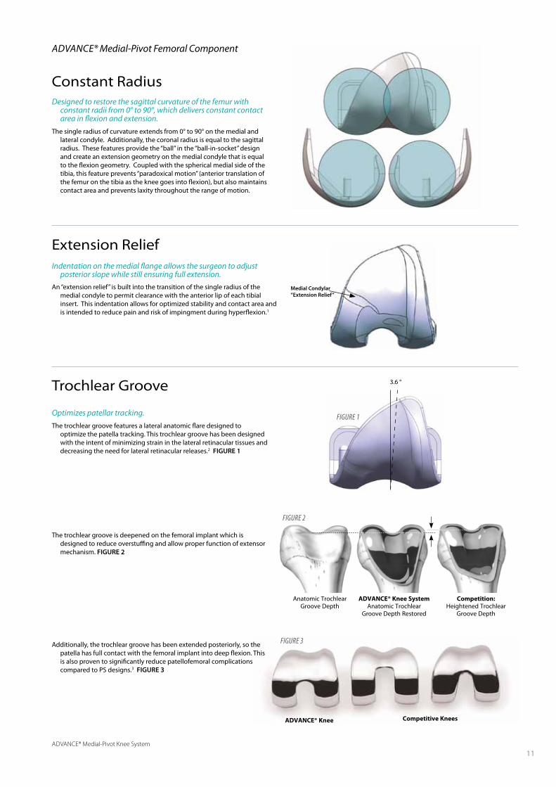
Optimizes patellar tracking.
The trochlear groove features a lateral anatomic flare designed to optimize the patella tracking. This trochlear groove has been designed with the intent of minimizing strain in the lateral retinacular tissues and decreasing the need for lateral retinacular releases.2 FIguRE 1
The trochlear groove is deepened on the femoral implant which is designed to reduce overstuffing and allow proper function of extensor mechanism. FIguRE 2
Additionally, the trochlear groove has been extended posteriorly, so the patella has full contact with the femoral implant into deep flexion. This is also proven to significantly reduce patellofemoral complications compared to PS designs.3 FIguRE 3
Indentation on the medial flange allows the surgeon to adjust posterior slope while still ensuring full extension.
An “extension relief” is built into the transition of the single radius of the medial condyle to permit clearance with the anterior lip of each tibial insert. This indentation allows for optimized stability and contact area and is intended to reduce pain and risk of impingment during hyperflexion.1
Designed to restore the sagittal curvature of the femur with constant radii from 0° to 90°, which delivers constant contact area in flexion and extension.
The single radius of curvature extends from 0° to 90° on the medial and lateral condyle. Additionally, the coronal radius is equal to the sagittal radius. These features provide the “ball” in the “ball-in-socket” design and create an extension geometry on the medial condyle that is equal to the flexion geometry. Coupled with the spherical medial side of the tibia, this feature prevents “paradoxical motion” (anterior translation of the femur on the tibia as the knee goes into flexion), but also maintains contact area and prevents laxity throughout the range of motion.
Trochlear Groove
Extension Relief
3.6 °
ADVANCE® Knee Competitive Knees
Medial Condylar “Extension Relief”
Figure 1
Anatomic Trochlear Groove Depth
ADVANCE® Knee SystemAnatomic Trochlear
Groove Depth Restored
Competition:Heightened Trochlear
Groove Depth
Figure 2
Figure 3
ADVANCE® Medial-Pivot Knee System
12
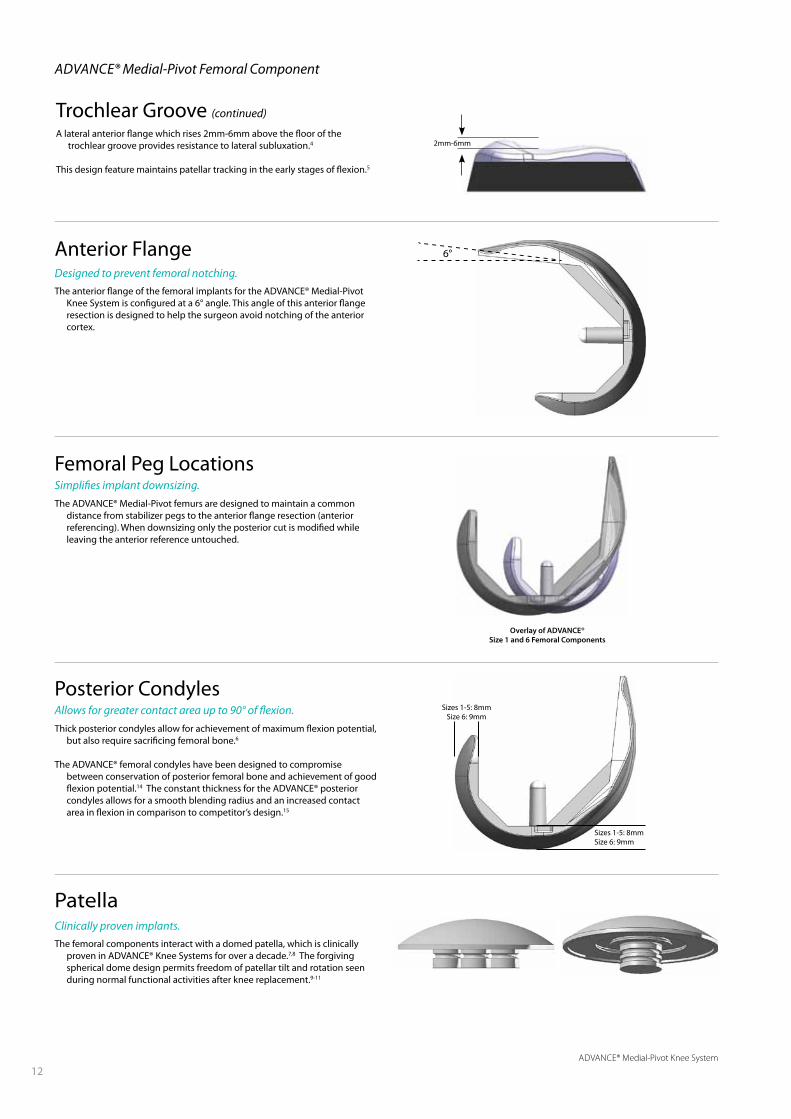
Trochlear Groove (continued)
A lateral anterior flange which rises 2mm-6mm above the floor of the trochlear groove provides resistance to lateral subluxation.4
This design feature maintains patellar tracking in the early stages of flexion.5
2mm-6mm
Femoral Peg LocationsSimplifies implant downsizing.
The ADVANCE® Medial-Pivot femurs are designed to maintain a common distance from stabilizer pegs to the anterior flange resection (anterior referencing). When downsizing only the posterior cut is modified while leaving the anterior reference untouched.
Overlay of ADVANCE®Size 1 and 6 Femoral Components
Clinically proven implants.
The femoral components interact with a domed patella, which is clinically proven in ADVANCE® Knee Systems for over a decade.7,8 The forgiving spherical dome design permits freedom of patellar tilt and rotation seen during normal functional activities after knee replacement.9-11
Patella
6°Anterior FlangeDesigned to prevent femoral notching..
The anterior flange of the femoral implants for the ADVANCE® Medial-Pivot Knee System is configured at a 6° angle. This angle of this anterior flange resection is designed to help the surgeon avoid notching of the anterior cortex.
ADVANCE® Medial-Pivot Femoral Component
Posterior CondylesAllows for greater contact area up to 90° of flexion.
Thick posterior condyles allow for achievement of maximum flexion potential, but also require sacrificing femoral bone.6
The ADVANCE® femoral condyles have been designed to compromise between conservation of posterior femoral bone and achievement of good flexion potential.14 The constant thickness for the ADVANCE® posterior condyles allows for a smooth blending radius and an increased contact area in flexion in comparison to competitor’s design.15
Sizes 1-5: 8mmSize 6: 9mm
Sizes 1-5: 8mmSize 6: 9mm
ADVANCE® Medial-Pivot Knee System
13
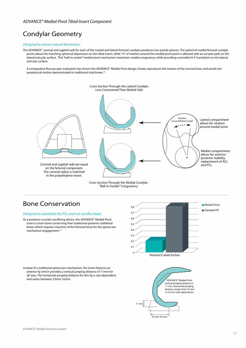
Designed to restore natural kinematics.
The ADVANCE® coronal and sagittal radii for each of the medial and lateral femoral condyles produces two partial spheres. The spherical medial femoral condyle pivots about the matching spherical depression on the tibial insert, while 15° of rotation around the medial-pivot point is allowed with an arcuate path on the lateral articular surface. This “ball-in-socket” medial-pivot mechanism maximizes medial congruency while providing controlled A-P translation on the lateral articular surface.
A comparative fluoroscopic evaluation has shown the ADVANCE® Medial-Pivot design closely reproduces the motion of the normal knee, and avoids the paradoxical motion demonstrated in traditional total knees.12
RotationAround Medial Condyle
Volume/Cubed Inches
0,8
0,7
0,6
0,5
0,4
0,3
0,2
0,1
0
Medial-Pivot
Standard PS
ADVANCE® Medial-Pivot Tibial Insert Component
Condylar Geometry
Bone ConservationDesigned to substitute the PCL and not sacrifice bone.
As a posterior cruciate sacrificing device, the ADVANCE® Medial-Pivot insert is more bone conserving than traditional posterior stabilized knees which requires resection of the femoral bone for the spine/cam mechanism engagement.13
Instead of a traditional spine/cam mechanism, the insert features an anterior lip which provides a vertical jumping distance of 11mm for all sizes. The horizontal jumping distance for this lip is size dependent, and varies between 23mm-32mm. ADVANCE® Medial-Pivot
vertical jumping distance is 11 mm. Horizontal jumping distance ranges from 23 mmto 32 mm (size dependent).
23 mm-32 mm
11 mm
Cross Section Through the Medial Condyle:“Ball-in-Socket” Congruency
Cross Section Through the Lateral Condyle:Less Constrained Than Medial Side
Coronal and sagittal radii are equalon the femoral component.
The coronal radius is matchedin the polyethylene insert.
Lateral compartment allows for rotation around medial pivot
Medial compartment allows for anterior-posterior stability, replacement of ACL and PCL

ADVANCE® Medial-Pivot Knee System
14
The orientation markings aid in properly aligning the tibial base. This is accomplished by aligning the center orientation marking with the medial one-third of the tibial tubercle.
The other markings allow versatility to help align the base for any exposure.
Dovetail Locking MechanismDovetail capture reduces micromotion.
The locking mechanism of the ADVANCE® Medial-Pivot Knee System relies on a dovetail capture and an interference fit to reduce micromotion.
Orientation MarkingsFacilitate rotational alignment.
Orientation markings have been incorporated into the anterior portion of the tibial base implant to allow the surgeon to identify rotational position of the tibial base implant during final impaction.
Tibial Sizing
Improved bone coverage and fit.Eleven tibial tray sizes are available within the ADVANCE® Medial-Pivot
Knee System. Within these sizes, six are known as “standard” and five as “plus” options, which configure a smaller locking mechanism on a larger tibial base profile. These have been generated to accommodate the interchangeability needs for the system.
For example, the tibial tray size 3+ features the same dimension of the tibial tray size 4 and the femoral component size 3 can be implanted with tibial tray size 3 or 3+, as shown in the Table.
FEMuR INSERT TIBIAL TRAY
1 1 1 or 1+
2 2 2 or 2+
3 3 3 or 3+
4 4 4 or 4+
5 5 5 or 5+
6 6 6
Applied load through femur
Peripheral dovetail
Peripheral dovetail
ADVANCE® Medial-Pivot Tibial Tray Component
ADVANCE® Medial-Pivot Knee System
15
50mm
Posterior
4mm
6mm
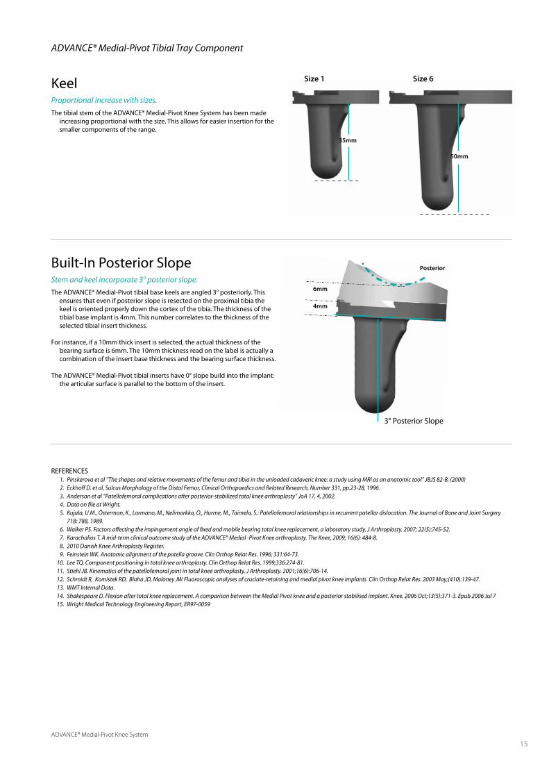
KeelProportional increase with sizes.
The tibial stem of the ADVANCE® Medial-Pivot Knee System has been made increasing proportional with the size. This allows for easier insertion for the smaller components of the range.
35mm
Size 1 Size 6
3° Posterior Slope
Built-In Posterior SlopeStem and keel incorporate 3° posterior slope.
The ADVANCE® Medial-Pivot tibial base keels are angled 3° posteriorly. This ensures that even if posterior slope is resected on the proximal tibia the keel is oriented properly down the cortex of the tibia. The thickness of the tibial base implant is 4mm. This number correlates to the thickness of the selected tibial insert thickness.
For instance, if a 10mm thick insert is selected, the actual thickness of the bearing surface is 6mm. The 10mm thickness read on the label is actually a combination of the insert base thickness and the bearing surface thickness.
The ADVANCE® Medial-Pivot tibial inserts have 0° slope build into the implant: the articular surface is parallel to the bottom of the insert.
ADVANCE® Medial-Pivot Tibial Tray Component
REFERENCES 1. Pinskerova et al “The shapes and relative movements of the femur and tibia in the unloaded cadaveric knee: a study using MRI as an anatomic tool” JBJS 82-B, (2000) 2. Eckhoff D. et al, Sulcus Morphology of the Distal Femur, Clinical Orthopaedics and Related Research, Number 331, pp.23-28, 1996. 3. Anderson et al “Patellofemoral complications after posterior-stabilized total knee arthroplasty” JoA 17, 4, 2002. 4. Data on file at Wright. 5. Kujala, U.M., Österman, K., Lormano, M., Nelimarkka, O., Hurme, M., Taimela, S.: Patellofemoral relationships in recurrent patellar dislocation. The Journal of Bone and Joint Surgery
71B: 788, 1989. 6. Walker PS. Factors affecting the impingement angle of fixed and mobile bearing total knee replacement, a laboratory study. J Arthroplasty. 2007; 22(5):745-52. 7. Karachalios T. A mid-term clinical outcome study of the ADVANCE® Medial -Pivot Knee arthroplasty. The Knee, 2009; 16(6): 484-8. 8. 2010 Danish Knee Arthroplasty Register. 9. Feinstein WK. Anatomic alignment of the patella groove. Clin Orthop Relat Res. 1996; 331:64-73. 10. Lee TQ. Component positioning in total knee arthroplasty. Clin Orthop Relat Res. 1999;336:274-81. 11. Stiehl JB. Kinematics of the patellofemoral joint in total knee arthroplasty. J Arthroplasty. 2001;16(6):706-14. 12. Schmidt R, Komistek RD, Blaha JD, Maloney JW Fluoroscopic analyses of cruciate-retaining and medial pivot knee implants Clin Orthop Relat Res. 2003 May;(410):139-47. 13. WMT Internal Data. 14. Shakespeare D. Flexion after total knee replacement. A comparison between the Medial Pivot knee and a posterior stabilised implant. Knee. 2006 Oct;13(5):371-3. Epub 2006 Jul 7 15. Wright Medical Technology Engineering Report, ER97-0059
ADVANCE® Medial-Pivot Knee System
16
The goal of any total knee implant system
is to provide the patient with a long-lasting solution that addresses their knee pain. However, patient expectations and satisfaction levels have steadily increased and patients require an option that most closely replicates the function of the normal knee. Multiple studies have characterized the movement of the normal knee, illustrating greater posterior translation of the lateral condyle over the medial condyle with increasing flexion.1,2 The normal knee has the ability to achieve higher ranges of active and passive flexion than conventional knee implants.3 As such, the need for a long-lasting knee system that can achieve normal knee kinematics, is stable throughout the range of motion, and incorporates features that assist in maximizing permissible flexion is desirable.
Conventional knee implants have been developed to rely either on soft tissue or a post and cam mechanism to predictably roll back, providing posterior translation of the femur on the tibia during flexion. However, many studies have illustrated that the rollback phenomenon does not occur with many conventional knee designs, especially those that incorporate a symmetric tibial insert. These implants illustrate “paradoxical motion,” where the femoral component translates anterior during early stages of flexion, instead of rolling back.3-8 This type of motion has been described by patients as feeling like “walking on ice”. It is also one of the main problems the medial-pivot “ball-in-socket” philosophy solves.9
In order to better understand the concept of the medial-pivot “ball-in-socket” philosophy, a brief reference to the anatomic structures that provide stability to the normal knee is necessary. The normal anatomy provides features that give the knee stability on the medial side and that allow a more mobile lateral compartment. The larger medial meniscus offers additional stability that the lateral meniscus does not. This is largely due to the medial meniscus being firmly attached to the proximal tibia and extensively attached to the capsule and larger medial collateral ligament. The lateral meniscus, which lacks the extensiveness of these attachments, is more mobile and may displace up to 1cm.10 The ligaments in the knee also serve as stabilizers for the knee joint. The anterior cruciate ligament (ACL) prevents posterior translation of the femur on the tibia, where the posterior cruciate ligament (PCL) is considered
ADVANCE® Medial-Pivot
Kinematics
16

ADVANCE® Medial-Pivot Knee System
17
In a primary knee arthroplasty, all of these structures are affected and most are dissected. In order to restore function of the normal knee, the function of the affected structures must be replicated. This is the fundamental mantra of the “ball-in-socket” philosophy. While all conventional TKA replacements attempt to alleviate pain, not all restore the function of the normal knee. The ADVANCE® Medial-Pivot Knee System aims to replicate the function of the normal knee by creating a “stable” medial compartment and permitting a mobile lateral compartment.
The “ball” portion of the “ball-in-socket” philosophy centers on the spherical condyles of the distal femoral component. The condyles of the ADVANCE® Medial-Pivot Knee System femoral implant have a spherical configuration to ensure the extension geometry is identical to the flexion geometry. FIguRE 2
This medial meniscal “socket” is what provides the ADVANCE® Medial-Pivot Knee System its stability. There are however other features that contribute to the high conformity of this design. The medial anterior lip acts to replace the PCL and minimize anterior femoral sliding while the posterior lip replaces the ACL in an effort to stop posterior slide. FIguRE 3
the primary stabilizer of the knee. Being almost twice as strong as the ACL, the PCL prevents posterior translation of the tibia on the femur. Additionally, the medial collateral ligament (MCL), is significantly larger than the lateral collateral ligament (LCL) and remains taut throughout the range of motion. The LCL, in the normal knee, remains taut only in extension and relaxes as soon as flexion initiates.10 FIguRE 1
Figure 2 | ADVANCe® Medial-Pivot Knee System “ball” feature
Figure 1 | Anatomic structures of the normal knee
PCL stops anterior slide
Medial meniscus and concave surface provide stability
ACL stopsposterior slide
Lateral meniscusallows motion
Figure 3 | ADVANCe® Medial-Pivot Knee System “socket” features
Medial posterior lipreplaces ACL andstops posterior slide
Medial meniscal“socket” providesstability
Medial anterior lip replaces PCL and stops anterior slide
Lateral meniscalpath allows for 15°of motion
When coupled with the “socket” of the tibial insert implant, this “ball-in-socket” ensures medial compartment stability throughout the range of motion, just like the normal knee. The more open lateral compartment allows more motion on the lateral side, just like the normal knee.11
In vivo kinematics studies assessed clinically successful total knee arthroplasties comparing the ADVANCE® Medial-Pivot to traditional posterior cruciate retaining designs. The kinematics of the knee motion, analysed during the stance phase of gait, proved that the medial-pivot knee had a medial-pivot motion, just like the normal knee, while posterior cruciate retaining designs had paradoxical roll forward of the tibia on the femur. 11
While the general goal for knee replacement surgery is to relieve pain and restore function, patient expectations have increased. Long-term clinical history has illustrated that knee systems averaging maximum flexion between 110-115° were necessary.12 However, these systems are now deemed antiquated, as the latest research is beginning to yield the mechanisms behind maximizing potential flexion for knee implants. This literature did not stipulate that averaging 110-115° of flexion is necessary to maximize survivorship, but patient demand has been the key factor in driving “high-flexion” implant sales.
Many companies have attempted to create “high-flexion” knee implants by making the posterior condyles thicker. By doing so, this relieves the articular geometry in the posterior compartment to gain additional posterior condylar offset to allow deeper flexion. However, more recent clinical studies have assessed no significant differences in active flexion between a “high-flex” implant and its conventional alternative.13,14 Even conventional PS “high-flex” implants have similar clinical observations, citing maximum active flexion angles around 112° of flexion.15
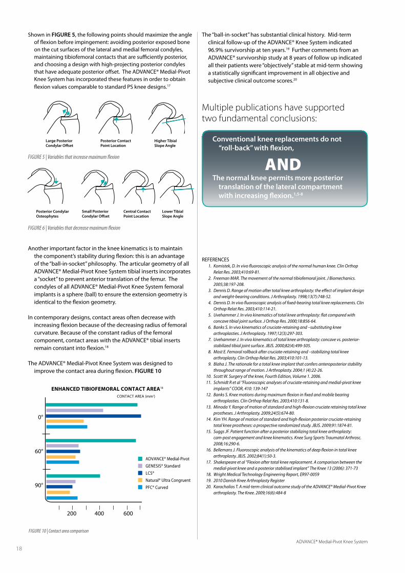
Several studies have provided information regarding factors which have a significant effect on maximum flexion.14-16 FIguRES 5 & 6
ADVANCE® Medial-Pivot Knee System
18
Posterior CondylarOsteophytes
Large PosteriorCondylar Offset
Small PosteriorCondylar Offset
Posterior ContactPoint Location
Central ContactPoint Location
Higher TibialSlope Angle
Lower TibialSlope Angle
Figure 5 | Variables that increase maximum flexion
Figure 6 | Variables that decrease maximum flexion
Shown in FIguRE 5, the following points should maximize the angle of flexion before impingement: avoiding posterior exposed bone on the cut surfaces of the lateral and medial femoral condyles, maintaining tibiofemoral contacts that are sufficiently posterior, and choosing a design with high-projecting posterior condyles that have adequate posterior offset. The ADVANCE® Medial-Pivot Knee System has incorporated these features in order to obtain flexion values comparable to standard PS knee designs.17
Another important factor in the knee kinematics is to maintain the component’s stability during flexion: this is an advantage of the “ball-in-socket” philosophy. The articular geometry of all ADVANCE® Medial-Pivot Knee System tibial inserts incorporates a “socket” to prevent anterior translation of the femur. The condyles of all ADVANCE® Medial-Pivot Knee System femoral implants is a sphere (ball) to ensure the extension geometry is identical to the flexion geometry.
In contemporary designs, contact areas often decrease with increasing flexion because of the decreasing radius of femoral curvature. Because of the constant radius of the femoral component, contact areas with the ADVANCE® tibial inserts remain constant into flexion.18
The ADVANCE® Medial-Pivot Knee System was designed to improve the contact area during flexion. FIguRE 10
Figure 10 | Contact area comparison
ADVANCE® Medial-Pivot
GENESIS® Standard
LCS®
Natural® Ultra Congruent
PFC® Curved
The “ball-in-socket” has substantial clinical history. Mid-term clinical follow-up of the ADVANCE® Knee System indicated 96.9% survivorship at ten years.19 Further comments from an ADVANCE® survivorship study at 8 years of follow up indicated all their patients were “objectively” stable at mid-term showing a statistically significant improvement in all objective and subjective clinical outcome scores.20
Conventional knee replacements do not “roll-back” with flexion,
ANDThe normal knee permits more posterior
translation of the lateral compartment with increasing flexion.1,5-8
Multiple publications have supported two fundamental conclusions:
ENhANCED tibiofEmorAl CoNtACt ArEA18
CONTACT AREA (mm2)
0°
60°
90°
200 400 600
REFERENCES 1. Komistek, D. In vivo fluoroscopic analysis of the normal human knee. Clin Orthop
Relat Res. 2003;410:69-81. 2. Freeman MAR. The movement of the normal tibiofemoral joint. J Biomechanics.
2005;38:197-208. 3. Dennis D. Range of motion after total knee arthroplasty: the effect of implant design
and weight-bearing conditions. J Arthroplasty. 1998;13(7):748-52. 4. Dennis D. In vivo fluoroscopic analysis of fixed-bearing total knee replacements. Clin
Orthop Relat Res. 2003;410:114-21. 5. Uvehammer J. In vivo kinematics of total knee arthroplasty: flat compared with
concave tibial joint surface. J Orthop Res. 2000;18:856-64. 6. Banks S. In vivo kinematics of cruciate-retaining and –substituting knee
arthroplasties. J Arthroplasty. 1997;12(3):297-303. 7. Uvehammer J. In vivo kinematics of total knee arthroplasty: concave vs. posterior-
stabilized tibial joint surface. JBJS. 2000;82(4):499-505. 8. Most E. Femoral rollback after cruciate-retaining and –stabilizing total knee
arthroplasty. Clin Orthop Relat Res. 2003;410:101-13. 9. Blaha J. The rationale for a total knee implant that confers anteroposterior stability
throughout range of motion. J Arthroplasty. 2004;1 (4):22-26. 10. Scott W. Surgery of the knee, Fourth Edition, Volume 1. 2006. 11. Schmidt R et al “Fluoroscopic analyses of cruciate-retaining and medial-pivot knee
implants” COOR, 410: 139-147 12. Banks S. Knee motions during maximum flexion in fixed and mobile bearing
arthroplasties. Clin Orthop Relat Res. 2003;410:131-8. 13. Minoda Y. Range of motion of standard and high-flexion cruciate retaining total knee
prostheses. J Arthroplasty. 2009;24(5):674-80. 14. Kim YH. Range of motion of standard and high-flexion posterior cruciate-retaining
total knee prostheses: a prospective randomized study. JBJS. 2009;91:1874-81. 15. Suggs JF. Patient function after a posterior stabilizing total knee arthroplasty:
cam-post engagement and knee kinematics. Knee Surg Sports Traumatol Arthrosc. 2008;16:290-6.
16. Bellemans J. Fluoroscopic analysis of the kinematics of deep flexion in total knee arthroplasty. JBJS. 2002;84(1):50-3.
17. Shakespeare et al “Flexion after total knee replacement. A comparison between the medial-pivot knee and a posterior stabilised implant” The Knee 13 (2006): 371-73
18. Wright Medical Technology Engineering Report, ER97-0059 19. 2010 Danish Knee Arthroplasty Register 20. Karachalios T. A mid-term clinical outcome study of the ADVANCE® Medial-Pivot Knee
arthroplasty. The Knee. 2009;16(6):484-8

ADVANCE® Medial-Pivot Knee System
19
Gender differentiated knee implant design is a new trend in orthopaedics. Several large companies have marketed their products based on the claim that men and women have different bony anatomy that requires specialized knee prostheses. Throughout the marketplace it is believed there are three main disparities between men and women relating to implant design: women have a greater trochlear groove angle, a narrower distal femur, and are more prone to anterior overstuffing.
There are several studies demonstrating an anatomic difference between men and women.1,2,3 However, few of these studies have taken into account the physical stature of individuals. Those studies that have examined other factors besides gender have found patient size is more of a determinant of implant size than gender.
Research has shown the Q-angle is not different due to gender, but is actually dependent on the height of the individual.5 If a man and a woman of equal height were measured, their Q-angles would be the same. Studies demonstrating a gender difference have not recognized men are on average taller than women. The studies simply separate the samples by gender; not stature. Other studies have shown there is no difference in the morphologies of the trochlear grooves of male and female fetuses. Furthermore, these morphologies do not change in adulthood.6,7
ADVANCE® Medial-Pivot
Stature™
The Science ofTotal Knee Sizing
ADVANCE® Medial-Pivot Knee System
20
52
56
60
64
68
72
76
80
84
40 45 50 55 60 65 70 75 80Femoral A/P
Fem
oral
M/L
ADVANCE - WrightADVANCE STATURE - WrightTriathlon - StrykerVanguard - BiometNexGen CR Flex - ZimmerNexGen CR GSK Flex - ZimmerPFC Sigma - DePuyJourney - Smith+Nephew
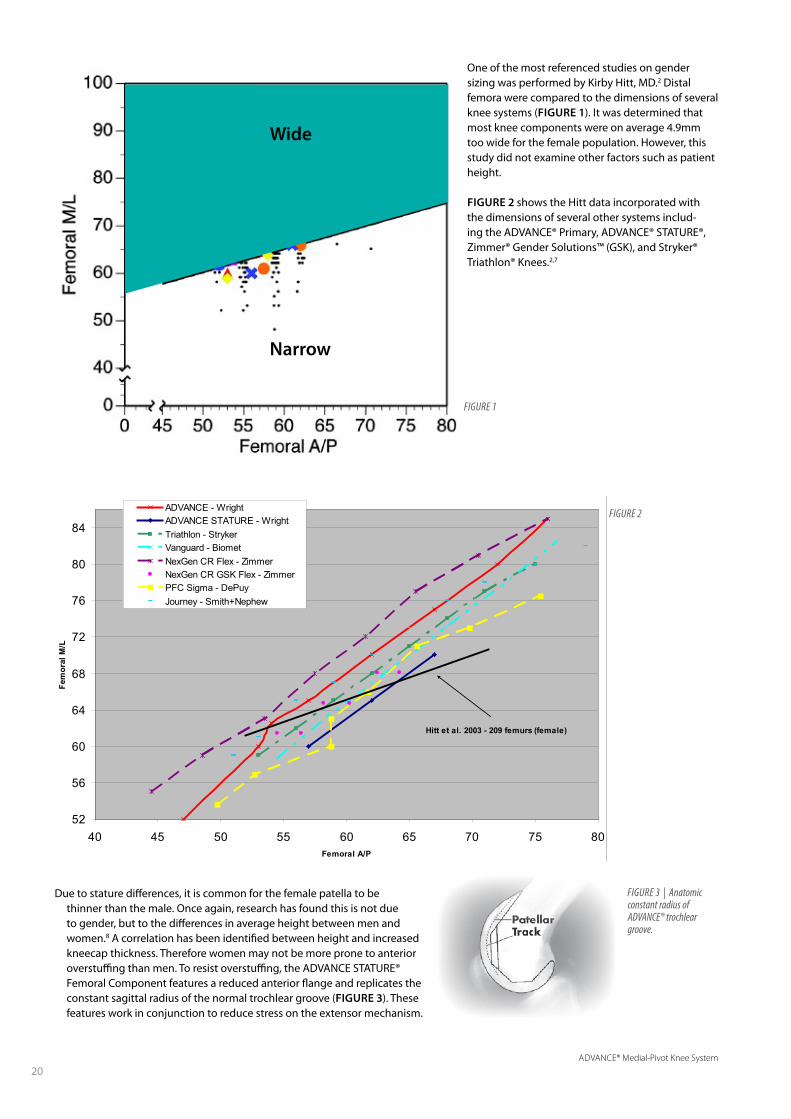
Hitt et al. 2003 - 209 femurs (female)
Due to stature differences, it is common for the female patella to be thinner than the male. Once again, research has found this is not due to gender, but to the differences in average height between men and women.8 A correlation has been identified between height and increased kneecap thickness. Therefore women may not be more prone to anterior overstuffing than men. To resist overstuffing, the ADVANCE STATURE® Femoral Component features a reduced anterior flange and replicates the constant sagittal radius of the normal trochlear groove (FIguRE 3). These features work in conjunction to reduce stress on the extensor mechanism.
Wide
Narrow
Figure 2
One of the most referenced studies on gender sizing was performed by Kirby Hitt, MD.2 Distal femora were compared to the dimensions of several knee systems (FIguRE 1). It was determined that most knee components were on average 4.9mm too wide for the female population. However, this study did not examine other factors such as patient height.
FIguRE 2 shows the Hitt data incorporated with the dimensions of several other systems includ-ing the ADVANCE® Primary, ADVANCE® STATURE®, Zimmer® Gender Solutions™ (GSK), and Stryker® Triathlon® Knees.2,7
Figure 3 | Anatomic constant radius of ADVANCe® trochlear groove.
ADVANCE® Medial-Pivot Knee System
21
REFERENCES 1. Poilvache PL, Insall JN, Scuderi GR, Font-Rodriguez DE. Rotational landmarks and
sizing of the distal femur in total knee arthroplasty. Clin Orthop Relat Res. 1996 Oct;(331):35-46.
2. K Hitt, et al. Anthropometric Measurements of the Human Knee: Correlation to the Sizing of Current Knee Arthroplasty Systems. JBJS 85:115-122 (2003).
3. Chin KR, Dalury DF, Zurakowski D, Scott RD. Intraoperative measurements of male and female distal femurs during primary total knee arthroplasty. J Knee Surg. 2002 Fall;15(4):213-7.
4. Grelsamer et al. Men and women have similar Q angles: a clinical and trigonometric evaluation. J Bone Joint Surg Br.2005; 87-B: 1498-1501.
5. Garron E, et al. Anatomic study of the anterior patellar groove in the fetal period Rev Chir Orthop Reparatrice Appar Mot. 2003 Sep;89(5):407-12.
6. Glard et al. An anatomical and biometrical study of the femoral trochlear groove in the human fetus. 2005. J Anat. Apr;206(4):411-3.
7. Goldstein W, et al. Implant Sizing and Female Gender in Total Knee Arthroplasty: Differences between US Manufacturers. AAHKS. November 2006, Poster #463.
8. Sulaiman AS, Nordin S. Measurement of patellar thickness in relation to patellar resurfacing. Med J Malaysia. 2005 Jul;60 Suppl C:41-4.
9. Pritchett JW. Patient preferences in knee prostheses. J Bone and Joint Surgery (BR). 2004 Sept;(86-B): 979-982.
10. Eckhoff D, et al. Sulcus morphology of the distal femur. Clin Orthop Relat Res. 1996 Oct;(331):23-8.
11. 2010 Danish Knee Arthroplasty Register.
A
C
C
B
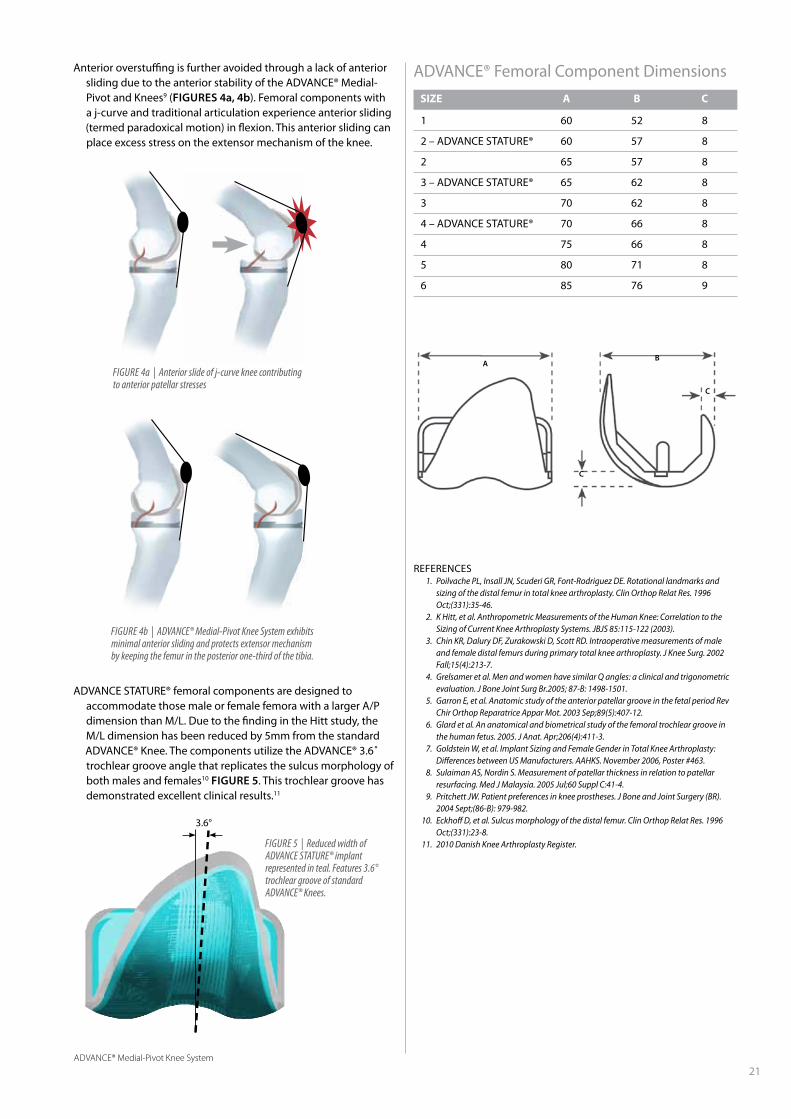
ADVANCE STATURE® femoral components are designed to accommodate those male or female femora with a larger A/P dimension than M/L. Due to the finding in the Hitt study, the M/L dimension has been reduced by 5mm from the standard ADVANCE® Knee. The components utilize the ADVANCE® 3.6˚ trochlear groove angle that replicates the sulcus morphology of both males and females10 FIguRE 5. This trochlear groove has demonstrated excellent clinical results.11
ADVANCE® Femoral Component Dimensions
SiZE A b C
1 60 52 8
2 – ADVANCE STATURE® 60 57 8
2 65 57 8
3 – ADVANCE STATURE® 65 62 8
3 70 62 8
4 – ADVANCE STATURE® 70 66 8
4 75 66 8
5 80 71 8
6 85 76 9
Figure 5 | reduced width of ADVANCe STATure® implant represented in teal. Features 3.6° trochlear groove of standard ADVANCe® Knees.
3.6°
Anterior overstuffing is further avoided through a lack of anterior sliding due to the anterior stability of the ADVANCE® Medial-Pivot and Knees9 (FIguRES 4a, 4b). Femoral components with a j-curve and traditional articulation experience anterior sliding (termed paradoxical motion) in flexion. This anterior sliding can place excess stress on the extensor mechanism of the knee.
Figure 4a | Anterior slide of j-curve knee contributing to anterior patellar stresses
Figure 4b | ADVANCe® Medial-Pivot Knee System exhibits minimal anterior sliding and protects extensor mechanism by keeping the femur in the posterior one-third of the tibia.

ADVANCE® Medial-Pivot Knee System
22
Multiple studies have cited
the most common mode for total knee arthroplasty failures
is instability.1-3 Many of these authors have stated that
attention must be paid to component alignment,
ligamentous balancing, and gap equalization as a means
to alleviate this particular failure mode.2 And while
these surgical management techniques are vital when
attempting to ensure a good outcome, implant design
must be considered and what contributions to instability, if
any, it may have.
Several in-vivo studies have illustrated “paradoxical motion”
(anterior translation of the femur on the tibial component
during flexion) in various functional activity assessments.
Some authors believe these outcomes may be improved
based on the implantation of a more conforming design.1-3
To help prevent this paradoxical motion, the ADVANCE®
Medial-Pivot Knee System has incorporated unique
features.
ADVANCE® Medial-Pivot
Stability
22ADVANCE® Medial-Pivot Knee System

ADVANCE® Medial-Pivot Knee System
23
Once this configuration enters any amount of flexion, the femoral component begins sliding forward (“paradoxical motion”).
FIguRE 4
The ADVANCE® Medial-Pivot Knee System has been designed to prevent this anterior sliding or “paradoxical motion.” The femoral extension geometry is identical to the flexion geometry on the medial compartment. FIguRE 5
REFERENCES 1. Fehring TK. Early failures in total knee arthroplasty. Clin Orthop Relat Res.
2001;392:315-8. 2. Sharkey PF. Why are total knee arthroplasties failing today? Clin Orthop Relat Res.
2002;404:7-13. 3. Callaghan JJ. Why knees fail, lessons learned. J Arthroplasty.2004;19(4):31-4. 4. 2010 Danish Knee Arthroplasty Register 5. Pritchett JW. Patients prefer a bicruciate-retaining or the medial-pivot total knee
prosthesis. J Arthroplasty. 2011;26(2):224-8.
Figure 3 | Medial section view of a conventional femoral implant at 0°
Figure 4 | Medial section view of a conventional femoral implant flexed at 30°
Figure 5 | Medial section of the ADVANCe® Medial-Pivot Cruciate-Substituting Knee flexed at 30°
The “ball-in-socket” philosophy is not a new concept to the industry and has been cited to have a 96.9% survivorship rate at ten years.4
The medial-pivot design philosophy has been utilized as a design to provide stability through the complete arc of knee flexion since 1994, and has been a fundamental component in the ADVANCE® Knee System design since 1998.
This “ball-in-socket” design provides consistent geometric features configured to prevent paradoxical motion.
Patients PREFER the “ball-in-socket” design over conventional CR (76%), Mobile-Bearing (61%) or PS (76%) TKA designs 5
Conventional knee implants have J-curved femoral components based on the four-bar link theory and no stabilizing structures to prohibit the femur from sliding forward. FIguRE 3

ADVANCE® Medial-Pivot Knee System
24
While instability is one of the leading causes of short-term failure
of knee implants, aseptic loosening and complications pertaining to polyethylene wear are still the leading causes of long-term failure for knee implants.1,2 Many companies have attempted to address this through the use of alternate materials, such as highly crosslinked polyethylene and/or the addition of vitamin E. While these technologies improve wear characteristics in total hip arthroplasty where bearings are loaded in crossing shear vectors, the value of highly crosslinked polyethylene in total knee arthroplasty is still unknown. Questions remain regarding the trade-off of this change in material as it relates to advanced wear characteristics vs. reduction of mechanical properties and increase in osteolytic potential.
In general, wear can be characterized as the loss of material in particulate form or deformation as a consequence of contact between two moving surfaces. 3-5 Researchers have identified four predominant wear processes in total joint replacement.3,5,6 FIguRE 1
ADVANCE® Medial-Pivot
Wear
ABRASIVE WEARThe shearing off of small peaks or undulations on the face of
the articulating surfaces that are in contact, resulting in the generation of small debris particles.
ADHESIVE WEAR The transfer of a softer material (polyethylene) to the surface of
a harder counter bearing material (CoCr), forming a transfer film that attaches to the metal and results in breakdown of the polyethylene.
Figure 1 | Common modes of wear in total knee arthroplasty
Abrasive WearThird-Body Wear
Adhesive Wear Fatigue Wear
ADVANCE® Medial-Pivot Knee System
25
non-crosslink
crosslink
non-crosslink
crosslink
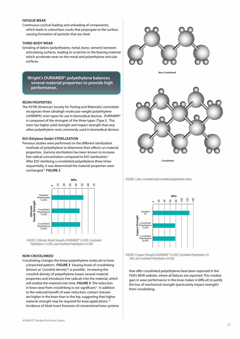
Non-Crosslinked
Figure 2 | ultimate Tensile Strength of DurAMer® (1x etO), Crosslinked Polyethylene (1x etO), and Crosslinked Polyethylene (3x etO)
Figure 4 | impact Strength of DurAMer® (1x etO), Crosslinked Polyethylene (1x etO), and Crosslinked Polyethylene (3x etO)
Figure 3 | Non-crosslinked and crosslinked polyethylene chains
RESIN PROPERTIESThe ASTM (American Society for Testing and Materials) committee
recognizes three ultrahigh-molecular-weight polyethylene (UHMWPE) resin types for use in biomedical devices. DURAMER® is composed of the strongest of the three types (Type I). This resin has higher yield strength and impact strength than any other polyethylene resin commonly used in biomedical devices.
EtO (Ethylene Oxide) STERILIzATIONPrevious studies were performed on the different sterilization
methods of polyethylene to determine their effects on material properties. Gamma sterilization has been known to increase free radical concentration compared to EtO sterilization.7 After EtO sterilizing a crosslinked polyethylene three times sequentially, it was determined the material properties were unchanged.8 FIguRE 2
that offer crosslinked polyethylene have been reported in the FDA’s MDR website, where all failures are reported. This modest gain in wear performance in the knee makes it difficult to justify the loss of mechanical strength (particularly impact strength) from crosslinking.
FATIguE WEARContinuous cyclical loading and unloading of components,
which leads to subsurface cracks that propogate to the surface, causing formation of particles that are shed.
THIRD-BODY WEARGrinding of debris (polyethylene, metal, bone, cement) between
articulating surfaces, leading to scratches in the bearing material which accelerate wear on the metal and polyethylene articular surfaces.
NON-CROSSLINKEDCrosslinking changes the linear polyethylene molecule to have
a branched pattern. FIguRE 3 Varying levels of crosslinking (known as “crosslink density”) is possible. Increasing the crosslink density of polyethylene lowers several material properties and introduces free radicals into the material, which will oxidize the material over time. FIguRE 4 The reduction in knee wear from crosslinking is not significant.9 In addition to the reduced benefit of wear reduction, contact stresses are higher in the knee than in the hip, suggesting that higher material strength may be required for knee applications.10 Incidence of tibial insert fractures of conventional knee systems
Wright’s DuRAMER® polyethylene balances several material properties to provide high performance.
StandardPolyethylene
1x EtO
CrosslinkedPolyethylene
1x EtO
CrosslinkedPolyethylene
3x EtO
0 10 20 30 40 50 60 70
MPa
Ulti
mat
eTe
nsile
Str
engt
h
StandardPE
CrosslinkedPolyethylene
1x EtO
CrosslinkedPolyethylene
3x EtO
0 20 40 60 80 100
120
140
MPa
Impa
ct S
tren
gth
Crosslinked

ADVANCE® Medial-Pivot Knee System
26
REFERENCES 1. Fehring TK. Early failures in total knee arthroplasty. Clin Orthop Relat Res.
2001;392:315-8. 2. Firestone TP. Surgical management of symptomatic instability following failed
primary total knee replacement. J Bone Joint Surg Am. 2006;88-A(4):80-4. 3. Jacobs JJ. Wear debris in total joint replacements. Journal of AAOS. 1994. 2(4):212-20.
July/August. 4. Wang J. Role of particulate debris in periprosthetic osteolysis. Techniques in
Orthopaedics. 1993. 8(4):245-53. 5. Lemons JE. The relationship between polyethylene quality and wear. Contemporary
Orthopaedics. 1995. 30(1):129-36. 6. Johnson WD. Polyethylene wear as a function of implant materials. Contemporary
Orthopaedics. 1995. 30(2):129-36. 7. Gomez-Barrena E. Update on UHMWPE Research: From the bench to the bedside. Acta
Orthop. 2008;79(6):832-40. 8. Data on file at Wright Medical. 9. McEwen HM. The influence of design, materials and kinematics on the in vitro wear of
total knee replacements. J Biomech. 2005;38:357-65. 10. Berry D. Factors influencing polyethylene wear. Orthopaedics. 1996;19(9):729-31. 11. Schwenke T. Difference in wear between load and displacement control tested total
knee replacements. Wear. 2009;267:757-62. 12. Haider H. Comparison between force-controlled and displacement-controlled in-vitro
wear testing on a widely used TKR implant. ORS poster. 2002;27:1007. 13. Muratoglu OK. Metrology to quantify wear and creep of polyethylene tibial knee
inserts. Clin Orthop Relat Res. 2003;410:155-64. 14. Fisher J. Wear, debris and biologic activity of crosslinked polyethylene in the knee. Clin
Orthop Relat Res. 2004;428:114-9. 15. Endo MM. Comparative wear and wear debris under three different counterface
conditions of crosslinked and non-crosslinked ultra high molecular weight polyethylene. Biomed Mater Eng. 2001; 11(1): 23-35.
16. Minoda Y. Polyethylene wear particles in synovial fluid after total knee arthroplasty. Clin Orthop Relat Res. 2003;410:165-72.
When compared to published data, the ADVANCE® Medial-Pivot Knee System has been shown to have a lower wear rate than DePuy’s LCS® and PFC® Sigma™ Rotating Platform and Zimmer’s Gender Solutions® NexGen® CR, M/G® II and Natural Knee® II Knee Systems9,11-13, suggesting that implant design may be more important than bearing materials. However, because these tests were conducted at other institutions not all testing variables can be accounted for, and small differences arising from the use of different machines, lubricants, measurement systems, and lab conditions cannot be evaluated and may have had an effect on the data comparison.
Just as important as volumetric wear rates, particle size and osteolytic potential play a role in the longevity of total joints. Both articular surface and backside wear have been identified as obvious sources of the generation of polyethylene debris particles regardless of material (crosslinked vs. non-crosslinked). Recent reports have focused on particle size and its bioreactive threshold with respect to crosslinked and non-crosslinked polyethylene. Crosslinked polyethylene showed an increase in biologic reactivity when compared to non-crosslinked polyethylene.14 This same study also pointed out that a smaller size of particles (< 0.1 µm) are generated from crosslinked polyethylene. Non-crosslinked polyethylene does generate wear particles, but has a greater concentration of the particles ranging from 0.1 µm to 1.0 µm. Wear particles ranging from 0.1 µm to 1.0 µm have a reduced bioreactive potential compared to smaller particles.15 Additional testing of the predicate “ball-in-socket” ADVANCE® Medial-Pivot system indicated the average particle size was 0.69 µm.16
ADVANCE®Medial-Pivot
Zimmer® Gender Solutions®NexGen® CR
Zimmer®M/G® II CR
Zimmer®Natural-Knee® II CR
DePuy LCS®Rotating Platform
DePuy PFC® Sigma™Rotating Platform
2520151050
7.1
5.2
4.0
15.6
9.8
8.3
Wear Rate (mm /Mc)3
ADVANCE® Medial-Pivot Knee System
27
REFERENCES 1. Niikura T. Patellar clunk syndrome after TKA with cruciate retaining design: a report of
two cases. Orthopedics 2008;31:90 2. Yong-Gon K. Arthroscopic treatment of patellofemoral soft tissue impingement after
posterior stabilized total knee arthroplasty. The Knee 2008;15:36-39 3. Ip D. Natural history and pathogenesis of the patella clunk syndrome. Arch Orthop
Trauma Surg 2004;124(9):597-602 4. Hozack WJ. The patellar clunk syndrome: a complication of posterior stabilized total
knee arthroplasty. Clin Orthop 1989;241:203-8 5. Beight JA, Yao B, Hozack WJ, et al. The patellar ‘clunk’ syndrome after posterior
stabilized total knee arthroplasty. Clin Orthop Relat Res 1994;299:139–142 6. Pritchett JW. Patients prefer a bicruciate-retaining or the medial-pivot total knee
prosthesis. J Arthroplasty. 2011;26(2):224-8. 7. Pritchett J. Patient preferences in knee prostheses. J Bone Joint Surg (Br)
2004;86(7):979-82 8. Anderson M. Patellofemoral complications after posterior-stabilized total knee
arthroplasty: a comparison of two different implant designs. J Arthroplasty 2002;17(4):422-6
Adapted from Pritchett6
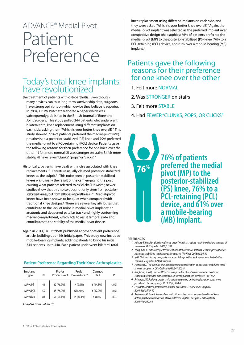
76% of patientspreferred the medialpivot (MP) to theposterior-stabilized(PS) knee, 76% to aPCL-retaining (PCL)device, and 61% overa mobile-bearing(MB) implant.
Patients gave the following reasons for their preference for one knee over the other
1. Felt more NORMAL
2. Was STRONGER on stairs
3. Felt more STABLE
4. Had FEWER “CLUNKS, POPS, OR CLICKS”
Today’s total knee implantshave revolutionizedthe treatment of patients with osteoarthritis. Even though
many devices can tout long-term survivorship data, surgeons have strong opinions on which device they believe is superior. In 2004, Dr. JW Pritchett authored a paper which was subsequently published in the British Journal of Bone and Joint Surgery. This study polled 344 patients who underwent bilateral total knee replacement using different implants on each side, asking them “Which is your better knee overall?” This study showed 77% of patients preferred the medial-pivot (MP) prosthesis to a posterior-stabilized (PS) knee and 79% preferred the medial-pivot to a PCL-retaining (PCL) device. Patients gave the following reasons for their preference for one knee over the other: 1) felt more normal; 2) was stronger on stairs; 3) felt more stable; 4) have fewer “clunks”, “pops” or “clicks.” 7
Historically, patients have dealt with noise associated with knee replacements.1-3 Literature usually claimed posterior-stabilized knees as the culprit.4 This noise seen in posterior-stabilized knees was usually the result of the cam engaging the post, causing what patients referred to as “clicks.” However, newer studies show that this noise does not only stem from posterior-stabilized knees, but from all types of prostheses.1,3,5 Medial-pivot knees have been shown to be quiet when compared with traditional knee designs.8 There are several key attributes that contribute to the lack of noise in medial-pivot implants: an anatomic and deepened patellar track and highly conforming medial compartment, which acts to resist femoral slide and contributes to the stabilty of the medial-pivot device.
Again in 2011, Dr. Pritchett published another patient preference article, building upon his initial paper. This study now included mobile-bearing implants, adding patients to bring his initial 344 patients up to 440. Each patient underwent bilateral total
ADVANCE® Medial-Pivot
PatientPreference
Patient Preference Regarding Their Knee Arthroplasties
ImplantType
MP vs PS 42 32 (76.2%) 4 (9.5%) 6 (14.3%) <.001
MP vs PCL 50 38 (76.0%) 6 (12.0%) 6 (12.0%) <.001
MP vs MB 83 51 (61.4%) 25 (30.1%) 7 (8.4%) .003
PreferProcedure 1
PreferProcedure 2
CannotTell PN
knee replacement using different implants on each side, and they were asked “Which is your better knee overall?” Again, the medial-pivot implant was selected as the preferred implant over competitive design philosophies: 76% of patients preferred the medial-pivot (MP) to the posterior-stabilized (PS) knee, 76% to a PCL-retaining (PCL) device, and 61% over a mobile-bearing (MB) implant.6
76%
1. Schmidt R et al “Fluoroscopic analyses of cruciate-retaining and medial-pivot knee implants” CORR, 410: 139-147
2. Poly wear particles in synovial fluid after TKA. Y. Minoda. C.O.R.R. #410 2003 3. 2010 Danish Knee Arthroplasty Register
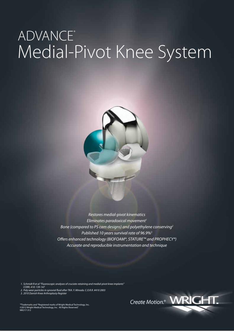
ADVANCE®
Medial-Pivot Knee System
Restores medial-pivot kinematics
Eliminates paradoxical movement1
Bone (compared to PS cam designs) and polyethylene conserving2
Published 10 years survival rate of 96.9%3
Offers enhanced technology (BIOFOAM®, STATURE™ and PROPHECY®)
Accurate and reproducible instrumentation and technique
™Trademarks and ®Registered marks of Wright Medical Technology, Inc.©2012 Wright Medical Technology, Inc. All Rights Reserved.”MK217-312