Embed Size (px)
Citation preview

Mechatronics tutorials By Atlas Huang, Jason Ho, Terry Brown
Background knowledge for Week 8
Required pre-tutorial work You should have watched the Lynda.com course Basic Electronics (at least sections 1-XX)
You should have watched the Lynda.com course Learning Arduino (at least sections 1-XX)
Schematics An important step to learning circuitry is to learn how to read schematics. Figure 1 is the schematic of an Arduino
board. It is for demonstration purpose only, it is not a requirement to fully understand the schematics. Figure 2 lists
a few electrical symbols that are frequently used in electronics projects. These electrical symbols help you to identify
the components in the schematics. The highlighted ones in Figure 2 are used in this subject and it is a requirement
to know how they are connected. You can test yourself by identifying all the LEDs in Figure 1. Do you notice that
there is a component that is always next to a LED?
Figure 1 Schematics of Sparkfun RedBoard
*Figure 1: https://cdn.sparkfun.com/assets/8/a/3/9/0/51cdbe19ce395f160b000001.png
*Figure 2: https://cdn.sparkfun.com/assets/6/8/6/d/1/51cdc767ce395f7558000002.png
*More on schematics: https://learn.sparkfun.com/tutorials/how-to-read-a-schematic

Figure 2 Electrical Symbols
Here are a few tips for reading schematics:
Electrical wiring can be thought of as similar to water flowing through pipes. You can think of the battery as
a water pump, the wires as pipes, the electrical components as hydraulic appliances.
Most of electrical components have positive and negative terminals. You can think of electricity as ‘flowing
in’ in at the positive terminal and ‘flowing out’ at the negative terminal.
The negative terminal of a battery is also known as ‘ground’. There can be multiple power sources on the
same circuit. However, if you want all the components to ‘communicate’ with each other, you will need to
establish a common ground (it means connecting the negative terminals of all power source together).
You can always find more information online. Here is an example of how to read schematics
(https://learn.sparkfun.com/tutorials/how-to-read-a-schematic/all ) and an example of electrical symbols
(http://www.rapidtables.com/electric/electrical_symbols.htm )
Wiring Wiring is to connect electrical components together according to the schematics. It is common practice to start from
the power source and use electrical cables to connect each component one after another. The process is similar to
connecting a piping system. In this subject, we use breadboard and jumper cables for wiring (Refer to Figure 3).
Breadboard and jumper cables are often used for prototyping because they can be easily assembled and

disassembled. There are metal strips inside the breadboard that allow you to connect multiple jumper cable together
(refer to Figure 4). Breadboards should only be used for prototyping. Once circuit design has been finalised, printed
circuit boards (PCB) should be produced and used.
Figure 3 Breadboard and Jumper Cable
Figure 4 Inside Breadboard
Connecting the positive and negative terminals of a power source together, without any electrical component in
between is called a short circuit. Short-circuits can damage every component on the same circuit, and it may cause
electric shock and fire. Most metals are good electrical conductors. Therefore, you should avoid working on a metal
surface, such as workbenches.
Resistors If you look at Figure 1 above carefully, you will notice that there is always a resistor in front of each LED. The resistor
is used to reduce electrical current passing through the LED and to ultimately avoid damaging the LED. Use Ohm’s
Law, V (voltage, volts) = I (current, amps) x R (resistance, ohms) to determine required resistor. There are online
calculators that help you to calculate the most suitable resistor size for your project.

Figure 5 Resistor Example
Resistors are usually colour coded to help users to identify the resistor value. Here are the steps to read the colour
code:
1. Identify the band that is slightly farther away from the others (such as the brown band in Figure 5)
2. Position the band identified in Step 1 to the right-hand side
3. Read the colour bands from left to the right and ignore the last one on the right
4. Each band represents one digit (for example, the resistor in Figure 1 has a value in 4 digits)
5. Different colour represents different value:
Figure 6 Resistor Colour Code
The resistor value in Figure 5 is 339Ω with +/-1% tolerance.
LEDs LEDs (Light emitting diodes) do not work when they are connected incorrectly. Electrical current goes into the LED at
the anode (possitive terminal) and come out at the cathode (negative terminal). Figure 7 shows a few tips on how to
identify the anode and cathode.

Figure 7 How to identify anode and cathode of an LED
*Figure 3: https://cdn.sparkfun.com//assets/parts/8/5/0/3/12002-01.jpg
https://cdn.sparkfun.com//assets/parts/3/7/0/4/11026-03.jpg
*Figure 4: https://cdn.sparkfun.com/assets/3/d/f/a/9/518c0b34ce395fea62000002.jpg
*More on breadboard: https://learn.sparkfun.com/tutorials/how-to-use-a-breadboard
*Figure 5: https://cdn.instructables.com/FIJ/YQGE/H4AGJN0C/FIJYQGEH4AGJN0C.MEDIUM.jpg
*Figure 6: http://www.digikey.com/-/media/Images/Marketing/Resources/Calculators/resistor-color-
chart.jpg?la=en-US&ts=72364a89-2139-476a-8a54-8d78dacd29ff
*More on resistor: http://www.digikey.com/en/resources/conversion-calculators/conversion-calculator-resistor-
color-code-5-band
*Figure 7: http://www.blocksignalling.co.uk/images/ledwiring.jpg

Installing Arduino software and Drivers You can download and install the Arduino software from https://www.arduino.cc/en/Main/Software . When you
plug the Arduino in for the first time you will need to download and install the Arduino drivers (this should happen
automatically).
Figure 8 How to get power from Arduino Board
*Figure 8: https://cdn.sparkfun.com//assets/parts/1/1/7/2/2/13975-04.jpg
Below is the Arduino Interface. You must ensure you select Uno as your board and select the right serial port (Setting
is highlighted in red). The serial monitor button is highlighted in orange, you can use it to read data directly from the
Arduino board.

Tutorial Exercises – Week 8 The power source provided in this tutorial is through the Arduino board. We will only use the Arduino as a power
source this week. Next week we will use the microcontroller and code to control the circuits we create.
1. Simple LED Circuit Attempt to create the circuit shown below.
2. LED Challenge In this challenge, you are required to think about and modify the circuit in Exercise 1 and complete the following:
Calculate the current in the circuit (Firstly, assume LED resistance is negligible. Secondly, attempt to use
LED data: Typical Voltage at 20mA: yellow/green/red/orange 1.8-2.2V, blue 2.6-3.0V)
Connect a Yellow LED in series with the existing Green LED
Connect a Red LED in parallel with the existing Green LED
Discuss with your group the brightness differences and why
3. Potentiometer with LED Attempt to create the circuit shown below.
4. Potentiometer Challenge In this challenge, you are required to think about and modify the circuit in Exercise 3 and complete the following:
Do some research on how a potentiometer works
Think about how you can add a Red LED to the circuit so that when the Green LED gets brighter the Red
LED gets dimmer and vice versa
Discuss with your group and draw a schematic
Show your schematic to your tutor before you wire it up to avoid damaging any component

5. LED and Photo Interrupter Attempt to create the circuit shown below. Be careful. Have your circuit checked before connecting power.
Note: the above diagram is a mirror image of the actual photo interrupter configuration.
Photo Interrupter schematic
Photo Interrupter Datasheet: https://www.sparkfun.com/datasheets/Components/GP1A57HRJ00F.pdf
6. Photo Interrupter Challenge In this challenge, you are required to connect the circuit in Exercise 3 and complete the following:
Do some research on how a photo interrupter works
The tutor will have a 4 – pin photo interrupter the same as that supplied with the WPV kit. Borrow this,
read the schematic, and attempt to create a circuit that turns a LED on and off.
Discuss with your team and draw a schematic
Show your schematic to your tutor before you wire it up to avoid damaging any component.
Show your completed circuit to your tutor before connecting power to your circuit.

Exercise Solution
Simple LED Circuit
Potentiometer with LED

LED and Photo Interrupter
Background knowledge for Week 9 This tutorial aims to guide you to develop a fundamental understanding of coding logic and a basic understanding of
how to program Arduino boards. There are three parts to this lesson: programming flowcharts, programming code
and wiring electronic circuits.
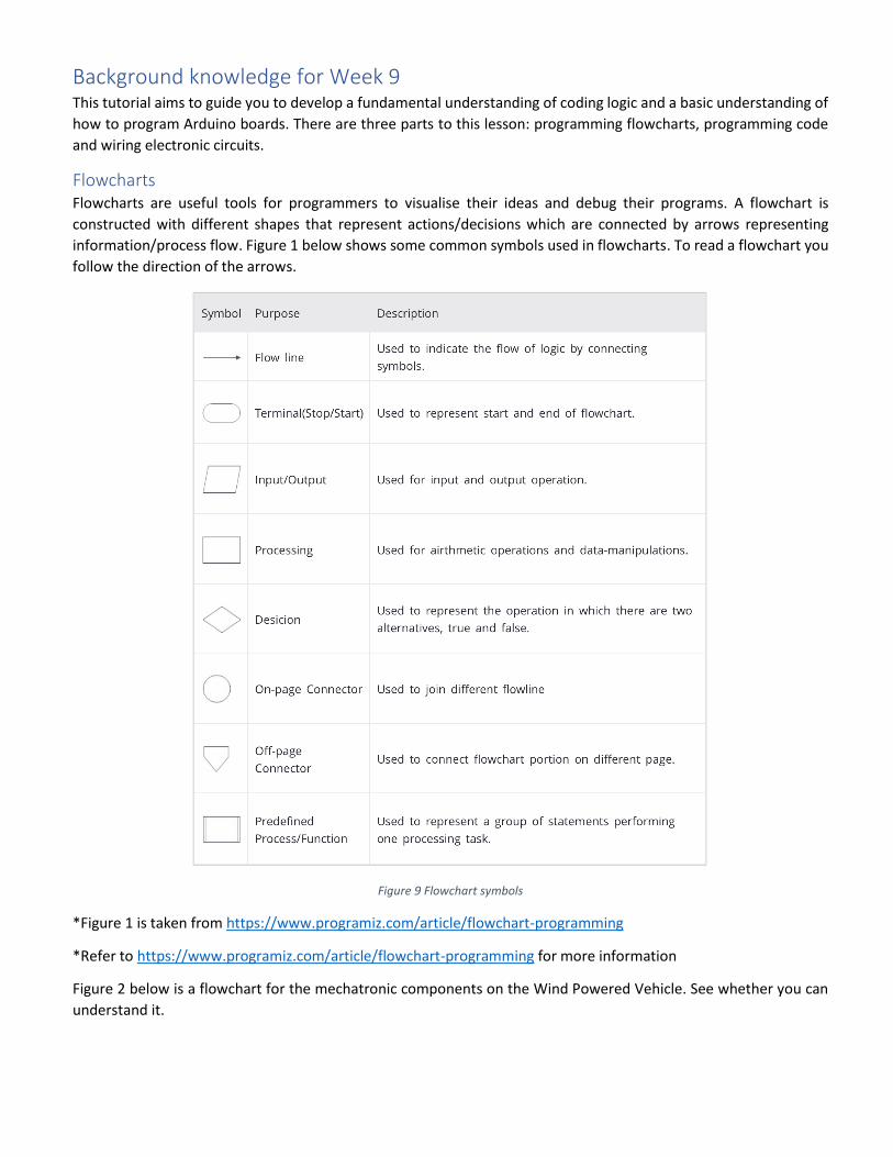
Flowcharts Flowcharts are useful tools for programmers to visualise their ideas and debug their programs. A flowchart is
constructed with different shapes that represent actions/decisions which are connected by arrows representing
information/process flow. Figure 1 below shows some common symbols used in flowcharts. To read a flowchart you
follow the direction of the arrows.
Figure 9 Flowchart symbols
*Figure 1 is taken from https://www.programiz.com/article/flowchart-programming
*Refer to https://www.programiz.com/article/flowchart-programming for more information
Figure 2 below is a flowchart for the mechatronic components on the Wind Powered Vehicle. See whether you can
understand it.

Figure 10 WPV Flowchart
Programming/coding This section aims to give you a basic understanding of coding with the Arduino programming language. You are
expected to read, understand and be able to modify existing code to suit your needs. The codes in tutorial materials
and WPV documents are commented with lots of explanations to assist your understanding. Your understanding will
be assessed in a mechatronic quiz, which is part of your WPV project.
An Arduino cheat sheet has been provided as learning material (refer to Figure 3 and also UTSOnline). Here you can
find the basic information you need to understand an Arduino program. The in-class activities will ask you to read
and modify example codes to perform a series of tasks.

Figure 11 Sparkfun Arduino Cheat Sheet
Tutorial Exercises – Week 9 The power source provided in this tutorial is through the Arduino board. We will also use the microcontroller and
code to control the circuits we create.
1. Blink In this exercise, you will need to:
Download, install and run the Arduino IDE software
Connect the Arduino board to your computer (via USB cable) and download drivers
Open Blink Example in the Arduino IDE
Upload the code to the Arduino board
You can find everything you need in this website https://learn.sparkfun.com/tutorials/installing-arduino-ide

2. Blink SOS In this exercise, you will need to:
Understand the Blink program you used in Exercise 1
Modify the code so the on-board LED blinks SOS (see Morse code table below)
Verify that the code is correctly written. This is called “compiling” the code. It only tells you if you have used
the language correctly. It doesn’t tell you if your code will do what you think it should/will do.
If all is well you should see something like the following:
If not, you will get an error message with an indication of where the compiler thinks the error is.
Note: SOS in Morse code is 3 times short, 3 times long and 3 times short (refer to the chart below)
*Taken from https://morsecode.scphillips.com/morse2.html
*In the table, “.” means short and “-“ means long

3. Add a Pushbutton to Blink In this exercise, you will need to:
Find the Button example under Examples/ 02.Digital/
Connect a 10K resistor and the push button to pin 2 (refer to the schematic below) and also
https://www.arduino.cc/en/tutorial/button . Have we wired a pull-up resistor or a pull-down resistor?
Upload the code
Test whether the code is working
Always connected across this way . Connected across this way as well when button is pressed.
4. Add a Pushbutton to BlinkSOS In this exercise, you will need to:
Understand the code used in Exercise 2 & 3
Adjust the code so that when the push button is pressed, the LED blinks SOS
Note: When the push button is pressed, the push button circuit is open and there is no voltage going into Pin 2. Think
about how you can use this property to activate blink sequence. Drawing a flowchart can be very useful here.
5. Simulate pedestrian crossing lights In this exercise, you will need to:
Add a red and a green LED to Pin 3 and 4 respectively (refer to schematic below)
Adjust the code you used in Exercise 4 so that the red LED is on until the push button is pressed, and the
green will then turn on for 5 seconds (it simulates a pedestrian traffic light)
See if you can make the red light blink before it turns back on

6. Use a Potentiometer to Generate an Analog Signal Attempt to create the circuit shown below.
Upload the code shown on the next page.
In this challenge, you are required to think about and complete the following:
Do some research on how to code LEDs and potentiometers in
Arduino
Use the serial monitor to see the output from the potentiometer
You will need to change the baud rate to match the rate set in the code

Think about how you can add a Yellow LED and a Red LED to the circuit so that each LED lights up
according to the A1 reading value
Tips: you can connect each LED to a digital pin and adjust the code
Discuss with your team, draw a schematic and adjust the code
Show your schematic and code to your tutor before you wire it up to avoid damaging any component
Upload the code below to read data:
/* Potentiometer Analog Sensor UTS 48610 - Introduction to Mechanical and Mechatronic Engineering - Autumn 2017 Written By Jason Ho Any Questions? Google it before asking your tutor. Feeling confident? Try modifying or adding to this code to add special features for your WPV i.e Flashing lights or even a data transmitter. Additional Notes: Camelback notation: You will see words like "statusLightsAreGood" with a lowercase first letter. */ #define Serial_Update_Interval 500 #define Analog_Pin A1 unsigned long oldMillis; // this stores the last value of millis when the Serial monitor printed the value of A1 void setup() Serial.begin(57600);// this connects the serial paort pinMode(Analog_Pin, INPUT);// this sets the pins mode to an input Serial.println("-----------------------------"); Serial.println("UTS IMME Analog Pot Reader"); Serial.println("-----------------------------"); Serial.println(""); void loop() if (millis() - oldMillis >= Serial_Update_Interval) // this checks if the interval time has passed (to avoid spamming the monitor) Serial.print("Analog "); Serial.print("A1"); Serial.print(" Reading: "); Serial.println(analogRead(Analog_Pin)); oldMillis = millis();// this store the current time which will be used to check if the interval time has passed for the next iteration

7. Make an Arduino Timing Game
Attempt to create the circuit shown below.
Upload the code shown on the next page.

Upload the code below to read data:
/* IMME Arduino Timing Game V1 UTS 48610 - Introduction to Mechanical and Mechatronic Engineering - Autumn 2017 Written by Jason Ho Any Questions? Google it before asking your tutor. Additional Notes: Camelback notation: You will see words like "statusLightsAreGood" with a lowercase first letter. This has been done to make it easier to read. */ #define photointerrupter 2 //Photo Interruptor Pin #define greenLED 3 //Green LED Pin #define redLED 4 //Red LED Pin #define targetCount 20 //Amount of times the photo interruptor needs to be tripped to finish the game #define FinishDelay 1000 //Delay (in ms) to prevent spamming //Variables (Global) int counter = 0; unsigned long timerStart; unsigned long finishTime; bool photoState = true; bool oldPhotoState = true; bool gameComplete = false; bool fail = false; void setup() pinMode(photointerrupter, INPUT); //Set Pin Types pinMode(greenLED, OUTPUT); pinMode(redLED, OUTPUT); digitalWrite(greenLED, HIGH); //Set Start Lights digitalWrite(redLED, HIGH); Serial.begin(9600); //Serial Monitor Interface - Start; Sends Text to Serial Monitor to explain game Serial.println(""); Serial.println("|-------------------------------|"); Serial.println("|UTS IMME Arduino Timing Game V1|"); Serial.println("|-------------------------------|"); Serial.println(""); Serial.print("Block photointerruptor "); Serial.print(targetCount); Serial.println(" time(s) as fast as possible. Go over and you lose."); Serial.println(""); Serial.println("Block photointerruptor to begin the game..........."); Serial.println("---------------------------------------------------"); //Serial Monitor Interface - End void loop() photoState = digitalRead(photointerrupter); // reads and sets the state of the photo interrupter if (photoState == HIGH && oldPhotoState != photoState) // the oldPhotoState != photoState ensures the counter is increase when there is a change in state if (counter == 0) // Start of game timerStart = millis(); // millis() is how long the arduino has been running in milliseconds; This statement saves the start time for future use digitalWrite(greenLED, LOW); digitalWrite(redLED, LOW);

Serial.println("Game Started!"); Serial.println(""); else if (counter == targetCount - 1) // targetCount- 1 is used because arduino is zero-indexed (counting starts at zero), meaning 0-20 is actualy 21 numbers finishTime = millis(); gameComplete = true; //Variable to flag that the games is complete else if (counter > targetCount - 1) fail = true; //Variable to flag that user has failed the game counter++; if (fail == true && gameComplete == true) digitalWrite(redLED, HIGH);// Set Red LED On Serial.println("You are not ready."); Serial.println(""); Serial.println("Reset the arduino to start again."); Serial.println("-------------------------------------"); while (true) // Stops Code from running until reset else if (gameComplete == true && fail == false && millis() - finishTime >= FinishDelay) //Checks if the game has finished and waits for 1 sec. this routine also gets blocked if the user made too many hits during the delay period or game period digitalWrite(greenLED, HIGH); // Set Green LED On Serial.print("Your finish time is "); Serial.print(float((finishTime - timerStart) / 1000.0)); //Converts Milliseconds to Seconds w/ Decimals Serial.println(" second(s)\r\n"); Serial.println("Reset the arduino to start again."); Serial.println("-------------------------------------"); while (true) // Stops Code from running until reset oldPhotoState = photoState; // Tracks changes of photo interruptor states between loop cycles
8. Timing game Coding Challenge In this challenge, you are required to think about and discuss the circuit in Exercise 7 and complete the following:
Do some research on how to code LED in Arduino
Try to understand the code and think about how the counter works
Discuss with your team on how to install an LED to cheat the game.
Discuss with your team, draw a schematic and adjust the code
Show your schematic and code to your tutor before you wire it up to avoid damaging any component
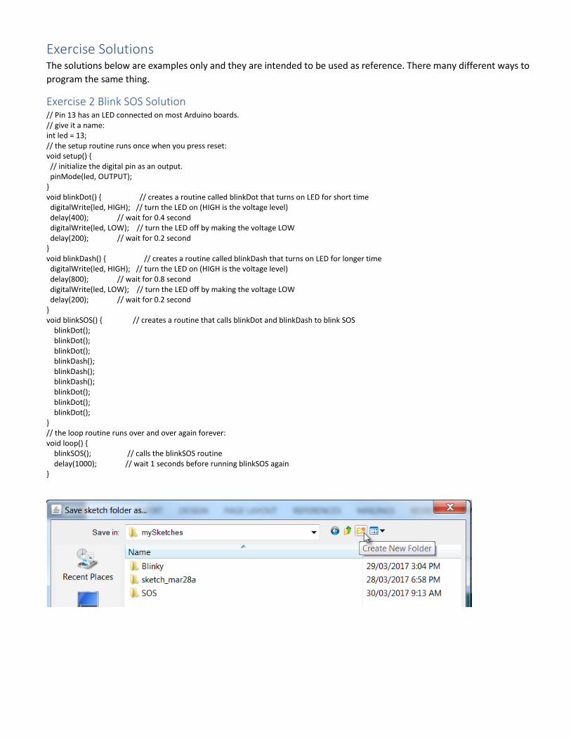
Exercise Solutions The solutions below are examples only and they are intended to be used as reference. There many different ways to
program the same thing.
Exercise 2 Blink SOS Solution // Pin 13 has an LED connected on most Arduino boards. // give it a name: int led = 13; // the setup routine runs once when you press reset: void setup() // initialize the digital pin as an output. pinMode(led, OUTPUT); void blinkDot() // creates a routine called blinkDot that turns on LED for short time digitalWrite(led, HIGH); // turn the LED on (HIGH is the voltage level) delay(400); // wait for 0.4 second digitalWrite(led, LOW); // turn the LED off by making the voltage LOW delay(200); // wait for 0.2 second void blinkDash() // creates a routine called blinkDash that turns on LED for longer time digitalWrite(led, HIGH); // turn the LED on (HIGH is the voltage level) delay(800); // wait for 0.8 second digitalWrite(led, LOW); // turn the LED off by making the voltage LOW delay(200); // wait for 0.2 second void blinkSOS() // creates a routine that calls blinkDot and blinkDash to blink SOS blinkDot(); blinkDot(); blinkDot(); blinkDash(); blinkDash(); blinkDash(); blinkDot(); blinkDot(); blinkDot(); // the loop routine runs over and over again forever: void loop() blinkSOS(); // calls the blinkSOS routine delay(1000); // wait 1 seconds before running blinkSOS again

Exercise 3 Add a Pushbutton to Blink Solution
Exercise 4 Add a Pushbutton to Blink SOS Solution // Pin 13 has an LED connected on most Arduino boards. // give it a name: int led = 13; int pb = 2; int pbState = 0; // the setup routine runs once when you press reset: void setup() // initialize the digital pin as an output. pinMode(led, OUTPUT); pinMode(pb, INPUT); void blinkDot() digitalWrite(led, HIGH); // turn the LED on (HIGH is the voltage level) delay(400); // wait for 0.4 second digitalWrite(led, LOW); // turn the LED off by making the voltage LOW delay(200); // wait for 0.2 second void blinkDash() digitalWrite(led, HIGH); // turn the LED on (HIGH is the voltage level) delay(800); // wait for 0.8 second digitalWrite(led, LOW); // turn the LED off by making the voltage LOW delay(200); // wait for 0.2 second void blinkSOS() blinkDot(); blinkDot(); blinkDot(); blinkDash(); blinkDash(); blinkDash(); blinkDot(); blinkDot(); blinkDot(); // the loop routine runs over and over again forever: void loop() pbState = digitalRead(pb);
if (pbState == LOW) blinkSOS(); else digitalWrite(led, LOW);
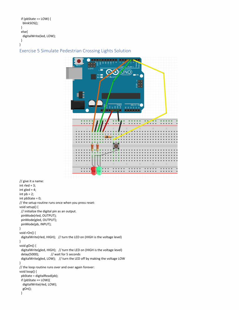
Exercise 5 Simulate Pedestrian Crossing Lights Solution
// give it a name: int rled = 3; int gled = 4; int pb = 2; int pbState = 0; // the setup routine runs once when you press reset: void setup() // initialize the digital pin as an output. pinMode(rled, OUTPUT); pinMode(gled, OUTPUT); pinMode(pb, INPUT); void rOn() digitalWrite(rled, HIGH); // turn the LED on (HIGH is the voltage level) void gOn() digitalWrite(gled, HIGH); // turn the LED on (HIGH is the voltage level) delay(5000); // wait for 5 seconds digitalWrite(gled, LOW); // turn the LED off by making the voltage LOW // the loop routine runs over and over again forever: void loop() pbState = digitalRead(pb); if (pbState == LOW) digitalWrite(rled, LOW); gOn();

else rOn();
Exercise 6 Use a Potentiometer to Generate Analog Signal Solution

Exercise 7 Make an Arduino Timing Game Solution