Embed Size (px)
Citation preview

MECHATRONIC SYSTEMS– INNOVATIVE PRODUCTS WITH EMBEDDED CONTROL –
Rolf Isermann
Institute of Automatic ControlDarmstadt University of Technology, Germany
Abstract: Many technical processes and products in the areaof mechanical and electricalengineering are showing an increasing integration of mechanics with digital electronicsand information processing. This integration is between the components (hardware)and the information-driven functions (software), resulting in integrated systems calledmechatronic systems. Their development involves finding anoptimal balance betweenthe basic mechanical structure, sensor and actuator implementation, automatic informa-tion processing and overall control. Of major importance are the simultaneous designof mechanics and electronics, hardware and software and embedded control functionsresulting in an integrated component or system. This technical progress has a very largeinfluence on a multitude of products in the area of mechanical, electrical and electronicengineering and changes the design, for example, of conventional electromechanicalcomponents, machines, vehicles and precision mechanical devices with increasing in-tensity. This contribution summarizes ongoing developments for mechatronic systems,shows design approaches and examples of mechatronic products and considers variousembedded control functions and system´s integrity. One field of ongoing developments,automotive mechatronics, is described in more detail by discussing mechatronic sus-pensions, mechatronic brakes, active steering and roll stabilization systems.Copyrightc©IFAC 2005
Keywords: mechatronics, component integration, embeddedcontrol, actuators,machines, automobiles, diagnosis, fault-tolerance, hardware-in-the-loop simulation,mechatronic suspensions, mechatronic brakes, active steering, roll-stabilization.
1. INTRODUCTION
Integrated mechanical electronic systems emerge froma suitable combination of mechanics, electronics andcontrol/information processing. Thereby, these fieldsinfluence each other mutually. First, a shift of func-tions from mechanics to electronics is observed, fol-lowed by the addition of extended and new functions.Finally, systems are being developed with certain in-telligent or autonomous functions. For these integratedmechanical electronic systems, the term “mechatron-ics” has been used for several years.
1.1 From mechanical to mechatronic systems
Mechanical systems generate certain motions or trans-fer forces or torques. For an oriented command of,e.g., displacements, velocities or forces,feedforwardand feedback control systemshave been applied formany decades. The control systems operate eitherwithout auxiliary energy (e.g., fly ball governor), orwith electrical, hydraulic or pneumatic auxiliary en-ergy, to manipulate the commanded variables directlyor with a power amplifier. Figure 1 summarizes thisdevelopment, beginning with the purely mechanical

Pure mechanical systems
1920
1935
1955
1975
1985
<1900DC motor 1870AC motor 1889
steam engine 1860
circular pumps 1880combustion engine1880
mech. typewriter
dynamos 1870
tool machinespumps
el. typewriter
steam turbinesaircraft
electroniccontrolled
lifts
machine toolsindustrial robotsindustrial plants
disk drives
mobile robotsCIM
magnetic bearingsautomotive control
(ABS, ESP)
Relays, solenoidshydraulic, pneumatic,electric amplifiersPI-controllers 1930
transistor 1948thyristor 1955
digital computer 1955process computer 1959
micro computer 1971digital decentralized automation 1975
real-time software 1966
micro controller 1978personal computers 1980process/field bus systemsnew actuators, sensorsintegration of components
Mechanical systems withelectrical drives
Mechanical systems withautomatic control
Mechanical systems withelectronic (analog) controlsequential control
l
l
Mechanical systems withdigital continuous controldigital sequential control
l
l
Mechatronic systemsl
l
l
l
integration: mechanics andelectronics hardwaresoftware determines functionsnew design tools forsimultaneous engineeringsynergetic effects
increasingelectricaldrives
increasingautomaticcontrol
increasingautomationwith processcomputersand miniaturi-sation
increasingintegrationof processesand micro-computers
Fig. 1. Historical development of mechanical, elec-tronic and mechatronic systems
systems of the nineteenth century to mechatronic sys-tems in the 1980s.
Figure 2 shows the forward oriented energy flow of amechanical energy converting systems (e.g., a motor)and the backward oriented information flow, which istypical for many mechatronic systems. Herewith, thedigital electronic system acts on the process based onmeasurements or external command variables.
If the electronic and the mechanical systems aremerged to an autonomous overall system, an inte-grated mechanical-electronic system results, calledmechatronic systemfrom conjoining MECHAnics andElecTRONICS. The word “mechatronics” was prob-ably first created by a Japanese engineer in 1969,(Kyura and Oho, 1996). Several definitions can befound in the literature, e.g., Mechatronics (1991),IEEE/ASME Transactions on Mechatronics (1996).The IFAC Technical Committee on Mechatronic Sys-tems, founded in 2000, (IFAC-T.C 4.2., 2000), usesthe following description: “Many technical processesand products in the area of mechanical and electricalengineering show an increasing integration of me-chanics with electronics and information processing.This integration is between the components (hard-ware) and the information-driven function (software),resulting in integrated systems calledmechatronicsystems. Their development involves finding an opti-mal balance between the basic mechanical structure,sensor and actuator implementation, automatic digitalinformation processing and overall control, and thissynergy results in innovative solutions.”
Hence, mechatronics is an interdisciplinary field, inwhich the following disciplines act together, Figure 3:
energy flow
information flowmanipulatedvariables
referencevariablesmonitored
variablesinformationprocessing
measuredvariables
actua-tors
sensors
energycon-
sumer
primaryenergyflow
mechanicalhydraulicthermal
electrical
consumerenergyflow
auxiliaryenergysupply
energysupply
mechanics andenergy converter
man/machineinterface
Fig. 2. Mechanical process and information process-ing develop towards a mechatronic system
microelectronicspower electronicssensorsactuators
electronicsinformationtechnology
mechanicsand
electro-mechanics
system theorymodelingautomation-technologysoftwareartificial intelligence
mechanical elementsmachinesprecision mechanicselectrical elements
MECHATRONICS
Fig. 3. Mechatronics: synergetic integration of differ-ent disciplines
(1) mechanical systems(mechanical elements, ma-chines, precision mechanics);
(2) electronic systems(microelectronics, power elec-tronics, sensor and actuator technology);
(3) information technology(systems theory, controland automation, software engineering, artificialintelligence).
The solution of tasks for designing mechatronic sys-tems is performed as well on the mechanical as on thedigital-electronic side. Herewith, interrelations duringthe designplay an important role; because the me-chanical system influences the electronic system andvice versa, the electronic system has influence on thedesign of the mechanical system. This means thatsimultaneous engineeringhas to take place, with thegoal of designing an overall integrated system (“or-ganic system”) and also creating synergetic effects.
A further feature of mechatronic systems is theinte-grated digital information processing. Except for ba-sic control functions, more sophisticated control func-tions may be realized, e.g., the calculation of non-measurable variables, the adaptation of controller pa-rameters, the detection and diagnosis of faults and,in the case of failures, a reconfiguration to redundantcomponents. Hence, mechatronic systems are evolv-
- anti-lock brakingsystem (ABS)
- electro-hydraulicbrake (EHB)
- activesuspension
- active frontsteering
Mechatronicsystems
Mechatronicmachine
components
Mechatronictrains
Mechatronicautomobiles
Mechatronicpower
consumingmachines
Mechatronicpower
producingmachines
- tilting trains- active boogie- magneticlevitated
(MAGLEV)trains
Mechatronicmotion
generators
- integratedmulti-axismachine tools
- integratedhydraulicpumps
- brushless DCmotor
- integrated ACdrives
- mechatroniccombustionengines
- integratedelectricalservo drives
- integratedhydraulicservo drives
- integratedpneumaticservo drives
- robots(multi-axis,mobile)
- semi-activehydraulicdampers
- magneticbearings
- automaticgears
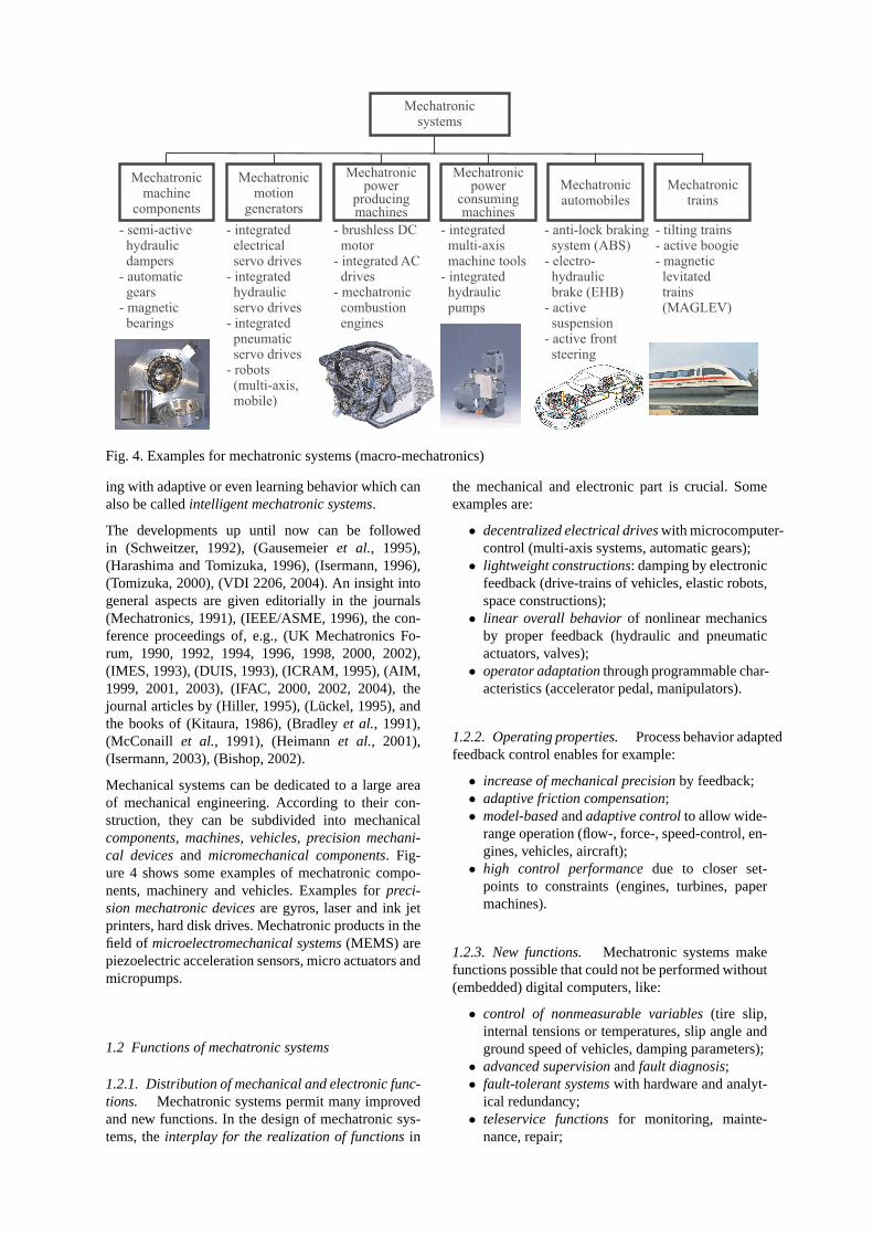
Fig. 4. Examples for mechatronic systems (macro-mechatronics)
ing with adaptive or even learning behavior which canalso be calledintelligent mechatronic systems.
The developments up until now can be followedin (Schweitzer, 1992), (Gausemeieret al., 1995),(Harashima and Tomizuka, 1996), (Isermann, 1996),(Tomizuka, 2000), (VDI 2206, 2004). An insight intogeneral aspects are given editorially in the journals(Mechatronics, 1991), (IEEE/ASME, 1996), the con-ference proceedings of, e.g., (UK Mechatronics Fo-rum, 1990, 1992, 1994, 1996, 1998, 2000, 2002),(IMES, 1993), (DUIS, 1993), (ICRAM, 1995), (AIM,1999, 2001, 2003), (IFAC, 2000, 2002, 2004), thejournal articles by (Hiller, 1995), (Lückel, 1995), andthe books of (Kitaura, 1986), (Bradleyet al., 1991),(McConaill et al., 1991), (Heimannet al., 2001),(Isermann, 2003), (Bishop, 2002).
Mechanical systems can be dedicated to a large areaof mechanical engineering. According to their con-struction, they can be subdivided into mechanicalcomponents, machines, vehicles, precision mechani-cal devicesand micromechanical components. Fig-ure 4 shows some examples of mechatronic compo-nents, machinery and vehicles. Examples forpreci-sion mechatronic devicesare gyros, laser and ink jetprinters, hard disk drives. Mechatronic products in thefield of microelectromechanical systems(MEMS) arepiezoelectric acceleration sensors, micro actuators andmicropumps.
1.2 Functions of mechatronic systems
1.2.1. Distribution of mechanical and electronic func-tions. Mechatronic systems permit many improvedand new functions. In the design of mechatronic sys-tems, theinterplay for the realization of functionsin
the mechanical and electronic part is crucial. Someexamples are:
• decentralized electrical driveswith microcomputer-control (multi-axis systems, automatic gears);
• lightweight constructions: damping by electronicfeedback (drive-trains of vehicles, elastic robots,space constructions);
• linear overall behaviorof nonlinear mechanicsby proper feedback (hydraulic and pneumaticactuators, valves);
• operator adaptationthrough programmable char-acteristics (accelerator pedal, manipulators).
1.2.2. Operating properties. Process behavior adaptedfeedback control enables for example:
• increase of mechanical precisionby feedback;• adaptive friction compensation;• model-basedandadaptive controlto allow wide-
range operation (flow-, force-, speed-control, en-gines, vehicles, aircraft);
• high control performancedue to closer set-points to constraints (engines, turbines, papermachines).
1.2.3. New functions. Mechatronic systems makefunctions possible that could not be performed without(embedded) digital computers, like:
• control of nonmeasurable variables(tire slip,internal tensions or temperatures, slip angle andground speed of vehicles, damping parameters);
• advanced supervisionandfault diagnosis;• fault-tolerant systemswith hardware and analyt-
ical redundancy;• teleservice functionsfor monitoring, mainte-
nance, repair;

Integration by information processing
on-line information processing
feedforward,feedbackcontrol
supervisiondiagnosis
adaptationoptimization
knowledge base
informationgaining:-identification-state observer
design methods:-control-supervision-optimization
performancecriteria
mathematicalprocess models
actuator process sensors
Integration of components
micro-computer
Fig. 5. Integration of mechatronic systems: integrationof components (hardware integration); integra-tion by information processing (software integra-tion)
• flexible adaptationto changing boundary condi-tions;
• programmable functionsallow changes duringdesign, commissioning and after-sales, and shortertime-to-market.
1.3 Integration forms
With increasing improvements of the miniaturization,robustness and computing power of microelectroniccomponents, one can try to put more weight on theelectronic side and to design the mechanical part fromthe beginning with a view to amechatronic overallsystem. Then, more autonomous systems can be envis-aged, e.g., in the form of capsular units with wirelesssignal transfer or bus connections and robust micro-electronics. The integration within a mechatronic sys-tem can be performed mainly in two ways, through theintegration of components and through integration byinformation processing.
Theintegration of components(hardware integration)results from designing the mechatronic system as anoverall system and embedding the sensors, actuatorsand microcomputers into the mechanical process, seeFigure 5. This spatial integration may be limited to theprocess and sensor or the process and actuator. Themicrocomputers can be integrated with the actuator,the process or sensor, or be arranged at several places.Integrated sensors and microcomputers lead tosmartsensorsand integrated actuators and microcomputersdevelop intosmart actuators. For larger systems, busconnections will replace the many cables.
Integration by information processing(software inte-gration) is mostly based on advanced control func-tions. Besides a basic feedforward and feedback con-trol, an additional influence may take place throughthe process knowledge and corresponding on-line in-formation processing in higher levels, see Figure 5.This includes the solution of tasks like supervisionwith fault diagnosis, optimization and general processmanagement. The respective problem solutions re-sult in anon-line information processing, especiallyby real-time algorithms, which must be adapted tothe mechanical process properties, e.g., expressed bymathematical models. Therefore, aknowledge baseisrequired, comprising methods for design and informa-tion gain, process models and performance criteria. Inthis way, the mechanical parts are governed in vari-ous ways through higher level information processingwith intelligent properties, possibly including learn-ing, thus forming anintegration by process adaptedsoftware.
2. DESIGN PROCEDURE
The design of mechatronic systems requires a sys-tematic development and use of modern software de-sign tools. As with any design, mechatronic design isalso an iterative procedure. However, it is much moreinvolved than for pure mechanical or electrical sys-tems. In addition to the traditional domain specific en-gineering (mechanical, electrical/electronic, automa-tion, user interface) an integrated, simultaneous (con-current) engineering is required. It is theintegrationof engineering across traditional boundariesthat istypical for the development of mechatronic systems.
A representation of important design steps, which dis-tinguishes especially between themechatronic systemdesignand system integrationis depicted in Figure6. This scheme is represented in form of a “V”-model, which originates probably from software de-velopment, (STARTS GUIDE, 1989), (Bröhl, 1995),see also (VDI 2206, 2004).
Within this V-model-development scheme only someexamples for specific mechatronic issues are consid-ered here. Thesystem designincludes the task dis-tribution between mechanical, hydraulic, pneumatic,electrical and electronic components, the used aux-iliary power, the type and placement of sensors andactuators, the electronic architecture, the software ar-chitecture, the control engineering design and the cre-ation of synergies. Because of the many varieties ofdesigns the advancemodellingand simulationplaysan important role, also to save the number of realizedprototypes. Therefore, theoretical/physical modellingof the heterogeneous components is required, usinggeneral modelling principles. For this purpose object-oriented software tools like DYMOLA, MODELICA,MOBILE, VHDL-AMS, 20 SIM are especially suit-able, see (Otter and Cellier, 1996), (Elmqvist, 1993),

validation
degree of maturity
verification
system d
esign
- mechanics- electronics
Requirements- overall functions- rated values- costs & milestones
Specifications- fulfillment of requirements- sources, limitations- reliability, safety
Modeling & Simulation- models of components- behavior analysis- requirements for componentsdesign
System design- partitioning- modules- mechanics vs. electronics- synergies
Prototypes- laboratory solutions- modifications of former products- prototype computers/algorithms
Production- simultaneous planning- technologies- assembling- quality control
Field testing- final product- normal use- statistics- certification
System testing- test rigs- stress testing, EMC- behavior testing- reliability, safety
System integration (software)- signal analysis- filtering- tuning of algorithms
System integration (hardware)- assembling- mutual adaptation- optimization- synergies
Component testing / tuning- hardware-in-the-loop simulation- stress analysis
syst
em inte
grat
ion
mechanics electronics automaticcontrol
human-machineinterface
- control-software- human-machine interface
Mechatronic components
ECU
Bypass
Computer
ECU
Bypass
Computer
ECU
Bypass
Computer
Engine
Simulation
Engine
Simulation
Engine
Simulation
Component design (domain specific)
Fig. 6. “V” development scheme for mechatronic systems
(Hiller, 1995), (van Amerongen, 2004), together withsimulation tools like MATLAB/SIMULINK.
In this stage of development, use is made ofsoftware-in-the-loop simulation(SiL), i.e., components andcontrol algorithms are simulated on an arbitrary com-puter without real-time requirements to obtain, e.g.,design specifications, dynamic requirements and per-formance measures. Thecomponent designis domainspecific and uses general CASE-tools, like CAD/CAEfor mechanics, CFD-tools for fluidics, circuit boardlayout-tools (PADS), microelectronic design tools(VHDL) and CADCS-tools for automatic control de-sign. Also the reliability and safety is considered, seeSection 4. Then prototypes are build as laboratory so-lutions. The system integration begins with first stepsto combine the different components. Because of thedifferent development status of the components duringthe simultaneous design, minimization of iterative de-velopment cycles and meeting of short time-to-marketschedules, frequently use is made of different kind ofreal-time simulations, Figure 7 and (VDI 2206, 2004).
A first case is therapid control prototyping(RCP)where the real process is operated together withthe simulated controlby a high-speed hardware andsoftware other than the final electronic control unit(ECU) (either full-passing or partially by-passing theECU with special software functions on the RCP-computer). A second case is thehardware-in-the-loop simulation(HiL), where the real-time simulatedprocess runs with the real ECU hardware and alsoactuator hardware. This is an especially demanding
task, because the real-time process simulation must berather precise and the sensor outputs signals have tobe realized with special interface circuits. Advantagesof HiL are, e.g., testing in laboratory environment,testing under extreme operating conditions and withfaults, reproductive experiments, design of human-machine interface. Thesystem integrationcomprisesthe spatial integration of thehardware componentsbyembedding the sensors, actuators, cables and buseson or into the mechanics and creation of synergeticeffects and the functional integration by thesoftwarewith all algorithms from control through adaptationto supervision, fault diagnosis, fault tolerance and hu-man/machine operation.
3. AUTOMATIC CONTROL OF MECHATRONICSYSTEMS
3.1 Control design
The applied feedforward and feedback control al-gorithms depend on the individual properties of theelectrical, mechanical, hydraulic, pneumatic and alsothermal processes. They can be brought into a gen-eral knowledge-based multi-level control structure asshown in Figure 8. The knowledge base consists ofmathematical process models, identification and para-meter estimation algorithms, controller design meth-ods and control performance criteria. The feedbackcontrol can be organized into lower level and higherlevel controllers, a reference value generation module

SiL
T
p2
2
p2,stat
T2,stat
qFW
n eng
controlalgorithm
p2
p2, Setpoint
qFW
n eng
upwm
process model
simulation tool
real process (engine) real ECU + real actuator(injection pump)
high performancereal-time computer(full pass, bypass)
integratedmechatronic
system(final product)
ECU model
HiL
RCP
Fig. 7. Various kinds of combining real and simulated parts for development: SiL: Software-in-the-loop; RCP:rapid control prototyping; HiL: Hardware-in-the-loop
controllerdesign
parameterestimation
mathem.models
sensors
kn
ow
led
ge
bas
e
feed
bac
k c
on
tro
l le
vel
s
perfor-mancecriteria
processactuatorsmanualcontrol
u y,
u
w
w
controlleradaptation
referencegeneration
higher levelcontroller
lower levelcontroller
y
y
y22
11
Fig. 8. Knowledge-based multi-level feedback controlfor mechatronic systems
and controller parameter adaptation. Because of thelarge variety of possibilities, only some control princi-ples will be considered briefly. More methods are, forexample, presented in (Spong and Vidyasagar, 1989),(Morari and Zafirov, 1989), (Åström and Wittenmark,1997), (Isidori, 1999), (Dorf and Bishop, 2001) and(Goodwinet al., 2001).
Some basic design requirements are limited compu-tations because of real-time constraints, nonlinearityof the processes, limited actuator speed and range,robustness, transparency of solutions, maintainability,etc. Of major importance is thesimultaneous designofthe mechatronic processand thecontrol. This meansthat the static and dynamic behavior of the process, thetype and placement of the actuators, the type and posi-tion of the sensors are designed appropriately, result-ing in an “control dynamic friendly” overall behavior.(A very important item for any control design.)
The goal of thelower level feedbackis to provide acertain dynamic behavior (e.g., enforcement of damp-
ing), to compensate nonlinearities like friction, to re-duce parameter sensitivity and to stabilize. Some typ-ical examples are:
Damping of high-frequency oscillations: weakly dampedoscillations appear, e.g., in multi-mass drivetrains orpneumatic and hydraulic actuators. The damping cangenerally be improved by high-pass filtering the out-puts and using a state variable or PD (proportional-derivative) feedback.
Compensation of nonlinear static characteristics: non-linear static characteristics are present in many sub-systems of mechanical processes. Figure 9 shows atypical example, the often required position controlfor a nonlinear actuator. Frequently, a first nonlinearityappears in the force- or torque-generating part like anelectromagnet or a pneumatic or hydraulic actuatorwhere, e.g., the forceFD = f (U) follows a nonlin-ear static characteristic. This nonlinearity can now becompensated by an inverse characteristicU = f−1(U′)such that the I/O behaviorFD = f (U′) becomes ap-proximately linear and a linear (PID-type) controllerGc1 can be applied.
Friction compensation: for many mechanical systems,the overall friction can be described approximately by
FF±(t) = fFC± signY(t)+ fFv± Y(t) |Y(t)|> 0 (1)
wherefFC is the Coulomb friction andfFν the linearviscous friction coefficient which may be dependenton the motion direction, indicated by+ or −. TheCoulomb friction has a strong negative effect on thecontrol performance. Different methods such as com-pensating the relay function, see Figure 9, dithering,feedforward compensation and adaptive friction com-pensation are alternatives, see, e.g., (Isermann and

parameter estimation & controller design & supervision
positioncontrollerwithfrictioncompensation
casade control non-linear actuator
force controllerwith non-linearforce compen-sation
force generation
cM
Fc
FFUFC
FL
FD
m mGc2 Gc1
Q1QQ2Q
r
U Y Y
YY
.
.U
mechanical motion
1m
U
Fig. 9. Adaptive position control of a nonlinear electromechanical, hydraulic or pneumatic actuator (example)
Raab, 1993), (Tomizuka, 1995) and (Canudas de Witet al., 1995).
An alternative for position control of nonlinear actua-tors is the use of asliding mode controller. It consistsof a nominal part for feedback linearization and an ad-ditional feedback to compensate for model uncertain-ties, (Utkin, 1977), (Slotine and Weiping, 1991). Theresulting chattering by the included switching functionhereby generates a dither signal. A comparison with afixed PID-controller with friction compensation shows(Pfeuferet al., 1995).
Stabilization: unstable mechatronic systems like mag-netic bearings, magnetic levitated trains or skiddingautomobiles have to be stabilized in the lower controllevel by appropriate feedback laws. The stabilizationfeedback usually includes derivative terms and in thecase of magnetic actuators compensating terms for thenonlinearities.
Switching actuator control: low-cost actuators in theform of solenoids or pneumatic membrane-types areusually manipulated by pulse-width-modulated inputsignals of higher frequency allowing approximatelylinear behavior for control of their position or fluidpressure in the lower frequency band.
The control scheme of the lower level control maybe expanded by additional feedback controllers froma load or working process that is coupled with themechanical process, resulting in a multiple-cascadedcontrol system. A prerequisite for the application ofadvanced control algorithms is the use of well-adaptedprocess models. This may lead to self-tuning oradap-tive control systems.
The task of thehigher level controlleris to generate agood overall dynamic behavior with regard to changesof the position referencer(t) and to compensate forexternal disturbances stemming, e.g., from load varia-tions. This high-level controller may be realized as aparameter optimized controller of PID-type or internal
model controller or a state controller with or withoutstate observer.
Parameter scheduling: parameter (or gain) schedulingbased on the measurement of, e.g., load-dependentvariables is an effective method to deal with knownvarying process behavior.
Parameter-adaptive control systems: parameter-adaptivecontrol systems are characterized by using identifi-cation methods for parametric process models. Thisis indicated in the adaptation level of Figures 8 and9. Parameter estimation has proven to be an appro-priate basis for the adaptive control of mechanicalprocesses, including the adaptation to nonlinear char-acteristics, Coulomb friction, and the unknown para-meters like masses, stiffness, damping, see (Isermannand Raab, 1993), (Isermannet al., 1992), (Åström andWittenmark, 1997).
If no appropriate sensors to measure the controlledvariable are availablefeedforward controlhas to beused. Feedforward controls may be realized as simpleproportional or proportional-derivative algorithms, asstatic nonlinear characteristicsu= f (y) or as nonlinearlook-up tables/mapsu = f(y). The last case holds,e.g., for the control of internal combustion engineswhere low-cost sensors for torque and emissions arenot available and stability problems have to be avoidedunder all circumstances.
A considerable part of the automation of mechatronicsystems is performed bysequential control, e.g., forprocesses with repetitive operation (machine-tools,printing machines), start-up and shut-down (engines)or automatic gears. Hence, mechatronic systems makeuse of a large variety of different control methods,ranging from simple proportional or on-off controllersto internal model and adaptive nonlinear controllers.Because the process model structure is mostly known,structure optimized controllers can be realized. Theprocess model order is usually not large, but nonlin-
change detection
fault diagnosis
diagnosed faults
signal-basedfault detectionprocess
model-basedfault detection
normalbehavior
s analytical symptoms
f
limit-plausibility
check
vibrationsignal
models
process
processmodel
featuregeneration
faults
actuatorsU
N
Y
x featuresr ,Q ,
sensors
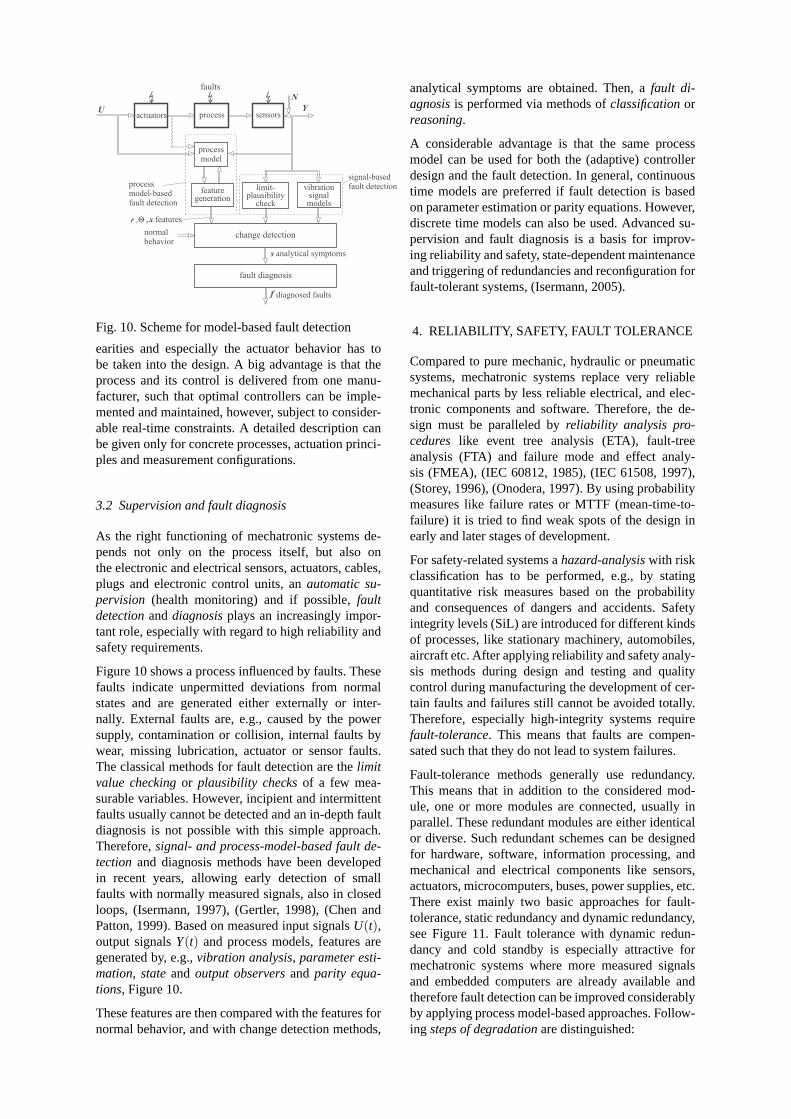
Fig. 10. Scheme for model-based fault detection
earities and especially the actuator behavior has tobe taken into the design. A big advantage is that theprocess and its control is delivered from one manu-facturer, such that optimal controllers can be imple-mented and maintained, however, subject to consider-able real-time constraints. A detailed description canbe given only for concrete processes, actuation princi-ples and measurement configurations.
3.2 Supervision and fault diagnosis
As the right functioning of mechatronic systems de-pends not only on the process itself, but also onthe electronic and electrical sensors, actuators, cables,plugs and electronic control units, anautomatic su-pervision (health monitoring) and if possible,faultdetectionanddiagnosisplays an increasingly impor-tant role, especially with regard to high reliability andsafety requirements.
Figure 10 shows a process influenced by faults. Thesefaults indicate unpermitted deviations from normalstates and are generated either externally or inter-nally. External faults are, e.g., caused by the powersupply, contamination or collision, internal faults bywear, missing lubrication, actuator or sensor faults.The classical methods for fault detection are thelimitvalue checkingor plausibility checksof a few mea-surable variables. However, incipient and intermittentfaults usually cannot be detected and an in-depth faultdiagnosis is not possible with this simple approach.Therefore,signal- and process-model-based fault de-tection and diagnosis methods have been developedin recent years, allowing early detection of smallfaults with normally measured signals, also in closedloops, (Isermann, 1997), (Gertler, 1998), (Chen andPatton, 1999). Based on measured input signalsU(t),output signalsY(t) and process models, features aregenerated by, e.g.,vibration analysis, parameter esti-mation, stateand output observersand parity equa-tions, Figure 10.
These features are then compared with the features fornormal behavior, and with change detection methods,
analytical symptoms are obtained. Then, afault di-agnosisis performed via methods ofclassificationorreasoning.
A considerable advantage is that the same processmodel can be used for both the (adaptive) controllerdesign and the fault detection. In general, continuoustime models are preferred if fault detection is basedon parameter estimation or parity equations. However,discrete time models can also be used. Advanced su-pervision and fault diagnosis is a basis for improv-ing reliability and safety, state-dependent maintenanceand triggering of redundancies and reconfiguration forfault-tolerant systems, (Isermann, 2005).
4. RELIABILITY, SAFETY, FAULT TOLERANCE
Compared to pure mechanic, hydraulic or pneumaticsystems, mechatronic systems replace very reliablemechanical parts by less reliable electrical, and elec-tronic components and software. Therefore, the de-sign must be paralleled byreliability analysis pro-cedures like event tree analysis (ETA), fault-treeanalysis (FTA) and failure mode and effect analy-sis (FMEA), (IEC 60812, 1985), (IEC 61508, 1997),(Storey, 1996), (Onodera, 1997). By using probabilitymeasures like failure rates or MTTF (mean-time-to-failure) it is tried to find weak spots of the design inearly and later stages of development.
For safety-related systems ahazard-analysiswith riskclassification has to be performed, e.g., by statingquantitative risk measures based on the probabilityand consequences of dangers and accidents. Safetyintegrity levels (SiL) are introduced for different kindsof processes, like stationary machinery, automobiles,aircraft etc. After applying reliability and safety analy-sis methods during design and testing and qualitycontrol during manufacturing the development of cer-tain faults and failures still cannot be avoided totally.Therefore, especially high-integrity systems requirefault-tolerance. This means that faults are compen-sated such that they do not lead to system failures.
Fault-tolerance methods generally use redundancy.This means that in addition to the considered mod-ule, one or more modules are connected, usually inparallel. These redundant modules are either identicalor diverse. Such redundant schemes can be designedfor hardware, software, information processing, andmechanical and electrical components like sensors,actuators, microcomputers, buses, power supplies, etc.There exist mainly two basic approaches for fault-tolerance, static redundancy and dynamic redundancy,see Figure 11. Fault tolerance with dynamic redun-dancy and cold standby is especially attractive formechatronic systems where more measured signalsand embedded computers are already available andtherefore fault detection can be improved considerablyby applying process model-based approaches. Follow-ing steps of degradationare distinguished:

(b)
modules
faultdetection
recon-figuration
1x
2
xi o
(c)
modules
faultdetection
recon-figuration
1x
2
xi o
modules
voter
1
xx2
3
n(a)
i o
Fig. 11. Fault-tolerant schemes for electronic hard-ware: (a) static redundancy: multiple-redundantmodules with majority voting and fault mask-ing, m out of n systems (all modules are ac-tive); (b) dynamic redundancy: standby modulethat is continuously active, “hot standby”; (c) dy-namic redundancy: standby module that is inac-tive, “cold standby”
• fail-operational (FO): one failure is tolerated,i.e., the component stays operational after onefailure. This is required if no safe state existsimmediately after the component fails;
• fail-safe (FS): after one (or several) failure(s),the component directly possesses a safe state(passive fail-safe, without external power) or isbrought to a safe state by a special action (activefail-safe, with external power);
• fail-silent (FSIL): after one (or several) fail-ure(s), the component is quiet externally, i.e.,stays passive by switching off and therefore doesnot influence other components in a wrong way.
Generally, a graceful degradation is envisaged, whereless critical functions are dropped to maintain themore critical functions available, using priorities, (IEC61508, 1997).
For mechatronic systems fault-tolerant sensors, mi-crocomputers and actuators are of interest. Especiallyattractive are sensors with model-basedanalytical re-dundancyand fault-tolerant actuators, where only theparts with lower reliability are redundant, like in hy-draulic aircraft spool-valves or the potentiometer ofelectrical throttles for SI engines, see, e.g., (Isermann,2000).
5. AUTOMOTIVE MECHATRONICS
Mechatronic products are especially advanced in thefield of automobiles. Figure 12 gives a survey ofpresently realized mechatronic components and sys-tems. The first mechatronic products for vehicles havebeen antilock-braking (ABS, 1979) and automatictraction control (ATC, ASR, 1986) and the last onesactive body control (ABC, 1999), active front steering(AFS, 2003) and active anti roll bars (DDC, 2003).Mechatronic components forenginesand transmis-sionsbegan about the same time by electronic fuel in-jection (analog: 1967, digital: 1979), electrical throttle(1979) and automatic electronically controlled hydro-dynamic transmissions (about 1983). Recent mecha-tronic components are common rail injection forDiesel engines (1997), direct injection for gasolineengines (2000), variable lift valve trains (VVT, 2001).
The value of electronics, electrics and mechatronicsof today´s cars is about 20-25% of the total price, witha tendency towards 30-35% in 2010. A higher classpassenger car contains about 2.5 km of cables, 40 sen-sors, 100-150 electromotors, 4 bus systems with 2500signals and 45-75 microelectronic control units. Ac-cording to manufacturers statements about 90% of allinnovations for automobiles are due to electronics andmechatronics. Recent surveys on automotive mecha-tronics are (Schöner, 2004) and (Dieterle, 2004). Vari-ous control functions for automobiles are described in(Kiencke and Nielsen, 2000), (Johansson and Rantzer,2003) and for engines in (Guzella and Onder, 2004).For a survey on mechatronic developments for trainssee (Goodall, 1995).
In the following some examples of mechatronic devel-opments for vehicles are shown with an emphasis onautomatic control functions.
5.1 Mechatronic suspensions
The vehicle suspension system is responsible fordriving comfort and safety as the suspension carriesthe vehicle-body and transmits all forces betweenbody and road. In order to positively influence theseproperties, semi-active or/and active components areintroduced, which enable the suspension system toadapt to various driving conditions.
The acceleration of the bodyzB is a quantity forthe comfort of the passengers and the dynamic tireload variationFzdyn is a measure forsafety, as itindicates the applicable forces between the tire andthe road. With fixed parameter suspensions usually acompromise is made within thezBFzdyn) relation.
Semi-active suspensionsallow to adapt the dampingcharacteristic of a shock absorber to varying load andsuspension deflection by, e.g., an active throttle-valve,Figure 13a, (Bußhardt and Isermann, 1993). New pos-sibilities emerge with electro-rheological fluids.

Mechatronicautomobiles
Mechatroniccombustion
engines
Mechatronicsteering
Mechatronicbrakes
Mechatronicsuspensions
Mechatronicdrivetrains
- parameter-izable power-assistedsteering
- electro-mechanicalpower-assistedsteering (EPS)
- active frontsteering (AFS)
- hydraulic anti-lock braking(ABS)
- electronicstabilityprogram (ESP)
- electro-hydraulicbrake (EHB)
- electro-mechanicalbrake (EMB)
- electricalparking brake
- semi-activeshock-absorbers
- active hydr.suspension(ABC)
- activepneumaticsuspension
- active anti-roll bars(dynamic drivecontrol (DDC)or roll-control)
- automatichydrodynamictransmission
- automaticmechanicshift transm.
- continuouslyvariable trans-mission (CVT)
- automatictraction control(ATC)
- automaticspeed anddistance control(ACC)
- electricalthrottle
- mechatronicfuel injection
- mechatronicvalve trains
- variable geo-metry turbo-charger (VGT)
- emissioncontrol
- evaporativeemissioncontrol
- electricalpumps & fans
Fig. 12. Survey of mechatronic components and systems for automobiles and engines
ringchannel
suspension
controller
feed-backlevel"fast"
performanceindex l }
parameterestimation
valve
(b)
computationof
coefficients
systemexcitation
processsignals
verticalmovement
z , z , z , z
c , c , d , m , F
B
W
W WB
B B B C
systemexcitation
r F,
u
x
B
a , bii^
^ ^ ^ ^ ^
^ }adap-tationlevel"slow"
(a)
I
Fig. 13. Semi-active shock absorber (a) and its control(b)
Active suspensionsprovide an extra force input in ad-dition to existing passive springs. They may be real-ized as hydraulic, hydro pneumatic or pneumatic sys-tems. The required energy is for passenger cars and anoperating range between 0 to 5 Hz about 1-2 kW andbetween 0-12 Hz about 2-7 kW. Figure 14 shows asone example a hydraulic active suspension with a hy-draulic piston in series with the steel spring, (Merkeret al., 2001). This concept is designed to reduce lowfrequent body motions (f < 2 Hz), due to rolling andpitching and to reduce higher frequent road excita-tions (f < 6 Hz). It is controlled by a state-feedbackcontroller with measurement of deflectionzBW be-tween body and wheel and body accelerationzB. Arecent survey on mechatronic suspensions is givenby (Fischer and Isermann, 2004) and a model-based
z t
i (t), u (t), ω (t)
body
cB
dB
Bz
Rz
M
motor
hydraulic
acculumator
pump linearbearing
plunger
hydraulic
line
uM
, iM M
,
electro-
hyd. susp.
body-
controller
M M M
-
ω ref
(t)
zS
zWB
zP
()
0
()
()
WB
B
z t
z t
ω
WB, ref
]]
]]
Fig. 14. Active hydraulic suspension system (ABC,Mercedes CL and S-class), measured signals
fault detection of an active suspension by (Fischeretal., 2004).
5.2 Mechatronic brake systems
The conventional hydraulic brake systems with twoindependent, redundant hydraulic circuits are the stan-dard solution for passenger cars. However, due todriver assisting functions like ABS and ESP they be-come more complex. In order to increase the function-ality further, to safe space and assembling costs and toincrease the passive safety, two types of mechatronicbrake-by-wire systems were developed, the electrohy-draulic brake (EHB), since 2001 in series production(Mercedes SL and E-class), and the electromechanical

(b)
(a)
piston pump& motor
ECUhydro-module
highpressurestorage
Fig. 15. Illustration of brake-by-wire-systems: (a)Electrohydraulic brake control (EHB), Bosch;(b) Electromechanical brake (EMB), ContinentalTeves
brake (EMB), for which prototypes exist, see Figure15.
Figure 16 shows the different stages forbrake systemsof passenger cars or light weight trucks. In the case oftheconventional hydraulic brake, the mechanical link-age between the pedal and the hydraulic main cylin-der is paralleled by the power supporting pneumaticactuator (booster). If the pneumatic actuator fails, themechanical linkage transfers the (larger) pedal forcefrom the driver. The hydraulic cylinder acts on twoindependent hydraulic circuits in parallel. That meansthe brake system is fault-tolerant with regard to afailure of one of the two hydraulic circuits. Failuresin the electronics of brake control systems as ABSbring the hydraulic actuators (e.g., magnetic valves)into a fail-safe status such that the hydraulic brake getsthe pressure from the hydraulic main cylinder directly.The ABS functions are realized by switching valves,which have three positions for lowering, holding orincreasing the fluid pressure and thus allow only adiscrete actuation of the brake torque, with strongoscillations.
A first step towards brake-by-wire is theelectrohy-draulic brake (EHB), Figures 16a) and 15a), wherethe mechanical pedal has sensors for position and hy-draulic pressure, (Jonneret al., 1996), (Stoll, 2001).Their signals are transferred to separated hydraulicpressure loops with proportional magnetic valves, ma-nipulating hydraulic liquid flows from a 160 bar stor-age/pump system to the wheel brakes. If the electron-ics fail the separation of the pedal to the wheel brakes
Fig. 18. Braking with model-based ABS- (anti-lock-braking system) functions, measured on dry as-phalt. Continuous nonlinear, adaptive slip con-trol with EHB (electrohydraulic brake) generatesmaximal brake froces (FL, RL: front, rear left)
is released. Hence, a hydraulic back-up serves to failsafe as for conventional hydraulic brakes.
Theelectromechanical brake(EMB) according to Fig-ures 16b) and 15b) does not contain hydraulics any-more. The pedal possesses sensors and its signals aresent to a central brake control computer and wheelbrake controllers which both act through power elec-tronics to the electromotors of, e.g., disc brakes. Be-cause no mechanical or hydraulic connection does ex-ist a mechanical or hydraulic fail-safe is not possible.Hence, the complete electrical path must be build withfault tolerance, see the architecture in Figure 17. Both,the EHB and EMB, have many advantages with regardto control functions. One important property is theability to continuously manipulate the brake torqueduring ABS actions. Figure 18 shows an example forfull braking with ABS functions based on continu-ous, proportional acting slip controlled EHB-brakes,(Semmleret al., 2002). The applied controller is afeedback linearized nonlinear controller which opti-mizes the slip to result in maximal braking forces. Ex-cept EHB, the further introduction of brake-by-wire,like EMB, is not decided yet.
However, presently the introduction of complete brake-by-wire and steer-by-wire systems is undecided, be-cause many functions can also be realized withelectromechanical and electrohydraulic systems, toohigh costs and missing 42 V-electrical system.
5.3 Mechatronic steering systems
Hydraulic assisted power steering goes back untilaround 1945. This classical steering was continuouslyimproved, especially in adapting the required forceor torque support to the speed. Later developmentsrealized this reducing support with increasing speedby electronically controlled electromagnetic by-passvalves, also called “parameterizable steering”. Figure

T
T
V.
pp
pI
I
U
U
V
Velectro-hydraul.actuator
hydraulicpump/
accumul.
.
.
hydrauliccylind.
cut valves
bus
w
w
hydraulicbrake
wheel vehicle
brakecontrol
(ABS,...)
wdrivermech./
electron.pedal
.
electrical supportingenergy
electricalenergy (42 V)
w
electr.mech.brake
powerelectron.amplif.
centralbrake
control
wheel vehicle
wheelbrake
control
z,
driver mech.pedal
pedalelectr.
(a)
(b)
j
D
D
D
D
p
p
F F
F
z
T
w
T
w
Fig. 16. Signal flow diagram for different mechatronic brakesystems of passenger cars: (a) Electrohydraulic brake(EHB) with hydraulic brake; (b) Electromechanical brake (EMB) without mechanical backup
wheel brakecontroller 3
(duplex)
wheel brakemodule 3(fail-safe)
wheelbrake
actuator 3
connect.
wheel brakecontroller 4
(duplex)
wheel brakemodule 4(fail-safe)
wheelbrake
actuator 4
wheel brakecontroller 1
(duplex)
wheel brakemodule 1(fail-safe)
wheelbrake
actuator 1
wheel brakemodule 2(fail-safe)
bus 2
bus 1
vehicle bus
connec
t.co
nnec
t.
switch 2
sensorelement 3
sensorelement 4
ASIC(duplex 2)
duplexbox 2
wheel brakecontroller 2
(duplex)
wheelbrake
actuator 2
switch 1
sensorelement 1
sensorelement 2
ASIC(duplex 1)
duplexbox 1
central controler(duplex)
central controllermodule (fail-silent)
battery 2
battery 1
vehicle electric system
EMB bus
Direct Signals
EMB ElectricPower Supply
brake pedal module(fail-operational)
pedal sensors andelectronics:duo-duplex
connect. connect. connect.
connect. connect.
Fig. 17. Fault-tolerant electromechanical brake (EMB) system architecture (prototype)
HydraulicPower Steering
(HPS)
ElectricalPower Steering
(EPS)
ActiveFront Steering
(AFS)
Steer-by-Wire
(SbW)
(e)
Electrical PowerAssisted Steering
(HPS+EPS)
(d)(c)(b)(a)
Fig. 19. Mechatronic steering systems: (a) conventional hydraulic power steering (HPS) (since about 1945); (b)electrical power steering (EPS) for smaller cars (1996); (c) electrical power assisted steering (HPS+EPS) forlarger cars; (d) active front steering (AFS): Additional wheel angles generated by a planetary gear and a DCmotor (2003); (e) steer-by-wire (SbW). (Not introduced by now.)

hapticactuator.
electr.power 1
electr.power 2
low energy level
high energy level
mechan.pedal/wheel
T T
I
U
hapticfeedback
brake/steer
control
manage-ment
supervis.
sensors
sensorspedal/wheel
electronics
actuatorcontrol
bus-system
powerelectron-
icsvehicle
electr.actuator
micro-computer
mechan./electronicpedal
brake/steercontrolsystem
brake/steer
mechan.w wdriver
T
w
A
A
W
W
D
D
Fig. 20. Signal flow diagram of drive-by-wire systems
19 shows some mechatronic steering systems. Sinceabout 1996 electrically assisted power steering (EPS)is on the market for smaller cars, (Connor, 1996).For larger cars the hydraulic power steering (HPS) isparalleled by electrical power steering (EPS), allow-ing electrical inputs for, e.g., automatic parking. Arecent development is theactive front steering(AFS)introduced in 2003, where additional steering anglesare generated with a DC motor acting on a planetarygear, (Koniket al., 2000). By this construction themechanical linkage to the wheels is maintained andelectrical inputs can be superimposed. This enables toincrease the steering gain with lower speed, a higherdynamic steering and allows yaw changes and, e.g.,sidewind compensation.
Figure 20, shows a general signal flow diagram ofa drive-by-wire system. The driver‘s operating unit(steering wheel, braking pedal) has a mechanical input(e.g., torque or force) and an electrical output (e.g.bus protocol). It contains sensors and switches forposition and/or force, microelectronics and either apassive (spring-damper) or active (el. actuator) feed-back to give the driver a haptic information ("pedal-feeling") on the action. A bus connects to the brakesor steer control system with actuator control, brakeor steer function control, supervision and differentkinds of management (e.g. fault tolerance with recon-figuration), (Stölzl, 2000), (Stölzlet al., 1998) and(Isermannet al., 2002). Important are redundant elec-trical power supplies (12 V and 42 V), like two batter-ies and a generator.
5.4 Active front steering control with active anti-rollbar stiffness variation (an example)
An active front steering according to Figure 19d)is considered which generates steering anglesδc(t)through a planetary gear and a DC motor in additionto the driver´s steering angleδ(t), Figure 21, see e.g.,(Ackermannet al., 1995). The task of the steeringfeedback controller shown in Figure 22 is to manip-ulate the steering angle sumδw(t) such that the yawrate behaviorψ(δ) for the driver is close to a one-track
Fig. 21. Active front steering, generating additionalsteering angles through a planetary gear andbrushless DC motor (BMW).
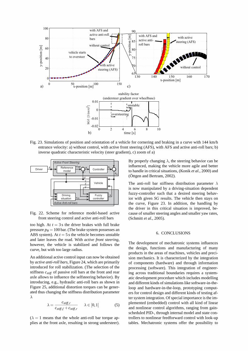
reference model. This reference model is identicalwith the expected steering behavior for normal drivingsituations with velocity-dependent behavior and in-cludes the dynamics of lateral tire forces, (Schornetal., 2005). The steering controller is a PID-controllerwith velocity-dependent parameters designed with lo-cal linear one-track models. Figure 23 shows the simu-lated resulting steering behavior for a vehicle enteringa curve with 144 km/h using a verified comprehensivetwo-track model including lateral and vertical dynam-ics. The one-track model yields in the case of station-ary cornering for the required steering angleδ relatedto the Ackermann steering angleδ0 = i l l/ρ
δ
δ0= 1+
1
v2ch
v2 = 1+SGl
v2 (2)
with
SG=l
v2ch
(under) steer gradient (3)
v2ch =
cαFcαR l2
m(cαR lR−cαF lF)characteristic velocity (4)
(cα wheel cornering stiffness,lF,R distance betweenCG and axle,F front, R rear,l = lF + lR).
Thus,(SG> 0),(SG= 0),(SG< 0) indicates under-steering, neutral steering and oversteering.
After entering the curve att = 0 s, the vehicle startsto oversteer att = 2 s because the velocity is by far
0 50 100 150
0
20
40
60
80
100
x-position [m]
y-p
osi
tion [
m] without control
with active
steering (AFS)
with AFS and
active anti-roll
bars
vehicle starts
to oversteer
a)
130 140 150 160 17065
70
75
80
85
90
y-p
osi
tion [
m]
without control
with active
steering (AFS)
x-position [m]
with AFS and
active anti-
roll bars
c)
0 2 4 6 8 10-0.02
-0.01
0
0.01
stability factor
(understeer gradient over wheelbase)
time [s]
SG
/l [1
/(m
/s)2
]
oversteering
unstable
b)
Fig. 23. Simulations of position and orientation of a vehicle for cornering and braking in a curve with 144 km/hentrance velocity: a) without control, with active front steering (AFS), with AFS and active anti-roll bars; b)inverse quadratic characteristic velocity (steer gradient), c) zoom of a)
Controllerψref.
ψ
vch
δw
δc
vxy
.
δ
λDriving
situation
Reference
model -
Vehicle
Driver
Fuzzy
controller
..
..
Active Front Steering
Active Anti-roll bars
e
Fig. 22. Scheme for reference model-based activefront steering control and active anti-roll bars
too high. At t = 3 s the driver brakes with full brakepressurepB = 100 bar. (The brake system possesses anABS system). Att = 5 s the vehicle becomes unstableand later leaves the road. Withactive front steering,however, the vehicle is stabilized and follows thecurve, but with too large radius.
An additional active control input can now be obtainedby active anti-roll bars, Figure 24, which are primarilyintroduced for roll stabilization. (The selection of thestiffnesscstiff of passive roll bars at the front and rearaxle allows to influence the selfsteering behavior). Byintroducing, e.g., hydraulic anti-roll bars as shown inFigure 25, additional distortion torques can be gener-ated thus changing the stiffness distribution parameterλ
λ=cstiff ,r
cstiff ,f +cstiff ,rλ ∈ [0,1] (5)
(λ = 1 means that the whole anti-roll bar torque ap-plies at the front axle, resulting in strong understeer).
By properly changingλ, the steering behavior can beinfluenced, making the vehicle more agile and betterto handle in critical situations, (Koniket al., 2000) and(Öttgen and Bertram, 2002).
The anti-roll bar stiffness distribution parameterλis now manipulated by a driving-situation dependentfuzzy-controller such that a desired steering behav-ior with given SG results. The vehicle then stays onthe curve, Figure 23. In addition, the handling bythe driver in this critical situation is improved, be-cause of smaller steering angles and smaller yaw rates,(Schmittet al., 2005).
6. CONCLUSIONS
The development of mechatronic systems influencesthe design, functions and manufacturing of manyproducts in the areas of machines, vehicles and preci-sion mechanics. It is characterized by the integrationof components (hardware) and through informationprocessing (software). This integration of engineer-ing across traditional boundaries requires a system-atic development procedure which includes modellingand different kinds of simulations like software-in-the-loop and hardware-in-the-loop, prototyping comput-ers for control design and different kinds of testing af-ter system integration. Of special importance is the im-plemented (embedded) control with all kind of linearand nonlinear control algorithms, ranging from gain-scheduled PID-, through internal model and state con-trollers to nonlinear feedforward control with look-uptables. Mechatronic systems offer the possibility to

Mstab
F stab,r
F stab,r
active anti-
roll bar
c ( )stiff,f λ cstiff,r( )λ
λ =1
λ =0
v
Rear Front
a)
b)
Fig. 24. Active anti-roll bars: a) schematic diagram;b) distribution parameterλ of the anti-roll barstiffness
Fig. 25. Active anti-roll bar system for roll stabiliza-tion and steering support (BMW)
include complex control algorithms, condition moni-toring and fault-diagnosis methods and require fault-tolerant components for safety-related processes.
The contribution gives an overview of the structureand design of mechatronic systems and considers var-ious embedded control functions and fault tolerance.As example for innovations the economically impor-tant area of automotive mechatronics is highlighted.Mechatronic suspensions, brake systems and steeringsystems change the design of automobiles fundamen-tally, improving functionality, safety, economy andcomfort. Similar developments can be observed forcombustion engines, trains, aircraft, machine tools,and automation components, etc. Thus, mechatronicdevelopment is an emerging area for innovative engi-neering.
REFERENCES
Ackermann, J., J. Guldner, W. Sienel, R. Steinhauserand V.I. Utkin (1995). Linear and nonlinear con-troller design for robust automatic steering.IEEEControl System Technology3, 132–140.
AIM (1999, 2001, 2003).IEEE/ASME Conferenceon Advanced Intelligent Mechatronics. Atlanta(1999), Como (2001), Kobe (2003).
Åström, K.H. and B. Wittenmark (1997).Computer-controlled Systems. Theory and Design. PrenticeHall. Upper Saddle River.
Bishop, C.M. (2002).The mechatronics handbook.CRC Press. Boca Raton.
Bradley, D.A., D. Dawson, D. Burd and A.J. Loader(1991).Mechatronics-electronics in products andprocesses. Chapman and Hall. London.
Bröhl, A. P., Ed.) (1995).Das V-Modell - Der Stan-dard für Softwareentwicklung, 2nd edn.. Olden-bourg. München.
Bußhardt, J. and R. Isermann (1993). Parameter adap-tive semi-active shock absorbers. In:ECC Eu-ropean Control Conference. Vol. 4. Groningen,Netherlands. pp. 2254–2259.
Canudas de Wit, C., H. Olsson, K.J Åström and P. Lin-schinsky (1995). A new model for control of sys-tems with friction. IEEE Trans. on AutomaticControl40, 419–425.
Chen, J. and R.J. Patton (1999).Robust model-basedfault diagnosis for dynamic systems. Kluwer.Boston.
Connor, B. (1996). Elektrische Lenkhilfen für Pkwals Alternative zu hydraulischen und elektrischenSystemen.Automobiltechnische Zeitschrift98(7-8), 406–410.
Dieterle, W. (2004). Mechatronic systems: industrialapplications and modern design methodology. In:3rd IFAC Symposium on Mechatronic Systems.Sydney, Australia.
Dorf, R.C. and R.H. Bishop (2001).Modern controlsystems, 9th ed.. Prentice Hall. Englewood Cliffs.
DUIS (1993).Mechatronics and Robotics. M. Hiller,B. Fink (eds). 2nd Conference, Duisburg/Moers,Sept 27-29.
Elmqvist, H. (1993).Object-oriented modeling andautomatic formula manipulation in Dymola.Scandin. Simul. Society SIMS. Kongsberg.
Fischer, D. and R. Isermann (2004). Mechatronicsemi-active and active vehicle suspensions.Con-trol Engineering Practice12, 1353–1367.
Fischer, D., H.-P. Schöner and R. Isermann (2004).Model-based fault detection for an active ve-hicle suspension. In:FISITA World AutomotiveCongress. Barcelona, Spain.
Gausemeier, J., D. Brexel, T. Frank and A. Humpert(1995). Integrated product development. In:3rdConference on Mechatronics and Robotics. Teub-ner, Stuttgart. Paderborn, Germany.
Gertler, J. (1998).Fault detection and diagnosis inengineering systems. Marcel Dekker. New York.

Goodall, R. (1995). Mechatronics in motion - somerailway applications. In:3rd IFAC Symposium onMechatronic Systems. Sydney, Australia.
Goodwin, G.C., S.F. Graebe and M.E. Salgado (2001).Control system design. Prentice Hall. EnglewoodCliffs.
Guzella, L. and C.H. Onder (2004).Introduction tomodeling and control of internal combustion en-gine systems. Springer. Berlin.
Harashima, F. and M. Tomizuka (1996). Mechatronics– “what it is, why and how?”.IEEE/ASME Trans.on Mechatronics1, 1–2.
Heimann, B., W. Gerth and K. Popp (2001).Mecha-tronik. Fachbuchverlag Leipzig. Leipzig.
Hiller, M. (1995). Modelling, simulation and controldesign for large and heavy manipulators. In:In-ternational Conference on Recent Advances inMechatronics. Istanbul, Turkey.
ICRAM (1995). Recent Advances in Mechatron-ics. Proceedings of International ConferenceICRAM’95, Istanbul, August 14 16.
IEC 60812 (1985).Analysis techniques for systemreliability procedure for failure mode and effectsanalysis (FMEA). International ElectrotechnicalCommission. Switzerland.
IEC 61508 (1997). Functional safety of elec-trical/electronic/programmable electronic sys-tems. International Electrotechnical Commission.Switzerland.
IEEE/ASME (1996).Transactions on Mechatronics.Vol. 1.
IFAC (2000, 2002, 2004).IFAC-Symposium onMechatronic Systems: Darmstadt (2000), Berke-ley (2002), Sydney (2004). Elsevier. Oxford.
IFAC-T.C 4.2. (2000). IFACTechnical Committee on Mechatronics Systems.http://rumi.newcastle.edu.au/reza/TCM/.
IMES (1993).Integrated Mechanical Electronic Sys-tems Conference (in German) TU Darmstadt,March 2-3. Vol. Fortschr.-Ber. VDI Reihe 12.VDI-Verlag. Düsseldorf.
Isermann, R. (1996). Modeling and design methodol-ogy of mechatronic systems.IEEE/ASME Trans.on Mechatronics1, 16–28.
Isermann, R. (1997). Supervision, fault-detection andfault-diagnosis methods. an introduction.ControlEngineering Practice5(5), 639–652.
Isermann, R. (2000). Mechatronic systems: conceptsand applications.Trans. of the Institute of Mea-surement and Control.
Isermann, R. (2003).Mechatronic Systems. (Germanedition: 1999). Springer. Berlin.
Isermann, R. (2005).Fault diagnosis and fault toler-ance. Springer. Heidelberg, Berlin.
Isermann, R. and U. Raab (1993). Intelligent actuators- ways to autonomous actuating systems.Auto-matica29(5), 1315–1331.
Isermann, R., K.-H. Lachmann and D. Matko (1992).Adaptive Control Systems. Prentice Hall Interna-tional UK. London.
Isermann, R., R. Schwarz and S. Stölzl (2002). Fault-tolerant drive-by-wire systems.IEEE ControlSystems Magazine(October), 64–81.
Isidori, A., Ed.) (1999).Nonlinear Control Systems II.Springer. London.
Johansson, R. and Rantzer, A., Eds.) (2003).Nonlin-ear and hybrid systems in automotive control.Springer. London.
Jonner, W.D., H. Winner, L. Dreilich and E. Schunck(1996). Electrohydraulic brake system - the firstapproach. In:SAE Technical paper Series. num-ber 960991. Warrendale.
Kiencke, U. and Nielsen, L., Eds.) (2000).Automotivecontrol systems. For engine, driveline and vehi-cle. Springer. Berlin.
Kitaura, K. (1986). Industrial Mechatronics (inJapanese). New East Business Ltd.
Konik, D., R. Bartz, F. Bärnthol, H. Brunds andM. Wimmer (2000). Dynamic drive - the new ac-tive roll stabilization system from bmw group.In: Proceedings of AVEC 2000, 5th InternationalSymposium on Advanced Vehicle Control.
Kyura, N. and H. Oho (1996). Mechatronics – anindustrial perspective..IEEE/ASME Trans. onMechatronics1, 10–15.
Lückel, J., Ed.) (1995).Third Conference on Mecha-tronics and Robotics. Paderborn, Oct. 4-6. Teub-ner. Stuttgart.
McConaill, P.A., Drews, P. and Robrock, K.-H., Eds.)(1991). Mechatronics and robotics. ICS Press.Amsterdam.
Mechatronics (1991).An International Journal. Aimsand Scope. Pergamon Press. Oxford.
Merker, T., J. Wirtz, M. Hiller and M. Jeglitzka (2001).Das SL-Fahrwerk..ATZ - Automatisierungstech-nische Zeitschrift. Special Issue: Der neue Mer-cedes SLpp. 84–91.
Morari, M. and F. Zafirov (1989).Robust processcontrol. Prentice Hall. Englewood Cliffs.
Onodera, K. (1997). Effective techniques of fmea ateach life-cycle stage. In:1997 Proceedings: An-nual Reliability and Maintainability Symposium.IEEE. pp. 50–56.
Otter, M. and C. Cellier (1996). Software for modelingand simulating control systems. In:The ControlHandbook(W.S. Levine, Ed.). CRC Press. BocaRaton.
Öttgen, O. and T. Bertram (2002). Influencing vehi-cle handling through active roll moment distribu-tion. In: Proceedings of AVEC 2002. 6th Interna-tional Symposium on Advanced Vehicle Control.Hiroshima, Japan. pp. 129–134.
Pfeufer, T., T. Landsiedel and R. Isermann (1995).Identification and model-based nonlinear con-trol of electro-mechanical actuators with friction.In: IFAC-Workshop Motion Control. Munic, Ger-many.
Schmitt, J., R. Isermann, M. Börner and D. Fischer(2005). Model-based supervision and control of

lateral vehicle dynamics.Control EngineeringPractice.
Schöner, H.P. (2004). Automotive mechatronics.Con-trol Engineering Practice12, 1343–1351.
Schorn, M., J. Schmitt, U. Stählin and R. Isermann(2005). Model based braking control with sup-port by active steering. In:Proceedings of the16th IFAC World Congress 2005, Prague, CzechRepublic.
Schweitzer, G. (1992). Mechatronics – a concept withexamples in active magnetic bearings.Mecha-tronics2, 65–74.
Semmler, S., R. Isermann, R. Schwarz and P. Rieth(2002). Wheel slip control for antilock-brakingsystems using brake-by-wire actuators. Vol. SAE2002-01-0303. Detroit, USA.
Slotine, J.J.E. and L. Weiping (1991).Applied nonlin-ear control, Chapter 7 in Sliding Control. Pren-tice Hall. Englewood Cliffs.
Spong, M.W. and M. Vidyasagar (1989).Robust dy-namics and control. J. Wiley. New York.
STARTS GUIDE (1989).A guide to methods andsoftware tools for the construction of largereal-time systems.. National Computing Centre.Manchester.
Stoll, U. (2001).Sensotronic brake control (SBC). Vol.VDI-Ber. 1646. VDI. Düsseldorf.
Stölzl, S. (2000).Das elektrohydraulische Bremssys-tem von Contintental Teves. Vol. Fortschr.-Ber.VDI Reihe 12. VDI-Verlag. Düsseldorf.
Stölzl, S., R. Schwarz, R. Isermann, J Böhm, J. Nelland P. Rieth (1998). Control and supervision ofan electromechanical brake system. In:FISITAWorld Automotive Congress, The Second Centuryof the Automobile. Paris, France.
Storey, N. (1996).Safety-critical computer systems.Addison Wesely Longman Ltd.. Essex.
Tomizuka, M. (1995). Robust digital motion controllerfor mechanical systems. In:International Confer-ence on Recent Advances in Mechatronics. Istan-bul, Turkey.
Tomizuka, M. (2000). Mechatronics: from the 20thto the 21th century. In:1st IFAC Conference onMechatronic Systems. Elsevier, Oxford. Darm-stadt, Germany.
UK Mechatronics Forum (1990,1992, 1994, 1996, 1998, 2000, 2002).Confer-ences in Cambridge (1990), Dundee (1992), Bu-dapest (1994), Guimaraes (1996), Skovde (1998),Atlanta (2000), Twente (2002).
Utkin, V.I. (1977). Variable structure systems withsliding mode: a survey.IEEE Trans. on Auto-matic Control22, 212–222.
van Amerongen, J. (2004). Mechatronic educationand research – 15 years of experience. In:3rdIFAC Symposium on Mechatronic Systems. Syn-dey, Australia. pp. 595–607.
VDI 2206 (2004).Entwicklungsmethodik für mecha-tronische Systeme. Beuth Verlag. Berlin.


![MECHATRONIC DESIGN - A PORT-BASED APPROACH · ent domains’ [1]. This definition of mechatronics indicates a num-ber of important aspects of mechatronics. Optimal design implies](https://img.dokumen.tips/doc/110x75/5ebad285f2dd182d6c4be398/mechatronic-design-a-port-based-approach-ent-domainsa-1-this-deinition.jpg)