Embed Size (px)
Citation preview

Scholars' Mine Scholars' Mine
Masters Theses Student Theses and Dissertations
1972
Mechanism of UAL₃ to UAL₄ transformation Mechanism of UAL to UAL transformation
Ling Ping Lee
Follow this and additional works at: https://scholarsmine.mst.edu/masters_theses
Part of the Metallurgy Commons
Department: Department:
Recommended Citation Recommended Citation Lee, Ling Ping, "Mechanism of UAL₃ to UAL₄ transformation" (1972). Masters Theses. 5054. https://scholarsmine.mst.edu/masters_theses/5054
This thesis is brought to you by Scholars' Mine, a service of the Missouri S&T Library and Learning Resources. This work is protected by U. S. Copyright Law. Unauthorized use including reproduction for redistribution requires the permission of the copyright holder. For more information, please contact [email protected].

MECHANISM
BY
the Graduate
T27ll 41 pi.\gt"S
c. I
ABSTRACT
The UA14 compound which forms during the peritectic
reaction, Liquid + UA13 - UA14 , has a long needle-like
shape and a characteristic morphology of fish-tail when
ii
cut along the long axis. It has an internal core of another
phase when cut perpendicular to the needle axis. Because
of the interesting similarity between UA13 and UA14 crystal
structures, the peculiar UA14 morphology could be explained.
The mechanism of UA13 to UA14 transformation is identified
as shear and diffusion controlled transformation.

iii
ACKNOWLEDGEMENTS
The author wishes to express his appreciation to
Dr. H. P. Leighly, the advisor in this work. He is also
indebted to Dr. B. L. Bramfitt for his providing the alloy
used in this investigation. He also wishes to thank
Dr. J. D. Bucci for his help in the x-ray diffraction work.

TABLE OF CONTENTS
~~~~<:~ ••••••••••••••••••••••••••••••••••••••••••••
~C:FC!l~~I>C;~~~- •••••••••••••••••••••••••••••••••••
iv
PAGE
ii
iii
LIST OF FIGURES..................................... vi
LIST OF TABLES ••••.•••...•••••.•..•.•..••••.....•.•.
I.
II.
III.
IV.
v.
INTRODUCTION • ••••••••••••••••••••••••••.•••••
BACKGROUND • ••••••••••••••••••••••••••••••••••
EXPERIMENTAL METHOD .......................... .
A. Preparation of the Alloy •••.•• . . . . . . . . . . . B. X-Ray Diffraction •••.•••.....• . . . . . . . . . . . c. Metallographic Examination •••• . . . . . . . . . . . D. Electron Microscope and Scanning
Microscope Examination •••...•••••••.•
RESULTS AND DISCUSSION •••••••••••••••••••••••
A. Defining of the Needle Axis and the
Structural Transformation •.••••••••.• . . . . B.
c.
Fish-Tail and Parallelogram Morphology ..•
Anisotropic Property of UA14 ••.•.•..•••••
~~It~ ••••••••••••••••••••••••••••••••••••••
vii
1
3
8
8
9
10
11
12
12
19
26
29
REFERENCES • ••••••••••••••••••••••••••• • • • • • • • • • . • • • .. 30
VITA ••••••••••••••••• ••• • • • • • • • • • • • • • • • · • • • • • · • • • • • 31

v
APPENDICES. • • • • • . • • • • . . • • • • • . • • • • • • • • . • • • • • . • • . • • . • . • 32
I. BOND DISTANCES •••••••••••••••••••••••••••••••• 32
II. FISH-TAIL ANGLES ••.••••••••••••••••••••••••••• 34

vi
LIST OF FIGURES
Figure Page
1. Aluminum- Uranium System........................ 4
2a. Unit Cell of UA14 projected Along a axis......... 5
2b. Comparison of Two Unit Cells of UA14 , with the
Eight-Fold Al Atoms omitted, and a Unit Cell of
UA13 • • • • • • • • • • • • • • • • • • • • • • • • • • • • • • • • • • . • • • • • • • • • 5
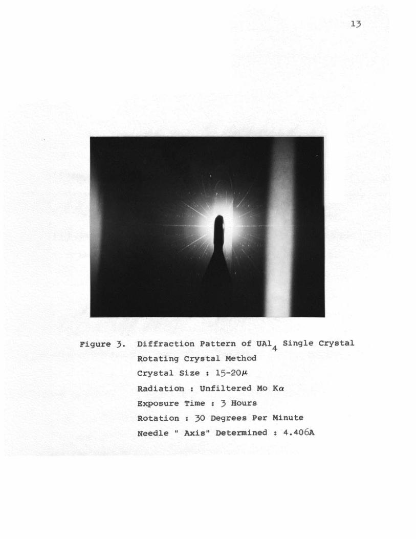
3. Diffraction Pattern of UA14 Single Crystal....... 13
4. The Crystal Structure Relationship Between UA13
and UA14 • • • • • • • • . • • • • • • • • • • . • • • • • • • • • • • • . • • • • • • • • 15
5· Photc.:.micrograph Showing the Long Needle Morphology
of UA14 crystals with A Fish-Tail and A
Parallelogram Morphology......................... 20
6. The Steps of UA13 to UA14 Transformation ••••••••••
7. The Sketch of the Fish-Tail Angle Calculated •••••
8a. UAl crystals Showing Different Contrast in 4
22
25
Polarized Light.................................. 27
8b. After rotation. • • • • • • • • • • • • • • • • • • • • • • • • • • • • • • • • . . 27

LIST OF TABLES
Table
I. UAl lattice parameter and its relation to 4
the corresponding UA1 3 parameter ••••••••••••••••
II. 1~e crystal structure characteristics of UA13
vii
Page
16
and UA14 compound • • • • • • • • • • • . • • • • • • • • • • • • • • • • • • • 32

I. INTRODUCTION
Aluminum-uranium alloy has been used extensively in
fuel elements for nuclear reactors. Fabrication of these
1
fuel elements requires that the cast ingot be hot rolled into
a thin plate. Poor rolling characteristics are exhibited
due to the presence of an excess of the inter.metallic cam-
pound, UA14 , when the alloy contains more than 20 weight
percent uranium.
It is the purpose of this investigation to study the
mechanism of formation of UA14 from its parent phase, UA1 3 ,
by the peritectic reaction, Liquid + UA13 --UA14 , at 730°C
in alloys having more than 18 weight percent uranium.
The UA14 crystals have a peculiar microstructure when
examined in photomicrographs. They are long needle-like in
one direction. A rectangular shape with an internal core of
an entrapped phase may be seen when examined in the direction
perpendicular to the long axis. If the sectioned face is no
longer perpendicular to the long axis, then the section and
the core will be a parallelogram. When the crystal has been
sectioned along its long axis, a fish-tail with a deep re-
entrant angle of another phase will be revealed. The fish
tail is the UA14 which enclosed the internal core before
sectioning. Apparently, the deep re-entrant angle of another
phase is the remaining internal core.

2
In fact, most microstructures show UA14 with this
fish-tail or the parallelogram with internal core on micro
scopic examination. It is very interesting that with this
characteristic morphology, the UA14 compound can be derived
from UA13 structure with same calculation and interpre
tation. A mechanism of transformation has been developed
to explain the UA14 structure as it is derived from UA13•
This mechanism is based on a similar relationship between
the UA13 structure and UA14 structure.
Experimental x-ray diffraction, electron microscopy,
scanning microscopy, and metallography were undertaken to
reveal the assumed mechanism of transformation.

3
II. BACKGROUND
The aluminum-uranium equilibrium diagram was first
investigated by Gordon and Kaufman (1) in 1950 and later
was modified by Saller and Rough (2). This diagram is shown
in Figure 1. The peritectic reaction, Liquid + UA1 3 - UA14 ,
occurs at 730°C during solidification when the alloy con-
tains more than 18 weight percent uranium. The aluminum
rich end of the aluminum-uranium equilibrium diagram has
been studied extensively so there is no real disagreement
about reaction temperature or compositions in this system.
The first syllable of the word "peritectic" is derived
from the Greek prefix, "peri", which means surrounding.
A peritectic reaction implies that one solid phase grows
around a second solid phase and at the expense of the
second phase.
Borie (3) found in 1951, by using the Weissenberg
method, that the small black needle-like UA14 compound had
body-centered orthorhombic structure with four formula
weight per unit cell and its lattice parameters are: a=4.41A,
b=6.27A, c=l3.71A as shown in Figure 2a. While the parent
phase, UAl , has AuCu type ordered cubic structure with lat-3 3
tice parameter of a 0 =4.26A. He had also found a relation-
ship between UA13 structure and UA14 structure as shown in

4
ATOMIC PER CENT URANIUM
0 1.24 2.72 4.64 7.03 I 0.2 14.5 20.9 31.3 50.1 100
u 0
LLJ a: :::> t- tOOO<( a:: LLJ a. ~ uJ 1-
0 10
I I
I I
I
1590°C /, ... ,
/ \ / \
/ \ ,' \
Ll QUID I Lt UAL2 \ I \
(60 / 1350°C \\
/ \ / ' / \
/ /1 UALzL\
/ /
/ I
I 1 L+ UAL3
N ..J <(
I I
I
:::> +-rt')
..J <( :::>
(Ja) 1 730°C
I 1 L + UAL4
AL _,. UAL4
I
c
20 30 40 50 60 80 90 100
WEIGHT PER CENT URANIUM
Figure 1. Aluminum - Uranium System

b
c
Figure 2a. Unit Cell of UA14 Projected Along a Axis
Figure 2b. Comparison of TWo Unit Cells of UA1 4 , with
the Eight-Fold Al Atoms omitted, and a
Unit Cell of UA13. After Borie.
Uranium Atoms Shown in Heavy outline and
are Shaded.
5

Figure 2b. There is interesting similarity between these
two structures. It is very clear that the UA14 unit cell
can be formed, except for the eight-fold aluminum atoms,
from plates of UA13. The plates have their faces as (110)
planes of the cubic structure and a thickness equal to the
spacing of the (110) planes of UA13. The normal to the
plates is the c axis of the UA14 structure. Actually the
UA13 cell would have to be slightly expanded for this con
struction to be possible. However, the cubic symmetry is
6
almost perfectly maintained. He concluded that the UA14
structure may be thought of as UA13 plates held together by
extra aluminum atoms.
In 1968, Leighly and Bramfitt (4) studied the solidifi-
cation and segregation in cast aluminum-uranium alloys by
metallographic examination. They published a series of
photomicrographs showing the UA14 and some retained UA13
microstructures. Most of those UA14 crystals have the
characteristic morphology of either the long needle with
fish-tail or the parallelogram with an internal core. The
UA13 crystals, which were retained by fast cooling, had
cubic shape on account of its isotropic properties. Same of
the UAl particles exhibited cracks which were caused by 4
either thermal stresses during solidification or lattice
strain during the peritectic transformation. However, the

most important result which they obtained was the revela-
tion of the second phase in the internal core of UAl 4
7
crystals. By electron microprobe analysis, they presented
both electron image and uranium X-ray image micrographs of
a UA14 crystal with the internal core showing that it was
pure aluminum, i.e., solid solution of a aluminum with
slight solubility of uranium which can be neglected. With
this discovery, it is positively known that the internal
core of the UA14 crystal is not the retained untransformed
UA13 crystal.
Runnalls and Boucher (5) also showed the existence
of an internal core in UA14 compound by its lower measured
density compared with the calculated theoretical density of
UA14 • They found that a transformation existed in the UA14
crystals at a temperature very near the eutectic temperature
of aluminum and UA14 • But they did not find any change in
crystal structure or lattice parameter, so they attribute
the transformation to a rearrangement or clustering of
vacancies within the UA14 crystals. Leighly and Bramfitt
(4), by their discovery of the aluminum phase of the
internal core in the UA14 compound, suggested that the
transformation in UAl could be due to the independent 4
solidification of the liquid core within the UA14 particles.

8
III. EXPERIMENTAL METHOD
A. Preparation of the Alloy
The alloy used in this investigation was 30wt% U-Al
alloy which was produced by Bramfitt (6). In producing this
alloy only pure materials were used. The aluminum was taken
from high-purity notch-bar ingots of the following analysis
( weight percent ):
Cu Fe Si
0.003 0.001 0.001
Mg
0.002
Zn
0.001
other Al balance
0.0001
Actual analysis of the uranium metal was not available, but
the typical analysis of the commercial-grade depleted
uranium metal was the following:
Al Co C Mg N 0
0.01 0.01 0.03 0.01 0.01 0.04
Si Fe+Ni
0.025 o.os
other U balance
0.032 99.783
Before weighing the charge for the furnace the pure uranium
metal was electropolished to remove any oxide layer. The
material was stored under liquid ethyl ether to assure oxida
tion protection after electropolishing and until melting.
A vacuum-induction furnace was used in melting and
casting. The melting chamber contained a graphite thermo
couple sheath, a graphite stirring rod and a graphite stopper
rod. A thermocouple was inserted into the thermocouple
sheath to measure the temperature of the melt. The melting

9
of the charge was observed visually through a sight tube
located on the water cooled furnace cover. The pressure in
the furnace was maintained between 10-4 and 10-5 torr during
the melting and pouring cycle. The pouring temperature for
this alloy was 130°C above liquidus, i.e.,at 1080°C. Stir-
ring of the melt was performed before casting. The stirring
action aids in both the alloying and homogenization of the
melt. After the pouring temperature of the melt was reached,
the melt was cast into a l-inch-diameter graphite mold which
was within the vacuum chamber. Pouring was done through the
bottom of the melting crucible by lifting the graphite
stopper rod. A vacuum was maintained during the solidifi-
cation to prevent further oxidation of the alloy. When the
temperature within the furnace reached room temperature,
the system was exposed to the atmosphere.
B. X-Ray Diffraction
From the U-Al phase diagram it is apparent that Al and
UAl are the two phases in equilibrium in this cast 30% U-Al 4
alloy. In order to isolate the UA14 compound for X-ray
diffraction, the UA14 crystals had to be separated from the
surrounding Al phase. Metallographic examination showed
that the alloy had randomly dispersed UA14 needles surrounded
by regions of aluminum solid solution. Aluminum can be

10
dissolved in basic solutions such as KOH and NaOH. The
UA14 crystals were resistant to these solution. Borie (3)
obtained the UA14 crystals for his research by reacting the
alloy with NaOH solution. Runnalls and Boucher (5) used
the same method by immersing the alloy in 2N KOH solution
to dissolve the aluminum rich matrix and free the remaining
UA14 crystals. In this investigation, 2N KOH was also used
for dissolving aluminum. Several small pieces of the alloy
were cut from the ingot. These samples were ~ersed in
the KOH solution for about two hours to dissolve the alumi
num. Many small black UA14 needles remained in the solution.
These needles had an average length of 15-20~. One of the
larger UA14 needles was carefully picked up using a low
power microscope. The single crystal was then transferred
into a quartz capillary tube of 0.3mm diameter. In order
to define the long axis of the UA14 crystal, the single
crystal was examined by the rotation x-ray diffraction
method. The quartz capillary was mounted on Burger's
precession camara for three hours' exposure. A diffraction
pattern was obtained as shown in Figure 3-
c. Metallographic Examination
Another piece of alloy cut from the ingot was prepared
for metallographic examination. This specimen was rough

11
polished with emery paper from 320 to 600 grit and given
final polish with 3 micron diamond paste. With the spec
imen unetched, photomicrographic pictures were first
taken using polarized light to show the different contrast
of the anisotropic UAl4 crystals. Then the specimen was
etched in 2N KOH solution about 45 seconds for examination
in white light. Photographs showing the long needle fish
tails were taken randomly for statistical study. The deep
re-e~trant angle between the fish-tail is very significant
in the mechanism of transformation. The angles were
measured with a protractor.
D. Electron Microscope and Scanning Microscope Examination
The UA14 single crystals were obtained by the same
method as described in x-ray diffraction section. several
single crystals still in the KOH solution were sucked up
by a eye dropper. This was then released on a carbon
film on a 100 mesh specimen grid for electron microscope
examination. Diffraction patterns were taken for the pur
pose of orientation determination. Unfortunately, no par
ticular results were obtained. Photomicrographic pictures
were also taken by scanning microscope but with no special
contribution to this investigation.

12
IV. RESULTS AND DISCUSSION
A. Defining of the Needle Axis and the Structural Transfer-
mat ion
Figure 3 is the X-ray diffraction pattern of the UAl 4
single crystal by the rotation crystal method. The radi
ation used for this pattern was unfiltered Mo Ka radiation.
The crystal had 30 degrees rotation per minute. In order
to find the lattice parameter of the long axis of the needle.
the UA14 single crystal was put with its long axis in
alignment with the central line of the camera. The needle
axis corresponded to the rotation axis, so that the x-ray
beam was directly on the needle and at 90 degrees with the
long axis. The lattice parameter along the needle axis
was determined from this diffraction pattern to be 4.406A.
The most recent information on UA14 lattice parameter
found in literature was given by Borie (3) : a=4.41A,
b=6.27A, c=l3.71A. It is apparent that the lattice
parameter of the long axis determined from this film had
nearly the same value as Borie 1 s value for the '1 a" axis.
It can be concluded that the UA14 needle crystal had its
long axis corresponding to UA14 ''a" axis. This result is
very significant in the mechanism of UA13 to UA14 transfor
mation.
lliffraetion Pattern of
. f(.otatlng c.eyst.a.l Metm,od
Cr'Jstal Si~ ze : 15 .... 30~-t
Rad:tatio:n ; Un.:filtered ita
Exposuret lJ'im:e : 3 Hours
· ·- aotat.iein .· ·.':~ 50 ~goree$ fer Minute
Needl.e ~~ Axia!J Determine-a :t 4 .. 406A
····· .. •·1,

14
Borie (3) suggested that the UAl structure could be 4
thought of as UA1 3 plates held together by extra aluminum
atoms. This model implied that the UA14 axis system can
be derived from UA1 3 axis system. Figure 4 shows the axis
relationship between UA13 and UA14 structures. Actually,
the UA14 unit cell can be formed by four UA1 3 unit cells,
if the origin of UA1 4 unit cell was put at an edge-centered
position in UA1 3 cubic structure as point 0' shown in Figure
4. The UA14 coordinate position can be obtained by 45°
rotation of UA1 3 coordinate axis about its [100] direction.
With [100] direction unchanged, [Oll] UA1 3 becootes [010]
UA14 and [011] UA13 becomes [001] UA14 • The UA14 lattice
parameter in a, b and c axis is nearly equal to ao, v'2ao
and 2v'2a , respectively, where ao is the lattice parameter 0
of UA13 • In fact, as denoted by Borie (3), there is a
slight expansion of the UAl structure to obtain the real 3
atom position in UA14 • These expansions are 1.035, 1.042
and 1.038 in a, b and c axis of UA1 4 structure respectively,
as shown in Table I, so that the u-u separation in UA14 is
about 3.5 percent greater than it was in UA13 . ( detailed
calculation in Appendix I }. The mechanism of lattice
deformation will be described in detail as follows:
In Figure 4, the slab A and A' are the (011) plates

UAl 0 ( xl_, X x3 ) UAl ( xi, x2, X' ) . 2' 3 4 3 X and X' Perpendicular to the Paper
l 1 Large Circle : u Small Circle Al
Slab A : vertical Line Area
Slab A': Horizontal Line Area
Figure 4. The Crystal Structure Relationship Between
UA1 3 and UA14
15

TABLE I
UA1 4 lattice parameter and its relation to the
corresponding UA1 3 parameter
UA14 lattice
axis
a
b
c
Direction
in UA1 3
(100] UA13
[ Oll] UA13
lattice
parameter
just after
shearing,
A
4.26
6.02
12.04
real Expansion
lattice
parameter
in UA14 ,
A
4.41 1.035
6.27 1.042
13-71 1.138
16

17
which have a thickness of (011) planes. In order to get
the real structure of UA14 _. the adjacent UAl) (011) plate_.
slab A in Figure 4, has to shift up or down in [lll] direc
tion or in [lll] direction at a distance of ~[111] UA1 3 on
(011) plane. Borie (3) mentioned these plates (110) plates
in UA1 3 • Although (110) plates are the same as (011) plates
in UAL3 cubic structure, but since "a" axis should be fixed
and in order to correspond to Figure 4, the plates should
be (011) plates. After this shear deformation the main part
of the UA14 structure, except the eight-fold aluminum atoms
which are the B line atoms in Figure 4, is obtained. In
fact, the shear deformation can be done fairly well in
reverse by shearing the slab of UA14 [b/2, a/2] or
[b/2, a/2] in its own direction to get UA13 structure.
During the shearing process as described above the
region between the (011) plates has an great expansion of
1.27. Because of more aluminum atoms contained in each
UA14 unit cell than in UA1 3, four more aluminum atoms must
to be added in each UA1 4 unit cell to make a rearrangement
with the original B line atoms in Figure 4 so as to produce
the real UA14 structure. These atoms are just those so
called eight-fold aluminum atoms. It is apparent that these
four aluminum atoms come from liquid solution during the
peritectic reaction.

18
The plane relationships are : (100) UAl becomes
' (100) UA1 4 , (002) UA14 is made of half (022) and half (o22)
of UA13, (020) UA1 4 is made of half (022) and half (022) of
UA13 . Because of the fact that the UA14 structure has
different origin than UAl~ structure and each UAl unit cell / 4
is made of four UA1 3 unit cells, there is no simple mathe-
matical equation to express the plane and coordination
relationship.
With the description shown above, the conclusion can
be made that the UA13 to UA14 transformation is basically
a shear dominated transformation. The habit plane would
be the (220) plane which becomes (002) in UA1 4 • When the
alloy goes through the peritectic temperature the peritectic
reaction, L + UA13 - UA14 , happens first by shearing the
(011) plates of UA1 3 in its [111] or [lll] direction.
It is followed by an expansion of the region between the
plates to make enough space for four more aluminum atoms
to diffuse in from the liquid. So the peritectic reaction
is both a shear and diffusion controlled transformation.
In order for the transformation to continue the
plates have to shear up again to let aluminum atoms diffuse
in. In fact, the shearing of the plates in UA13 corresponds

to [b/2,a/2] or [b/2,a/2] in UAl as ment.ioned above. 4
Since [100] UA1 3 is also [100] UA1 4 , each time the UA1 3
plates shear up in [100] direction that means UA14 grows
one step also in [100] direction. In this process of
transformation aluminum atoms can only diffuse in [100]
direction of UA14 • This means that during the transfor
mation UA14 grows in its [100] direction.
B. Fish-Tail and Parallelogram Morphology
19
Figure 5 shows the long needle morphology of UA1 4
crystal with a fish-tail and the deep re-entrant angle of
another phase. A parallelogram with an internal core is
also shown. This parallelogram is a section of the crystal
nearly perpendicular to the needle axis. Thirty analogous
pictures showing this fish-tail morphology were taken
randomly for statistical purpose. These angles ranged
from 2 to 21 degrees. ( as shown in Appendix II )
Since the UA13 to UA14 transformation is a shear and
diffusion controlled transformation as described in
previous section, the peculiar morphology of the UA1 4
crystals could be explained as follows:
When the 30wt% U-Al mol ten alloy is cooled below t.he
liquidus temperature, at about 940°C, the UA1 3 dendritic

.Figure 5. Photomicragrap!l Show in<.;; the . L<i>h.9 Needle
Morphology of UA14 Crysta.ls with A Fish
Tail and A Parallelogram Morphology.
so ox
20

21
formation and growth should occur. These UA13 dendrites
have cubic morphology in their growth direction on account
of their isotropic properties. This cubic morphology has
been found by Leighly and Brarnfitt (4) in their U-Al alloy
study. Also because of their Aucu3 type ordered cubic struc
tural characteristics the dendrites should have {110}
planes as their prismatic faces. Figure 6 shows step by
step that a UA13 dendrite transforms to UA14 needle. When
the alloy temperature goes through peritectic temperature
the transformation will begins first by a shearing at the
edge of the dendrite and progresses along the long axis.
This is by virture of the temperature gradient along the
dendrites. The UA13 (011) plates will first shear from
the outer rim of the crystal, because of the lower temper-
ature at the outer rim. Also because that the outer rim
which is surrounded by liquid alloy has more space to
expand. The peritectic reaction starts by shearing and
expanding of the outer rim of the UA13 crystal. Then alu-
minum atoms diffuse in to make the first section of UA1 4
crystal as shown in Figure 6. As described earlier, the
sheared part is on (011) plates of UA13 , the shearing cor
responds to [b/2,a;2] or [b/2,a/2] in UA1 4 • Where [b/2,
a/2] corresponds to ~ [ell] UA13 and [ b/2, a/2] corresponds
to ~ [ ll1] in UA13. In order to maintain the "a" axis as

22
[ -] [010] II\ t AFTER [ITI]
UAL3 EJ - [001] a--UA~
MOLTEN AL -.:1 t [100]
I I UAL4 I 1 UA~ I I I
I I I
=:> I I => I I
UAL3 I I I I I UAL3 1 I UAL31 I I I 1
EXPANSION-- I I - I I I I I I I I I I I I ---+(001] I I
[010]
t __..[001] D
I [100]
Figure 6. The Steps of UAl 3 to UA1 4 Transformation

25
the needle axis in UA1 4 , the outer rim of UA13 will shear
alternately in ~ [1111 and ~ [lll J step by step so that the
growing has a zig-zag way along [lOOj direction. This means
that if the plates first shear in ~[111] then they will
shear .~ [111] next so as to come back to [100] direction.
After shearing, there is an expansion between the plates.
to let aluminum atoms diffuse in. The expansion of the
newly formed UA14 crystal also happens at this time. The
expansion respective to the "b" and 11 C" axis is the same on
each step of shearing_, i.e., 1.042 in "b" axis and 1.038
in "c" axis. Because of the fact that there is larger ex-
pans ion in "c" direction than in ''b" direction the resulting
intersection morphology of the UA1 4 needle will no longer be
a square shape as it was in UA13 before transformation.
A slight rectangular shape will be the result if the section
is just perpendicular to [100] direction.
In the fashion as indicated above, if the ''b" or "c"
direction in UA14 is perpendicular to the paper in Figure 6,
the fish-tail will grow in "a" direction, i.e., [100] direc-
tion until all the UA13 transforms to UA1 4 . Gradually, the
UA1 4 crystal becomes a long needle with a fish-tail in one
end. The angle of separation in the fish-tail is the result
of expansion in each step. The molten aluminum atoms

24
move into the internal pocket within the fish-tail. If
one looks down the crystal in [100] direction, the rectangu
lar shape UA14 with an internal core will appear. If the
section is not perpendicular to the long axis, the
parallelogram shape will appear.
With the description shown above, the angle 9 between
the fish-tail becomes calculable. Figure 7 is a schematic
drawing used in calculation. Since the distance of the
separation between the fish-tail is the result of expansion
and the depth of the angle is the result of a/2 UA1 4 shear
in each step, the tangent of the half angle can be obtained
by simple geometrical method. If the "b" direction is
perpendicular to the paper:
tan 8/2 = half value of the expansion in half c
direction I shear in a direction
= ~(13.71/2 - 12.04/2}/2.205
8/2 = 10.8°
8= 21.6°
If the "c" direction is perpendicular to the paper:
tan 0/2 = half value of the expansion in b direction/
shear in a direction
= ~(6.27 - 6.02)/2.205
IJ/2 = 3-25 °
fJ= 6.5°

25
1 ~ { 1~71 -6.02)
[2(6.2.7- 6.02)
~
I l .5t <t ~ :::::::> -<t
oiN ::>
l t:l\ N
j
(oo 1] [010]
l l (100) Qoo)
Figure 7. The Sketch of the Fish-Tail Angle Calculated
26
Of the two values shown above, 21.6° is more important and
significant. Because the greater expansion between the
plates .is a main step in the transfonnation so that the
aluminum atoms can diffuse in. If we compare the measured
value with this calculated value, it is apparent that none
is larger than 21.6°. This is because the sectioning
along the long axis is not exactly parallel to the long
axis.
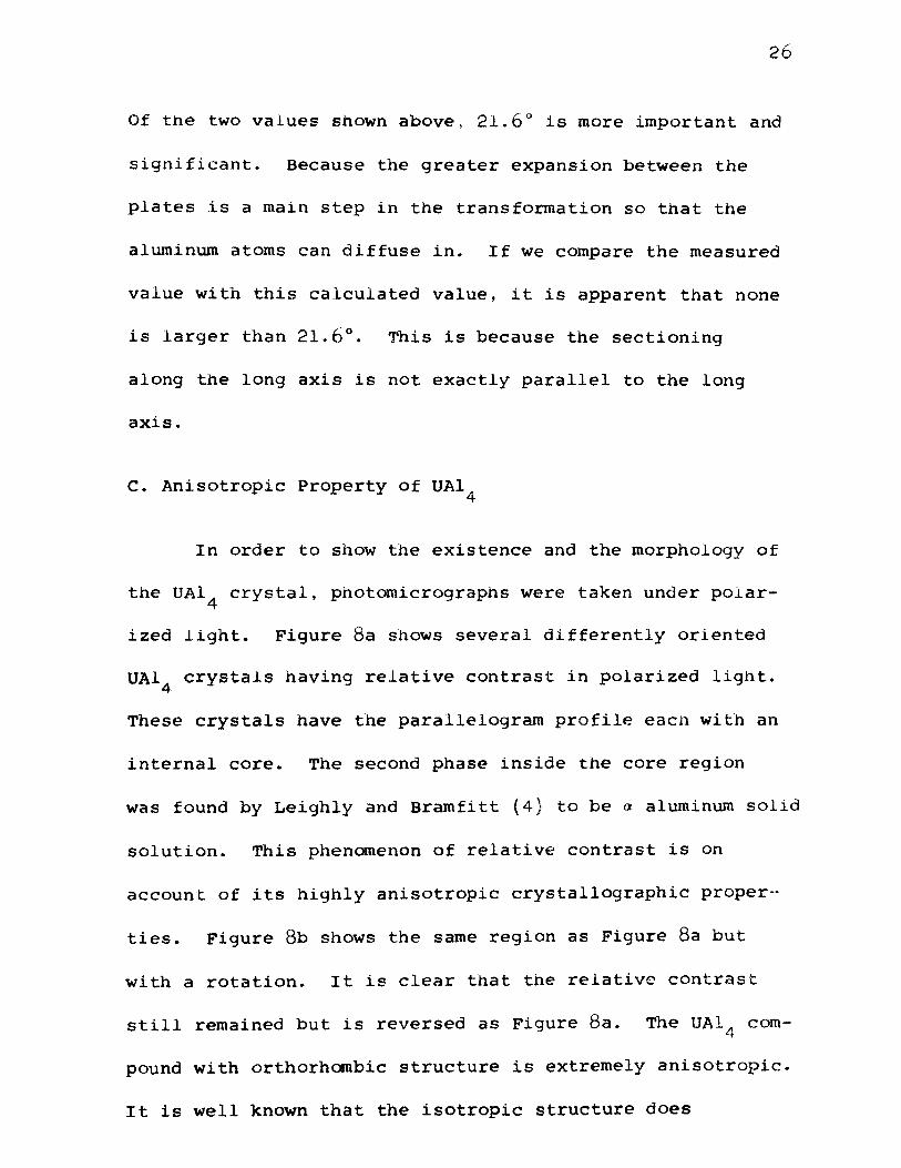
c. Anisotropic Property of UA14
In order to show the existence and the morphology of
the UA14 crystal, photomicrographs were taken under polar
ized light. Figure 8a shows several differently oriented
UA14 crystals having relative contrast in polarized light.
These crystals have the parallelogram profile eacn with an
internal core. The second phase inside the core region
was found by Leighly and Bramfitt (4) to be a aluminum solid
solution. This phenomenon of relative contrast is on
account of its highly anisotropic crystallographic proper-
ties. Figure 8b shows the same region as Figure 8a but
with a rotation. It is clear that the relative contrast
still remained but is reversed as Figure Sa. The UA14 com
pound with orthorhombic structure is extremely anisotropic.
It is well known that the isotropic structure does

27
b, after rotation
Figure S. UA14 C.rystals Showing Different Contrast
in Polarized Light. 250X

28
not change its contrast in polarized light. Therefore the
crystals can not be UAL~ but must be UA14 . /

29
V. SUMMARY
The morphology of the UA1 4 crystals resulting from
the peritectic reaction, Liquid + UA13 ~ UA14 , found in
aluminum-uranium alloys containing more than 18wt% uranium
has been explained~ The fish-tail form of the UA1 4 crys
tals observed in the microstructure is the result of a
shear and diffusion controlled transformation in which
(011) UA1 3 plates undergo the shear mechanism (011) [lll]
or (011) (lll] for a distance of ~[111]. Other observed
microstructures can be explained by this mechanism.
The shear mechanism requires that the "a" direction
must coincide with the long axis of the crystal which has
been observed.
REFERENCES
l. A. R. Kaufman and P. Gordon, "Uranium - Aluminum and
Uranium- Iron", Trans. AIME, 1950, vol. 188, pp.l82
-194, Journal of Metals (January 1950)
30
2. H. A. Saller and R. Rough, "A compilation of u. s .. AND
U. K. Uranium and Thorium Constitutional Diagrams",
1955, BMI-1000
3. B. s. Borie, Jr.,''Crysta1 Structure of UA14 ", Trans.
AIME,, 1951, vol. 191, pp. 800-802, Journal of Metals
(September 1951)
4. H. P .. Leighly and B. L .. Bramfitt, "A Meta11ographic
Study of Solidification and Segregation in Cast Alumi
num-Uranium Alloys~ Metallography, 1968, pp. 165-193
5. o. J. c. Runnalls and R. R. Boucher,"Transformations
in UA14 and PuA14 ", Trans. AIME , 1965, vol. 233,
pp. 1726-1732
6. B. L. Bramfitt, "A Study of Segregation in cast
Aluminum-Uranium Alloys", M. s. Thesis, Department of
Metallurgical Engineering, University of Missouri
Rolla, 1962

Jl
VITA
Ling Ping Lee was born on February 12, 1947 in
Nanking, China. He received his primary and secondary
education in Taipei, Taiwan. He received a Bachelor of
Science Degree in Metallurgical Engineering from the
Cheng-Kung University, in Tainan, Taiwan, Republic of China,
in June 1969. He entered the University of Missouri-Rolla
in August 1970 for a Master of Science Degree in
Metallurgical Engineering.

32
APPENDIX I
BOND DISTANCES
The crystal structure characteristics of UA1 3 and
UAl compound are shown in Table II. 4
Table II
Structure Type Simple Cubic Body centered Orthorhombic
Lattice Parameter 4.26
A
U-Al interatomic
Distance, A 3-15
u-u interatomic
Distance, A 4.26
a = 4.41
b = 6.27
c = 13.71
3.05
3.13
3.105
3.02
3-31
4.36
4.40
within the plate
between the plates
within the plate
between the plates
The values of lattice parameter come from Borie's
paper (3). The interatomic distances were calculated by
simple geometrical equation:

33
The coordinated position of uranium and aluminum atoms used
in this calculation were also obtained from Borie's pub-
lished data. Comparison of the bond distances shows that
the uranium and aluminum atoms within the same plate become
closer after transformation. While the interatomic dis-
tance between the uranium atoms within the plate grows
larger during the peritectic reaction. This means that
during the shearing process there is a contraction between
the uranium-aluminum atoms and an expansion between
uranium-uranium atoms in the same plate.
For the region between the plates, both interatomic
distances between u-Al and u-u in UA14 are much larger
than it was in UA13 . Half of the aluminum atoms between
the plates are atoms diffused in from liquid. This reveals
the fact that atoms are strongly bonded within the plate
than with the atoms outside the plate. They are more
likely to hold the UA1 3 structure.
atoms are loosely bonded.
The diffused aluminum

APPE~"DIX II
FISH-TAIL ANGLES
The fish-tail angles along the long axis of the UA1 4
crystal were measured. Those angles measured are listed
as following . . 21 16 12 7
20 16 12 6
19.8 15.5 11 5
18 14 11 4
17.5 14 11 3
17 13.5 10.4 2
17 13 10
17 13 8