Embed Size (px)
Citation preview
Mechanism and Control of Buildup Phenomenon in Channel Induction and Pressure Pouring Furnaces – Part 1
David C. Williams R. L. (Rod) Naro
ASI International Ltd., Flux Division, Cleveland, Ohio USA
INTRODUCTION
Over the past 40 years, iron foundries have incorporated a vast array of furnaces for melting. In particular, induction furnaces provide an economical method to melt and hold large quantities of molten metal allowing for great flexibility in production requirements. However, control over slag generation and subsequent buildup of insoluble, emulsified oxides and sulfides continues to be a significant problem. Failure to control these inevitable by-products can lead to loss of electrical efficiency, inability to adequately heat the charge, and eventual refractory and furnace failure.
Slag Formation: The formation of slag in iron melting is inevitable. The composition of slag varies with the type of melting process. The cleanliness of the metallic charge, often consisting of sand-encrusted gates and risers from the casting process or rust- and dirt-encrusted scrap, significantly affects the type of slag formed during the melting operation. Additional oxides, sulfides and non-metallic compounds are formed when liquid metal is treated with materials to remove impurities or to alter the properties of the system (inoculation and nodulizing). Since these oxides, sulfides and non-metallics are not soluble in molten iron, they float in the liquid metal as an “emulsion”. This emulsion of slag particles remains stable if the molten iron is continuously agitated, such as in the case of the magnetic stirring inherent in induction melting. Until the particle size of the non-metallics increases to the point where buoyancy effects countervail the stirring action, the particle will remain suspended. When flotation effects become great enough, the non-metallic particles rise to the surface of the molten metal and agglomerate as a “slag”. Once the non-metallics coalesce into a floating mass on the liquid metal surface, they can be removed or de-slagged. The use of fluxes accelerates these processes. When slag makes contact with the refractory lining of a furnace wall (or other areas of the holding vessel) that is colder than the melting point of the slag, the slag is cooled below its freezing point and adheres to the refractory furnace wall or inductor channel. The adhering material is called buildup. High-melting point slags are especially prone to promoting buildup. Buildup is an on-going process and is a classical nucleation and crystalline growth phenomena. Shortly after the initial liquid slag phases start to precipitate as a thin solid film or substrate on any furnace refractory surface, subsequent buildup can proceed more easily and rapidly. This liquid glass or slag phase nucleates easily and grows on the just deposited buildup because the surface of the initial buildup (solid slag phase) is crystallographically similar to the liquefied slag or glass phase attempting to precipitate out of solution. Failure to “flux” or remove these emulsified phases from the metal bath during the melting and holding process will allow more buildup to form and will reduce the overall efficiency of the metal handling system. Frequent additions of specific Redux EF40 fluxes can prevent these problems while having no adverse effect on furnace refractories. A short discussion of the concepts involved in coreless induction furnace melting is necessary so that one can better appreciate the problems of buildup in channel induction furnaces. Induction Melting – Coreless Induction Furnaces: The coreless induction furnace is a refractory-lined vessel with electrical current carrying coils surrounding a refractory crucible. A metallic charge consisting of scrap, pig iron and ferroalloys are typically melted in such a vessel. When an electrical current is applied to the coil, a magnetic field forms, that in turn creates thermal energy resulting in the melting of the charge. The magnetic currents in the molten metal cause an intense stirring action, thus ensuring a homogenous liquid.
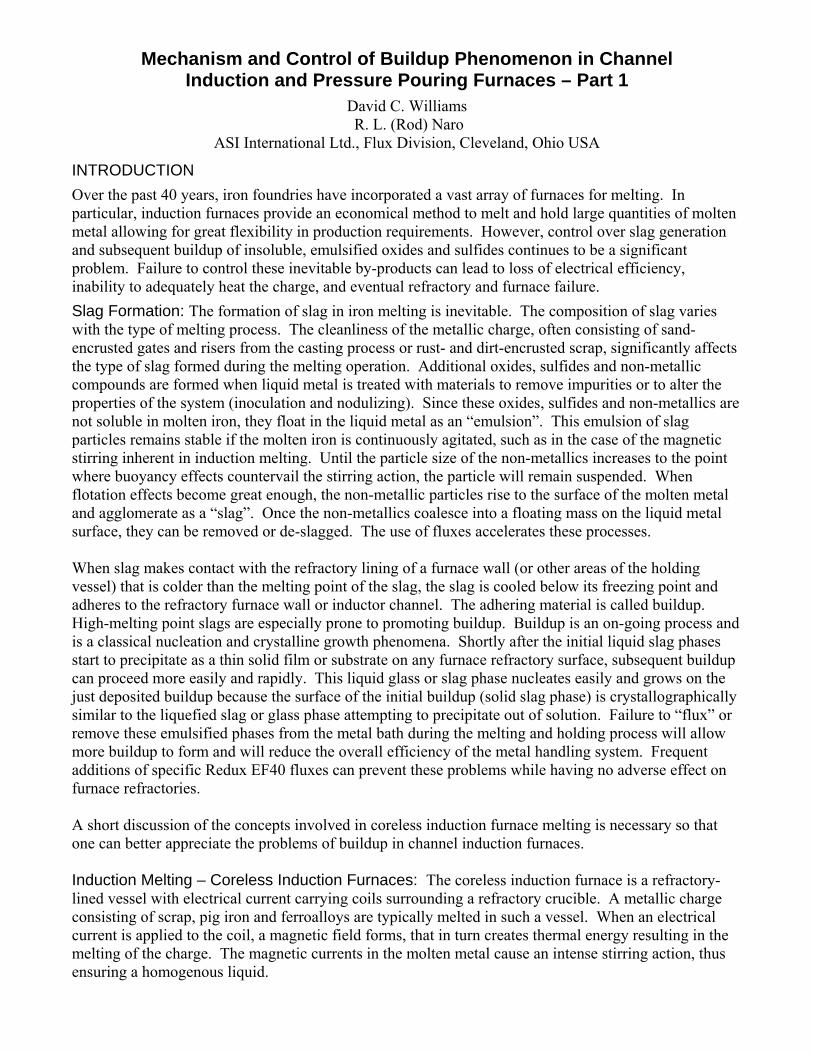
During the melting process, slag is generated from oxidation, dirt, sand and other impurities. Slag can also be generated from the scrap, erosion and wear of the refractory lining, oxidized ferroalloys and other sources. In a coreless induction furnace, slags normally deposit along the upper portion of the lining or crucible walls and above the heating coils. Figure 1 shows typical slag buildup in a coreless induction-melting furnace.
Figure 1: Typical slag buildup in a coreless induction furnace (gray shaded areas)
The hottest area of medium and high frequency coreless furnaces is at the mid-point of the power coil. All areas of slag deposit will be at a much lower temperature than those occurring at the center of the coil. Slag can also be deposited in areas midway down the crucible lining, where insufficient metal turbulence from magnetic stirring occurs.
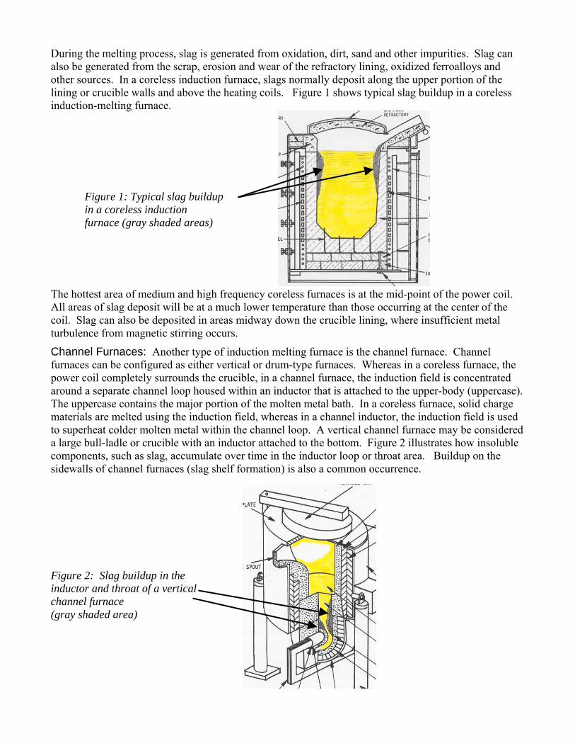
Channel Furnaces: Another type of induction melting furnace is the channel furnace. Channel furnaces can be configured as either vertical or drum-type furnaces. Whereas in a coreless furnace, the power coil completely surrounds the crucible, in a channel furnace, the induction field is concentrated around a separate channel loop housed within an inductor that is attached to the upper-body (uppercase). The uppercase contains the major portion of the molten metal bath. In a coreless furnace, solid charge materials are melted using the induction field, whereas in a channel inductor, the induction field is used to superheat colder molten metal within the channel loop. A vertical channel furnace may be considered a large bull-ladle or crucible with an inductor attached to the bottom. Figure 2 illustrates how insoluble components, such as slag, accumulate over time in the inductor loop or throat area. Buildup on the sidewalls of channel furnaces (slag shelf formation) is also a common occurrence.
Figure 2: Slag buildup in the inductor and throat of a vertical channel furnace (gray shaded area)
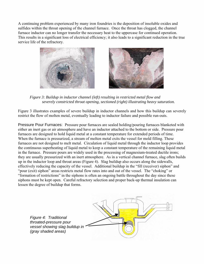
A continuing problem experienced by many iron foundries is the deposition of insoluble oxides and sulfides within the throat opening of the channel furnace. Once the throat has clogged, the channel furnace inductor can no longer transfer the necessary heat to the uppercase for continued operation. This results in a significant loss of electrical efficiency; it also leads to a significant reduction in the true service life of the refractory. Figure 3: Buildup in inductor channel (left) resulting in restricted metal flow and
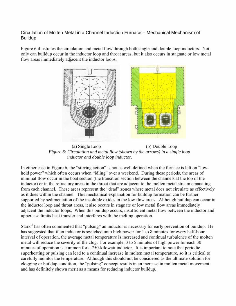
severely constricted throat opening, sectioned (right) illustrating heavy saturation. Figure 3 illustrates examples of severe buildup in inductor channels and how this buildup can severely restrict the flow of molten metal, eventually leading to inductor failure and possible run-outs. Pressure Pour Furnaces: Pressure pour furnaces are sealed holding/pouring furnaces blanketed with either an inert gas or air atmosphere and have an inductor attached to the bottom or side. Pressure pour furnaces are designed to hold liquid metal at a constant temperature for extended periods of time. When the furnace is pressurized, a stream of molten metal exits the vessel for mold filling. These furnaces are not designed to melt metal. Circulation of liquid metal through the inductor loop provides the continuous superheating of liquid metal to keep a constant temperature of the remaining liquid metal in the furnace. Pressure pours are widely used in the processing of magnesium-treated ductile irons; they are usually pressurized with an inert atmosphere. As in a vertical channel furnace, slag often builds up in the inductor loop and throat areas (Figure 4). Slag buildup also occurs along the sidewalls, effectively reducing the capacity of the vessel. Additional buildup in the “fill (receiver) siphon” and “pour (exit) siphon” areas restricts metal flow rates into and out of the vessel. The “choking” or “formation of restrictions” in the siphons is often an ongoing battle throughout the day since these siphons must be kept open. Careful refractory selection and proper back-up thermal insulation can lessen the degree of buildup that forms.
Figure 4: Traditional throated-pressure pour vessel showing slag buildup in (gray shaded areas)

When sufficient buildup forms, it will prevent adequate heating of the molten metal from the inductor. The inductor will have to be replaced because it can be extremely difficult to access and remove the buildup. Attempts to modify the furnace design with a throatless inductor (Figure 5) have been partially successful in eliminating buildup, but an aggressive, periodic cleaning procedure is still necessary.
Figure 5: Throatless pressure pour vessel showing slag buildup in (gray shaded areas)
Depressurizing a ductile iron pressure pour vessel and removing the top hatch for cleaning allows outside air to enter the vessel. This increases metal oxidation/resulfurization, and can aggravate buildup problems since oxygen is introduced into the vessel. The buildup must be removed by scraping from the sidewalls, inductor channel and throat. If the buildup is dense and well fused (hard), it is very difficult to remove. If the buildup is porous and soft, then it is possible that routine maintenance (scraping the sidewalls and rodding the inductor throat area with a metal tool or green wooden pole) can control accumulations. One major advantage of using the Redux EF40 flux when confronted with a dense, fused buildup, is that the flux alters the glass-like structure of the buildup that results in a “softening” of the buildup. Removal of the buildup is greatly simplified after fluxing and the time required for buildup removal can be reduced by up to 90%. When the buildup becomes severe, power factor readings of the inductor drop and the efficiency of the pressure pour is dramatically reduced.
SOURCES OF BUILDUP CONSTITUENTS Buildup represents a complex ceramic deposit of insoluble complex oxides and sulfides that occurs in the throat and in the inductors of the channel furnace. The presence of insoluble oxides within the melt occurs as a result of oxygen availability in the furnace. Insoluble sulfides within the melt can originate from charge materials as well as various contaminants such as machining fluids, dirt and by-products from desulfurization. Different theories surround the creation of the primary insoluble oxides and have been described by S. Singh1, R. Stark2 and others. Currently, the two theories which are the most plausible are (1) the diffusion of oxygen (air) through the porosity within the refractory and subsequent oxidation of the molten metal, and (2) residual insoluble oxides as by-products of the primary metal source or from the ferroalloys being used in the melt. A list of commonly recognized sources of primary oxides or sulfides is shown below:
• Oxidation of molten metal exposed to the atmosphere • Dirty, rusty scrap or charge materials, oxidized surfaces • Erosion of upstream refractories in the furnace uppercase or receiver • Contamination from minor elements used for inoculation or nodulizing • By-products from metal treatment operations such as desulfurization with calcium carbide • Residual contaminants from fluxing in the channel furnace uppercase
Circulation of Molten Metal in a Channel Induction Furnace – Mechanical Mechanism of Buildup Figure 6 illustrates the circulation and metal flow through both single and double loop inductors. Not only can buildup occur in the inductor loop and throat areas, but it also occurs in stagnate or low metal flow areas immediately adjacent the inductor loops. (a) Single Loop (b) Double Loop Figure 6: Circulation and metal flow (shown by the arrows) in a single loop inductor and double loop inductor. In either case in Figure 6, the “stirring action” is not as well defined when the furnace is left on “low-hold power” which often occurs when “idling” over a weekend. During these periods, the areas of minimal flow occur in the boat section (the transition section between the channels at the top of the inductor) or in the refractory areas in the throat that are adjacent to the molten metal stream emanating from each channel. These areas represent the “dead” zones where metal does not circulate as effectively as it does within the channel. This mechanical explanation for buildup formation can be further supported by sedimentation of the insoluble oxides in the low flow areas. Although buildup can occur in the inductor loop and throat areas, it also occurs in stagnate or low metal flow areas immediately adjacent the inductor loops. When this buildup occurs, insufficient metal flow between the inductor and uppercase limits heat transfer and interferes with the melting operation. Stark 3 has often commented that “pulsing” an inductor is necessary for early prevention of buildup. He has suggested that if an inductor is switched onto high power for 1 to 8 minutes for every half-hour interval of operation, the average metal temperature is increased and continual turbulence of the molten metal will reduce the severity of the clog. For example, 3 to 5 minutes of high power for each 30 minutes of operation is common for a 750-kilowatt inductor. It is important to note that periodic superheating or pulsing can lead to a continual increase in molten metal temperature, so it is critical to carefully monitor the temperature. Although this should not be considered as the ultimate solution for clogging or buildup condition, the “pulsing” concept results in an increase in molten metal movement and has definitely shown merit as a means for reducing inductor buildup.

Singh studied the mechanism of alumina buildup formation in pouring tubes and referred to three basic conditions that had to be satisfied: (1) particles have to come in contact with the refractory surface, (2) particles have to adhere to the refractory surface, and (3) particles have to adhere to each other so as to sinter and form a network. He explained the importance of metal velocity; especially in those areas close to a refractory surface where flow velocity is a function of the frictional force between the refractory surface and the molten metal. If the metal flow is kept at a high velocity and not allowed to remain in an idle or slow-moving state, the tendency for buildups to occur is usually reduced. Stirring action in an inductor is pronounced when the inductor is placed on high power. This “stirring action” refers to the actual metal flow through the inductor channels. Whether in a single loop or a double loop inductor, the molten metal is superheated within the inductor channels and enters the upper body through the throat. While “inductor pulsing” may provide temporary relief from channel clogging, in the long run, it does not remove buildup from the inductor loop or throat area. Often a furnace operator will attempt to insert a steel rod or green wooden pole into the throat area even though accessibility is often severely limited. When significant accumulations of buildup cannot be removed, the furnace is taken out of operation, the throat(s) are scraped clean and a newly lined inductor(s) is (are) installed. Normal inductor life may be as long as 18 months, however, if buildup occurs, the useful life may be reduced to only a few months and in some cases, a few weeks. THERMODYNAMIC EXPLANATION OF BUILDUP FORMATION While sedimentation of insoluble oxides in the low flow areas of the channel furnace is the main source of buildup, it is also important to consider the thermodynamic feasibility of complex mineralogical compound formation based on charge constituents and refractory composition. The order of precipitation of ceramic compounds (buildup formation) in the metal bath is a function of the compounds’ Gibbs free energy of formation, or ∆Gf
o. The larger the negative value of ∆Gfo, the
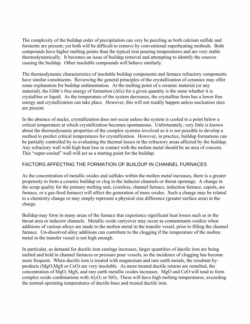
more likely a ceramic compound or slag will precipitate from the metal bath. However, what remains unknown is the likelihood that complex slag phases may precipitate simultaneously. Although no research has been done to prove this theory of simultaneous or preferential insoluble precipitation, researchers have observed such phenomena under the microscope. Researchers at the University of Missouri at Rolla used x-ray cathode-luminescence to depict the various ceramic phases present within buildup taken from channel furnaces and proved that the concentrations varied as the location within the buildup changed. The order of precipitation of ceramic compounds can be hypothesized by thermodynamic calculations but remains extremely difficult to determine due to complex chemistry of the systems involved. Table 1 lists the complex compounds, the mineral names, the melting points as well as the insoluble compounds’ free energy of formation4.
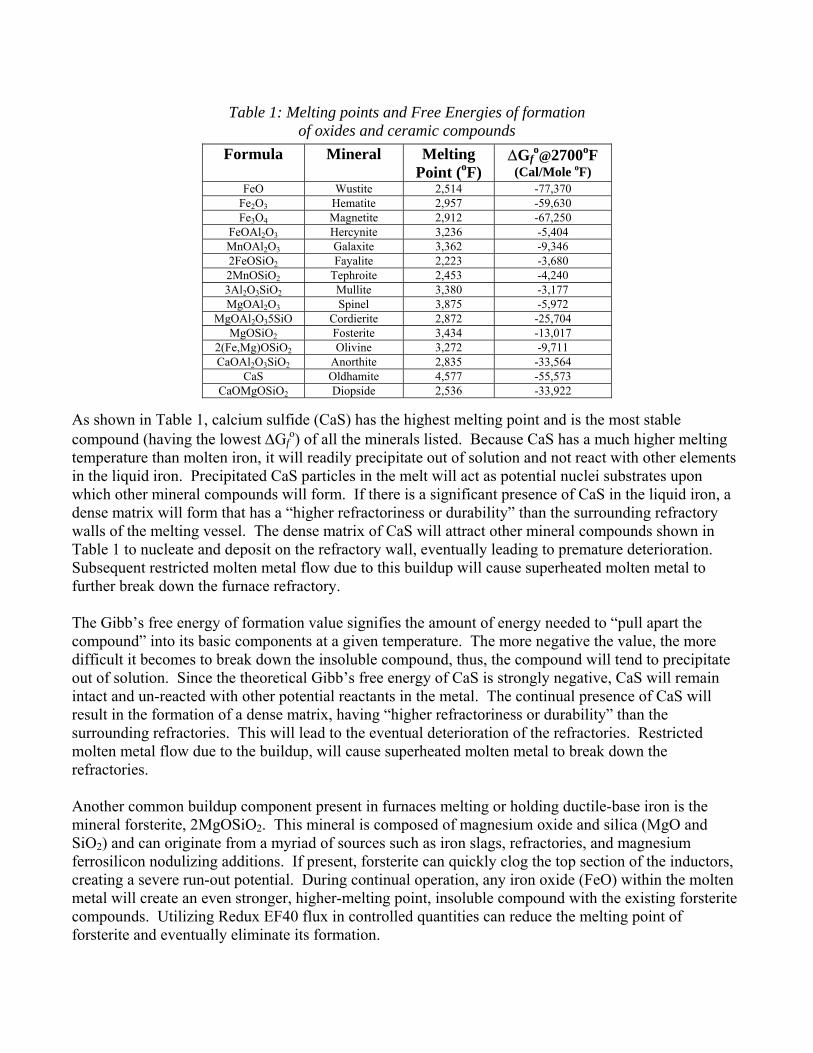
Table 1: Melting points and Free Energies of formation of oxides and ceramic compounds
Formula Mineral Melting Point (oF)
∆Gfo@2700oF
(Cal/Mole oF) FeO Wustite 2,514 -77,370
Fe2O3 Hematite 2,957 -59,630 Fe3O4 Magnetite 2,912 -67,250
FeOAl2O3 Hercynite 3,236 -5,404 MnOAl2O3 Galaxite 3,362 -9,346 2FeOSiO2 Fayalite 2,223 -3,680 2MnOSiO2 Tephroite 2,453 -4,240 3Al2O3SiO2 Mullite 3,380 -3,177 MgOAl2O3 Spinel 3,875 -5,972
MgOAl2O35SiO Cordierite 2,872 -25,704 MgOSiO2 Fosterite 3,434 -13,017
2(Fe,Mg)OSiO2 Olivine 3,272 -9,711 CaOAl2O3SiO2 Anorthite 2,835 -33,564
CaS Oldhamite 4,577 -55,573 CaOMgOSiO2 Diopside 2,536 -33,922
As shown in Table 1, calcium sulfide (CaS) has the highest melting point and is the most stable compound (having the lowest ∆Gf
o) of all the minerals listed. Because CaS has a much higher melting temperature than molten iron, it will readily precipitate out of solution and not react with other elements in the liquid iron. Precipitated CaS particles in the melt will act as potential nuclei substrates upon which other mineral compounds will form. If there is a significant presence of CaS in the liquid iron, a dense matrix will form that has a “higher refractoriness or durability” than the surrounding refractory walls of the melting vessel. The dense matrix of CaS will attract other mineral compounds shown in Table 1 to nucleate and deposit on the refractory wall, eventually leading to premature deterioration. Subsequent restricted molten metal flow due to this buildup will cause superheated molten metal to further break down the furnace refractory. The Gibb’s free energy of formation value signifies the amount of energy needed to “pull apart the compound” into its basic components at a given temperature. The more negative the value, the more difficult it becomes to break down the insoluble compound, thus, the compound will tend to precipitate out of solution. Since the theoretical Gibb’s free energy of CaS is strongly negative, CaS will remain intact and un-reacted with other potential reactants in the metal. The continual presence of CaS will result in the formation of a dense matrix, having “higher refractoriness or durability” than the surrounding refractories. This will lead to the eventual deterioration of the refractories. Restricted molten metal flow due to the buildup, will cause superheated molten metal to break down the refractories. Another common buildup component present in furnaces melting or holding ductile-base iron is the mineral forsterite, 2MgOSiO2. This mineral is composed of magnesium oxide and silica (MgO and SiO2) and can originate from a myriad of sources such as iron slags, refractories, and magnesium ferrosilicon nodulizing additions. If present, forsterite can quickly clog the top section of the inductors, creating a severe run-out potential. During continual operation, any iron oxide (FeO) within the molten metal will create an even stronger, higher-melting point, insoluble compound with the existing forsterite compounds. Utilizing Redux EF40 flux in controlled quantities can reduce the melting point of forsterite and eventually eliminate its formation.
The complexity of the buildup order of precipitation can very be puzzling as both calcium sulfide and forsterite are present; yet both will be difficult to remove by conventional superheating methods. Both compounds have higher melting points than the typical iron pouring temperatures and are very stable thermodynamically. It becomes an issue of buildup removal and attempting to identify the sources causing the buildup. Other insoluble compounds will behave similarly.
The thermodynamic characteristics of insoluble buildup components and furnace refractory components have similar constituents. Reviewing the general principles of the crystallization of ceramics may offer some explanation for buildup sedimentation. At the melting point of a ceramic material (or any material), the Gibb’s free energy of formation (∆Gf) for a given quantity is the same whether it is crystalline or liquid. As the temperature of the system decreases, the crystalline form has a lower free energy and crystallization can take place. However, this will not readily happen unless nucleation sites are present. In the absence of nuclei, crystallization does not occur unless the system is cooled to a point below a critical temperature at which crystallization becomes spontaneous. Unfortunately, very little is known about the thermodynamic properties of the complex systems involved so it is not possible to develop a method to predict critical temperatures for crystallization. However, in practice, buildup formations can be partially controlled by re-evaluating the thermal losses in the refractory areas affected by the buildup. Any refractory wall with high heat loss in contact with the molten metal should be an area of concern. This “super-cooled” wall will act as a starting point for the buildup. FACTORS AFFECTING THE FORMATION OF BUILDUP IN CHANNEL FURNACES As the concentration of metallic oxides and sulfides within the molten metal increases, there is a greater propensity to form a ceramic buildup or clog in the inductor channels or throat openings. A change in the scrap quality for the primary melting unit, (coreless, channel furnace, induction furnace, cupola, arc furnace, or a gas-fired furnace) will affect the generation of more oxides. Such a change may be related to a chemistry change or may simply represent a physical size difference (greater surface area) in the charge. Buildup may form in many areas of the furnace that experience significant heat losses such as in the throat area or inductor channels. Metallic oxide carryover may occur as contaminants oxidize when additions of various alloys are made to the molten metal in the transfer vessel, prior to filling the channel furnace. Un-dissolved alloy additions can contribute to the clogging if the temperature of the molten metal in the transfer vessel is not high enough. In particular, as demand for ductile iron castings increases, larger quantities of ductile iron are being melted and held in channel furnaces or pressure pour vessels, so the incidence of clogging has become more frequent. When ductile iron is treated with magnesium and rare earth metals, the resultant by-products (MgO,MgS or CeO) are very insoluble. As more treated ductile returns are remelted, the concentration of MgO, MgS, and rare earth metallic oxides increases. MgO and CeO will tend to form complex oxide combinations with Al2O3 or SiO2. These will have high melting temperatures, exceeding the normal operating temperatures of ductile-base and treated ductile iron.
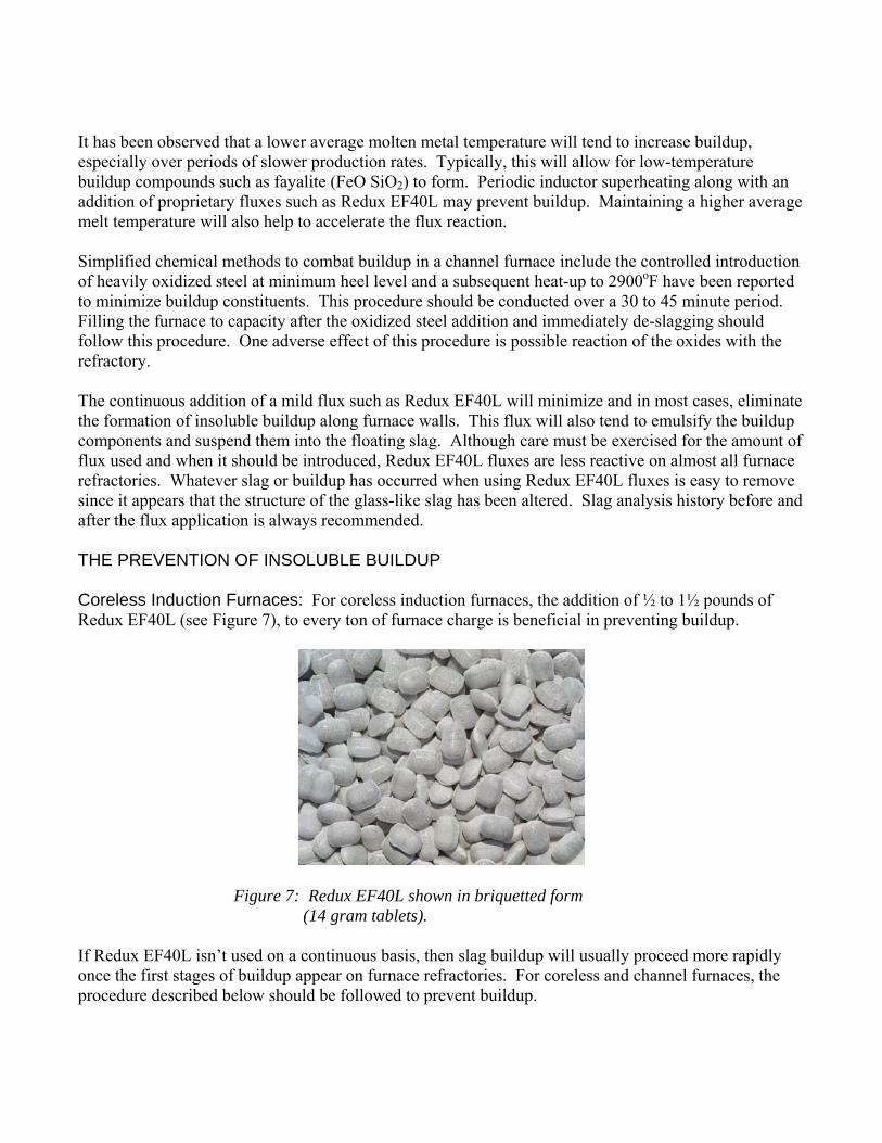
It has been observed that a lower average molten metal temperature will tend to increase buildup, especially over periods of slower production rates. Typically, this will allow for low-temperature buildup compounds such as fayalite (FeO SiO2) to form. Periodic inductor superheating along with an addition of proprietary fluxes such as Redux EF40L may prevent buildup. Maintaining a higher average melt temperature will also help to accelerate the flux reaction. Simplified chemical methods to combat buildup in a channel furnace include the controlled introduction of heavily oxidized steel at minimum heel level and a subsequent heat-up to 2900oF have been reported to minimize buildup constituents. This procedure should be conducted over a 30 to 45 minute period. Filling the furnace to capacity after the oxidized steel addition and immediately de-slagging should follow this procedure. One adverse effect of this procedure is possible reaction of the oxides with the refractory. The continuous addition of a mild flux such as Redux EF40L will minimize and in most cases, eliminate the formation of insoluble buildup along furnace walls. This flux will also tend to emulsify the buildup components and suspend them into the floating slag. Although care must be exercised for the amount of flux used and when it should be introduced, Redux EF40L fluxes are less reactive on almost all furnace refractories. Whatever slag or buildup has occurred when using Redux EF40L fluxes is easy to remove since it appears that the structure of the glass-like slag has been altered. Slag analysis history before and after the flux application is always recommended. THE PREVENTION OF INSOLUBLE BUILDUP Coreless Induction Furnaces: For coreless induction furnaces, the addition of ½ to 1½ pounds of Redux EF40L (see Figure 7), to every ton of furnace charge is beneficial in preventing buildup.
Figure 7: Redux EF40L shown in briquetted form (14 gram tablets).
If Redux EF40L isn’t used on a continuous basis, then slag buildup will usually proceed more rapidly once the first stages of buildup appear on furnace refractories. For coreless and channel furnaces, the procedure described below should be followed to prevent buildup.
1) During the back-charging sequence for either 60 cycle or medium frequency coreless furnace, add ½ to 1½ pounds of Redux EF40L per ton of metallic charge entering the furnace. Redux should not be added to an empty furnace; there should always be a molten metal bath remaining inside the furnace.
2) If a second back-charging is used, an additional ½ to 1½ pounds of Redux EF40L per ton of metallic charge should be added during the charging.
3) Once all of the solid charge has been melted, the slag from the top of the molten metal bath must be removed. It is important to not leave any residual slag inside the furnace after fluxing.
4) A representative slag sample before and after the Redux EF40 flux additions should be taken in order to quantify changes in slag composition.
Channel Holders and Pressure Pour Furnaces: For channel holders or pressure pour furnaces, the addition of ½ to 1½ pounds of Redux EF40L per ton of molten iron to every transfer ladle will assist in keeping those ladles clean. Redux fluxing or cleansing of the metal in the ladle and removal of various slag phases from the metal helps to prevent downstream buildup in holders and pressure pours. Redux EF40L users have reported significantly reduced furnace maintenance as less slag or buildup adheres to furnace walls. Additionally, fluxing will restore full furnace volume and lead to increased production. More importantly, the reduced quantity of buildup is accompanied by a “softer, less glass-like buildup” that is much more easily scrapped from the walls, without any subsequent damage to the refractory. There are two alternate treatment methods being used to combat insoluble buildup in channel furnace/ pressure pour uppercases, throat sections and inductor channels. These methods are described below. Uppercase Slag Ring Buildup: To combat a slag shelf in the upper case, a continuous Redux EF40L flux addition of ½ to 1½ pounds per ton of molten iron should be added through the cover of the uppercase or through the receiver\fill spout. For satisfactory results, it is important that the fill spout refractory be composed of a 65% alumina-mullite or higher grade refractory. Redux EF40L must be added to a clean, molten surface. Redux EF40L will be ineffective if it remains on top of a slag crust. The quantity of the Redux EF40L Flux will vary depending on the severity of the slag ring buildup in the uppercase. Flux addition rates as much as 4.0 pounds per ton of molten metal entering the furnace may be necessary along with timely slag removal as more slag will be created with the elimination of the slag ring or buildup. The length of time required for such uppercase fluxing will be dependent on the severity of the slag shelf, but may last for 3 to 4 days before the slag shelf disappears. It is extremely important to de- slag the furnace every day and remove all of the slag. Numerous foundries using Redux EF40L have reported that buildup removal after fluxing is much easier and faster. The time necessary to remove the stubborn buildup can be reduced by 75 to 90%. This is a direct result of altering the buildup structure and creating a softer buildup. In situations where there is a severe clogging of the inductor, two alternate methods are used to un-clog the throat section or inductor channels of a vertical channel holding/melting furnace as well as a pressure pouring channel furnace.

Severe inductor throat buildup: This procedure often requires 48 hours to implement. On the first day, the cover of the channel furnace or small “man-hole” cover of a pressure pour furnace is removed and slag is removed from the furnace. A clean molten metal surface is necessary for Redux EF40L to have maximum effect. Next, the molten iron level is lowered to a minimum heel, typically 4 to 15 tons depending on furnace size. An addition of 2 to pounds of Redux EF40L per ton is added to the molten heel after it has been heated to 2750oF (1510oC). The furnace cover should then be closed but not sealed and the inductor should be turned on full power for 3 to 4 hours, making sure that the molten iron temperature doesn’t exceed 2900oF (1600oC). It may be necessary to add another 2 to 3 pounds of Redux EF40 Flux per ton of molten iron, after 2 hours of superheating has occurred. The reactivity of the first addition may have been depleted after 2 hours. After the superheating period of the inductor has been completed, the molten iron should be cooled to normal holding temperatures. There will be more slag created which should be removed. However, depending on the foundry, it can be left inside for removal on the following day. A slag coagulant may be needed to assist in the removal of slag. A second application of flux may be required and a similar procedure followed the next day. However, Redux EF40L additions are often reduced to 1 to 1½ pounds per ton using the same superheating schedule. It is again important to remove all of the slag, and a slag coagulant may be needed to assist in the removal. In situations where the inductor cannot be revived because of severely clogged throats and/or inductor channels with the previously outlined procedure, then as a last alternative, plunging the flux into the throat with a specially designed plunging apparatus has restored such furnaces. An example of severe clogging which can lead to catastrophic inductor failure is shown in Figure 8.
Figure 8: Illustration of totally clogged inductor channel taken from a 10-ton channel furnace. The economic impact of buildup: Foundry X melts ductile base iron in a 35-ton vertical channel furnace utilizing a twin-loop water-cooled inductor. After installing a new inductor at the end of 2005, Foundry X started to experience severe buildup in the throat/ boat section of the inductor in January to mid-February 2006, just weeks after the inductor was replaced. From past experience, Foundry X knew that the downtime associated with a clogged inductor would be very costly. Typical downtime when the throat/inductor clogs is typically five days. During this period, Foundry X has to completely drain the furnace, reams out the throat opening and does a “hot inductor change”. Foundry X estimated that the total costs in downtime and lost production stemming from the “hot change” is roughly $90,000. Normally, the conductance ratio, (a measure of inductor electrical efficiency) at the beginning of a new refractory campaign is close to 100%. Typical conductance ratio history will see a gradual decline over a period of the first three to four weeks declining to 75 to 85% and will stabilize out while the power
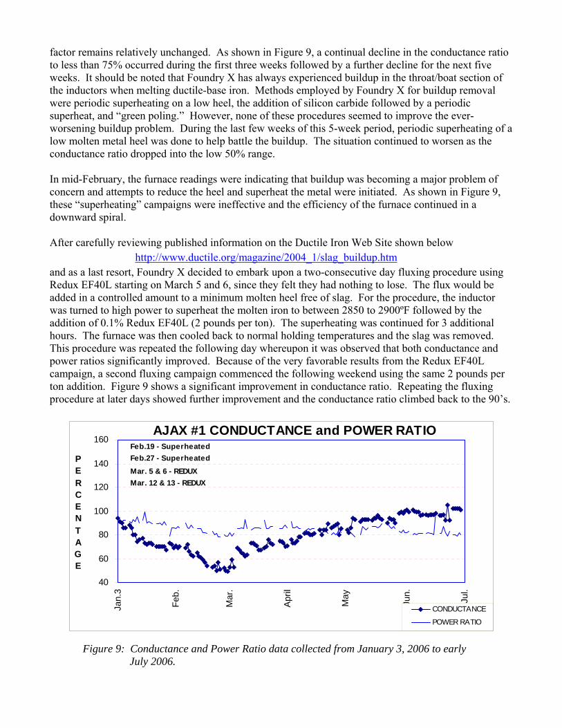
factor remains relatively unchanged. As shown in Figure 9, a continual decline in the conductance ratio to less than 75% occurred during the first three weeks followed by a further decline for the next five weeks. It should be noted that Foundry X has always experienced buildup in the throat/boat section of the inductors when melting ductile-base iron. Methods employed by Foundry X for buildup removal were periodic superheating on a low heel, the addition of silicon carbide followed by a periodic superheat, and “green poling.” However, none of these procedures seemed to improve the ever-worsening buildup problem. During the last few weeks of this 5-week period, periodic superheating of a low molten metal heel was done to help battle the buildup. The situation continued to worsen as the conductance ratio dropped into the low 50% range. In mid-February, the furnace readings were indicating that buildup was becoming a major problem of concern and attempts to reduce the heel and superheat the metal were initiated. As shown in Figure 9, these “superheating” campaigns were ineffective and the efficiency of the furnace continued in a downward spiral. After carefully reviewing published information on the Ductile Iron Web Site shown below
http://www.ductile.org/magazine/2004_1/slag_buildup.htm
and as a last resort, Foundry X decided to embark upon a two-consecutive day fluxing procedure using Redux EF40L starting on March 5 and 6, since they felt they had nothing to lose. The flux would be added in a controlled amount to a minimum molten heel free of slag. For the procedure, the inductor was turned to high power to superheat the molten iron to between 2850 to 2900ºF followed by the addition of 0.1% Redux EF40L (2 pounds per ton). The superheating was continued for 3 additional hours. The furnace was then cooled back to normal holding temperatures and the slag was removed. This procedure was repeated the following day whereupon it was observed that both conductance and power ratios significantly improved. Because of the very favorable results from the Redux EF40L campaign, a second fluxing campaign commenced the following weekend using the same 2 pounds per ton addition. Figure 9 shows a significant improvement in conductance ratio. Repeating the fluxing procedure at later days showed further improvement and the conductance ratio climbed back to the 90’s.
40
60
80
100
120
140
160
Jan.
3
Feb.
Mar
.
Apr
il
May
Jun.
Jul.
PERCENTAGE
CONDUCTANCE
POWER RATIO
AJAX #1 CONDUCTANCE and POWER RATIOFeb.19 - SuperheatedFeb.27 - SuperheatedMar. 5 & 6 - REDUX Mar. 12 & 13 - REDUX
Figure 9: Conductance and Power Ratio data collected from January 3, 2006 to early July 2006.
Foundry X continues to utilize Redux EF40L in their operation and is considering a maintenance addition of Redux EF40L with each furnace charge to insure that future inductor clogging is eliminated. The nominal costs associated with an addition of Redux EF40L to each charge is offset by improved furnace efficiency and elimination of costly downtime from inductor clogging. Ductile iron foundries utilizing channel or pressure pour furnaces or both, need to examine the cost benefits of adding fluxes with their charge as a preventative measure to guard against buildup. Foundries utilizing fluxes in their melting operation have found that the costs associated with adding flux to each charge is insignificant compared to downtime for replacement of a terminally clogged inductors or severe sidewall buildup. Many of these foundries have found that they have been able to greatly extend refractory life with the addition of fluxes to their charges. Lastly, concerns regarding the addition of ferrous fluxes to foundry melting and holding units have largely proved to be inaccurate regarding potential refractory attack. Conclusions Buildup is a complex molten metal issue plaguing many foundries today. In ductile iron foundries, buildup is responsible for the majority of downtime at the various pouring stations. Insoluble buildup can be a direct result of tramp oxides/sulfides within the charge. Other buildup components can be traced back to residuals in alloy additions as well as chemical reactions against the refractories within the furnaces or transfer vessels. Yet other sources may be the result of an oxidizing atmosphere or residual coatings coming in with the charge. This paper offers some important criteria for developing a plan of attack to combat the buildup where it has developed and how to correct it utilizing a preventative maintenance plan of adding a mild fluxing agent, Redux EF40L, to each charge. Methods that have been successfully employed to reduce buildup in channel furnace upper cases and methods to un-clog severely restricted inductor throats are discussed. The paper also discusses the thermal conditions of the refractory walls that are prone to the buildup deposition. References: 1. Singh, S.N., Mechanism of Alumina Buildup in Tundish Nozzles During Continuous Casting of Aluminum-killed steels, Metallurgical Transactions, Volume 5, October 1974 pgs 2165 - 2178 2. Stark, Ronald A., Buildup of Nonmetallic Particles on Refractories of Induction Furnaces, Center for Materials Production /EPRI, February 1990, CMP Report No. 90-3, Sections 1 to 5. 3. Stark, Ronald A., Private Communication 4. AFS 8D Channel Furnace Sub-committee and University of Rolla, Missouri 1990.
Acknowledgements: The authors would like to thank Mr. Pete Satre, Allied Mineral Products, Inc. as well as Mr. Greg Lemley and Brian Naro, ASI International, Ltd. for reviewing the original manuscript and their constructive comments.