Embed Size (px)
Citation preview
This article was downloaded by:[Dip Ing Aeronautica Spaziale]On: 8 February 2008Access Details: [subscription number 771006676]Publisher: Taylor & FrancisInforma Ltd Registered in England and Wales Registered Number: 1072954Registered office: Mortimer House, 37-41 Mortimer Street, London W1T 3JH, UK
Mechanics of Advanced Materialsand StructuresPublication details, including instructions for authors and subscription information:http://www.informaworld.com/smpp/title~content=t713773278
ZIGZAG AND INTERLAMINAR EQUILIBRIA EFFECTSIN LARGE-DEFLECTION AND POSTBUCKLINGANALYSIS OF MULTILAYERED PLATESE. Carrera a; B. Kröplin aa Aerospace Department, Institute for Statics and Dynamics, University of Stuttgart,Stuttgart, Germany
Online Publication Date: 01 January 1997To cite this Article: Carrera, E. and Kröplin, B. (1997) 'ZIGZAG ANDINTERLAMINAR EQUILIBRIA EFFECTS IN LARGE-DEFLECTION ANDPOSTBUCKLING ANALYSIS OF MULTILAYERED PLATES', Mechanics of
Advanced Materials and Structures, 4:1, 69 - 94To link to this article: DOI: 10.1080/10759419708945875URL: http://dx.doi.org/10.1080/10759419708945875
PLEASE SCROLL DOWN FOR ARTICLE
Full terms and conditions of use: http://www.informaworld.com/terms-and-conditions-of-access.pdf
This article maybe used for research, teaching and private study purposes. Any substantial or systematic reproduction,re-distribution, re-selling, loan or sub-licensing, systematic supply or distribution in any form to anyone is expresslyforbidden.
The publisher does not give any warranty express or implied or make any representation that the contents will becomplete or accurate or up to date. The accuracy of any instructions, formulae and drug doses should beindependently verified with primary sources. The publisher shall not be liable for any loss, actions, claims, proceedings,demand or costs or damages whatsoever or howsoever caused arising directly or indirectly in connection with orarising out of the use of this material.

Dow
nloa
ded
By:
[Dip
Ing
Aer
onau
tica
Spa
zial
e] A
t: 13
:37
8 Fe
brua
ry 2
008
ZIGZAG AND INTERLAMINAR EQUILIBRIA EFFECTS IN LARGE-DEFLECTION AND POSTBUCKI-ING ANALYSIS OF MULTllAYERED PLATES
E. Carrm and B. fioplin Institute f i j r Statics and Dynamics, Aerospace Department, University of Stuttgart. Stuttgart, Germany
Concerning! hlgher-order shear d e f o d n theories (HSDT) for composite pkJes, this article presents a numerical investigation on local chamctericlics (disbibulidn along the phte thickness of i n - p h e displacement, in-plane nods t ress , and lmnsverse shear sbess components) in the hrge-dcfiction and postbuckling fields. The von K6nn6n theory in conjunction with a recent mixed two-dimensional ntodel, elsewhere denokd by the acronym RMZC (Rdsmer-Mindlin zigzag continuity) is employed The RMZC modei assumes &o independent fiehis along the plate thickness for displacements and fmnsverse shear stresses, respectively; the displacement model describes the so-called zigzag form for the in-plane components, whiLe the stress field fulfiLF intertrminar equilibria. Standard displacement f o m & t i o n is e Jomed by employing v -dy consistent constilutive equafioh between stress and dispLacement u n k ~ wns. Firrirt-element-type ~ p m x i t n d o n s are infroduced on - - - - the plate domain, leading to goveminng equations in the form of rr nonlinear system of algebraic eq&ns. This is solved thmugh application of the Newton-Rqhson method accounting for arc-length stmtegies. Explicit fonns of the linear and nonlinear resulting &es are quoted in appendixes. The numerical investigolion and discussion concern largedefrecction and postbuckling analysis of symmetrically Inminute square thiciklthin plates subje,cted lo simply suppo fledand clamped boun&ty conditions. Results of the RMZC model are compared with those rekrtcd to CLT ckrssical lamination theory (CLT) and first shear &formation theory (FSDT). It luu been confLnred thd the imporiunce of effects related to &he RMZC model are more evident when local clramcreristics are described Furthermore, it h a been found Uual such effects become more s ign imnt when large deficctions nr well as postbuckled equilibrium slates of thick plates are considere4 whik for the thin-plate analyses, FSDT and RMZC have furnished very close results.
Because of their high stiffnessfstrength-to-weight ratio, composite material systems are preferred in aerospace: applications, and this has resulted in numerous studies regarding their response. However,. these advanced composite structures are characterized by weak rigidities in transverse shear. Moreover, current metal aircraft design practices allow skin of some structural components (e-g., fuselage, wing, and stabilizer panels) to buckle at
Received 23 October 1995; accepted 8 April 1996. E. Camra is visiting under GKKS grant; his permanent address is DIAS, Politecnico di Torino, Tor-
ino. Italy. Address correspondence to Dr. Erasmo Canera, Dipartimento di Ingegneria Acronautica E Spaziale.
Politecnico di Torino, Corso Duca degli Abruzti. 24-10124 Torino, Italy. E-mail: [email protected]
Mechanics of Composite Materfals and Structures, 4:69-96,1997 Copyright 0 1997 lhylor & Francis
1075-9417/97 $12.00 + .00

Dow
nloa
ded
By:
[Dip
Ing
Aer
onau
tica
Spa
zial
e] A
t: 13
:37
8 Fe
brua
ry 2
008
70 E. CARRERA AND B. KROPLIN
load levels below the designed ultimate loading condition. In fact, these structural elements are designed to have a postbuckling strength; evidently, a better understanding of the large-deflection and postbuckling behavior of composite panels constitutes an essential requirement toward a rational employment of their strength. Because of the geometry of laminated structural components, two-dimensional approaches have been used extensively to trace their response. The classical Kirchhoff plate theory (classical lamination theory, CLT) has been revealed to have limits when applied to thick panels with high orthotropic ratio [I]. Shear deformation theories of the Reissner-Mindlin type first shear deformation theories (FSDT), even though they are quite acceptable for studying global response of high-shear. deformable, thick composite structures, are not adequate for forecasting local stress-strain characteristics. In fact, for some representative problems, early exact three- dimensional solutions 12.31 have shown the failure of FSDT both to fulfil the interlaminar transverse shear stresses continuity at each interface and to describe the so-called zigzag form [2-41 of the displacement fields along the laminate thickness. Moreover, experiments and practice have shown the fundamental role played by interlaminar stresses in failure mechanisms such as delamination between two adjacent layers [S, 61. Therefore. many theories that improve FSDT have been proposed in the last three decades. Those preserving the two-dimensional advantage, i.e., the number of the unhowns is independent from the number of the layers, have been named equivalenr single-layer theories; others, which consider each layer as a single plate, increasing very much the number of the unknowns, are known as layer-wise rheories. Exhaustive overviews on this topic can be found in [7-111. Here the interest is focused on single-layer-type theories. These theories are usually called higher-order shear deformation theories (HSDT). Among these models, the authors mention the very elegant and efficient, but rarely cited, formulation presented by Ren [12].
Anisotropy. higher-order modeling, and geometric nonlinearities greatly increase the difficulties of finding numerical solutions [13-151. Because of these difficulties, very few results are available concerning HSDT effects in large deflection fields: see [16, 171. Such results mainly concern global characteristics, such as global deflections [18-231 or flutter response [24]. Very seldom they are related to local distributions along the plate thichess of stress and displacement components 191. On the other hand, the progress made by computational mechanics in the last two decades very much helps to subjugate the difficult- ies mentioned. The finite-element formulation in particular provides a convenient solution method for such laminated composites having complex geometries, arbitrary loadings, as well as support conditions and layouts [25-301. Most of the proposed finite- element- accounting HSDT formulations are C1-continuity formulated (in the sense that derivatives of the unknowns are used as degrees of freedom). Nevertheless, plate theories with C1 continuity, especially when applied to nonlinear problems, are computationally weak [25, 261. Numerically efficient C0 continuity (in the sense that derivatives of the unknowns are not present as degrees of freedom), formulated plate elements are discussed in [lo, 21, 31, 321. Putcha and Reddy [21] pIESe~ed C0 continuity by developing a mixed finite- element consisting of 11 degrees of freedom (three displacements, two rotations, and six moment resultants); this model satisfies top and bottom faces of the plate conditions and does not require a shear-correction factor. This element was evaluated in the nonlinear analysis of global characteristics of laminated anisotropic rectangular plates subjected to transverse loads. Pandya and Kant [31] presented C0 finite elements at the displacements formulated; improvements of the FSDT description were obtained by adding quadratic and cubic terms in the displacement model. Extension to large-amplitude, free vibrations of
Dow
nloa
ded
By:
[Dip
Ing
Aer
onau
tica
Spa
zial
e] A
t: 13
:37
8 Fe
brua
ry 2
008
ZIGZAG AND lTWERLAMINAR EQUILlBRlA EFFECTS 71
laminated plates was presented in [33]. To the best of the authors' knowledge, no results are available from the open literature concerning local descriptions of zigzag and interlhnar equilibria effects in nonlinear analysis. This article contributes to the understanding of higher-order shear deformation effects on both global and local characteristics of multilay- ered plates in large-deflection and postbuckling fields. The mixed two-dimensional mechan- ical model proposed in [34,35], is employed. This was denoted in [32] by the acronym RMZC (Reissner-Mindlin zigzag continuity). It was seen as the extension of the Reissner- Mindlin model for mullilayered plate analysis. It assumes two independent fields along the plate thickness for the displacements and transverse shear stresses, respectively; the displacement model describes the so-called zigzag form for the in-plane components, while the stress field fulfils interlaminar equilibria. The standard displacement formulation is enforced by employing variationally consistent constitutive equations between stress and displacement unknowns as in [lo, 321. With respect to [32], the model in this work is extended to von K h h - t y p e geometric nonlinearities. Efficient finite-element approxima- tions are developed in the numerical investigations. The governing nonlinear system of algebraic equations is then solved by employing the Newton-Raphson linearization account- ing arc-length-type straregies. Explicit forms of the linear and nonlinear finite-element equation in matrix form are given in appendixes. Numerical results first recall the perfor- mance of the mechanical models in linear analysis, then both large deflections and postbuck- ling of symmetrically lanunated plates, subjected to simply supported and clamped boundary conditions, are investigated. Solutions and discussion are given with respect to both global response and local char.wteristics. Thick and thin plates are studied. Shear deformation, zigzag, and interlaminar equilibria effects are ma& evident by comparing RMZC, FSDT. and CLT results for each of the analyses conducted.
MECHANICS OF THE ASSUMED TWO-DIMENSIONAL MODEL
Preliminary
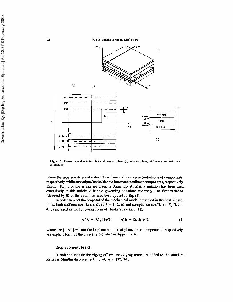
The geometxy, notation, and coordinate system of the laminated plates of N, layers are shown in Figure 1. The integer k ¬es the layer number, starting from the top plate. The letters x and y denote the plate middle surface coordinates. fl is the x, y plate domain. The lamina are assumed to be homogeneous and orthotropic, and the material is supposed to work in a linear elastic field. For convenience, several reference coordinates are intro- duced along the plate thickness. z is the global coordinate along the plate thickness h. 4 (zk = z - zok. tar denoting the distance of the middle surface of the k layer from the x-y plane) denotes the local coordinate along the k-layer thickness hk. 5 = 22th and tk = 2zJhk denote the nondi~nensional global plate coordinate and local k-layer coordinate, respectively. Ak denotes the zk domain at the k layer and Ok the orientation with respect to the global x axis. Stress, strain, and displacement components along the global triorthogonal Cartesian system are denoted by subscripts 1, 2, 3 or x, y, z.
According to the von K h h large-deflection approximations, the strain components eij ( i , j = 1, 3; as in the Reissner-Mindlin model, normal strain components g3 are discarded) are related to the displacement components ui (i = 1, 3) as in the following:
Dow
nloa
ded
By:
[Dip
Ing
Aer
onau
tica
Spa
zial
e] A
t: 13
:37
8 Fe
brua
ry 2
008
E. CARRERA AND B. KROPLIN
Rgure 1. Geometry and notation: (a) multilayend plate; (b) notation along thickness coordinate; (c) k interface.
where the superscripts p and n denote in-plane and transverse (out-of-plane) components, respectively, while subscripts I and nl denote linear and nonlinear components, respectively. Explicit forms of the arrays are given in Appendix A. Matrix notation has been used extensively in this article to handle governing equations concisely. The first variation (denoted by 6) of the strain has also been quoted in Eq. (1).
In order to meet the proposal of the mechanical model presented in the next subsec- tions, both stiffness coefficient Cij (i, j = 1. 2, 6) and compliance coefficient Sii (i , j = 4, 5) are used in the following form of Hooke's law (see [I]),
where ( u p ) and {on) are the in-plane and out-of-plane stress components, respectively. An explicit form of the arrays is provided in Appendix A.
Displacement Field
In order to include the zigzag effects, two zigzag terms are added to the standard Reissner-Mindlin displacement model, as in [32, 341,

Dow
nloa
ded
By:
[Dip
Ing
Aer
onau
tica
Spa
zial
e] A
t: 13
:37
8 Fe
brua
ry 2
008
ZIGZIG AND INTERLAMINAR EQUILlBRlA EFFECTS 73
Up, a, and U! are the displacement components of a point on the reference surface 42 of the plate. UI and U: denote the rotations of the normal to the reference surface in the planes x-z and y-z, respectively. (- I ) ~ D , and Ck (- l)&Dz are the zigzag terms; these terms have the goal of reproducing the discontinuity on the first derivative along z at each layer interface observed in (21; see Figure 2a. The matrices introduced are written explicitly in Appendix ~ 4 .
Transverse Stress Field
The order of the :: expansion for the transverse stresses (on) is established to be quadratic at each k layer; see Figure 26. The assumed transverse stress model is (see [32.341)
Note that the model of Eq. (4) uses six k-dependent functions: the two stress resultants Ri3(x. y) = .fA& (x, y) dz, R!J (x, y) = sAL IJ$~ (x, y) dz and the four interface transverse stress values at the top :md the bottom of the k layer (denoted by a$, a$ and ug, og, respectively). Furthermclre.
Figure 2 Assumed models along the thickness coordinate: (a) In-plane displacements u, and u,; (b) transverse shear stresses of, and nu.

Dow
nloa
ded
By:
[Dip
Ing
Aer
onau
tica
Spa
zial
e] A
t: 13
:37
8 Fe
brua
ry 2
008
74 E. CARRERA AND B. K R ~ P L I N
If the equilibria conditions at each interface have to be fulfilled, then the following set of boundary conditions must be linked to the stress unknowns:
(a) Layer interfaces (6) toplbottom plate
The overbar denotes imposed transverse shear stresses. Thus, the assumed transverse stress model is capable of fulfilling both interlaminar equilibria and toplbottom plate- imposed transverse stress conditions.
Constitutive Equations for the Transverse Stress Unknowns
In order to eliminate the stress unknowns {&) reference is made to the method described in [lo, 321. where some of the original ideas presented in [36], aie used. A short description follows. First the following equality is written between transverse shear strains coming from Eq. (1) (subscript G as geometric) and those from Eq. (2) (subscript H as Hooke),
By multiplying Eq. (6) with the introduced stress model EQ. (4) (subscript M as model, in order to distinguish related stresses from those coming from Hooke's law), then the following weak-form equations can be written for each layer:
where superscript T denotes transposition of arrays. From these, the constitutive equations of the k lamina for the transverse stresses can be obtained in a form consistent with the assumed models in Eqs. (3) and (4). In fact, when substituting these models, Eq. (7) leads to the following set of variational equations:
k u - k k = 0 k = 1, Nf (8)
where
The matrix [&Ik is symmetric and nonsingular, while [Hulk is singular and nonsymmetric; these matrices are written explicitly in Appendix A. In order to impose the boundary conditions [Eqs. (5)], it is convenient to obtain the constitutive equations at a multilayered level. This is shown in detail in [32]. As a result, the following constitutive equations are written for each layer between introduced stress and displacement unknowns:

Dow
nloa
ded
By:
[Dip
Ing
Aer
onau
tica
Spa
zial
e] A
t: 13
:37
8 Fe
brua
ry 2
008
Z1GZA.G AND INTERLAMINAR EQUILIBRIA EFFECT?3 75
The matrix [Cult is also given in Appendix A. {F*} is a load vector coming from the imposed transverse shear stress in Eq. (5). In the following it is assumed that (P*} = 0.
DESCRIPTION OF THE COMPUTATIONAL MODEL
Finite-Element C~pproximation on
In the previous section an approximated model along the thickness coordinate was assumed for the unknown functions (u) and {a"). In order to obtain numerical solutions for various geometric mechanical boundary conditions and laminated layouts, further approximations must be introduced on the plate domain In this article, reference is made to the finite-element method (FEM). In such a context is subdivided into a certain number of elements. Then assumptions are made about the behavior of the unknown vector (&I in each element domain. As the 2D model in Eq. (3) has been formulated with d continuity, an isoparametric description can be referred to. For example, for the unknown UT one has
where Ni (6, q) are Nn shape functions (Nn is the number of nodes) defined in the natural plane 5, q, see [25]. In tlie isoparametric formulation the same shape functions are used for the different unknowtrs, so the unknown vector is written as
[Nl is a diagonal matrix whose elements are the shape functions Ni (5, q). while
is the vector of the 7 X 1V, unknowns at element level.
Equilibrium Equations
Let us consider a multilayered plate of volume V subjected to external mechanical loads. In the static case tl~e principle of virtual displacement states that
where 84 is the virtual variation of internal work and SL, is the virtual variation of the work done by the applied external loads. The variation of the internal work can be split into in-plane and out-of-plane contributions:

Dow
nloa
ded
By:
[Dip
Ing
Aer
onau
tica
Spa
zial
e] A
t: 13
:37
8 Fe
brua
ry 2
008
76 E. CARRERA AND B. KR~PLIN
The in-plane or bending contribution has been split into a linear and a nonlinear part. With the adopted notations and approximations, introduced step by step, one has
where [Kfl is the stiffness matrix relating to the linear contribution of the bending deformations. In the same way, the shear contribution reads:
where [Kn] is the shear contribution to the stiffness matrix. Global non-linear stiffness matrices are obtained in a symmetric form by referring to the method proposed in references [37, 381. According to that method, the variation of the virtual work related to the non- linear deformations is written as

Dow
nloa
ded
By:
[Dip
Ing
Aer
onau
tica
Spa
zial
e] A
t: 13
:37
8 Fe
brua
ry 2
008
ZICZALC AND INTERLAMINAR EQUILIBRIA EFFEClS 77
where the initial stress or geometric stiffness matrix [KE,] related to the linear part of the in-plane stresses has been introduced. Except for the initial stress matrix, the factor 3 underlines that the nonlinear part of the secant matrix can be obtained as one-half of the corresponding nonlinear part of the tangent matrix (see next subsection). For completeness, all the stiffness matrices are written expticitly in Appendix B.
The variation of external work given by distributed pressure andlor point loads can be written as
where {P) is the load vector equivalent in the finite-element sense to the applied loads. Finally, from Eq. (13), the approximate form of equilibrium reads:
where the secant stiffness matrix is
The above equations have been written at element level; they take the same form when written at plate level. In this case, element arrays are assembled with the usual FEM technique.
Newton-Raphson Method Accounting Arc-Length Strategies
The nonlinear system of algebraic equations, Eq. (19), gives the FEM model of the physical problem. A total Lagrangian description can be referred and a standard solution scheme can be obtained through the following straightforward application of the Newton- Raphson method betwee11 the initial equilibrated state i and the unknown state i + 1 (in the neighborhood of i ) (see [26, 271).
A denotes finite variations between the two states i and i + 1. The applied load vector (PI is supposed to be displacement-independent; furthermore, (P) increases proportionally by means of the load parameter A from the initial reference configurations (PEf). {+J = [Ks {QS)] [a) - Ai(Pnf) is the residual nodal vector of the nodal forces (unbal- anced nodal forces vector). A{QY) is the increment of the displacement vector, while Ah is the increment of the load parameter. [KT] is the tangent stiffness matrix. This matrix is related to the second variation of the internal work,
Dow
nloa
ded
By:
[Dip
Ing
Aer
onau
tica
Spa
zial
e] A
t: 13
:37
8 Fe
brua
ry 2
008
78
and
EL CARRERA AND B. KR~PLIN
Then
the same matrices as in Eq.(19) have been found. Note that the initial stress matrix [Ks] now refers.to both linear and nonlinear parts of the in-plane stresses {aP}: Since the load level h is treated as a variable, an extra governing equation is required, and this is given by a constraint relationship of the form c((Aq), Ah) = 0. Finally, the complete system follows,
Several forms of the constraint equation have been proposed by the FEM literature. Reviews can be found in References [26, 391.
NUMERICAL RESULTS
Data Descriptions
Square plates of length a and thickness h (the value h = 1 is assumed everywhere), symmetrically laminated, are considered in the following numerical investigations. Consis- tent units are intended for both mechanical and geometric parameters. Cross-ply O0/9O0I 0" and angle-ply 45O/-45O145" are analyzed; each layer has W3 thickness. The mechanical properties of the lamina used, with usual notations, [40] are: El = 25, E, = 1, Gh.= 0.5, G,, = 0.2, vl, = v, = 0.25. Simply supported SSSS (@ = 0, x = 0, a and y = 0, a) and clamped CCCC (@ = 0, V! = 0, Dl = 0 in x = 0, a and @ = 0, I/: = 0 , 4 = 0 in y = 0;a) edges are treated. CLT results are obtained through application of a penalty technique to the shear correction factor; the value x = 1@ is used. FSDT results refer to the value x = 516. The finite-element investigations refer to regular meshes of parabolic Lagrangian, nine-node elements Q9 (see [32]).
Performances of RMZC Model in Linear Analysis and Comparison with 3D and Other HSDT Solutions
Assessment of RMZC finite elements in the linear analysis with respect to numerical performances has been provided elsewhere [32]. Some results related to the main character- istics of the RMZC model in linear analysis of multilayered plates are briefly reviewed. The sample problem analyzed by Pagano [2] is considered. It consists of a square plate, simply supported, three-layered, cross-ply, subjected to transverse pressure p,. One quarter

Dow
nloa
ded
By:
[Dip
Ing
Aer
onau
tica
Spa
zial
e] A
t: 13
:37
8 Fe
brua
ry 2
008
ZIGZAG AND INTERLAMINAR EQUILIBRIA EFFECTS 79
a b l e 1. Comparison b e e n present analysis and other results from literature; E3 values arr compared - - - - - -
Present References
FSDT CLT HSDT HSDT FSDT
RMZC RhiZ X ' s x-+ld 31 4 1 3 1
7.587 8.250 7.363 0.678 - - - 2.886 3.086 2.587 0.67 1 2.877 2.909 2.656 1.091 1.147 1.013 0.670 1.097 1.090 1.02 1 0.687 0.690 0.684 0.670 - - - 0.674 0.670 0.673 0.670 0.67 1 0.67 1 0.670
of the plate is analyzed with a 2 X 2 mesh. Table 1 refers to a constant distribution of normal pressure p,. The maximum transverse deflection ii3 = u,(lOO Ejh3/pza3), located at the plate center, for different values of the thickness parameter d h , is compared with available results. The following can be seen: CLT results are d h independent. i.e.. the penalty technique used remains very efficient. RMZC analysis leads to results whose accuracy can be compared with that obtained by other authors. The RMZ analysis is related in the particular case in which interlaminar equilibria Eq. (5) are not imposed on RMZC. By comparing l W C with RMZ results, one notices that the importance of the interlaminar equilibria increases very much for thick plates. Figure 3 compares RMZC with two other higher-ortier models, RH and RF, given in [42], and to the three-dimensional solution 3D given in [2] . The distribution of both the in-plane displacements ii, =
Figure 3. co'kparison bet wee^ RMZC and other results in linear analysis: (a) distribution of El diplacements along the z coordinate; (b) distribution of along the z coordinate. Data: bisinosoidal distribution of pressure, QP clement with 2 X 2 mesh. alh = 4. Suffix "-Eq" denotes results obtained by integration of 3D indefinite equilibrium equations.

Dow
nloa
ded
By:
[Dip
Ing
Aer
onau
tica
Spa
zial
e] A
t: 13
:37
8 Fe
brua
ry 2
008
80 E. CARRERA AND B. K R ~ P L I N
~ ~ ( ~ 1 ' 2 , 0 , z)(E, h21p$) and transverse shear stress E, = u,(a/2, 0, z)(Wpp) along the thickness of the same plate considered in Table 1 is plotted for the value d h = 4 of the thickness parameter. A bisinusoidal distribution of the transverse pressure of the p, ampli- tude is applied at the top surface of the plate. Figure 3a shows the capability of the RMZC element, with respect to both CLT and FSDT, to approach the zigzag effect. Figure 36 refers to shear stress values obtained by integration of the 3D indefinite equilibrium equations. For low values of the thickness parameter, the differences between the present results and the 3D solutions are due mainly to the fact that transverse normal stress a, is discarded in the present formulation. In fact, even though a symmetric layout is consid- ered, by increasing the thickness, the transverse normal stress a, enforces a nonsymmetric distribution of stress and displacement along the z coordinate. It must be emphasized that this asymmetry cannot be included by the present formulations or by other HSDT models which neglect u= effects. In the authors' opinion, the computational requirement related to the independence of the number of the unknowns from the number of layers cannot be preserved when accurate predictions are required for the transverse normal stresses and related consequences; i.e., layer-wise models should be used in this context [9-11.1.
Large Deflections of ~ r o s s - ~ l ~ Plate Subjected to Transverse Pressure
In order to show higher-order effects in the large-deflection analysis, the same square plate considered in the previous subsection is studied. A quarter of the simply supported, cross-ply-laminated plate subjected to constant distribution of transverse pressure is still under consideration. The standard ,Newton-Raphson method with control load [26] has been used in this subsection. Figure 4 shows the transverse maximum deflection u3(d2, a/2,O) versus the load parameter A for the two values of the thickness parameter, d h = 4, 30. For scale reasons and taking into account exact solutions [2] the load parameter has been multiplied by the factor a4. RMZC, FSDT. and CLT results are compared. The same finiteelement 2 X 2 mesh is used. The reference value of the applied pressure isp, = - 1. The values plotted on the abscissa permit us to show the independence of the CLT results, as in linear analysis, from the thickness parameter; at the same time, the efficiency of the penalty technique used is confirmed in the nonlinear field. The increasing importance of RMZC and FSDT effects for thick plates is noticed in nonlin- ear analyses.
In order to analyze local effects, Figure 5 shows the distribution of in-plane displace- ments ul (d2 , 0. z) along the plate thickness for two equilibrium states of Figure 4. Those corresponding to the values Aa4 = 25.6 and ha4 = 230.4 are traced in Figures 5a and Figure 5b, respectively. The d h = 4 is under consideration. The nonlinear values related to the three models are compared. It is shown that RMZC effects are much more evident when local characteristics are being investigated. Furthermore. RMZC results differ very much from those related to the FSDT. The differences with respect to FSDT refer not only to the zigzag term D l ; in fact, these figures show that different values of both displacement fl and rotation UI have been found.
Comparisons of stresses and displacements in linear and nonlinear analyses are provided in Figures 6 and 7. The same problem as in Figure 4 is analyzed for the value 0th = 10. Figure 6 compares linear and nonlinear values for the maximum deflection u3 versus A. Linear and nonlinear results differ very much even though low values of

Dow
nloa
ded
By:
[Dip
Ing
Aer
onau
tica
Spa
zial
e] A
t: 13
:37
8 Fe
brua
ry 2
008
ZIGZAG AND INTERLAMINAR EQUILIBRIA EFFECTS
Figure4 Iargc-deflection analysisof cross-ply plates subjected toconstant distribution of transverse pressure. Maximum transverse diplacement u,
vmus Xcr.
Figure 5. Distribution along the thickness of the in-plane displacement u, for the case d h = 4 of Figure 4: (a) Aa' = 25.6; (6) ha4 = 230.4.
Dow
nloa
ded
By:
[Dip
Ing
Aer
onau
tica
Spa
zial
e] A
t: 13
:37
8 Fe
brua
ry 2
008
82 E CARRERA AND B. K R ~ P L M
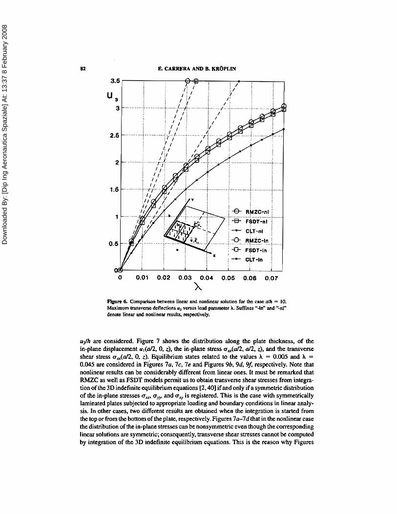
Figure 6. Comparison between linear and nonlinear solution for the case all, = 10. Maximum transve~se deflections 4 versus load paramctcr X. Suffiits "-h" and "-nl" denote linear and nonlinear nsulq respectively.
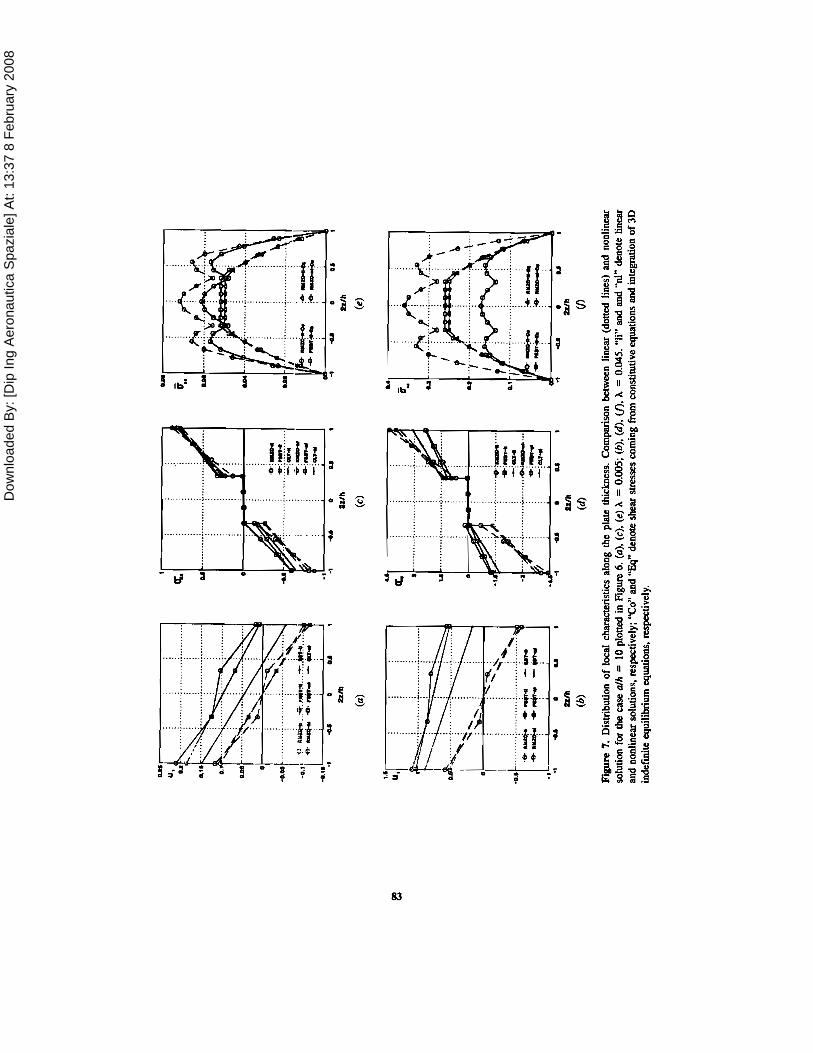
udh are considered. Figure 7 shows the distribution along the plate thickness, of the in-plane displacement ul(a/2, 0, z), the in-plane stress ada/2, a12, z), and the transverse shear stress u&/2, 0, z). Equilibrium states related to the values A = 0.005 and A = 0.045 are considered in ~i&res 7a, 7c, 7e and Figures 96, 9d, 9f, respectively. Note that nonlinear results can be considerably different from linear ones. It must be remarked that RMZC as well as FSDT models pennit us to obtain transverse shear stresses from integra- tion of the 3D indefinite equilibrium equations [2,40] if and only if a symmetric distribution of the in-plane stresses a, a, and a, is registered. This is the case with symmetrically laminated plates subjected to appropriate loading and boundary conditions in linear analy- sis. In other cases, two different res~ilts are obtained when the integration is started from the top or from the bottom of the plate, respectively. Figures 7a-7d that in the nonlinear case the distribution of the in-plane stresses can be nonsymmevic even though the corresponding linear solutions are symmetric; consequently, transverse shear stresses cannot be computed by integration of the 3D indefinite equilibrium equations. This is the reason why Figures
Dow
nloa
ded
By:
[Dip
Ing
Aer
onau
tica
Spa
zial
e] A
t: 13
:37
8 Fe
brua
ry 2
008
Dow
nloa
ded
By:
[Dip
Ing
Aer
onau
tica
Spa
zial
e] A
t: 13
:37
8 Fe
brua
ry 2
008
84 R CARRERA AND B. KROPLIN
7e and 7f restrict the results to the transverse stresses coming from constitutive equations (10) (CLT and FSDT would lead to a constant distribution of the shear in each layer). These values (see [32]) can be affected by considerable errors. The aim here is only to offer a comparison between results most probably affected by the same level of approxima- tion. From this point of view; Figures 7e and 7f show that in the very large deflection field very different results can be obtained for the transverse shear stresses by comparing linear and nonlinear analysis.
Postbuckling of Axially Compressed Plates
For the postbuckling analysis, full plates are considered with a mesh of 4 X 4 finite elements. Buckled paths have been calculated by applying a constant distribution of disturbance transverse pressure p,. Axially compressed plates, along the x direction, are examined. The reference axial load in the vector (Pd} consists of a five-point load P, = 2, applied at the comer nodes of the finite elements (see also the sketches in the subsequent figures). Such a distribution does not correspond to the constant distribution of in-plane displacement related to the linear solution. In fact, in the nonlinear case the behavior can be very different. The effects of edge stiffeners and various in-plane loading distributions are discussed in 1231 and are not included in the present analysis. In order to improve the computational performances of the Newton-Raphson method, the arc- length constraint proposed in [38, and 391 has been implemented.
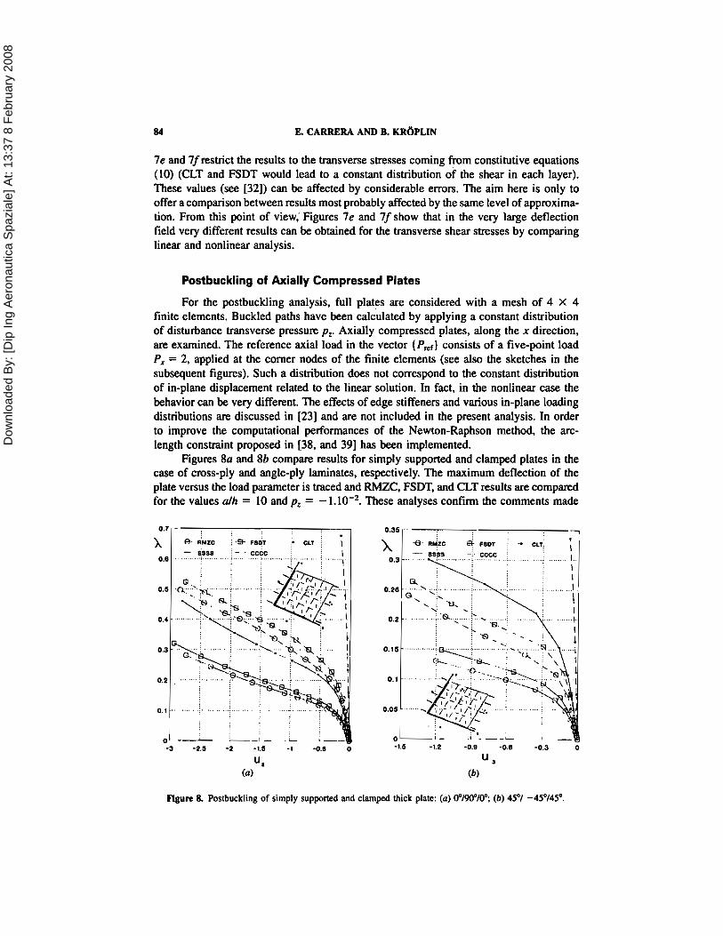
Figures 8a and 8b compare results for simply supported and clamped plates in the case of cross-ply and angle-ply laminates, respectively. The maximum deflection of the plate versus the load parameter is traced and RMZC, FSDT, and CLT results are compared for the values alh = 10 and p, = - 1.10-2. These analyses confirm the comments made
Figure 8. Postbuckling of simply supported and clamped thick plate: (a) 0"/90"/0"., (b) 45'1 -4S0/45".

Dow
nloa
ded
By:
[Dip
Ing
Aer
onau
tica
Spa
zial
e] A
t: 13
:37
8 Fe
brua
ry 2
008
ZIGZAG AND INTERLAMINAR EQUILIBRIA EFFECTS 85
in the previous subsection; in addition, these figures show that the results are very much subordinate to the layouts. Figure 9 considers the case of a cross-ply, simply supported plate. Thin plates, alh = 100 under p, = - l.10-5 are examined. One notes that for a thin plate, shear deformation effects are still evident in postbuckling analysis, while RMZC effects do not seem significant.
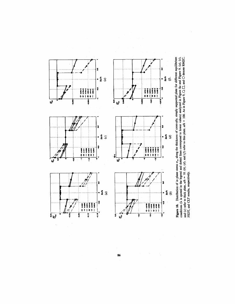
Since an arc-length procedure has been implemented, stress values corresponding to the same load level A cs to the same displacement level are not available. Thus Figures 10a-1Of show the distribution of the in-plane normal stress u, = uAa/2, d2, z) for six equilibrium states, corresponding to six load steps (for the same load step, different values of A have been found for the three models). One notices that the same load step means the same level of the Euclidean norm of the global vector (Q,); such a comparison could be more significant than the one used in the previous subsection. The two cases of thick and thin plates (Figure 80 and Figure 9, respectively) are compared. One confirms that in thick-plate analyses, higher-order shear deformation plays a fundamental role, especially in predicting local charactc:ristics, while FSDT results seem reasonably accurate to describe the in-plane response of the thin plates considered.
Figure 9. I~ostbuckling of mas-ply, simply supported thin plates.
Dow
nloa
ded
By:
[Dip
Ing
Aer
onau
tica
Spa
zial
e] A
t: 13
:37
8 Fe
brua
ry 2
008
936 g s # .r.
go; Y - 2 8 g ~4
" t ; E O i ig & - a 3 8 G s a
i g,: 3 iz c.5 g
iz 2 ,c h% ';: p i 4
*; 3 g i; 3 3 11 3 a $ E 3 o s i
* ( d
O I ? z
5 2 . 5 4 g S 3g; 3 2'gs 3 a 2 2 8 g r: Ca - E
Dow
nloa
ded
By:
[Dip
Ing
Aer
onau
tica
Spa
zial
e] A
t: 13
:37
8 Fe
brua
ry 2
008
ZIGZAG AND INT'ERLAMINAR EQUILIBRIA EFFECTS 87
CONlCLUDlNG REMARKS
Concerning HSDT plate mocleling of composite plates, this article has presented, for the first time, a numerical investigation of local characteristics in the large-deflection and postbuckling fields. Von KhBn-type nonlinearities have been considered in conjunc- tion with a mixed higher-order shear deformation model denoted by the acronym RMZC. The finite-element method and the: Newton-Raphson technique have been used in the numerical investigations. The results obtained permit the following conclusions.
1. The model has been seen as the extension to multilayered plates of the well- known C0 Reissner-Mindlin model; it has preserved numerical efficiency in both linear and geometrically nonlinear analysis; furthermore, it has led, as a particular case, to both FSDT and CLT results.
2. With respect to FSDT and CLT analyses, more accurate evaluations of the transverse shear stresses can be made by the use of the RMZC model; furthermore, the in-plane response has been very much improved in the case of highly aniso- tropic thick plates. For such plates the importance of transverse shear deformations as well as zigzag and interlaminar equilibria is confirmed; furthermore, these effects become more significant in the large-deflection and postbuckling fields. For thin plates, the conducted investigations have shown that FSDT results are reasonably accurate (with respect to RMZC analyses).
3. Future investigations should be directed toward different geometries and stacking sequences, as well as geometric-mechanical boundary conditions. Improvements should be introduced in the proposed two-dimensional model with more accurate predictions of nonsymmetric stress and displacements fields along the plate thickness. Furthermore, accurate evaluations of the transverse normal stress and related effects still remain open; attempts in this area should be made in the fields of layer-wise theories [lo], but in this context the computational costs at present do not allow this.
REFERENCES
1. J. M. Whitney and N. J. Pagano, Shear Deformation in Heterogeneous Anisotropic Plates, J. Appl. Mech., vol. 7, pp. 1031-1036, 1970.
2. J. N. Pagano, Exact Solutions for Clomposite Laminates in Cylindrical Bending, J. Composite Mater, vol. 5, pp. 20-34, 1969.
3. J. N. Pagano and S. J. Hatfield, Ellastic Behavior of Multilayered Bidirectional Composites, AIM J., vol. 10, pp. 931-933, 1972.
4. C. T. Sun and J. M. Whitney, Theories for Dynamic Response of Laminated Plates, AIAA J., vol. 11, pp. 178-183, 1973.
5. J. Albinger, C. Hansel, M. Konig, R. Kriiger, H. Parish, and S. Rinderknecht, Eine kombiniertes experimentelles und numerishes Verfahren zur Bestimmung der Energiefreisetzungraten beim Delaminationsfortschritt in CFK, in Numerishe und experimentelle Methoden in der Statik und Dynamik, ISD, University of Stuttgart, Stuttgart, 1994.
6. S. Rinderkencht and B. Krtiplin, A Finite Element Model for Delamination in Composite Plates, Mech. Composite Muter: Struct., vod. 2, pp. 19-47, 1995.
7. R. K. Kapania and S. Raciti, Recent Advances in Analysis of Laminated Beams and Plates, Part I: Shear effects and buckling, '41AA J., vol. 27, pp. 923-934, 1989.

Dow
nloa
ded
By:
[Dip
Ing
Aer
onau
tica
Spa
zial
e] A
t: 13
:37
8 Fe
brua
ry 2
008
88 & CARRERA AND B. K R ~ P L M
8. A. K. Noor and W. S. Burton, Assessment of Shear Deformation Theories for Multilayered Composite plates, Appl. Mech. Rev., VOI. 41, pp. 1-12, 1989.
9. J. N. Reddy and D. H. Robbins Jc, On Computational Strategies for the ~na l i s i s of Composite Laminates, Symp. on Advanced Technology on Design and Fabrication of Composite Materials
. and Structures, Torino, Italy, 24-28 May 1993. 10. E. Carrera, A Class of ' b o Dimensional Theories for Anisotropic Multilayered Plates Analysis,
Hem Sci. Fis., vol. 1 1-20, pp. 49-897, 1995. 11. J. Merk, D. Dinkler, and B. Wplin. Variable Kinematics for Hierarchical 3D-Shell Formulations.
prcprint, ISD-Bericht 95/10, UniversitP, Stuttgart, Stuttgart, Germany, 1995. 12. J. G. Ren, A New Theory for Laminated Plates, Composite Sci. Technol., vol. 26, pp. 225-
239, i986. 13. C. Y. Chia, Nonlinear Analysis of Anisotropic Plates, McGraw-Hill, New York, 1980. 14. C. Y. Chia, Geometrically Nonlinear Behavior of Composite Plates: A Review, Appl. Mech.
Rev., vol. 41, pp. 439-450, 1988. 15. A. N. Palazotto and C. T. Tsai. A Modified Riks Approach to Composite Shell Snapping Using
a Higher-Order Shear Deformation Theory, Comput. Stmct., vol. 35, pp. 221-226, 1990. 16. L. Librescu and M. Y. Wang, Imperfection sensitivity'and Postbuckling of Shear Deformable
Composite Doubly-Curved Shallow Panels, Int. J. Solids Stmct., vol. 29, pp. 1065-1083, 1992. 17. L. Librescu and M. Y. Wang, Effects of Geometric Imperfections on Vibrations of Compressed
Shear Deformable Composite Curved Panels, Acta Mech.. vol. 97. pp. 203-224. 1993. 18. E. Carrera,'On the Nonlinear Response of Asymmetrically Laminated Plates in Cylindrical
Bending, AIAA J., vol. 3 1, pp. 1353-1357. 1993. 19. J. N. Reddy, Georneuically Nonlinear Transient Analysis of Laminated Composites Plates,
AIAA J., vol. 21, pp. 621629, 1983. 20. W. C. Chao and J. N. Reddy, Large Deformation Analysis of Layered Composite Shells,
Mechanics of Composite Materials ASME AMD 58. pp. 19-31. 1983. 21. N. S. Putcha and J. N. Reddy, A Refined Mixed Shear Flexible Finite Element for the Nonlinear
Analysis of Laminated Plates, Comput. Struct., vol.. 22, pp. 529-538, 1986. 22. E. Carrera and M. Villazzo, Large Deflections and Stability FEM Analysis of Shear Deformable
Compressed Anisotropic Flat'Panels, Composite Stmct., vol. 29, pp. 433-444, 1994. 23. E. Canera and M. Villazzo, On the Effects of Boundary Conditions on Postbuckling of Com-
pressed, Symmetrically Laminated, Thick Plates, AIAAJ., vol. 33, pp. 1543-1546, 1995. 24. N. K. Chandiramani. R. H. Plaut, and L. I. Librescu, Non-linear Flutter of Buckled Shear
Deformable-Composite Panels in a High-Supersonic Flow. Int. J. Non-linear Mech., vol. 30, pp. 149-167, 1995.
.25. 0. Zienkiewicz, Finite Element Method, McGraw-Hill. New York. 1990. 26. M. A. Crisfield, Non-linear Finite Element Analysis of Solids and Structures. John Wiley,
Chichester, U.K., 1992. 27. B. Krl)plin and D. Dinkler. Stobilitdtstheorie, Mehlhom G. Handbuch fUr Bauingeniere, Ernst &
Sohn. Berlin. 1994. 28. A. N. Palazotto and S. T. Dennis. Nonlinear Analysis of Shell Structures, AIAA Ser. 1992. 29. J. N. Reddy, On Refined Computational Models of Composite Laminates, Int. 3.. Numer: Meth.
Eng., vol. 27, pp. 361-382, 1989. 30. A. K. Noor and W. S. Burton. Assessment of Computational Models for ~ultilayered Anisotropic
plates, Composite Stmcr..vol. 14, pp. 233-265, 1990. 31. B. N. Pandya and T. Kant, Flexural Analysis of Laminated Composites Using Refined Higher-
Order C0 Plate Bending Elements. Comput. Meth. Appl. Mech. Eng.. vol. 66, pp. 173-198, 1988. 32. E. Carrera, Co Reissner-Mindlin Multilayered Plate Elements Including Zig-Zag and Interlaminar
Stresses Continuity, Second EUROMECH Colloqiwn. Genova, 1994, Int. J. Nwner: Meth. Eng., vol. 39, pp. 1797-1820, 1996.
33. T. Kant and J. R. Kommineni, Large Amplitude Free vibrations Analysis of Cross-Ply Composite

Dow
nloa
ded
By:
[Dip
Ing
Aer
onau
tica
Spa
zial
e] A
t: 13
:37
8 Fe
brua
ry 2
008
ZIGZAG AND INTERLAMINAR EQUILIBRIA EFFECTS 89
and Sandwich Laminates with a Refined Thwry and Co Finite Elements, Comput. Struct., vol. 50, pp. 123-134, 1994.
34. H. Murakami. Laminated Composite Plate Theory with Improved In-plane Response, J. Appl. Mech.. vol. 53. pp. 661-666, 1986.
35. A. Toledano and H. Mwakami, A Higher-Order Laminated Plate Theory with Improved In- plane Stresses, Int. J. Solids Stmct.. vol. 23, pp. 111-131, 1987.
36. E. Reissner. Note on the Effect of the Transverse Shear Deformation in Laminated Plates. Comput. Meth Appl. Mech. Eng., vol. 20, pp. 203-209, 1979.
37. E. Carrera, Large Deflection Behavior and Incremental Strategies in the FEM Analysis of Composite Sauctures, ISD Bericht 10192, University of Stuttgart, Stuttgart, Germany, 1992.
38. E. Carrera, Comportamento postcritico di gusci multistrato. Ph. D. thesis. DIAS. Politecnico di Torino, Turin, Italy, 1992.
39. E. Carrera, A Study on Arc-Length-Type Methods and Their Operation Failures Illustrated by a Simple Model, Comput. Snuct., vol. 50, pp. 217-229, 1994.
40. R. M. Jones, mechanic,^ of Composire Materials, McGraw-Hill, New York, 1975. 41. 1. N. Reddy. A Simple :Higher-Order Theory for Laminated Composite Plates, J. AppL Mech..
vol. 51, pp. 745-752. 1984. 42. M. Di Sciuva, Multilayered Anisotropic Plate Models with Continuous Interlaminar Stresses,
Composite Struct,, vol. 22, pp. 149-167, 1993.
APPEiNDlX A: EXPLICT FORM OF ARRAYS
Strain-displacemens mlations:
Hooke's law:
(&I:' = (dl. 42.421 {@)I = ( 4 3 , &I (28)

Dow
nloa
ded
By:
[Dip
Ing
Aer
onau
tica
Spa
zial
e] A
t: 13
:37
8 Fe
brua
ry 2
008
lL CARRERA AND B. KR~PLIN
The relation between the stiffness coefficients CQ (i, j = 1, 2, 6, 4, 5) and mechanical characteristics of the lamina (Young and shear moduli Bs well as Poisson coefficients) can be found in [40]. Naturally, these formulas must be related to the Ok orientation of the fibers with respect to the x axis.
Displacement and stress models:
The element of matrices and [Eolk other than zero are
Coupled superscripts denote the rows and columns, respectively, of the matrices considered Matrices [&Ik and [Wlk: For the matrix [&Ik, the compliance coefficients are used.
The matrix [Hulk is not symmetric, and the elements other than zero are
Dow
nloa
ded
By:
[Dip
Ing
Aer
onau
tica
Spa
zial
e] A
t: 13
:37
8 Fe
brua
ry 2
008
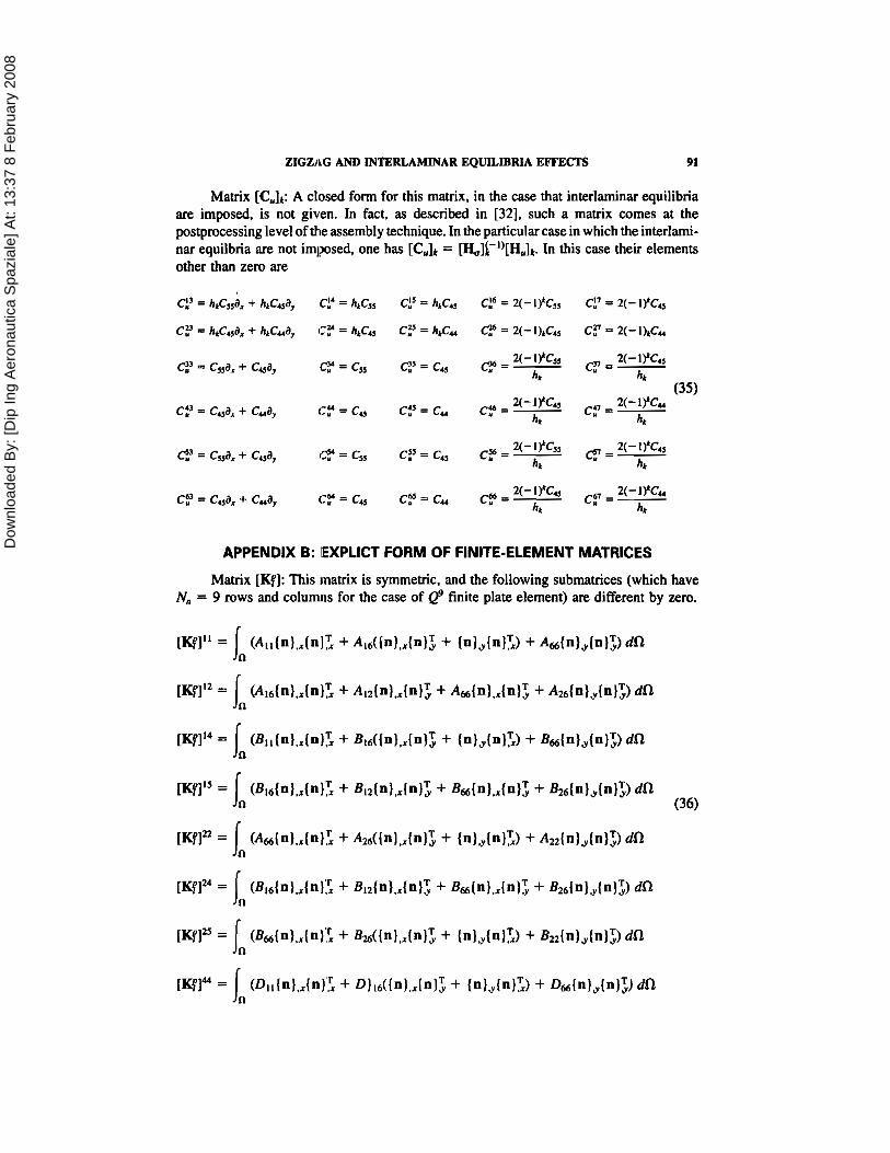
ZIGZAG AND INTERLAMINAR EQUILIBRIA EFFECTS 91
Matrix [Culk: A closed form for this matrix, in the case that interlaminar equilibria are imposed, is not given. In fact, as described in [32], such a matrix comes at the postprocessing level of the assembly technique. In the particular case in which the interlami- nar equilbria are not imposed, one has [CUlk = [&]i-"[HUlk. In this case their elements other than zero are
C3 a cssax + cad, C = c,, C5 = cdS 2(- IYCss c=- 2(- 1 rc45 e=- hk hk
2(- 1YCu (35)
cp = cua, + cud, t7y = cU c:' = cu cp = - hk n,
APPENDIX B: IEXPLICT FORM OF FINITE-ELEMENT MATRICES
Matrix [Kf]: This matrix is symmetric, and the following submatrices (which have N, = 9 rows and colunu~s for the case of Q' finite plate element) are different by zero.
Dow
nloa
ded
By:
[Dip
Ing
Aer
onau
tica
Spa
zial
e] A
t: 13
:37
8 Fe
brua
ry 2
008
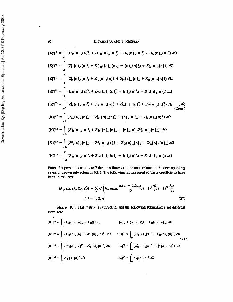
92 E. CARRERA AND B. K R ~ P L I N
Pairs of superscripts from 1 to 7 denote stiffness components related to the corresponding seven unknown subvectors in (Q,). The following multilayered stiffness coefficients have been introduced:
Matrix [Kn]: This matrix is symmetric, and the following submatrices are different from zero.

Dow
nloa
ded
By:
[Dip
Ing
Aer
onau
tica
Spa
zial
e] A
t: 13
:37
8 Fe
brua
ry 2
008
ZIGZAG AND ENTERLAMINAR EQUILIBRIA EFFECTS
m l S 7 = a (n) (n). dfl n
As for the matrix [C,Ik, a closed form of the introduced multilayered stiffness coeficient is not given. In the particular case in which interlaminar equilibria are not imposed, they read
It must be stressetl that the differential operators in the shear stiffness matrix do not change when interlarninar equilibria are imposed. That is, the technique described in the text only modifies the multilayered stiffness. In this sense such a method can be seen as an automatic way of 1:ornputing shear correction factors.
Matrices [Kfnl] and [K$,]: These are nonsymmetric matrices whose submatrices other than zero are
[Khl" = ] (Bt6(n),, (n)>, + BIZ(^).. {nI>3., + 2B~[nl.,lnJ>1,~ + ~ ~ ( n ) , l n l > 3 , , , n
+ 2Bsa(n), (n)33,, + 2B26(n).x ln1>3, + B2,(nl.y(n)>,y + B22(nIa (n133.J dfi
and

Dow
nloa
ded
By:
[Dip
Ing
Aer
onau
tica
Spa
zial
e] A
t: 13
:37
8 Fe
brua
ry 2
008
94 E. CARRERA AND 8. KROPLIN
Matrix [KGI]: This is a symmetric maaix whose unique submatrix other than zero is
Matrices [bl] and [&I: These two matrices are symmetric, and their submatrices other than zero are, respectively,
The following multilayered in-plane stress resultants have been introduced: