Embed Size (px)
Citation preview
* +
ISSN 1018-5593
European Commission
technical steel research
Mechanical working (rolling mills)
Application of finite elements method in hot rolling and deep drawing
STEEL RESEARCH

European Commission
technical steel research Mechanical working (rolling mills)
Application of finite elements method in hot rolling and deep drawing
M. Mirabile,1 J. Bianchi,1 R. Buenten,2 P. Buessler,3 P. Ingham,4
M. Mamalis,5 G. Monfort,6 F. Requejo,7 P. Turpel8
1Centro sviluppo materiali SpA 2IBF
3IRSID "British Steel
5National Technical University of Athens 6Centre de recherches metallurgiques
7Ensidesa sArbed recherches
Contract No 7210-EB/406
1 January 1989 to 31 December 1991
Final report
Directorate-General Science, Research and Development
1997 EUR 15803 EN

LEGAL NOTICE
Neither the European Commission nor any person acting on behalf of the Commission is responsible for the use which might be made of the following information)
A great deal of additional information on the European Union is available on the Internet. It can be accessed through the Europa server (http://europa.eu.int)
Cataloguing data can be found at the end of this publication
Luxembourg: Office for Official Publications of the European Communities, 1997
ISBN 92-828-0744-4
© European Communities, 1997 Reproduction is authorized, provided the source is acknowledged
Printed in Luxembourg
LIST OF CONTENTS
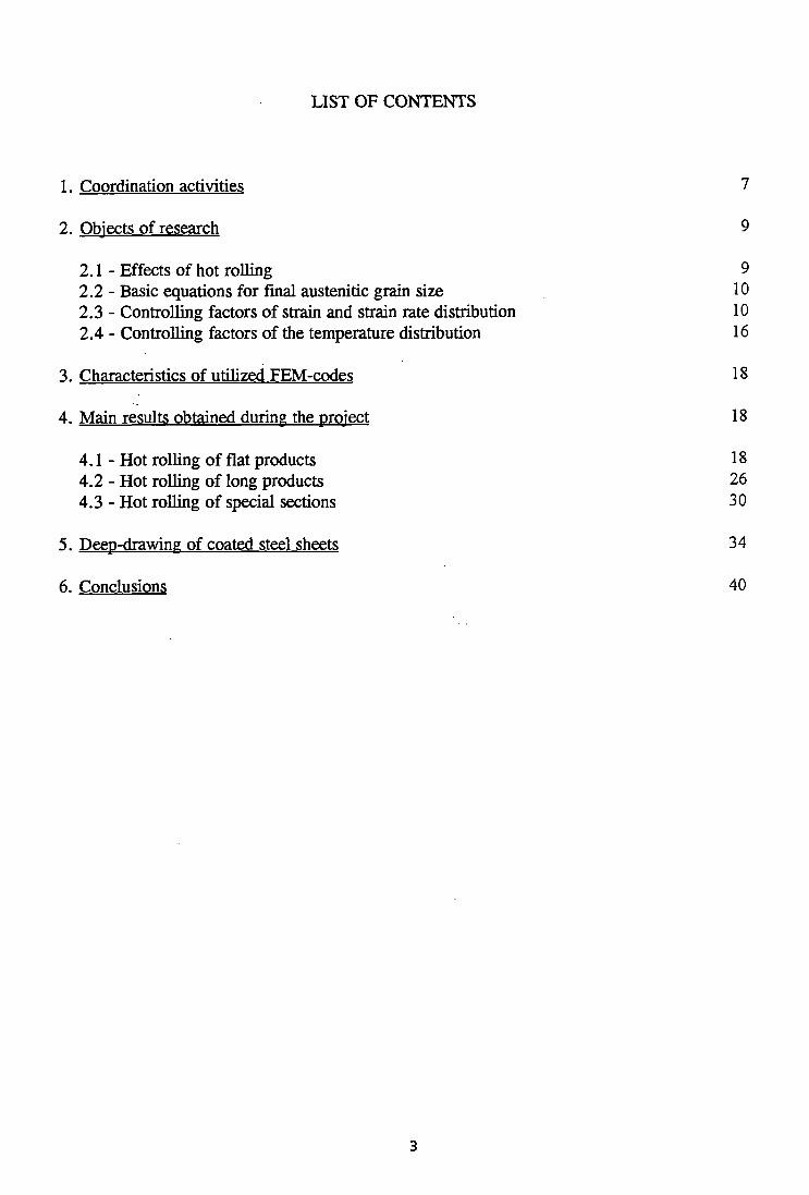
1. Coordination activities 7
2. Objects of research 9
2.1 - Effects of hot rolling 9 2.2 - Basic equations for final austenitic grain size 10 2.3 - Controlling factors of strain and strain rate distribution 10 2.4 - Controlling factors of the temperature distribution 16
3. Characteristics of utilized FEM-codes 18
4. Main results obtained during the project 18
4 . 1 - Hot rolling of flat products 18 4.2 - Hot rolling of long products 26
4.3 - Hot rolling of special sections 30
5. Deep-drawing of coated steel sheets 34
6. Conclusions 40
LIST OF FIGURES
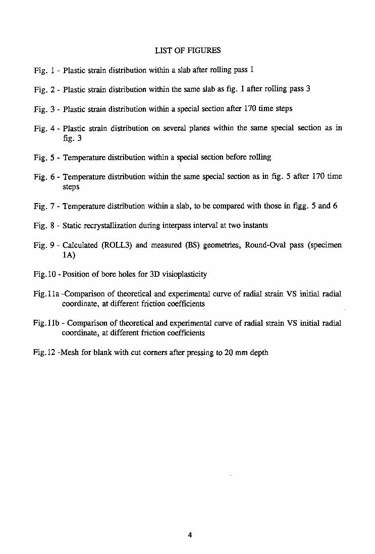
Fig. 1 - Plastic strain distribution within a slab after rolling pass 1
Fig. 2 - Plastic strain distribution within the same slab as fig. 1 after rolling pass 3
Fig. 3 - Plastic strain distribution within a special section after 170 time steps
Fig. 4 - Plastic strain distribution on several planes within the same special section as in fig. 3
Fig. 5 - Temperature distribution within a special section before rolling
Fig. 6 - Temperature distribution within the same special section as in fig. 5 after 170 time steps
Fig. 7 - Temperature distribution within a slab, to be compared with those in figg. 5 and 6
Fig. 8 - Static recrystallization during interpass interval at two instants
Fig. 9 - Calculated (ROLL3) and measured (BS) geometries, Round-Oval pass (specimen 1A)
Fig. 10 - Position of bore holes for 3D visioplasticity
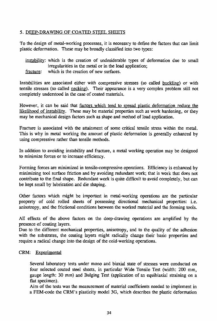
Fig. 11a -Comparison of theoretical and experimental curve of radial strain VS initial radial coordinate, at different friction coefficients
Fig. 1 lb - Comparison of theoretical and experimental curve of radial strain VS initial radial coordinate, at different friction coefficients
Fig. 12 -Mesh for blank with cut corners after pressing to 20 mm depth
LIST OF TABLES
Tab. I - Synoptic frame of all partners' involvement
Tab. 1 - Comparison of measured rolling force and torque with values given by Lagamine code. Flat products
Tab. 2 - Comparison of total spread values as resulting from experiments and theoretical extimation with ROLL3 code. Flat products
Tab. 3 - Comparison of calculated (ROLL3) and measured (MEFOS) values of force and torque. (Total force means sum of the forces of both sides of a roll, total torque is the torque for both rolls). Flat products
Tab. 4 - Comparison of calculated (DYNA3) and measured (MEFOS) values of force, upper and lower torque. Flat products
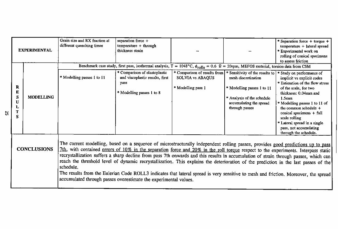
Tab. 5 -Working Unit 1: Flat products
Tab. 6 - Comparison of calculated (ROLL3) and measured (BS) values of rolling force and torque. Long products
Tab. 7 - Working Unit 2: Hot rolling of long products
Tab. 8 - Working Unit 3: Hot rolling of special sections
Tab. 9 - Working Unit 4: Sheet forming

APPLICATION OF FINITE ELEMENT METHODS (FEM) IN
HOT ROLLING AND DEEP-DRAWING OF STEELS
Collaborative Research Program SWENDEN/ECSC
1.12.88-31.12.91
Final Report of coordination activities and scientific results
1. COORDINATION ACTIVITIES
For the purpose of a good coordination four Working Units were appointed:
- Working Unit 1: Hot rolling of flat products Partners: ARBED, CSM, ENSIDESA, IRSID, MEFOS
- Working Unit 2: Hot rolling of long products Partners: BS, IRSID
- Working Unit 3: Hot rolling of special sections Partners: IRSID, RWTH
- Working Unit 4: Deep-drawing of coated steel sheets Partners: CRM, NTU, SIMR
A synoptic frame of all partners' involvement is given in tab. I.
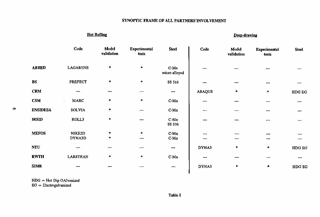
SYNOPTIC FRAME OF ALL PARTNERS'INVOLVEMENT
Hot Rolling
oo
ARBED
BS
CRM
CSM
ENSIDESA
IRSLD
MEFOS
NTIT
RWTH
SIMR
Code
LAGAMINE
PREFECT
—
MARC
SOLVIA
ROLL3
NIKE2D DYNA3D
LARSTRAN
—
HDG = Hot Dip GAlvanized EG = Electrogalvanized
Model validation
*
*
—
*
*
*
* *
*
—
Experimental tests
*
*
—
*
—
—
*
*
—
Steel
C-Mn micro alloyed
SS316
...
C-Mn
C-Mn
C-Mn SS316
C-Mn C-Mn
C-Mn
—
Code
ABAQUS
DYNA3
DYNA3
Deep-drawing
Model Experimental validation tests
Steel
HDG EG
HDG EG
HDG EG
Table I
Since the commencement of the research on December 1988, five information days were held, aiming at allowing all partners to discuss methodologies of work, define experimental procedures, compare intermediate results and performances of several FEM Codes and accordingly agree common future strategies. The information days were held in Rome (9.12.88), Stockholm (17.10.89), Aviles (22.6.90), Rotherham (7.6.91), Rome (27.9.91). In addition, several informal meeting were organized among the partners involved in the same Working Unit in order to agree
- same steel grades; - same rolling schedules; - same geometries of blanks and punchs.
Every six months, progress reports were forwarded to the Commission, presented and discussed by the appropriate Executive Committees. Every report based on the semestrial contribution of each partner, summarized the most significant topics: delays, technical difficulties, management of material supply among partners, convergence of results, readjustment of initial tasks, etc. Six semestrial reports have been totally draft. The final reports were discussed and formally approved by the Executive Committee D3 in Paris on May, 15 1992 (Final Report relevant the Hot Rolling activities) and by the Executive Committee F4 in Brussels on June, 28 1992 (Final Report relevant to the Deep-Drawing activities).
2. OBJECTS OF RESEARCH
Hot rolling: to describe the strain-temperature evolution inside the rolled piece in order to achieve a strict control of * the microstructure * the geometry
Cold deep-drawing: to describe the progressive time changing in the properties of coated steel sheets brought about by cold forming process parameters: punch velocity, friction coefficients between tool and sheets, etc.
2.1) Effects of hot rolling
Many carbon steels are used in the form of as-rolled finished sections, whose micro-structures and properties are largely determined by the composition, the rolling practice and the cooling conditions after rolling. The rolling, ordinarily carried out in temperature ranges at which the steel is austenitic, has effects as follows:
- the dendritic structure is broken up; - recrystallization process occur so that the final austenitic grain size is determined by the
finishing temperature; - dendrites, inclusions and porosities, are reoriented in the rolling direction so that the final
ductility in the rolling direction is markedly improved.
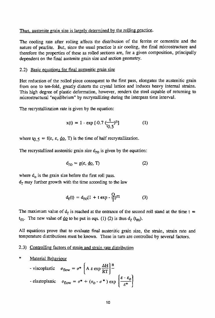
Thus, austenite grain size is largely determined bv the rolling practice.
The cooling rate after rolling affects the distribution of the ferrite or cementite and the nature of pearlite. But, since the usual practice is air cooling, the final microstructure and therefore the properties of these as rolled sections are, for a given composition, principally dependent on the final austenite grain size and section geometry.
2.2) Basic equations for final austenitic grain size
Hot reduction of the rolled piece consequent to the first pass, elongates the austenitic grain from one to ten-fold, greatly distorts the crystal lattice and induces heavy internal strains. This high degree of plastic deformation, however, renders the steel capable of returning to microstructural "equilibrium" by recrystallizing during the interpass time interval.
The recrystallization rate is given by the equation:
x(t) = 1 - exp [-0.7 <^ )n j (i)
where tQ 5 = f(£, £, do, T) is the time of half recrystallization.
The recrystallized austenitic grain size dr0 is given by the equation:
dro = g(e, do, T) (2)
where d0 is the grain size before the first roll pass. dr may further growth with the time according to the law
d r ( t ) = d r o ( l + t e x p - ^ ) m (3)
The maximum value of dr is reached at the entrance of the second roll stand at the time t = tm. The new value of do to be put in eqs. (1) (2) is thus dr (tm).
All equations prove that to evaluate final austenitic grain size, the strain, strain rate and temperature distributions must be known. These in turn are controlled by several factors.
2.3) Controlling factors of strain and strain rate distribution
* Material Behaviour
- viscoplastic aflow = a*
- elastoplastic aflow = a* + (a0 - a * ) exp
10
A A H
A £ exp — £ - £ 0
e-s0 - elastoviscoplastic aflow = a*(e) + [a0 - a* (e)] exp
* Friction laws and coefficients
- Coulomb's law: F = /xN F = friction force H = friction coefficient N = normal force
- Norton shear friction: T ~ my a m = friction coefficient
vrel r\ = arctang ——, varies locally along the contact arc [B=l % rolling speed] 13 Vrei = relative velocity workrolls-slab
- Friction anisotropy along width and rolling directions
* Scale influence on the friction - flow shear stress of wiistite - scale thickness
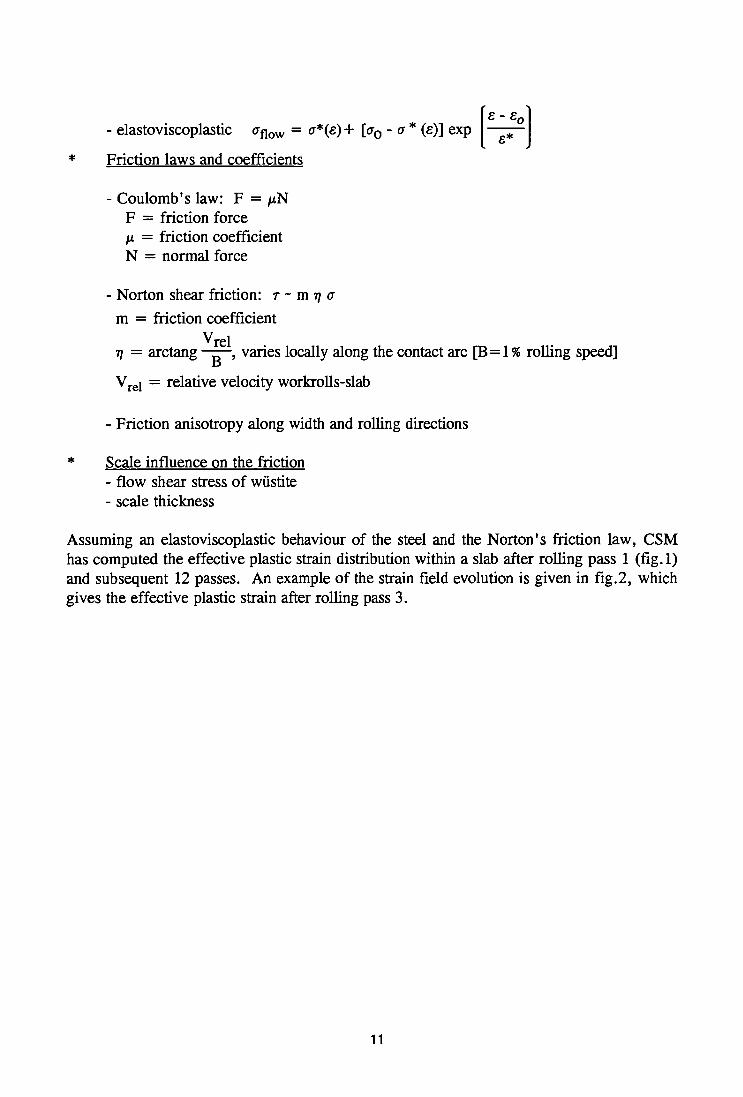
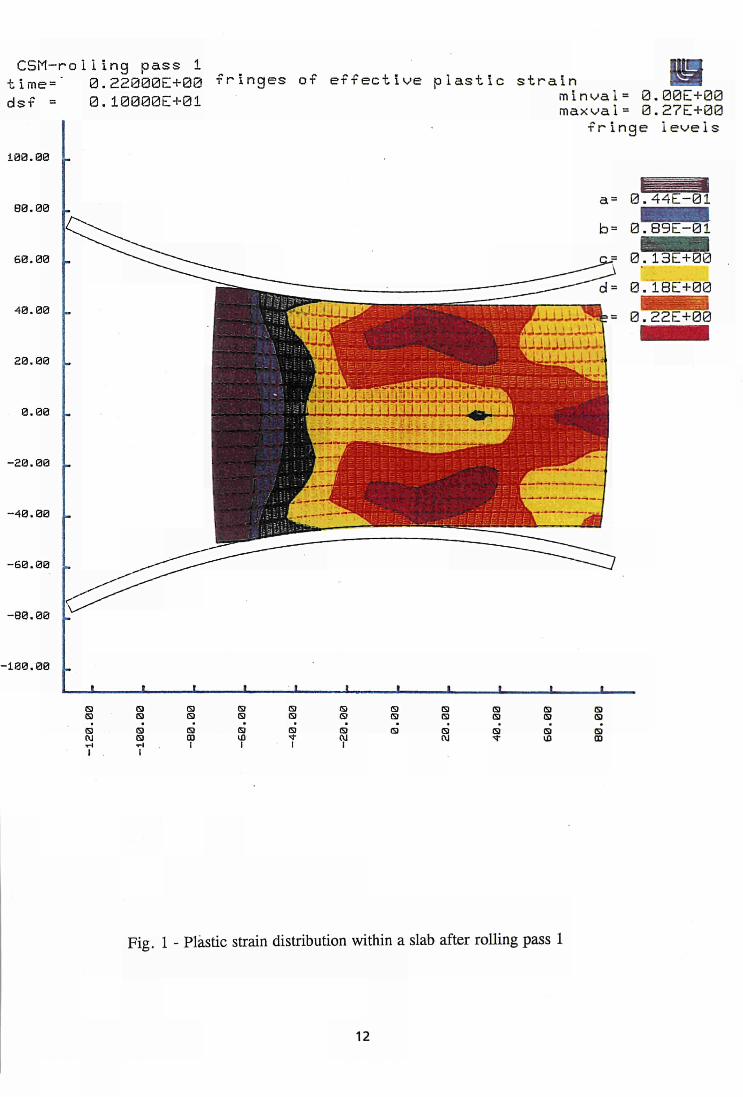
Assuming an elastoviscoplastic behaviour of the steel and the Norton's friction law, CSM has computed the effective plastic strain distribution within a slab after rolling pass 1 (fig.l) and subsequent 12 passes. An example of the strain field evolution is given in fig.2, which gives the effective plastic strain after rolling pass 3.
11

CSM-roliing pass 1 time=' 0.22000E+00 fringes of effective plastic strain ds f =
100.00
80.00
60.00
40.00
20.00
0.00
-20.00
-40.00
-60.00
0 . 1 0 0 0 0 E + 0 1 minval= 0.00E+00 maxval= 0.27E+00
fringe levels
a= B.44E-01 b= 0.S9E-01
0.13E+00 d= 0.18E+00
U.LUJiJWb = 0 . 2 2 E + 0 0
-80.00
100.00
•
5) (3 W
•
(9
(9 G>
•
00 1
• <3 S)
S>
1
»
<9 (9
1
f
®
•
<9 Q (9
1
<9 19 (9
•
(9 (9 (9
t
(9 <9 (9
■
S)
§
Fig. 1 - Plastic strain distribution within a slab after rolling pass 1
12

CSM-roiling pass 3 time" 0.21000E+00 fringes of effective plastic strain dsf =
108.00 .
80.00 .
60.00 .
40.00 .
20.00 .
0.00 _
-30.00 .
-40.00 .
-60.00 .
-80.00 .
-100.00 .
0.10000E+01 minvai= 0.00E+00 maxvai= 0.36E+00
fringe levels
a = 0.60E-01 b= 0rr2E+00
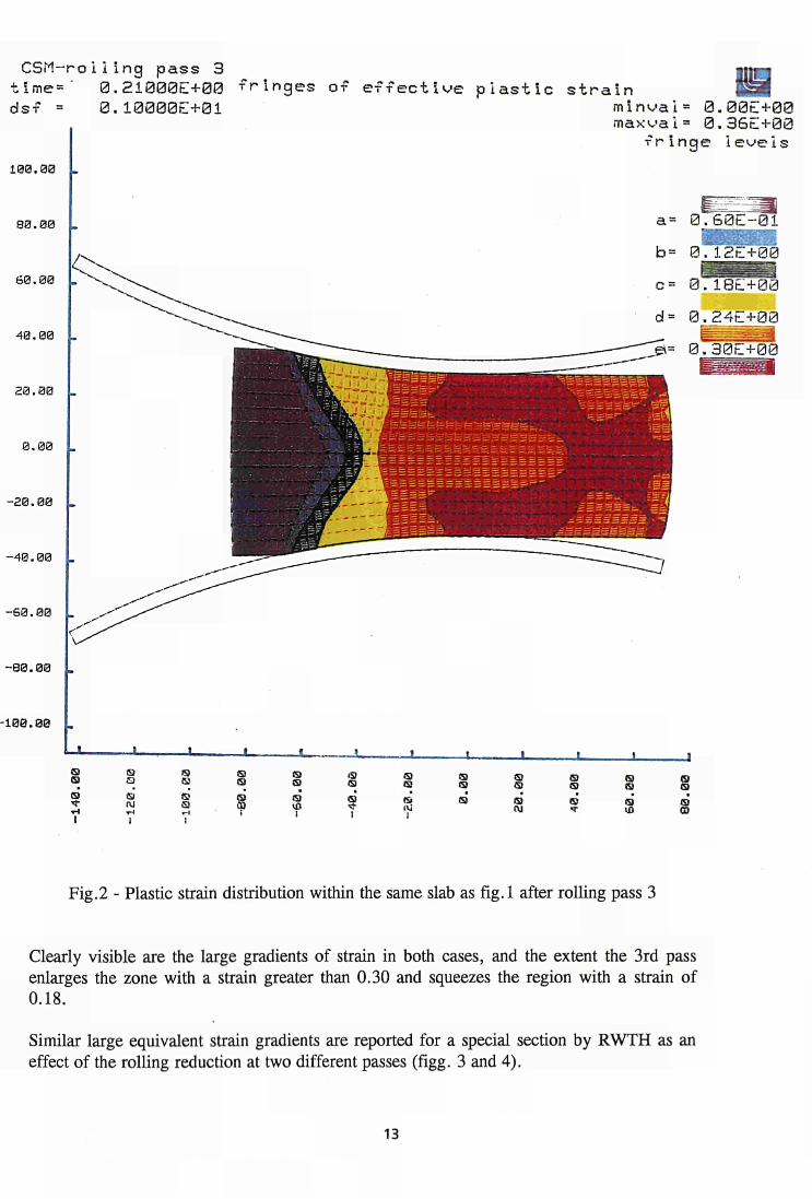
Fig.2 - Plastic strain distribution within the same slab as fig.l after rolling pass 3
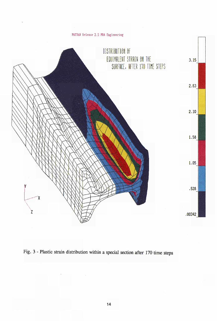
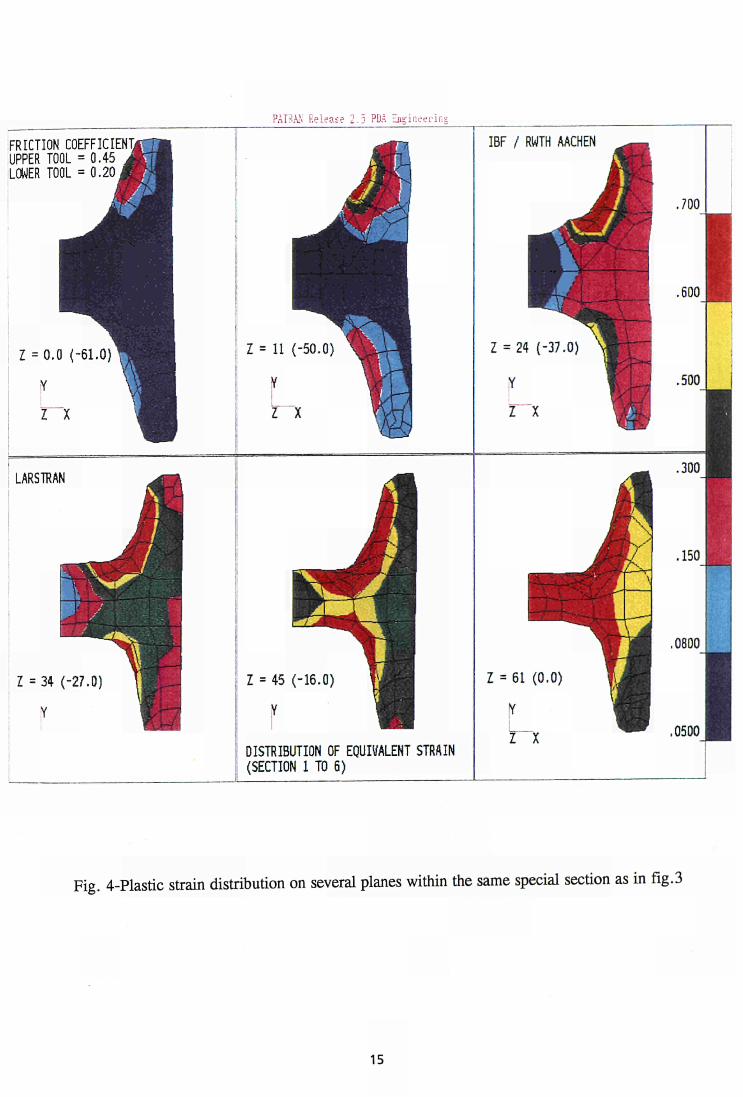
Clearly visible are the large gradients of strain in both cases, and the extent the 3rd pass enlarges the zone with a strain greater than 0.30 and squeezes the region with a strain of 0.18.
Similar large equivalent strain gradients are reported for a special section by RWTH as an effect of the rolling reduction at two different passes (figg. 3 and 4).
13

PATRAN Release 2.5 PDA Engineering
rami™ OE EQUIVALENT STRRIN OK THE
SURFACE, RFTER H O HUE SIEPS 3.15
2.63
2.10
1.58
1.05
.528
.00342
Fig. 3 - Plastic strain distribution within a special section after 170 time steps
14

PATRAN Release 2.5 PDA Engineering
FRICTION COEFFICIENT! UPPER TOOL = 0.45 LOWER TOOL = 0.20,
LARSTRAN
Z = 34 (-27.0)
Z = 1L (-50.0)
DISTRIBUTION OF EQUIVALENT STRAIN (SECTION 1 TO 6)
IBF / RWTH AACHEN
.700
.500
.300
.150
.0800
.0500
Fig. 4-Plastic strain distribution on several planes within the same special section as in fig.3
15

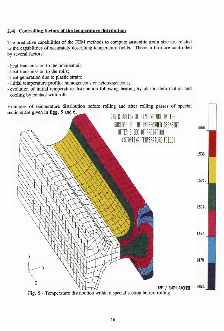
2.4) Controlling factors of the temperature distribution
The predictive capabilities of the FEM methods to compute austenitic grain size are related to the capabilities of accurately describing temperature fields. These in turn are controlled by several factors:
- heat transmission to the ambient air; - heat transmission to the rolls; - heat generation due to plastic strain; - initial temperature profile: homogeneous or hetereogeneous; - evolution of initial temperature distribution following heating by plastic deformation and
cooling by contact with rolls.
Examples of temperature distribution before rolling and after rolling passes of special sections are given in fig g . 5 and 6 ^ DISTRIBUTION DE T E M P E R A T U R E ON THE
1556.
TEMPERATURE FIELDI
1538.
1521.
1504.
1487.
1470.
IBF / RW1H AACHEN U 5 3-Fig. 5 - Temperature distribution within a special section before rolling
16

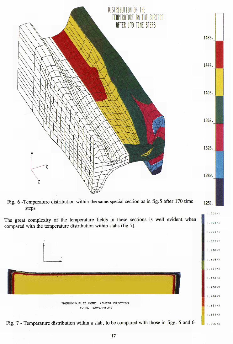
Fig. 6 -Temperature distribution within the same special section as in fig.5 after 170 time steps
The great complexity of the temperature fields in these sections is well evident when compared with the temperature distribution within slabs (fig.7).
THERMOCOUPLES MODEL iSHERR F R I C T I O N '
TOTRL TEMPERATURE
1483.
1444.
1405.
1367.
1328.
1289.
1251.
I . 0 8 1 + 3
I . 9 9 3 + 3
1 . 1 3 6 +3
1 . 1 1 9 + 3
1 . 1 3 1 + 3
I . 1 4 3 + 3
I - 1 5 6 + 3
I . 1 8 I +3
1 . 1 3 3 + 3
Fig. 7 - Temperature distribution within a slab, to be compared with those in figg. 5 and 6 ;a , .ZQS+2
17

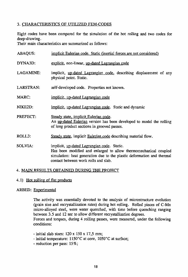
3. CHARACTERISTICS OF UTILIZED FEM-CODES
Eight codes have been compared for the simulation of the hot rolling and two codes for deep-drawing. Their main characteristics are summarized as follows:
ABAQUS:
DYNA3D:
LAGAMINE:
LARSTRAN:
MARC:
NIKE2D:
PREFECT:
ROLL3:
SOLVIA:
implicit Eulerian code. Static (inertia! forces are not considered)
explicit, non-linear, up-dated Lagrangian code
implicit, up-dated Lagrangian code, describing displacement of any physical point. Static.
self-developed code. Properties not known.
implicit, up-dated Lagrangian code
implicit, up-dated Lagrangian code. Static and dynamic
Steady state, implicit Eulerian code. An up-dated Eulerian version has been developed to model the rolling of long product sections in grooved passes.
Steady state, implicit Eulerian code describing material flow.
implicit, up-dated Lagrangian code. Static. Has been modified and enlarged to allow thermomechanical coupled simulation: heat generation due to the plastic deformation and thermal contact between work rolls and slab.
4. MAIN RESULTS OBTAINED DURING THE PROJECT
4.1) Hot rolling of flat products
ARBED: Experimental
The activity was essentially devoted to the analysis of microstructure evolution (grain size and recrystallization rates) during hot rolling. Rolled pieces of C-Mn micro-alloyed steel, were water quenched, with time before quenching ranging between 3.5 and 12 sec to allow different recrystallization degrees. Forces and torques, during 4 rolling passes, were measured, under the following conditions:
- initial slab sizes: 120 x 150 x 17,5 mm; - initial temperature: 1150°C at core, 1050°C at surface; - reduction per pass: 15%;
18
- rolling speed: 0,3 msec"1
Modelling
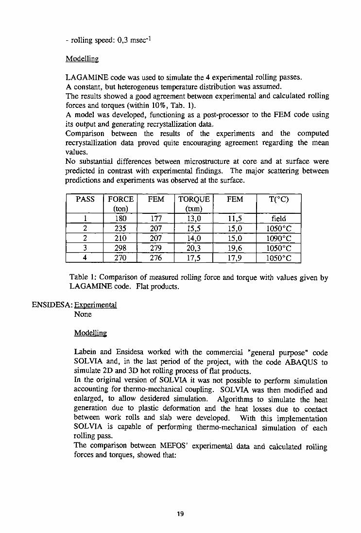
LAGAMINE code was used to simulate the 4 experimental rolling passes. A constant, but heterogeneus temperature distribution was assumed. The results showed a good agreement between experimental and calculated rolling forces and torques (within 10%, Tab. 1). A model was developed, functioning as a post-processor to the FEM code using its output and generating recrystallization data. Comparison between the results of the experiments and the computed recrystallization data proved quite encouraging agreement regarding the mean values. No substantial differences between microstructure at core and at surface were predicted in contrast with experimental findings. The major scattering between predictions and experiments was observed at the surface.
PASS
1 2 2 3 4
FORCE (ton) 180 235 210 298 270
FEM
177 207 207 279 276
TORQUE (txm) 13,0 15,5 14,0 20,3 17,5
FEM
11,5 15,0 15,0 19,6 17,9
T(°C)
field 1050°C 1090°C 1050°C 1050°C
Table 1: Comparison of measured rolling force and torque with values given by LAGAMINE code. Flat products.
ENSIDESA: Experimental None
Modelling
Labein and Ensidesa worked with the commercial "general purpose" code SOLVIA and, in the last period of the project, with the code ABAQUS to simulate 2D and 3D hot rolling process of flat products. In the original version of SOLVIA it was not possible to perform simulation accounting for thermo-mechanical coupling. SOLVIA was then modified and enlarged, to allow desidered simulation. Algorithms to simulate the heat generation due to plastic deformation and the heat losses due to contact between work rolls and slab were developed. With this implementation SOLVIA is capable of performing thermo-mechanical simulation of each rolling pass. The comparison between MEFOS' experimental data and calculated rolling forces and torques, showed that:
19
a divergence exists between experimental forces and numerical results, probably due to a mesh locking effect of the SOLVIA FEM formulation;
total torque values are in the range of a 10% of error;
there is a large difference in the pressure distribution along the roll bite between the code SOLVIA and other codes, like NIKE. The values calculated by SOLVIA are higher. The divergence appears in the contact zone and could be due to its finite element formulation.
ER.SID: Experimental None
Modelling
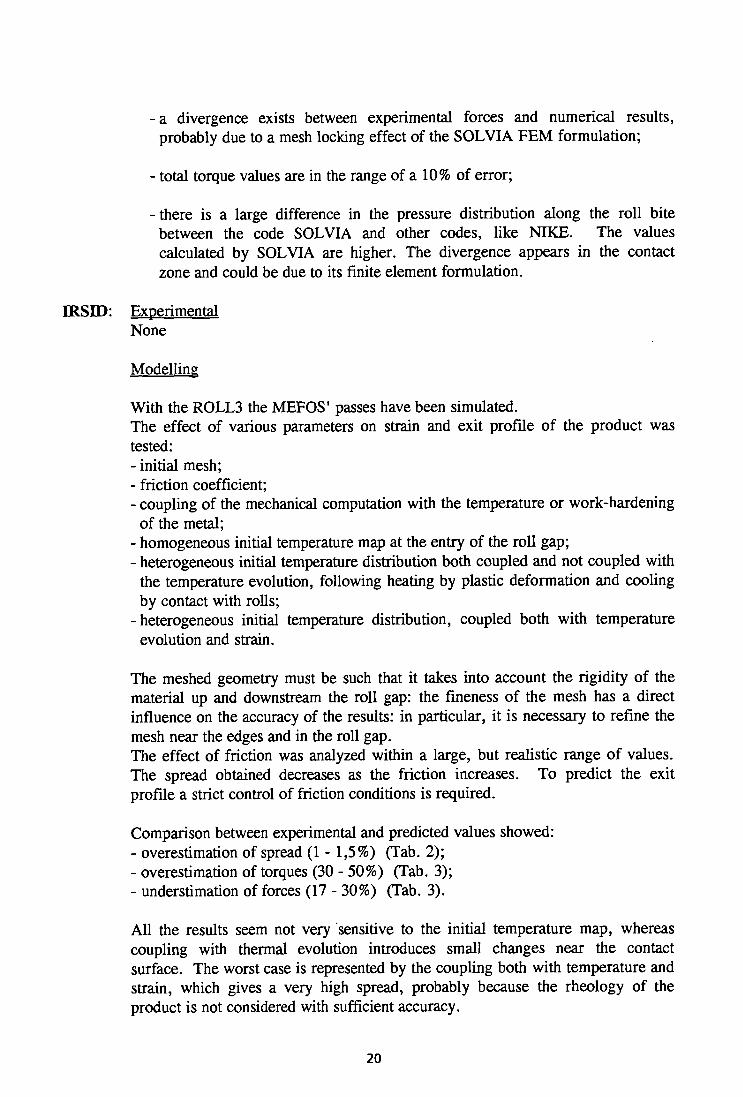
With the ROLL3 the MEFOS' passes have been simulated. The effect of various parameters on strain and exit profile of the product was tested: - initial mesh; - friction coefficient; - coupling of the mechanical computation with the temperature or work-hardening
of the metal; - homogeneous initial temperature map at the entry of the roll gap; - heterogeneous initial temperature distribution both coupled and not coupled with
the temperature evolution, following heating by plastic deformation and cooling by contact with rolls;
- heterogeneous initial temperature distribution, coupled both with temperature evolution and strain.
The meshed geometry must be such that it takes into account the rigidity of the material up and downstream the roll gap: the fineness of the mesh has a direct influence on the accuracy of the results: in particular, it is necessary to refine the mesh near the edges and in the roll gap. The effect of friction was analyzed within a large, but realistic range of values. The spread obtained decreases as the friction increases. To predict the exit profile a strict control of friction conditions is required.
Comparison between experimental and predicted values showed: - overestimation of spread (1 - 1,5%) (Tab. 2); - overestimation of torques (30 - 50%) (Tab. 3); - understimation of forces (17 - 30%) (Tab. 3).
All the results seem not very sensitive to the initial temperature map, whereas coupling with thermal evolution introduces small changes near the contact surface. The worst case is represented by the coupling both with temperature and strain, which gives a very high spread, probably because the rheology of the product is not considered with sufficient accuracy.
20
Pass
1 2 3 4
MEFOS Specimen
C6001 C6002 C6003 C6004
trials Wm
352.1 356.2 361.3 368.6
ROLL3 Wm
354.9 359.0 366.6 374.6
Difference %
0.80 0.79 1.47 1.63
Table 2: Comparison of total spread values as resulting from experiments and theoretical extimation with ROLL3 code. Flat products.
• •
pass
1 2 3 4
temp °C
1070 1069 1058 1056
Total force (ton)
MEFOS 174.1 202.0 359.9 393.5
ROLL3 144.50 153.01 264.64 275.50
diff(%) -17.00 -24.25 -26.47 -29.99
Total torque ( t xm)
MEFOS 11.13 14.36 27.69 28.50
ROLL3 16.76 18.38 40.48 37.34
diff(%) 50.58 27.99 46.19 31.02
Specimen C6004
Table 3: Comparison of calculated (ROLL3) and measured (MEFOS) values of force and torque. (Total force means sum of the forces of both sides of a roll, total torque is the torque for both rolls). Flat products.
MEFOS: Experimental
Rolling of four specimens on C-Mn steel, on a pilot plant was performed according to the agreed schedule:
Pass no furnace 1220°C
descaling by water 1 2 3 4
time (sec) 0 20 45 55 65 75
thickness (mm) — —
87 74
51.5 33.0
The material parameters were taken from hot torsion and plane strain compression tests at CSM and all the geometrical data were recorded during the experiments. The measured forces and torques were very consistent from specimen to specimen.
Modelling NIKE2D and DYNA3D codes were used respectively for the two-three
21
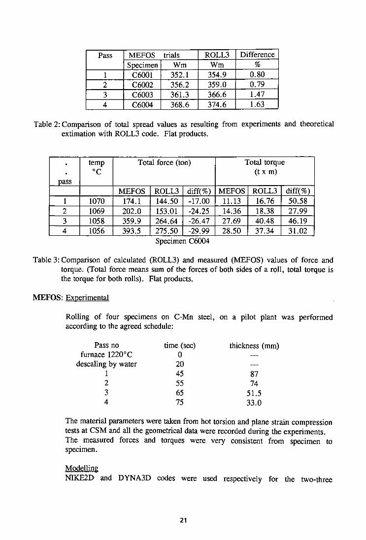
dimensional simulation. A very good agreement between calculated (DYNA3D) and experimental results was recorded. No trial and error procedure was used to find a friction coefficient suitable to provide a calculated contact force very close to the measured one.
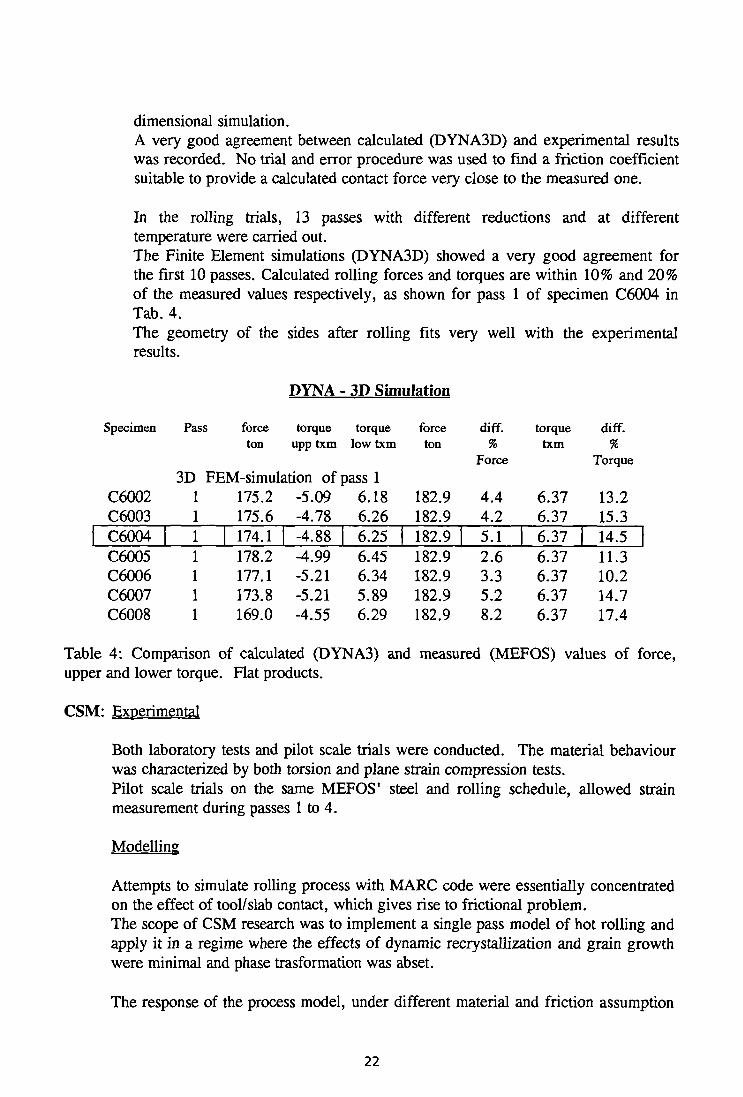
In the rolling trials, 13 passes with different reductions and at different temperature were carried out. The Finite Element simulations (DYNA3D) showed a very good agreement for the first 10 passes. Calculated rolling forces and torques are within 10% and 20% of the measured values respectively, as shown for pass 1 of specimen C6004 in Tab. 4. The geometry of the sides after rolling fits very well with the experimental results.
PYNA - 3D Simulation
Specimen
C6002 C6003 C6004 C6005 C6006 C6007 C6008
Pass force ton
torque upp txm
3D FEM-simulation of 1 1 1 1 1 1 1
175.2 175.6 174.1 178.2 177.1 173.8 169.0
-5.09 -4.78 -4.88 -4.99 -5.21 -5.21 -4.55
torque low txm
>ass 1 6.18 6.26 6.25 6.45 6.34 5.89 6.29
force ton
182.9 182.9 182.9 182.9 182.9 182.9 182.9
diff. %
Force
4.4 4.2 5.1 2.6 3.3 5.2 8.2
torque txm
6.37 6.37 6.37 6.37 6.37 6.37 6.37
diff. %
Torque
13.2 15.3 14.5 11.3 10.2 14.7 17.4
Table 4: Comparison of calculated (DYNA3) and measured (MEFOS) values of force, upper and lower torque. Flat products.
CSM: Experimental
Both laboratory tests and pilot scale trials were conducted. The material behaviour was characterized by both torsion and plane strain compression tests. Pilot scale trials on the same MEFOS1 steel and rolling schedule, allowed strain measurement during passes 1 to 4.
Modelling
Attempts to simulate rolling process with MARC code were essentially concentrated on the effect of tool/slab contact, which gives rise to frictional problem. The scope of CSM research was to implement a single pass model of hot rolling and apply it in a regime where the effects of dynamic recrystallization and grain growth were minimal and phase trasformation was abset.
The response of the process model, under different material and friction assumption
22

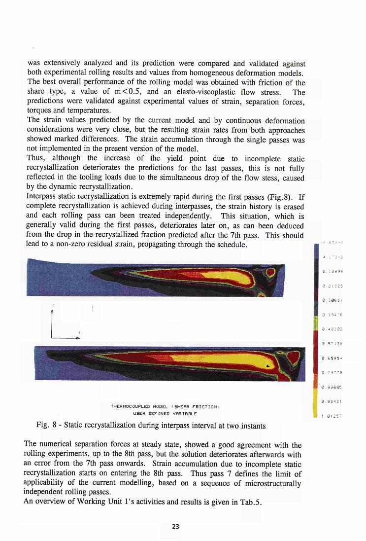
was extensively analyzed and its prediction were compared and validated against both experimental rolling results and values from homogeneous deformation models. The best overall performance of the rolling model was obtained with friction of the share type, a value of m<0.5, and an elasto-viscoplastic flow stress. The predictions were validated against experimental values of strain, separation forces, torques and temperatures. The strain values predicted by the current model and by continuous deformation considerations were very close, but the resulting strain rates from both approaches showed marked differences. The strain accumulation through the single passes was not implemented in the present version of the model. Thus, although the increase of the yield point due to incomplete static recrystallization deteriorates the predictions for the last passes, this is not fully reflected in the tooling loads due to the simultaneous drop of the flow stess, caused by the dynamic recrystallization. Interpass static recrystallization is extremely rapid during the first passes (Fig. 8). If complete recrystallization is achieved during interpasses, the strain history is erased and each rolling pass can been treated independently. This situation, which is generally valid during the first passes, deteriorates later on, as can been deduced from the drop in the recrystallized fraction predicted after the 7th pass. This should lead to a non-zero residual strain, propagating through the schedule.
3 2 13 25
3 . 3 06 5 I
0 . 3 9*1 "6
9 . -4 3 3 32
. 5 - 1 3 8
3 6 5 3 5 4
3 . 7 4 " 3
0 . 3 3 6 0 5
THERMOCOUPLES MODEL 'SHEAR F R I C T I O N -
USER DEFINED VARIABLE
Fig. 8 - Static recrystallization during interpass interval at two instants
The numerical separation forces at steady state, showed a good agreement with the rolling experiments, up to the 8th pass, but the solution deteriorates afterwards with an error from the 7th pass onwards. Strain accumulation due to incomplete static recrystallization starts on entering the 8th pass. Thus pass 7 defines the limit of applicability of the current modelling, based on a sequence of microstructurally independent rolling passes. An overview of Working Unit l's activities and results is given in Tab.5.
a . 9 2 - 4 3 !
1 . 0 I 2 S 7
23

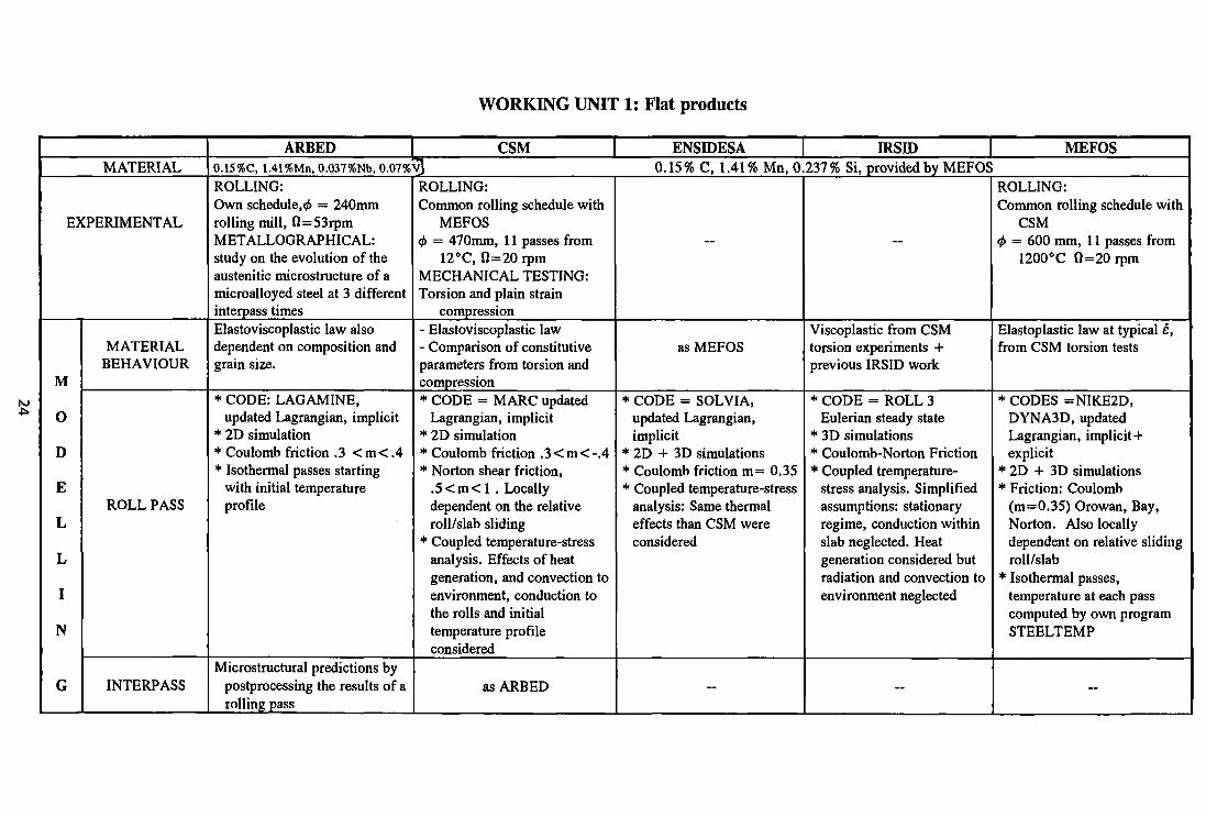
WORKING UNIT 1: Flat products
M *»
MATERIAL
EXPERIMENTAL
M
O
D
E
L
L
I
N
G
MATERIAL BEHAVIOUR
ROLL PASS
INTERPASS
ARBED CSM 0.15%C, 1.41%Mn, 0.037%Nb, 0.07%yJ ROLLING: Own schedule,^ = 240mm rolling mill, fi=53rpm METALLOGRAPHICAL: study on the evolution of the austenitic microstructure of a microalloyed steel at 3 different interpass times Elastoviscoplastic law also dependent on composition and grain size.
* CODE: LAGAMINE, updated Lagrangian, implicit
* 2D simulation * Coulomb friction .3 < m < . 4 * Isothermal passes starting
with initial temperature profile
Microstructural predictions by postprocessing the results of a rolling pass
ROLLING: Common rolling schedule with
MEFOS <f> = 470mm, 11 passes from
12°C, 0=20 rpm MECHANICAL TESTING: Torsion and plain strain
compression - Elastoviscoplastic law - Comparison of constitutive parameters from torsion and compression * CODE = MARC updated
Lagrangian, implicit * 2D simulation * Coulomb friction . 3<m<- .4 * Norton shear friction,
. 5 < m < l . Locally dependent on the relative roll/slab sliding
* Coupled temperature-stress analysis. Effects of heat generation, and convection to environment, conduction to the rolls and initial temperature profile considered
as ARBED
ENSIDESA 1RS1D 0.15% C, 1.41% Mn, 0.237% Si, provided by MEFOS
—
as MEFOS
* CODE = SOLVIA, updated Lagrangian, implicit
* 2D + 3D simulations * Coulomb friction m= 0.35 * Coupled temperature-stress
analysis: Same thermal effects than CSM were considered
—
—
Viscoplastic from CSM torsion experiments + previous IRSID work
* CODE = ROLL 3 Eulerian steady state
* 3D simulations * Coulomb-Norton Friction * Coupled tremperature-
stress analysis. Simplified assumptions: stationary regime, conduction within slab neglected. Heat generation considered but radiation and convection to environment neglected
—
MEFOS
ROLLING: Common rolling schedule with
CSM <f> = 600 mm, 11 passes from
1200°C fi=20rpm
Elastoplastic law at typical e, from CSM torsion tests
* CODES =NIKE2D, DYNA3D, updated Lagrangian, implicit+ explicit
* 2D + 3D simulations * Friction: Coulomb
(m=0.35) Orowan, Bay, Norton. Also locally dependent on relative sliding roll/slab
* Isothermal passes, temperature at each pass computed by own program STEELTEMP
—
U1
EXPERIMENTAL
K E S
u L T S
MODELLING
CONCLUSIONS
Grain size and RX fraction at different quenching times
separation force + temperature + through thickness strain
* Separation force + torque + temperature + lateral spread
* Experimantal work on rolling of conical specimens to assess friction
Benchmark case study, first pass, isothermal analysis, T = 1048°C, <t>T0\\s = 0.6 fl = 20rpm, MEFOS material, torsion data from CSM
* Modelling passes 1 to 11 * Comparison of elastoplastic
and viscoplastic results, first pass
* Modelling passes 1 to 8
* Comparison of results from SOLVIA vs ABAQUS
* Modelling pass 1
* Sensitivity of the results to mesh discretization
* Modelling passes 1 to 11
* Analysis of the schedule accumulating the spread through passes
* Study on performance of implicit vs explicit codes
* Estimation of the flow stress of the scale, for two thickness: 0.04mm and 1.5mm
* Modelling passes 1 to 11 of the common schedule + conical specimens + full scale rolling
* Lateral spread in a single pass, not accumulating through the schedule.
The current modelling, based on a sequence of microstructurally independent rolling passes, provides pood predictions up to pass 7th. with contained errors of 10% in the separation force and 20% in the roll torque respect to the experiments. Tnterpass statir. recrystallization suffers a sharp decline from pass 7th onwards and this results in accumulation of strain through passes, which can reach the threshold level of dynamic recrystallization. This explains the deterioration of the prediction in the last passes of the schedule. The results from the Eulerian Code ROLL3 indicates that lateral spread is very sensitive to mesh and friction. Moreover, the spread accumulated through passes overestimate the experimental values.
4.2) Hot rolling of long products
BS: Experimental
Rolling trials were carried out using 316S31 stainless steel, in an experimental three-high reversing mill. This is a single phase austenitic stainless steel, in which the deformed structure was retained by quenching immediately after rolling. Typical long product sections were rolled, e.g. round/oval, square/oval and round/ cornered square oval. Lateral spread profiles, rolling loads and torques were measured. In the case of round/oval pass, internal strain distribution was assessed, using a metallographic technique, in which the aspect ratios of individual grains of material were measured. Porosity was investigated. Values of relative density for porous, Type 316 stainless steel, produced by continuous casting were obtained experimentally, using a special rig which allowed specimens to be weighted in air and liquid utilizing the Archime-de's principle. The determined value of relative density was used in the model. Flow stress data for porous steel of the above quality were obtained using the Gleeble 1500 termomechanical simulator. The investigated conditions corresponded to reductions of up to 55% at strain rate of 0.5, 1, 5, 10, 15 and 20 sec'1, at temperature of 900 and 1000°C. Measured values of relative density in porous, continuously cast stainless steel, were around 98%. Predictions showed that even with a relative density of 98%, a reduction of 10% by rolling was not sufficient to consolidate the material significantly.
Modelling
PREFECT code, originally developed for flat rolling, was enhanced to make possible consideration of the cross section typical of long products. PREFECT was interfaced with the PATRAN pre- and post-processing package, which should allow to determine free surface boundaries of the non rectangular stock and true roll contact geometry. The original PREFECT model was based on the so-called "flow formulation", in which the material constitutive behaviour was described by a viscoplastic relationship and the analysis was performed in an Eulerian coordinate system.
Sticking friction at the roll/metal interface was assumed.
A major problem with the flow formulation was the difficulty in determining the boundaries of the free surfaces, and the true geometry of contact. Consequently an updated Eulerian version of the PREFECT was developed, to model the rolling of long product sections in grooved passes.
A simple mixed friction model, based on Coulomb's friction model, and procedures for calculating hydrostatic and true stress components were also incorporated.
The updated Eulerian model was applied to rolling in round/oval, and square/oval passes.
26
Effects of temperature and deformation coupling were investigated, in order to enable application to the case of asymmetric rolling, particularly those involving non-uniform temperature distribution.
Further developments were made on the model to set up a framework within which porosity could be investigated. The model developed for porosity uses appropriate constitutive equations rather than cavities in the mesh, and allows examination of porosity, either extensive throughout the workpiece or localised near the centre. In the absence of appropriate data for stainless steel the model was tested, initially, using constitutive information for porous copper having a relative density of 85%. The rolling of both square and tall thin workpieces to various reductions was considered.
In applying the porosity model to the rolling of a square specimen with 20% reduction it was found that the velocity in the leading zone was smaller for a porous than for a non porous material. For an extensively porous metal, the greatest consolidation, as measured by the increase in relative density, was found near the surface of contact; whereas, for the porosity localised near the centre, the consolidation was also concentrated there. Strain distributions with centrally localised porosity were concentrated near the centre, whereas almost uniform distributions of strain were found for the homogeneus metal. Complete consolidation could be achieved in square and tall thin workpiece only with a reduction of about 20%.
The measured internal strain distributions were compared with predictions using PREFECT FE model.
For rolling a round/oval pass the PREFECT updated Eulerian code with sticking friction, understimated the vertical strain at the stock centre by 24% whereas near the rolled and free surfaces a good agreement between measured and predicted values was recorded.
IRSID: Experimental
None
Modelling
After several meshing tests, the four experimental passes done by BS (round/oval, oval/round, square with sharp angles/oval and square with rounded angles/oval) was simulated using ROLL3 code, according to the BS rolling schedule.
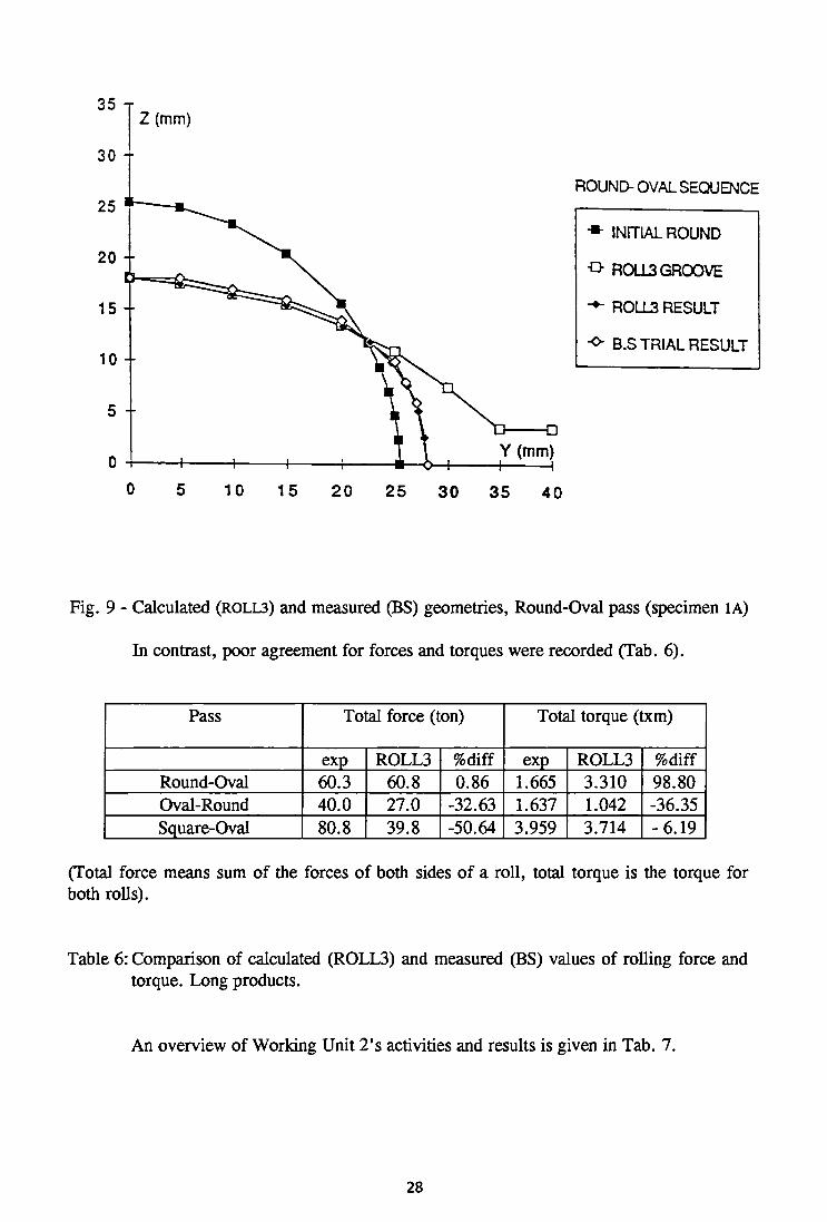
The computations were made with no thermo-mechanical coupling and led to exit profiles corresponding well to the measurements. The predicted and measured strain components were compared in the case of the round/oval pass. Exept for the vertical component over-evaluated of 9% by the code, the two other components were in very good agreement (Fig. 9).
27
35 T Z (mm)
ROUND- OVAL SEQUENCE
* INITIAL ROUND
-D- ROLL3 GROOVE
•+■ ROLL3 RESULT
"0- B.S TRIAL RESULT
10 15 20 25 30 35 40
Fig. 9 - Calculated (ROLL3) and measured (BS) geometries, Round-Oval pass (specimen 1A)
In contrast, poor agreement for forces and torques were recorded (Tab. 6).
Pass
Round-Oval Oval-Round Square-Oval
Total force (ton)
exp 60.3 40.0 80.8
ROLL3 60.8 27.0 39.8
%diff 0.86
-32.63 -50.64
Total torque (txm)
exp 1.665 1.637 3.959
ROLL3 3.310 1.042 3.714
%diff 98.80 -36.35 -6.19
(Total force means sum of the forces of both sides of a roll, total torque is the torque for both rolls).
Table 6: Comparison of calculated (ROLL3) and measured (BS) values of rolling force and torque. Long products.
An overview of Working Unit 2's activities and results is given in Tab. 7.
28
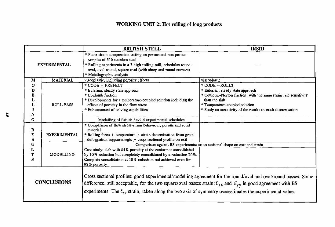
WORKING UNIT 2: Hot rolling of long products
EXPERIMENTAL
M 0 D E L L I N G
R E S
u L T S
MATERIAL
ROLL PASS
EXPERIMENTAL
MODELLING
CONCLUSIONS
BRITISH STEEL * Plane strain compression testing on porous and non porous
samples of 316 stainless steel * Rolling experiments in a 3-high rolling mill, schedules round-
oval, oval-round, square-oval (with sharp and round corners) * Metallographic analysis viscoplastic, including porosity effects * CODE = PREFECT * Eulerian, steady state approach * Coulomb friction * Developments for a temperature-coupled solution including the
effects of porosity in the flow stress * Enhancement of solving capabilities
Modelling of British Steel 4 experimental schedules * Comparison of flow stress-strain behaviour, porous and solid
material * Rolling force + temperature + strain determination from grain
deformation measurements + cross sectional profile on exit
IRSID
._
viscoplastic * CODE =ROLL3 * Eulerian, steady state approach * Coulomb-Norton friction, with the same strain rate sensitivity
than the slab * Temperature-coupled solution * Study on sensitivity of the results to mesh discretization
Comparison against BS experiments: cross sectional shape on exit and strain Case study: slab with 85 % porosity at the center not consolidated by 10% reduction but completely consolidated by a reduction 20%. Complete consolidation at 10% reduction not achieved even for 98 % porosity
Cross sectional profiles: good experimental/modelling agreement for the round/oval and oval/round passes. Some difference, still acceptable, for the two square/oval passes strain: 6XX and £yV in good agreement with BS experiments. The £zz strain, taken along the two axis of symmetry overestimates the experimental value.
4.3) Hot rolling of special sections
IBF-RWTH: Experimental
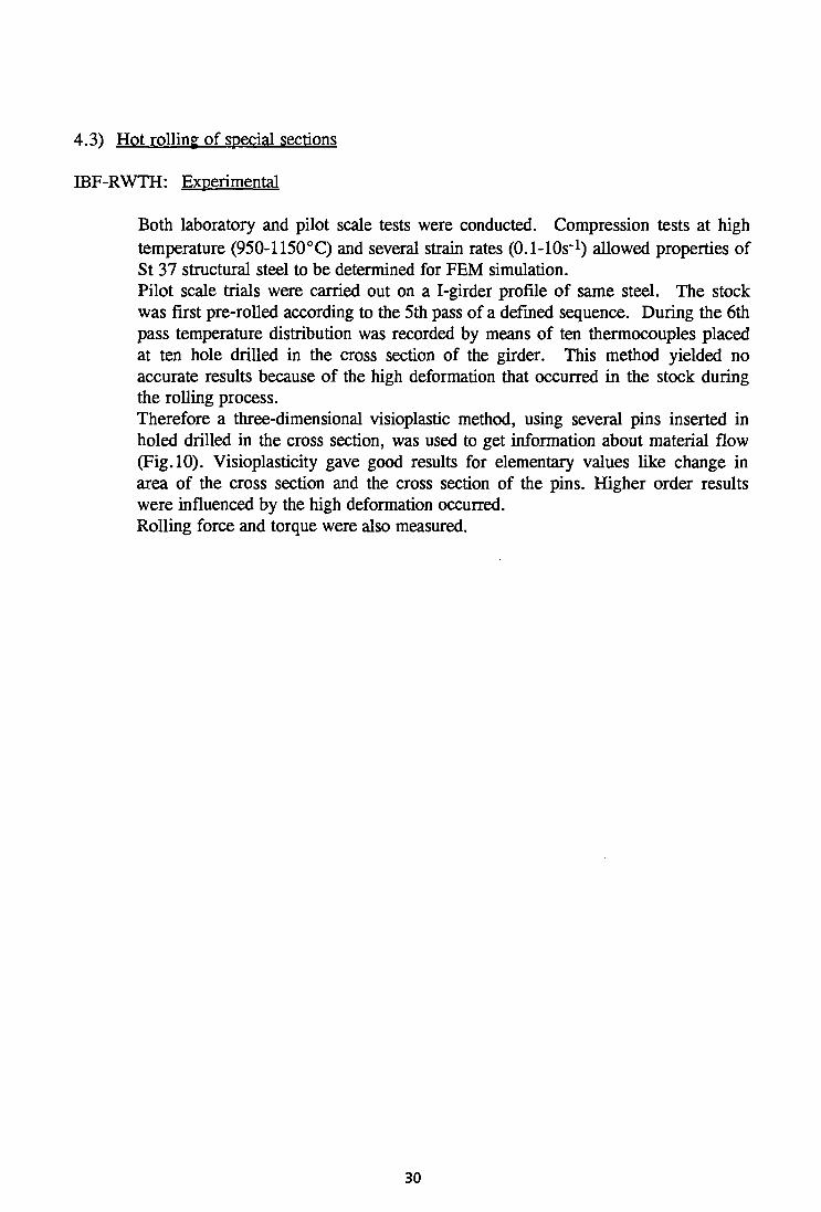
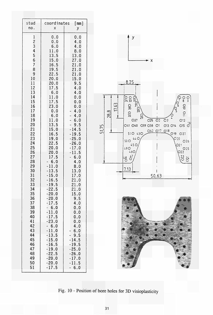
Both laboratory and pilot scale tests were conducted. Compression tests at high temperature (950-1150°C) and several strain rates (0.1-lOs"1) allowed properties of St 37 structural steel to be determined for FEM simulation. Pilot scale trials were carried out on a I-girder profile of same steel. The stock was first pre-rolled according to the 5th pass of a defined sequence. During the 6th pass temperature distribution was recorded by means of ten thermocouples placed at ten hole drilled in the cross section of the girder. This method yielded no accurate results because of the high deformation that occurred in the stock during the rolling process. Therefore a three-dimensional visioplastic method, using several pins inserted in holed drilled in the cross section, was used to get information about material flow (Fig. 10). Visioplasticity gave good results for elementary values like change in area of the cross section and the cross section of the pins. Higher order results were influenced by the high deformation occurred. Rolling force and torque were also measured.
30
stud no. 1 2 3 4 5 6 7 8 9 10 11 12 13 14 15 16 17 18 19 20 21 22 23 24 25 26 27 28 29 30 31 32 33 34 35 36 37 38 39 40 41 42 43 44 45 46 47 48 49 50 51
coordinates [mm] X
0.0 0.0 6.0 11.0 13.5 15.0 16.5 19.5 22.5 20.0 20.0 17.5 6.0 11.0 17.5 23.0 0.0 6.0 11.0 13.5 15.0 16.5 19.0 22.5 20.0 20.0 17.5 - 6.0 -11.0 -13.5 -15.0 -16.5 -19.5 -22.5 -20.0 -20.0 -17.5 - 6.0 -11.0 -17.5 -23.0 - 6.0 -11.0 -13.5 -15.0 -16.5 -19.0 -22.5 -20.0 -20.0 -17.5
y 0.0 4.0 4.0 8.0 13.0 27.0 21.0 21.0 21.0 15.0 9.5 4.0 4.0 0.0 0.0 0.0
- 4.0 - 4.0 - 6.0 - 9.5 -14.5 -19.5 -25.0 -26.0 -17.0 -11.5 - 6.0 4.0 8.0 13.0 17.0 21.0 21.0 21.0 15.0 9.5 4.0 0.0 0.0 0.0 0.0 4.0
- 6.0 - 9.5 -14.5 -19.5 -25.0 -26.0 -17.0 -11.5 - 6.0
. , 8 , 2 5 , .
Fig. 10 - Position of bore holes for 3D visioplasticity
31
Modelling
LARSTRAN/SHAPE code was used for the hot rolling simulation of the INP*80 girder pass 5.
For the hot rolling simulation the following algorithms and element type were adopted:
- Linear isoparametric 8-mode hexaedrical elements based on a rigid-plastic constitutive law, according to the Levy-v. Mises. Volume constancy was incorporated in the element formulation through a penalty factor.
- Thermal coupling was allowed for by an iterative solution of the mechanical and thermal problem. Heat trasmission to the ambient air was described by radiation, according to the Stefan-Boltzman law; heat transmission to the rolls was described by thermal conduction with a heat transmission coefficient. In both cases a constant ambient temperature was assumed. Initially, therefore thermal conduction in the roll was taken into account.
Comparison between experimental and predicted values showed that LARSTRAN/SHAPE code was generally appropriate to get exact information about material flow and temperature distributions, as well as forces and compressed length during rolling.
IRSID: Experimental None
Modelling
The roughing pass of a INP80 beam produced IBF was simulated, using ROLL3 code. The computations made without coupling gave strain values overestimated with respect to measurements, whilst strain variations recorded in the exit sector were similar. The meshing possibilities of the code were better adopted to flat and long products. For special cross sections the meshing possibilities must be increased. An overview of Working Unit 3's activities and results is given in Tab. 8.
32
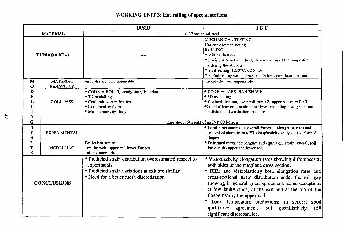
WORKING UNIT 3: Hot rolling of special sections
MATERIAL
EXPERIMENTAL
M 0 D E L L I N G R E S L T S
MATERIAL BEHAVIOUR
ROLL PASS
EXPERIMENTAL
MODELLING
CONCLUSIONS
IRSID I B F St37 structural steel
—
viscoplastic, uncomprensible
* CODE = ROLL3, steady state, Eulerian * 3D modelling * Coulomb-Norton friction * Isothermal analysis * Mesh sensitivity study
MECHANICAL TESTING: Hot compression testing ROLLING: * Mill calibration * Preliminary test with lead, determination of the pre-profile
entering the 5th pass * Steel rolling, 1250°C, 0.15 m/s * Partial rolling with copper inserts for strain determination viscoplastic, uncompressible
* CODE = LARSTRAN/SHAPE * 3D modelling * Coulomb friction,lower roll m=0.2, upper roll m = 0.45 ♦Coupled temperature-stress analysis, including heat generation,
radiation and conduction to the rolls
Case study: 5th pass of an INP 80 I-girder
Equivalent strain: - on the web, upper and lower flanges - at the outer side * Predicted strain distribution overestimated respect to
experiments * Predicted strain variations at exit are similar * Need for a better mesh discretization
* Local temperatures + overall forces + elongation rates and equivalent strain from a 3D visioplasticity analysis + deformed shapes
* Deformed mesh, temperature and equivalent strain, overall roll force at the upper and lower roll
* Visioplasticity elongation rates showing differences at both sides of the midplane cross section.
* FEM and visioplasticity both elongation rates and cross-sectional strain distribution under the roll gap showing in general good agreement, some exceptions at few faulty studs, at the exit and at the top of the flange nearby the upper roll
* Local temperature predictions: in general good qualitative agreement, but quantitatively still significant discrepancies.
5. DEEP-DRAWING OF COATED STEEL SHEETS
To the design of metal-working processes, it is necessary to define the factors that can limit plastic deformation. These may be broadly classified into two types:
instability: which is the creation of undesiderable types of deformation due to small irregularities in the metal or in the load application;
fracture: which is the creation of new surfaces.
Instabilities are associated either with compressive stresses (so called buckling) or with tensile stresses (so called necking). Their appearance is a very complex problem still not completely understood in the case of coated materials.
However, it can be said that factors which tend to spread plastic deformation reduce the likelihood of instability. These may be material properties such as work hardening, or they may be mechanical design factors such as shape and method of load application.
Fracture is associated with the attainment of some critical tensile stress within the metal. This is why in metal working the amount of plastic deformation is generally enhanced by using compressive rather than tensile methods.
In addition to avoiding instability and fracture, a metal working operation may be designed to minimize forces or to increase efficiency.
Forming forces are minimized in tensile-compressive operations. Efficiency is enhanced by minimizing tool surface friction and by avoiding redundant work; that is work that does not contribute to the final shape. Redundant work is quite difficult to avoid completely, but can be kept small by lubrication and die shaping.
Other factors which might be important in metal-working operations are the particular property of cold rolled sheets of possessing directional mechanical properties: i.e. anisotropy, and the frictional conditions between the worked material and the forming tools.
All effects of the above factors on the deep-drawing operations are amplified by the presence of coating layers. Due to the different mechanical properties, anisotropy, and to the quality of the adhesion with the substrates, the coating layers might radically change their basic properties and require a radical change into the design of the cold-working operations.
CRM: Experimental
Several laboratory tests under mono and biaxial state of stresses were conducted on four selected coated steel sheets, in particular Wide Tensile Test (width: 200 mm, gauge length: 30 mm) and Bulging Test (application of an equibiaxial straining on a flat specimen). Aim of the tests was the measurement of material coefficients needed to implement in a FEM-code the CRM's plasticity model 3G, which describes the plastic deformation
34
of steels in terms of a superimposition of shear strains occurring in planes at 45° with respect to the principal stresses. In addition friction coefficients have been determined with both low and high viscosity oil to explore the effect of the cross head speed and to achieve conditions very close to the ones prevailing in the experimental set-up for deep-drawing.
Modelling
Implementation of its own plasticity model into the ABAQUS code. Having solved some problems related to the numerical discretization of the derivatives which affected the convergence, a successful simulation was conducted of deep-drawing process.
NTU: Experimental
Study of flow mechanisms in stretching circular disks and deep-drawing of both circular and rectangular shapes. Experiments include visual observation of defect generation, measurement of grid displacement and distortion, pressures and forces evaluation. The overall set of experiments carried on coated steel sheets, was aimed at gaining information concerning flow rule, anisotropy and friction coefficients in presence of different coating layers.
Modelling
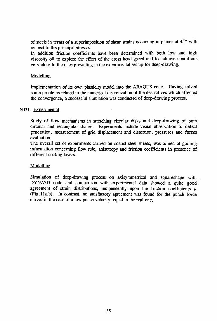
Simulation of deep-drawing process on axisymmetrical and squareshape with DYNA3D code and comparison with experimental data showed a quite good agreement of strain distributions, indipendently upon the friction coefficients /x (Fig.lla,b). In contrast, no satisfactory agreement was found for the punch force curve, in the case of a low punch velocity, equal to the real one.
35
0.20
era i—• t—*
8 3 IS. J? O CD 3
«*> 2 .
tb g
«■ o •-h BL
a, S. 2 . n>
3 E en
O c a
a.
<
B. & EL
I
0.16
§0.12
CO
T3 0.08 a a:
0.04 -
0.00
h= 1 2.6 mm * * * * * Experiment ooooo | j =0 ,05 FEM D_D_D_OjD |J = 0 . 1 0 FEM ***** | j =0 .13 FEM
coordinate (mm) 60
h=10mm ,20mm,
Figl lb - Comparison of theoretical and experimental curve of radial strain VS initial radial coordinate, at different friction coefficients
SIMR: Experimental
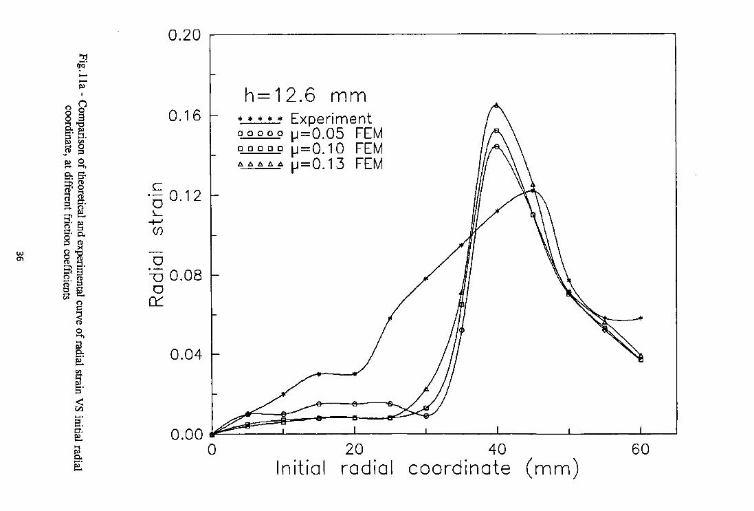
Rectangular shaped components were pressed from four zinc coated sheet steels. Two of the steels were hot dip galvanized and two were electrogalvanized. For each coating type one steel had a r-value close to unity and one a higher r-value. Pressing was performed with a corrosion protective oil and with a drawing oil. Both rectangular shaped blanks and blanks with cut corners were tested. One blank holder force was used for all pressings (Fig. 12).
/ \
^
€v\> "J!' ■IIIIIIIIIIIIIIII iiiiiiiiiiiimiiinimmii •.'•♦S -;•;..", "'•umiiinmiiiiHiiiiiiiii iiiiiniiiiiiu" < ■ ■•.V.-V -;- "".'.'.'.'Luiiiiiiiiniui iiiiiiiiiiiii i iiiiiiiiiiii.!
1.1.'.""--:V
■ |.i.' I I I I I I l l l l l l l l I I I I I I I I l I I l I I I I I I I I I I I I l l l l l l l l l l i ' ,
^ s
ISiiiiiiiisiiiiiiSSSi!!:!!!!^
v V Fig. 12 - Mesh for blank with cut corners after pressing to 20 mm depth
37
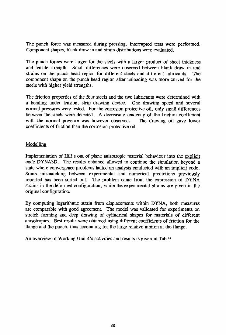
The punch force was measured during pressing. Interrupted tests were performed. Component shapes, blank draw in and strain distributions were evaluated.
The punch forces were larger for the steels with a larger product of sheet thickness and tensile strength. Small differences were observed between blank draw in and strains on the punch head region for different steels and different lubricants. The component shape on the punch head region after unloading was more curved for the steels with higher yield strengths.
The friction properties of the four steels and the two lubricants were determined with a bending under tension, strip drawing device. One drawing speed and several normal pressures were tested. For the corrosion protective oil, only small differences between the steels were detected. A decreasing tendency of the friction coefficient with the normal pressure was however observed. The drawing oil gave lower coefficients of friction than the corrosion protective oil.
Modelling
Implementation of Hill's out of plane anisotropic material behaviour into the explicit code DYNA3D. The results obtained allowed to continue the simulation beyond a state where convergence problems halted an analysis conducted with an implicit code. Some mismatching between experimental and numerical predictions previously reported has been sorted out. The problem came from the expression of DYNA strains in the deformed configuration, while the experimental strains are given in the original configuration.
By computing logarithmic strain from displacements within DYNA, both measures are comparable with good agreement. The model was validated for experiments on stretch forming and deep drawing of cylindrical shapes for materials of different anisotropies. Best results were obtained using different coefficients of friction for the flange and the punch, thus accounting for the large relative motion at the flange.
An overview of Working Unit 4's activities and results is given in Tab.9.
38
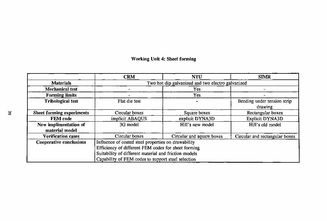
Working Unit 4: Sheet forming
CO 1 0
Materials Mechanical test Forming limits
Tribological test
Sheet forming experiments FEM code
New implimentation of material model
Verification cases Cooperative conclusions
CRM NTU Two hoi
--
Flat die test
Circular boxes implicit ABAQUS
3G model
Circular boxes
SEvIR k dip galvanized and two electro galvanized
Yes Yes
-
Square boxes explicit DYNA3D Hill's new model
Circular and square boxes
--
Bending under tension strip drawing
Rectangular boxes Explicit DYNA3D Hill's old model
Circular and rectangular boxes Influence of coated steel properties on drawability Efficiency of different FEM codes for sheet forming Suitability of different material and friction models Capability of FEM codes to support steel selection
6. CONCLUSIONS
- FEM techniques are able to provide extensive information about material flow, strain and temperature distributions, which are key to microstructural development.
- Updated Lagrangian formulation, provides good agreement between experimental and predicted values (temperature and strain distributions, rolling forces and torques)
Implicit codes consume more computing time than the explicit codes but the results are similar.
- Steady state Eulerian codes are also able to provide good results, with some difficulties in free surfaces calculation. Main advantage is their reduced computing time.
-The main difficulty is using the FEM is to obtain all necessary information about the material behaviour, both mechanical and thermal. The more accurate the material properties are described, the more accurate the results will be. Indeed algorithms used in FEM to describe e.g. heat loss by radiation, need parameters which show a strong dependency upon a set of variables. These parameters are not exactly known, but only deducible from the experience.
-The present investigation has proved that to achieve a strict control of the rolling operations on whatever geometry, the interpass time (during which static recrystallization occurs) must be compatible with the recrystallization half-time, in such a way to avoid dynamic recrystallization.
- Regarding deep-drawing operations, to achieve a closer agreement with experiments a very sophisticated model for description of constitutive material behaviour is necessary. The 3G model proposed by CRM, involving microplasticity criteria and dislocation kinetics, allows to get satisfactory results.
- In its present state of development the FEM is very far from a reliable on-line application at industrial scale.
40


® CORDIS
The Community Research and Development Information Service
Your European R&D Information Source CORDIS represents a central source of information crucial for any organisation - be it industry, small and medium-sized enterprises, research organisations or universities - wishing to participate in the exploitation of research results, participate in EU funded science and technology programmes and/or seek partnerships.
CORDIS makes information available to the public through a collection of databases. The databases cover research programmes and projects from their preparatory stages through to their execution and final publication of results. A daily news service provides up-to-date information on EU research activities including calls for proposals, events, publications and tenders as well as progress and results of research and development programmes. A partner search facility allows users to register their own details on the database as well as search for potential partners. Other databases cover Commission documents, contact information and relevant publications as well as acronyms and abbreviations.
By becoming a user of CORDIS you have the possibility to: • Identify opportunities to manufacture and market new products • Identify partnerships for research and development • Identify major players in research projects • Review research completed and in progress in areas of your interest
The databases - nine in total - are accessible on-line free of charge. As a user-friendly aid for on-line searching, Watch-CORDIS, a Windows-based interface, is available on request. The databases are also available on a CD-ROM. The current databases are:
News (English, German and French version) - Results -Partners - Projects - Programmes - Publications -
Acronyms - Comdocuments - Contacts
CORDIS on World Wide Web The CORDIS service was extended in September 1994 to include the CORDIS World Wide Web (WWW) server on Internet. This service provides information on CORDIS and the CORDIS databases, various software products, which can be downloaded (including the above mentioned Watch-CORDIS) and the possibility of downloading full text documents including the work programmes and information packages for all the research programmes in the Fourth Framework and calls for proposals.
The CORDIS WWW service can be accessed on the Internet using browser software (e.g. Netscape) and the address is: http://www.cordis.lu/ The CORDIS News database can be accessed through the WWW.
Contact details for further Information If you would like further information on the CORDIS services, publications and products, please contact the CORDIS Help Desk:
CORDIS Customer Service Telephone: +352-401162-240 B.P. 2373 Fax: +352-401162-248 L-1023 Luxembourg E-mail: [email protected]
WWW: http://www.cordis.lu/


European Commission
EUR 15803 — Mechanical working (rolling mills) Application of finite elements method in hot rolling and deep drawing
M. Mirabile, J. Bianchi, R. Buenten, P. Buessler, P. Ingham, M. Mamalis, G. Monfort, F. Requejo, P. Turpel
Luxembourg: Office for Official Publications of the European Communities
1997 — 40 pp. — 21.0 x 29.7 cm
Technical steel research series
ISBN 92-828-0744-4
Price (excluding VAT) in Luxembourg: ECU 7
The results of this wide-ranging, multi-partner research project about finite modelling techniques have demonstrated that:
• FEM techniques are able to provide extensive information about material flow, strain and temperature distribution;
• updated Lagrangian formulation provides good agreement between experimental and predicted values (temperature and strain distributions, rolling forces and torques);
• steady-state Eulerian codes are also able to provide good results;
• the main difficulty in using FEM is to obtain all the necessary information about material behaviour, both mechanical and thermal;
• this project has proved that to achieve strict control of rolling operations, regardless of geometry, the interpass time (during which static recrystallization occurs) must be compatible with the recrystallization half time, in order to avoid dynamic recrystallization;
• to achieve closer agreement in deep-drawing operations a very sophisticated model is required which is able to describe the material behaviour;
• in its present state of development, FEM is far from being a reliable online application at industrial scale.

Venta • Salg • Verkauf • Πωλήσεις • Sales • Vente • Vendita • Verkoop • Venda • Myynti • Försäljning
RFLGIQUE/BELGIE
Monlteur belge/Belglsch Staatsblad Rue de Louvain 40-42/ Leuvenseweg 40-42 B-1000 Bruxelles/Brussel Tel. (32-2) 552 22 11 Fax (32-2) 51101 84
Jean Da Lannoy Avenue du Roi 202/ Koningslaan 202 B-1060 Bruxelles/Brussel Tel. (32-2) 538 51 69 Fax (32-2) 538 08 41 E-mail: [email protected]
Libralrle europeenne/Europese Boekhandel Rue de la Loi 244/ Wetstraat 244 B-1040 Bruxelles/Brussel Tel. (32-2) 295 26 39 Fax 32-2 735 08 60
DANMARK
J. H. Schultz Information A/S Herstedvang 10-12 DK-2620 Albertslund Tlf. (45) 43 63 23 00 Fax (45) 43 63 19 69 E-mail: [email protected] URL: www.schultz.dk
DEUTSCHLAND
Bundesanzelger Verlag Breite Straße 78-80 Postfach10 05 34 D-50667 Köln Tel. (49-221)20 29-0 Fax 49-221)20 29 278
GREECE/ΕΛΛΑΔΑ
G.C. Eleftheroudakls SA International Bookstore Panepistimiou 17. GR-105 64 Athens Tel. (30-1)331 41 80/1/2/3 Fax (30-1) 323 98 21 E-mail: [email protected]
ESPANA
Mundl Prensa Libras, SA Castelld. 37 E-28001 Madrid Tel. (34-1) 431 33 99/431 32 22 Fax (34-1) 575 39 98 E-mail: [email protected] URL: www.tsai.es/mprensa
Boletin Oficlal del Estado Trafalgar, 27-29 E-28071 Madrid Tel. (34-1) 538 22 95 (Libras)/
384 17 15 (Suscripciones) Fax (34-1) 538 23 49 (Libras)/
384 17 14 (Suscripciones) URL: www.boe.es
Mundl Prensa Barcelona Consell de Cent, 391 E-08009 Barcelona Tel. (34-3) 488 34 92 Fax (34-3 487 76 59
FRANCE
Journal official Service des publications des CE 26, rue Desaix F-75727 Paris Cedex 15 Tel. (33-1)40 58 77 01/31 Fax (33-1) 40 58 77 00
IRELAND
Government Suppliea Agency Publications Section 4-5 Harcourt Road Dublin 2 Tel. (353-1)66131 11 Fax (353-1) 475 27 60
ITALIA
Llcosa SpA Via Duca dl Calabria. 1/1 Casella postale 552 1-50125 Firenze Tel. (39-55)64 5415 Fax (39-55) 64 12 57 E-mail: [email protected] URL: icl382.cilea.itA/irtual_IJbrary/blbliot/vetrina/ licosami.htm
GRAND-DUCHE DE LUXEMBOURG
Messagaries du livre Sari 5, rue Raiffeisen L-2411 Luxembourg Tel. (352)4010 20 Fax (352) 490 661 E-mail: [email protected]
Abonnements:
Messagerles Paul Kraua 11, rue Christophe Plantin L-2339 Luxembourg Tel. (352) 499 88 88 Fax (352) 499 888 444 E-mail: [email protected] URL: www.mpk.lu
NEDERLAND
SDU Servlcacentrum Ultgevera Christoffel Plantijnstraat 2 Postbus 20014 2500 EA 's-Gravenhage Tel. (31-70)378 98 80 Fax (31-70) 378 97 83 E-mail: [email protected] URL: www.sdu.nl.
OSTERREICH
Manz'sche Verlags- und Unlversltats-buchhandlung Gmbh Siebenbrunnengasse 21 Postfach 1 A-1050Wien Tel. (43-1)53 161 334/340 Fax (43-1) 53 161 339 E-mail: [email protected] URL: www.austria.EU. net:81/manz
PORTUGAL
Imprensa Naclonal-Casa da Moeda, EP Rua Marquês de Sa da Bandeira, 16 A P-105i Lisboa Codex Tel. (351-1)353 03 99 Fax (351-1) 353 02 94/384 01 32
Diatribuidora de Llvros Bertrand Ld.a
Rua das Terras dos Vales, 4 A Apartado 60037 P-2701 Amadora Codex Tel. (351-1) 495 90 50/495 87 87 Fax 351-1 496 02 55
SUOMI/FINLAND
Akateeminen Klrjakauppa / Akademiska Bokhandeln Pohjoisesplanadi 39/ Norra esplanaden 39 PL/PB128 FIN-00101 Helsinki/Helsingfors Tel. (358-9)121 41 Fax (358-9) 121 44 35 E-mail: [email protected] URL: booknel.cuHnet.fi/aka/index.htm
SVERIGE
BTJAB Traktorvagen 11 PO Box 200 S-22100Lund Tel. (46-46)18 00 00 Fax (46-46) 18 01 25 E-mail: [email protected] URL: www.btj.se/media/eu
UNITED KINGDOM
The Stationery Office Ltd (Agency Section) 51, Nine Elms Lane London SW8 5DR Tel. (44-171)873 9090 Fax (44-171) 873 8463 URL: www.the-stationery-office.co.uk
ICELAND
Bokabud Larusar Blfindal Skólavördustig, 2 IS-101 Reykjavik Tel. (354) 55 15 650 Fax (354) 55 25 560
NORGE
NIC Info A/S Østenjoveien 18 Boks6512Etterstad N-0606 Oslo Tel. (47-22) 97 45 00 Fax 47-22) 97 45 45
SCHWEIZ/SUISSE/SVIZZERA
OSEC Stampfenbachstraße 85 CH-8035 Zurich Tel. (41-1)365 5315 Fax (41-1) 365 54 11 E-mail: [email protected] URL: www.osec.ch
ISRAEL
CESKA REPUBLIKA
NIS CR - prodejna Konviktska 5 CZ-113 57Praha1 Tel. (42-2) 24 22 94 33 Fax (42-2) 24 22 94 33 E-mail: [email protected] URL: www.nis.cz
CYPRUS
Cyprus Chamber Of Commerce _ Industry 38, Grivas Digenis Ave Mail orders: PO Box 1455 CY-1509 Nicosia Tel. (357-2) 44 95 00/46 23 12 Fax (357-2) 361 044 E-mail: [email protected]
MAGYARORSZAG
Euro Info Service Europa Haz Margitsziget PO Box 475 H-1396 Budapest 62 Tel. (36-1)11 16061/11 16216 Fax (36-1) 302 50 35 E-mail: [email protected] URL: www.euroinfo.hu/index.htm
MALTA
Miller Distributors Ltd Malta International Airport PO Box 25 LOA 05 Malta Tel. (356) 66 44 88 Fax (356) 67 67 99
POLSKA
Ars Polona Krakowskie Przedmiescie 7 Skr. pocztowa 1001 PL-00-950 Warszawa Tel. (48-2)2612 01 Fax 48-2 26 62 40
TURKIYE
Dunya Infotel A.S. Istiklal Cad. No: 469 TR-80050 Tunel-lstanbul Tel. (90-212)251 91 96
(90-312 427 02 10 Fax (90-212) 251 91 97
BALGARIJA
Europress-Euromedia Ltd 59, Bid Vitosha BG-1000 Sofia Tel. (359-2) 80 46 41 Fax (359-2) 80 45 41
HRVATSKA
Medlatrade Ltd Pavla Hatza 1 HR-10000 Zagreb Tel. (385-1)43 03 92 Fax (385-1) 44 40 59
ROMANIA
Euromedia Str. G-ralBermelotNr41 RO-70749 Bucuresti Tel. (40-1) 210 44 01/614 06 64 Fax 40-1 210 44 01/312 96 46
SLOVAKIA
Slovenska Technlcka Knlznlca Namestie slobody 19 SLO-81223 Bratislava 1 Tel. (42-7)53 18 364 Fax (42-7) 53 18 364 E-mail: europ@tbb1 .sltk.stuba.sk
SLOVENIA
Gospodarskl Vestnlk Zalozniska skupina d.d. Dunajska cesta 5 SI-1000 Ljubljana . Tel. (386)61 133 03 54 Fax (386) 61 133 91 28 E-mail: [email protected] URL: www.gvestnik.si
R.O.Y. International 17, Shimon Hatarssi Street PO Box 13056 61130TelAvrv Tel. (972-3)54614 23 Fax (972-3) 546 14 42 E-mail: [email protected]
Sub-agent for the Palestinian Authority:
index Information Services PO Box 19502 Jerusalem Tel. (972-2)2716 34 Fax (972-2) 27 12 19
RUSSIA
CCEC 60-letiya Oktyabrya Av. 9 117312 Moscow Tel. (095)135 52 27 Fax (095) 135 52 27
AUSTRALIA
Hunter Publications PO Box 404 3167 Abbotsford, Victoria Tel. (61-3)9417 53 61 Fax (61-3) 9419 71 54
CANADA
Uniquement abonnements/ Subscriptions only:
Renouf Publishing Co. Ltd 1294 Algoma Road K1B 3W8 Ottawa, Ontario Tel. (1-613)741 73 33 Fax (1-613) 741 54 39 E-mail: [email protected] URL: lox.NSTN.Ca/-renoul
EGYPT
The Middle East Observer 41, Sherif Street Cairo Tel. (20-2) 39 39 732 Fax 20-2 39 39 732
JAPAN
PSI-Japan Asahi Sanbancho Plaza #206 7-1 Sanbancho, Chiyoda-ku Tokyo 102 Tel. (81-3)3234 69 21 Fax (81-3) 3234 69 15 E-mail: [email protected] URL: www.psi-japan.com
SOUTH AFRICA
Safto 5th Floor Export House, CNR Maude & West Streets PO Box 782 706 2146 Sandton Tel. (27-11)883 37 37 Fax 27-11 883 65 69
UNITED STATES OF AMERICA
Bernan Associates 4611 -F Assembly Drive MD20706 Lanham Tel. (301 459 2255 (toll tree telephone) Fax (800) 865 3450 (toll free fax) E-mail: [email protected] URL: www.bernan.com
MEXICO
Mundl-Prensa Mexico, SA ds CV RioPanuco, 141 Delegación Cuauhtemoc ME-06500 Mexico DF Tel. (52-5) 553 56 58/60 Fax (52-5) 514 67 99 E-mail: 104164.23compuserve.com
REPUBLIQUE DE COREE
Kyowa Book Company 1 F1. Phyung Hwa Bldg 411 -2 Hap Jeong Dong, Mapo Ku 121-220 Seoul Tel. (82-2) 322 6780/1 Fax (82-2) 322 6782 E-mail: [email protected].
ANDERE LANDER/OTHER COUNTRIES/ AUTRES PAYS
Bitte wenden Sle slch an eln Büro Ihrer Wahl / Please contact the sales office of your choice / Veulilez vous adresser au bureau de vente de votre choix
12/96*

NOTICE TO THE READER
All scientific and technical reports published by the European Commission are announced in the periodical 'euro abstracts', published every two months, and in the R&TD publications database of CORDIS, the Community Research and Development Information Service. For subscription (1 year: ECU 65) please write to the address below.
o
00 o 03
o
Price (excluding VAT) in Luxembourg: ECU 7 ISBN TB-fl2fl-D74i|-i4
• * • OFFICE FOR OFFICIAL PUBLICATIONS * -gj=- * OF THE EUROPEAN COMMUNITIES
* • * L-2985 Luxembourg