Embed Size (px)
Citation preview
Abstract— This paper summarizes the results of design
of new mechanical variable valve actuation (hereafter VVA) systems, developed for high performance motorcycle engines, at University of Napoli Federico II, Department of Industrial Engineering–Section Mechanics and Energy (hereafter DiME).
In addition to a first simple (and limited) system used just as a model for the previous analysis, the work has evolved through three basic steps leading to three types of VVA systems, all mechanical systems (as defined in literature and described later).
The study has been conducted implementing a numerical procedure specifically designed to determine cam profile and kinematic and dynamic characteristics of the whole system, starting from some data (as described in the paper). The model has been validated against the conventional timing system using kinematic simulations. Results of the numerical procedure verify the validity of the VVA systems and particularly a better performance of the last one, in spite of its higher complexity.
Index Terms— Engine Valves, VVA, Variable Valve Actuation, Valve timing
I. INTRODUCTION
he first step of the present work is represented by the study of different VVA mechanical systems in use to
achieve the proposed objectives. The main strategies currently used in automotive field are: timing variation, duration variation, maximum lift variation, combined but not independent variation of timing, duration and lift (reference of the same authors for details [1, 2, 17, 18, 19]. The combined variation of the above parameters could enable several advantages in terms of performance, emissions and consumption. Even if complex, a mechanical system capable to implement this strategy is feasible (an example is the BMW Valvetronic). Generally this solution does not enable to reach independent variation of the three parameters (timing, duration and lift).
DiME is involved in study and manufacturing of new mechanical VVA (Variable Valve Actuation) systems to satisfy demands of weight and size for application on
C. Abagnale is with the Università di Napoli Federico II – Dipartimento
di Ingegneria Industriale – Sez. Meccanica ed Energetica - Italy (corresponding author phone: +393336988088; fax: +390812394165; e-mail: [email protected]).
M. Migliaccio was with the Università di Napoli Federico II – Dipartimento di Ingegneria Industriale – Sez. Meccanica ed Energetica - Italy (e-mail [email protected]).
O. Pennacchia is with the Università di Napoli Federico II – Dipartimento di Ingegneria Industriale – Sez. Meccanica ed Energetica - Italy (e-mail: [email protected]).
modern motorcycle engines designed by MotoMorini. This research aims to the design of a new mechanical VVA system for application on a single-cylinder motorcycle engine, to reach high performance, low specific consumption and low emissions.
II. INNOVATIVE MECHANICAL VVA SYSTEMS
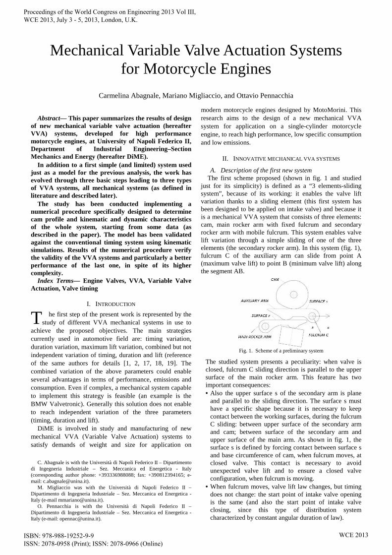
A. Description of the first new system The first scheme proposed (shown in fig. 1 and studied just for its simplicity) is defined as a “3 elements-sliding system”, because of its working: it enables the valve lift variation thanks to a sliding element (this first system has been designed to be applied on intake valve) and because it is a mechanical VVA system that consists of three elements: cam, main rocker arm with fixed fulcrum and secondary rocker arm with mobile fulcrum. This system enables valve lift variation through a simple sliding of one of the three elements (the secondary rocker arm). In this system (fig. 1), fulcrum C of the auxiliary arm can slide from point A (maximum valve lift) to point B (minimum valve lift) along the segment AB.
Fig. 1. Scheme of a preliminary system
The studied system presents a peculiarity: when valve is closed, fulcrum C sliding direction is parallel to the upper surface of the main rocker arm. This feature has two important consequences: • Also the upper surface s of the secondary arm is plane
and parallel to the sliding direction. The surface s must have a specific shape because it is necessary to keep contact between the working surfaces, during the fulcrum C sliding: between upper surface of the secondary arm and cam; between surface of the secondary arm and upper surface of the main arm. As shown in fig. 1, the surface s is defined by forcing contact between surface s and base circumference of cam, when fulcrum moves, at closed valve. This contact is necessary to avoid unexpected valve lift and to ensure a closed valve configuration, when fulcrum is moving.
• When fulcrum moves, valve lift law changes, but timing does not change: the start point of intake valve opening is the same (and also the start point of intake valve closing, since this type of distribution system characterized by constant angular duration of law).
Mechanical Variable Valve Actuation Systems for Motorcycle Engines
Carmelina Abagnale, Mariano Migliaccio, and Ottavio Pennacchia
T
Proceedings of the World Congress on Engineering 2013 Vol III, WCE 2013, July 3 - 5, 2013, London, U.K.
ISBN: 978-988-19252-9-9 ISSN: 2078-0958 (Print); ISSN: 2078-0966 (Online)
WCE 2013
The proposed VVA system 1 has been studied to be actuated by a DC engine: we evaluated to use a DC engine with an average power of 8W and a maximum power of 45W to reach a complete actuation. Performance obtained by this first VVA system in terms of valve lift law consists just in a variation of lift, when fulcrum of the auxiliary arm moves (with a maximum displacement of 20 mm).
B. Mathematical model The study began with the implementation of a numerical
procedure (implemented in a program written by Mathcad) specifically designed to determine (in closed loop) cam profile and kinematic and dynamic characteristics of the whole system, starting from the following input data: rocker arm geometry, relative positions and inertial data of elements, spring stiffness and preloading, camshaft speed and valve lift law. The model was validated against the conventional timing system, using kinematic simulations, as described in this paper.
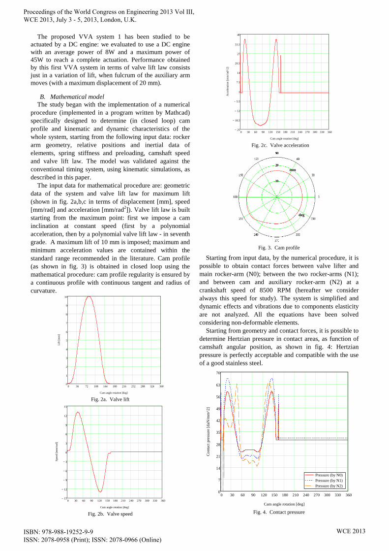
The input data for mathematical procedure are: geometric data of the system and valve lift law for maximum lift (shown in fig. 2a,b,c in terms of displacement [mm], speed [mm/rad] and acceleration [mm/rad2]). Valve lift law is built starting from the maximum point: first we impose a cam inclination at constant speed (first by a polynomial acceleration, then by a polynomial valve lift law - in seventh grade. A maximum lift of 10 mm is imposed; maximum and minimum acceleration values are contained within the standard range recommended in the literature. Cam profile (as shown in fig. 3) is obtained in closed loop using the mathematical procedure: cam profile regularity is ensured by a continuous profile with continuous tangent and radius of curvature.
0 36 72 108 144 180 216 252 288 324 3600
1
2
3
4
5
6
7
8
9
10
Cam angle rotation [deg]
Lift
[mm
]
Fig. 2a. Valve lift
0 30 60 90 120 150 180 210 240 270 300 330 36015−
12−
9−
6−
3−
0
3
6
9
12
15
Cam angle rotation [deg]
Sp
ee
d [m
m/r
ad
]
Fig. 2b. Valve speed
0 30 60 90 120 150 180 210 240 270 300 330 36025−
18.5−
12−
5.5−
1
7.5
14
20.5
27
33.5
40
Cam angle rotation [deg]
Acc
eler
atio
n [m
m/r
ad^2
]
Fig. 2c. Valve acceleration
Fig. 3. Cam profile
Starting from input data, by the numerical procedure, it is possible to obtain contact forces between valve lifter and main rocker-arm (N0); between the two rocker-arms (N1); and between cam and auxiliary rocker-arm (N2) at a crankshaft speed of 8500 RPM (hereafter we consider always this speed for study). The system is simplified and dynamic effects and vibrations due to components elasticity are not analyzed. All the equations have been solved considering non-deformable elements.
Starting from geometry and contact forces, it is possible to determine Hertzian pressure in contact areas, as function of camshaft angular position, as shown in fig. 4: Hertzian pressure is perfectly acceptable and compatible with the use of a good stainless steel.
0 30 60 90 120 150 180 210 240 270 300 330 3600
7
14
21
28
35
42
49
56
63
70
Pressure (by N0)Pressure (by N1)Pressure (by N2)
Cam angle rotation [deg]
Co
nta
ct p
ress
ure
[daN
/mm
^2]
Fig. 4. Contact pressure
mm
deg
Proceedings of the World Congress on Engineering 2013 Vol III, WCE 2013, July 3 - 5, 2013, London, U.K.
ISBN: 978-988-19252-9-9 ISSN: 2078-0958 (Print); ISSN: 2078-0966 (Online)
WCE 2013

The reactions of main and auxiliary arm pivots were calculated (we omit all the results). All the sliding speeds of the system were evaluated to estimate the power dissipated by the mechanism: just for example, fig. 5 shows sliding speed between the arms.
0 30 60 90 120 150 180 210 240 270 300 330 3600.6−
0.4−
0.2−
0
0.2
0.4
0.6
Cam angle rotation [deg]
Slid
ing
spe
ed
ma
in a
rm -
aux
ilia
ry a
rm [
m/s
]
Fig. 5. Sliding speed between main and auxiliary arms
Starting from sliding speed among elements and from contact forces, it is possible to estimate global and instantaneous friction power absorbed by the mechanism for the actuation of each valve. The absorbed power is referred to a friction coefficient equal to one: the diagrams are omitted for brevity. The results show that with a medium friction coefficient value of 0.04 there is a peak of friction power equal to 1.2 kW (=30 kW x 0.04) and a global power necessary to actuate each valve equal to 0.2 kW (= 5 kW x 0.04). Figure 6 shows the diagram of the instantaneous total power required for actuation of each valve (sum of the power required to move inertial masses and to deform springs and the power dissipated by friction), supposing an average coefficient of friction equal to 0,04. Since in ideal case of no friction total power (of each valve) is equal to zero (as the system is conservative), total power absorbed in real case coincides with power dissipated by friction (approximately 0.2 kW in this case). The energetic dissipation of a conventional actuation system is linked to the number of surfaces in contact and the relative speed. In this case we estimate a dissipation increase of about 10%, largely recoverable by the advantages of variable actuation. The main cause of dissipation is the contact between cam and component, also in conventional systems.
0 30 60 90 120 150 180 210 240 270 300 330 3605−
2−
1
4
7
10
Cam angle rotation [deg]
Rea
l ist
anta
neou
s po
wer
act
uatio
n [k
W]
Fig. 6. Real instantaneous power actuation
A kinematic simulation of the system, to validate the mathematical procedure, was performed by Catia: we used the first geometry and cam profile obtained with our model (shown in fig. 7). Cam profile was exported as ASCI files by points (with a 1000 points/rev resolution) and imported into Catia, then the profile was rebuilt by a “spline” function (to ensure profile regularity with its derivative).
Fig. 7 – 3D model by Catia
Simulation results are quite satisfying as shown in diagrams of fig. 8, which show comparison between kinematic parameters in the model as shown in figures 3 (from which cam profile derived) and parameters obtained from simulation (based on cam profile derived from the model).
0 30 60 90 120 150 180 210 240 270 300 330 3600
1
2
3
4
5
6
7
8
9
10
Simulated liftImposed lift
Cam angle rotation [deg]
Va
lve
lift
[mm
]
Fig. 8a. Simulated vs. imposed valve lift
0 30 60 90 120 150 180 210 240 270 300 330 36015−
12−
9−
6−
3−
0
3
6
9
12
15
Simulated speedImposed speed
Cam angle rotation[deg]
Va
lve
spe
ed
[mm
/ra
d]
Fig. 8b. Simulated vs. imposed valve speed
Proceedings of the World Congress on Engineering 2013 Vol III, WCE 2013, July 3 - 5, 2013, London, U.K.
ISBN: 978-988-19252-9-9 ISSN: 2078-0958 (Print); ISSN: 2078-0966 (Online)
WCE 2013
0 30 60 90 120 150 180 210 240 270 300 330 36025−
18.5−
12−
5.5−
1
7.5
14
20.5
27
33.5
40
Simulated accelerationImposed acceleration
Cam angle rotation [deg]
Va
lve
acc
ele
ratio
n [m
m/r
ad
^2]
Fig. 8c. Simulated vs. imposed valve acceleration
C. Results of the preliminary system
The preliminary study of geometric, cinematic and dynamic features of the “3 elements – sliding VVA system”, performed by means of the developed algorithm, conducted to results already reported in papers of the same authors [1, 2, 17, 18, 19] (reference for details). These results confirmed the potentiality of the “3 elements VVA system” and allowed to proceed to the design of the same system to be applied to the engine into account, providing for a maximum speed of 8500 RPM. However, as already reported in [1, 2, 17, 18, 19], fluid dynamics analysis of the performance of the proposed system (“3 elements VVA system”), performed both at full load and at partial load of the considered engine, revealed limited possibilities to reduce consumption. In fact the system, although able to achieve especially at partial loads an increase of combustion speed (thanks to increased turbulence in the combustion chamber), it still requires a pumping work almost unaffected, that allows just slight advantages in terms of consumption. Analysis revealed, as it was to be expected, that the next step to a more effective mechanism must be able to vary, over lift, duration and timing.
D. 3 and 4 elements VVA systems
In spite of its limited potential, the preliminary study has represented the essential starting point to address the study to new and more performance VVA systems. They are always operated by a mechanical cam, which can vary not only the maximum lift, but also the duration of valve law, in order to overcome the previous limitations.
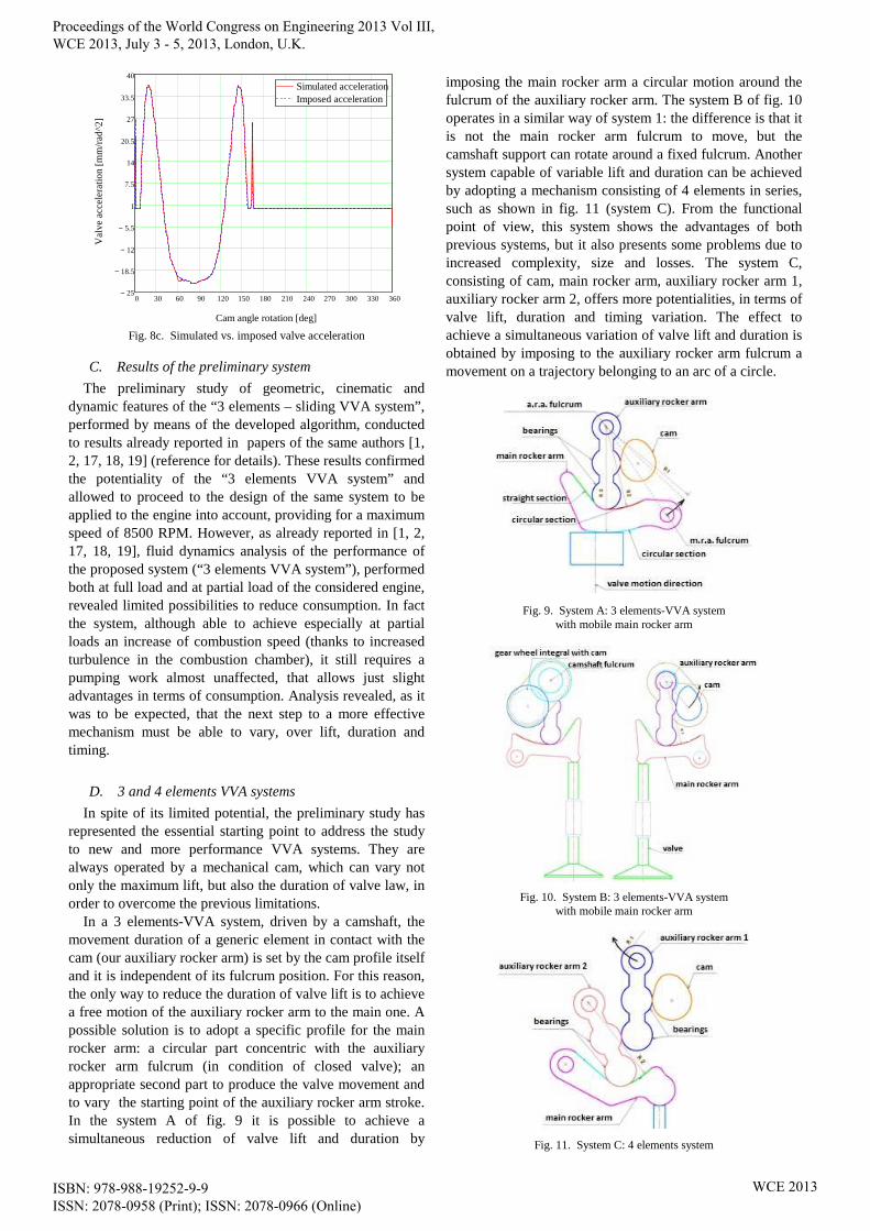
In a 3 elements-VVA system, driven by a camshaft, the movement duration of a generic element in contact with the cam (our auxiliary rocker arm) is set by the cam profile itself and it is independent of its fulcrum position. For this reason, the only way to reduce the duration of valve lift is to achieve a free motion of the auxiliary rocker arm to the main one. A possible solution is to adopt a specific profile for the main rocker arm: a circular part concentric with the auxiliary rocker arm fulcrum (in condition of closed valve); an appropriate second part to produce the valve movement and to vary the starting point of the auxiliary rocker arm stroke. In the system A of fig. 9 it is possible to achieve a simultaneous reduction of valve lift and duration by
imposing the main rocker arm a circular motion around the fulcrum of the auxiliary rocker arm. The system B of fig. 10 operates in a similar way of system 1: the difference is that it is not the main rocker arm fulcrum to move, but the camshaft support can rotate around a fixed fulcrum. Another system capable of variable lift and duration can be achieved by adopting a mechanism consisting of 4 elements in series, such as shown in fig. 11 (system C). From the functional point of view, this system shows the advantages of both previous systems, but it also presents some problems due to increased complexity, size and losses. The system C, consisting of cam, main rocker arm, auxiliary rocker arm 1, auxiliary rocker arm 2, offers more potentialities, in terms of valve lift, duration and timing variation. The effect to achieve a simultaneous variation of valve lift and duration is obtained by imposing to the auxiliary rocker arm fulcrum a movement on a trajectory belonging to an arc of a circle.
Fig. 9. System A: 3 elements-VVA system with mobile main rocker arm
Fig. 10. System B: 3 elements-VVA system with mobile main rocker arm
Fig. 11. System C: 4 elements system
Proceedings of the World Congress on Engineering 2013 Vol III, WCE 2013, July 3 - 5, 2013, London, U.K.
ISBN: 978-988-19252-9-9 ISSN: 2078-0958 (Print); ISSN: 2078-0966 (Online)
WCE 2013
For all systems mentioned above, the first problem is the choice of a junction curve between the circular section and the straight one of the main rocker arm. To ensure continuity and regularity of the function of the angular velocity of the main rocker arm, the connection must necessarily have a radius of curvature greater than the local radius of the auxiliary rocker arm, at every point.
After geometric/mathematical analysis (the discussion is omitted), the result is that to ensure the continuity of angular acceleration law of the main rocker arm (and so the continuity of linear acceleration of the valve), it is necessary that the upper surface of the main rocker arm is made up of a class C2 curve (the curvature changes continuously along the profile). The continuity of the acceleration is necessary to ensure the continuity of inertial forces and consequently of contact forces, and the reduction of vibration phenomena. The easiest way to get a connection with the above properties is to use a cubic spline curve type.
A common problem in the studied three systems is represented by the increase of maximum and minimum accelerations in condition of partial valve lift. A method to control acceleration values is to adopt a cam profile to ensure constant angular velocity to the auxiliary rocker arm along a sufficient portion of contact zone, followed by deceleration to reach the maximum valve lift. In this way, fixed maximum lift law, you can get the required lift law thanks to an appropriate top surface of the main rocker arm and of the cam. In fact, the contact area will always be at constant angular velocity or during deceleration of the auxiliary rocker arm: the maximum acceleration of the valve will be (in the worst hypothesis) equal to the maximum acceleration at maximum lift.
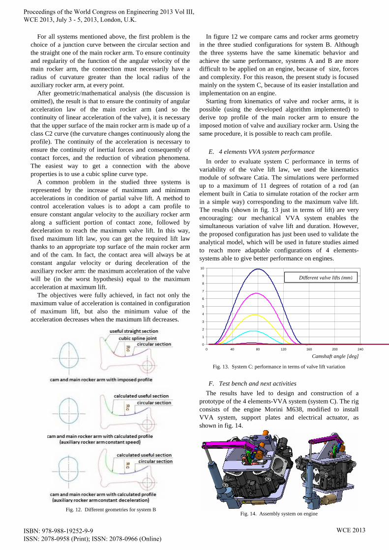
The objectives were fully achieved, in fact not only the maximum value of acceleration is contained in configuration of maximum lift, but also the minimum value of the acceleration decreases when the maximum lift decreases.
Fig. 12. Different geometries for system B
In figure 12 we compare cams and rocker arms geometry in the three studied configurations for system B. Although the three systems have the same kinematic behavior and achieve the same performance, systems A and B are more difficult to be applied on an engine, because of size, forces and complexity. For this reason, the present study is focused mainly on the system C, because of its easier installation and implementation on an engine.
Starting from kinematics of valve and rocker arms, it is possible (using the developed algorithm implemented) to derive top profile of the main rocker arm to ensure the imposed motion of valve and auxiliary rocker arm. Using the same procedure, it is possible to reach cam profile.
E. 4 elements VVA system performance
In order to evaluate system C performance in terms of variability of the valve lift law, we used the kinematics module of software Catia. The simulations were performed up to a maximum of 11 degrees of rotation of a rod (an element built in Catia to simulate rotation of the rocker arm in a simple way) corresponding to the maximum valve lift. The results (shown in fig. 13 just in terms of lift) are very encouraging: our mechanical VVA system enables the simultaneous variation of valve lift and duration. However, the proposed configuration has just been used to validate the analytical model, which will be used in future studies aimed to reach more adaptable configurations of 4 elements-systems able to give better performance on engines.
0
1
2
3
4
5
6
7
8
9
10
0 40 80 120 160 200 240 Camshaft angle [deg]
Fig. 13. System C: performance in terms of valve lift variation
F. Test bench and next activities
The results have led to design and construction of a prototype of the 4 elements-VVA system (system C). The rig consists of the engine Morini M638, modified to install VVA system, support plates and electrical actuator, as shown in fig. 14.
Fig. 14. Assembly system on engine
Different valve lifts (mm)
Proceedings of the World Congress on Engineering 2013 Vol III, WCE 2013, July 3 - 5, 2013, London, U.K.
ISBN: 978-988-19252-9-9 ISSN: 2078-0958 (Print); ISSN: 2078-0966 (Online)
WCE 2013
In order to test the VVA system and evaluate its performance, a test bench has been designed and realized, with oscillating case motor controlled by an inverter.
The test bench will be equipped with: load cell, encoder, position sensor on the actuator piston, high frequency position sensor for valve position, data acquisition system. With the described equipment the aim will be to evaluate the VVA system performance (reliability, torque, average and instantaneous power absorbed by the system, etc.) and to check the correspondence of the obtainable valve laws with the project ones.
III. CONCLUSIONS
After this study, we concluded that the preliminary system presents advantages in terms of design and simplicity of manufacturing, but certainly it presents disadvantages in terms of use at high rotational speed and concerning impossible complete closing valve. DIME research group is performing simulations to verify and optimize VVA system object of study: results represent a basis for development of the project. A disadvantage of this new system is: if this VVA is not used in combination with a VVT, there are no significant advantages in terms of consumption. The advantages refer to an increase of turbulence and a consequent increase of combustion speed.
The future developments are about the opportunity to combine this VVA system with other systems capable to change duration and timing. In this way it would be possible to use different turbulences generated by the different lift laws under the best conditions of timing. This solution would lead to a greater efficiency of the system and to a significant reduction in terms of consumption. Currently we are proceeding to build a prototype to test.
REFERENCES
[1] C. Abagnale, S. Caruso, A. Iorio, M.no Migliaccio, O. Pennacchia, “A new mechanical variable valve actuation system for motorcycle engines”, ICE 2009 – 9th International Conference on Engines & Vehicles, 13 – 17 september 2009 – Capri (NA)
[2] C. Abagnale, PhD thesis (2009) “Sviluppo di un sistema di attuazione variabile VVA elettroidraulico per motori pluricilindrici”, Università degli Studi di Napoli Federico II
[3] Gray C., “A Review of Variable Engine Valve Timing”, SAE paper 880386
[4] Grohn M., Wolf K., “Variable Valve Timing in the new Mercedes–Benz Four-Valve Engines”, SAE 891990.
[5] Lancefield T. M., Gayler R. J., Chattopadhay A., “The Practical Application and Effects of a Variable Event Valve Timing System”, SAE paper 930825, SAE Int. Congr. & Exp., Detroit, MI, USA, marzo 1993.
[6] Lee J.-C., Lee C.W., Nitkiewicz J. A., “The Application of a Lost Motion VVT System to a DOHC SI Engine”, SAE paper 950816, SAE Int. Cong. & Exp., Detroit, MI, USA., 1995.
[7] R.A. Stein, K.M. Galietti, T.G. Leone, “Dual Equal VCT – A Variable Camshaft Timing Strategy for Improved Fuel Economy and Emissions”. SAE paper 950975
[8] T.G. Leone, E.J. Christenson , R.A. Stein, “Comparison of Variable Camshaft Timing Strategies At Part Load”. SAE paper 960584
[9] Moriya Y., Watanabe A., Uda H., Kawamura H., Yoshioka M., Adachi M., “A Newly Developed Intelligent Variable Valve Timing System – Continuously Controlled Cam Phasing as Applied to a New 3 Liter Inline 6 Engine”, SAE paper 960579, SAE Int. Congr. & Exp., Detroit, MI, USA., 1996.
[10] Fukuo K., Iwata T., Sakamoto Y., Imai Y., Nakahara K., Lantz K. A., “Honda 3.0 Liter, New V6 Engine”, SAE paper 970916, SAE Int. Cong. & Exp., Detroit, MI, USA., February 1997.
[11] R. Steinberg, I. Lenz, G. Koehnlein, M.E. Scheidt, T.Saupe, W. Buchinger, “A Fully Continuous Variable Cam Timing Concept for Intake and Exhaust Phasing” Sae paper 980767.
[12] Urata Y., Umiyama H., Shimizu K., Fujiyoshi Y., Sono H., Fukuo K., “A Study of Vehicle Equipped with Non-Throttling S. I. Engine with Early Intake Valve Closing Mechanism”, SAE paper 930820.
[13] 13. Hitomi, M., Sasaki, J., Hatamura, K., and Yano, Y., “Mechanism of Improving Fuel Efficiency by Miller Cycle and Its Future Prospect,” SAE Paper 950974, 1995.
[14] Yaodong Wang, Lin Lin, Shengchuo Zeng, Jincheng Huang, Anthony P. Roskilly, Yunxin He, Xiaodong Huang, Shanping Li, “Application of the Miller cycle to reduce NOx emissions from petrol engines”, Applied Energy 85 (2008) 463–474. ELSEVIER.
[15] Bozza F., Gimelli A., Tuccillo R.. (2002-2003). “The control of a VVA-Equipped SI Engine Operation by Means of 1D Simulation and Mathematical Optimization”. SAE 2002 World Congress & Exhibition. 4-7 March 2002. (vol. SP-1692). SAE paper 2002-01-1107.
[16] Ludwig, B., “Less CO2 Thanks to the BMW 4-Cyl. Valvetronic Engine”, ATA International Conference on Spark Ignition Engine: The CO2 Challenge, Paper 02A5011, Venezia, Italy, November, 2002.
[17] C. Abagnale, M.no Migliaccio, O. Pennacchia, Brevetto italiano n. CE2010A000002 “Sistemi di distribuzione variabile di tipo meccanico a 3 ed a 4 elementi attivi”
[18] C. Abagnale, A. Gimelli, M.no Migliaccio, O. Pennacchia, “Distribuzione variabile su motori alternativi a c.i.: VVA meccanici a 3 e a 4 elementi”, 65° Congresso ATI, Cagliari, settembre 2010
[19] C. Abagnale, M.no Migliaccio, O. Pennacchia, “Design of a new mechanical variable valve actuation system for motorcycle engines”, ESDA2012-82317, Proceedings of the ASME 2012 11th Biennial Conference On Engineering Systems Design And Analysis, July 2-4, 2012, Nantes, France
Proceedings of the World Congress on Engineering 2013 Vol III, WCE 2013, July 3 - 5, 2013, London, U.K.
ISBN: 978-988-19252-9-9 ISSN: 2078-0958 (Print); ISSN: 2078-0966 (Online)
WCE 2013


![Progress in Camless Variable Valve Actuation with Two ... Articles/Progress in camless variable...camless technologies in emission reduction as well as fuel economy [17]. A family](https://img.dokumen.tips/doc/110x75/5aa889937f8b9a6c188bb001/progress-in-camless-variable-valve-actuation-with-two-articlesprogress-in-camless.jpg)