Embed Size (px)
Citation preview
SM
Rugged. Dependable. PIONEER.
MVR SeriesMechanical Truck
Restraints
MVR Series
P.O. Box 338 • Spring Hill, Tennessee 37174 • 1-800-251-3382 • fax: 931-486-0316 • www.pioneerleveler.com

The MVR is designed for grade mounting at dock face. Proper performance relies on adequate preparation
and installation. Read the manual to fully familiarize yourself with the added value of this safety
equipment. When properly installed and operated the MVR will provide many years of optimal service.
Be sure adequate electrical service is offered (MVR-103 and MVR-105) to insure proper operation of
all electrical circuits.
If any information provided herein is not fully understood contact your local PIONEER representative
or PIONEER direct.

“IMPO
RTAN
T”Visually
inspectthe
uniteach
time
itis
used.
Make
specialnoteof
propercaution
lightoperation
andcorrect
hookm
ovement.
Standard
LockO
ut/
TagO
utprocedures
must
beenforced
in
caseof
anyof
thefollow
ing:
•LED
lightfailure
•H
ookdoesn’t
move
becauseofdebris
or
damage.
•Any
typeofelectricalor
mechanicalm
alfunction.
W WA AR R
N NI IN N
G G: :
Premature trailer departure could
result in severe injury of even death.
Always visually inspect the unit to
make sure it is secured to the IC
C bar.

08 / 05 Pioneer Loading Dock Equipment – “MVR” Series Mechanical Truck Restraint Page 1
ARRANGEMENT OF THE DOCK AREA
This unit is designed for gradelevel location. If local conditionswarrant, the Restraint Consolemay be located above grade.PIONEER recommends limitingabove grade mounting to lessthan 2'' to maintain clearance forprojected new standards allowinglower ICC frame sections.
The success and strength of anyinstalled product relies heavily onthe conditions of the materialsurrounding the installation site.This will include the dock face andadjoining drive area for theMVR-100 (MVR-103 & MVR- 105)Vehicle Restraint. Repair anystructural defects to the dock faceand/or drive prior to attemptingequipment installation. Ifnecessary, prepare alternateattachment methods toaccommodate on-site conditionsor contact your local representativeor PIONEER to assist in preparationof accessories needed toadequately secure this product.
POSITION SIGNAL TO CLEAR DOORSEAL. ABOUT 15” TO JAMB ON 8’0”DOOR OPENING CENTER HOUSINGABOUT 90” ABOVE GRADE FORTRACTOR TRAILER SERVICE.
DOCK LEVELER
EXTERIOR TRAFFIC SIGNAL
ELECTRICAL SERVICE 1 20 / 1 /USE 1 / 2 CONDUIT (MIN.)BETWEEN ALL COMPONENTS
INTERIOR LIGHT BOX MOUNT ABOUT60” ABOVE FLOOR TO BOTTOM.
MVR VEHICLE RESTRAINT MOUNT CENTRALTO DOOR OPENING AGAINST DOCK FACE.
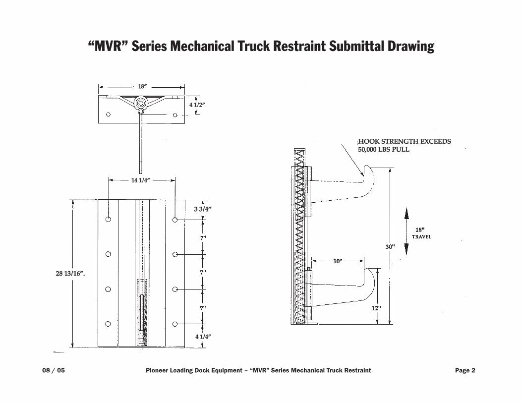
“MVR” Series Mechanical Truck Restraint Submittal Drawing
HHOOOOKK SSTTRREENNGGTTHH EEXXCCEEEEDDSS5500,,000000 LLBBSS PPUULLLL
08 / 05 Pioneer Loading Dock Equipment – “MVR” Series Mechanical Truck Restraint Page 2
33 33//44””
2288 1133//1166””..
1188””
44 11//22””
1144 11//44””
44 11//44””
08/ 05 Pioneer Loading Dock Equipment – “MVR” Series Mechanical Truck Restraint Page 3
ARRANGEMENT OF THE DOCK AREA
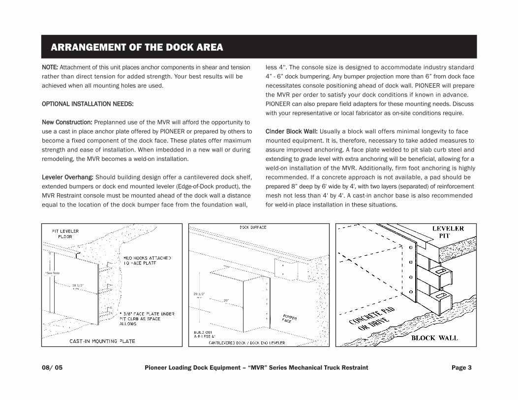
NNOOTTEE:: Attachment of this unit places anchor components in shear and tensionrather than direct tension for added strength. Your best results will beachieved when all mounting holes are used.
OOPPTTIIOONNAALL IINNSSTTAALLLLAATTIIOONN NNEEEEDDSS::
NNeeww CCoonnssttrruuccttiioonn:: Preplanned use of the MVR will afford the opportunity touse a cast in place anchor plate offered by PIONEER or prepared by others tobecome a fixed component of the dock face. These plates offer maximumstrength and ease of installation. When imbedded in a new wall or duringremodeling, the MVR becomes a weld-on installation.
LLeevveelleerr OOvveerrhhaanngg:: Should building design offer a cantilevered dock shelf,extended bumpers or dock end mounted leveler (Edge-of-Dock product), theMVR Restraint console must be mounted ahead of the dock wall a distanceequal to the location of the dock bumper face from the foundation wall,
less 4''. The console size is designed to accommodate industry standard4” - 6” dock bumpering. Any bumper projection more than 6” from dock facenecessitates console positioning ahead of dock wall. PIONEER will preparethe MVR per order to satisfy your dock conditions if known in advance.PIONEER can also prepare field adapters for these mounting needs. Discusswith your representative or local fabricator as on-site conditions require.
CCiinnddeerr BBlloocckk WWaallll:: Usually a block wall offers minimal longevity to facemounted equipment. It is, therefore, necessary to take added measures toassure improved anchoring. A face plate welded to pit slab curb steel andextending to grade level with extra anchoring will be beneficial, allowing for aweld-on installation of the MVR. Additionally, firm foot anchoring is highlyrecommended. If a concrete approach is not available, a pad should beprepared 8” deep by 6' wide by 4', with two layers (separated) of reinforcementmesh not less than 4' by 4'. A cast-in anchor base is also recommendedfor weld-in place installation in these situations.
29 1/2”
20”
18 1/2”
*See Note
Read and understand all instructions prior to installation or operation of thissafety equipment.
The MVR is shipped completely assembled and factory tested. This productdisplayed proper operation under factory conditions prior to shipment and isready to install. Inspect all materials received and review arrangement layoutincluded to preview installation setup needs.
Review the dock face area directly beneath the location where truck dockingoccurs. Remove or relocate any obstacles which would prevent flush andsecure mounting of this product. Repair any weakness observed in themounting area. If conditions warrant, prepare a slab for base mounting ofthe MVR.
NNOOTTEE:: Base mounting in conjunction with wall mounting provides theultimate opportunity to maximize the installed strength of this safetyequipment and is highly recommended particularly when wall conditions maynot be optimum. However, local conditions including floating yard slabs orpoor drive construction may negate or minimize the value of this feature.Particular attention should be given other opportunities to offer a maximuminstalled strength of this product in the event a portion of the prescribedinstallation method requires deviation from that noted. (See list of optionalmounting alternatives.)
Position Restraint console and mark dock face and grade for anchors. Unitshould be positioned to sit plumb (vertical) and level (horizontal) and asfirmly against dock face as possible. Shim beneath bottom mounting railsas needed to provide firm footing. Shims should be steel and welded intoposition to avoid creepage or accidental dislocation. This unit is prepared for5/8” diameter anchors. Minimum length recommended is 5” for wedge typeanchors. (See other instructions if dock is not poured concrete construction).Eight (8) hole locations are provided for wall attachment and should all beprepared for anchors.
08 / 05 Pioneer Loading Dock Equipment – “MVR” Series Mechanical Truck Restraint Page 4
SECTION 1 INSTALLATION PROCEDURE
Grade attachment should be offered as allowed by conditions. Use sametechnique as wall mount if yard has concrete pad or drive. Compensatelength of anchor for any shim addition under mounting plate. For black topor hard compacted drives provide anchor rods of 1/2” diameter by about 15”long.* These should be prepared with a modestly pointed nose to be driveninto the ground surface through the mounting holes offered. The top endshould then be welded to secure rod to Restraint base.
The operating range of the MVR offers engagement of most legally mountedICC frame members. The unit performance will be limited to the position andstrength of the ICC frame section which varies by manufacturer and designas well as its condition due to the extent of its maintenance, age and possibleabuse. The MVR will accept very high stress and pulling forces, however, thistoo can be limited by installation technique, anchors and materials and / orthe condition of the dock wall and drive area. Conditions or equipmentfailure due to accident or inadequate preparations and / or reasonablemaintenance of the dock area and its equipment could result in furtherproperty damage or personal injury.
*Use 1/2” diameter rebar or similar for good grip characteristics.
NNOOTTEE:: WWhheerree ppoossssiibbllee,, wweelldd tthhee bbaacckk ooff tthhee rreessttrraaiinntt ttoo tthhee eemmbbeeddddeeddccuurrbb aannggllee aatt tthhee ffrroonntt // lleeaaddiinngg eeddggee ooff tthhee ppiitt lleevveelleerr..
08 / 05 Pioneer Loading Dock Equipment – “MVR” Series Mechanical Truck Restraint Page 5
MOUNTING INSIDE AND OUTSIDE LIGHTS
Mount Inside Light Package (MVR 103 & MVR 105) to convenient locationwhich provides a good view for dock attendant of loading area. We recommendleft side of opening looking “out” as shown in dock arrangements diagramas this simplifies installation. Right side of doorway mounting is fine ifinstallation conditions warrant.
Mount exterior traffic light on truck driver’s side of exterior wall (left sidefacing out) in area clearly visible to driver. Be certain to offer clearance forfuture or current installations of seal/shelter products. Light housing shouldbe 8-9’ above grade as noted on arrangement diagram.
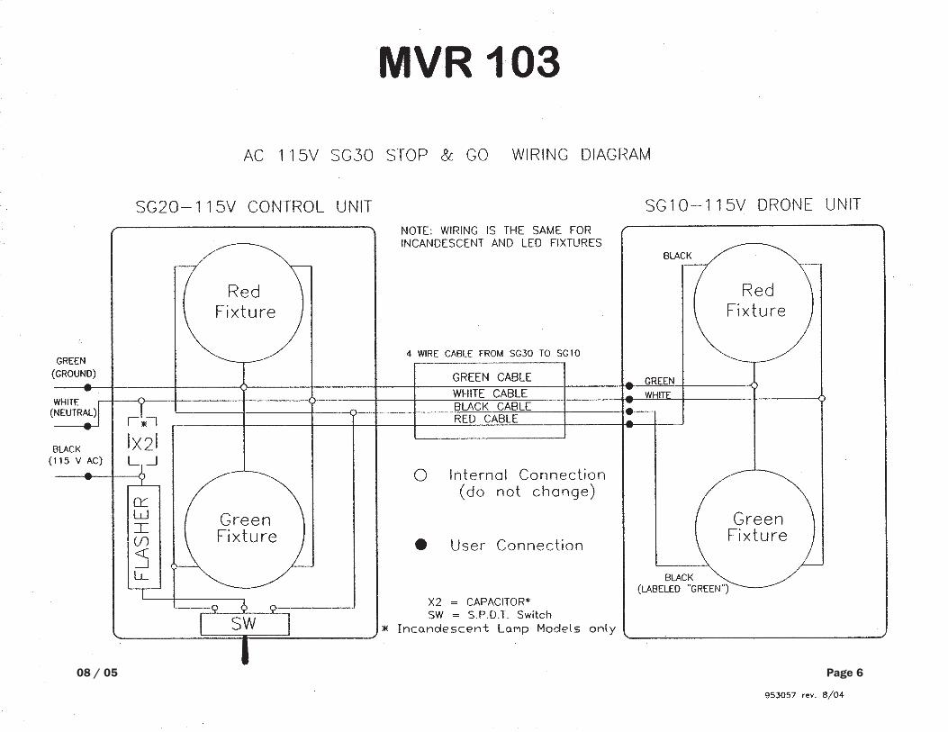
Route conduit (MVR 103 & MVR 105) and connectors (supplied by electricalinstaller) to join inside and outside light box (wire also to be supplied byinstaller). Make connections per diagram provided in light package.
Install trucker’s instruction signs above and below traffic light whereclearly visible to incoming traffic.
Supply and connect incoming electrical power light boxes per encloseddiagram.
SECTION 2 INSTALLATION INSTRUCTIONS
08 / 05 Page 6

08 / 05 Page 7

Flasherlocated
ininterior
lightpanel
PIO
NE
ER
LO
AD
ING
DO
CK
EQ
UIP
ME
NT
MV
R105
EL
EC
TR
IC SC
HE
MA
TIC
WIT
H F
LA
SHE
R
08 / 05 Page 8
Properly installed and serviced this Vehicle Restraint will greatly enhancesafety during truck loading/unloading operations and should offer manyyears of service without a regular maintenance schedule. This product isdesigned for use in the outdoor environment. Regional and seasonal climatevariables offer a wide range of maintenance possibilities for equipmentexposed to the elements. The factory adjustment of this product offeredproper operation prior to shipment. Although the factory attempts to offerequipment which will display normal operation for most installations, localconditions may require attention at installation to cope with specific site needs.
Please contact the factory to review any installation or equipment issue whichis not covered by this manual or which is not fully understood.
Contact your authorized PIONEER representative for required service oradjustments.
08 / 05 Pioneer Loading Dock Equipment – “MVR” Series Mechanical Truck Restraint Page 9
SECTION 3 ADJUSTMENTS

08 / 05 Pioneer Loading Dock Equipment – “MVR” Series Mechanical Truck Restraint Page 10
SECTION 4 OPERATION
The PIONEER MVR Vehicle Restraint uses a simple extension spring toengage and disengage the locking hook of this unit. This system eliminatesthe need for regular maintenance although an adjustment as previouslynoted may be in order. The Restraint hook is activated and retracted asfollows:
With the truck docked firmly against the bumper face, the dock attendantsimply engages the activation rod to push down and turn the hook so that itcan rise and engage the ICC bar. He then flips the switch (MVR 103) on theinside light box and the exterior traffic signal will switch from green to red(the MVR 105 lights will change automatically via a limit switch) to advise thetrucker not to attempt a departure. The inside light will switch to green toadvise a good loading condition. A brief check of the engagement shouldshow the ICC frame entrapped by the restraining hook of the MVR. If thetruck is noted to have a weak or missing ICC frame the attendant should
RReessttrraaiinntt CCoonnssoollee:: A heavy steel housing, to enclose the operatingcomponents of the MVR, serves as the mounting framework for the unitinstallation. The console is offered for grade level mounting against thedock wall face. Alternate mounting options are available to satisfy uniquelocal conditions.
RReessttrraaiinntt HHooookk:: Operates to engage the ICC frame section of the truck ortrailer chassis. When engaged the Restraint hook offers resistance to truckmovement. When disengaged the Restraint hook is stored flat against thehousing to allow free passage of docking or departing vehicles.
advise supervision of the noted problem and see that other measures aretaken to secure the truck prior to loading or unloading. The MVR shouldremain engaged to offer a secondary opportunity by controlling truck trafficwith its exterior traffic light.
When the truck is ready to depart, the dock attendant engages the activationrod, pushes down on the hook and turns it to the left to secure it. He thenflips the manual switch (MVR 103) on the inside light box and the exteriortraffic light will switch from red to green to release the docked truck;(the MVR 105 lights will change automatically via a limit switch) and theinterior visual display will switch to red to advise caution around the dock areabecause the MVR is now deactivated and the truck may leave at any time.
EExxtteennssiioonn SSpprriinngg:: The MVR is activated by an extension spring and stored tothe side by pushing down, turning to the left and releasing hook to engagestorage hook.
AAccttiivvaattiioonn BBaarr:: Bar is stored away from unit and is uniquely constructedto act as neutral counter balance to activation spring.
IInntteerriioorr//EExxtteerriioorr TTrraaffffiicc LLiigghhttss:: High impact polymer enclosures for housingred and green visual traffic control indicators to display docking or no-goconditions for trucker. To open light housing, screw clamps must beloosened to service lights or wiring.
SECTION 5 MAJOR COMPONENTS

08 / 05 Pioneer Loading Dock Equipment – “MVR” Series Mechanical Truck Restraint Page 11
SECTION 6 SPECIFICATIONS
EElleeccttrriiccaall:: 120V AC, 20A.
WWiirriinngg:: Refer to field arrangement drawing (Page 1) for conduit and wireneeds. Wiring diagram included in light box.
LLiimmiitt SSwwiittcchheess:: Industrial quality momentary contact type. Used to controltraffic signals and stop cycle in motor control circuit. (MVR 105)
MMaaiinntteennaannccee PPrroocceedduurree:: Shut off electrical power before lamp replacement.
QQuuiicckk CChheecckk:: Are all lamps on when required in cycle?
VViissuuaall IInnddiiccaattoorr:: Proper traffic signals are critical to this safety equipment.Review functions on Page 7. Verify correct lamps on / off during lock / unlockcycles. See specifications on this page for replacement bulbs. Shut poweroff before lamp replacement.
IInntteerriioorr//EExxtteerriioorr LLiigghhttss:: (Red and Green) Sealed beam lamps, 120V.
RReedd LLEEDD lleennss:: Part No. 9489
GGrreeeenn LLEEDD lleennss:: Part No. 9488
SECTION 7 MAINTENANCE
LLuubbrriiccaattiioonn:: This product is designed to function without excessive lubrication.However, a squirt of white lithium grease or similar product on hook slide willhelp promote a smooth operation.

WARRANTY
PIONEER MANUFACTURING, INC. guarantees its MVR Series Truck Restraint to be free from defectsin materials and workmanship for a period of one (1) full year from date of shipment.
A claim for breach of warranty will be honored if the product has been properly installed, maintainedand operated and not damaged by abuse.
PIONEER will exchange or repair any structural component found to be defective in nature.
PIONEER MANUFACTURING, INC. SHALL NOT BE LIABLE FOR LOSS OF USE OF ANY EQUIPMENTOR INCIDENTAL DAMAGES.

CAUTION:
Contact your PIONEER representative or the factory if a malfunction occurs which is not understood.DO NOT attempt to correct the situation without proper information and understanding, as this maydamage components and void the warranty.
SERVICE AND MAINTENANCE
PIONEER recommends periodic inspection and servicing of the MVR Truck Restraint to assureproper operation and maximum life span of the unit. Units should be inspected a minimum ofevery six months, and if needed, can be adjusted and lubricated. Contact your local PIONEERdealer to secure a complete maintenance plan.