Embed Size (px)
Citation preview

The Mechanical Tester has been designed with leading edge technologies in order to give the highest accuracy and repeatability on the widest
range of measurements. This focus on quality ensures durability with the lowest cost of ownership in the industry. The Nano and Micro Modules
perform all modes of testing including indentation, scratch and wear; no interchange of modules needed and with true feedback load control
from independent load and depth sensors. With indentation testing, users obtain depth versus load curves giving hardness, elastic modulus, yield
strength, loss and storage modulus and many others. While with scratch testing, users can quantify the scratch and marring resistance of coatings
and substrates in addition to measuring plastic and elastic deformations. With wear testing at constant load, users can precisely measure
coefficient of friction and wear properties. The powerful software offers a unique combination of features for each test modes. A complete
system, the Mechanical Tester is the ideal solution for determining the full range of mechanical properties of thin or thick, soft or hard coatings,
films and substrates. Many advanced software features including Fast Map, Tracking zoomed View, Navigation Plus, Broadview Map Selection and
Single Indent Area Function (EP No. 3076153) makes the Mechanical Tester the most automated and user-friendly system on the market.
MECHANICAL TESTERS

38 x 33 x 70 cm
Color video zoom option
Automated 50mmx100mm X-Y control
Compact base
Nano or Micro Module
Automated
50mm Z control
Standard or custom sample stage and
temperature and humidity control options
Spacious and open platform
CB500The CB500 allows a single module, either the nano or micro, each with the full range of testing modes including hardness, scratch and wear. Nowhere else can you find this wide use with a single module and at competitive compact price. It is equipped with automated 50mm x 100mm X-Y stages, a 50mm Z stage and a video zoom microscope. A CB500 version with manual X-Y table offers full indentation capabilities at the most affordable price. All CB500 bases can also accommodate the heating oven and the cooling/humidity control chamber for environmental control testing. It is the ideal solution for quality control and research applications with focus in one broad load range. Compact & modern design, broad application use, robust with low cost of ownership and a highly competitive price.
BASE
Maximum # of Modules
X&Y Motorized Stages
XY Lateral Accuracy
Z Motorized Approach (range)
Base Type
Desktop Dimensions
Stand-Alone Dimensions
Zoom Video Microscope
3D Optical Profiler
AFM
High Speed Fretting Wear
CB500
1 (Nano or Micro)
100 x 50mm
1μm
50mm
Desktop
38 x 33 x 70cm
N/A
1600 x 1200 Camera
N/A
N/A
N/A
3 MODES NANO OR MICRO
Indentation
Scratch
Wear
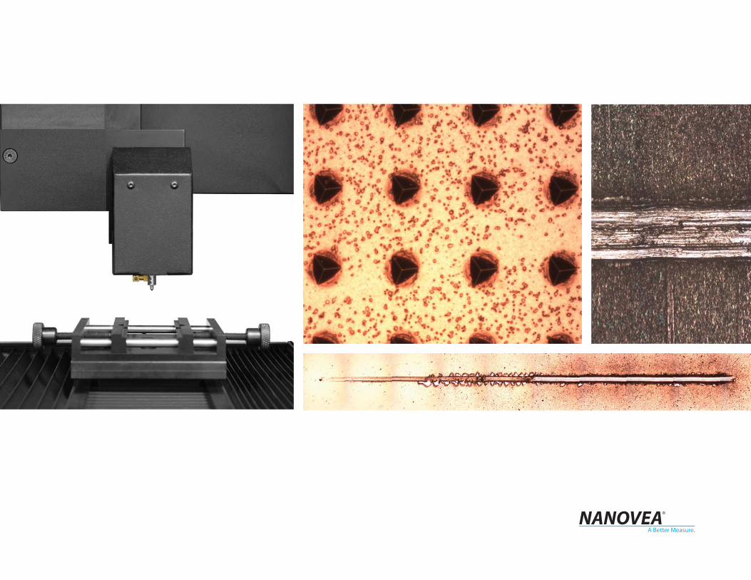
Nano & Micro
on a single system
Color video camera
AFM or optical
profiler integration
Adjustable height clearance
Spacious and open platform
Joypad stage control
Standard or custom sample
stage and temperature and
humidity control options
Microscope video zoom
imaging with options
62 x 62 x 82 cm
Automated 200 x150mm
XY control
Automated 50mm Z control
PB1000The PB1000 allows up to two modules on a single system providing the widest load and most accurate testing capabilities available. Equipped with automated 200mm x 150mm XY motorized tables and a 50mm Z motorized table. A gas-spring slide allows adjusting of the height clearance to up to a total of 140mm for varying sample sizes. This base can also accommodate the heating oven and the cooling/humidity chamber for environmental control testing. In addition to the full video zoom, an AFM and an Optical Profiler are optional. The Platform is the ideal option for diverse and expanding measurement needs. Nano to micro range with no need to exchange, spacious platform with adjustable height clearance, fully upgradeable, robust and low cost of ownership.
BASE
Maximum # of Modules
X&Y Motorized Stages
XY Lateral Accuracy
Z Motorized Approach (range)
Base Type
Desktop Dimensions
Stand-Alone Dimensions
Zoom Video Microscope
3D Optical Profiler
AFM
High Speed Fretting Wear
PB1000
2 (Nano & Micro)
200 x150mm
0.25μm
50mm (+ 140mm manual extra slide)
Desktop or Stand-Alone
62 x 62 x 82cm
92 x 92 x 183cm
1600x1200 Camera
Optional
Optional
Custom up to 40 Hz
6 MODES NANO & MICRO
Indentation
Scratch
Wear
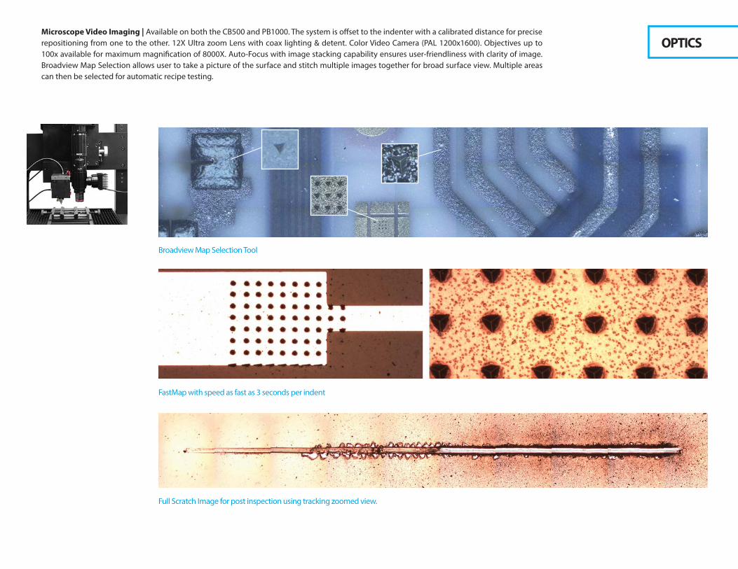
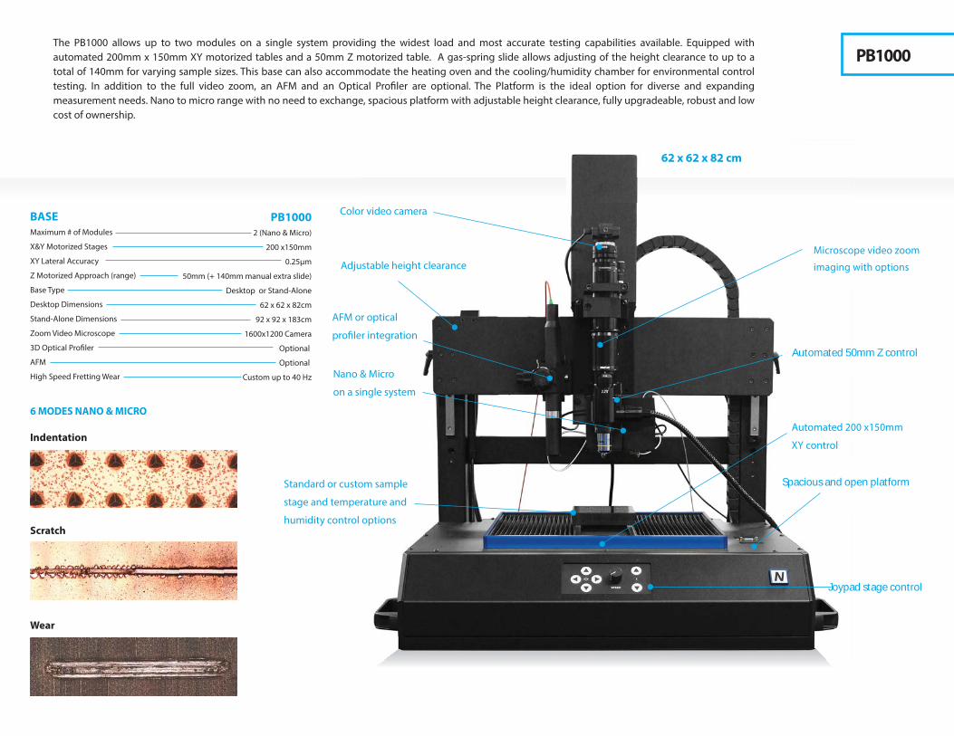
Microscope Video Imaging | Available on both the CB500 and PB1000. The system is offset to the indenter with a calibrated distance for precise repositioning from one to the other. 12X Ultra zoom Lens with coax lighting & detent. Color Video Camera (PAL 1200x1600). Objectives up to 100x available for maximum magnification of 8000X. Auto-Focus with image stacking capability ensures user-friendliness with clarity of image. Broadview Map Selection allows user to take a picture of the surface and stitch multiple images together for broad surface view. Multiple areas can then be selected for automatic recipe testing.
OPTICS
Broadview Map Selection Tool
FastMap with speed as fast as 3 seconds per indent
Full Scratch Image for post inspection using tracking zoomed view.

Designed with the vision of providing clients high accuracy with ease of use, longevity with low maintenance cost; the nano module achieves this with its unique combination of piezo actuator, ultra sensitive load cell and a large surface capacitor ring, all vertically aligned for maximum stiffness. The unique use of independent depth and load sensors ensure high accuracy in all conditions but also provide excellent point of contact detection as the load applied is measured directly by the independent sensor when the indenter first touches the surface. The module also provides true closed control feedback loop using data from independent depth or load sensor. This feature is essential to react quickly and accurately to fast events such as during scratch and wear testing or when fractures occur during indentation. The measurement of the actual load applied ensures also accuracy during fast DMA testing and allows automatic. The ultra sensitive load cell is also straightforward to calibrate with a direct weight scale. Therefore, every Nano module can be quickly calibrated, by the user, in less than 15minutes for Load, Depth and Compliance. This ensures constant accuracy of the data through time and from one instrument to another. Nanovea achieves this high accuracy with some of the best comparative noise levels in the industry.
The module provides nanometer scale testing during indentation, scratch and wear testing modes. Each mode of testing provides wide range of testing that can provide properties such as hardness, creep, elastic modulus, stress-strain curves, yield strength, fatigue, loss and storage modulus, fracture toughness, wear rate, friction coefficient, scratch and marring resistance, plastic/elastic deformation among other tests. In combination with integrated x-y motorized table, one can test at very specific locations or do a full mapping of properties across a chosen area. In fact, the unique design of the nano module with the piezo actuator allows accurate indents to be performed in less than 3 seconds making mapping possible within minutes. The Nano module is ideal for accurately characterizing thin industrial coatings or films. Examples include thin polymer coatings for the medical device industry and various thin coatings for the solar and optical lens industries. Another major application of the nano module is the marring of top surfaces such as varnish clear coats used in the automobile industry and other protective coatings used on portable devices such as mobile electronics.
The Nano Module has been designed for high thermal stability with raw data uncorrected thermal drift of < 0.02 nm/sec. At high temperature, the oven provides uniform temperature of the tip and the sample for increased accuracy and lower levels of drift with no compensation. When used with the high temperature oven, the Nano module is designed with MACOR with low thermal expansion coefficient material of < 10-6 / °C . This reduces any thermal drift at high temperature.
NANO MODULE
Nanoindentation Scratch Adhesion Wear Friction

During Nanoindentation, an indenter tip is driven into the sample by applying an increasing load up to a targeted value. The measured load is then gradually decreased until partial, or complete, relaxation of the sample has occurred. The load and depth from independent sensors are recorded continuously throughout this process to produce a load-displacement curve. Adding a pause at maximum load allows studying of creep properties. DMA (Dynamic Mechanical Analysis) and Continuous Stiffness Measurement (CSM) Oscillation mode allows the measurements of visco-elastic properties, stress-strain curves and all properties versus depth.
Standards:
• ASTM E384 • ASTM G171 • ASTM E2546 • ASTM B933 • ASTM D4065 • ISO 14577 • DIN 50359
Properties Analyzed During Nanoindentation:
• Hardness • Elastic modulus • Hardness & Elastic Modulus vs Temperature or Humidity • Creep & Stress Relaxation with constant load and depth control • Stress-Strain Curve from Continuous Stiffness (CSM) and Multi-Load Cycles • Recovery Depth • Restoration Ratio • Loss and Storage Modulus • Fracture Toughness • Yield Strength • Compression • Fatigue • Puncture Resistance • Adhesion Stickiness • Frequency & Temperature Sweep DMA • Martens Hardness vs Depth • Plastic & Elastic Deformations • Visual Vickers Hardness and many others possible
Nanoindentation Software Features:
• Recipes • Export Raw Data and Images • Real Time Display • Automatic Reporting • Multi-Language Support • Compare Curves and Results on Same or Multi Samples• DMA and Continuous Stiffness • True Depth and Load Feedback Control Loading
Advanced Nanoindentation Automation:
• FastMap: Mapping of Hardness & Elastic Modulus (3 sec per indent) • Broadview Map Selection Tool: Advanced Mapping on stitched image • Automated multi-sample testing (handles height variance of up to 50mm) • Navigation Plus: User Friendly surface navigation imaging• Quick Approach, Auto Surface Detection and Auto Analysis • Direct Easy Calibration Tools for Load & Depth • Single Indent Area Function (European Patent No. 3076153) • Quantifiable quality check for indenter (European Patent No. 3076153) • Wizard (Patent Pending): Automatic Test Parameter generator • Savable recipes of all macros programmed
Indenters: (Diamond, WC and many other materials)• Berkovich • Vickers • Cube Corner • Conical-Spherical • Knoop • Knife • 1 to 6mm balls
Environmental Conditions & Sample(s) Holders:
• 275°C & 450 °C Oven • Down to -10°C Cooling Chamber • Humidity Chamber • Liquid Cups • Custom 3 Point Bending or Puncture • Custom Sample & Indenter Holders
Powerful DMA analysis at constant loading with frequency and temperature sweep
Low load depth versus load indentation 1mN with capability to go down to 40microN
Unique 1 or 3mm ball holder for test on soft gels down to the single kPa
NANOINDENTATION

During Nano Scratch Testing, a conical spherical tip, diamond or WC, is drawn across the coated surface with an increasing load, resulting in various types of failure at specific critical loads. Nano Scratch Adhesion Testing identifies critical loads optically using a built-in video zoom microscope. These critical loads are used to quantify the adhesive and cohesive properties of different film/substrate combinations. In addition, failure points can be determined using frictional force and depth measurements. True Depth Measurements based on (European Patent No. 0663068) providing accurate elastic and plastic deformation.
Standards:
• ASTM D7187 • ASTM C1624 • ASTM D7027 • ASTM G171 • ISO 20502 • ISO 1518 • DIN EN 1071
Properties Analyzed During Nano Scratch:
• Cohesive & Adhesive failure • Adhesion Strength • Marring (Resistance) and Crack/Fracture initiation • Plastic & Elastic Deformation depth and others
Software Features:
• Recipes • Export Raw Data and Images • Real Time Display • Automatic Reporting • Multi-Language Support • Failure Comparison • Mapping • Full Scratch Image for post inspection using tracking zoomed view • Tracking Zoomed View for easy post inspection with data depth, friction analysis
Advanced Nano Scratch Automation:
• Broadview Map Selection Tool: Advanced Mapping on stitched image• Automated multi-sample testing (handles height variance of up to 50mm)• Navigation Plus: User Friendly surface navigation imaging• Quick Approach, Auto Surface Detection and Auto Analysis• Direct Easy Calibration Tools for Load & Depth• Single Indent Area Function (European Patent No. 3076153)• Quantifiable quality check for indenter (European Patent No. 3076153)• Wizard (Patent Pending): Automatic Test Parameter generator • Savable recipes of all macros programmed
Indenters: (Diamond, WC and many other materials)• Vickers • Cube Corner • Conical-Spherical • Knife
Environmental Conditions & Sample(s) Holders:
• 275°C & 450 °C Oven • Down to -10°C Cooling Chamber • Humidity Chamber • Liquid Cups • Custom Sample & Indenter Holders
Highly accurate friction force & coefficient measurements
Highly accurate surface profile, scratch depth & residual depth measurements
Full scratch imaging for failure identification & analysis
force & coefficient measurements
e profile, scratch depth & residual depth measurements
NANO SCRATCH

During Nano Wear a pin or a ball is loaded onto a test sample with a stable weight with feedback control. Depth change is recorded precisely during the test using a precision capacitor. Wear rate is calculated with this information. Wear rates for the pin and the sample can also be calculated from the volume of material loss with an attached AFM or Optical Profilometer. Linear mode with friction measurement is possible with the standard x-y motorized table. The nano module can also be used to measure friction coefficient at very low loads.
Standards:
• ASTM G133
Properties Analyzed During Nano Wear:
• Wear Rates • Fretting Wear • Friction Coefficient
Software Features:
• Recipes • Export Raw Data and Images • Real Time Display • Automatic Reporting • Multi-Language Support • Fixed cycle view for friction/depth data at a specific chosen position versus cycle count
Advanced Nano Wear Automation:
• Broadview Map Selection Tool: Advanced Mapping on stitched image • Automated multi-sample testing (handles height variance of up to 50mm) • Navigation Plus: User Friendly surface navigation imaging• Quick Approach, Auto Surface Detection and Auto Analysis • Direct Easy Calibration Tools for Load & Depth • Savable recipes of all macros programmed
Indenters: (Diamond, WC and many other materials)• Conical-Spherical • Vickers • Knife • 1 to 6mm balls
Environmental Conditions & Sample(s) Holders:
• 275°C & 450 °C Oven • Down to -10°C Cooling Chamber • Humidity Chamber • Liquid Cups • Custom Sample & Indenter Holders
Depth at various cycles during wear test
Highly accurate low load capacitive wear depth measurement
Submerged nano friction test
NANO WEAR

Now the world’s leading micro mechanical testing. Automatic, accurate and fast hardness and elastic modulus results obtained from depth versus load data are truly a giant leap compared to traditional hardness testers. This past century technology was based on visual inspection when accurate depth sensors were not available. Therefore, today there is absolutely no advantage with using outdated traditional hardness testers. The Micro Module is faster, easier, more accurate particularly at low loads, and more repeatable. Testing can be performed on any material including very elastic material or on surfaces where identifying the indent is challenging. Not only providing hardness and elastic modulus but also a wide range of testing such as creep, stress-strain curves, yield strength, fatigue, fracture toughness, scratch and marring resistance, plastic/elastic deformation, wear rate and friction coefficient.
And for those using antiquated scratch testing instruments. These systems have a limited range of load and use cantilever load cells prone to side bending that can be seen in observing wavy scratches at high loads. Unlike the micro module that has been designed with a rigid compressive load cell and measures depth using a capacitor directly connected to the shaft holding the indenter. The result is the highest accuracy available on the market. The wide usable range of loads (5 orders of magnitude) of a single micro module makes it possible to do a high load scratch test, at up to 200N for a 5micron and up on a DLC, TiN, TiC coating, and then use a 50mN load to measure hardness and elastic modulus without the influence of the substrate. For thinner coatings down to sub microns, the 20N can be used in the same way with depth versus load down to the single digit mN but still do excellent scratch testing up to 20N. These more sensitive loads are ideal for the characterization of industrial coatings; ranging from plasma processed layers used in semiconductor and optical technology, to decorative and protective coatings used for automobile parts and consumer goods. Easy and fast to calibrate, the accuracy of the data through time and from one instrument to another is insured. High performance longevity with low maintenance cost and especially high accuracy comes standard.
MICRO MODULE
Microindentation Scratch Adhesion Wear Friction

During the Microindentation process an indenter tip is driven into the sample by applying an increasing load up to a targeted value. The measured load is then gradually decreased until partial, or complete, relaxation of the sample has occurred. The load and displacement are recorded continuously throughout this process to produce a load-displacement curve. Adding a pause at maximum load allows studying of creep properties. Other loading modes are possible including constant load multi-cycle for measuring fatigue or plastic-elastic deformation; and increasing load multi-cycle for obtaining properties versus depth.
Standards:
• ASTM E384 • ASTM G171 • ASTM E2546 • ASTM B933 • ISO 14577 • DIN 50359 • DIN 53505• ASTM D2240 • ISO 7619 • JISK7215
Properties Analyzed During Microindentation:
• Hardness • Elastic Modulus • Creep • Stress-Strain Curve • Fracture Toughness • Yield Strength • Compression • Fatigue • Puncture Resistance • Martens Hardness vs Depth • Plastic & Elastic Deformations • Visual Hardness, Shore Hardness and many others possible.
Software Features:
• Recipes • Export Raw Data and Images • Real Time Display • Automatic Reporting • Multi-Language Support • Compare Curves and Results on Same or Multi Samples
Advanced Microindentation Automation:
• FastMap: Mapping of Hardness & Elastic Modulus (3 sec per indent) • Broadview Map Selection Tool: Advanced Mapping on stitched image • Automated multi-sample testing (handles height variance of up to 50mm) • Navigation Plus: User Friendly surface navigation imaging• Quick Approach, Auto Surface Detection and Auto Analysis • Direct Easy Calibration Tools for Load & Depth • Single Indent Area Function (European Patent No. 3076153) • Quantifiable quality check for indenter (European Patent No. 3076153) • Wizard (Patent Pending): Automatic Test Parameter generator• Savable recipes of all macros programmed
Indenters: (Diamond, WC and many other materials)• Berkovich • Vickers • Cube Corner • Conical-Spherical • Knoop • Knife • 1 to 6mm balls• Shore Hardness Tips
Environmental Conditions & Sample(s) Holders:
• 275°C & 450 °C Oven • Down to -10°C Cooling Chamber • Humidity Chamber • Liquid Cups • Custom 3 Point Bending or Puncture • Custom Sample & Indenter Holders
The widest & most accurate range of Microindentation available
Unique Yield Strength technique using a flat diamond indenter
Multi cycle fatigue and failure
MICROINDENTATION
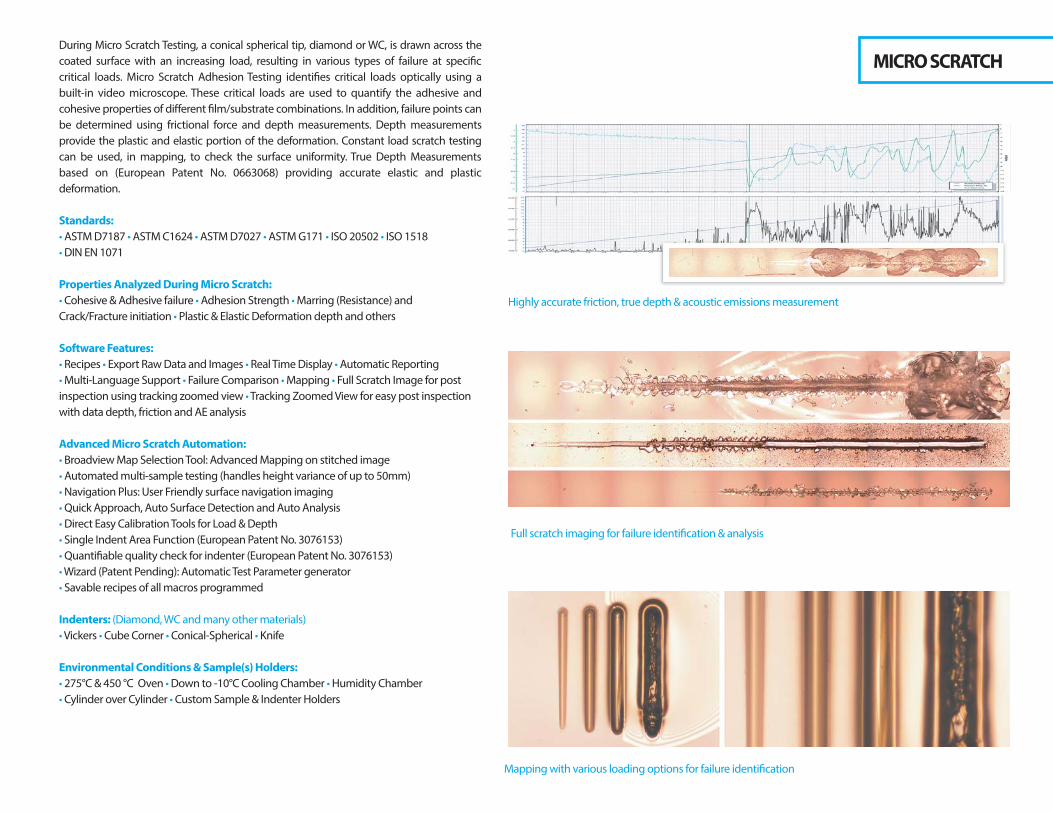
During Micro Scratch Testing, a conical spherical tip, diamond or WC, is drawn across the coated surface with an increasing load, resulting in various types of failure at specific critical loads. Micro Scratch Adhesion Testing identifies critical loads optically using a built-in video microscope. These critical loads are used to quantify the adhesive and cohesive properties of different film/substrate combinations. In addition, failure points can be determined using frictional force and depth measurements. Depth measurements provide the plastic and elastic portion of the deformation. Constant load scratch testing can be used, in mapping, to check the surface uniformity. True Depth Measurements based on (European Patent No. 0663068) providing accurate elastic and plastic deformation.
Standards:
• ASTM D7187 • ASTM C1624 • ASTM D7027 • ASTM G171 • ISO 20502 • ISO 1518 • DIN EN 1071
Properties Analyzed During Micro Scratch:
• Cohesive & Adhesive failure • Adhesion Strength • Marring (Resistance) and Crack/Fracture initiation • Plastic & Elastic Deformation depth and others
Software Features:
• Recipes • Export Raw Data and Images • Real Time Display • Automatic Reporting • Multi-Language Support • Failure Comparison • Mapping • Full Scratch Image for post inspection using tracking zoomed view • Tracking Zoomed View for easy post inspection with data depth, friction and AE analysis
Advanced Micro Scratch Automation:
• Broadview Map Selection Tool: Advanced Mapping on stitched image• Automated multi-sample testing (handles height variance of up to 50mm)• Navigation Plus: User Friendly surface navigation imaging• Quick Approach, Auto Surface Detection and Auto Analysis• Direct Easy Calibration Tools for Load & Depth• Single Indent Area Function (European Patent No. 3076153)• Quantifiable quality check for indenter (European Patent No. 3076153)• Wizard (Patent Pending): Automatic Test Parameter generator• Savable recipes of all macros programmed
Indenters: (Diamond, WC and many other materials)• Vickers • Cube Corner • Conical-Spherical • Knife
Environmental Conditions & Sample(s) Holders:
• 275°C & 450 °C Oven • Down to -10°C Cooling Chamber • Humidity Chamber • Cylinder over Cylinder • Custom Sample & Indenter Holders
Highly accurate friction, true depth & acoustic emissions measurement
Full scratch imaging for failure identification & analysis
Mapping with various loading options for failure identification
on, true depth & acoustic emissions measurement
MICRO SCRATCH

During Micro Wear Testing a pin or a ball is loaded onto a test sample with a stable weight with feedback control. Depth change is recorded precisely during the test using a precision capacitor. Wear rate is calculated with this information. Wear rates for the pin and the sample can also be calculated from the volume of material measured with an attached AFM or Optical Profilometer. Linear mode with friction measurement is possible with the standard x-y motorized table. The micro module can also be used to measure friction coefficient at very high loads.
Standards:
• ASTM G133
Properties Analyzed During Micro Wear:
• Wear Rates • Fretting Wear • Friction Coefficient
Software Features:
• Recipes • Export Raw Data and Images • Real Time Display • Automatic Reporting • Multi-Language Support • Fixed cycle view for friction/depth data at a specific chosen position versus cycle count
Advanced Micro Wear Automation:
• Broadview Map Selection Tool: Advanced Mapping on stitched image • Automated multi-sample testing (handles height variance of up to 50mm) • Navigation Plus: User Friendly surface navigation imaging• Quick Approach, Auto Surface Detection and Auto Analysis • Direct Easy Calibration Tools for Load & Depth • Savable recipes of all macros programmed
Indenters: (Diamond, WC and many other materials)• Conical-Spherical • Vickers • Knife • 1 to 6mm balls
Environmental Conditions & Sample(s) Holders:
• 275°C & 450 °C Oven • Down to -10°C Cooling Chamber • Humidity Chamber • Liquid Cups • Custom Sample & Indenter Holders
3D surface measurement of freeting volume wear marks
Highly accurate wear rate measurement
Friction at various cycles during wear test
MICRO WEAR

APPLICATIONSNanovea Mechanical Testers provide the widest range of accurate testing on a single system. And because so, the mechanical properties of virtually any coating, film or substrate material can be tested, whether hard or soft, thin or thick. Industries include: Bio & Biotechnology, Building Materials, Consumer Products, Medical, Metals, Oil & Mines, Optics, Paint & Coating, Pharmaceutical, Semiconductor/Electronic/Solar, Textiles/Leather/Paper, Tooling & Machinery and Transportation.

MICRO24bit
Indentation, Scratch & Wear
Ball Screw Servo Motor
Compressive Load Cell
20 | 40 | 200 | 400N
1.2 | 2.4 | 12 | 24µN
50 | 100 | 500 | 1000µN
12min (100 indents)
Large Area Capacitor
1mm w/ 50mm motor encoder
0.01nm
0.15nm
25mm
20 | 200N
1.2| 12µN
1.2 | 2mN
150 - 400kHz
0.005aJ
N/A
N/A
275° | 450° | 600°C
20 - 80%
Down to -10°C
BASEMaximum # of Modules
X&Y Motorized Stages
XY Lateral Resolution
Z Motorized Approach (range)
Base Type
Desktop Dimensions
Stand-Alone Dimensions
Zoom Video Microscope
3D Optical Pro�ler
AFM
High Speed Fretting Wear
CB5001 (Nano or Micro)
100 x 50mm
0.4µm (opt. 0.1µm)
50mm
Desktop
38 x 33 x 70cm
N/A
1600 x 1200 Camera
N/A
N/A
N/A
PB10002 (Nano & Micro)
200x150mm
0.1µm
50mm (+ 140mm manual extra slide)
Desktop or Stand Alone
62 x 62 x 82cm
92 x 92 x 183cm
1600 x 1200 Camera
Optional
Optional
Custom up to 40 Hz
*Larger balls or geometries with lighter materials are available **Other frequency range available, Nano only available under sample***Speci�cations subject to change, please contact Nanovea for latest.
MODULES
Acquisition Rate
Modes of Testing
Loading System
Load Sensor (independent from depth sensor)
Force Range
Force Resolution
Force Noise Floor rms
FastMap
Depth Sensor
Range
Displacement Resolution
Displacement Noise Floor rms
Indenter Geometries Including Flat or Balls Up To*
Friction Range
Force Resolution
Friction Noise Floor RMS
Acoustic Emission Frequencies**
Sensitivity of AE Absolute Energy
DMA / CSM Frequencies
Frequency & Temperature Sweep at Constant Load
Temperature Oven***
Humidity
Cold Temperature
NANO24bit
Indentation, Scratch & Wear
Piezo Electric
Utra Sensitive Compressive Load Cell
80 | 400 | 1800 | 4800mN
0.004 | 0.14 | 0.28µN
0.12 | 1 | 4 |12µN
5min (100 indents)
Capacitor Ring
250 | 1500µm
0.003nm
0.04nm
6mm
40 | 400 |1800mN
0.004 | 0.14 | 0.28µN
0.3 | 6 | 12µN
150 - 400kHz
0.005aJ
0.1 to 100Hz
Yes
275° | 450°C
20 - 80%
Down to -10°C

Firmly aligned with our vision, Nanovea aims to simplify advanced measurement technologies to stimulate materials engineering for the
common good. Ease of use, advanced automation and the dedication to superior accuracy are the driving forces behind its full range of precision
instruments. As a Trusted Quality Manufacturer, our Pro�lometers, Mechanical Testers & Tribometers can be found internationally in distinguished
educational and industrial organizations ranging from automotive to cosmetic, biotechnology to medical devices and from microelectronics to
space applications. Thousands of clients rely on our accurate & honest solutions, superior instruments and experienced laboratory and
consulting services.
The Pro�lometers are designed with leading edge Chromatic Confocal optical technology (axial chromatism) both ISO and ASTM compliant. Only
Nanovea’s Nano and Micro module on the Mechanical Testers have all modes of testing including indentation, scratch and wear; no interchange
of modules needed. In order to give accurate and repeatable data, the Nanovea modules are designed with high quality leading edge
technologies. This ensures durability with low cost of use. While the Tribometer provides highly accurate and repeatable wear and friction testing
compliant to ISO and ASTM standards. Designed, at the core, with a self-tuned high quality motor with a 20bit internal speed and a 16bit external
position (>0.006°) encoder, the Tribometer provides an unmatched range of rotational speeds from 0.01 to 5000rpm.
Today's Standard For Tomorrow's Materials.