Embed Size (px)
Citation preview
Mechanical response of filament wound composite rings undertension and compression
Eggers, F., Almeida Jr, J. H. S., Azevedo, C. B., & Amico, S. C. (2019). Mechanical response of filament woundcomposite rings under tension and compression. Polymer Testing, 78, [105951].https://doi.org/10.1016/j.polymertesting.2019.105951
Published in:Polymer Testing
Document Version:Peer reviewed version
Queen's University Belfast - Research Portal:Link to publication record in Queen's University Belfast Research Portal
Publisher rightsCopyright 2019 Elsevier.This manuscript is distributed under a Creative Commons Attribution-NonCommercial-NoDerivs License(https://creativecommons.org/licenses/by-nc-nd/4.0/), which permits distribution and reproduction for non-commercial purposes, provided theauthor and source are cited.
General rightsCopyright for the publications made accessible via the Queen's University Belfast Research Portal is retained by the author(s) and / or othercopyright owners and it is a condition of accessing these publications that users recognise and abide by the legal requirements associatedwith these rights.
Take down policyThe Research Portal is Queen's institutional repository that provides access to Queen's research output. Every effort has been made toensure that content in the Research Portal does not infringe any person's rights, or applicable UK laws. If you discover content in theResearch Portal that you believe breaches copyright or violates any law, please contact [email protected].
Download date:18. Mar. 2022

1
MECHANICAL RESPONSE OF FILAMENT WOUND COMPOSITE RINGS under TENSIon
AND COMPRESSIon
Frederico Eggersa, José Humberto S. Almeida Jr.b*, Cristiano B. Azevedoa, Sandro C. Amicoa
aPPGE3M, Federal University of Rio Grande do Sul, Av. Bento Gonçalves 9500, 91501-970 Porto
Alegre, RS, Brazil
bMechanics and Composite Materials Department, Leibniz-Institut für Polymerforschung, Hohe
Straße 6, 01069 Dresden, Germany
________________________________________________________________________________
Abstract
This study aims at evaluating the influence of the winding angle, stacking sequence and diameter-
to-thickness ratio on the mechanical response of composite rings subjected to radial compression,
axial compression and hoop tensile loadings. The rings were obtained from filament wound tubes.
The rings were found highly dependent on the winding angle, i.e. the specimens with fibers at ±90°
presented the best radial compressive characteristics, whereas those wound at ±60° performed best
under axial compression, and apparent hoop tensile strength determined via split disk testing was
higher for rings wound at ±90°. All rings were dependent on the diameter-to-thickness ratio. Failure
was studied through micrographs of post-mortem specimens. The dominant failure modes for radial
compression, axial compression and hoop tensile loadings were, respectively, delamination,
delamination and minor off-axis cracks, and fiber/matrix debonding and fiber breakage.
Keywords: Filament winding; geometric parameters; composite rings; experimental testing.
________________________________________________________________________________
1. Introduction
Cylindrical composite structures have been increasingly used in piping systems due to their
high stiffness- and strength-to-weight ratios, high corrosion resistance and better fatigue properties
[1,2]. Moreover, the design of composite tubes manufactured via filament winding (FW) may be
tailored in a wide range of properties, suitable for various applications. The unique characteristics of
FW structures have inspired confidence of various sectors, including the oil & gas [3,4].
Filament winding is considered the most suitable automated manufacturing technique for
producing cylindrical composites with continuous fiber reinforcement, which are accurately placed
onto a rotating mandrel. Filament wound structures are usually axisymmetric thin-walled shells
with fibers wound in helices consisting of +φ and −φ symmetric plies, forming antisymmetric ±φ
angle-ply laminates [5]. In contrast to symmetric laminates, which have maximum bending and zero
*Corresponding author (J.H.S. Almeida Jr.) - e-mail: [email protected]; [email protected]

2
coupling stiffness coefficients, antisymmetric laminates demonstrate pronounced coupling that can
be relevant for particular applications, such as robotic parts undergoing complicated deformation,
rotor blades, and airplane wings twisting under bending, among others [5]. Essentially, winding
angle and geometric parameters (e.g. diameter-to-thickness ratio) are major parameters in
determining their mechanical performance under particular loading scenarios [3,6].
For design purposes, FW structures are commonly tested based on the following geometries:
flat coupons [7], tubular structures [3,8–10] or ring specimens [11]. Depending on the application,
ring-like specimens may be representative of tubes, for instance, under external pressure [3,12] or
internal pressure [9,13]. When composite tubes with a sufficiently thin-wall shell (diameter-to-
thickness ratio lower than 20:1) are under external pressure, they may fail due to either global or
local buckling, in which radial and axial compressive loads act uniformly on the outer surface of the
structure [3], and the characteristics of the outer surface may be inferred by performing axial and
radial compressive tests on a ring. In addition, when the structure is under internal pressure loading,
tensile forces act around the inner surface of the tube, yielding a high level of circumferential/hoop
stress around the perimeter of the structure, which may be indirectly evaluated by hoop tensile tests.
Several studies have been carried out on the mechanical behavior of FW structures. Among
them, Jia et al. [14] investigated the effects of winding angle and geometric factor for composite
tubes under axial compression. Stedile Filho et al. [15] manufactured and tested carbon/epoxy FW
drive shafts and reported higher axial and radial compressive strengths for lower winding angles.
Faria and Guedes [16] investigated composite tubes subjected to radial compression to assess their
long-term behavior. Almeida Júnior et al. [3,17] developed a damage model to simulate the radial
compressive behavior of FW tubes with different stacking sequences and evaluated the buckling
and postbuckling behavior of composite tubes under axial compression. Rafiee [18] focused on
developing a modeling procedure based on experimental and theoretical approaches to predict
compressive behavior and hoop tensile strength of composite rings. Kaynak et al. [19] studied the
effect of resin, fiber and winding angle on hoop tensile strength of FW rings, and Wang et al. [20]
performed hoop tensile tests on composite rings, reporting that it is an accurate method to measure
transverse tensile properties of tubular structures.
In this context, this work aims at investigating the mechanical response of FW composite rings
under hoop tensile, radial compression and axial compression loading. The influence of winding
angle and diameter-to-thickness ratio on these properties is experimentally addressed, along with a
detailed assessment of failure.
2. Experimental details

3
The materials used were towpregs from TCR Composites, composed by Toray T700-12K-50C
carbon fiber and UF3369 epoxy resin. The tubes were manufactured by filament winding using a
KUKA 140 L100 robot integrated with peripheral control systems from MF Tech. Design of the
laminates was accomplished with CadWind software, in which the following parameters are
controlled: winding trajectory (if the winding angle is other than 90°, the trajectory is non-
geodesic), winding angle and winding pattern (mosaic pattern formed after winding) [21,22].
Two stainless steel mandrels (diameters: 50.8 and 136.0 mm) were used to produce the
cylinders in study. After winding, the system (mandrel plus laminate) is cured in a pre-heated oven
(at 120 °C) with air circulation for 4 h which lead to an effective heating rate of 5 °C/min. After that
time, the oven is cooled down to room temperature, and the composite tube is later removed from
the mandrel. The tubes were cut into 50-mm long rings, sanded and polished. The characteristics of
the studied specimens, i.e. thickness, diameter-thickness ratio (𝑑/𝑡), length-diameter ratio (𝑙/𝑑) and
degree of coverage are presented in Table 1. It is worth mentioning that the hoop layer named here
90° is, in fact, wound at 89.6°.
Table 1 – Geometric characteristics of the studied specimens.
Inner diameter
(mm) Laminate
Degree of covering
(%) Mean thickness
(mm)
d/t
ratio
l/d
ratio
50.8
[±60] 100.7 0.85 59.8 0.96
[±75] 113.0 1.00 50.8 0.96
[±90] 100.0 0.95 53.5 0.97
[±60/±90] 100.7 1.65 30.8 0.97
[±75/±90] 113.7 1.65 30.8 0.98
[±90/±90] 100.0 1.60 31.8 0.97
136
[±60] 100.3 0.86 158.1 0.36
[±75] 100.0 0.95 143.2 0.35
[±90] 100.0 0.90 151.1 0.35
[±60/±90] 100.3 1.80 75.6 0.36
[±75/±90] 100.3 1.70 80.0 0.36
[±90/±90] 100.0 1.70 80.0 0.36
The composite rings were tested under radial compression, axial compression and hoop tensile
strength. All tests have been carried out in an Instron model 3382 Universal test machine with a 100
kN load cell with at least five samples for each group of laminates.
Radial compression tests were performed following the recommendations of ASTM D2412-11
at a speed rate of 2.5 mm/min (for the 50.8 mm rings) or 12.5 mm/min (for the 136.0 mm rings).
This test method focuses on the displacement characteristics of composite tubes under parallel plate
loading as shown in Figure 1(a). Stiffness (𝑆), percentage ring deflection (𝑃𝑅𝐷) and stiffness factor
(𝑆𝐹) are calculated as follows:

4
𝑆 =𝐹
∆𝑦 (1)
𝑃𝑅𝐷 = (∆𝑦
𝑑) 𝑋 100 (2)
SF = 0.149𝑟3. 𝑆 (3)
where 𝐹 is the applied load, 𝛥𝑦 is the change in internal diameter of the ring in the loading
direction, 𝑑 is the mean inner diameter and 𝑟 the mean radius of the specimen.
Axial compression tests were performed as shown in Figure 1(b), with a speed rate of 2.5
mm/min. Composite structures subjected to axial compression may exhibit crushing at the edges
which may lead to premature failure or erroneous results [14]. To avoid these effects, two 10-mm
long hoop-reinforcement layers were wound at the ends of the rings (see Figure 1b). The axial
compressive strength (𝜎𝑎) is calculated by 𝜎𝑎 = 𝐹/𝐴, where A is the ring cross-sectional area.
Figure 1 – Overview of the experimental set-up for the composite rings (inner diameter: 50.8 mm):
radial compression (a), axial compression (b) and hoop tension highlighting specimen geometry (c).
(2D local coordinate systems are shown in each case)j
Hoop tensile testing has been performed in accordance with ASTM D2290-16 standard,
procedure A, with the setup shown in Figure 1(c). Geometry of the specimen includes two sections
of reduced areas (radius, 10 mm, gage length - 𝑤, 20 mm), separated 180° from each other, which
were machined via CNC. For cutting, the ring was assembled onto a PVC mold and the system was
clamped between two 25-mm thick wood-based supports fixed with screws. This assembly was
used to prevent specimen movements during machining. For the notch machining, a face milling
cutter was used, followed by a rounding milling cutter (both cutters made of tungsten carbon) to
ensure smooth notch surface. After machining, all specimens were subjected to a quality control to
ensure their dimensions were in accordance with the recommendations of ASTM D2290-16
standard.
The sample is placed around tow metallic half disks, and displacement of the lower half is
restricted, while a tensile load is applied on the upper metallic half disk. An apparent tensile
strength, rather than a true tensile strength, is achieved in this test because a bending moment is

5
induced between the split disks by the change in contour of the composite ring between the two disk
halves as they move apart. Split disk testing fixtures (one pair for each ring diameter) have been
specifically designed and built for the current investigation.
A constant loading rate of 2.5 mm/min was used and ultimate hoop tensile stress (𝜎𝑎) was
calculated by 𝜎𝑎 = 𝐹/2𝑤𝑡, based on notch width, w, and specimen thickness, t. Only the [±60],
[±75] and [±90] samples were tested due to load cell limitation (100 kN), but these results are
expected to be representative of the thicker specimens in this test.
In order to assess the failure type of the rings, digital micrographs were taken on post-mortem
samples with a Dino Lite Pro microscopes.
3. Results and discussion
3.1 Radial compression
Figure 2 shows representative load × deflection curves for all specimens under radial
compression. As expected, the closer the winding angle to the loading direction, the higher the load
peak. Analyzing Figure 2(a), for the 50.8 mm rings, [±75] and [±90] samples have similar stiffness
up to ≈5 mm deflection, and the latter maintain its stiffness until the maximum load is reached, with
a more linear-elastic behavior. After that, two minor peaks, at similar load levels are seen, which are
attributed to delamination, a typical failure mode of cylindrical structures under radial compression
[8]. Intralaminar cracks also occur given the fiber intertwining in angle-ply layers, typical of
filament wound structures. The high non-linearity observed in the thinner rings are associated to the
lateral deflection and bending of the cylinder, making these specimens more prone to delaminations
and transversal cracking.
Figure 2 - Load-displacement curves for the rings with diameters of 50.8 (a) and 136 mm (b) under
radial compression.

6
The non-hoop wound rings also present delaminations, but they were present prior to the
maximum load. This may be attributed to a loss of stiffness caused by the presence of off-axis
winding angles. Furthermore, fiber inter-crossing due to the winding pattern may cause resin
pockets around them, which represent weak points. Indeed, stiffness of the single-walled specimens
increases for higher winding angles. Moreover, the high out-of-plane stresses between the angle-ply
layers make the ring susceptible to delaminations, which are the main reason for a non-linear load-
displacement response. This is in accordance with previous experimental and numerical
observations of FW composite rings under radial compressive loading [8,16,18], which suggest
progressive failure under transverse compressive loading. The three single-walled rings fail
progressively, and several minor load peaks are observed before the ultimate load drop. These less-
pronounced peaks are typical of transverse cracks and delaminations for a thin-walled ring under
radial compression.
For the rings with an extra hoop layer (Figure 2(a)), i.e. [±𝜑/±90], the general shape of the
load-displacement curves slightly differ from single-walled rings. They present greater stiffness and
a linear-elastic behavior up to the load peak, which are attributed to the gain in overall stiffness due
to the presence of the extra hoop layer. Nevertheless, they all show minor peaks associated to
delaminations, which in these cases are more dominant on the progressive failure events instead of
intralaminar failure, as opposite to the [±φ] laminates. Nonetheless, unlike the single-walled rings,
the progressive failure events take place only after the maximum load peak is achieved, which is
mainly attributed to their higher stiffness due to the extra hoop layer.
Figure 2(b) shows the load-displacement curves for the larger rings (diameter: 136 mm), and
the peak loads are lower than those for the respective rings of lower diameter (50.8 mm). This is
expected since compressive strength increases for lower 𝑑/𝑡 ratio. In addition, all laminates present
non-linear behavior from the start, which is again due to the higher 𝑑/𝑡 ratio, which allows much
larger deflection. The samples wound at ±60° do not present a pronounced peak given their large
plastic deformation. The high 𝑑/𝑡 ratio also implies that, as load increases, the cross-section
changes from a circle to an ellipse, and as the horizontal dimension increases, it starts being
restricted by the lateral stiffness of the ring.
Average stiffness, PRD and stiffness factor are shown in Figure 3. Figure 3(a) shows that the
rings of both diameters are stiffer as the winding angle approximates the loading direction.
However, the rings with lower 𝑑/𝑡 ratios are much stiffer, since the lower lateral area prevents
excessive deflection and deformation. Stiffness of the [±75/±90] configuration was only slightly
lower than that for the [±90/±90] rings. The unexpected relatively high standard deviation for the
[±75/±90] configuration can be attributed to normal experimental deviations. Moreover, considering
that the first layer is the same for both specimens and the angle of the second layer is shifted of just

7
15°, the difference on their axial stiffness is expected to be within a small range, just as shown in
the experimental observations.
Figure 3 – Calculated properties of the composite rings under radial compression: (a) stiffness, (b)
deflection, and (c) stiffness factor.
Analogously, the percentage ring deflection (Figure 3(b)) decreases as the winding angle
increases for the rings with inner diameter of 50.8 mm. PRD is associated with ring stiffness, and
less stiff tubes tend to deflect more. As the applied load in the ring increases, the cross-section
changes from a perfect circle to an ellipse, i.e. dimensions in the vertical direction decreases and in
the horizontal direction increases, being the later restricted by the lateral stiffness of the tube [3].
The stiffness factor (Figure 3(c)) is dependent on ring deflection and stiffness and is a useful
information since it is influenced by flexural modulus and wall thickness [8]. The rings of both
diameters showed the same trend, i.e. the higher the winding angle, the higher the stiffness factor.
Considering that SF is dependent on ring deflection, the results corroborate those of the PRD, which
means that the rings with more layers in the circumferential direction have higher SF.
Figure 4 depicts macrographs and digital micrographs of the rings (50.8 mm diameter) after
radial compression. In all specimens, a main transverse crack is seen in relation to the contact areas
with the compressive plates. This main crack does not depend on the stacking sequence and is
initiated due to intralaminar minor cracks followed by large delamination, which dominates the
final ring failure. These micrographs corroborate that all rings failed in a progressively manner. In
other words, it is very clear that none of the rings buckled, but instead failed by “material failure”,
as can be seen in both load-displacement curves and failure analyses of post-mortem specimens.

8
When comparing the failure mode of the thinner rings with their 𝑙 𝑥 𝑑 curves, even with numerous
delaminations at large deflections, the rings keep carrying load and retaining some structural
integrity, which allows them to safely work on the post-buckling regime.
Figure 4 – Failure analysis of representative rings after radial compression (diameter: 50.8 mm): (a)
[±60], (b) [±75], (c) [±90], (d) [±60/±90], (e) [±75/±90], (f) [±90/±90].
3.2 Axial compression
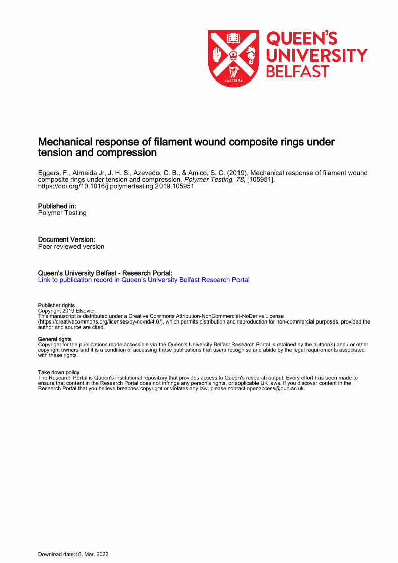
Representative load-displacement curves for all composite rings under axial compression are
shown in Figure 5(a-b). Analogously to radial compression, the closer the winding angle is to the
loading direction, the higher the maximum load achieved. The thinner rings, Figure 5(a), present a
less pronounced maximum peak with a shallow drop in load after that. This suggests that these rings
failed by fiber brooming or crushing at the edges. And the samples buckled at the extremities,
which justifies the observed extended displacement and a slow load drop. The deformed shape at
the maximum load is associated to fairly localized deformations along the specimen and minor
cracks along the fiber direction.
The observed behavior is typical of an elastic shell under axial compression, with a very stable
response in the post-buckling range, which is useful for analyzing the effect of imperfections.
Failure occurs thus by local buckling coupled with matrix failure, characterized by a large curvature
of the specimens, activated by matrix micro-cracks and little fiber breakage. Sambandam et al. [23]
studied the buckling and post-buckling behavior of cylindrical shells and reported that they are
imperfection-sensitive but the buckling phenomenon is not catastrophic, and failure may occur at a
load higher than the buckling load.
For the rings with higher diameter (Figure 5(b)), however, a much clearer load peak is noticed,
with a sharp load drop for all specimens. This takes place because the larger area helps distributing
the load around the shell. The load-displacement curves suggest that these rings fail by
delaminations and intralaminar cracks transversally to the loading direction.
The average axial compressive strength is shown in Figure 5(c). Regardless of the diameter, the
trend is the same, i.e. rings with lower angles present higher axial compressive strength. It is also
valid to mention the low scattering on these results, which is typical of automated processes such as
9
filament winding, where good repeatability is achieved, along with low void content (also due to the
towpreg) and high accuracy in fiber deposition. The imperfections arising from manufacturing also
affect the mechanical response of the structure, and they are particularly difficult to be numerically
modelled.
Figure 5 – Load-displacement curves for the rings with diameters of 50.8 (a) and 136 mm
(b) under axial compression, and calculated compressive strength (c).
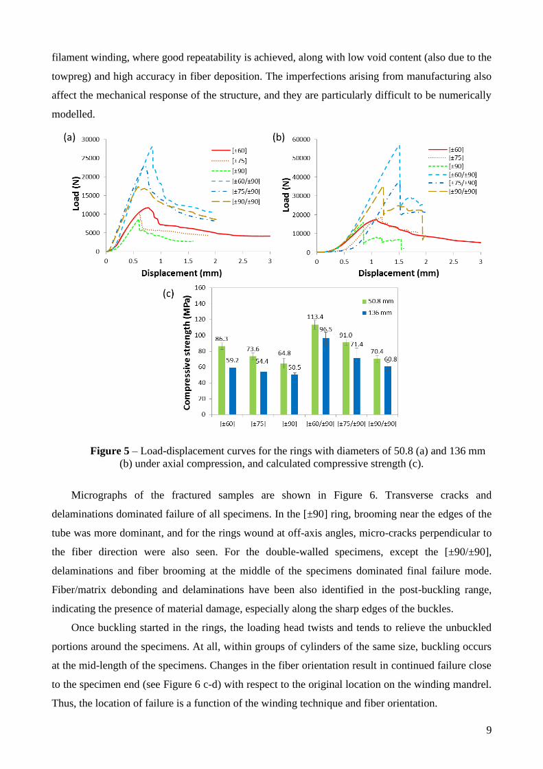
Micrographs of the fractured samples are shown in Figure 6. Transverse cracks and
delaminations dominated failure of all specimens. In the [±90] ring, brooming near the edges of the
tube was more dominant, and for the rings wound at off-axis angles, micro-cracks perpendicular to
the fiber direction were also seen. For the double-walled specimens, except the [±90/±90],
delaminations and fiber brooming at the middle of the specimens dominated final failure mode.
Fiber/matrix debonding and delaminations have been also identified in the post-buckling range,
indicating the presence of material damage, especially along the sharp edges of the buckles.
Once buckling started in the rings, the loading head twists and tends to relieve the unbuckled
portions around the specimens. At all, within groups of cylinders of the same size, buckling occurs
at the mid-length of the specimens. Changes in the fiber orientation result in continued failure close
to the specimen end (see Figure 6 c-d) with respect to the original location on the winding mandrel.
Thus, the location of failure is a function of the winding technique and fiber orientation.
10
Figure 6 – Failure analysis of representative rings after axial compression (diameter: 50.8 mm): (a)
[±60], (b) [±75], (c) [±90], (d) [±60/±90], (e) [±75/±90], (f) [±90/±90].
3.3 Hoop tensile
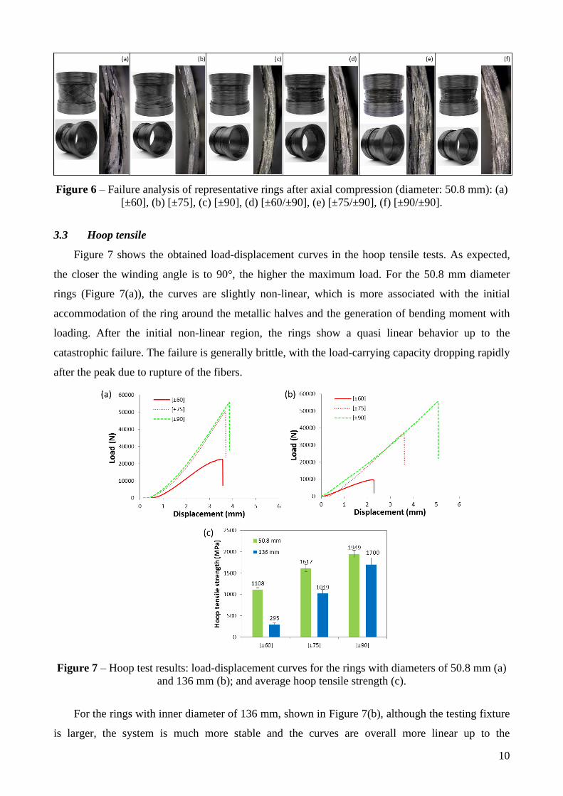
Figure 7 shows the obtained load-displacement curves in the hoop tensile tests. As expected,
the closer the winding angle is to 90°, the higher the maximum load. For the 50.8 mm diameter
rings (Figure 7(a)), the curves are slightly non-linear, which is more associated with the initial
accommodation of the ring around the metallic halves and the generation of bending moment with
loading. After the initial non-linear region, the rings show a quasi linear behavior up to the
catastrophic failure. The failure is generally brittle, with the load-carrying capacity dropping rapidly
after the peak due to rupture of the fibers.
Figure 7 – Hoop test results: load-displacement curves for the rings with diameters of 50.8 mm (a)
and 136 mm (b); and average hoop tensile strength (c).
For the rings with inner diameter of 136 mm, shown in Figure 7(b), although the testing fixture
is larger, the system is much more stable and the curves are overall more linear up to the

11
catastrophic failure. A greater non-linearity at the beginning is observed for the [±75] specimen,
which may be attributed to the high influence of bending at the beginning of the test. This behavior
is, in fact, associated to coupling between the ring and the metallic disks, once the specimen
becomes stiffer as the load increases, which can be identified by the slope between the load-
displacement curve up to 0.5 mm and also afterwards. This is the main reason that justifies the non-
linearity of this sample, which was not observed on the other families of specimens.
The calculated average apparent hoop tensile strength is shown in Figure 7(c). The rings wound
at the circumferential direction presented the highest strength, as expected. For the smaller rings, of
77% increase is seen from [±60] to [±75], followed by 30% increase for the [±90] rings, whereas
for the 136.0 mm rings, the increase in strength was 245% and 67%, respectively. Furthermore, the
apparent hoop tensile strength is higher for cylinders with smaller 𝑑/𝑡 ratios essentially because the
imposed bending moment is more prominent when the ring diameter increases.
Failure type and location for the hoop tensile specimens may be seen in Figure 8. In all
specimens, failure occurred at the gage section driven by the machined notches. Cracks initiated
appearing at the notch tip and then they propagated along the fiber direction. These cracks appeared
at load levels higher than 80% of the maximum bearing load, which are associated to fibers
discontinuity at the edge of the notches, especially for the rings wound in the hoop direction. The
propagation of these cracks progressively isolated the two notches from the rest of the specimen
with the load then carried by the ligament, which eventually failed at the split location. For the
[±60] ring failure initiated with fiber/matrix debonding followed by final catastrophic failure
dominated by fiber breakage (Figure 8(a)). The [±75] ring also presented fiber/matrix debonding,
but failure was more dominated by fiber breakage along the fiber direction. For the hoop laminate,
the catastrophic failure was essentially dominated by fiber breakage. These trends were similar for
the specimens with larger diameters.
Figure 8 – Post-mortem analysis of the rings (diameter: 50.8 mm) after hoop tensile testing.
4. Conclusions
12
This study focused on the experimental evaluation of the influence of diameter-to-thickness
ratio, winding angle and stacking sequence on radial compressive, axial compressive and hoop
tensile properties of carbon fiber reinforced epoxy filament wound composite rings. Under radial
compression, the higher the winding angle, the higher the maximum supported load and stiffness of
the rings with both 50.8 mm and 136 mm. Maximum load and stiffness decreased for rings with
larger 𝑑/𝑡 ratio, and delaminations dominated the failure mode.
Analogously, the lower the winding angle, the higher the axial compressive strength since fiber
orientation is closer to the loading direction. Axial compressive strength was also dependent on the
d/t ratio, but the opposite behavior was observed, i.e. the larger the diameter, the larger the axial
compressive strength. And the rings failed predominantly by delaminations and minor cracks
transverse to the loading direction. Hoop tensile strength was strongly dependent on the winding
angle, and decreased with the 𝑑/𝑡 ratio. Failure was dominated by fiber/matrix debonding followed
by catastrophic fiber breakage, except for the [±90] specimens which predominantly showed fiber
breakage.
Finally, the presented set of tests are enough to determine hoop strengths and compressive
loads when under radial or axial compression appropriately, resulting in well-designed carbon fiber-
reinforced polymer composite cylinders. The proposed hoop tensile and radial/axial compressive
tests possess low cost they may be used in the preliminary design of FW composite tubes as
reference allowing to experimentally evaluate the load bearing capacity of a specific tube system.
Acknowledgments
The authors are grateful to CAPES and CNPq for their financial support; JHS Almeida Jr
thanks Alexander von Humboldt and CAPES Foundations for the CAPES/AvH Fellowship.
References
[1] R. Rafiee, On the mechanical performance of glass-fibre-reinforced thermosetting-resin pipes:
A review, Compos. Struct. 143 (2016) 151–164. doi:10.1016/j.compstruct.2016.02.037.
[2] R. Rafiee, M.A. Torabi, S. Maleki, Investigating structural failure of a filament-wound
composite tube subjected to internal pressure: Experimental and theoretical evaluation, Polym.
Test. 67 (2018) 322–330. doi:10.1016/j.polymertesting.2018.03.020.
[3] J.H.S. Almeida, M.L. Ribeiro, V. Tita, S.C. Amico, Damage and failure in carbon/epoxy
filament wound composite tubes under external pressure: Experimental and numerical
approaches, Mater. Des. 96 (2016) 431–438. doi:10.1016/j.matdes.2016.02.054.
[4] G. Perillo, R. Vacher, F. Grytten, S. Sørbø, V. Delhaye, Material characterisation and failure
envelope evaluation of filament wound GFRP and CFRP composite tubes, Polym. Test. 40
(2014) 54–62. doi:10.1016/j.polymertesting.2014.08.009.
[5] Md. Uddin, E.V. Morozov, K. Shankar, The effect of filament winding mosaic pattern on the
stress state of filament wound composite flywheel disk, Compos. Struct. 107 (2014) 260–275.
doi:10.1016/j.compstruct.2013.07.004.
13
[6] R. Gonzalez, A. McDonald, P. Mertiny, Effect of flame-sprayed Al–12Si coatings on the
failure behaviour of pressurized fibre-reinforced composite tubes, Polym. Test. 32 (2013)
1522–1528. doi:10.1016/j.polymertesting.2013.10.002.
[7] J.H.S. Almeida, S.D.B. Souza, E.C. Botelho, S.C. Amico, Carbon fiber-reinforced epoxy
filament-wound composite laminates exposed to hygrothermal conditioning, J. Mater. Sci. 51
(2016) 4697–4708. doi:10.1007/s10853-016-9787-9.
[8] J.H.S. Almeida, M.L. Ribeiro, V. Tita, S.C. Amico, Damage modeling for carbon fiber/epoxy
filament wound composite tubes under radial compression, Compos. Struct. 160 (2017) 204–
210. doi:10.1016/j.compstruct.2016.10.036.
[9] J.H.S. Almeida, L. Bittrich, E. Jansen, V. Tita, A. Spickenheuer, Buckling optimization of
composite cylinders for axial compression: A design methodology considering a variable-axial
fiber layout, Compos. Struct. 222 (2019) 110928. doi: 10.1016/j.compstruct.2019.110928.
[10] J.H.S. Almeida, C.C. Angrizani, E.C. Botelho, S.C. Amico, Effect of fiber orientation on the
shear behavior of glass fiber/epoxy composites, Mater. Des. 1980-2015. 65 (2015) 789–795.
doi:10.1016/j.matdes.2014.10.003.
[11] J.F. Chen, S.Q. Li, L.A. Bisby, J. Ai, FRP rupture strains in the split-disk test, Compos. Part B
Eng. 42 (2011) 962–972. doi:10.1016/j.compositesb.2010.12.015.
[12] J. Xing, P. Geng, T. Yang, Stress and deformation of multiple winding angle hybrid filament-
wound thick cylinder under axial loading and internal and external pressure, Compos. Struct.
131 (2015) 868–877. doi:10.1016/j.compstruct.2015.05.036.
[13] J.H.S. Almeida, H. Faria, A.T. Marques, S.C. Amico, Load sharing ability of the liner in type
III composite pressure vessels under internal pressure, J. Reinf. Plast. Compos. 33 (2014)
2274–2286. doi:10.1177/0731684414560221.
[14] X. Jia, G. Chen, Y. Yu, G. Li, J. Zhu, X. Luo, C. Duan, X. Yang, D. Hui, Effect of geometric
factor, winding angle and pre-crack angle on quasi-static crushing behavior of filament wound
CFRP cylinder, Compos. Part B Eng. 45 (2013) 1336–1343.
doi:10.1016/j.compositesb.2012.09.060.
[15] P.S. Filho, J.H.S. Almeida, S.C. Amico, Carbon/epoxy filament wound composite drive shafts
under torsion and compression, J. Compos. Mater. 52 (2018) 1103–1111.
doi:10.1177/0021998317722043.
[16] H. Faria, R.M. Guedes, Long-term behaviour of GFRP pipes: Reducing the prediction test
duration, Polym. Test. 29 (2010) 337–345. doi:10.1016/j.polymertesting.2009.12.008.
[17] J.H.S. Almeida, M.L.P. Tonatto, M.L. Ribeiro, V. Tita, S.C. Amico, Buckling and post-
buckling of filament wound composite tubes under axial compression: Linear, nonlinear,
damage and experimental analyses, Compos. Part B Eng. 149 (2018) 227–239.
doi:10.1016/j.compositesb.2018.05.004.
[18] R. Rafiee, Experimental and theoretical investigations on the failure of filament wound GRP
pipes, Compos. Part B Eng. 45 (2013) 257–267. doi:10.1016/j.compositesb.2012.04.009.
[19] C. Kaynak, E. Salim Erdiller, L. Parnas, F. Senel, Use of split-disk tests for the process
parameters of filament wound epoxy composite tubes, Polym. Test. 24 (2005) 648–655.
doi:10.1016/j.polymertesting.2005.03.012.
[20] H. Wang, R. Bouchard, R. Eagleson, P. Martin, W.R. Tyson, Ring hoop tension test (RHTT):
A test for transverse tensile properties of tubular materials, J. Test. Eval. 30 (2002) 382–391.
doi:https://doi.org/10.1520/JTE12328J.
[21] E.V. Morozov, The effect of filament-winding mosaic patterns on the strength of thin-walled
composite shells, Compos. Struct. 76 (2006) 123–129. doi:10.1016/j.compstruct.2006.06.018.
[22] C.B. de Azevedo, F. Eggers, J.H.S. Almeida, S.C. Amico, Effect of the filament winding
pattern modeling on the axial compression of cylindrical shells , in Proceedings of the 4th
Brazilian Conference on Composite Materials. (2018) 554–561.
[23] C.T. Sambandam, B.P. Patel, S.S. Gupta, C.S. Munot, M. Ganapathi, Buckling characteristics
of cross-ply elliptical cylinders under axial compression, Compos. Struct. 62 (2003) 7–17.
doi:10.1016/S0263-8223(03)00079-5.


![Design of Optimum Filament Wound Pressure Vessel with ... · Paper: ASAT-16-082-ST Fukunaga et al. [3] presented two methods for determining the optimum shapes of filament-wound domes](https://img.dokumen.tips/doc/110x75/5b4614d07f8b9a114c8b5bf4/design-of-optimum-filament-wound-pressure-vessel-with-paper-asat-16-082-st.jpg)