Embed Size (px)
Citation preview

MECHANICAL INTEGRITY
TESTING (MIT)
EPA Region 6
Brian Graves
(214) 665-7193
[email protected](Credits to George Robin, Steve Platt & Chuck Tinsley)

USDWs(Underground Sources of
Drinking Water)
Pronounced:

Mechanical Integrity
(MI)Part 1
Internal Mechanical Integrity
40 CFR §146.8(a)(1)
Part 2
External Mechanical Integrity
40 CFR §146.8(a)(2)

146.8 Mechanical integrity.
(a) An injection well has mechanical integrity if:
(Internal)
(1) There is no significant leak in the casing, tubing or packer;
(b) One of the following methods must be used to evaluate the
absence of significant leaks under paragraph (a)(1) of this section:
(1) Following an initial pressure test, monitoring of the tubing-
casing annulus pressure with sufficient frequency to be
representative, as determined by the Director, while
maintaining an annulus pressure different from atmospheric
pressure measured at the surface;
(2) Pressure test with liquid or gas; or

(3) Records of monitoring showing the absence of significant
changes in the relationship between injection pressure and
injection flow rate for the following Class II enhanced recovery
wells:
(i) Existing wells completed without a packer provided that a
pressure test has been performed and the data is available and
provided further that one pressure test shall be performed at a
time when the well is shut down and if the running of such a test
will not cause further loss of significant amounts of oil or gas; or
(ii) Existing wells constructed without a long string casing, but
with surface casing which terminates at the base of fresh water
provided that local geological and hydrological features allow such
construction and provided further that the annular space shall be
visually inspected. For these wells, the Director shall prescribe a
monitoring program which will verify the absence of significant
fluid movement from the injection zone into an USDW.

(a)(2) There is no significant fluid movement into an underground
source of drinking water through vertical channels adjacent to the
injection well bore.
c) One of the following methods must be used to determine the
absence of significant fluid movement under paragraph (a)(2) of
this section:
(1) The results of a temperature or noise log; or
(2) For Class II only, cementing records demonstrating the
presence of adequate cement to prevent such migration; or
(3) For Class III wells where the nature of the casing precludes the
use of the logging techniques prescribed at paragraph (c)(1) of this
section, cementing records demonstrating the presence of
adequate cement to prevent such migration;
(External)

4) For Class III wells where the Director elects to rely on
cementing records to demonstrate the absence of significant
fluid movement, the monitoring program prescribed by
§146.33(b) shall be designed to verify the absence of significant
fluid movement.
(Alternative tests)
(d) The Director may allow the use of a test to demonstrate
mechanical integrity other than those listed in paragraphs (b)
and (c)(2) of this section with the written approval of the
Administrator. To obtain approval, the Director shall submit a
written request to the Administrator, which shall set forth the
proposed test and all technical data supporting its use. The
Administrator shall approve the request if it will reliably
demonstrate the mechanical integrity of wells for which its use is
proposed. Any alternate method approved by the Administrator
shall be published in the FEDERAL REGISTER and may be used in
all States unless its use is restricted at the time of approval by
the Administrator.

(e) In conducting and evaluating the tests enumerated in this
section or others to be allowed by the Director, the owner or
operator and the Director shall apply methods and standards
generally accepted in the industry. When the owner or operator
reports the results of mechanical integrity tests to the Director,
he shall include a description of the test(s) and the method(s)
used. In making his/her evaluation, the Director shall review
monitoring and other test data submitted since the previous
evaluation.
(f) The Director may require additional or alternative tests if the
results presented by the owner or operator under §146.8(e) are
not satisfactory to the Director to demonstrate that there is no
movement of fluid into or between USDWs resulting from the
injection activity.


What are our main MI concerns?
1 Any leaks in the system?

What are our main MI concerns?
1 Any leaks in the system?
2 Is injected fluid entering and
remaining in the approved interval?

What are our main MI concerns?
1 Any leaks in the system?
2 Is injected fluid entering and
remaining in the approved interval?
3 Is there crossflow of fluid into
USDWs?

What are our main MI goals?
1 Any leaks in the system?
(Internal MI)
Goal:
Prevention of leakage through the
“walls” of the well (casing, tubing, etc.)

Prevention of Leakage through the
“walls” of the well (casing, tubing, etc.).
How leakage can be discovered:
• pressure tests

INTERNAL MI ANNULUS PRESSURE TEST
• Tests the tubing, casing and packer for leaks.
• Testing requirements vary by well Class and UIC
program requirements. These vary by State or Tribe.
• Typically the casing/tubing annulus is pressured to
the maximum allowable injection pressure to ensure
the casing can withstand this pressure should the
tubing or packer fail. Director variances can also be
allowed.
• The test length is typically 30 minutes to 1 hour.
• Test failure is typically a pressure loss of > 5 – 10%


Prevention of Leakage through the
“walls” of the well (casing, tubing,
etc.).
How leakage can be discovered:
• pressure tests
• downhole logging (discussed later)

Prevention of Leakage through the
“walls” of the well (casing, tubing, etc.).
How leakage can be discovered:• pressure tests
• downhole logging
• monitoring of injection activities.
– Annulus pressure
– Injection pressure/rate relationship

What are our main MI Goals?
2 Is injected fluid entering and
remaining in the approved interval?
(External MI)
Prevention of Fluid Movement through
Casing/Wellbore Annular Space

What are our main MI Goals?
2 Is injected fluid entering and
remaining in the approved interval?
(External MI)
3 Is there crossflow of fluid into
USDWs?
(External MI)
Prevention of Fluid Movement through
Casing/Wellbore Annular Space

What are our main MI Goals?
Proper cementing and construction
Prevention of Fluid Movement through
Casing/Wellbore Annular Space


Casing
Cementing
Operations

Two-stage Cementing Tools:
(Float Collar, DV tool, and Plugs)

1st - Shut-off Plug
(Ends first stage)2nd - Opening Plug
(Opens DV tool)3rd - Closing Plug
(Closes DV tool)
DV tool @ 4000 ft
Float Collar near TD

Centralizers


Cement
Bond
Log
(CBL)

• Cement needs to set properly before a
cement integrity log is run. This can take from
10 to 50 hours for typical cement jobs.
• Full compressive strength is reached in 7 to
10 days. The setting time depends on the type
of cement, temperature, pressure, and the use
of setting accelerants.
• Excess pressure on the casing should be
avoided during the curing period so that the
cement bond to the pipe is not disturbed.

• Cement bond logs were run as early as 1958 with
early sonic logs and the temperature log was used
to find the cement top beginning in 1933.
• Cement integrity logs are run to determine the
quality of the cement bond to the casing, to
evaluate cement fill-up between the casing and the
wellbore rock and to evaluate the cement bond to
the wellbore rock.
• A poor cement bond may allow unwanted fluids to
enter the wellbore or injected fluid to leave the
injection interval.


Identification of important features on a variable-density log
(VDL) (courtesy of Baker Atlas).

Typical cement-bond log presentation (courtesy of Baker Atlas).

In cases of poor bonding,
casing-collar signals may
also be identified as "w"
patterns (anomalies)

Pressuring the casing improves the acoustic coupling to
the formation and the casing signal will decrease and the
formation signal will become more obvious
Field example showing microannulus effect on amplitude
and VDL log displays (courtesy of Baker Atlas).


CEMENT
EVALUATION
TOOL
(CET)


CET
PURPOSE
• SAME AS CEMENT BOND LOG (CBL)
ONLY MORE ADVANCED PRINCIPLE
• INVESTIGATES CEMENT RADIALLY
• MEASURES CASING DIAMETER, CASING
ROUNDNESS, AND TOOL ECCENTERING

CET
PRINCIPLE OF OPERATION
• ULTRA SONIC ENERGY MAKES CASING
RESONATE
• RATE OF DAMPENING IS MEASURED
• RADIAL INVESTIGATION IS ACHIEVED
WITH 9 TRANSDUCERS

CET
FACTORS AFFECTING MEASUREMENT
• TYPE OF FLUID IN WELL
• THICKNESS OF CASING WALL
• AMOUNT OF CEMENT BONDED TO
CASING
• COMPRESSIVE STRENGTH OF CEMENT

CET
EQUIPMENT
• 8 TRANSDUCERS IN HELICAL PATTERN
• 1 TRANSDUCER (MEASURES FLUID
SOUND VELOCITY)
• TOOL SIZE = 3-3/8 inches to 4 inches

CET
PROCEDURE
• REMOVE TUBING
• ENSURE TOOL IS CENTRALIZED
• LOG ONLY IN LIQUID FILLED CASING
• RUN WITH CASING COLLAR LOCATOR
AND GAMMA RAY

CET
ADVANTAGES
• RADIAL CEMENT EVALUATION
• CEMENT CHANNEL IDENTIFICATION
• IMMUNE TO MICROANNULUS
• NOT AFFECTED BY “FAST FORMATIONS”
• “EASIER” TO INTERPRET


A GOOD
MANUAL
TO HAVE
ON
HAND

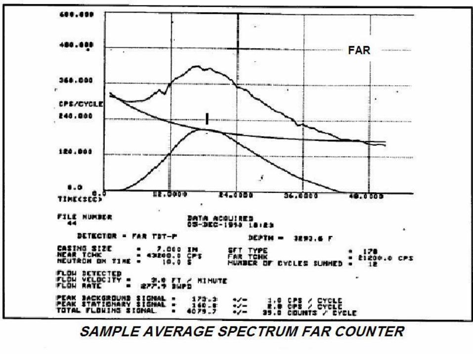
RADIOACTIVE TRACER
SURVEYS
(RATS)

RADIOACTIVE TRACER
SURVEY PURPOSE
• FLOW PROFILING (volumetric)
• DETERMINE FLUID MIGRATION
BOTTOMHOLE CEMENT CHANNELS (Time Drive)
CASING, TUBING, PACKER LEAKS (Internal MI)(Slug Chase)

RATS
OPERATION PRINCIPLES
• USE RADIOACTIVE IODINE (1/2 life = 8 days)
• EJECT TRACER @ surface or downhole
• FOLLOW TRACER as it travels
• USE GAMMA RAY TOOL as detector
• DETECT MIGRATION OF TRACER through tubing
and/or casing

RATS EQUIPMENT
• Radioactive material EJECTOR
Surface or downhole
• 2 or more Gamma Ray DETECTORS
• Ejector/Detector CONFIGURATION varies
depending on objective
• Tool DIAMETER as small as 1-1/2 inches

RATS PROCEDURE• LOAD TRACER at surface
• RUN tool in tubing or casing
• RUN BASE LOG with well on injection
• EJECT tracer at or near surface if running in casing
• EJECT tracer above the packer if in tubing
• FOLLOW tracer to injection zone, while checking for leaks
• LOG ABOVE PERFORATIONS/SCREEN for channels outside casing
• Can check FLOW PROFILE with Spinner
• Run with CASING COLLAR LOCATOR

FACTORS AFFECTING
GAMMA-RAY MEASUREMENT
• RADIOACTIVE (HOT) formations
• INJECTION RATE
• Ejector/Detector CONFIGURATION
• PIPE SCALE


Slug
Chase

RAT tool typically starts here


TIME
DRIVES

RAT tool set here


Leak detected by
lower detector
Leak detected by
upper detector

Flow Profiles

TEMPERATURE
SURVEYS(External MI)

TEMPERATURE SURVEYS
• Oldest of the Production Surveying Instruments (mid 1930s)
• Mercury/piston
• Vapor pressure/bourdon type element (Bottomhole temperature measurements)
• Thermistor – platinum element – resolves temperature changes of 0.05 deg F
» Analog Logging Units
» Digital Logging Units


TEMPERATURE SURVEY
PURPOSE
• LOCATE CEMENT TOPS AFTER PRIMARY
CEMENTING (HEAT FROM EXOTHERMIC
REACTION)
• FLUID MIGRATION DETERMINATION
CASING SHOE BEHIND PIPE
TUBING, CASING, PACKER LEAKS
INTERFORMATIONAL FLUID FLOW
• FLOW (VOLUMETRIC) PROFILING (RARE)
• IDENTIFICATION OF INTERVALS PRODUCING
GAS (COOLING EFFECT FROM EXPANSION)

TEMPERATURE SURVEY
OPERATION PRINCIPLE
• DOWNHOLE TEMPERATURE GOVERNED BY
GEOTHERMAL GRADIENT
• INJECTION OF FLUID WITH LARGE
TEMPERATURE DIFFERENCE (FROM GRADIENT)
• ZONES (OR LEAKS) TAKING INJECTED FLUIDS
WILL RETURN TO GEOTHERMAL GRADIENT AT A
SLOWER RATE

• Since cement gives off heat
as it cures, the temperature
log was used to provide
evidence that the well was
actually cemented to a level
that met expectations. An
example is shown at right.
• The top of cement is located
where the temperature
returns to geothermal
gradient.
• The log must be run during
the cement curing period as
the temperature anomaly will
fade with time.

TEMP SURVEY – A BASIC PROCEDURE
• LET WELL STAND IDLE AT LEAST 24 HOURS
• RUN “BASE LOG” – GEOTHERMAL GRADIENT
• ENSURE INJECTION FLUID TEMPERATURE IS SIGNIFICANTLY DIFFERENT FROM BOTTOM-HOLE TEMPERATURE
• START INJECTION WHILE LOGGING HOLE (OPTIONAL)
• SHUT-IN AFTER PREDETERMINED VOLUME IS INJECTED
• LOG HOLE AFTER 0, 12, AND 24 HOURS SHUT-IN


NOISE LOG(External MI)

NOISE LOG PURPOSE
• TO “HEAR” FLUID FLOW
OCCURRING INSIDE OR OUTSIDE
WELL TUBULARS
BEHIND CASING CHANNELS (water
flow pressure drop OR gas thru liquid)
TUBING AND/OR CASING LEAKS

NOISE LOG
OPERATION PRINCIPLES
• FLUID TURBULENCE (FLOW) - - - NOISE
• NOISE OCCURS OVER A RANGE OF
FREQUENCIES - - TYPICAL TO THE KIND
OF FLOW CREATED
– GAS flow upward thru liquid
»Flows in “bubbles” which “ring”

NOISE LOG
OPERATION PRINCIPLES
• FLUID TURBULENCE (FLOW) - - - NOISE
• NOISE OCCURS OVER A RANGE OF FREQUENCIES - - TYPICAL TO THE KIND OF FLOW CREATED
– FLUID turbulence when forced across constriction – pressure drop

NOISE LOG
OPERATION PRINCIPLES
• FLUID TURBULENCE (FLOW) - - - NOISE
• NOISE OCCURS OVER A RANGE OF FREQUENCIES - - TYPICAL TO THE KIND OF FLOW CREATED
200 Hz (cycles per second)
600 Hz
1000 Hz
2000 Hz

NOISE LOG
EQUIPMENT
• TRANSDUCER (converts sound to electrical signal - to be amplified)
• FREQUENCY SEPARATING FILTERS
• SPEAKER (esp. headphones for operator)
• TYPICAL SIZE = 1¾ inch X 3½ feet (as small as 1 inch O.D.)

NOISE LOG
CHARACTERISTICSESSENTIAL TO INTERPRETATION
• LOUDNESS - measured levels above ambient... amplitude... on all 4 frequencies
- severity of the problem
• CHARACTER – variation in level on a particular cut from station to station is related to the path of flow
- how flow is taking place
• PITCH – frequency content of sound at a peak in noise level
- type of flow (single phase or gas thru liquid)

NOISE LOG
OPERATION GUIDELINES
• Logging Sonde takes readings at different depths while
STATIONARY.
• Log can be utilized in virtually any DOWNHOLE CONDITION
(liquid or gas filled).
• APPLY CRITERIA

NOISE LOG
OPERATION CRITERIA
• Operator consults CONSTRUCTION DETAILS
• WELL SHUT-IN (for behind-pipe flow)
• Record Noise Levels at the 4 FREQUENCIES(200Hz, 600Hz, 1000Hz, 2000Hz)
• MINIMUM READINGS taken opposite the Confining Layer, Base of USDWs and Well Construction changes
• SPACING: readings every 50 to 200 feet (low noise areas); 10 feet or less (zones of interest)
• READING TIMES of 3 or more minutes each

EXAMPLE NOISE LOG
PROCEDURE• PULL TUBING ONLY if necessary
• RUN BASE LOG – well shut-in
• START INJECTION (if necessary to initiate flow)
• RUN NOISE LOG – at same base log stops
• ENSURE TOOL IS STATIONARY at stops
• At ZONES OF INTEREST, perform readings at
10 ft. intervals plus/minus for locating source


OXYGEN ACTIVATIONTRACER SURVEYS
(OA Logs)
(External MI )

OA LOG
PURPOSE
• Determine presence of
FLUID FLOW BEHIND CASING
• Measure
Flow DIRECTION
Linear Flow VELOCITY
Volume Flow RATE ESTIMATE
RADIAL DISTANCE From Tool

OA LOG
PRINCIPLE OF OPERATION
• Similar to Radioactive Tracer Survey
(RATS)
• Tracer is CREATED within the flowing water behind the casing
Water behind pipe is bombarded with ENERGETIC NEUTRONS
Radioactive Nitrogen Isotope with half-life of 7 seconds formed when neutrons react with oxygen in water
• EMMITED GAMMA RAYS detected by two detectors at different distances

OA LOG
LIMITATIONS
• DEPTH OF INVESTIGATION
(approximately 12 inches)
• FLUID COMPOSITION
(must contain Oxygen)
• FLUID VELOCITY

OA LOG EQUIPMENT
• NEUTRON SOURCE
• NEUTRON SHIELD
• 2 GAMMA RAY DETECTORS
above source to detect upward flow
• TOOL SIZES
1-3/4 to 3-5/8 inches X 34 to 26 feet
• COMPUTER ANALYSIS @ surface

OA LOG PROCEDURE
• RUN LOG @ NORMAL INJECTION RATE
• CALIBRATE INSTRUMENT
• RUN BASE GAMMA-RAY LOG
• LOG @ 10 FT. STOPS (5 MIN. EA.)
START BELOW PERFS (NO FLOW)
RELEASE SOURCE
READINGS FOR 5 MINUTES
REPEAT 10 FEET UP HOLE