Embed Size (px)
Citation preview

421
CHAPTER 12REFRIGERATION
Dennis L. O’NealDepartment of Mechanical EngineeringTexas A&M UniversityCollege Station, Texas
1 INTRODUCTION 421
2 BASIC PRINCIPLES 422
3 REFRIGERATION CYCLES ANDSYSTEM OVERVIEW 4233.1 Closed-Cycle Operation 4233.2 Open-Cycle Operation 4263.3 Losses in Refrigeration Cycles 428
4 REFRIGERANTS 4294.1 Regulations on the Production
and Use of Refrigerants 4334.2 Refrigerant Selection for the
Closed Cycle 4344.3 Refrigerant Selection for the
Open Cycle 436
5 ABSORPTION SYSTEMS 4375.1 Water–Lithium Bromide
Absorption Chillers 4375.2 Ammonia–Water Absorption
Systems 440
6 INDIRECT REFRIGERATION 440
7 SYSTEM COMPONENTS 4447.1 Compressors 4447.2 Condensers 4517.3 Evaporators 4527.4 Expansion Devices 454
8 DEFROST METHODS 4598.1 Hot Refrigerant Gas Defrost 4598.2 Air, Electric, and Water Defrost 459
9 SYSTEM DESIGNCONSIDERATIONS 460
10 REFRIGERATION SYSTEMSPECIFICATIONS 461
REFERENCES 463
1 INTRODUCTION
Refrigeration is the use of mechanical or heat-activated machinery for cooling purposes. Theuse of refrigeration equipment to produce temperatures below �150�C is known as cryo-genics.1 When refrigeration equipment is used to provide human comfort, it is called airconditioning. This chapter focuses primarily on refrigeration applications, which cover suchdiverse uses as food processing and storage, supermarket display cases, skating rinks, icemanufacture, and biomedical applications such as blood and tissue storage or hypothermiaused in surgery.
The first patent on a mechanically driven refrigeration system was issued to Jacob Per-kins in 1834 in London.2 The system used ether as the refrigerant. The first viable com-mercial system was produced in 1857 by James Harrison and D. E. Siebe and used ethylether as the refrigerant.2
Refrigeration is used in installations covering a broad range of cooling capacities andtemperatures. While the variety of applications results in a diversity of mechanical specifi-cations and equipment requirements, the methods for producing refrigeration are well stan-dardized.
Mechanical Engineers’ Handbook: Energy and Power, Volume 4, Third Edition.Edited by Myer Kutz
Copyright 2006 by John Wiley & Sons, Inc.

422 Refrigeration
Figure 1 Simple vapor compression refrigeration cycle.3
2 BASIC PRINCIPLES
Most refrigeration systems utilize the vapor compression cycle to produce the desired re-frigeration effect. A less common method used to produce refrigeration is the absorptioncycle, which is described later in this chapter. With the vapor compression cycle, a workingfluid, called the refrigerant, evaporates and condenses at suitable pressures for practicalequipment designs. The ideal (no pressure or frictional losses) vapor compression refriger-ation cycle is illustrated in Fig. 1 on a pressure–enthalpy diagram. This cycle has no pressureloss in the evaporator or condenser, and no heat or frictional losses in the compressor.
There are four basic components in every vapor compression refrigeration system: (1)compressor, (2) condenser, (3) expansion device, and (4) evaporator. The compressor raisesthe pressure of the refrigerant vapor so that the refrigerant saturation temperature is slightlyabove the temperature of the cooling medium used in the condenser. The condenser is a heatexchanger used to reject heat from the refrigerant to a cooling medium. The refrigerant entersthe condenser and usually leaves as a subcooled liquid. Typical cooling mediums used incondensers are air and water. After leaving the condenser, the liquid refrigerant expands to

3 Refrigeration Cycles and System Overview 423
a lower pressure in the expansion valve. The expansion valve can be a passive device, suchas a capillary tube or short tube orifice, or an active device, such as a thermal expansionvalve or electronic expansion valve. At the exit of the expansion valve, the refrigerant is ata temperature below that of the product to be cooled. As the refrigerant travels through theevaporator, it absorbs energy and is converted from a low-quality, two-phase fluid to a su-perheated vapor under normal operating conditions. The vapor formed must be removed bythe compressor at a sufficient rate to maintain the low pressure in the evaporator and keepthe cycle operating.
Pumped recirculation of a liquid secondary refrigerant rather than direct evaporation ofa refrigerant is often used to service remotely located or specially designed heat exchangers.This technique is called indirect refrigeration and provides the user with wide flexibility inapplying refrigeration to complex processes and greatly simplifies operation. Secondary re-frigerants or brines are also commonly used for simple control and operation. Direct appli-cation of ice and brine storage tanks may be used to level off batch cooling loads and reduceequipment size. This approach provides stored refrigeration where temperature control isvital as a safety consideration to prevent runaway reactions or pressure buildup.
All mechanical cooling results in the production of a greater amount of heat energy thancooling energy. In many instances, this heat energy is rejected to the environment directlyto the air in the condenser or indirectly to water where it is rejected in a cooling tower.Under some specialized applications, it may be possible to utilize this heat energy in anotherprocess at the refrigeration facility. This may require special modifications to the condenser.Recovery of this waste heat at temperatures up to 65�C can be used to achieve improvedoperating economy.
Historically, in the United States, capacities of mechanical refrigeration systems havebeen stated in tons of refrigeration, which is a unit of measure related to the ability of anice plant to freeze one short ton (907 kg) of ice in a 24-hr period. A ton is equal to 3.51kW (12,000 Btu/hr).
3 REFRIGERATION CYCLES AND SYSTEM OVERVIEW
Refrigeration can be accomplished in either closed-cycle or open-cycle systems. In a closedcycle, the refrigerant fluid is confined within the system and recirculates through the com-ponents (compressor, heat exchangers, and expansion valve). The system shown at the bottomof Fig. 1 is a closed cycle. In an open cycle, the fluid used as the refrigerant passes throughthe system once on its way to be used as a product or feedstock outside the refrigerationprocess. An example is the cooling of natural gas to separate and condense heavier com-ponents.
In addition to the distinction between open- and closed-cycle systems, refrigerationprocesses are also described as simple cycles, compound cycles, or cascade cycles. Simplecycles employ one set of components (compressor, condenser, evaporator, and expansionvalve) in a single refrigeration cycle as shown in Fig. 1. Compound and cascade cycles usemultiple sets of components and two or more refrigeration cycles. The cycles interact toaccomplish cooling at several temperatures or to allow a greater span between the lowestand highest temperatures in the system than can be achieved with the simple cycle.
3.1 Closed-Cycle Operation
For a simple cycle, the lowest evaporator temperature that is practical in a closed-cyclesystem (Fig. 1) is set by the pressure-ratio capability of the compressor and by the propertiesof the refrigerant. Most high-speed reciprocating compressors are limited to a pressure ratio

424 Refrigeration
Figure 2 Ideal compound refrigeration cycle.3
of 9�1, so that the simple cycle is used for evaporator temperatures from 2 to �50�C. Belowthese temperatures, the application limits of a single-stage compressor are reached. Beyondthat limit, there is a risk of excessively high temperatures at the end of compression, whichmay produce lubricant breakdown, high bearing loads, excessive oil foaming at startup, andinefficient operation because of reduced volumetric efficiency in the compressor.
Centrifugal compressors with multiple stages can generate a pressure ratio up to 18�1,but their high discharge temperatures limit the efficiency of the simple cycle at these highpressure ratios. As a result, they operate with evaporator temperatures in the same range asreciprocating compressors.
The compound cycle (Fig. 2) can achieve temperatures of approximately �100�C byusing two or three compressors in series and a common refrigerant. This keeps the individualcompressors within their application limits. A refrigerant gas cooler (also called a flashintercooler) is normally used between compressors to keep the final discharge temperaturefrom the compressor at a satisfactory level. A common practice is to operate the gas coolerat about the geometric mean of the evaporating and condensing pressures. This providesnearly identical pressure ratios for the two compressors. Besides producing very low tem-peratures, the compound cycle can also be used in applications where multiple evaporatorsare needed to produce different temperatures.
Below �100�C, most refrigerants with suitable evaporator pressures have excessivelyhigh condensing pressures. For some refrigerants, the specific volume of refrigerant at lowtemperatures may be so great as to require compressors and other equipment of uneconomicalsize. With other refrigerants, the specific volume of refrigerant may be satisfactory at lowtemperature, but the specific volume may become too small at the condensing condition. Insome circumstances, although none of the above limitations is encountered and a singlerefrigerant is practical, the compound cycle is not used because of oil-return problems ordifficulties of operation.
To satisfy these conditions, the cascade cycle is used (Fig. 3). This consists of two ormore separate refrigerants, each in its own closed cycle. The cascade condenser–evaporator

3 Refrigeration Cycles and System Overview 425
Figure 3 Ideal cascade refrigeration cycle.3
rejects heat to the evaporator of the high-temperature cycle, which condenses the refrigerantof the low-temperature cycle. Refrigerants are selected for each cycle with pressure–temperature characteristics that are well suited for application at either the higher or lowerportion of the cycle. For extremely low temperatures, more than two refrigerants may becascaded to produce evaporator temperatures at cryogenic conditions (below �150�C). Ex-pansion tanks, sized to handle the low-temperature refrigerant as a gas at ambient temper-atures, are used during standby to hold pressure at levels suitable for economical equipmentdesign.
Compound cycles using reciprocating compressors or any cycle using a multistage cen-trifugal compressor allows the use of economizers or intercoolers between compressionstages. Economizers reduce the discharge gas temperature from the preceding stage by mix-ing relatively cool gas with discharge gas before entering the subsequent stage. Either flash-type economizers, which cool the refrigerant by reducing its pressure to the intermediatelevel, or surface-type economizers, which subcool refrigerant at the condensing pressure,may be used to provide the cooler gas for mixing. This keeps the final discharge gas tem-

426 Refrigeration
perature low enough to avoid overheating of the compressor and improves compressionefficiency.
Compound compression with economizers also affords the opportunity to provide re-frigeration at an intermediate temperature. This provides a further thermodynamic efficiencygain because some of the refrigeration is accomplished at a higher temperature, and lessrefrigerant must be handled by the lower-temperature stages. This reduces the power con-sumption and the size of the lower stages of compression.
Figure 4 shows a typical system schematic with flash-type economizers. Process loadsat several different temperature levels can be handled by taking suction to an intermediatecompression stage as shown. The pressure–enthalpy diagram illustrates the thermodynamiccycle.
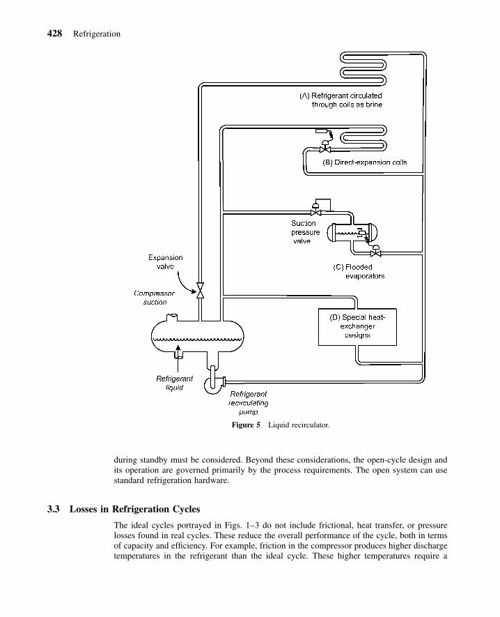
Flooded refrigeration systems are a version of the closed cycle that may reduce designproblems in some applications. In flooded systems, the refrigerant is circulated to heat ex-changers or evaporators by a pump. Figure 5 shows a liquid recirculator, which can use anyof the simple or compound closed-refrigeration cycles.
The refrigerant recirculating pump pressurizes the refrigerant liquid and moves it to oneor more evaporators or heat exchangers, which may be remote from the receiver. The low-pressure refrigerant may be used as a single-phase heat-transfer fluid as in (A) of Fig. 5,which eliminates the extra heat-exchange step and increased temperature difference encoun-tered in a conventional system that uses a secondary refrigerant or brine. This approach maysimplify the design of process heat exchangers, where the large specific volumes of evapo-rating refrigerant vapor would be troublesome. Alternatively, the pumped refrigerant in theflooded system may be routed through conventional evaporators as in (B) and (C), or specialheat exchangers as in (D).
The flooded refrigeration system is helpful when special heat exchangers are necessaryfor process reasons, or where multiple or remote exchangers are required.
3.2 Open-Cycle Operation
In many chemical processes, the product to be cooled can itself be used as the refrigeratingliquid. An example of this is in a natural gas gathering plant. Gas from the wells is cooled,usually after compression and after some of the heavier components are removed as liquid.This liquid may be expanded in a refrigeration cycle to further cool the compressed gas,which causes more of the heavier components to condense. Excess liquid not used for re-frigeration is drawn off as product. In the transportation of liquefied petroleum gas (LPG)and of ammonia in ships and barges, the LPG or ammonia is compressed, cooled, andexpanded. The liquid portion after expansion is passed on as product until the ship is loaded.
Open-cycle operations are similar to closed-cycle operations, except that one or moreparts of the closed cycle may be omitted. For example, the compressor suction may be takendirectly from gas wells, rather than from an evaporator. A condenser may be used, and theliquefied gas may be drained to storage tanks.
Compressors may be installed in series or parallel for operating flexibility or for partialstandby protection. With multiple reciprocating compressors, or with a centrifugal compres-sor, gas streams may be picked up or discharged at several pressures if there is refrigeratingduty to be performed at intermediate temperatures. It always is more economical to refrig-erate at the highest temperature possible.
Principal concerns in the open cycle involve dirt and contaminants, wet gas, compati-bility of materials and lubrication circuits, and piping to and from the compressor. Thepossibility of gas condensing under various ambient temperatures either during operation or

427
Fig
ure
4R
efri
gera
tion
cycl
ew
ithfla
shec
onom
izer
s.3
428 Refrigeration
Figure 5 Liquid recirculator.
during standby must be considered. Beyond these considerations, the open-cycle design andits operation are governed primarily by the process requirements. The open system can usestandard refrigeration hardware.
3.3 Losses in Refrigeration Cycles
The ideal cycles portrayed in Figs. 1–3 do not include frictional, heat transfer, or pressurelosses found in real cycles. These reduce the overall performance of the cycle, both in termsof capacity and efficiency. For example, friction in the compressor produces higher dischargetemperatures in the refrigerant than the ideal cycle. These higher temperatures require a

4 Refrigerants 429
larger condenser to reject heat energy from the cycle. Pressure losses in the evaporator andcondenser require the compressor to work harder to circulate refrigerant in the system. Pre-dicting the performance of a real system must include these effects, or the system capacityand efficiency will be overestimated.
4 REFRIGERANTS
No one refrigerant is capable of providing cost-effective cooling over the wide range oftemperatures and the multitude of applications found in modern refrigeration systems. Am-monia is a popular refrigerant for many industrial and large warehouse applications.4 Bothchlorofluorocarbons (CFCs) and hydrochlorofluorocarbon (HCFC) refrigerants have histori-cally been used in many refrigeration applications, ranging from domestic refrigerators tosupermarket and food storage applications. Most of these refrigerants are generally nontoxicand nonflammable. Recent U.S. federal and international regulations5–7 have placed restric-tions on the production and use of CFCs and HCFCs. Hydrofluorocarbons (HFCs) and HFCmixtures are now being used in some applications where CFCs and HCFCs have been used.Regulations affecting refrigerants are discussed in the next section.
The chemical industry uses low-cost fluids such as propane and butane whenever theyare available in the process. These hydrocarbon refrigerants, often thought of as too hazard-ous because of flammability, are suitable for use in modern compressors, and frequently addno more hazard than already exists in an oil refinery or petrochemical plant. These low-costrefrigerants are used in simple, compound, and cascade systems, depending on operatingtemperatures.
A standard numbering system, shown in Table 1, has been devised to identify refrig-erants without the use of their cumbersome chemical names. There are many popular refrig-erants in the methane and ethane series. These are called halocarbons or halogenatedhydrocarbons because of the presence of halogen elements such as fluorine or chlorine.8
Halocarbons include CFCs, HCFCs, and HFCs.Numbers assigned to the hydrocarbons and halohydrocarbons of the methane, ethane,
propane, and cyclobutane series are such that the number uniquely specifies the refrigerantcompound. The American National Standards Institute (ANSI) and American Society ofHeating, Refrigerating and Air-Conditioning Engineers (ASHRAE) Standard 34-2001 de-scribes the method of coding.9
Zeotropes and azeotropes are mixtures of two or more different refrigerants. A zeotropicmixture changes saturation temperatures as it evaporates (or condenses) at constant pressure.This phenomena is called temperature glide. For example, R-407C has a boiling (bubble)point of �44�C and a condensation (dew) point of �37�C, which means it has a temperatureglide of 7�C. An azeotropic mixture behaves much like a single-component refrigerant inthat it does not change saturation temperatures appreciably as it evaporates or condenses atconstant pressure. Some zeotropic mixtures, such as R-410A, actually have a small enoughtemperature glide (less than 5.5�C) that they are considered a near-azeotropic refrigerantmixture.
Because the bubble-point and dew-point temperatures are not the same for a givenpressure, some zeotropic mixtures have been used to help control the temperature differencesin low-temperature evaporators. These mixture have been used in the lowest stage of someliquified natural gas (LNG) plants.10
Refrigerants are grouped by their toxicity and flammability (Table 2).9,11 Group A1 isnonflammable and least toxic, while group B3 is flammable and most toxic. Toxicity isquantified by the threshold limit value–time weighted average (TLV-TWA), which is the

430 Refrigeration
Table 1 Refrigerant Numbering System (ANSI /ASHRAE 34-2001)a
RefrigerantNumberDesignation Chemical Name
ChemicalFormula
MolecularMass
NormalBoilingPoint,
�CSafetyGroup
Methane Series10 Tetrachloramethane CC14 153.8 77 B111 Trichlorofluoromethane CC13F 137.4 24 A112 Dichlorodifluoromethane CC12F2 120.9 �30 A113 Chlorotrifluoromethane CCIF3 104.5 �81 A122 Chlorodifluoromethane CHCIF2 86.5 �41 A132 Difluoromethane CH2F2 52.0 �52 A250 Methane CH4 16.0 �161 A3
Ethane Series113 1,1,2-Trichlorotrifluoro-ethane CC12FCCIF2 187.4 48 A1114 1,2-Dichlorotetrafluoro-ethane CCIF2CCIF2 170.9 4 A1123 2,2-Dichloro-1,1,1-trifluoroethane CHCL2CF3 152.9 27 B1125 Pentafluoroethane CHF2CF3 120.0 �49 A1134a 1,1,1,2-Tetrafluoroethane CH2FCF3 102.0 �26 A1170 Ethane CH3CH3 30.0 �89 A3
Propane Series290 Propane CH3CH2CH3 44.0 �42 A3
Zeotropes Composition407C R-32 /R-125 /R-134a (23 /25 /52 wt %) 95.0 �44 A1410A R-32 /R-125 (50 /50 wt%) 72.6 �53 A1
Azeotropes Composition500 R-12 /152a (73.8 /26.2 wt %) 99.31 �33 A1502 R-22 /115 (48.8 /51.2 wt %) 112.0 �45 A1
Hydrocarbons600 Butane CH3CH2CH2CH3 58.1600a Isobutane CH(CH3)3 58.1 �12 A3
Inorganic Compounds717 Ammonia NH3 17.0 �33 B2728 Nitrogen N2 28.0 �196 A1744 Carbon dioxide CO2 44.0 �78 A1764 Sulfur dioxide SO2 64.1 �10 B1
Unsaturated Organic Compounds1140 Vinyl chloride CH2—CHCI 62.5 �14 B31150 Ethylene CH2—CH2 28.1 �104 A31270 Propylene CH3CH—CH2 42.1 �48 A3
a Reference 9, reprinted by permission from ASHRAE Standard 34-2001. �American Society of Heating, Refrigerating and Air-ConditioningEngineers, Inc., www.ashrae.org.
upper safety limit for airborne exposure to the refrigerant. If the refrigerant is nontoxic inquantities less than 400 parts per million, then it is a class A refrigerant. If exposure to lessthan 400 parts per million is toxic, then the substance is given the class B designation. Thenumerical designation refers to the flammability of the refrigerant. The last column of Table1 shows the toxicity and flammability rating of many of the common refrigerants.
The A1 group of refrigerants generally fulfills the basic requirements for an ideal re-frigerant, with considerable flexibility as to refrigeration capacity. Many are used for comfortair conditioning since they are nontoxic and nonflammable. These refrigerants are also used

4 Refrigerants 431
Table 2 ANSI /ASHRAE Toxicity and Flammability RatingSystem9
Flammability Group Group
High A3 B3Moderate A2 B2Non A1 B1Threshold limit value
(parts per million)�400 �400
extensively in refrigeration applications. Many CFCs are in the A1 group. With regulationsbanning the production and restricting the sale of all CFCs, the CFCs will eventually ceaseto be used. Common refrigerants in the A1 group include R-11, R-12, R-13, R-22, R-114,R-134a, and R-502.
Refrigerant 11, trichlorofluoromethane, is a CFC. It has a low-pressure–high-volumecharacteristic suitable for use in close-coupled centrifugal compressor systems for water orbrine cooling. Its temperature range extends no lower than �7�C.
Refrigerant 12, dichlorodifluoromethane, is a CFC. It was the most widely known andused refrigerant for U.S. domestic refrigeration and automotive air-conditioning applicationsuntil the early 1990s. It is ideal for close-coupled or remote systems ranging from smallreciprocating to large centrifugal units. It has been used for temperatures as low as �90�C,although �85�C is a more practical lower limit because of the high gas volumes necessaryfor attaining these temperatures. It is suited for single-stage or compound cycles using re-ciprocating and centrifugal compressors.
Refrigerant 13, chlorotrifluoromethane, is a CFC. It is used in low-temperature appli-cations to approximately �126�C. Because of its low volume, high condensing pressure, orboth, and because of its low critical pressure and temperature, R-13 is usually cascaded withother refrigerants at a discharge pressure corresponding to a condensing temperature in therange of �56 to �23�C.
Refrigerant 22, chlorodifluoromethane, is an HCFC. It is used in many of the sameapplications as R-12, but its lower boiling point and higher latent heat permit the use ofsmaller compressors and refrigerant lines than R-12. The higher pressure characteristics alsoextend its use to lower temperatures in the range of �100�C.
Refrigerant 114, dichlorotetrafluoroethane, is a CFC. It is similar to R-11, but its slightlyhigher pressure and lower volume characteristic than R-11 extend its use to �17�C andhigher capacities.
Refrigerant 123, dichlorotrifluoroethane, is an HCFC. It is a replacement refrigerant forR-11 in low-pressure centrifugal chillers. New centrifugal equipment designed for R-123 canprovide exceptionally high energy efficiency. In retrofits of older existing centrifugal chillers,modifications are often needed to increase capacity or avoid material incompatibility (es-pecially elastomers).
Refrigerant 125, pentafluoroethane, is an HFC. It is used in some refrigerant mixtures,including R-407C and R-410A.
Refrigerant 134a, 1,1,1,2-tetrafluoroethane, is an HFC. It is a replacement refrigerantfor R-12 in both refrigeration and air-conditioning applications. It has operating character-istics similar to R-12. R-134a is commonly used in domestic refrigeration applications inthe United States.
Refrigerants 407C and 410A are both mixtures of HFCs. R-407C can be used in someretrofit applications for R-22. Because of its much higher operating pressures, R-410A cannot

432 Refrigeration
be used as a replacement refrigerant in an R-22 system. However, manufacturers have begundesigning new systems that use R-410A, and these systems can be applied in situationswhere R-22 systems were used. The higher operating pressures as well as lubricant incom-patibility with mineral oils has required manufacturers to completely redesign systems withR-410A.
Refrigerant 502 is an azeotropic mixture of R-22 and R-115. Its pressure characteristicsare similar to those of R-22, but it is has a lower discharge temperature.
The B1 refrigerants are nonflammable, but have lower toxicity limits than those in theA1 group. Refrigerant 123, an HCFC, is used in many new low-pressure centrifugal chillerapplications. Industry standards, such as ANSI/ASHRAE Standard 15-1994, provide detailedguidelines for safety precautions when using R-123 or any other refrigerant that is toxic orflammable.11
One of the most widely used refrigerants is ammonia, even though it is moderatelyflammable and has a class B toxicity rating. Ammonia liquid has a high specific heat, anacceptable density and viscosity, and high conductivity. Its enthalpy of vaporization is typ-ically 6–8 times higher than that of the commonly used halocarbons. These properties makeit an ideal heat-transfer fluid with reasonable pumping costs, pressure drop, and flow rates.As a refrigerant, ammonia provides high heat transfer, except when affected by oil attemperatures below approximately �29�C, where oil films become viscous. To limit theammonia-discharge-gas temperature to safe values, its normal maximum condensingtemperature is 38�C. Generally, ammonia is used with reciprocating compressors; althoughrelatively large centrifugal compressors (�3.5 MW), with 8–12 impeller stages required byits low molecular weights, are in use today. Systems using ammonia should contain no copper(with the exception of Monel metal).
The flammable refrigerants (groups A3 and B3) are generally applicable where a flam-mability or explosion hazard is already present and their use does not add to the hazard.These refrigerants have the advantage of low cost. Although they have fairly low molecularweight, they are suitable for centrifugal compressors of larger sizes. Because of the highacoustic velocity in these refrigerants, centrifugal compressors may be operated at high im-peller tip speeds, which partly compensates for the higher head requirements than some ofthe nonflammable refrigerants.
Flammable refrigerants should be used at pressures greater than atmospheric to avoidincreasing the explosion hazard by the admission of air in case of leaks. In designing thesystem, it also must be recognized that these refrigerants are likely to be impure in refrigerantapplications. For example, commercial propane liquid may contain about 2% (by mass)ethane, which in the vapor phase might represent as much as 16–20% (by volume) ethane.Thus, ethane may appear as a noncondensable. Either this gas must be purged or the com-pressor displacement must be increased about 20% if it is recycled from the condenser;otherwise, the condensing pressure will be higher than required for pure propane and thepower requirement will be increased.
Refrigerant 290, propane, is the most commonly used flammable refrigerant. It is wellsuited for use with reciprocating and centrifugal compressors in close-coupled or remotesystems. Its operating temperature range extends to �40�C.
Refrigerant 600, butane, occasionally is used for close-coupled systems in the mediumtemperature range of 2�C. It has a low-pressure and high-volume characteristic suitable forcentrifugal compressors, where the capacity is too small for propane and the temperature iswithin range.
Refrigerant 170, ethane, normally is used for close-coupled or remote systems at �87to �7�C. It must be used in a cascade cycle because of its high-pressure characteristics.

4 Refrigerants 433
Table 3 Comparative Refrigeration Performance of Different Refrigerants at �23�C Evaporating Temperature and �37�CCondensing Temperaturea
RefrigerantNumber Refrigerant Name
EvaporatorPressure(MPa)
CondenserPressure(MPa)
NetRefrigerating
Effect(kJ /kg)
RefrigerantCirculated
(kg /h)
CompressorDisplacement
(L / s)
PowerInput(kW)
11 Trichlorofluoromethane 0.013 0.159 145.8 24.7 7.65 0.29712 Dichlorodifluoromethane 0.134 0.891 105.8 34.0 1.15 0.33022 Chlorodifluoromethane 0.218 1.390 150.1 24.0 0.69 0.326
123 Dichlorotrifluoroethane 0.010 0.139 130.4 27.6 10.16 0.306125 Pentafluoroethane 0.301 1.867 73.7 48.9 0.71 0.444134a Tetrafluoroethane 0.116 0.933 135.5 26.6 1.25 0.345502 R-22 /R-115 azeotrope 0.260 1.563 91.9 39.2 0.72 0.391717 Ammonia 0.166 1.426 1057.4 3.42 0.67 0.310
a Reference 12, reprinted by permission from 2001 ASHRAE Handbook of Fundamentals. �American Society of Heating, Refrigerating andAir-Conditioning Engineers, Inc., www.ashrae.org.
Refrigerant 1150, ethylene, is similar to ethane but has a slightly higher-pressure, lower-volume characteristic, which extends its use to �104 to �29�C. Like ethane, it must be usedin the cascade cycle.
Refrigerant 50, methane, is used in an ultralow range of �160 to �110�C. It is limitedto cascade cycles. Methane condensed by ethylene, which is in turn condensed by propane,is a cascade cycle commonly employed to liquefy natural gas.
Refrigerant 744, carbon dioxide, is currently receiving attention as a possible refrigerantfor use in cooling and refrigeration applications. It has the appeal of being a natural sub-stance. Systems can be designed with R-744, but must operate at elevated pressures. Solidcarbon dioxide (dry ice) is commonly used in the food industry for chilling and freezingapplications.
Table 3 shows the comparative performance of different refrigerants at conditions moretypical of some freezer applications. The data show the relatively large refrigerating effectthat can be obtained with ammonia. Note also that for these conditions, both R-11 and R-123 would operate with evaporator pressures below atmospheric pressure.
4.1 Regulations on the Production and Use of Refrigerants
In 1974, Molina and Rowland published a paper where they put forth the hypothesis thatCFCs destroyed the ozone layer.13 By the late 1970s, the United States and Canada hadbanned the use of CFCs in aerosols. In 1985, Farmer noted a depletion in the ozone layerof approximately 40% over what had been measured in earlier years.4 This depletion in theozone layer became known as the ozone hole. In September 1987, 43 countries signed anagreement called the Montreal Protocol7 in which the participants agreed to freeze CFCproduction levels by 1990, then to decrease production by 20% by 1994 and 50% by 1999.The protocol was ratified by the United States in 1988 and, for the first time, subjected therefrigeration industry to major CFC restrictions.
Recent regulations have imposed restrictions on the production and use of refriger-ants.4,6,14 Production of CFCs in the United States was prohibited after January 1, 1996.14 Aschedule was also imposed that started a gradual phase-out of the production of HCFCs in2004 and will end complete production by 2030. Refrigerants are divided into two classes:

434 Refrigeration
class I, including CFCs, halons, and other major ozone-depleting chemicals; and class II,HCFCs.
Two ratings are used to classify the harmful effects of a refrigerant on the environment.15
The first, the ozone depletion potential (ODP), quantifies the potential damage that the re-frigerant molecule has in destroying ozone in the stratosphere. When a CFC molecule isstruck by ultraviolet light in the stratosphere, a chlorine atom breaks off and reacts withozone to form oxygen and a chlorine/oxygen molecule. This molecule can then react witha free oxygen atom to form an oxygen molecule and a free chlorine. The chlorine can thenreact with another ozone molecule to repeat the process. The estimated atmospheric life ofa given CFC or HCFC is an important factor in determining the value of the ODP. The ODPfor CFC-11 is 1.0. All other ODP values for substances are normalized to that of CFC-11.
The second rating is known as the global warming potential (GWP), which representshow much a given mass of a chemical contributes to global warming over a given timeperiod compared to the same mass of carbon dioxide.16 Carbon dioxide’s GWP is definedas 1.0. The GWP of all other substances is normalized to that of carbon dioxide. Refrigerantssuch as CFCs, HCFCs, and HFCs can block energy from the earth from radiating back intospace. One molecule of R-12 can absorb as much energy as 10,000 molecules of CO2.
Table 4 shows the ODP and GWP for a variety of refrigerants. As a class of refrigerants,the CFCs have the highest ODP and GWP. Because HCFCs tend to be more unstable com-pounds and, therefore, have much shorter atmospheric lifetimes, their ODP and GWP valuesare much smaller than those of the CFCs. All HFCs and their mixtures have zero ODPbecause fluorine does not react with ozone. However, some of the HFCs, such as R-125, R-134a, and R-143a, do have GWP values that are as large or larger than some of the HCFCs.From the standpoint of ozone depletion and global warming, hydrocarbons provide zeroODP and GWP. However, hydrocarbons are flammable, which makes them unsuitable inmany applications.
4.2 Refrigerant Selection for the Closed Cycle
In any closed cycle, the choice of the operating fluid is based on the refrigerant with prop-erties best suited to the operating conditions. The choice depends on a variety of factors,some of which may not be directly related to the refrigerant’s ability to remove heat. Forexample, flammability, toxicity, density, viscosity, availability, and similar characteristics areoften deciding factors. The suitability of a refrigerant also depends on factors such as thekind of compressor to be used (i.e., centrifugal, rotary, or reciprocating), safety in application,heat-exchanger design, application of codes, size of the job, and temperature ranges. Thefactors below should be taken into account when selecting a refrigerant.
Discharge (condensing) pressure should be low enough to suit the design pressure ofcommercially available pressure vessels, compressor casings, etc. However, discharge pres-sure, that is, condenser liquid pressure, should be high enough to feed liquid refrigerant toall the parts of the system that require it.
Suction (evaporating) pressure should be above approximately 3.45 kPa (0.5 psia) fora practical compressor selection. When possible, it is preferable to have the suction pressureabove atmospheric to prevent leakage of air and moisture into the system. Positive pressurenormally is considered a necessity when dealing with hydrocarbons, because of the explosionhazard presented by any air leakage into the system.
Standby pressure (saturation at ambient temperature) should be low enough to suitequipment design pressure, unless there are other provisions in the system for handling therefrigerant during shutdown—for example, inclusion of expansion tanks.

4 Refrigerants 435
Table 4 Ozone Depletion Potential and Halocarbon Global Warming Potential of PopularRefrigerants and Mixturesa
Refrigerant Number Chemical Formula
OzoneDepletionPotential(ODP)
100-yr GlobalWarming Potential
(GWP)
Chlorofluorocarbons11 CCl3F 1.0 4,60012 CCl2F2 1.0 10,600
113 CCl2FCClF2 0.80 14,000114 CClF2CClF2 1.0 9,800115 CClF2CF3 0.6 7,200
Hydrochlorofluorocarbons22 CHClF2 0.055 1,700
123 CHCl2CF3 0.020 120124 CHClFCF3 0.020 620141b CH3CCl2F 0.11 700142b CH3CClF2 0.065 2,400
Hydrofluorocarbons32 CH2F2 0 550
125 CHF2CF3 0 3,400134a CH2FCF3 0 1,100143a CH3CF3 0 750152a CH3CHF2 0 43
Hydrocarbons50 CH4 0 0
290 CH3CH2CH3 0 0Zeotropes
407C R-32 /125 /134a (23 /25 /52%wt) 0 1,700410A R-32 /125 (50 /50%wt) 0 2,000
Azeotropes500 R-12 /152a (73.8 /26.2 wt%) 0.74 6,310502 R-22 /115 (48.8 /51.2 wt%) 0.31 5,494
a Compiled from Refs. 4, 15, and 16.
Critical temperature and pressure should be well above the operating level. As thecritical pressure is approached, less heat is rejected as latent heat compared to the sensibleheat from desuperheating the compressor discharge gas, and cycle efficiency is reduced.Methane (R-50) and chlorotrifluoromethane (R-13) are usually cascaded with other refrig-erants because of their low critical points.
Suction volume sets the size of the compressor. High suction volumes require centrifugalor screw compressors, and low suction volumes dictate the use of reciprocating compressors.Suction volumes also may influence evaporator design, particularly at low temperatures, sincethey must include adequate space for gas-liquid separation.
Freezing point should be lower than minimum operating temperature. This generally isno problem unless the refrigerant is used as a brine.
Theoretical power required for adiabatic compression of the gas is slightly less withsome refrigerants than others. However, this is usually a secondary consideration offset bythe effects of particular equipment selections, for example, line-pressure drops, etc., on sys-tem power consumption.

436 Refrigeration
Vapor density (or molecular weight) is an important characteristic when the compressoris centrifugal because the lighter gases require more impellers for a given pressure rise, thatis, head, or temperature lift. On the other hand, centrifugal compressors have a limitationconnected with the acoustic velocity in the gas, and this velocity decreases with the increas-ing molecular weight. Low vapor densities are desirable to minimize pressure drop in longsuction and discharge lines.
Liquid density should be taken into account. Liquid velocities are comparatively low,so that pressure drop is usually no problem. However, static head may affect evaporatortemperatures, and should be considered when liquid must be fed to elevated parts of thesystem.
Latent heat should be high because it reduces the quantity of refrigerant that needs tobe circulated. However, large flow quantities are more easily controlled because they allowuse of larger, less sensitive throttling devices and apertures.
Refrigerant cost depends on the size of the installation and must be considered bothfrom the standpoint of initial charge, and of composition owing to losses during service.Although a domestic refrigerator contains only a few dollars worth of refrigerant, the refrig-erant in a cooling system for a typical chemical plant may cost thousands of dollars.
Other desirable properties. Refrigerants should be stable and noncorrosive. For heat-transfer considerations, a refrigerant should have low viscosity, high thermal conductivity,and high specific heat. For safety to life or property, a refrigerant should be nontoxic andnonflammable, should not contaminate products in case of a leak, and should have a low-leakage tendency through normal materials of construction.
With a flammable refrigerant, extra precautions have to be taken in the engineeringdesign if it is required to meet the explosion-proof classification. It may be more economicalto use a higher cost, but nonflammable, refrigerant.
4.3 Refrigerant Selection for the Open Cycle
Process gases used in the open cycle include chlorine, ammonia, and mixed hydrocarbons.These gases create a wide variety of operating conditions and corrosion problems. Gas char-acteristics affect both heat exchangers and compressors, but their impact is far more criticalon compressor operation. All gas properties and conditions should be clearly specified toobtain the most economical and reliable compressor design. If the installation is greatlyoverspecified, design features result that not only add significant cost but also complicatethe operation of the system and are difficult to maintain. Specifications should consider thefollowing:
Composition. Molecular weight, enthalpy–entropy relationship, compressibility factor, andoperating pressures and temperatures influence the selection and performance of compressors.If process streams are subject to periodic or gradual changes in composition, the range ofvariations must be indicated.
Corrosion. Special materials of construction and types of shaft seals may be necessary forsome gases. Gases that are not compatible with lubricating oils or that must remain oil-freemay necessitate reciprocating compressors designed with carbon rings or otherwise madeoilless, or the use of centrifugal compressors designed with isolation seals. However, thesefeatures are unnecessary on most installations. Standard designs usually can be used toprovide savings in initial cost, simpler operation, and reduced maintenance.

5 Absorption Systems 437
Dirt and Liquid Carryover. Generally, the carryover of dirt and liquids can be controlledmore effectively by suction scrubbers than by costly compressor design features. Where thisis not possible, all anticipated operating conditions should be stated clearly so that suitablematerials and shaft seals can be provided.
Polymerization. Gases that tend to polymerize may require cooling to keep the gas temper-ature low throughout compression. This can be handled by liquid injection or by providingexternal cooling between stages of compression. Provision may be necessary for internalcleaning with steam.
These factors are typical of those encountered in open-cycle gas compression. Each jobshould be thoroughly reviewed to avoid unnecessary cost, and to obtain the simplest possiblecompressor design for ease of operation and maintenance. Direct coordination between thedesign engineer and manufacturer during final stages of system design is strongly recom-mended.
5 ABSORPTION SYSTEMS
Ferdinand Carre patented the first absorption machine in 1859.2 He employed an ammonia/water solution. His design was soon produced in France, England, and Germany. By 1876,over 600 absorption systems had been sold in the United States. One of the primary usesfor these machines was in the production of ice. During the late 1800s and early 1900s,different combinations of fluids were tested in absorption machines. These included suchdiverse combinations as ammonia with copper sulfate, camphor and naphthol with SO2, andwater with lithium chloride. The modern solution of lithium bromide and water was not usedindustrially until 1940.2
Absorption systems offer three distinct advantages over conventional vapor compressionrefrigeration. First, they do not use CFC or HCFC refrigerants, which are harmful to theenvironment. Second, absorption systems can utilize a variety of heat sources, includingnatural gas, steam, solar-heated hot water, and waste heat from a turbine or industrial process.If the source of energy is from waste heat, absorption systems may provide the lowest costalternative for providing chilled water or refrigeration applications. Third, absorption systemsdo not require any mechanical compression of the refrigerant, which eliminates the need fora lubricant in the refrigerant. Lubricants can decrease heat transfer in evaporators and con-densers.
Two different absorption systems are currently in use. These include (1) a water–lithiumbromide system where water is the refrigerant and lithium bromide is the absorbent and (2)a water–ammonia system where the ammonia is the refrigerant and the water is the absorbent.
Evaporator temperatures ranging from �60� to 10�C are achievable with absorptionsystems.1 For water chilling service, absorption systems generally use water as the refrigerantand lithium bromide as the absorbent solution. For process applications requiring chilledfluid below 7�C, the ammonia–water pair is used with ammonia serving as the refrigerant.
5.1 Water–Lithium Bromide Absorption Chillers
Water–lithium bromide absorption machines can be classified by the method of heat input.Indirect-fired chillers use steam or hot liquids as a heat source. Direct-fired chillers use theheat from the firing of fossil fuels. Heat-recovery chillers use waste gases as the heat source.
438 Refrigeration
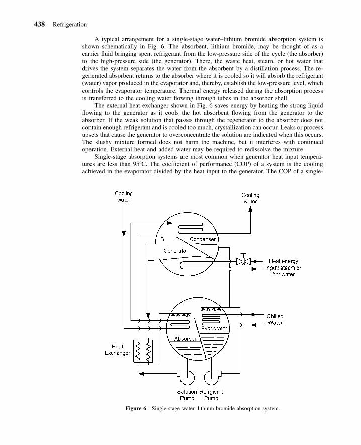
Figure 6 Single-stage water–lithium bromide absorption system.
A typical arrangement for a single-stage water–lithium bromide absorption system isshown schematically in Fig. 6. The absorbent, lithium bromide, may be thought of as acarrier fluid bringing spent refrigerant from the low-pressure side of the cycle (the absorber)to the high-pressure side (the generator). There, the waste heat, steam, or hot water thatdrives the system separates the water from the absorbent by a distillation process. The re-generated absorbent returns to the absorber where it is cooled so it will absorb the refrigerant(water) vapor produced in the evaporator and, thereby, establish the low-pressure level, whichcontrols the evaporator temperature. Thermal energy released during the absorption processis transferred to the cooling water flowing through tubes in the absorber shell.
The external heat exchanger shown in Fig. 6 saves energy by heating the strong liquidflowing to the generator as it cools the hot absorbent flowing from the generator to theabsorber. If the weak solution that passes through the regenerator to the absorber does notcontain enough refrigerant and is cooled too much, crystallization can occur. Leaks or processupsets that cause the generator to overconcentrate the solution are indicated when this occurs.The slushy mixture formed does not harm the machine, but it interferes with continuedoperation. External heat and added water may be required to redissolve the mixture.
Single-stage absorption systems are most common when generator heat input tempera-tures are less than 95�C. The coefficient of performance (COP) of a system is the coolingachieved in the evaporator divided by the heat input to the generator. The COP of a single-

5 Absorption Systems 439
Figure 7 Two-stage water–lithium bromide absorption system.17
stage lithium bromide machine generally is 0.65–0.70 for water-chilling duty. The heat re-jected by the cooling tower from both the condenser and the absorber is the sum of thewaste heat supplied plus the cooling produced, requiring larger cooling towers and coolingwater flows than for vapor compression systems.
Absorption machines can be built with a two-stage generator (Fig. 7) with heat inputtemperatures greater than 150�C. Such machines are called dual-effect machines. The oper-ation of the dual-effect machine is the same as the single-effect machine except that an

440 Refrigeration
additional generator, condenser, and heat exchanger are used. Energy from an external heatsource is used to boil the dilute lithium bromide (absorbent) solution. The vapor from theprimary generator flows in tubes to the second-effect generator. It is hot enough to boil andconcentrate absorbent, which creates more refrigerant vapor without any extra energy input.Dual-effect machines typically use steam or hot liquids as input. Coefficients of performanceabove 1.0 can be obtained with these machines.
5.2 Ammonia–Water Absorption Systems
Ammonia–water absorption technology is used primarily in smaller chillers and small re-frigerators found in recreational vehicles.1 Refrigerators use a variation of the ammoniaabsorption cycle with ammonia, water, and hydrogen as the working fluids. They can befired with both gas and electric heat. The units are hermetically sealed. A complete descrip-tion of this technology can be found in Ref. 1.
Ammonia–water chillers have three major differences from water–lithium bromide sys-tems. First, because the water is volatile, the regeneration of the weak absorbent to strongabsorbent requires a distillation process. In a water–lithium bromide system, the generatoris able to provide adequate distillation because the absorbent material (lithium bromide) isnonvolatile. In ammonia absorption systems, the absorbent (water) is volatile and tends tocarry over into the evaporator where it interferes with vaporization. This problem is overcomeby adding a rectifier to purify the ammonia vapor flowing from the generator to the con-denser.
A second difference between ammonia–water and water–lithium bromide systems is theoperating pressures. In a water–lithium bromide system, evaporating pressures as low as 4–8 kPa are not unusual for the production of chilled water at 5–7�C. In contrast, an ammoniaabsorption system would run evaporator pressures of between 400 and 500 kPa.
A third difference focuses on the type of heat-transfer medium used in the condenserand absorber. Most lithium bromide systems utilize water cooling in the condenser andabsorber, while commercial ammonia systems use air cooling.
6 INDIRECT REFRIGERATION
For indirect refrigeration, the process or refrigeration load is cooled by an intermediate(secondary) liquid, which is itself cooled by refrigerant typically in a conventional vapor-compression cycle (Fig. 8). The secondary liquid can be water, brine, alcohol, or refrigerant.The heat exchanger used to cool the process load may need to be capable of handlingcorrosive products, high pressures, or high viscosities, and is usually not well suited as arefrigerant evaporator. Other problems preventing direct use of a vapor-compression refrig-eration cycle may be remote location, lack of sufficient pressures for the refrigerant liquidfeed, difficulties with oil return, or inability to provide traps in the suction line to hold liquidrefrigerant. Use of indirect refrigeration simplifies the piping system because it becomes aconventional single- phase liquid-system design.
The indirect or secondary coolant (brine) is cooled in the refrigeration evaporator andthen is pumped to the process load. The brine system may include a tank maintained atatmospheric pressure, or may be a closed system pressurized by an inert, dry gas.
Secondary coolants can be separated into four categories:
1. Coolants with a salt base. These are water solutions of various concentrations andinclude the most common brines, that is, calcium chloride and sodium chloride.

6 Indirect Refrigeration 441
Figure 8 Indirect coolant refrigeration system.
2. Coolants with a glycol base. These are water solutions of various concentrations,most commonly ethylene glycol or propylene glycol.
3. Coolants with an alcohol base. Where low temperatures are not required, the alcoholsare occasionally used in alcohol–water solutions.
4. Coolants for low-temperature heat transfer. These usually are pure substances suchas methylene chloride, trichloroethylene, R-11, acetone, and methanol.
Coolants containing a mixture of calcium and sodium chloride are the most commonrefrigeration brines. These are applied primarily in industrial refrigeration and ice skatingrinks. Glycols are used to lower the freezing point of water and used extensively as heat-transfer media in cooling systems. Low-temperature coolants include some common refrig-erants (R-11, R-30, and R-1120). Because R-11 is a CFC, it cannot be used in any newsystems; however, it may still be found in some existing systems. Alcohols and other sec-ondary refrigerants, such as d-limonene (C10H16), are primarily used by the chemical proc-essing and pharmaceutical industries.
A coolant needs to be compatible with other materials in the system where it is applied.It should have a minimum freezing point approximately 8�C below the lowest temperatureto which it is exposed.1 Table 5 shows a performance comparison of different types ofcoolants. Some coolants, such as the salts, glycols, and alcohols, are mixed with water tolower the freezing point of water. Different concentrations than listed in Table 5 will resultin different freezing temperatures. The flow rate divided by capacity gives a way to comparethe amount of flow (L/s) that will be needed to produce a kilowatt of cooling. The low-temperature coolants have the highest flow requirements of the four types of coolants. Theheat-transfer factor is a value normalized to propylene glycol. It is based on calculationsinside a smooth tube. The salt mixtures and R-30 provide the highest heat-transfer factorsof the fluids listed. The energy factor is a measure of the pumping requirements that will beneeded for each of the coolants. The low-temperature fluids require the largest pumpingrequirements.

442 Refrigeration
Table 5 Secondary Coolant Performance Comparisonsa
Secondary Coolant
Concentration(by weight)
%
FreezingPoint(�C)
Flow Rate /Capacity
[L / (s-kW)]b
HeatTransferFactor c
EnergyFactor d
SaltsCalcium chloride 22 �22.1 0.0500 2.761 1.447Sodium chloride 23 �20.6 0.0459 2.722 1.295
GlycolsPropylene glycol 39 �20.6 0.0459 1.000 1.142Ethylene glycol 38 �21.6 0.0495 1.981 1.250
AlcoholsMethanol 26 �20.7 0.0468 2.307 1.078
Low-temperature fluidsMethylene chloride (R-30) 100 �96.7 0.1146 2.854 3.735Trichlorethylene (R-1120) 100 �86.1 0.1334 2.107 4.787Trichlorofluoromethane (R-11) 100 �111.1 0.1364 2.088 5.022d-Limonene 100 �96.7 0.1160 1.566 2.406
a Ref. 1, reprinted by permission from 2002 ASHRAE Handbook of Refrigeration. �American Society of Heating,Refrigerating and Air-Conditioning Engineers, Inc., www.ashrae.org.b Based on inlet secondary coolant temperature at the pump of �3.9�C.c Based on a curve fit of the Sieder & Tate heat-transfer equation values using a 27-mm i.d. tube 4.9 m long and a filmtemperature of 2.8�C lower than the average bulk temperature with a 2.134-m / s velocity. The actual i.d. and lengthvary according to the specific loading and refrigerant applied with each secondary coolant, tube material, and surfaceaugmentation.d Based on the same pump head, refrigeration load, �6.7�C average temperature, 6 K range, and the freezing point (forwater-based secondary coolants) 11 to 13 K below the lowest secondary coolant temperature.
Table 6 shows the general areas of application for the commonly used brines. Criteriafor selection are discussed in the following paragraphs. The order of importance depends onthe specific application.
Corrosion problems with sodium chloride and calcium chloride brines limit their use.When properly maintained in a neutral condition and protected with inhibitors, they willgive 20–30 years of service without corrosive destruction of a closed system. Preventingcorrosions requires proper selection of materials, inhibitors, maintaining a clean system, andregular testing for the pH of the system.1 Glycol solutions and alcohol–water solutions aregenerally less corrosive than salt brines, but they require inhibitors to suit the specific ap-plication for maximum corrosion protection. Methylene chloride, trichloroethylene, and tri-chlorofluoromethane do not show general corrosive tendencies unless they becomecontaminated with impurities such as moisture. However, methylene chloride and trichloro-ethylene must not be used with aluminum or zinc; they also attack most rubber compoundsand plastics. Alcohol in high concentrations will attack aluminum. Reaction with aluminumis of concern because, in the event of leakage into the refrigeration compressor system,aluminum compressor parts will be attacked.
Toxicity is an important consideration in connection with exposure to some productsand to operating personnel. Where brine liquid, droplets, or vapor may contact food products,as in an open spray-type system, sodium chloride and propylene glycol solutions are ac-ceptable because of low toxicity. All other secondary coolants are toxic to some extentor produce odors, which requires that they be used only inside of pipe coils or a similarpressure-tight barrier.

6 Indirect Refrigeration 443
Table 6 Application Information for Common Secondary Coolants1,3
Secondary Coolant Toxic Explosive Corrosive
SaltsCalcium chloride No No YesSodium chloride No No Yes
GlycolsPropylene glycol No No SomeEthylene glycol Yes No Some
AlcoholsMethanol Yes Yes SomeEthanol Yes Yes Some
Low-temperature fluidsMethylene chloride (R-30) No No NoTrichloroethylene (R-1120) No No NoTrichlorofluoromethane (R-11) No No Nod-Limonene Yes Yes Yes
Flash-point and explosive-mixture properties of some coolants require precautionsagainst fire or explosion. Acetone, methanol, and ethanol are in this category but are lessdangerous when used in closed systems.
Specific heat of a coolant determines the mass rate of flow that must be pumped tohandle the cooling load for a given temperature rise. The low-temperature coolants, such astrichloroethylene, methylene chloride, and trichlorofluoromethane, have specific heats ap-proximately one-third to one-fourth those of the water soluble brines. Consequently, a sig-nificantly greater mass of the low-temperature brines must be pumped to achieve the sametemperature change.
Stability at high temperatures is important where a brine may be heated as well ascooled. Above 60�C, methylene chloride may break down to form acid products. Trichlo-roethylene can reach 120�C before breakdown begins.
Viscosities of brines vary greatly. The viscosity of propylene gycol solutions, for ex-ample, makes them impractical for use below �7�C because of the high pumping costs andthe low heat-transfer coefficient at the concentration required to prevent freezing. Mixturesof ethanol and water can become highly viscous at temperatures near their freezing points,but 190-proof ethyl alcohol has a low viscosity at all temperatures down to near the freezingpoint. Similarly, methylene chloride and R-11 have low viscosities down to �73�C. In thisregion, the viscosity of acetone is even more favorable.
Since a secondary coolant cannot be used below its freezing point, certain ones are notapplicable at the lower temperatures. Sodium chloride’s eutectic freezing point of �20�Climits its use to approximately �12�C. The eutectic freezing point of calcium chloride is�53�C, but achieving this limit requires such an accuracy of mixture that �40�C is a practicallow limit of usage.
Water solubility in any open or semi-open system can be important. The dilution of asalt or glycol brine, or of alcohol by entering moisture, merely necessitates strengthening ofthe brine. But for a brine that is not water-soluble, such as trichloroethylene or methylenechloride, precautions must be taken to prevent free water from freezing on the surfaces ofthe heat exchanger. This may require provision for dehydration or periodic mechanical re-moval of ice, perhaps accompanied by replacement with fresh brine.

444 Refrigeration
Vapor pressure is an important consideration for coolants that will be used in opensystems, especially where it may be allowed to warm to room temperature between periodsof operation. It may be necessary to pressurize such systems during periods of moderatetemperature operation. For example, at 0�C the vapor pressure of R-11 is 39.9 kPa (299 mmHg); that of a 22% solution of calcium chloride is only 0.49 kPa (3.7 mm Hg). The cost ofvapor losses, the toxicity of the escaping vapors, and their flammability should be carefullyconsidered in the design of the semi-closed or open system.
Environmental effects are important in the consideration of trichlorofluoromethane (R-11) and other chlorofluorocarbons. This is a refrigerant with a high ozone-depletion potentialand halocarbon global-warming potential. The environmental effect of each of the coolantsshould be reviewed before seriously considering the use of it in a system.
Energy requirements of brine systems may be greater because of the power required tocirculate the brine and because of the extra heat-transfer process, which necessitates themaintenance of a lower evaporator temperature.
7 SYSTEM COMPONENTS
There are four major components in any refrigeration system: compressor, condenser, evap-orator, and expansion device. Each is discussed below.
7.1 Compressors
Both positive displacement and centrifugal compressors are used in refrigeration applications.With positive displacement compressors, the pressure of the vapor entering the compressoris increased by decreasing the volume of the compression chamber. Reciprocating, rotary,scroll, and screw compressors are examples of positive displacement compressors. Centrif-ugal compressors utilize centrifugal forces to increase the pressure of the refrigerant vapor.Refrigeration compressors can be used alone or in parallel and series combinations. Featuresof several of the compressors are described later in this section.
Compressors usually have a variety of protection devices for handling adverse condi-tions. These include high-pressure controls, high-temperature controls, low-pressure protec-tion, time delay, low voltage and phase loss, and suction line strainer.18 High-pressurecontrols are required by Underwriters Laboratories. These can include a high-pressure cutoffor a relief valve. High-temperature devices are designed to protect against overheating andlubrication breakdown. Low-pressure protection is provided to protect the compressor againstextremely low pressures, which may cause insufficient lubricant return, freeze-up, or toohigh a pressure ratio. Time delays are required to prevent damage to the compressor motorfrom rapid startup after a shutdown. A suction line strainer is used to remove dirt and otherparticles that may be in the refrigerant line. The specific protection devices will depend onthe application and size of the compressor.
Reciprocating CompressorsHigh-speed, single-stage reciprocating compressors with displacements up to 0.283–0.472M3 /sec (600–1000 cfm) generally are limited to a pressure ratio of about 9. The reciprocatingcompressor is basically a constant-volume variable-head machine. It handles various dis-charge pressures with relatively small changes in inlet-volume flow rate as shown by theheavy line in Fig. 9.
Reciprocating compressors can also be found in an integral two-stage configuration.18
These can use R-22 or ammonia and can achieve low temperatures from �29 to �62�C.These compressors will consist of multiple cylinders, with the cylinders divided so that the
7 System Components 445
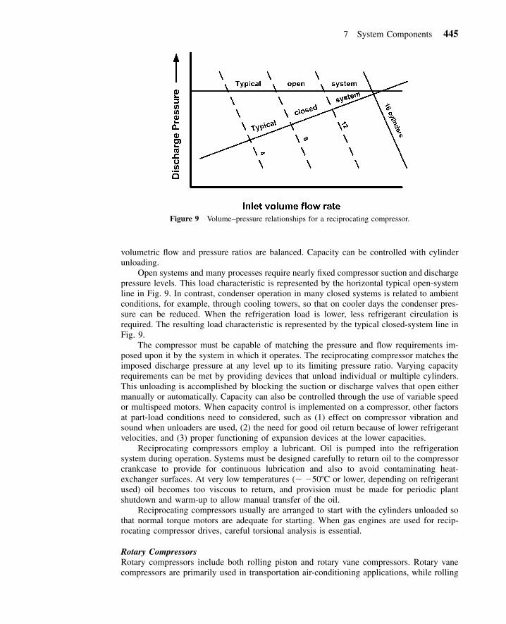
Figure 9 Volume–pressure relationships for a reciprocating compressor.
volumetric flow and pressure ratios are balanced. Capacity can be controlled with cylinderunloading.
Open systems and many processes require nearly fixed compressor suction and dischargepressure levels. This load characteristic is represented by the horizontal typical open-systemline in Fig. 9. In contrast, condenser operation in many closed systems is related to ambientconditions, for example, through cooling towers, so that on cooler days the condenser pres-sure can be reduced. When the refrigeration load is lower, less refrigerant circulation isrequired. The resulting load characteristic is represented by the typical closed-system line inFig. 9.
The compressor must be capable of matching the pressure and flow requirements im-posed upon it by the system in which it operates. The reciprocating compressor matches theimposed discharge pressure at any level up to its limiting pressure ratio. Varying capacityrequirements can be met by providing devices that unload individual or multiple cylinders.This unloading is accomplished by blocking the suction or discharge valves that open eithermanually or automatically. Capacity can also be controlled through the use of variable speedor multispeed motors. When capacity control is implemented on a compressor, other factorsat part-load conditions need to considered, such as (1) effect on compressor vibration andsound when unloaders are used, (2) the need for good oil return because of lower refrigerantvelocities, and (3) proper functioning of expansion devices at the lower capacities.
Reciprocating compressors employ a lubricant. Oil is pumped into the refrigerationsystem during operation. Systems must be designed carefully to return oil to the compressorcrankcase to provide for continuous lubrication and also to avoid contaminating heat-exchanger surfaces. At very low temperatures (� �50�C or lower, depending on refrigerantused) oil becomes too viscous to return, and provision must be made for periodic plantshutdown and warm-up to allow manual transfer of the oil.
Reciprocating compressors usually are arranged to start with the cylinders unloaded sothat normal torque motors are adequate for starting. When gas engines are used for recip-rocating compressor drives, careful torsional analysis is essential.
Rotary CompressorsRotary compressors include both rolling piston and rotary vane compressors. Rotary vanecompressors are primarily used in transportation air-conditioning applications, while rolling

446 Refrigeration
piston compressors are usually found in household refrigerators and small air conditionersup to inputs of 2 kW. For a fixed-vane, rolling piston rotary compressor, the shaft is locatedin the center of the housing while the roller is mounted on an eccentric.8 Suction gas entersdirectly into the suction port. As the roller rotates, the refrigerant vapor is compressed andis discharged into the compressor housing through the discharge valve.
One difference between a rotary and a reciprocating compressor is that the rotary is ableto obtain a better vacuum during suction.18 It has low reexpansion losses because there isno high-pressure discharge vapor present during suction as with a reciprocating compressor.
Because rotary vane compressors have a light weight for their displacement, they areideal for transportation applications. Rotary vane compressors can be used in applicationswhere temperatures drop down to �40 to �51�C, depending whether it is in a single- ortwo-stage system. Refrigerants R-22, R-404a, and R-717 are currently used with rotary vanecompressors.18
Scroll CompressorsThe principle of the scroll compressor was first patented in 1905.19 However, the first com-mercial units were not built until the early 1980s.20 Scroll compressors are used in buildingair-conditioning, heat pump, refrigeration, and automotive air-conditioning applications. Theyrange in capacity from 3 to 50 kW.18 Scroll compressors have two spiral-shaped scroll mem-bers that are assembled 180� out of phase (Fig. 10). One scroll is fixed while the other‘‘orbits’’ the first. Vapor is compressed by sealing vapor off at the edge of the scrolls andreducing the volume of the gas as it moves inward toward the discharge port. Figure 10ashows the two scrolls at the instant that vapor enters the compressor and compression begins.The orbiting motion of the second scroll forces the pocket of vapor toward the dischargeport while decreasing its volume (Fig. 10b–10h). In Fig. 10c and f, the two scrolls open atthe ends and allow new pockets of vapor to be admitted into the scrolls for compression.Compression is a nearly continuous process in a scroll compressor.
Scroll compressors offer several advantages over reciprocating compressors. First, rel-atively large suction and discharge ports can be used to reduce pressure losses. Second, theseparation of the suction and discharge processes reduces the heat transfer between thedischarge and suction processes. Third, with no valves and reexpansion losses, they havehigher volumetric efficiencies. Capacities of systems with scroll compressors can be variedby using variable speed motors or by use of multiple suction ports at different locationswithin the two spiral members. Fourth, with a smaller number of moving parts, they havethe potential to be more reliable and quieter than reciprocating compressors.
Screw CompressorsScrew compressors were first introduced in 1958.2 These are positive displacement machinesavailable in the capacity range from 15 to 1100 kW, overlapping reciprocating compressorsfor lower capacities and centrifugal compressors for higher capacities. Both twin-screw andsingle-screw compressors are used for refrigeration applications.
Fixed suction and discharge ports, used instead of valves in reciprocating compressors,set the ‘‘built-in volume ratio’’ of the screw compressor. This is the ratio of the volume offluid space in the meshing rotors at the beginning of the compression process to the volumein the rotors as the discharge port is first exposed. Associated with the built-in volume ratiois a pressure ratio that depends on the properties of the refrigerant being compressed. Peakefficiency is obtained if the discharge pressure imposed by the system matches the pressuredeveloped by the rotors when the discharge port is exposed. If the interlobe pressure isgreater or less than discharge pressure, energy losses occur but no harm is done to thecompressor.

7 System Components 447
Figure 10 Operation of the fixed and orbiting scrolls in a scroll compressor. (Reprinted by permissionfrom 2000 ASHRAE Handbook of HVAC Systems and Equipment. �American Society of Heating, Re-frigerating, and Air-Conditioning Engineers, Inc., www.ashrae.org.)

448 Refrigeration
Figure 11 Typical performance of a single-screw compressor. (Reprinted by permission from 2000ASHRAE Handbook of HVAC Systems and Equipment. �American Society of Heating, Refrigerating,and Air-Conditioning Engineers, Inc., www.ashrae.org.)
Capacity modulation is accomplished by slide valves that are used to provide a variablesuction bypass or delayed suction port closing, reducing the volume of refrigerant actuallycompressed. Continuously variable capacity control is most common, but stepped capacitycontrol is offered in some manufacturers’ machines. Variable discharge porting is availableon a few machines to allow control of the built-in volume ratio during operation.
Oil is used in screw compressors to seal the extensive clearance spaces between therotors, to cool the machines, to provide lubrication, and to serve as hydraulic fluid for thecapacity controls. An oil separator is required for the compressor discharge flow to removethe oil from the high-pressure refrigerant so that performance of system heat exchangers willnot be penalized and the oil can be returned for reinjection in the compressor.
Screw compressors can be direct driven at two-pole motor speeds (50 or 60 Hz). Theirrotary motion makes these machines smooth running and quiet. Reliability is high when themachines are applied properly. Screw compressors are compact so they can be changed outreadily for replacement or maintenance. Today, the efficiency of the best screw compressorsmatches that of reciprocating compressors at full load. Figure 11 shows the efficiency of asingle-screw compressor as a function of pressure ratio and volume ratio (Vi). High isentropicand volumetric efficiencies can be achieved with screw compressors because there are nosuction or discharge valves and small clearance volumes. Screw compressors have been usedwith a wide variety of refrigerants, including halocarbons, ammonia, and hydrocarbons.
Centrifugal CompressorsThe centrifugal compressor is preferred whenever the gas volume is high enough to allowits use, because it offers better control, simpler hookup, minimum lubrication problems, andlower maintenance. Single-impeller designs are directly connected to high-speed drives or

7 System Components 449
driven through an internal speed increaser. These machines are ideally suited for clean,noncorrosive gases in moderate-pressure process or refrigeration cycles in the range of0.236–1.89 m3 /sec (5 cfm). Multistage centrifugal compressors are built for direct connectionto high-speed drives or for use with an external speed increaser. Designs available fromsuppliers generally provide for two to eight impellers per casing covering the range of 0.236–11.8 m3 /sec (500–25,000 cfm), depending on the operating speed. A wide choice of mate-rials and shaft seals to suit any gas composition, including dirty or corrosive process streams,is available.
The centrifugal compressor has a more complex head-volume characteristic than recip-rocating machines. Changing discharge pressure may cause relatively large changes in inletvolume, as shown by the heavy line in Fig. 12a. Adjustment of variable inlet vanes or of adiffuser ring allows the compressor to operate anywhere below the heavy line to conditionsimposed by the system. A variable-speed controller offers an alternative way to match thecompressor’s characteristics to the system load, as shown in the lower half of Fig. 12b. Themaximum head capability is fixed by the operating speed of the compressor. Both methodshave advantages: generally, variable inlet vanes or diffuser rings provide a wider range ofcapacity reduction; variable speed usually is more efficient. Maximum efficiency and controlcan be obtained by combining both methods of control.
The centrifugal compressor has a surge point—that is, a minimum-volume flow belowwhich stable operation cannot be maintained. The percentage of load at which the surgepoint occurs depends on the number of impellers, design–pressure ratio, operating speed,and variable inlet-vane setting. The system design and controls must keep the inlet volumeabove this point by artificial loading, if necessary. This is accomplished with a bypass–valveand gas recirculation. Combined with a variable inlet-vane setting, variable diffuser ring, orvariable speed control, the gas bypass allows stable operation down to zero load.
Compressor OperationProvision for minimum-load operation is strongly recommended for all installations, becausethere will be fluctuations in plant load. For chemical plants, this permits the refrigerationsystem to be started up and thoroughly checked out independently of the chemical process.
Contrasts between the operating characteristics of the positive displacement compressorand the centrifugal compressor are important considerations in plant design to achieve sat-isfactory performance. Unlike positive displacement compressors, the centrifugal compressorwill not rebalance abnormally high system heads. The drive arrangement for the centrifugalcompressor must be selected with sufficient speed to meet the maximum head anticipated.The relatively flat head characteristics of the centrifugal compressor necessitates differentcontrol approaches than for positive displacement machines, particularly when parallel com-pressors are utilized. These differences, which account for most of the troubles experiencedin centrifugal-compressor systems, cannot be overlooked in the design of a refrigerationsystem.
A system that uses centrifugal compressors designed for high-pressure ratios and thatrequires the compressors to start with high suction density existing during standby will havehigh starting torque. If the driver does not have sufficient starting torque, the system musthave provisions to reduce the suction pressure at startup. This problem is particularly im-portant when using single-shaft gas turbine engines or reduced-voltage starters on electricdrives. Split-shaft gas turbines are preferred for this reason.
Drive ratings that are affected by ambient temperatures, altitudes, etc., must be evaluatedat the actual operating conditions. Refrigeration installations normally require maximumoutput at high ambient temperatures, a factor that must be considered when using drivessuch as gas turbines and gas engines.

450 Refrigeration
Figure 12 Volume–pressure relationships in a centrifugal compressor3: (a) with variable inlet-vanecontrol at constant rotational speed; (b) with variable speed control at a constant inlet-vane opening.

7 System Components 451
Figure 13 Typical shell-in-tube refrigerant condenser.3
7.2 Condensers
The refrigerant condenser is used to reject the heat energy added to the refrigerant duringcompression and the heat energy absorbed in the evaporator. This heat energy is typicallyrejected to either water or air.
The amount of heat energy added to the refrigerant during compression depends on thecompressor power and can become a significant part of the condenser load for low-temperature systems. Common types of water-cooled condensers include shell-and-tube,shell-and-coil, tube-in-tube, and brazed-plate.18 Shell-and-coil condensers are smaller in size(3.5–50 kW) and circulate the cooling water through coiled tubes inside an external shell.The refrigerant condenses on the outside of the coiled tubes. Tube-in-tube condensers canbe found in sizes up to 175 kW and consist of tubes within larger tubes. The refrigerant iscondensed either in the annular space between the tubes or inside the inner tube. Brazed-plate condensers can be found in sizes up to 350 kW and are constructed of plates brazedtogether to form separate channels.18
Shell-and-tube condensers can be found in sizes from 3.5 to 35,000 kW. These con-densers with finned tubes and fixed tube sheets provide an economical exchanger design forrefrigerant use. Figure 13 shows an example of a shell-and-tube condenser. Commerciallyavailable condensers conforming to ASME Boiler and Pressure Vessel Code21 constructionadequately meet both construction and safety requirements for this application.
Cooling towers and spray ponds are frequently used for water-cooling systems. Thesegenerally are sized to provide 29�C supply water at design load conditions. Circulation ratestypically are specified so that design cooling loads are handled with a 5.6�C cooling-watertemperature rise. Pump power, tower fans, makeup water (about 3% of the flow rate), andwater treatment should be taken into account in operating-cost studies. Water temperatures,which control condensing pressure, may have to be maintained above a minimum value toensure proper refrigerant liquid feeding to all parts of the system.
River or well water, when available, provides an economical cooling medium. Quantitiescirculated will depend on initial supply temperatures and pumping cost, but are generallyselected to handle the cooling load with 8.3–16.6�C water-temperature range. Water treatmentand special exchanger materials frequently are necessary because of the corrosive and scale-forming characteristics of the water. Well water, in particular, must be analyzed for corrosiveproperties, with special attention given to the presence of dissolved gases, for example, H2S

452 Refrigeration
and CO2. These are extremely corrosive to many exchanger materials, yet difficult to detectin sampling. Pump power, water treatment, and special condenser material should be eval-uated when considering costs.
Allowances must be made in heat-transfer calculations for fouling or scaling of ex-changer surfaces during operation. This ensures sufficient surface to maintain rated perform-ance over a reasonable interval of time between cleanings. Scale-factor allowances areexpressed in m2 �K/kW as additional thermal resistance.
Commercial practice normally includes a scale-factor allowance of 0.088 m2 �K/kW.The long hours of operation usually associated with chemical-plant service and the type ofcooling water frequently encountered generally justify a greater allowance to minimize thefrequency of downtime for cleaning. Depending on these conditions, an allowance of 0.18or 0.35 m2 �K/kW is recommended for chemical-plant service. Scale allowance can be re-flected in system designs in two ways: as more heat-exchanger surface or as higher designcondensing temperatures with attendant increase in compressor power. Generally, a compro-mise between these two approaches is most economical. For extremely bad water, parallelcondensers, each with 60–100% capacity, may provide a more economical selection andpermit cleaning one exchanger while the system is operating.
Air-cooled condensing equipment can also be used in refrigeration systems. With tighterrestrictions on the use of water, air-cooled equipment is used even on larger centrifugal-typerefrigeration plants, although it requires more physical space than cooling towers. Largercondensers include an array of propeller fans located at the top of the condenser that pullair over the condensing coil. Circulating fans and exchanger surface are usually selected toprovide design condensing temperatures of 49–60�C when design ambient dry bulb temper-atures range between 35 and 38�C.
The design dry bulb temperature should be carefully considered since most weather datareflect an average or mean maximum temperature. If full load operation must be maintainedat all times, care should be taken to provide sufficient condenser capacity for the maximumrecorded temperature. This is particularly important when the compressor is centrifugal be-cause of its flat head characteristics and the need for adequate speed. Multiple-circuit orparallel air-cooled condensers must be provided with traps to prevent liquid backup into theidle circuit at light load. Pressure drop through the condenser coil must also be consideredin establishing the compressor discharge pressure.
The condensing temperature and pressure must be controlled for the refrigeration systemto function optimally. Too high a condensing temperature results in increased power andreduced capacity. Too low a condensing temperature can result in poor performance of theexpansion device. Air-cooled condensers often employ fan cycling, modulating dampers, orfan speed control to maintain proper refrigerant condensing temperature and pressure.18 Oncondensers with multiple fans, one or more of the fans can each be cycled on and off tomaintain refrigerant conditions. When modulating dampers are used, the airflow through thecondenser can be controlled from 0 to 100%. Variable-speed drives can also be used tocontrol fan speed and airflow through the condenser.
In comparing water-cooled and air-cooled condensers, the compression power at designconditions is usually higher with air-cooled condensing, because of the larger temperaturedifferential required in air-cooled condensers. However, ambient air temperatures are con-siderably below the design temperature most of the time, and operating costs frequentlycompare favorably over a full year. In addition, air-cooled condensers usually require lessmaintenance, although dirty or dusty atmospheres may affect performance.
7.3 Evaporators
There are special requirements for evaporators in refrigeration service that are not alwayspresent in other types of heat-exchanger design. These include problems of oil return, flash-gas distribution, gas–liquid separation, and submergence effects.

7 System Components 453
Oil ReturnWhen the evaporator is used with reciprocating-compression equipment, it is necessary toensure adequate oil return from the evaporator. If oil will not return in the refrigerant flow,it is necessary to provide an oil reservoir for the compression equipment and to remove oilmechanically from the low side of the system on a regular basis. Evaporators used withcentrifugal compressors do not normally require oil return from the evaporator, since cen-trifugal compressors pump very little oil into the system. However, even with centrifugalequipment, low-temperature evaporators eventually may become contaminated with oil,which must be reclaimed.
Two-Phase Refrigeration DistributionAs a general rule, the refrigerant is introduced into the evaporator by expanding it from ahigh-pressure liquid through the expansion device. In the expansion process, a significantportion of the refrigerant flashes off into vapor, producing a two-phase mixture of liquid andvapor that must be introduced properly into the evaporator for satisfactory performance.Improper distribution of this mixture can result in liquid carryover to the compressor and indamage to the exchanger tubes from erosion or from vibration.
Vapor–Liquid SeparationTo avoid compressor damage, the refrigerant leaving the evaporator must not contain anyliquid. The design should provide adequate separation space or include mist eliminators.Liquid carryover is one of the most common sources of trouble with refrigeration systems.
Submergence EffectIn flooded evaporators, the evaporating pressure and temperature at the bottom of the ex-changer surface is higher than at the top of the exchanger surface, owing to the liquid head.This static head, or submergence effect, significantly affects the performance of refrigerationevaporators operating at extremely low temperatures and low-suction pressures.
Beyond these basic refrigeration-design requirements, the chemical industry imposesmany special conditions. Exchangers frequently are applied to cool highly corrosive processstreams. Consequently, special materials for evaporator tubes and channels of particularlyheavy wall thickness are dictated. Corrosion allowances in the form of added material thick-nesses in the evaporator may be necessary in chemical service.
High-pressure and high-temperature designs on the process side of refrigerant evapo-rators are frequently encountered in chemical-plant service. Process-side construction mayhave to be suitable for pressures seldom encountered in commercial service. Differencesbetween process inlet and outlet temperatures greater than 55�C are not uncommon. In suchcases, special consideration must be given to thermal stresses within the refrigerant evapo-rator. U-tube construction or floating-tube-sheet construction may be necessary. Minorprocess-side modifications may permit use of less expensive standard commercial fixed-tube-sheet designs. However, coordination between the equipment supplier and chemical-plantdesigner is necessary to tailor the evaporator to the intended duty. Relief devices and safetyprecautions common to the refrigeration field normally meet chemical-plant needs, but shouldbe reviewed against individual plant standards. It must be the mutual responsibility of therefrigeration equipment supplier and the chemical-plant designer to evaluate what specialfeatures, if any, must be applied to modify commercial equipment for chemical-plant service.
Refrigeration evaporators are usually designed to meet the ASME Boiler and PressureVessel Code,21 which provides for a safe, reliable exchanger at economical cost. In refrig-eration systems, these exchangers generally operate with relatively small temperature differ-entials for which fixed-tube-sheet construction is preferred. Operating pressures in refrigerantevaporators also decrease as operating temperatures are reduced. This relationship results in
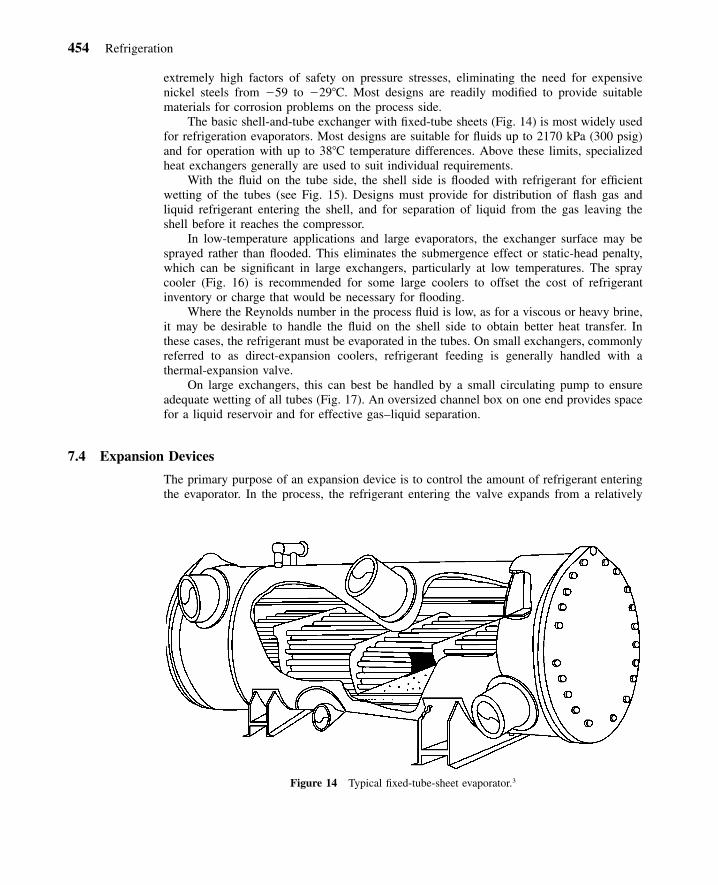
454 Refrigeration
Figure 14 Typical fixed-tube-sheet evaporator.3
extremely high factors of safety on pressure stresses, eliminating the need for expensivenickel steels from �59 to �29�C. Most designs are readily modified to provide suitablematerials for corrosion problems on the process side.
The basic shell-and-tube exchanger with fixed-tube sheets (Fig. 14) is most widely usedfor refrigeration evaporators. Most designs are suitable for fluids up to 2170 kPa (300 psig)and for operation with up to 38�C temperature differences. Above these limits, specializedheat exchangers generally are used to suit individual requirements.
With the fluid on the tube side, the shell side is flooded with refrigerant for efficientwetting of the tubes (see Fig. 15). Designs must provide for distribution of flash gas andliquid refrigerant entering the shell, and for separation of liquid from the gas leaving theshell before it reaches the compressor.
In low-temperature applications and large evaporators, the exchanger surface may besprayed rather than flooded. This eliminates the submergence effect or static-head penalty,which can be significant in large exchangers, particularly at low temperatures. The spraycooler (Fig. 16) is recommended for some large coolers to offset the cost of refrigerantinventory or charge that would be necessary for flooding.
Where the Reynolds number in the process fluid is low, as for a viscous or heavy brine,it may be desirable to handle the fluid on the shell side to obtain better heat transfer. Inthese cases, the refrigerant must be evaporated in the tubes. On small exchangers, commonlyreferred to as direct-expansion coolers, refrigerant feeding is generally handled with athermal-expansion valve.
On large exchangers, this can best be handled by a small circulating pump to ensureadequate wetting of all tubes (Fig. 17). An oversized channel box on one end provides spacefor a liquid reservoir and for effective gas–liquid separation.
7.4 Expansion Devices
The primary purpose of an expansion device is to control the amount of refrigerant enteringthe evaporator. In the process, the refrigerant entering the valve expands from a relatively

7 System Components 455
Figure 15 Typical flooded shell-and-tube evaporator.3
Figure 16 Typical spray-type evaporator.3
high-pressure, subcooled liquid to a saturated low-pressure mixture. Other types of flowcontrol devices, such as pressure regulators and float valves, can also be found in somerefrigeration systems. Discussion of these can be found in Ref. 1. Five types of expansiondevices can be found in refrigeration systems: (1) thermostatic expansion valves, (2) elec-tronic expansion valves, (3) constant-pressure expansion valves, (4) capillary tubes, and (5)short tube restrictors. Each is discussed briefly.
Thermostatic Expansion ValveThe thermostatic expansion valve (TXV) senses the superheat of the gas leaving the evap-orator to control the refrigerant flow into the evaporator. Its primary function is to providesuperheated vapor to the suction of the compressor. A TXV is mounted near the entrance tothe evaporator and has a capillary tube extending from its top that is connected to a smallbulb (Fig. 18). The bulb is mounted on the refrigerant tubing near the evaporator outlet. Thecapillary tube and bulb is filled with a substance called the thermostatic charge.1 This charge

456 Refrigeration
Figure 17 Typical baffled-shell evaporator.3
Figure 18 Cross section of a thermal expansion valve. (Reprinted by permission from 2002 ASHRAEHandbook of Refrigeration. �American Society of Heating, Refrigerating, and Air-Conditioning Engi-neers, Inc., www.ashrae.org.)
often consists of a vapor or liquid that is the same substance as the refrigerant used in thesystem. The response of the TXV and the superheat setting can be adjusted by varying thetype of charge in the capillary tube and bulb.
The operation of a TXV is straightforward. Liquid enters the TXV and expands to amixture of liquid and vapor at pressure P2. The refrigerant evaporates as it travels throughthe evaporator and reaches the outlet where it is superheated. If the load on the evaporator

7 System Components 457
is increased, the superheat leaving the evaporator will increase. This increase in flow willincrease the temperature and pressure (P1) of the charge within the bulb and capillary tube.Within the top of the TXV is a diaphragm. With an increase in pressure of the thermostaticcharge, a greater force is exerted on the diaphragm, which forces the valve port to open andallow more refrigerant into the evaporator. The larger refrigerant flow reduces the evaporatorsuperheat back to the desired level.
The capacity of TXVs is determined on the basis of opening superheat values from 2to 4�C. TXV capacities are published for a range in evaporator temperatures and valvepressure drops. TXV ratings are based on liquid only entering the valve. The presence offlash gas will reduce the capacity substantially.
Electronic Expansion ValveThe electronic expansion valve (EEV) has become popular in recent years on larger or moreexpensive systems where its cost can be justified. EEVs can be heat-motor activated, mag-netically modulated, pulse-width modulated, and step-motor driven.1 EEVs can be used withdigital control systems to provide control of the refrigeration system based on input variablesfrom throughout the system.
Constant-Pressure Expansion ValveA constant-pressure expansion valve controls the mass flow of the refrigerant entering theevaporator by maintaining a constant pressure in the evaporator. Its primary use is for ap-plications where the refrigerant load is relatively constant. It is usually not applied wherethe refrigeration load may vary widely. Under these conditions, this expansion valve willprovide too little flow to the evaporator at high loads and too much flow at low loads.
Capillary TubeCapillary tubes are used extensively in household refrigerators, freezers, and small air con-ditioners. The capillary tube consists of one or more small-diameter tubes, which connectthe high-pressure liquid line from the condenser to the inlet of the evaporator. Capillary tubesrange in length from 1 to 6 m and diameters from 0.5 to 2 mm.17
After entering a capillary tube, the refrigerant remains a liquid for some length of thetube (Fig. 19). While a liquid, the pressure drops, but the temperature remains relativelyconstant (from point 1 to 2 in Fig. 19). At point 2, the refrigerant enters into the saturationregion where a portion of the refrigerant begins to flash to vapor. The phase change accel-erates the refrigerant and the pressure drops more rapidly. Because the mixture is saturated,its temperature drops with the pressure from 2 to 3. In many applications, the flow througha capillary tube is choked, which means that the mass flow through the tube is independentof downstream pressure.17
Because there are no moving parts to a capillary tube, it is not capable of making directadjustments to variations in suction pressure or load. Thus, the capillary tube does not pro-vide as good as performance as TXVs when applied in systems that will experience a widerange in loads.
Even though the capillary tube is insensitive to changes in evaporator pressure, its flowrate will adjust to changes in the amount of refrigerant subcooling and condenser pressure.If the load in the condenser suddenly changes so that subcooled conditions are no longermaintained at the capillary-tube inlet, the flow rate through the capillary tube will decrease.The decreased flow will produce an increase in condenser pressure and subcooling.
The size of the compressor, evaporator, and condenser as well as the application (re-frigerator or air conditioner) must all be considered when specifying the length and diameterof capillary tubes. Systems using capillary tubes tend to be much more sensitive to the

458 Refrigeration
Figure 19 Typical temperature and pressure distribution in a capillary tube. (Reprinted by permissionfrom 2002 ASHRAE Handbook of Refrigeration. �American Society of Heating, Refrigerating, and Air-Conditioning Engineers, Inc., www.ashrae.org.)
Figure 20 Schematic of a short-tube restrictor. (Reprinted by permission from 2002 ASHRAE Hand-book of Refrigeration. �American Society of Heating, Refrigerating, and Air-Conditioning Engineers,Inc., www.ashrae.org.)
amount of refrigerant charge than systems using TXVs or EEVs. Design charts for capillarytubes can be found in Ref. 1 for R-12 and R-22.
Short-Tube RestrictorShort-tube restrictors are applied in many systems that formerly used capillary tubes. Figure20 illustrates a short-tube restrictor and its housing. The restrictors are inexpensive, reliable,and easy to replace. In addition, for systems such as heat pumps, which reverse cycle, short-tube restrictors eliminate the need for a check valve. Short-tubes vary in length from 10 to

8 Defrost Methods 459
13 mm, with a length-to-diameter ratio from 3 to 20.1 Current applications for short-tuberestrictors are primarily in air conditioners and heat pumps.
Like a capillary tube, short-tube restrictors operate with choked or near-choked flow inmost applications.22 The mass flow through the orifice is nearly independent of conditionsdownstream of the orifice. The flow rate does vary with changes in the condenser subcoolingand pressure.
In applying short-tube restrictors, there are many similarities to capillary tubes. The sizeof the system components and type of system must be considered when sizing this expansiondevice. Sizing charts for the application of short-tube restrictors with R-22 can be found inRef. 23.
8 DEFROST METHODS
When refrigeration systems operate below 0�C for extended periods of time, frost can formon the heat-transfer surfaces of the evaporator. As frost grows, it begins to block the airflowpassages and insulates the cold refrigerant from the warm/moist air that is being cooled bythe refrigeration system. With increasing blockage of the airflow passages, the evaporatorfan(s) are unable to maintain the design airflow through the evaporator. As airflow drops,the capacity of the system decreases, and eventually reaches a point where the frost mustbe removed. This is accomplished with a defrost cycle.
Several defrost methods are used with refrigeration systems: hot refrigerant gas, air, andwater. Each method can be used individually or in combination with the other.
8.1 Hot Refrigerant Gas Defrost
This method is the most common technique for defrosting commercial and industrial refrig-eration systems. When the evaporator needs defrosting, hot gas from the discharge of thecompressor is diverted from the condenser to the evaporator by closing control valve 2 andopening control valve 1 in Fig. 21. The hot gas increases the temperature of the evaporatorand melts the frost. Some of the hot vapor condenses to liquid during the process. A specialtank, such as an accumulator, can be used to protect the compressor from any liquid returningto the compressor.
During defrost operation, the evaporator fans are turned off, which increases the evap-orator coil temperature faster. With the fans off, the liquid condensate drains from the coilfaster and helps minimize the thermal load to the refrigerated space during defrost. In someinstances, electrical heaters are added to increase the speed of the defrost.
Defrost initiation is usually accomplished via demand defrost or time-initiated defrost.Demand-defrost systems utilize a variable, such as pressure drop across the air side of theevaporator or a set of temperature inputs, to determine if frost has built up enough on thecoil to require a defrost. Time-initiated defrost relies on a preset number of defrosts per day.The number of defrosts and length of time of each defrost can be adjusted. Ideally, thedemand–defrost system provides the most efficient defrost controls on a system, because adefrost is only initiated if the evaporator needs it. Termination of the defrost cycle is accom-plished by either a fixed-time interval or a set temperature of the coil.
8.2 Air, Electric, and Water Defrost
If the refrigerated space operates above 0�C, then the air in the space can be used directlyto defrost the evaporator. Defrost is accomplished by continuing to operate the evaporator

460 Refrigeration
Figure 21 Simplified diagram of a hot-refrigerant-gas defrost system.
blower while the compressor is off. As the frost melts, some of it is evaporated into theairstream while the rest drains away from the coil as liquid water. The evaporated moistureadds an additional load to the evaporator when the compressor starts again.
Electric heat can be applied to the evaporator via a heating element. This technique isusually slower than hot-gas defrost. The heating element can be in direct contact with theevaporator or be located between the fan and evaporator.1
Water can also be used to defrost the evaporator. The compressor and fans are shut offwhile water is sprayed over the evaporator. If the velocity of the water is kept high, it washesor melts the frost off the coil.
9 SYSTEM DESIGN CONSIDERATIONS
Associated with continuous operation are refrigeration startup and shutdown conditions thatinvariably differ, sometimes widely, from those of the process itself. These conditions, al-though they occupy very little time in the life of the installation, must be properly accom-modated in the design of the refrigeration system. Consideration must be given to the amountof time required to achieve design operating conditions, the need for standby equipment,etc.
In batch processing, operating conditions are expected to change with time, usually ina repetitive pattern. The refrigeration system must be designed for all extremes. Use of brinestorage or ice banks can reduce equipment sizes for batch processes.

10 Refrigeration System Specifications 461
Closed-cycle operation involves both liquid and gas phases. System designs must takeinto account liquid-flow problems in addition to gas-flow requirements and must provide foreffective separation of the liquid and gas phases in different parts of the system. These factorsrequire careful design of all components and influence the arrangement or elevation of certaincomponents in the cycle.
Liquid pressures must be high enough to feed liquid to the evaporators at all times,especially when evaporators are elevated or remotely located. In some cases, a pump mustbe used to suit the process requirements. The possibility of operation with reduced pressurescaused by colder condensing temperatures than the specified design conditions must also beconsidered. Depending on the types of liquid valves and relative elevation of various partsof the system, it may be necessary to maintain condensing pressures above some minimumlevel, even if doing so increases the compression power.
Provision must be made to handle any refrigerant liquid that can drain to low spots inthe system upon loss of operating pressure during shutdown. It must not be allowed to returnas liquid to the compressor upon startup.
The operating charge in various system components fluctuates depending on the load.For example, the operating charge in an air-cooled condenser is quite high at full load, butis low, that is, essentially dry, at light load. A storage volume such as a liquid receiver mustbe provided at some point in the system to accommodate this variation. If the liquid controlspermit the evaporator to act as the variable storage, the level may become too high, resultingin liquid carry over to the compressor.
Abnormally high process temperatures may occur either during startup or process upsets.Provision must be made for this possibility, for it can cause damaging thermal stresses onrefrigeration components and excessive boiling rates in evaporators, forcing liquid to carryover and damage the compressor.
Factory-designed-and-built packages, which provide cooling as a service or utility, canrequire several thousand kilowatts of power to operate, but in most cases, they require nomore installation than connection of power, utilities, and process lines. As a result, there isa single source of responsibility for all aspects of the refrigeration cycle involving the transferand handling of both saturated liquids and saturated vapors throughout the cycle, oil return,and other design requirements. These packages are custom engineered, including selectionof components, piping, controls, base designs, torsional and critical speed analysis, andindividual chemical process requirements. Large packages are designed in sections for ship-ment, but are readily interconnected in the field.
As a general rule, field-erected refrigeration systems should be close-coupled to mini-mize problems of oil return and refrigerant condensation in suction lines. Where processloads are remotely located, pumped recirculation or brine systems are recommended. Pipingand controls should be reviewed with suppliers to assure satisfactory operation under allconditions.
10 REFRIGERATION SYSTEM SPECIFICATIONS
To minimize costly and time-consuming alterations owing to unexpected requirements, therefrigeration specialist who is to do the final design must have as much information aspossible before the design is started. Usually, it is best to provide more information thanthought necessary , and it is always wise to note where information may be sketchy, missing,or uncertain. Carefully spelling out the allowable margins in the most critical process vari-ables and pointing out portions of the refrigeration cycle that are of least concern is alwayshelpful to the designer. A checklist of minimum information (Table 7) needed by a refrig-eration specialist to design a cooling system for a particular application may be helpful.

462 Refrigeration
Table 7 Information Needed for the Design of a Refrigeration System
Process flow sheets and thermal specificationsType of process
BatchContinuous
Normal heat balancesNormal material balancesNormal material compositionDesign operating pressure and temperaturesDesign refrigeration loadsEnergy recovery possibilitiesManner of supplying refrigeration (primary or secondary)
Basic specificationsMechanical system details
Construction standardsIndustryCompanyLocal plant
Insulation requirementsSpecial corrosion prevention requirementsSpecial sealing requirements
Process streams to the environmentProcess stream to refrigerant
Operating environmentIndoor or outdoor locationExtremesSpecial requirements
Special safety considerationsKnown hazards of processToxicity and flammability constraintsMaintenance limitations
Reliability requirementsEffect of loss of cooling on process safetyMaintenance intervals and types that may be performed
Redundancy requirementAcceptance test requirements
Instrumentation and control requirementsSafety interlocksProcess interlocksSpecial control requirements
At equipmentCentral control room
Special or plant standard instrumentsDegree of automation: interface requirementsIndustry and company control standards
Off-design operationProcess startup sequence
Degree of automationRefrigeration loads vs. timeTime needed to bring process on-streamFrequency of startupProcess pressure, temperature, and composition changes during startupSpecial safety requirements
Minimum loadNeed for standby capability

References 463
Table 7 (Continued )
Peak-load pressures and temperaturesComposition extremesProcess shutdown sequence
Degree of automationRefrigeration load vs. timeShutdown time spanProcess pressure, temperature, and composition changesSpecial safety requirements
Process Flow Sheets. For chemical process designs, seeing the process flow sheets is thebest overall means for the refrigeration engineer to become familiar with the chemical proc-ess for which the refrigeration equipment is to be designed. In addition to providing all ofthe information shown in Table 7, they give the engineer a feeling for how the chemicalplant will operate as a system and how the refrigeration equipment fits into the process.
Basic Specifications. This portion of Table 7 fills in the detailed mechanical information thattells the refrigeration engineer how the equipment should be built, where it will be located,and specific safety requirements. This determines which standard equipment can be used andwhat special modifications need to be made.
Instrumentation and Control Requirements. These tell the refrigeration engineer how thesystem will be controlled by the plant operators. Particular controller types, as well as controlsequencing and operation, must be spelled out to avoid misunderstandings and costly rede-sign. The refrigeration engineer needs to be aware of the degree of control required for therefrigeration system—for example, the process may require remote starting and stopping ofthe refrigeration system from the central control room. This could influence the way in whichthe refrigeration safeties and interlocks are designed.
Off-design Operation. It is likely that the most severe operation of the refrigeration systemwill occur during startup and shutdown. The rapidly changing pressures, temperatures, andloads experienced by the refrigeration equipment can cause motor overloads, compressorsurging, or loss of control if they are not anticipated during design.
REFERENCES
1. ASHRAE Handbook of Refrigeration, American Society of Heating, Refrigerating and Air-Conditioning Engineers, Atlanta, 2002.
2. R. Thevenot, A History of Refrigeration Throughout the World, International Institute of Refrigera-tion, Paris, France, 1979, pp. 39–46.
3. K. W. Cooper and K. E. Hickman, ‘‘Refrigeration’’ in Encyclopedia of Chemical Technology, Vol.20, 3rd ed., Wiley, New York, 1984, pp. 78–107.
4. C. E. Salas and M. Salas, Guide to Refrigeration CFC’s, Fairmont Press, Liburn, GA, 1992.5. U.S. Environmental Protection Agency, ‘‘The Accelerated Phaseout of Ozone-Depleting Sub-
stances,’’Federal Register, 58(236), 65018–65082 (December 10, 1993).6. U.S. Environmental Protection Agency, ‘‘Class I Nonessential Products Ban, Section 610 of the
Clean Air Act Amendments of 1990,’’ Federal Register 58(10), 4768–4799 (January 15, 1993).7. United Nations Environmental Program (UNEP), Montreal Protocol on Substances That Deplete the
Ozone Layer—Final Act, 1987.

464 Refrigeration
8. G. King, Basic Refrigeration, Business News, Troy, MI, 1986.9. ANSI /ASHRAE 34-2001, Number Designation and Safety Classification of Refrigerants, American
Society of Heating, Refrigerating and Air-Conditioning Engineers, Atlanta, 2001.10. G. G. Haselden, Mech. Eng., 44 (March 1981).11. ANSI /ASHRAE 15-1994, Safety Code for Mechanical Refrigeration, American Society of Heating,
Refrigerating and Air-Conditioning Engineers, Atlanta, 1994.12. ASHRAE Handbook of Fundamentals, American Society of Heating, Refrigerating and Air-
Conditioning Engineers, Atlanta (Chapter 19), 2001.13. M. J. Molina and F. S. Rowland, ‘‘Stratospheric Sink for Chlorofluoromethanes: Chlorine Atoms
Catalyzed Destruction of Ozone,’’ Nature, 249, 810–812 (1974).14. C. D. MacCracken, ‘‘The Greenhouse Effect on ASHRAE,’’ ASHRAE Journal, 31(6), 52–55 (1996).15. U.S. EPA, Ozone Depletion Website, http: / /www.epa.gov /ozone / index.html, United States Environ-
mental Protection Agency, 2004.16. Houghton et al., Climate Change 2001: The Scientific Basis, Cambridge University Press, Cam-
bridge, UK, 2001.17. W. F. Stoecker and J. W. Jones, Refrigeration and Air Conditioning, 2nd ed., McGraw-Hill, New
York, 1982.18. ASHRAE Handbook of HVAC Systems and Equipment, American Society of Heating, Refrigerating
and Air-Conditioning Engineers, Atlanta, 2000, Chapters 34 and 35.19. K. Matsubara, K. Suefuji, and H. Kuno, ‘‘The Latest Compressor Technologies for Heat Pumps in
Japan,’’ in Heat Pumps, K. Zimmerman and R. H. Powell, Jr. (eds.), Lewis, Chelsea, MI, 1987.20. T. Senshu, A. Araik, K. Oguni, and F. Harada, ‘‘Annual Energy-Saving Effect of Capacity-Modulated
Air Conditioner Equipped with Inverter-Driven Scroll Compressor,’’ ASHRAE Transactions, 91(2)(1985).
21. ASME Boiler and Pressure Vessel Code, Sect. VIII, Div. 1, The American Society of MechanicalEngineers, New York, 1980.
22. Y. Kim and D. L. O’Neal, ‘‘A Comparison of Critical Flow Models for Estimating Two-Phase Flowof HCFC 22 and HFC 134a Through Short Tube Orifices,’’ International Journal of Refrigeration,18(6) (1995).
23. Y. Kim and D. L. O’Neal, ‘‘Two-Phase Flow of Refrigerant-22 through Short-Tube Orifices,’’ASHRAE Transactions, 100(1) (1994).