Embed Size (px)
Citation preview

Mechanical Engineering Systems CapstoneUniversal Proofloader
Brenda HathcockSam Jones
Kevin Tierney

Agenda
• Systems Engineering Process• Problem • Solution
• Requirements Definition• Conceptual Design• Detailed Design
• Cost/Capability

Systems Engineering Process

Systems EngineeringProcess
System Level Requirements Definition
System Level Architecting
System Level Detailed Design
Sub‐System Level
Requirements DefinitionSub‐System
Level Architecting
Subs CDR
Sub‐System Level Detailed Design
System CDR
System Integration &
Testing
Sub‐System Integration, Testing,
Verification
System Verification & Validation
Need Need Satisfied
Component Procurement /
Mfg & Verification

Problem Definition
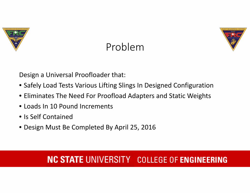
Problem
Design a Universal Proofloader that:• Safely Load Tests Various Lifting Slings In Designed Configuration• Eliminates The Need For Proofload Adapters and Static Weights• Loads In 10 Pound Increments• Is Self Contained• Design Must Be Completed By April 25, 2016

What is a Sling?

What is Proofloading and Why?
• Loading Slings to Test Reliability• Must be done
• At Manufacture• After Major Structural Repair

Problem
Design a Universal Proofloader that:• Safely Load Tests Various Lifting Slings In Designed Configuration• Eliminates The Need For Proofload Adapters and Static Weights• Loads In 10 Pound Increments• Is Self Contained• Design Must Be Completed By April 25, 2016

Requirements Definition
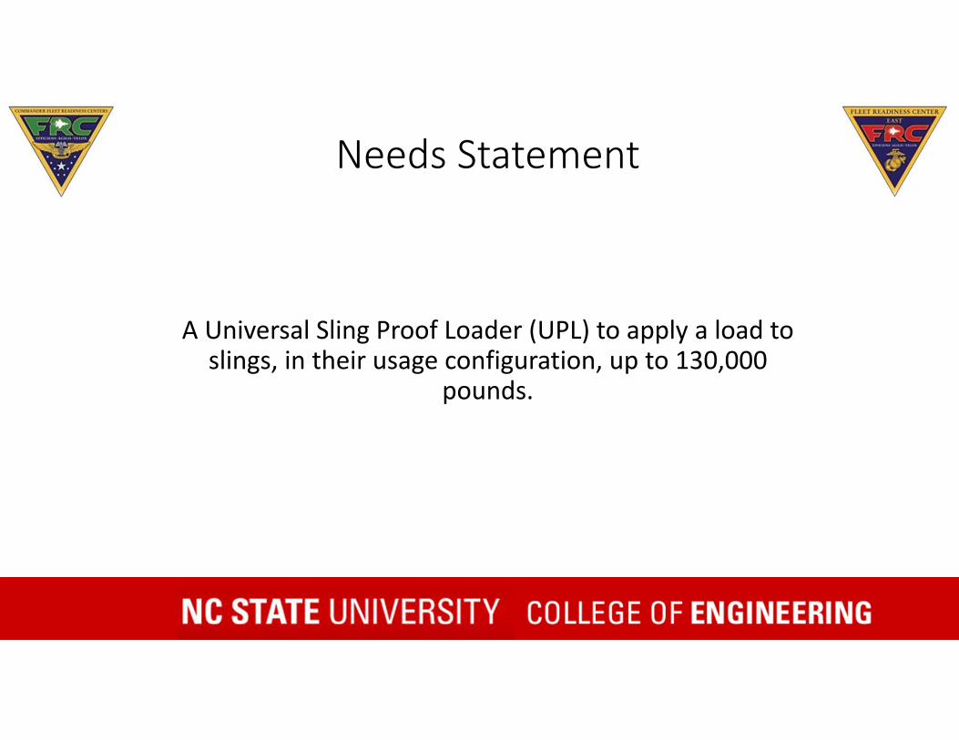
Needs Statement
A Universal Sling Proof Loader (UPL) to apply a load to slings, in their usage configuration, up to 130,000
pounds.
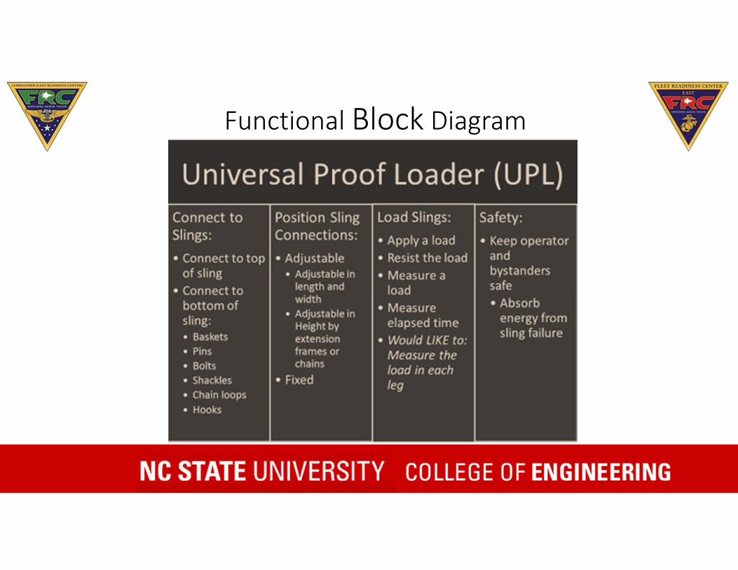
Functional Block Diagram

Current Proofloading Capabilities
• Calculated method for prooftesting slings with dead weights, up to 6,000 lbs.
• Straight pulls up to 120,000 lbs.

Database
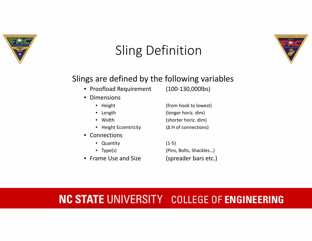
Sling Definition
Slings are defined by the following variables• Proofload Requirement (100‐130,000lbs)• Dimensions
• Height (from hook to lowest)• Length (longer horiz. dim)• Width (shorter horiz. dim)• Height Eccentricity (Δ H of connections)
• Connections• Quantity (1‐5)• Type(s) (Pins, Bolts, Shackles…)
• Frame Use and Size (spreader bars etc.)

Sling Dimensions• Height
(from hook to lowest)• Length
(longer horiz. dim)• Width
(shorter horiz. dim)• Height Eccentricity
(Δ H of connections)

Sling Size ConsiderationsSlings below set the size of the Universal Proofloader (UPL)
38’x25’x17’ 96,000 lbsMax Length and Width
E‐216’x7’x20’ 46,800 lbs
Max Height
H‐60
H

Connection Point Plots

Sling Connections
Pins, 20.3%
Bolts, 18.0%
Shackles, 13.3%
Basket Loops, 13.0%
Hooks, 7.3%
Chain Loops, 0.3%
Something Else, 15.7%
Combination, 12.0%

Sling Proofload Requirements
0‐10,000 lbswere placed in 1,000 lbbins.
10,000 lbs + were put in 10,000 lbbins.
Requirements
Nee
dR
eq#
Sub-
Req
#
Description
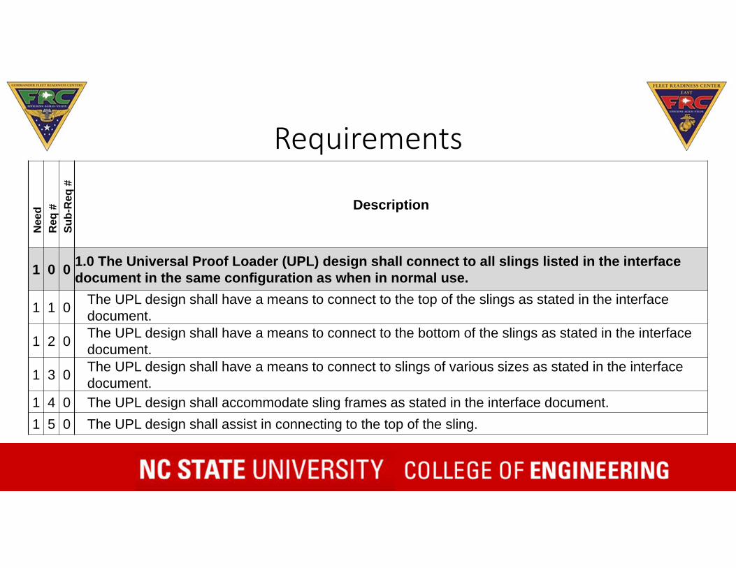
1 0 0 1.0 The Universal Proof Loader (UPL) design shall connect to all slings listed in the interface document in the same configuration as when in normal use.
1 1 0 The UPL design shall have a means to connect to the top of the slings as stated in the interface document.
1 2 0 The UPL design shall have a means to connect to the bottom of the slings as stated in the interface document.
1 3 0 The UPL design shall have a means to connect to slings of various sizes as stated in the interface document.
1 4 0 The UPL design shall accommodate sling frames as stated in the interface document.1 5 0 The UPL design shall assist in connecting to the top of the sling.

Specifications
• 130,000 lbs. on 4 legs• 97,500 lbs. on 3 legs• 65,000 lbs. on 2 legs• 130,000 lbs. straight pull• 40‐90⁰ from horizontal• 0‐25⁰ from plane of leg

• Safety• Reliability• Percentage Loaded• Connection Accuracy• Turn Around Time • Cost
Measures of Effectiveness

Importance of the Systems
Engineering Process

From Concept to Design

Individual Concepts

Initial Concept Developed
Inspiration
Option A
Option B
Option C
Option D
Final Concept

Final Concept(but not final design)

Final Design
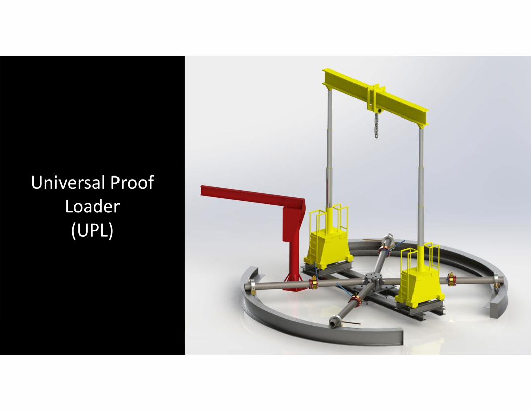
Universal Proof Loader(UPL)

SlingUniversal Proof
Loader(UPL)
Notes:
Sling Part Number Used On R1 θ1 R2 θ2 R3 θ3 R4 θ4
1128SME40001-3 EA-6 36.5 56.3 36.5 56.3 36.5 56.3 36.5 56.3
65720-70018-041 H-53 64.3 51.8 57.6 61.2 77.3 69.8 82.2 61.9
901-220-933-103 V-22 34.9 32.2 34.9 32.2 31.9 22.3 31.9 22.3
75D110000 AV-8 33.4 31.6 33.4 31.6 49.5 68.3 49.5 68.3Connections 3 and 4 use
adapter #1.
Connection 1
Connection 2
Connection 3
Connection 4

Universal Proof Loader(UPL)
Sling

Universal Proof Loader(UPL)
Sling

Universal Proof Loader(UPL)

Universal Proof Loader(UPL)


Detailed Design

Detailed Design• What is detailed design?
• Stresses• Safety Factor• Ease of use• Manufacturing• Drawings
UPL 42-1NONESHEET
1 9
A
B
C
D
NORTH CAROLINA STATE UNIVERSITY SCALE SIZE DWG. NO.A
REV.
DATE
KJTIERNEYDRAWN
P.O. BOX 7801, Raleigh, North Carolina 1 : 10
8
4 APR 2016
7
DIMENSIONS ARE IN INCHESUNLESS OTHERWISE SPECIFIED
TOLERANCES ARE:FRACTIONS DECIMALS ANGLES
.5 .005
MATERIAL
12345678
THE INFORMATION CONTAINED IN THIS DRAWING IS THE SOLE PROPERTY OFNC STATE UNIVERSITY. ANY REPRODUCTION IN PART OR WHOLE WITHOUTTHE WRITTEN PERMISSION OF NC STATE UNIVERSITY IS PROHIBITED.
ADJUSTER 42
A
B
C
D
123456
1/32 .XX .01 .XXX
OF
186X
(PN UPL-42-1)
2X 12
2
4
11
3
2X
19
6X 19
ADJUSTER-42
6X
6X 17
214X
22 2 0KVE6 98380A702 PIN .375 X 2.00 SS21 4 0KVE6 92620A655 BOLT .375-28UNF X 1.00 GR 820 4 0KVE6 9657K367 SPRING, COMPRESSION19 12 0KVE6 90126A038 WASHER18 6 0KVE6 94895A855 HEX NUT GR 817 6 0KVE6 91257A989 BOLT 1.00-14UNF X 4.00 GR 816 2 0KVE6 98381A843 PIN .750 X 2.00 SS15 6 0KVE6 90126A037 WASHER14 6 0Z629 67511964 BOLT .875-14UNF X 6.00 GRADE L913 1 0KVE6 1103K31 ZERK, GREASE12 2 -12 SHELL LOCK11 2 -11 SHELL HALF10 1 -10 LOCKING RING9 2 -9 WEDGE HALF8 1 -8 LOOP BOTTOM7 1 -7 LOOP LOOP6 1 -6 LOOP TOP5 1 -5 LOOP TOP WELDMENT4 1 -4 LOCKING RING ASSY3 1 -3 COLLET-WEDGE ASSY2 1 -2 LOOP ASSY1 UPL-42-1 ADJUSTER-42
ITEMNO.
-5REQD
-4REQD
-3REQD
-2REQD
-1REQD DAI PART NO. DESCRIPTION MATERIAL MATERIAL SPEC & NO.
PARTS LIST
NOTES:
1. REMOVE ALL BURRS AND BREAK ALL SHARP EDGES.
2. ADJUSTER MUST BE ASSEMBLED IN PLACE ON LEG-TUBE.
3. HARD CHROME PLATE .02 MIN THICKNESS ON INNER BEARING SURFACE AREA.
4. DESIGN FACTOR OF SAFETY IS 3:1 TO YIELD AND 5:1 TO ULTIMATE STRENGTH.
5. HEAT TREAT IN ACCORDANCE WITH AMS 2759.
6. SUGGESTED SOURCES OF SUPPLY ARE NOT A GUARANTEE OF AVAILABILITY.

Process
Desired End Product
Brenda’s Subsystem
Kevin’s Subsystem
Sam’s Subsystem
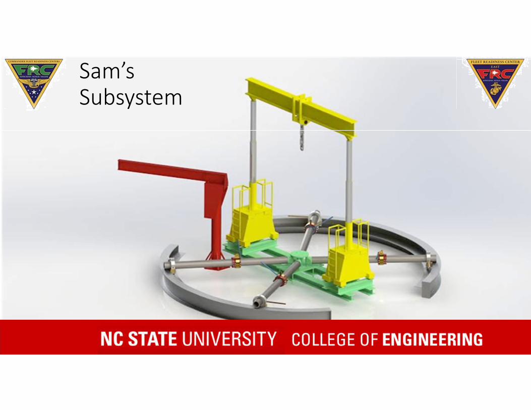
Sam’s Subsystem

Pin Adapter
• Reduces total number of adapters• Previously made out of 4130 steel

Adapters – Pins Calculations
3.5” Radius
D
L
VC
H
F1x
F2x
S/N
Pin Diameter
(in) D
Length (in) L
Inner Ta
Width (in) W
Bearing Stress (psi)
Safety Factor
(Ultimate)
Tab Height (in) H
abs
65720‐700787‐041 0.64 1.277T101897 0.625 0.760
1 ‐779 77.03 1.91 ‐5,182 11.58 1.8
T101610 0.563 0.180 1 ‐5,905 10.16 1.765720‐70005‐041 0.453 0.880CPWA30804 0.437 0.6256798116 0.4 0.25570700‐77408‐046 0.312 2.5076797692 0.311 0.64165700‐70020‐041 0.261 1.647
1 ‐1,357 44.20 1.41 ‐2,331 25.74 1.31 ‐6,241 9.61 1.31 ‐1,058 56.71 1.01 ‐12,781 4.69 1.01 ‐1,333 45.02 0.9

Adapters – Pins Calculations
b
h
Fillet Weld
• If a one inch weld is used around the base of each tab, the minimum strength needed in the weld is 16,000 psi
• This force is well under the strength of the weld material that will be used.
S/NBase
Perimeter
Weld Thickness
(in)Weld Area (in^2) PSI
Weld Material Strength
(U) Load for 5:165720‐700787‐041 4.554 1 0.5 439 586 2,928T101897 3.52 1 0.5 2,197 2,929 14,646T101610 2.36 1 0.5 797 1,062 5,31165720‐70005‐041 3.76 1 0.5 452 603 3,014CPWA30804 3.25 1 0.5 615 821 4,1036798116 2.51 1 0.5 797 1,062 5,31270700‐77408‐046 7.014 1 0.5 371 494 2,4716797692 3.28125 1 0.5 2,438 3,251 16,25465700‐70020‐041 5.294 1 0.5 340 453 2,267

Center Structure

Center Structure130,000 lbs
• The load is transferred down to I‐Beams that push up against the feet of the gantries.
• This enables the gantry system to pull against itself, creating a self contained system.
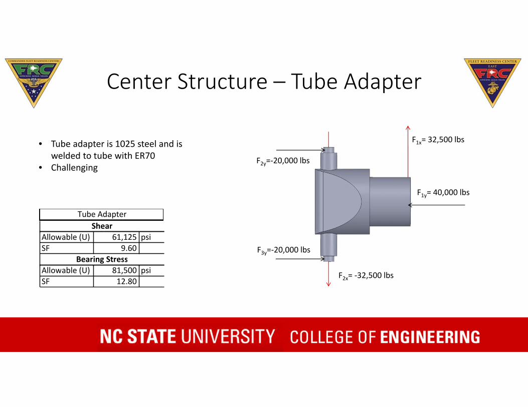
Center Structure – Tube Adapter
F1x= 32,500 lbs
F2x= ‐32,500 lbs
F2y=‐20,000 lbs
F3y=‐20,000 lbs
F1y= 40,000 lbs
• Tube adapter is 1025 steel and is welded to tube with ER70
• Challenging
Tube AdapterShear
Allowable (U) 61,125 psiSF 9.60
Bearing StressAllowable (U) 81,500 psiSF 12.80

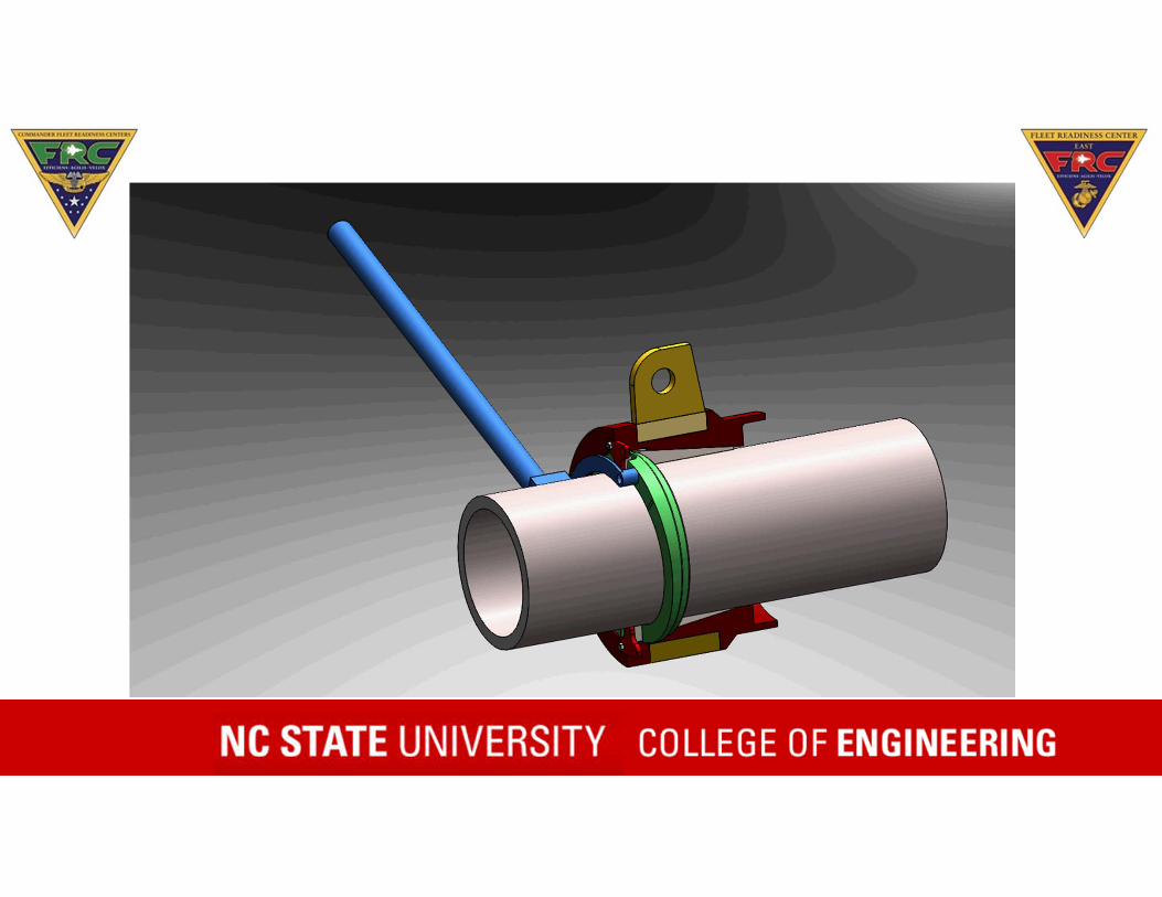
Kevin’s Adjuster Design


Brenda’s Sub‐System


Cam Mechanism

Cost
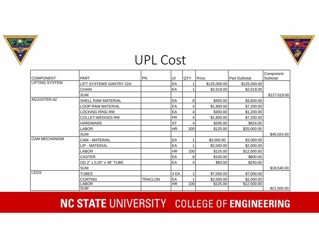
UPL CostCOMPONENT PART PN UI QTY Price Part Subtotal
Component Subtotal
LIFT SYSTEMS GANTRY 22A EA 1 $125,000.00 $125,000.00CHAIN EA 1 $2,619.00 $2,619.00SUMSHELL RAW MATERIAL EA 8 $450.00 $3,600.00LOOP RAW MATERIAL EA 4 $1,800.00 $7,200.00LOCKING RING RM EA 4 $300.00 $1,200.00COLLET-WEDGES RM PR 4 $1,800.00 $7,200.00HARDWARE ST 4 $206.00 $824.00LABOR HR 200 $125.00 $25,000.00SUM CAM - MATERIAL EA 1 $3,000.00 $3,000.00LIP - MATERIAL EA 1 $2,000.00 $2,000.00LABOR HR 100 $125.00 $12,500.00CASTER EA 8 $100.00 $800.00OD 2" x 0.25" x 48" TUBE EA 4 $60.00 $240.00SUMTUBES 4 EA 1 $7,000.00 $7,000.00COATING TRACLON EA 1 $2,000.00 $2,000.00LABOR HR 100 $125.00 $12,500.00SUM
$18,540.00
$45,024.00
$127,619.00
$21,500.00
LIFTING SYSTEM
ADJUSTER-42
CAM MECHANISM
LEGS
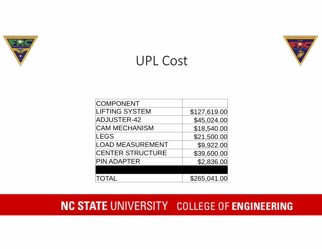
UPL Cost
COMPONENTLIFTING SYSTEM $127,619.00ADJUSTER-42 $45,024.00CAM MECHANISM $18,540.00LEGS $21,500.00LOAD MEASUREMENT $9,922.00CENTER STRUCTURE $39,600.00PIN ADAPTER $2,836.00
TOTAL $265,041.00

Added CapabilitiesOur Universal Proofloader Will:• Proofload all known slings in their usage configuration.
• No more contracting out proofloading of slings.
• No more time lost shipping slings to other FRC locations.